control of on-orbit contamination for the argos · pdf file · 2013-08-30control of...
TRANSCRIPT

N 9 3 - 1 5 G ] 7
CONTROL of ON-ORBIT CONTAMINATION for the ARGOS (P91-1) SATELLITE
Joseph G. Kelley
Rockwell International
ABSTRACT
The ARGOS (P91-1) satellite presents a challenging combination of on-
orbit contamination concerns while mandating a low-cost approach. Several
experiment payloads contain contamination sensitive optics, another con-
tains large quantities of CO 2 and Xe for release in orbit, and one contains
an NH 3 fueled arc jet thruster. The latter includes a suite of sensors to
measure contamination; so prelaunch calculations will be tested. Planned
contamination control techniques include: physical separation of sensitive
surfaces from contamination sources; flight covers to protect sensitive
surfaces during early outgassing on-orbit; gas release and thruster opera-
tion early in the flight, before flight covers are opened; and careful con-
trol of plumes and venting through a detailed analysis of each.
INTRODUCTION
The Air Force, Space Test Program, satellite ARGOS (Advanced Research
and Global Observation Satellite), otherwise known as P91-1, will carry a
number of experiments in an 833 km (450 nmi) polar orbit (98 ° inclination)
in 1995. One year of experiment operation is planned, but the vehicle is
designed for a three year on-orbit life. The diversity of the experiments
presents a number of contamination control concerns; while the nature of
the program mandates a low cost approach. This paper presents the contami-
nation requirements and concerns, describes the contamination control ap-
proach, and provides an estimate of launch and post launch accumulations.
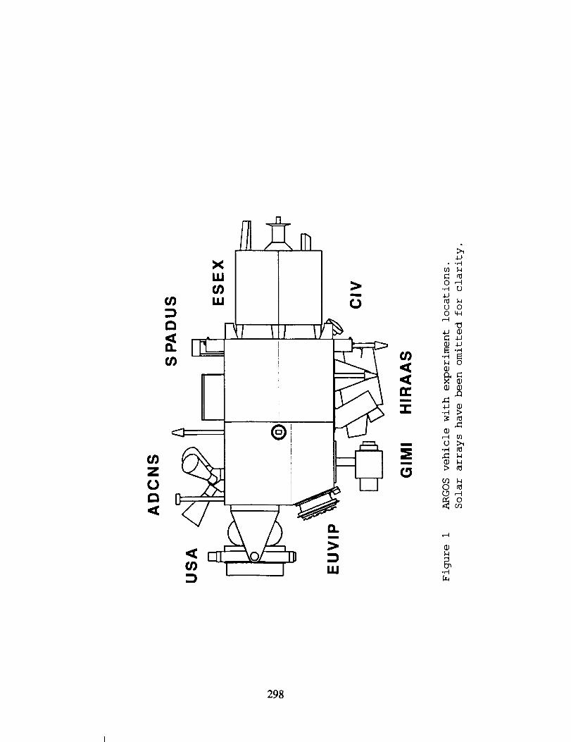
The current vehicle concept is shown in figure i. A brief summary of
the experiments is provided in table I.
CONTAMINATION CONCERNS and ACTIONS
Contamination Impact
Contamination is of concern primarily for its impact on experiment and
vehicle End of Life (EOL) capabilities. For optical instruments, including
optical attitude sensors, contamination attenuates the signal by absorbing
and scattering the incoming signal, and may increase noise by scattering
unwanted radiation into the sensor. Contamination on thermal control sur-
faces causes an increase in solar absorptivity proportional to the area ob-
289
https://ntrs.nasa.gov/search.jsp?R=19930006428 2018-05-19T19:23:12+00:00Z

scured by particles and the molecular film thickness. The change in emis-
sivity can usually be neglected (ref i). The radiators will not be suffi-
ciently colder than the rest of the space vehicle that condensation of con-
taminants is a concern. Molecules will attach to a surface only if poly-
merized, by solar UV, to form a compound with a much lower vapor pressure
(ref 2). Thus, shadowed thermal surfaces are of less concern than sunlit
ones. Molecular contamination on solar arrays decreases power (ref 3) as
shown in figure 2. The power loss for the expected particle obscuration
(~1%) will be negligible (ref 4).
The major contamination sensitivities and EOL requirements, for both
the experiments and the space vehicle (SV), are summarized in table II to-
gether with the intended precautions. As described below, the ESEX and CIV
experiments have much shorter mission lives than the other experiments.
Precautions
On-orbit contamination control, for ARGOS, is achieved by four meth-
ods: materials selection, geometry control, flight covers, and time phasingof operations.
All outgassing materials must meet the usual criteria: Total mass
loss less than 1% when heated to 125 °C for 24 hours, and collected
volatile material on a 25 °C witness plate less than 0.1%. It has been as-
sumed that: I. the outgassing so measured represents the total loss over
mission life; 2. the collected material consists of heavy (~150 amu), poly-
merizable molecules; 3. the uncollected material is light (~18 amu), non-
polymerizable molecules. These assumptions are crude, but are the best
values available until the actual materials are defined and measured.
The geometry is shown in figure 3. Emissions, both internal outgas
products and thruster plumes, are restricted, in so far as possible, to one
end of the vehicle. USA was mounted on the rear to minimize meteor and de-
bris impacts; this required that CIV and ESEX be mounted on the front. The
mean free path in the ambient atmosphere is 1600 km; so there are no ram
effects. The attitude control thrusters, which share the CIV gas supply,
are not shown. In an emergency they will be used to orient the vehicle in
a sun-safe mode pending ground intervention. If used, they will emit small
CO 2 plumes to the sides; the contamination effects will be negligible. USA
has a small leakage of argon with a trace of methane, and the emitting facecan be rotated 90 ° up and down. However, these gasses are noncontaminat-
ing, the amount is small, and they do not impinge on the vehicle: they are
not a contamination problem.
The optical surfaces of the experiments require a much greater clean-
liness than can be economically achieved for rest of the space vehicle.
These will be provided with flight covers and controlled internal environ-
29O
ments by the experimenters. The covers will remain closed from delivery
for integration until favorable conditions are achieved on-orbit, as dis-
cussed below. If they must be opened before launch, e.g. for testing, it
will be under the direction of the experimenter, who will be responsible
for maintaining experiment cleanliness. After opening, the optical ele-
ments will not be permitted to view outgassing surfaces, e.g. solar arrays;
exceptions will be at the experimenter's risk.
Finally the on-orbit operations have been time phased to limit cross
contamination. During phase 1 (two days to two weeks) all experiments will
be off, flight covers will remain closed, and no high voltage surfaces will
be exposed while the vehicle is checked out and tested. Phase 2 (4-6
weeks) will be devoted to ESEX and CIV operations. The other experiments
will remain off, with flight covers closed, and no high voltages will be
exposed, except for ESEX operation. Phase 3 will start with a brief (one
week) delay to allow any residual thruster effects to disperse. At this
point (~ week 8 on orbit) over half of the total outgassing will have oc-
curred and the outgassing rate will be about a tenth of its value at the
end of the first day on orbit. Flight covers will now be opened and the
operation of the rest of the experiments initiated.
CONTAMINATION SOURCES AND ACCUMULATION
Prelaunch
All exposed surfaces (thermal control surfaces, experiment exteriors,
etc) will be cleaned immediately before packing for shipment to the launch
site. This cleaning will be to Visibly Clean Level I, which corresponds to
an obscuration of 0.5% by particles and less than one microgram/cm 2
(100 Angstrom (A)) molecular film. Thereafter the space vehicle will be
protected in a I00,000, or better, cleanroom until launch (122 days); most
of this time will be in a class I0,000, or better, environment. This expo-
sure will add 2% obscuration to upward facing surfaces and 0.1% particle
obscuration to other surfaces. It will also add i00 A of molecular film to
all exposed surfaces. The satellite will be maintained in a vertical posi-
tion with USA uppermost. There will be some redistribution of large parti-
cles by transportation and handling shocks, but these are not expected to
significantly increase the particle density on any critical surface.
Ground covers (solar arrays, attitude sensors, ESEX diagnostics) will
be removed at payload fairing closure. These surfaces will be visibly
clean level I, except for the ESEX diagnostics which will be level II (for
definition see below). The prelaunch exposure time for these surfaces will
be only five days, which will increase the obscuration of non-upward facing
surfaces by 0.004% (no sensitive surface faces upward in this orientation
of the satellite). These surfaces will acquire a total of 12 A additional
molecular film while covered and during the five days exposure.
291

Launch/Venting
The payload fairing will be cleaned to Visibly Clean Level II, which
corresponds to 0.1% particle obscuration and less than one microgram/cm 2
molecular film. During launch most particles larger than 5 microns will be
shaken free and, unless swept out by the vented gas, will redeposit, pri-
marily on the upward facing surfaces. Assuming a two to one area ratio due
to the curvature of the fairing, one finds an obscuration increase of less
than 0.3% on upward facing surfaces and 0.02% on other surfaces. Molecular
film addition will be less than 20 Angstroms due to fairing emissions and
and thruster splash. Since there are no cold surfaces to condense
molecules and no sunlight to polymerize them, it is assumed that the vented
gasses have no contamination effect.
Plumes
ESEX emits 0.25 gm/sec of ammonia (NH3) , nitrogen (N2, N), and hydro-
gen (H2,H) . It may also emit trace amounts of contaminants and trace
amounts of metallic dust (from the electrodes). There will be ten firings
of fifteen minutes each. The experimenter has provided a Monte Carlo anal-
ysis showing that most of the emission is confined to a cone centered on
the arc axis. Self interaction produces a small amount of backscatter,
mostly hydrogen with small amounts of ammonia and nitrogen. This conforms
to the expectation that conservation of momentum will cause preferential
backscattering of the lightest components. These emissions are not expect-
ed to present a contamination problem to the rest of the vehicle.
CIV will release twenty bursts each of carbon dioxide (CO2) and Xenon
(Xe); ten seconds per burst, i00 gm/sec. The gasses will expand, and cool,
supersonically (See table III for parameters). It is expected that 75% of
the gas will remain within 45 ° of the vent axis and 95% within 75 ° (ref 5).
The CIV emissions will be very clean, contaminants of concern will be less
than one part per million. However, outgas products may be entrained and
scattered by the heavy Xe atoms. Also, the CIV plume can produce pressures
up to 0.03 Torr or more at points a meter forward of the nozzle. High
voltages must not be exposed to these pressures. Pressures at points be-
hind CIV and within enclosures must be calculated on a case by case basis.
Outgassing
The material list is not yet available; so one must make some assump-
tions to calculate the outgassing. The Tribble and Haffner (ref 3) assump-
tion that the mass of outgassing material interior to the vehicle is equal
to one-third the mass of the boxes and wiring, was valid for GPS and ap-
pears reasonable for use here for internal emissions. One must also con-
sider external emissions from the Thermal Control Surfaces (TCS) and the
solar arrays (adhesives and substrate). Estimates are provided in table
292
IV. It is expected that outgassing will be completed in less than three
years at the temperatures expected.
The outgas effluents of concern, those capable of being polymerized by
solar UV, are very heavy molecules, > 150 amu, and their mean free path is
long, on the order of meters or more. They will be emitted, with a
Lambertian cosine distribution, in straight lines; a threat only to sur-
faces in line of sight (LOS) of the vent: the shaded side of ESEX and pan-
els two and three of the solar array on that side.
There is one exception to the line of sight rule: the Xenon atoms from
CIV may entrain the heavy contaminants and carry them to the ESEX diagnos-
tics. The CO 2 molecules are not heavy enough (44 amu) to significantly di-
vert the heavy contaminants (>150 amu), but Xenon (131 amu) may have some
effect. CIV operation may begin as early as the second day (t:8.6x10 4 sec)
on orbit. Space vehicle temperature will be about 300 K. The outgas rate
formula used by Tribble and Haffner,
dm/dt = 3100 x M 0 x exp(-5032/T) / tl/2), (i)
gives a total deposit of about 20 nanograms/cm 2 on the ESEX diagnostics,
after 200 seconds exposure (120 exposures, i0 seconds each) if 2% of the
incident flux is polymerized.
Each solar array consists of three panels, each 144 cm long. The pan-
els are angled 60 ° to their rotation axis at a point 17 cm from the vehi-
cle. The first panel is mounted 74 cm from the pivot (figure 4). Panels
two and three of the solar array on the vent side are exposed to the efflu-
ent when they extend beyond the plane of the vent. For simplicity, the
distance and angle to the midpoint of each panel, at its point of closest
approach to the vent, was used for the entire area of the panel. Exposure
is modified by the cosine effect of the Lambertian emission, the cosine of
the angle between the incident flux and the panel normal, and the fraction-
al exposure time. Tribble and Haffner's maximum polymerization factor of
0.008 was used. The calculated deposit is less than I00 nanograms per
square centimeter on each panel; this has negligible effect on the power
generation when averaged over all six panels.
All solar panels see emissions from the vehicle surface materials.
Allowing a cos 60 ° modification of panel area and allowing 0.8% polymeriza-
tion as before, the total deposit is less than I000 nanograms/cm 2 for panel
i, 390 nanograms/cm 2 for panel 2,and 210 nanograms/cm 2 for panel 3.
Combining this with the deposit from the vented material gives no more than
a microgram/cm 2 for any panel and little impact on the total power output.
The vehicle thermal control surfaces, and the radiator on the sunlit
side of ESEX will be exposed to outgas products from the solar arrays.
293
Totaling the emissions from the three panels (with proper distances for
each), including a 60 ° factor for Lambertian emission, and using a _olymer-ization factor of 2%, one finds deposits up to 1.6 micrograms/cm=. This
corresponds to an absorptivity increase of 0.008. Note that minimum dis-
tances were used and the receiving surfaces were assumed to be perpendicu-
lar to the line of sight; both cause overestimation of the effect.
SUMMARY
The objective is to provide low cost contamination control for a
satellite with diverse experiments. This is done by controlling materials,
controlling the locations and fields of view of the experiments, using
flight covers over the optical surfaces, and time phasing the on-orbit op-
erations. The results are summarized in table V. All requirements are
satisfied with adequate margins. Given the added consideration of the con-
servative nature of the approximations, the margins become very comfort-able.
294

REFERENCES
I. Hamberg, O.; Tomlinson, F.D.; Sensitivity of Thermal Surface Solar
Absorptance to Particulate Contamination; AIAA 6 th Thermophysics
Conference; p 137-151; April 1971
2. Stewart,T.B.; Arnold, G.S.;Hall,D.F.;Marten, H.D.; Absolute Rates of
Vacuum-Ultraviolet Photochemical Deposition of Organic Films; J Phys Chem,
93; pp 2393-2400, 1989
3. Tribble,A.C.; Haffner, J.W.; Estimates of Photochemically Deposited
Contamination on the GPS Satellites; J Space & Rockets; 28; pp 222-228;
1991
4. Raab, J.H.;Particulate Contamination Effects on Solar Cell Performance;
Final Report,MCR-86-2015, Rev A, Contract F04701-83C-0045, Jan 1987
5. Scialdone, J.J.; Flow Fields of Low Pressure Vent Exhausts; 16th Space
Simulation Conference, pp 75-83, Nov 1990
295

Table I ARGOS EXPERIMENTS
EXPERIMENT SOURCE INSTRUMENT/TECHNIQUE
ClV
ESEX
USAF/Phillips Lab
USAF/Phillips Lab
Critical Ionization Velocity;
C02 and Xe Release
Arcjet Propulsion;
NH3 Propellant
EUVIP Army EUV Imager
NRL
NRL
GIMI
HIRAAS
Far UV Cameras
Extreme and Far UV
Spectroradiometer
Stellar X-Ray ObservationUSA NRL
ADCNS DARPA Attitude & Navigation;
Celestial Star Tracking
SPADUS ONR Space Dust Measurement
Table II CONTAMINATION CONCERNS AND PRECAUTIONS
ELEMENT CONCERN PRECAUTION EOL REQUIREMENT
CIV Orifice Blockage, Use Hydrazine Spec *<20 ppm Emitted
Gas Cleanliness for Components Contamination
ESEX
-Diagnostics Sensor Background Ground Cover, * 4 m <5/_ gm/cm2
-Radiator Absorptivity Clean Before Launch *_ < 0.08
EUVlP
GIMI
HIRAAS
ADCNS
USA
SPADUS
Shaded TCS
Sunlit TCS
Solar
Arrays
Attitude
Sensors
Throughput Loss
None
Absorptivity** Loss of
Illumination
Loss of Throughput
Flight Covers,
No LOS to SV
Not Applicable
Limit Venting,
Clean before Launch
Ground Cover
ExperimenterDetermined &
Controlled
Not Applicable
d _ <0.08
P/P < 0.02
Throughput
Loss < 20%
* EOL = End of Phase 2; ** Contamination Driver
296
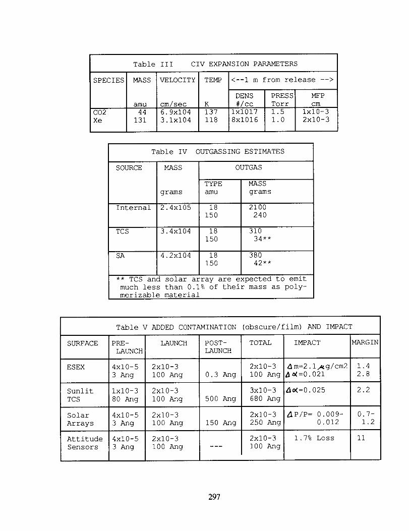
Table III CIV EXPANSION PARAMETERS
SPECIES MASS VELOCITY TEMP <--I m from release -->
DENS PRESS
#/cc Torr
Ix1017 1.5
8xi016 1.0
MFP
cmamu cm/sec K
CO2 44 6.9xi04 137 Ix10-3
Xe 131 3.1xi04 118 2xi0-3
Table IV OUTGASSING ESTIMATES
SOURCE MASS OUTGAS
TYPE
amu
MASS
gramsgrams
Internal 2.4xi05 18 2100
150 240
TCS 3.4xi04 18 310
150 34**
SA 4.2xi04 18 380
150 42**
** TCS and solar array are expected to emit
much less than 0.1% of their mass as poly-
merizable material
Table V ADDED CONTAMINATION (obscure/film) AND IMPACT
SURFACE PRE- LAUNCH POST- TOTAL IMPACT MARGIN
LAUNCH LAUNCH
ESEX 4xi0-5 2xi0-3 2xi0-3 dm:2.1_g/cm2 1.4
3 Ang i00 Ang 0.3 Ang i00 Ang _=0.021 2.8
_=0.025 2.2Sunlit
TCS
Solar
Arrays
Attitude
Sensors
ix10-3
80 Ang
4xi0-5
3 Ang
4xi0-5
3 Ang
2xi0-3
i00 Ang
2xi0-3
i00 Ang
2xi0-3
i00 Ang
50O Ang
150 Ang
3xi0-3
680 Ang
2xi0-3
250 Ang
I 2x10⁻³i00 Ang
P/P= 0.009-
0.012
1.7% Loss II
297
XI.U
wmmmm
0
,<
l w
mm
• *r-_
0-,-iL)
o oo o_
4a •4a
-,.-I-,--t N
0
N (1)
-,--t _
0,---t m
-,-'1 _
_°u'l
r--t
0
g-,.-t
298

oQ_
DQ.
DO
_JWo
O00
UJ
W
1.00
.9
.80
.75
\
0.01I I I I IIII I I
0.1I Innnl
CONTAMINATION THICKNESS
1 micron
Figure 2 Solar Array Power is a function of molecular film thickness (It
was assumed that 0.01 microns is equivalent to one microgram per
square centimeter).
299

I
E
.IJ
00
0
Q;
-,-I
o00O.
n_
-,--I
0
_ 0
_ 0
I1) 0
-,-.t
-,-t 0ffl -,--I
c_
-,--I
300

Figure 4 Each solar array is angled 60 ° to the rotation axis for the
array.
301
