control systems
DESCRIPTION
control systemsTRANSCRIPT

Control systemsFEEDBACK AND FEEDFORWARD CONTROL SYSTEMS
Control system definition
A control system is a device, or set of devices to manage, command, direct or regulate the behaviour of other device(s) or system(s)
There are two common classes of control systems, with many variations and combinations: logic or sequential controls, and feedback or linear controls. There is also fuzzy logic, which attempts to combine some of the design simplicity of logic with the utility of linear control.

Block diagrams

Feed back control
Advantages Corrective action taken regardless of disturbance source
Minimal process information required for controller design
PID control is very versatile and usually effective
Disadvantages Corrective action not taken until after the output has deviated from
the setpoint
Requires measurement of the controlled output
Does not allows measured disturbances to be utilized
Problematic for processes with large time constants and/or long time delays

Feedforward control
Major disturbance is measured and used as the controller input
Advantage Corrective action can be taken before the output has deviated from the
setpoint
Particularly useful for processes with large time constants and/or long time delays
Disadvantages Disturbance must be measured
Provides no advantages for other disturbances
Typically requires a process model

Stirred Tank example

7
Figure 15.2 The feedback control of the liquid level in a boiler drum.

8
Figure 15.3 The feedforward control of the liquid level in a boiler drum.

Description
• A boiler drum with a conventional feedback control system is shown in Fig. 15.2. The level of the boiling liquid is measured and used to adjust the feedwater flow rate.
• This control system tends to be quite sensitive to rapid changes in the disturbance variable, steam flow rate, as a result of the small liquid capacity of the boiler drum.
• Rapid disturbance changes can occur as a result of steam demands made by downstream processing units.
10
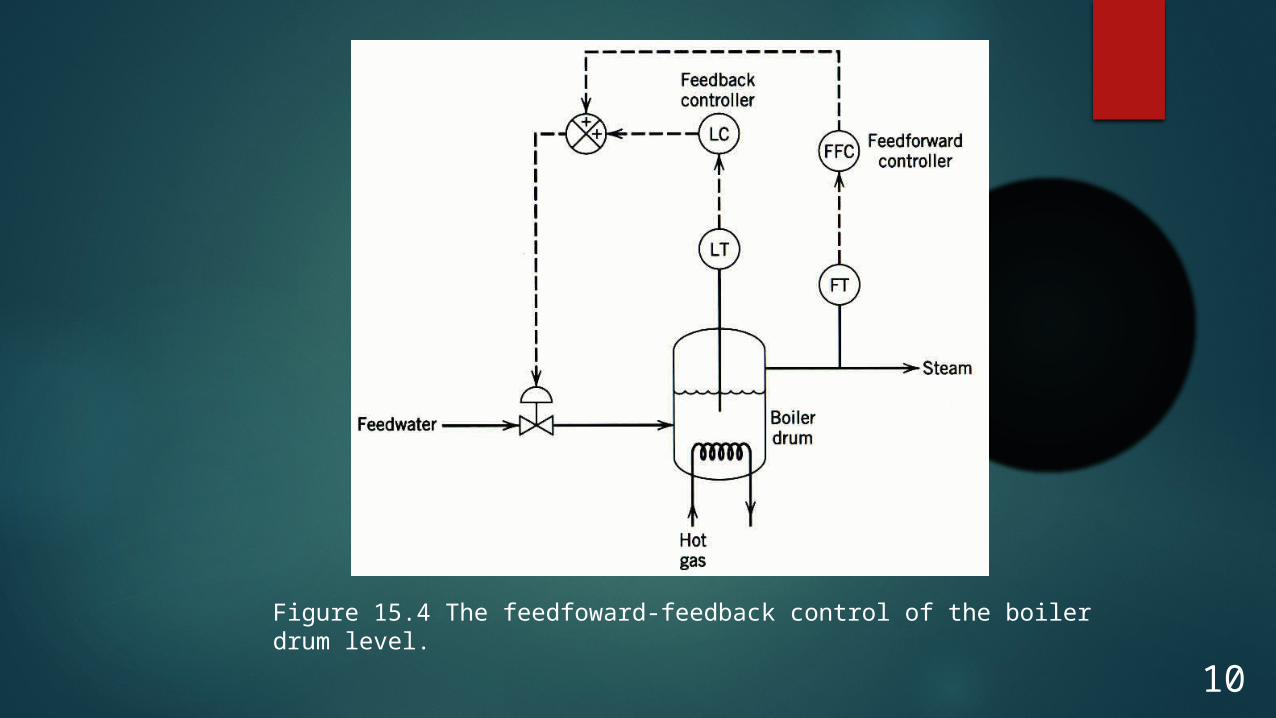
Figure 15.4 The feedfoward-feedback control of the boiler drum level.

DESCRIPTION
• In practical applications, feedforward control is normally used in combination with feedback control.
• Feedforward control is used to reduce the effects of measurable disturbances, while feedback trim compensates for inaccuracies in the process model, measurement error, and unmeasured disturbances.

Ratio Control
Ratio control is a special type of feedforward control that has had widespread application in the process industries. The objective is to maintain the ratio of two process variables as a specified value. The two variables are usually flow rates, a manipulated variable u, and a disturbance variable d.
(15-1)u
Rd

13
Typical applications of ratio control include:
1.Setting the relative amounts of components in blending operations
2.Maintaining a stoichiometric ratio of reactants to a reactor
3.Keeping a specified reflux ratio for a distillation column
4.Holding the fuel-air ratio to a furnace at the optimum value.

14
Figure 15.5 Ratio control, Method I.
15
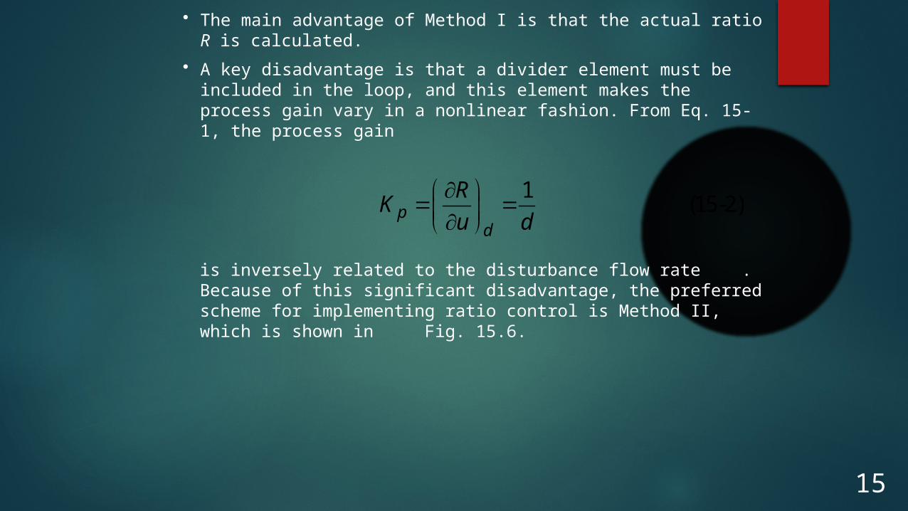
• The main advantage of Method I is that the actual ratio R is calculated.
• A key disadvantage is that a divider element must be included in the loop, and this element makes the process gain vary in a nonlinear fashion. From Eq. 15-1, the process gain
1(15-2)p
d
RK
u d
is inversely related to the disturbance flow rate . Because of this significant disadvantage, the preferred scheme for implementing ratio control is Method II, which is shown in Fig. 15.6.

16Figure 15.6 Ratio control, Method II

17
• Regardless of how ratio control is implemented, the process variables must be scaled appropriately.
• For example, in Method II the gain setting for the ratio station Kd must take into account the spans of the two flow transmitters.
• Thus, the correct gain for the ratio station is
(15-3)dR d
u
SK R
S
where Rd is the desired ratio, Su and Sd are the spans of the flow transmitters for the manipulated and disturbance streams, respectively.

Disturbance Rejection
0 2 4 6 8 10 12 14 16 18 20-2
-1.8
-1.6
-1.4
-1.2
-1
-0.8
-0.6
-0.4
-0.2
0
0.2
Time
Inpu
t
Feedback
Feedback-Feedforward
0 2 4 6 8 10 12 14 16 18 20-0.1
0
0.1
0.2
0.3
0.4
0.5
0.6
Time
Out
put
Feedback
Feedback-Feedforward
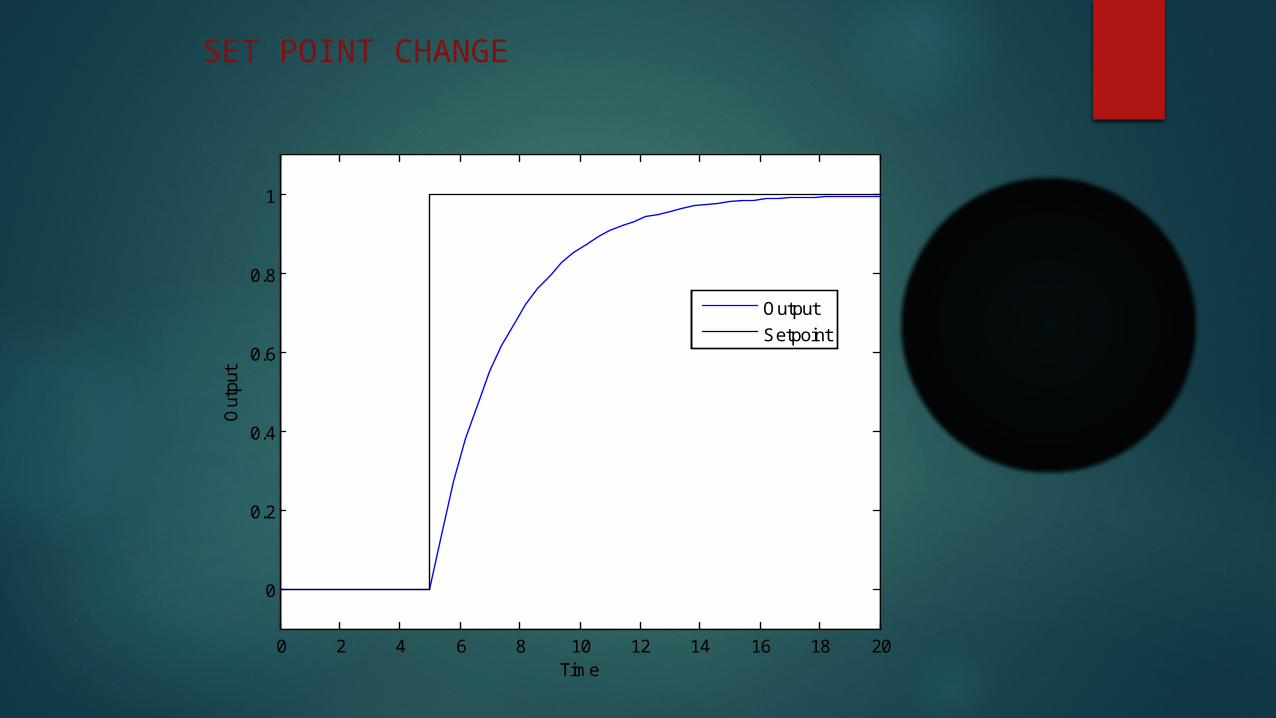
SET POINT CHANGE
0 2 4 6 8 10 12 14 16 18 20
0
0.2
0.4
0.6
0.8
1
Out
put
Time
Output
Setpoint

TEJA TSSV
THANK YOU