control systems - velocity · pdf file10 - control systems page 8 10-ugf june 2004 10.1 yoke...
TRANSCRIPT

10 - Control Systems
June 2004 10-UGF Page 1
Control Systems

10 - Control Systems
Page 2 10-UGF June 2004
○
○
○
○
○
○
○
○
○
○
○
○
○
This pageIntentionallyLeft Blank

10 - Control Systems
June 2004 10-UGF Page 3
. Contents10.0.1 Parts List- ................................................................................................ 10-410.0.2 - Tools List- ............................................................................................. 10-610.0.3 - Supplies List- ......................................................................................... 10-610.0.4 - Glass List- ............................................................................................. 10-610.0.5 - Process Overview- ................................................................................ 10-6
10.1 Yoke Installation- ..............................................................................10-810.1.1 Drilling The Panel for Yoke Installation- ..................................................... 10-810.1.2 Aileron Control Assembly- ....................................................................... 10-810.1.3 Mounting The Aileron Control Assembly- .................................................. 10-810.1.4 Attaching the Elevator to the Yoke - .......................................................... 10-910.1.5 Installing the Aileron Controls- ................................................................ 10-10
10.2 Rigging of the Roll System (Ailerons)- .........................................10-1310.2.2 Aerodynamic Trim (Sparrow Strainer)- ................................................... 10-1910.2.3 - Elevator Trim- ...................................................................................... 10-2010.2.4 - Rudder Cable Installation- .................................................................... 10-21

10 - Control Systems
Page 4 10-UGF June 2004
○
○
○
○
○
○
○
○
○
○
○
○
○
10.0.1 Parts List
Part Number Description QtyElelvator Pushrod 2
AN3-16A Bolt 2AN960-10 Washer 25MS21042-3 Locknut 19
Roller Bearings 4AN3-23A Bolt 2MS27039-1-04 Screw 4AN970-3 Washer 6
C-Clip Retainer 2PBW PB Washer 4PBB-01 PB Braket 4
Phenolic Pivot Block 210/32 3/8" 10/32 Machine Screws 4
Copilot Aileron Pushrod Assembly 1Pilot Aileron Pushrod Assembly 1
EAB-01 Elevator Attach Block 2EAB-02 Elevator Attach Block Spacer 2EAB-03 Elevator Attach Block Washer 4AN3-10A Bolt 6AN960-10L Washers 8AN3-15A Bolt 2AN5-13A Bolt 1AN960-516 Washers 5MS21045-5 Locknut 1KBA Keel Bellcrank 1KBS Keel Support 1AN3-5A Bolt 4AN970-3 Washer 4MW-4 Rodend 4

10 - Control Systems
June 2004 10-UGF Page 5
P art N um ber D escrip tio n Qty1/4 -28 Jam nut 4
K C A A ng le 1A N3-6A bo lt 4
C lam p 4S him 4
A N4-13A B olt 1A N970-4 W asher 2A N960-416 W asher 4M S 21042-4 Locknut 1M S 24694S -59 S crew 2K B S A ng le 1#10 S heetm eta l screws 2A N3-5A B olt 1V A UJ-01 5/8x.058 stee l tube 3" 2V A TT-01 3/4" a lum inum tub ing 2
A ileron B e llC rank 2M S 24693S -272 F la thead S crew 8A N4-10A B olt 2A N960-416 W asher 4M S 21042-4 Locknut 2M S 27039-1-07 S crew 8
S parrow S tra iner 1E levato r Trim S pring 1S pring B racke t 1S ta inless S tee l C ab leNicopress 8Thim ble 6S leeve 4Rudder C able P ulley 2Rudder A ng le B racke ts 4
#8 S heetm eta l screws 8

10 - Control Systems
Page 6 10-UGF June 2004
○
○
○
○
○
○
○
○
○
○
○
○
○
10.0.2 - Tools ListDescription
1" Hole Saw#22 Drill3/16 Drill1/2" Drill10-32 Tap4 Clamps
10.0.3 - Supplies ListDescription
Milled FiberStructural AdhesiveEZ-PoxyDuct Tape(Blue) Removable Loctite
10.0.4 - Glass ListType Size Qty
Bid 1/2" x 3" Aprox. 6
10.0.5 - Process OverviewCompletion
DateYoke Installation
Drill PanelAssembly of YokeMounting the Aileron Control AsemblyAttaching the ElevatorInstalling the Aileron Controls
Rigging Control SurfacesRigging the AileronInstallation of the Sparrow StrainerElevator Trim attachmentRudder Cable installation
Construction Process

10 - Control Systems
June 2004 10-UGF Page 7
This PageIntentionallyLeft Blank
10 - Control Systems
Page 8 10-UGF June 2004
○
○
○
○
○
○
○
○
○
○
○
○
○
10.1 Yoke InstallationTo install and rig the rest of the control systems in a Velocity equipped with yokesyour aircraft must be assembled to the point that the wings, winglets, etc. are at-tached. First we will install the Yoke System.
In the previous chapters you installed the elevators to the canard, installed the torquearms to the elevators and installed the canard to the airframe.
10.1.1 Drilling The Panel for Yoke Installation
First you will mount the yoke to the aileron control assembly. Place the aileron con-trol assembly in a vice and insert the yoke onto the end of it. Orientate the yoke so it ispointing up opposite the bellcrank on the end of the aileron control assembly. Keepthe horizontal center section of the yoke perpendicular the bellcrank. You will nowneed to drill a hole through both the yoke and the stainless steel tubing to mount theyoke. This hole can be drilled vertically or horizontally. Vertically is easier butleaves more of the bolt exposed. If you decide to drill the hole horizontally you mayneed to use a special facing tool to make the surface under the head of the bolt and nutflat. Drilling an undersized hole and using a reamer to ream the hole to 3/16” willensure a tight fit. Make sure the the center of the hole is at least 9/32” from the edge ofthe aluminum. You will assemble the yoke to the shaft using an AN3-15A bolt with(2) AN9960-10 washers and an MS21042-3 nut.
The instrument panel must be installed in the airplane for this step. It is recom-mended the panel be installed as a “removable” item. Double check these dimen-sions to make sure your panel is in the correct locations. Below are directions forboth the standard and XL Velocities.
STD From the nose back to the panel sides diagonally is 62-1/2”. From the floor of theairplane just outside the keel to the bottom of the panel is 16-1/2”.
XL The instrument panel should be 21” back from Canard bulkhead. The bottom of panelis 16-3/4” off the floor measured just outside the keel in the middle of the plane.
STD On a standard flat panel you have 2 sets of dimpled holes on the face of the panel.Draw a line connecting them using a straight edge. Measure the distance betweeneach set of dimples and place a center mark. With a 1 inch hole saw, drill two holescentered on your marks. These holes are where the elevator push rod portion of theaileron control assembly will come through the instrument panel.
XL On an XL measure 5-1/4” up from the base of the panel and place a mark. After thepanel has been fit to the airplane draw a center mark on the panel using the center ofthe keel as a reference. From this mark measure 11-5/8” out and place a mark over-lapping your previous mark. With a 1 inch hole saw drill two holes in your panelcentered on these marks.
Important: When you are laying out your panel for instrumentation, rememberyou now have two yoke systems that are taking up panel space. Don’t think twodimensionally when laying out your panel. Every instrument has depth.
10.1.2 Aileron Control Assembly
___ The Aileron Control Assembly will be provided as a fitted and pre-assembled part. Verifythat the elevator push rod portion of the assembly moves freely through its travel and thatnothing in the pre-assembly is showing a bind and/or looseness. Even though the mecha-nism is pre-assembled, the ultimate integrity of the assembly is up to you the builder.Verify that all components are in their proper position, that bearings are free to turn andthat in general the assembly looks secure. Refer to Figures 10-1 and 10-2 for clarifica-tion.

10 - Control Systems
June 2004 10-UGF Page 9
10.1.3 Mounting The Aileron Control Assembly
Note: Canard must be installed with elevator and torque tubes for this step.
Place the aileron control assembly behind the instrument panel with the elevator pushrod coming through the 1 inch hole you drilled earlier. Refer to figure 10-1.
(2) PB Washers
10-32 3/8“
PBB-01 Bracket
(2) AN3-5A
(2) AN960-10
Snap RingFigure 10-1. Phenolic Pivot Block
With the canard in place, rest the forward end of the elevator push rod on top of it.Turn the PBB-01 bracket attached to the phenolic block so that it is flat against theinstrument panel. Make sure that your elevator push rod is centered in the hole andthat the PBB-01 bracket is horizontal . Holding the brackets tight against the instru-ment panel, mark around the PBB-01 bracket. Remove the PBB-01 bracket from theassembly and hold it back up to your marks. Now using a #21 drill bit, drill a holethrough one of the two premarked screw holes in the PBB-01 bracket and throughthe instrument panel. Using a 3/16” drill bit open up the hole in the instrument paneland countersink the face for a countersunk screw. Tap the hole in the PBB-01 bracketwith a 10-32 tap. Install a countersunk 10-32 screw through the instrument panel intothe PBB-01 bracket. With the first screw tight, center up the other side and drill it.Repeat this step for your other yoke.( Note: The brackets used to hold the controlassembly to the instrument panel are quite large and depending on your panel layoutmay interfere with instrument mounting.)
10.1.4 Attaching the Elevator to the Yoke
For this step the canard must be in place with the elevators attached. The elevator attachblock, washers and spacer have been pre-assembled onto the aileron control assembly.Check for integrity. Install the elevator attach L-brackets using an AN3-28 bolt, (2)AN960-10L washers, (2) AN960-10 washers and an AN310-3 nut. (Refer to figure 10-2)
AN3-28Cotter PinAN 310-3 Castle nut
AN960-10L (2)
AN960-10 (2)
AN960-10 (4)
MS27039-1-04 Aileron Control Bellcrank
AN3-16A
Roller Bearings
Figure 10-2. Top View Aileron Control Assembly.
10 - Control Systems
Page 10 10-UGF June 2004
○
○
○
○
○
○
○
○
○
○
○
○
○
Make sure the control assembly is perpendicular to the instrument panel and confirmthat the center-to-center distance between the two L-bracket assemblies is 19-1/2”.(23-1/4” on an XL) Position the elevators so that the trailing edge is 26 degreesdown. The roller bearings should be at the back (aft end) of the groove in the aileroncontrol assembly. Attach the L-brackets to the concentric elevator torque tube usingC-clamps. Each L- bracket assembly is actually 2 parts. The second part clamps onthe opposite side of the concentric elevator torque tube.
Verify alignment in all directions. Drill through both the base of the L-bracket throughthe concentric torque tube and the opposite side of the L-bracket assembly using a 3/16” drill bit. You may wish to use an undersize frill bit and ream the holes to 3/16” asyou did in your elevator installation. Install with one AN3-15A bolt, one AN960-10washer and a MS21042-3 nut for each bracket assembly.
10.1.5 Installing the Aileron Controls
The first part of the aileron control system to be configured is the Aileron KeelBellcrank assembly. The assembly consists of a bellcrank, channel and bracket, pushrods and attachment hardware. Refer to Figure and 12-4 for clarification. This willneed to be trimmed to 15-1/2” in a standard fuselage in order to fit.
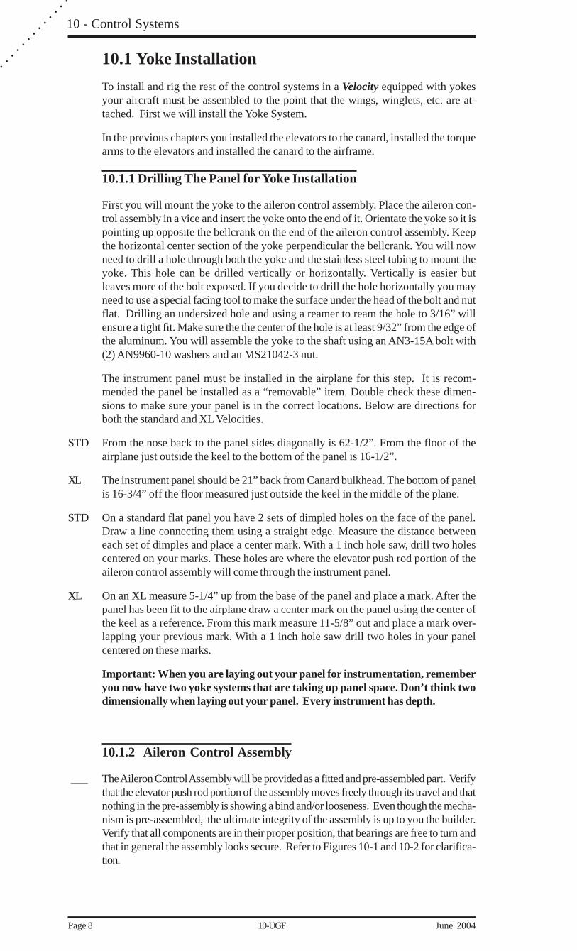
Install the aileron Bellcrank into the keel support channel using (1) AN5-13A bolt,(5) AN960-516 washers and (1) MS21045-5 nut. Arrange the washers according toFigure 12-3
Test fit the Horizontal Brace (with bellcrank installed and lower bracket attached)into the position shown in Figure 10-4. Make sure the keel bellcrank is in line withthe two aileron control arms. Use a C-clamp to temporarily hold the horizontal braceto the keel as you install the system. With all three bellcranks/arms vertical, measurethe lengths between attach points and adjust rod end lengths to match. (Note: Bothleft and right hand threaded rod ends are provided which allow adjustment of the rodlengths when they are installed .) Assemble the push rods to the aileron bellcrank andthe two aileron control arms that are a part of each aileron control assembly. Refer to10-4.
(1) MS21045-5
(5) AN960-516(2 on right side and1 on left side)
AN 5-13A
Figure 10-3. Top View of Keel Bellcrank.

10 - Control Systems
June 2004 10-UGF Page 11
(1) AN3-5A(1) AN960-10(1) MS41042-3(2)#10 Sheetmetal screws
Figure 10-4. Front View looking aft of Aileron Controls.
Confirm that the aileron push rods are pointed up towards the keel bellcrank whenthe system is centered. Fine tune length of push rod by rotating center shaft. Refer tofigure 10-4 and the picture below. We now need to turn our aileron control assemblyfull left and right and make sure that the assembly does not go over center in eitherdirection. If it does the Keel Bellcrank is too low. If installed correctly the push rodsshould almost be level at each end of there travel. There is a breakable tab that istemporarily welded to the bottom Keel bellcrank assembly. This tab should be touch-ing the floor when your assembly is in the correct position. Refer to figure 10-4.When satisfied with arrangement drill a 3/16” hole 2” down from the bellcrank throughthe support and side of keel and one 2” from the bottom of the support. Install (1)AN3-5A bolt, (1) AN960-10 washer, (1) AN970-3 washer on the inside of the keeland (1) MS21042-3 nut per hole. After installation break off tab at bottom of assem-bly.
10 - Control Systems
Page 12 10-UGF June 2004
○
○
○
○
○
○
○
○
○
○
○
○
○
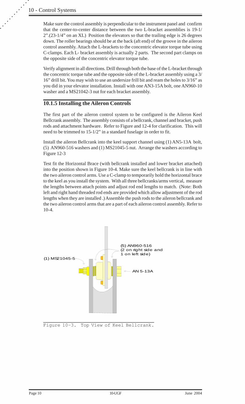
Firewall(From inside fuselagelooking Aft)
Center Spar
Copilot Side1/2“ hole
Pilot Side1/2“ hole
2“ up from lowerspar cap no more than 1“ from the side
StandardJust under the spar capno more than 1“from the side.
XL
2“ up from lowerspar cap no more than 1“ from the side
Figure10-5 Aileron Cable routing through Firewall
10 - Control Systems
June 2004 10-UGF Page 13
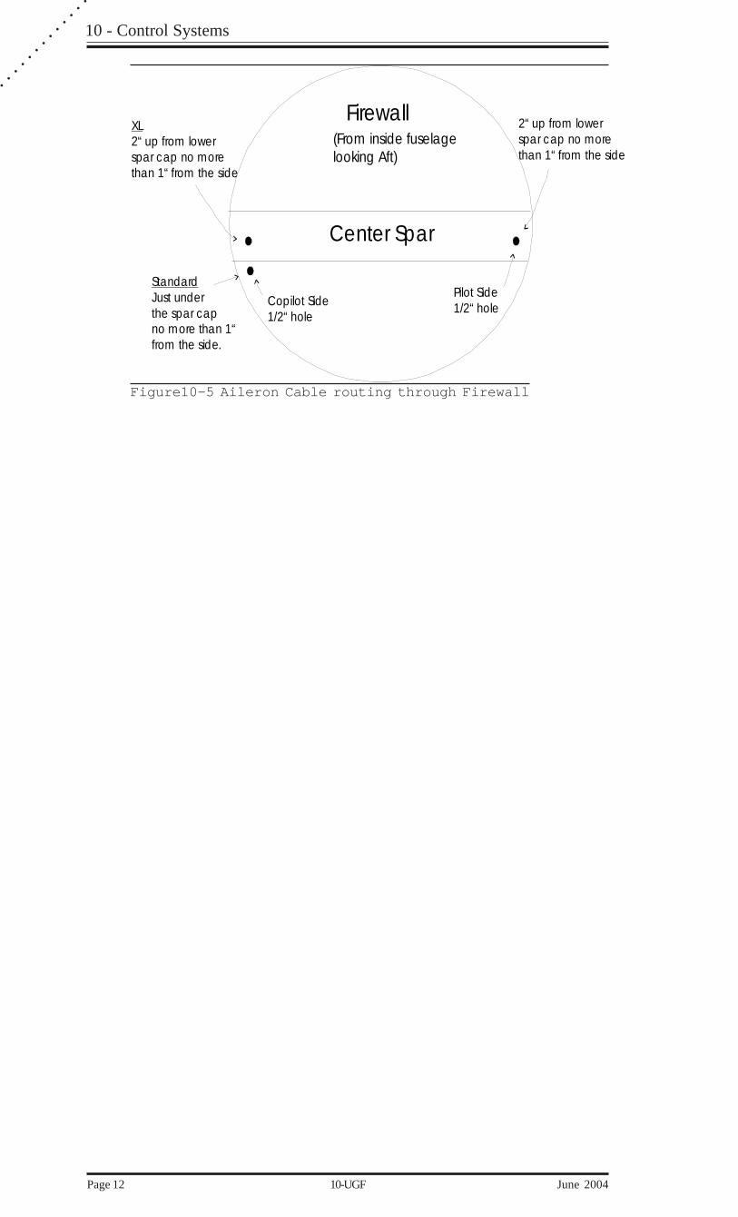
10.2 Rigging of the Roll System (Ailerons)To complete this portion of the project, the wings must be on the airframe.The first step isto install the aileron torque tubes to the ailerons. Remove the aileron from the wing andinstall the 3" long piece of 5/8" x .058 wall steel tube (VAUJ-01) as shown in Figure10-6.
Aileron
Trailing edge
Wing
3“ long piece of5/8“ x .058 wall steel tube
AN960-10L washerMS21042-3 nut
AN3-10A
Bolts run fore and aft to avoidinterference with upper and lowerwing skin.
~ 72“ length¾” aluminum tube
Drill hole with an 11/64“drill and ream to 3/16“
Make sure tube ends are cut straightand butted tight up against each other
Figure 10-6. Aileron Torque Tube Assembly.
Install the appropriate length of 3/4" aluminum tubing (VATT-01) to the other end of thesteel tube as shown. Attach with (2) AN3-10A bolts, (2) AN960-10L washers, and (2)MS21042-3 nuts.
Make sure that the bolts are oriented fore and aft with respect to the airframe. If they arenot, they will interfere with the upper and lower skins of the wings.
___ Once the bolts are in place, put in a couple of pop rivets for insurance.
___ Reinstall the aileron to the wing and check for any interference between the tube, and wingfoam. If any exists, a piece of tubing with sandpaper wrapped around it will take care of it.
Once the ailerons are in place, locate your bellcranks, aileron bearing brackets, and aile-ron cable bracket. Slide the bearing bracket onto the bellcrank and insert the bellcrankinto the torque tube. Fasten the bearing bracket to the flanges that you built for the cowl-to-wing joint. Slide the bracket into position, centering the torque tube in the hole in thewing root.
The aileron bearing bracket is a two piece installation. The bearing is located on the topsection. Bolt the top half to the bottom half with (2) AN3-5A bolts, (2) AN960-10 wash-ers and (2) MS21042-3 nuts as shown in figure 10-7 and 10;-8.
Copilot side first
To establish the depth of the bracket with regard to the wing root, you must install yourupper cowl and rotate the bellcrank to a 12 o’clock position (straight up). Give yourselfapproximately 1/2” clearance between the bellcrank and the cowl, and about 1/2” be-tween the bellcrank arm and the bearing. The aileron torque tube will probably need to betrimmed in order to achieve this.

10 - Control Systems
Page 14 10-UGF June 2004
○
○
○
○
○
○
○
○
○
○
○
○
○
___ Attach the aileron keel bellcrank support to the side of the fuselage using angle KBS.Holding angle KBS to the side of the fuselage under the support mark a spot to drill a holefor a 3/16” bolt. Drill both the angle and the support. Now you need to sand the side of theangle that touches the side of the fuselage and also sand the fuselage in this area.. Predrillthe angle and the side of the fuselage for (2) #10 sheet metal screws (Make sure yoursheet metal screws are short enough that you do not go through the outside fuselage skin.).Attach the angle to the side of the fuselage with a small amount of structural adhesive andthe sheet metal screws. Now you can use an AN3-5A bolt with (1) AN960-10 washerand (1) MS21402-3 nut.
Drill two holes in the keel 83” back from the canard bulkhead for a Standard or 88” aft foran XL on the floor of the Keel using a 1/2” drill bit. These holes will have to be elongatedforward and aft to allow the cables to enter the keel on an angle. Slide the aileron push-pullcables through these holes. Once they are in the keel you can put the MW-4 rod end andthe 1/4-28 jam nut on each cable. Note: (In the RG models make sure the cables stay onthe copilots side until they are past the hydraulic cylinder. This can be achieved by drillingtwo holes in the side of the keel and using a tie-wrap to hold the cables.) Clamp the cablesto the angle #KCA (one in front, one in back) using (2) AN3-6A bolts, (2) AN960-10Lwashers, and (2) MS21042-3 nuts. Use the clamps and shims provided. Attach the 2control cable rod ends to the Aileron Keel Bellcrank using (1) AN4-13A ,(2) AN970-4washers , (4) AN960-416 washers and (1) MS21042-4 nut. Refer to figure 10-4. Weare now going to mount Plate #KCA to the side of the keel. First you will need to find themiddle of your cable travel. Push the cable in as far as it will go on one end and mark thecable.
Pull the cable out and measure the distance between the mark and the end of the outersheath. Using a tape measurer place a mark at the midpoint. Do this to both cables at bothends. Adjust the cables so that they are on your midpoint mark. Adjust your Keel bellcrankso that it is in it’s neutral position. Refer to figure 10-4. Now place the KCA bracketagainst the copilots side of the keel and trace around it with a marker. Drill out two 3/16”holes in the keel and attach the KCA plate on the copilot side of keel using (2) MS24694S-59, (2) MS21042-3 and (4) AN960-10.
Drill two 1/2” holes in the firewall to allow the aileron cables to pass through it. Figure 10-5 show the proper locations. To get your cables through the 1/2” holes you will need totake off the rubber boots that protect the cables ends. You will also need to drill a hole inyour gear bulkhead or transverse bulkhead. This hole should be located to allow the cableto pass through this bulkhead and through the hole in the firewall smoothly.
To get all this into position, it might be necessary to shorten the torque tube once every-thing is in place.
___ First you will need to find the middle of your cable travel. Push the cable in as far as it willgo on one end and mark the cable.
Pull the cable out and measure the distance between the mark and the end of the outersheath. Using a tape measurer place a mark at the midpoint. Do this to both cables at bothends.
Clamp the keel bellcrank so that it is in it’s neutral position. The neutral position is wherethe middle mark on your cable is just showing at the end.
The idea is to get the cable centered, the rod ends screwed on to the middle oftheir travel while the aileron bellcrank and ailerons are neutral and the approachangles are 90 degrees. This will give you equal travel up and down. This alsogives the most travel up and down.

10 - Control Systems
June 2004 10-UGF Page 15
Clamp the ailerons so they cannot move from their neutral position.
At the wing root install the rod-ends on the end of the push/pull cables. Screw the rodends in all the way and back them out 4 complete turns. Attach the rod ends to the aileronbellcranks using an AN4-10A bolt, (2) AN960-416 washers, (1) AN970-4 large areawasher and an MS21042-4 locknut as shown in Figure 10-7.
Lightly clamp the aileron torque tube just outboard of the aileron bellcrank to keep theaileron bellcrank from turning. We will locate the cable clamp before we permanentlyinstall the aileron bellcrank. You will need two Cable Clamp angles and the cable Clampstrap. Position the Cable clamp angles on the wing flanges as shown in figure 10-7. Installthe cable clamp strap to the angles .
Hold the cable clamp up against the cable clamp strap and position it so that the cablesare as straight as possible and the approach angle to the aileron bellcrank is 90 degrees.Using small vise grip hold the cable clamps in position.
Drill two 3/16” holes and clamp the cable to the strap with (2) AN3-5A bolts, (2) AN960-10L washers, and (2) MS21042-3 nuts. Install the cable clamps and shims as shown infigure 10-7.
After the clamps are secured you can proceed to the aileron bellcranks.
To allow better access to the aileron torque tube bolts drill a 3/4” hole with a hole sawthrough both the flange and the aluminum bracket. Refer to figure 10-7. Center the holeup with the aileron torque tube and make sure you do not cut through the edge of theaileron bracket.
Double check that the approach angle is 90 degrees and the cables have their middlemarks right at the end of the outer sheath.
Using a small vise grip clamp the aileron bellcrank so it will not rotate when you startdrilling. With the vise grip holding the tubes you can carefully rotate the assembly andmake sure you are getting the proper aileron travels.
With a partner helping to keep you straight and perpendicular to the torque tube , use a 11/64” drill to drill a hole from top to bottom through the aileron torque tube.
Follow up with a 3/16” reamer.
Note: On the copilot side with the aileron in the neutral position The Bellcrank ispositioned approximately 30 degrees toward the firewall starting fromthe 12 o’clock (up) position.
Pilot side
To establish the depth of the bracket with regard to the wing root, you must installyour lower cowl and rotate the bellcrank to a 6 o’clock position (straight down).Give yourself approximately 1/2” clearance between the bellcrank and the cowl, andabout 1/2” between the bellcrank arm and the bearing. To get all this into position, itmight be necessary to shorten the torque tube once everything is in place.
___ Install the cable clamp strap and angles as you did on the copilots side . The cableclamp on the pilot side attaches to the strap below the wing. Allow about 3 “ of strapbelow the wing until the cable clamp is installed. You can trim it off after.
Note: With the pilot side aileron in the neutral position the bellcrank is posi-tioned approximately 30 degrees toward the firewall starting from the 6o’clock (down) position.
___ Check everything for free movement, eliminate any interferences.
___ Go back and clamp the trailing edge of the ailerons to the trailing edge of the wings. Makesure that the ailerons won’t move, and get set to install the aileron cables. This installationis done with the ailerons in the neutral position. If you have not attached the front rod endsof your aileron cables yet, do so now.

10 - Control Systems
Page 16 10-UGF June 2004
○
○
○
○
○
○
○
○
○
○
○
○
○
Note: When everything is hooked up properly, the top of the Yoke should pointat up aileron. I.E. When you turn the yoke to the right the right aileronwill be up and the left down.
If any binding occurs, check for misalignment in the cables, overtightened bolts, lack oflubrication, or misalignment of bearing to torque tube. When the Yoke is fully deflected,you should get at least 2" of deflection at the inboard trailing edge of the ailerons, both upand down. A properly rigged system will get approximately. 2-1/2” both up and down.
Any adjustments to achieve symmetry in aileron deflection should be done with threadedrod ends. Be careful to always use locknuts and that there is at least 1/4” of thread in therod end following any adjustments. The system will become smoother with use.
We have found that there is very little slack in the cables and that tiny bit goes away oncethe craft is in flight due to aerodynamic loading on the ailerons. If excess slop occurs, it isusually the result of sloppily drilled holes in mated components in the linkage between theailerons and stick. If you find a poor joint, either re-drill or ream the hole, and install anoversize close tolerance bolt. In the case that the hole is on a permanent assembly notused for dismantling the aircraft, put a couple of 1/8" pop rivets in to help out.
Note: Be aware that sloppy controls directly affect an aircraft’s VNE. Flutterusually starts in a control surface. Keep a close eye on the system. Ifsomething shows up that shouldn’t be there, investigate and repair priorto your next flight.

10 - Control Systems
June 2004 10-UGF Page 17
.
Figure 10-7 Aileron cable bracket assembly Co-Pilot side

10 - Control Systems
Page 18 10-UGF June 2004
○
○
○
○
○
○
○
○
○
○
○
○
○
Fla
ng
e
Bra
cke
t
Torq
ue
tu
be
AN
3-1
0A
bo
ltA
N9
60
-10
LM
S2
10
42
-3 lo
ckn
ut
AN
3-5
ABe llc ra nk
Cowl
MS2
46
93
S-2
72
fla
the
ad
sc
rew
(4
)A
N9
60
-10
L w
ash
er
(4)
MS2
10
42
-3 lo
ckn
ut
(4)
MS2
46
93
S-2
72
sc
rew
(4
)A
N9
60
-10
wa
she
r (4
)M
S2
10
42
-3 lo
ckn
ut
(4)
AN
3-1
0A
bo
ltA
N9
60
-10
LM
S2
10
42
-3 lo
ckn
ut
AN
3-5
A b
olt
AN
96
0-1
0L
wa
she
rM
S2
10
42
-3 lo
ckn
ut
Forw
ard
Ca
ble
cla
mp
Be
llcra
nk
3/4
“ h
ole
cu
t th
rou
gh
flan
ge
an
d a
lum
inu
mb
rac
ket
to a
llow
ac
ce
ssto
bo
lt
Win
g r
oo
tPilo
t Sid
e
Be
arin
g b
rac
ket
Forw
ard
90
de
gre
es
(ap
pro
ac
h a
ng
le)
AN
97
0-4
Larg
e a
rea
Sa
fety
wa
she
r
AN
4-1
0A
bo
ltM
S2
10
42
-4
loc
knu
t
AN
96
0-4
16
wa
she
rFe
ma
le r
od
-en
d
Be
llcra
nk
Be llc ran k
Sta
nda
rdC
ow
ling
Figure 10-8 Aileron cable bracket assembly Pilot side
10 - Control Systems
June 2004 10-UGF Page 19
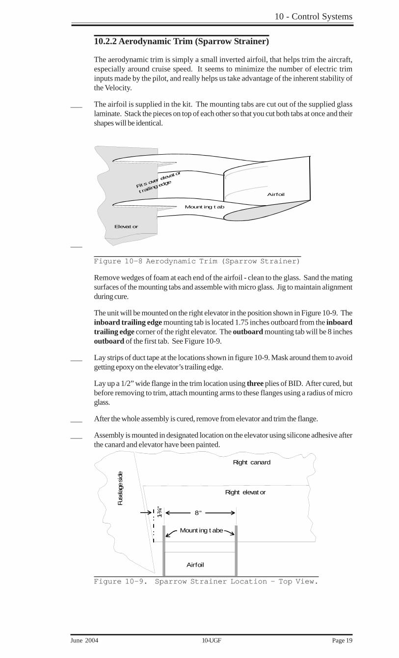
10.2.2 Aerodynamic Trim (Sparrow Strainer)
The aerodynamic trim is simply a small inverted airfoil, that helps trim the aircraft,especially around cruise speed. It seems to minimize the number of electric triminputs made by the pilot, and really helps us take advantage of the inherent stability ofthe Velocity.
___ The airfoil is supplied in the kit. The mounting tabs are cut out of the supplied glasslaminate. Stack the pieces on top of each other so that you cut both tabs at once and theirshapes will be identical.
___
Fit s over ele
vator
t railing edge
Mount ing t ab
Airfoil
Elevat or
Figure 10-8 Aerodynamic Trim (Sparrow Strainer)
Remove wedges of foam at each end of the airfoil - clean to the glass. Sand the matingsurfaces of the mounting tabs and assemble with micro glass. Jig to maintain alignmentduring cure.
The unit will be mounted on the right elevator in the position shown in Figure 10-9. Theinboard trailing edge mounting tab is located 1.75 inches outboard from the inboardtrailing edge corner of the right elevator. The outboard mounting tab will be 8 inchesoutboard of the first tab. See Figure 10-9.
___ Lay strips of duct tape at the locations shown in figure 10-9. Mask around them to avoidgetting epoxy on the elevator’s trailing edge.
Lay up a 1/2” wide flange in the trim location using three plies of BID. After cured, butbefore removing to trim, attach mounting arms to these flanges using a radius of microglass.
___ After the whole assembly is cured, remove from elevator and trim the flange.
___ Assembly is mounted in designated location on the elevator using silicone adhesive afterthe canard and elevator have been painted.
Right elevat or
Airfoil
Mount ing t abe
Fuse
lage
sid
e
Right canard
8“1-¾“
Figure 10-9. Sparrow Strainer Location - Top View.

10 - Control Systems
Page 20 10-UGF June 2004
○
○
○
○
○
○
○
○
○
○
○
○
○
10.2.3 - Elevator Trim
Locate a position for the trim spring that will not interfere with your radios or withyour control yokes. Slightly left of center will be the best spot. Now mark a 2” wideslot on the trailing edge of the canard that will go forward far enough to exposeapproximately 1/4” of foam. This will be the slot for the spring and bracket.
Snap the spring bracket onto the torque tube. Position the trim spring about 1/4”below the top of the canard cover and cut off the trim spring just above the little bendin the bracket. Remove this assembly and bolt the spring to the bracket using (2)MS27039-1-07 screws, AN970-3 washers on the spring side, and MS21042-3 lock-nuts. See fig 10-9
Snap the assembly back onto the torque tube and rotate it into the slot, Sanding asnecessary. Dig another 1/4” of foam and fill with micro-balloon to seal it off.
With the elevator T.E. all the way up (23-25 degrees), rotate the spring and bracketinto the slot.

10 - Control Systems
June 2004 10-UGF Page 21
Top
of F
usel
age
AN4-
14A
Bolt
MS2
1042
-4 N
ut
MS2
7039
-1-0
7 sc
rew
AN97
0-3
Was
her
MS2
1042
-3 N
ut
Shim
Long
Bra
cket
VAB-
02
Shor
tbr
acke
tVP
TB-0
1
Safe
ty b
lock
No
te
: P
lace
a w
oode
n sp
acer
bet
wee
n th
e bo
ttom
of t
he a
ctua
tor
whe
n it
is in
its f
ull a
ft (n
ose
up) p
ositio
n. S
ee F
igur
e 10
-2.
Use
silic
on to
atta
ch to
the
cana
rd.
This
will
prev
ent a
ctua
tor f
rom
jam
min
g el
evat
or if
trim
sprin
g br
eaks
.
Trim sprin
g
Alum
inum
Hard
poi
nt
AN52
6C-1
032R
8
Cut
trim
sprin
g ju
st ab
ove
bend
in th
e br
acke
t
Figure 10-10. Elevator Trim.
Torque t ube
1/8" pop rivet (Typ.)
MS27039-1-07 screwFiberglassTrim Spring
AN970-3 wide area washer
(Spring Side)
Figure 10-11
10.2.4 - Rudder Cable Installation
In the fuselage section, you installed the rudder cable conduits down each side of thefuselage, and in the wing section, you installed the conduits in the wings. Now it is time toinstall the actual cable in the conduit.

10 - Control Systems
Page 22 10-UGF June 2004
○
○
○
○
○
○
○
○
○
○
○
○
○
___ Run a length of your stainless steel cable down each side of the fuselage. Affix aNicopress sleeve and thimble to the rudder pedal end of each cable and attach themto the pedal ends. Leave yourself approximately. 12" of cable extending through thefirewall
___ Cut off the conduit so that it extends only about 1/4” aft of the firewall. Assemble thepulleys and the two angle brackets with AN3-6A bolts and MS21042-3 nuts.
___ Take a section of cable and run it the length of the wing. Put this length into the wingconduit and run it through. Trim the cable so that 12" extends out the winglet end, and 8"extends at the wing root.
Cana
rd B
ulkh
ead
1/16“ stainless steelrudder cable
Helper springfor rudder return
Spring attach tab onfuselage side
Nicopress sleeve
Rudder arm
AN111 Cable bushing
AN3-5ABolt
A 2 inch section of I-beamCut one side off of the I-beamInstall to fuselage side with Structural Adhesive and BSPS-4-41/8“ rivets
Figure 10-12. Rudder Cable to Rudder Pedal Attachment.Top of cent er sect ion spar
Bot t om of cent er sect ion spar
Cable uses t himble
No t himble used
Nicopress sleeve
Wingroot
5-minut e
SpringVCAS-01
Aluminum spring t abRivet s
Cot t er pin
Pulley at t aches wit h(4) ¾“ x 8 sheetmet al screws
Shroud adjust er,st art at secondhole from t op.
Figure 10-13. Wing Root Rudder Cable Assembly.
Cut the conduit flush with the winglet skin.
___ Tape the fuselage cable and wing cable together, and pull out the slack at the winglet end.
___ Position your pulley so that the cable comes through the firewall, around the pulley, andstraight towards the wing conduit. Move the pulley around to achieve best alignment.When you are satisfied with the pulley position, attach the fixture to the firewall with (4) 3/4 x #8 sheet metal screws. Install the small cotter pin as shown below to keep the cablefrom jumping track.
___ Install the rudder cable to the rudder bellcrank with a thimble and Nicopress sleeve. Theshroud adjuster is installed on the end of the fuselage cable with a Nicopress sleeve, nothimble is needed.
___ At the firewall end of the wing root rudder cable, install a thimble and Nicopress sleeve.This should fit tightly when attached to the second position on the shroud adjuster. Thisgives you one hole to loosen the system, and several to take up excess slack.

10 - Control Systems
June 2004 10-UGF Page 23
After some use, the system may need adjustment to achieve full rudder deployment.We have found that it is helpful to attach a small tension spring between the shroudadjuster and the wing root to assist the rudder return spring with the rudder pedalsthemselves. Rudders on the Velocity are not critical, and the aircraft can be operatedwithout them, but they sure come in handy during taxi and final approach.
* * *