control unit cpc 1-04 - digital information specific... · control unit cpc 1-04 ... 1.5 operator...
TRANSCRIPT
Chapter overview
Control unit CPC 1-04
1 Basic safety instructions 3. . . . . . . . . . . . . . . . . . . . . . . . . . . . . . . . . . . . . . . . . . 1.1 Intended use 3. . . . . . . . . . . . . . . . . . . . . . . . . . . . . . . . . . . . . . . . . . . . . . . . . . . . . . . . . . . . .
1.2 Working at the unit 3. . . . . . . . . . . . . . . . . . . . . . . . . . . . . . . . . . . . . . . . . . . . . . . . . . . . . . . .
1.3 Technical data 3. . . . . . . . . . . . . . . . . . . . . . . . . . . . . . . . . . . . . . . . . . . . . . . . . . . . . . . . . . . .
1.4 Transporting the unit 4. . . . . . . . . . . . . . . . . . . . . . . . . . . . . . . . . . . . . . . . . . . . . . . . . . . . . . .
1.5 Operator control elements 4. . . . . . . . . . . . . . . . . . . . . . . . . . . . . . . . . . . . . . . . . . . . . . . . . .
2 Structure and functions 5. . . . . . . . . . . . . . . . . . . . . . . . . . . . . . . . . . . . . . . . . . . . 2.1 Complete unit 5. . . . . . . . . . . . . . . . . . . . . . . . . . . . . . . . . . . . . . . . . . . . . . . . . . . . . . . . . . . . .
2.2 Control panel 6. . . . . . . . . . . . . . . . . . . . . . . . . . . . . . . . . . . . . . . . . . . . . . . . . . . . . . . . . . . . .
2.3 Functions 7. . . . . . . . . . . . . . . . . . . . . . . . . . . . . . . . . . . . . . . . . . . . . . . . . . . . . . . . . . . . . . . .
2.4 Control consoles 7. . . . . . . . . . . . . . . . . . . . . . . . . . . . . . . . . . . . . . . . . . . . . . . . . . . . . . . . . .
3 Buttons, pictograms, overviews 8. . . . . . . . . . . . . . . . . . . . . . . . . . . . . . . . . . . . 3.1 Control panel buttons 8. . . . . . . . . . . . . . . . . . . . . . . . . . . . . . . . . . . . . . . . . . . . . . . . . . . . . .
3.2 Pictograms/symbols in the display 9. . . . . . . . . . . . . . . . . . . . . . . . . . . . . . . . . . . . . . . . . . .
3.3 Commands general 17. . . . . . . . . . . . . . . . . . . . . . . . . . . . . . . . . . . . . . . . . . . . . . . . . . . . . . .
4 Job memory card 19. . . . . . . . . . . . . . . . . . . . . . . . . . . . . . . . . . . . . . . . . . . . . . . . . .
5 Switching on and off 21. . . . . . . . . . . . . . . . . . . . . . . . . . . . . . . . . . . . . . . . . . . . . . 5.1 Switching on 21. . . . . . . . . . . . . . . . . . . . . . . . . . . . . . . . . . . . . . . . . . . . . . . . . . . . . . . . . . . . . .
5.2 Switching off 21. . . . . . . . . . . . . . . . . . . . . . . . . . . . . . . . . . . . . . . . . . . . . . . . . . . . . . . . . . . . . .
6 Production run display 22. . . . . . . . . . . . . . . . . . . . . . . . . . . . . . . . . . . . . . . . . . . .
7 Basic display 25. . . . . . . . . . . . . . . . . . . . . . . . . . . . . . . . . . . . . . . . . . . . . . . . . . . . . 7.1 Automatic register control 26. . . . . . . . . . . . . . . . . . . . . . . . . . . . . . . . . . . . . . . . . . . . . . . . . .
7.2 Follow–up functions 28. . . . . . . . . . . . . . . . . . . . . . . . . . . . . . . . . . . . . . . . . . . . . . . . . . . . . . .
8 Malfunction display 30. . . . . . . . . . . . . . . . . . . . . . . . . . . . . . . . . . . . . . . . . . . . . . .
9 Service display 35. . . . . . . . . . . . . . . . . . . . . . . . . . . . . . . . . . . . . . . . . . . . . . . . . . . . 9.1 SERVICE DISPLAY main menu 35. . . . . . . . . . . . . . . . . . . . . . . . . . . . . . . . . . . . . . . . . . . . .
9.2 Software versions 36. . . . . . . . . . . . . . . . . . . . . . . . . . . . . . . . . . . . . . . . . . . . . . . . . . . . . . . . .
9.3 Service functions 36. . . . . . . . . . . . . . . . . . . . . . . . . . . . . . . . . . . . . . . . . . . . . . . . . . . . . . . . . .

Chapter overview
10 Characteristic curves 38. . . . . . . . . . . . . . . . . . . . . . . . . . . . . . . . . . . . . . . . . . . . . . 10.1 Types of characteristic curves 38. . . . . . . . . . . . . . . . . . . . . . . . . . . . . . . . . . . . . . . . . . . . . .
10.2 Change characteristic curves 40. . . . . . . . . . . . . . . . . . . . . . . . . . . . . . . . . . . . . . . . . . . . . . .
10.3 Speed–compensated characteristic curves 45. . . . . . . . . . . . . . . . . . . . . . . . . . . . . . . . . . .
10.4 Characteristic curves for manipulated ink zone variables from area coverage values 47
10.5 Store/load characteristic curves 48. . . . . . . . . . . . . . . . . . . . . . . . . . . . . . . . . . . . . . . . . . . . .
10.6 Calibration of press 51. . . . . . . . . . . . . . . . . . . . . . . . . . . . . . . . . . . . . . . . . . . . . . . . . . . . . . . .
11 Data transfer 54. . . . . . . . . . . . . . . . . . . . . . . . . . . . . . . . . . . . . . . . . . . . . . . . . . . . . . 11.1 Overview 54. . . . . . . . . . . . . . . . . . . . . . . . . . . . . . . . . . . . . . . . . . . . . . . . . . . . . . . . . . . . . . . .
11.2 Current job in press memory 58. . . . . . . . . . . . . . . . . . . . . . . . . . . . . . . . . . . . . . . . . . . . . . . .
11.3 Job in job memory 60. . . . . . . . . . . . . . . . . . . . . . . . . . . . . . . . . . . . . . . . . . . . . . . . . . . . . . . . .
11.4 Job on job memory card, formatting of job memory card 62. . . . . . . . . . . . . . . . . . . . . . . .
12 Job preparation 64. . . . . . . . . . . . . . . . . . . . . . . . . . . . . . . . . . . . . . . . . . . . . . . . . . . 12.1 Select memory location 64. . . . . . . . . . . . . . . . . . . . . . . . . . . . . . . . . . . . . . . . . . . . . . . . . . . .
12.2 Display selection menu GLOBAL PRESS 65. . . . . . . . . . . . . . . . . . . . . . . . . . . . . . . . . . . .
12.3 Enter job name 66. . . . . . . . . . . . . . . . . . . . . . . . . . . . . . . . . . . . . . . . . . . . . . . . . . . . . . . . . . .
12.4 Sheet reversing device - switching on and off, change colour 67. . . . . . . . . . . . . . . . . . . .
12.5 Colour allocation 71. . . . . . . . . . . . . . . . . . . . . . . . . . . . . . . . . . . . . . . . . . . . . . . . . . . . . . . . . .
12.6 Allocate characteristic curves 74. . . . . . . . . . . . . . . . . . . . . . . . . . . . . . . . . . . . . . . . . . . . . . .
12.7 Varnish allocation 75. . . . . . . . . . . . . . . . . . . . . . . . . . . . . . . . . . . . . . . . . . . . . . . . . . . . . . . . .
12.8 Allocate characteristic curves for varnishes 78. . . . . . . . . . . . . . . . . . . . . . . . . . . . . . . . . .
12.9 Allocate characteristic curves from the plate image reader to a colour 79. . . . . . . . . . . .
12.10 Format limitation 80. . . . . . . . . . . . . . . . . . . . . . . . . . . . . . . . . . . . . . . . . . . . . . . . . . . . . . . . .
12.11 Ink fountain roller and register functions, light pen 82. . . . . . . . . . . . . . . . . . . . . . . . . . . .
13 Positioning 84. . . . . . . . . . . . . . . . . . . . . . . . . . . . . . . . . . . . . . . . . . . . . . . . . . . . . . .
14 Ink shut–off 85. . . . . . . . . . . . . . . . . . . . . . . . . . . . . . . . . . . . . . . . . . . . . . . . . . . . . . .
Index 87. . . . . . . . . . . . . . . . . . . . . . . . . . . . . . . . . . . . . . . . . . . . . . . . . . . . . . . . . . . . .
CPC 1-04
3
1 Basic safety instructions
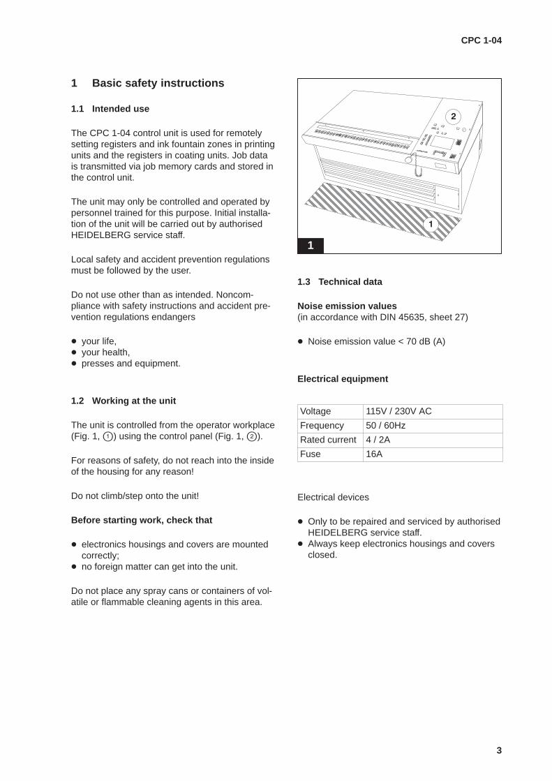
1.1 Intended use
The CPC 1-04 control unit is used for remotelysetting registers and ink fountain zones in printingunits and the registers in coating units. Job datais transmitted via job memory cards and stored inthe control unit.
The unit may only be controlled and operated bypersonnel trained for this purpose. Initial installa-tion of the unit will be carried out by authorisedHEIDELBERG service staff.
Local safety and accident prevention regulationsmust be followed by the user.
Do not use other than as intended. Noncom-pliance with safety instructions and accident pre-vention regulations endangers
� your life,� your health,� presses and equipment.
1.2 Working at the unit
The unit is controlled from the operator workplace(Fig. 1, �) using the control panel (Fig. 1, �).
For reasons of safety, do not reach into the insideof the housing for any reason!
Do not climb/step onto the unit!
Before starting work, check that
� electronics housings and covers are mountedcorrectly;
� no foreign matter can get into the unit.
Do not place any spray cans or containers of vol-atile or flammable cleaning agents in this area.
1
ÈÈÈÈÈÈÈÈÈÈÈÈÈÈÈÈÈÈÈÈÈÈÈÈÈÈÈÈÈÈÈÈÈÈÈÈÈÈÈÈÈÈÈÈÈÈÈÈÈÈÈÈÈÈÈÈÈÈÈÈ
1.3 Technical data
Noise emission values(in accordance with DIN 45635, sheet 27)
� Noise emission value < 70 dB (A)
Electrical equipment
Voltage 115V / 230V AC
Frequency 50 / 60Hz
Rated current 4 / 2A
Fuse 16A
Electrical devices
� Only to be repaired and serviced by authorisedHEIDELBERG service staff.
� Always keep electronics housings and coversclosed.
CPC 1-04
4
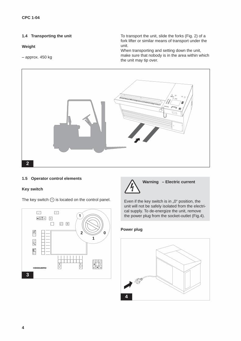
1.4 Transporting the unit
Weight
– approx. 450 kg
To transport the unit, slide the forks (Fig. 2) of afork lifter or similar means of transport under theunit.When transporting and setting down the unit,make sure that nobody is in the area within whichthe unit may tip over.
2
1.5 Operator control elements
Key switch
The key switch � is located on the control panel.
3
0 1
2
Warning – Electric current
Even if the key switch is in „0“ position, theunit will not be safely isolated from the electri-cal supply. To de-energize the unit, removethe power plug from the socket-outlet (Fig.4).
Power plug
4
CPC 1-04
5
2 Structure and functions
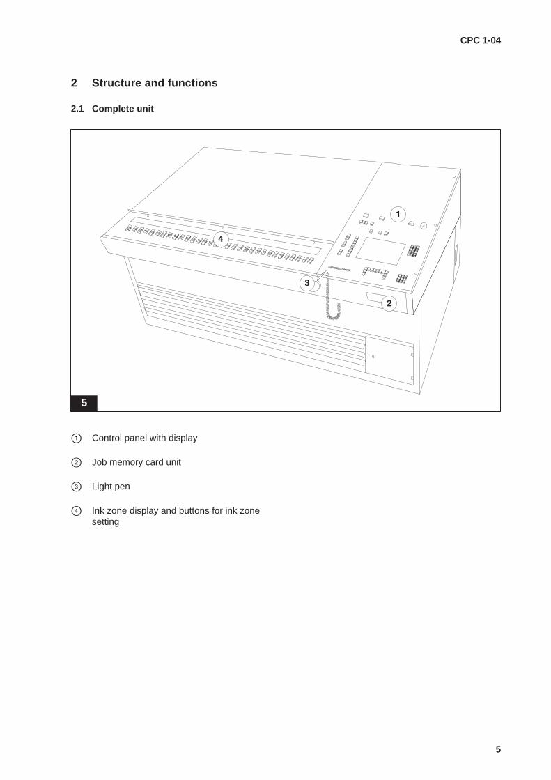
2.1 Complete unit
5
� Control panel with display
� Job memory card unit
� Light pen
� Ink zone display and buttons for ink zonesetting

CPC 1-04
6
2.2 Control panel
6
01
2
ENTER DELETE MALFUNCTION
BASIC
GLOBAL PRINTING UNIT
DISPLAY
MALFUNCTIONDISPLAY
SERVICEDISPLAY
FINE DISPLAYINK FOUNTAIN
FUNCTION
SETTING
INKSHUT–OFF
PRODUCTION RUN
DATATRANSFER
JOBPREPARATION
POSITIO-NING
FINE DISPLAY
1 2 3
4 5 6
7 8 9
0ABC DEF GHI
JKL MNO PQR
ST UVW XYZ
. /
D.S. O.S.
ZONES
DISPLAY
� Key switch
� Signal lamp
� Command control buttonsENTERDELETE
� Command buttonsDATA TRANSFERJOB PREPARATIONPOSITIONINGINK SHUT–OFF
� „Unit“ selector buttonsSWITCHOVERGLOBALPRINTING UNIT
� „Group“ selector buttons
� Display buttonsPRODUCTION RUN DISPLAYBASIC DISPLAYMALFUNCTION DISPLAYSERVICE DISPLAYFINE DISPLAY INK FOUNTAIN ZONESFINE DISPLAY
� Function buttons
� Adjustment buttons (+/–)
� Register keypadCircumferential registerLateral registerDiagonal register
Alphanumeric keypad
Control console display (ZID)
CPC 1-04
7
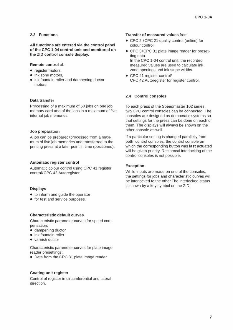
2.3 Functions
All functions are entered via the control panelof the CPC 1-04 control unit and monitored onthe ZID control console display.
Remote control of:
� register motors,� ink zone motors,� ink fountain roller and dampening ductor
motors.
Data transferProcessing of a maximum of 50 jobs on one jobmemory card and of the jobs in a maximum of fiveinternal job memories.
Job preparationA job can be prepared/processed from a maxi-mum of five job memories and transferred to theprinting press at a later point in time (positioned).
Automatic register controlAutomatic colour control using CPC 41 registercontrol /CPC 42 Autoregister.
Displays� to inform and guide the operator� for test and service purposes.
Characteristic default curvesCharacteristic parameter curves for speed com-pensation:� dampening ductor� ink fountain roller� varnish ductor
Characteristic parameter curves for plate imagereader presettings:� Data from the CPC 31 plate image reader
Coating unit registerControl of register in circumferential and lateraldirection.
Transfer of measured values from
� CPC 2 /CPC 21 quality control (online) forcolour control;
� CPC 3/CPC 31 plate image reader for preset-ting data.In the CPC 1-04 control unit, the recordedmeasured values are used to calculate inkzone openings and ink stripe widths.
� CPC 41 register control/CPC 42 Autoregister for register control.
2.4 Control consoles
To each press of the Speedmaster 102 series,two CPC control consoles can be connected. Theconsoles are designed as democratic systems sothat settings for the press can be done on each ofthem. The displays will always be shown on theother console as well.
If a particular setting is changed parallelly fromboth control consoles, the control console onwhich the corresponding button was last actuatedwill be given priority. Reciprocal interlocking of thecontrol consoles is not possible.
Exception:While inputs are made on one of the consoles,the settings for jobs and characteristic curves willbe interlocked to the other.The interlocked statusis shown by a key symbol on the ZID.
CPC 1-04
8
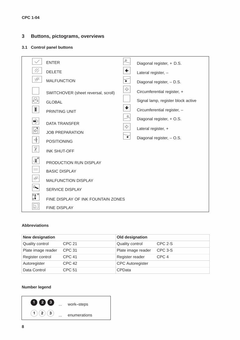
3 Buttons, pictograms, overviews
3.1 Control panel buttons
ENTER
DELETE
MALFUNCTION
SWITCHOVER (sheet reversal, scroll)
GLOBAL
PRINTING UNIT
DATA TRANSFER
JOB PREPARATION
POSITIONING
INK SHUT-OFF
PRODUCTION RUN DISPLAY
BASIC DISPLAY
MALFUNCTION DISPLAY
SERVICE DISPLAY
FINE DISPLAY OF INK FOUNTAIN ZONES
FINE DISPLAY
Diagonal register, + D.S.
Lateral register, –
Diagonal register, – D.S.
Circumferential register, +
Circumferential register, –
Diagonal register, + O.S.
Lateral register, +
Diagonal register, – O.S.
Signal lamp, register block active
Abbreviations
New designation Old designation
Quality control CPC 21 Quality control CPC 2-S
Plate image reader CPC 31 Plate image reader CPC 3-S
Register control CPC 41 Register reader CPC 4
Autoregister CPC 42 CPC Autoregister
Data Control CPC 51 CPData
Number legend
... work–steps
... enumerations

CPC 1-04
9
3.2 Pictograms/symbols in the display
BASIC DISPLAY
PRODUCTION RUN DISPLAY
Switch automatic register control to active
Diagonal register D.S.
Lateral register
Register display zero
Percentage setting of ink fountain zones
Setting of ink fountain roller
Circumferential register
Diagonal register O.S.
Setting of dampening ductor/varnish ductor
Total mode
Display automatic register control active
Display ink fountain zone setting active
Automatic register control selection
Disable/switch on circumferential register
Disable/switch on lateral register
Standard colour for CPC 42 Autoregister
Disable/switch on diagonal register
Total mode
Delete
Operation automatic register control
Follow-up functions selection
Automatic follow-up control
Follow-up control
Total mode
Selection confirmation
Dead beat
Correction values zero
Automatic follow-up control active
CPC 1-04
10
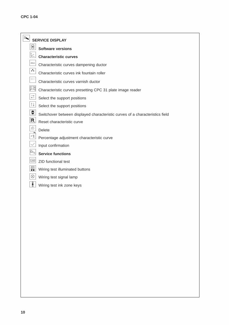
SERVICE DISPLAY
Characteristic curves ink fountain roller
Characteristic curves dampening ductor
Characteristic curves
Software versions
Characteristic curves varnish ductor
Characteristic curves presetting CPC 31 plate image reader
Delete
Percentage adjustment characteristic curve
Input confirmation
Service functions
Select the support positions
Select the support positions
Reset characteristic curve
Switchover between displayed characteristic curves of a characteristics field
ZID ZID functional test
Wiring test illuminated buttons
Wiring test signal lamp
Wiring test ink zone keys

CPC 1-04
11
Current job in press memory
Command DATA TRANSFER
Job in job memory
Read job from job memory card
Combine jobs
Copy to one of the 50 memory locations on the job memory card
Delete job
Select job memory card
Format the job memory card
Define job memory
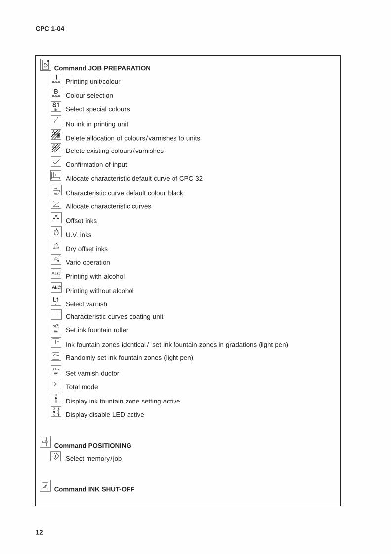
Command JOB PREPARATION
Select memory/ job
Format limitation
Alphanumeric keypad
Colour allocation
Press configuration
Name job memory
Input using letters
Sheet reversal
Copy job to one of the 5 job memories
Switchover straight printing/perfecting
Change colour
Store all characteristic curves of the ink fountain roller type
Store all characteristic curves of the dampening ductor type
Store all characteristic curves of the varnish ductor type
Store all characteristic curves of the colour presetting type
Store characteristic curve of the dead beat type
Store characteristic curve of the CPC 2 follow-up control display type
Store characteristic curve of the preinking type
Scroll
Store all characteristic curves
CPC 1-04
12
Command JOB PREPARATION
Ink fountain zones identical / set ink fountain zones in gradations (light pen)
Command INK SHUT-OFF
Command POSITIONING
Randomly set ink fountain zones (light pen)
Set varnish ductor
Total mode
Display ink fountain zone setting active
Set ink fountain roller
Printing unit/colour
Colour selection
Select special colours
No ink in printing unit
Allocate characteristic default curve of CPC 32
Select varnish
Delete allocation of colours/varnishes to units
Delete existing colours/varnishes
Confirmation of input
Allocate characteristic curves
Offset inks
U.V. inks
Dry offset inks
Vario operation
Printing with alcohol
Printing without alcohol
Characteristic curves coating unit
Display disable LED active
Select memory/ job
Characteristic curve default colour blackBLA

CP
C 1-0413
CP
C 1-04 C
omm
unicationCPC 1–04 Communication
1...5
Job memory
PRODUCTION RUN DISPLAY
BASIC DISPLAY
PREPARATION
ÎÎ
ÎÎ
ÎÎ
ÎÎ
ÎÎ
ÎÎ ÎÎ
ÎÎ
ÎÎ
ÎÎ
ÎÎ
ÎÎ
1...50
A
Press
12
34
5
INK SHUT–OFF
automatic
automatic
DATA TRANSFER(copying)
POSITIONING(copying)
DATA TRANSFER(copying)
memory
DATA TRANSFER(copying)
Copying via CPTronic
CPC 1-04Data ControlCPC 51
CPTronicCopying via
JOB
CPC 1-04
14
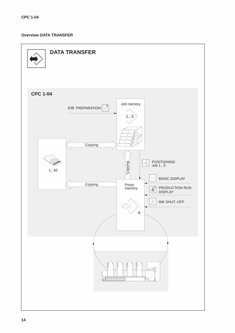
Overview DATA TRANSFER
DATA TRANSFER
1...5
CPC 1-04
Job memory
PRODUCTION RUN
BASIC DISPLAY
PREPARATION
ÎÎÎÎÎÎÎÎÎ ÎÎÎÎÎ
POSITIONING
Copying
1...50
A
Cop
ying Job 1...5
12
34
5
INK SHUT–OFF
Copying
Pressmemory
DISPLAY
JOB
CPC 1-04
15
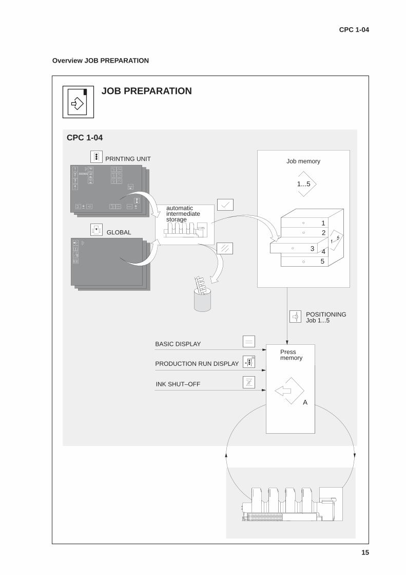
Overview JOB PREP ARATION
1...5
Job memory
12
3
5
JOB PREPARATION
CPC 1-04
ÎÎÎÎÎÎ
ÎÎÎÎÎÎÎ
A
Press
PRODUCTION RUN DISPLAY
BASIC DISPLAY
INK SHUT–OFF
4
memory
automaticintermediate
GLOBAL
PRINTING UNIT
POSITIONINGJob 1...5
300965
storage
CPC 1-04
16
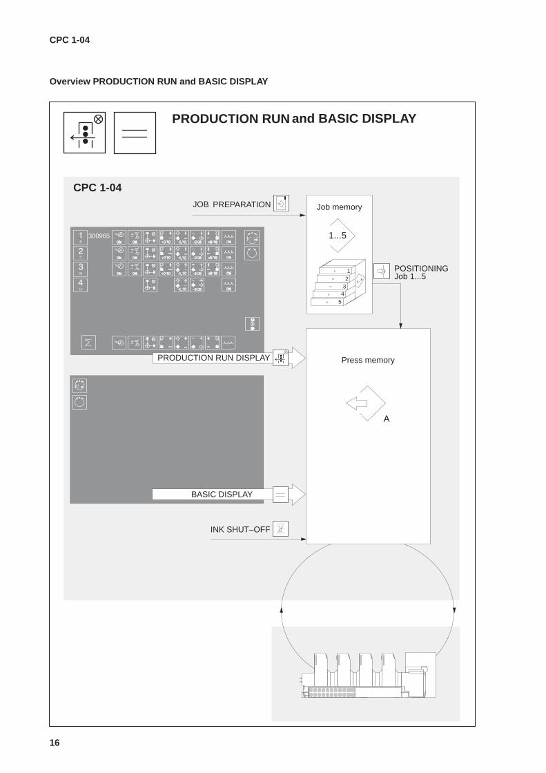
Overview PRODUCTION RUN and BASIC DISPLAY
PRODUCTION RUN
CPC 1-04
1...5
Job memoryPREPARATION
12
34
5
ÎÎÎÎÎÎÎ
ÎÎÎÎÎÎ
A
Press memory
POSITIONINGJob 1...5
INK SHUT–OFF
and BASIC DISPLAY
BASIC DISPLAY
300965
PRODUCTION RUN DISPLAY
JOB

CPC 1-04
17
3.3 Commands general
7
ABC DEF GHI
JKL MNO PQR
ST UVW XYZ
. /
Commands (Fig. 7, �) can be selected when thekey switch (Fig. 7, �) is in the unlocked state(position 1), irrespective of the current display.However, this is only possible if no othercommand is being processed at the same time.
Command initialization
8
ABC DEF GHI
JKL MNO PQR
ST UVW XYZ
. /
Upon selection of a command (Fig. 8, �) all dis-plays are removed and the command control but-ton ENTER (Fig. 8, �) flashes. Depending on thecommand, press groups and printing unit groupsare preselected in the display. Preselections canbe changed.
Command functions
9
ABC DEF GHI
JKL MNO PQR
ST UVW XYZ
. /
10
Depending on the preselection, the functiongroups and printing unit groups will appear forwhich the command can now be selected moreprecisely.
Command selection is effected using:
� the selector buttons ’Group’ (Fig. 9, �),� the +/- adjustment buttons (Fig. 9, �),� the numeric keypad (Fig. 9, �),� the register keypad (Fig. 9, �) or� the light pen (Fig. 10).

CPC 1-04
18
Command correction and commandinterruption
11
ABC DEF GHI
JKL MNO PQR
ST UVW XYZ
. /
Corrections to the command selection are inputafter reselection (Fig. 11, �).Any desired interruptions during command selec-tion can be made by selecting the PRODUCTIONRUN, BASIC, MALFUNCTION or SERVICE DIS-PLAY (Fig. 11, �).The command control button Enter switches offand the command button flashes. To return to thecommand, press the flashing command button(Fig. 11, �).
Enable command
12
ABC DEF GHI
JKL MNO PQR
ST UVW XYZ
. /
All commands are enabled using the commandcontrol button ENTER (Fig. 12, �).Upon actuation, the Enter button will light up untilthe command has been executed.
Command execution not possible
13
ABC DEF GHI
JKL MNO PQR
ST UVW XYZ
. /
If the command cannot be executed at all or onlyincompletely, the signal lamp (Fig. 13, �) willlight up.In order for the command to be carried out again,the cause of the malfunction must be eliminatedand the command re-initialized.
Aborting a command
14
ABC DEF GHI
JKL MNO PQR
ST UVW XYZ
. /
Commands are aborted by pressing the com-mand control button DELETE (Fig. 14, �).
Actuation prior to enabling via the commandcontrol button ENTER:Return to the display selected before the com-mand was initialized.
Actuation after enabling via the command controlbutton ENTER:Abortion of command execution in the currentactual status.
CPC 1-04
19
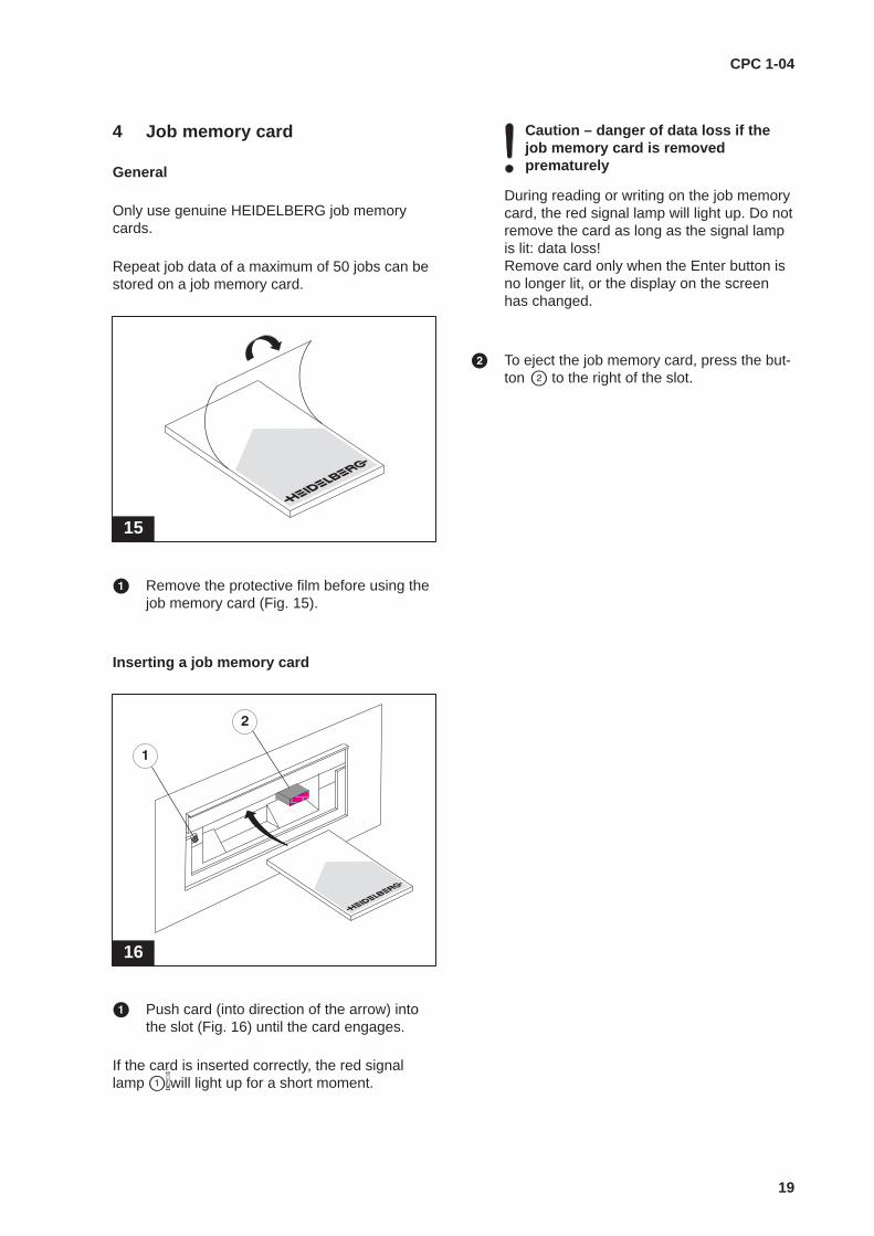
4 Job memory card
General
Only use genuine HEIDELBERG job memorycards.
Repeat job data of a maximum of 50 jobs can bestored on a job memory card.
15
� Remove the protective film before using thejob memory card (Fig. 15).
Inserting a job memory card
16
ÁÁ
� Push card (into direction of the arrow) intothe slot (Fig. 16) until the card engages.
If the card is inserted correctly, the red signallamp ��will light up for a short moment.
Caution – danger of data loss if thejob memory card is removed prematurely
During reading or writing on the job memorycard, the red signal lamp will light up. Do notremove the card as long as the signal lampis lit: data loss!Remove card only when the Enter button isno longer lit, or the display on the screenhas changed.
� To eject the job memory card, press the but-ton � to the right of the slot.

CPC 1-04
20
Master for copying contents of job memory card
1 26
2 27
3 28
4 29
5 30
6 31
7 32
8 33
9 34
10 35
11 36
12 37
13 38
14 39
15 40
16 41
17 42
18 43
19 44
20 45
21 46
22 47
23 48
24 49
25 50
CPC 1-04
21
5 Switching on and off
5.1 Switching on
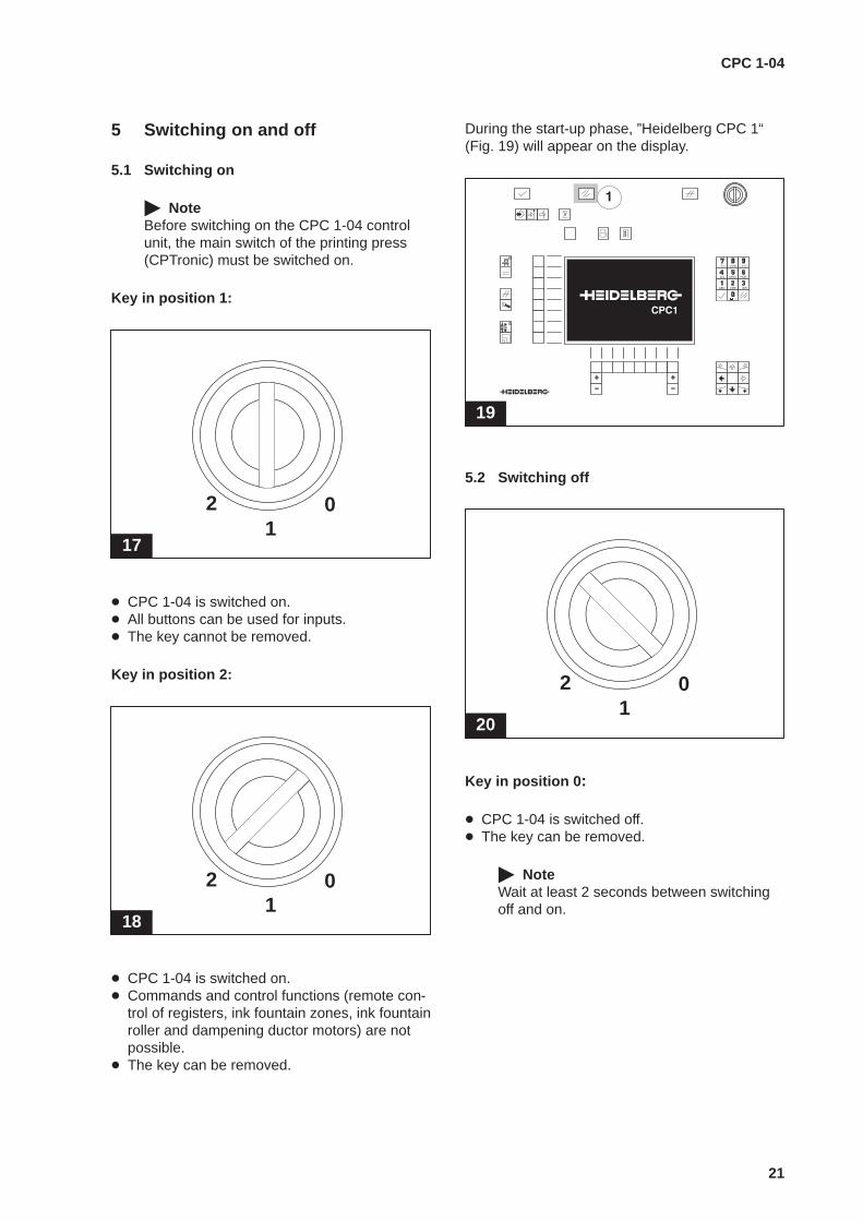
� NoteBefore switching on the CPC 1-04 controlunit, the main switch of the printing press(CPTronic) must be switched on.
Key in position 1:
17
01
2
� CPC 1-04 is switched on.� All buttons can be used for inputs.� The key cannot be removed.
Key in position 2:
18
01
2
� CPC 1-04 is switched on.� Commands and control functions (remote con-
trol of registers, ink fountain zones, ink fountainroller and dampening ductor motors) are notpossible.
� The key can be removed.
During the start-up phase, ”Heidelberg CPC 1“(Fig. 19) will appear on the display.
19
ABC DEF GHI
JKL MNO PQR
ST UVW XYZ
. /
5.2 Switching off
20
01
2
Key in position 0 :
� CPC 1-04 is switched off.� The key can be removed.
� NoteWait at least 2 seconds between switchingoff and on.
CPC 1-04
22
6 Production run display
21
01
2
1 2 3
4 5 6
7 8 9
0ABC DEF GHI
JKL MNO PQR
ST UVW XYZ
. /
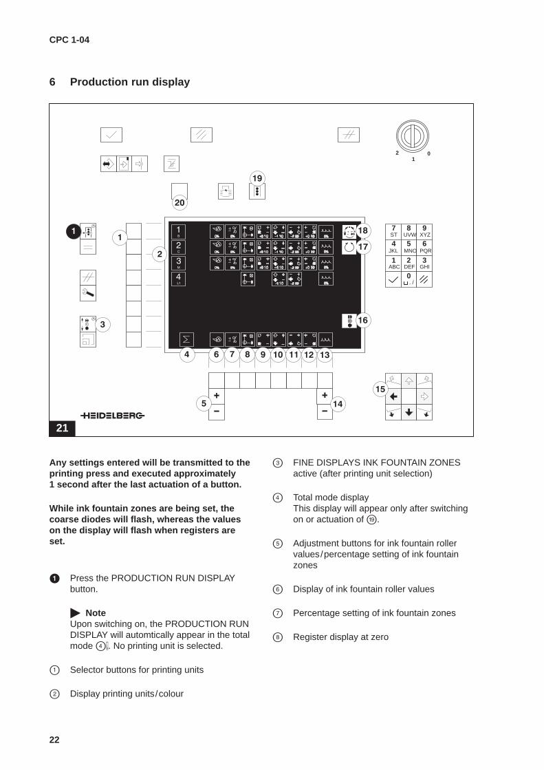
Any settings entered will be transmitted to theprinting press and executed approximately 1 second after the last actuation of a button.
While ink fountain zones are being set, thecoarse diodes will flash, whereas the valueson the display will flash when registers areset.
� Press the PRODUCTION RUN DISPLAYbutton.
� NoteUpon switching on, the PRODUCTION RUNDISPLAY will automtically appear in the totalmode ��. No printing unit is selected.
� Selector buttons for printing units
� Display printing units/colour
� FINE DISPLAYS INK FOUNTAIN ZONESactive (after printing unit selection)
� Total mode display This display will appear only after switchingon or actuation of .
� Adjustment buttons for ink fountain roller values/percentage setting of ink fountainzones
� Display of ink fountain roller values
� Percentage setting of ink fountain zones
� Register display at zero

CPC 1-04
23
Upon selection of a register ���... using thefunction buttons, the button in the center ofthe register block � will light up.
If the diagonal register is set, the values forthe circumferential register will automaticallybe corrected.
� Display diagonal register D.S.
� Display circumferential register
Display lateral register
Display diagonal register O.S.
� Display dampening values/varnish values
Adjustment buttons dampening values/var-nish values
� Adjustment buttons register (register block)
� Display ink zone setting active (after printingunit selection)
� Display automatic follow-up control active
� Display automatic register control active
� Selector button PRINTING UNITTotal mode (all printing units selected)
� The function button�SWITCHOVER is usedto change between the previously selectedprinting unit groups (before/after the setsheet reversal).
Setting of ink fountain zones in groups
22
Ink fountain zones can be set in groups. However,only ink fountain zones which directly follow oneanother can be selected as a group.
� Select the production run display (Fig. 22),activate a printing unit � and press the but-ton ”Percentage setting of ink fountainzones“ �.
The diodes for the selected printing unit will lightup in the ink zone display, in accordance with theopening value for the associated ink fountainzones.
� Use the ”–“ buttons below the light-emittingdiodes to define the required range.
Example:Select ink fountain zones 9 to 13; press the”–“ buttons below the ink fountain zones 9 to13 (one after the other). The disable diodesin the selected range will not light up.
� Set the selected ink fountain zones in theproduction run display, using the left-handside +/– buttons (see page 22, �).

CPC 1-04
24

CPC 1-04
25
7 Basic display
23
01
2
1 2 3
4 5 6
7 8 9
0ABC DEF GHI
JKL MNO PQR
ST UVW XYZ
. /
Input functions are transmitted directly to theprinting press where they are carried out.
� Press the BASIC DISPLAY button (buttonlights up).
� Press the AUTOMATIC REGISTER CONTROL (CPC 41/CPC 42) button (see page 26).
� Press the FOLLOW-UP FUNCTIONS (CPC 2/CPC 21) button (see page 28).

CPC 1-04
26
7.1 Automatic register control
24
01
2
1 2 3
4 5 6
7 8 9
0ABC DEF GHI
JKL MNO PQR
ST UVW XYZ
. /
Automatic register control with CPC 41 regis-ter control or CPC 42 Autoregister . Uponpressing the Run ��function button, inputswill be transmitted directly to the printingpress where they are carried out.
� NoteFor a detailed description see the CPC 42Autoregister operating instructions , Chapter”Operation“ (this file).
� Select the printing units(default: total mode)
� Total mode Will only appear if all printing units havebeen selected (upon switching on of the au-tomatic register control or actuating �).
� Automatic register controlAfter individual printing units ��have beenselected for automatic register control, usethe automatic register control button � forconfirmation.
CPC 1-04
27
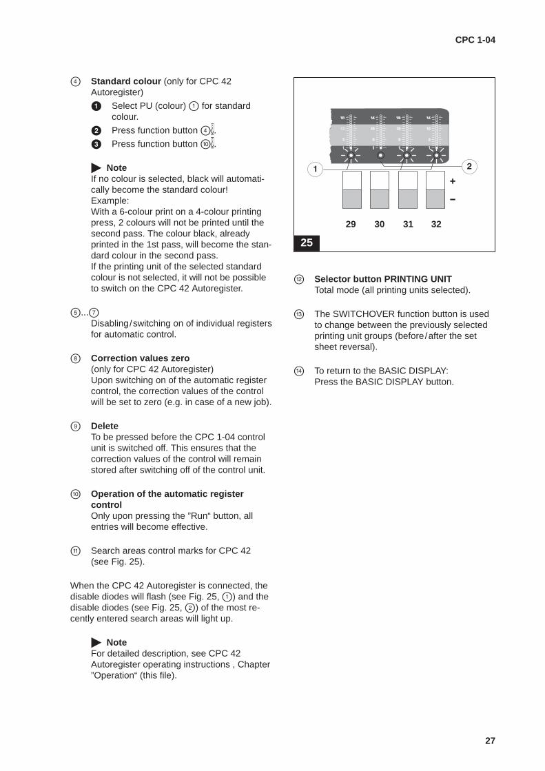
� Standard colour (only for CPC 42Autoregister)
� Select PU (colour) � for standardcolour.
� Press function button ��.
� Press function button ��.
� NoteIf no colour is selected, black will automati-cally become the standard colour!Example:With a 6-colour print on a 4-colour printingpress, 2 colours will not be printed until thesecond pass. The colour black, alreadyprinted in the 1st pass, will become the stan-dard colour in the second pass.If the printing unit of the selected standardcolour is not selected, it will not be possibleto switch on the CPC 42 Autoregister.
�...�Disabling/switching on of individual registersfor automatic control.
� Correction values zero (only for CPC 42 Autoregister) Upon switching on of the automatic registercontrol, the correction values of the controlwill be set to zero (e.g. in case of a new job).
� DeleteTo be pressed before the CPC 1-04 controlunit is switched off. This ensures that thecorrection values of the control will remainstored after switching off of the control unit.
� Operation of the automatic registercontrolOnly upon pressing the ”Run“ button, allentries will become effective.
Search areas control marks for CPC 42 (see Fig. 25).
When the CPC 42 Autoregister is connected, thedisable diodes will flash (see Fig. 25, �) and thedisable diodes (see Fig. 25, �) of the most re-cently entered search areas will light up.
� NoteFor detailed description, see CPC 42Autoregister operating instructions , Chapter”Operation“ (this file).
25
29 30 31 32
� Selector button PRINTING UNITTotal mode (all printing units selected).
� The SWITCHOVER function button is usedto change between the previously selectedprinting unit groups (before/after the setsheet reversal).
To return to the BASIC DISPLAY:Press the BASIC DISPLAY button.

CPC 1-04
28
7.2 Follow-up functions
26
01
2
1 2 3
4 5 6
7 8 9
0ABC DEF GHI
JKL MNO PQR
ST UVW XYZ
. /
Transfer of measured data from CPC 2/CPC 21
� Select printing unit (default: total mode).
� Select using the automatic follow-up con-trol �/ follow-up control ��button (se-lected pictogram will be shown in inverserepresentation; pictogram Selection Con-firmation � flashes).
� Press the Selection Confirmation button.
� To return to the BASIC DISPLAY: Pressthe BASIC DISPLAY button.

CPC 1-04
29
� Total mode will appear if all printing units are selected (upon switching on oractuation of �).
� Automatic follow-up controlIf automatic follow-up control has been se-lected, the ink supply will automatically becorrected without reselection on the CPC 1-04.
� Follow-up controlIf follow-up control has been selected, thecalculated current ink zone and ink stripefollow-up function will be executed.
� NotePictograms will only be displayed ifmeasurement data from CPC 2/CPC 21exist. After carrying out follow-up control(also for individual printing units), the picto-grams will no longer be displayed.
� Dead beat (overmodulation)If the ”Dead beat“ function is activated, theink fountain zones will first open or close inexcess of the preset values and then moveinto their final positions.
This function can be activated or deactivatedindividually for each printing unit.
� Selection confirmation display
� PRINTING UNIT Total Mode selector button (all printing unitsselected).
� The SWITCHOVER function button is usedto change between the previously selectedprinting unit groups (before/after the setsheet reversal).
Follow-up displayUpon selection of the printing unit ��, the recom-mendation by the follow-up control will be shownin the ink zone display. During follow-up, theseLEDs will flash and the ink zone motors will move.Upon termination of follow-up, the ink zone dis-play will switch off.The follow-up function depends on the ”Deadbeat“ � function.
CPC 1-04
30
8 Malfunction display
27
01
2
1 2 3
4 5 6
7 8 9
0ABC DEF GHI
JKL MNO PQR
ST UVW XYZ
. /
1
CPT
TSK
2
ASE
3
BEK
1
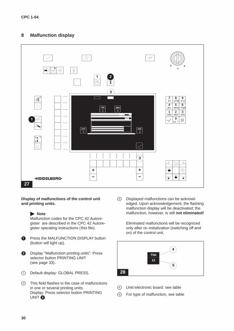
Display of malfunctions of the control unitand printing units.
� NoteMalfunction codes for the CPC 42 Autore-gister are described in the CPC 42 Autore-gister operating instructions (this file).
� Press the MALFUNCTION DISPLAY button(button will light up).
� Display ”Malfunction printing units”: Pressselector button PRINTING UNIT (see page 33).
� Default display: GLOBAL PRESS.
� This field flashes in the case of malfunctionsin one or several printing units.Display: Press selector button PRINTINGUNIT �.
� Displayed malfunctions can be acknowl-edged. Upon acknowledgement, the flashingmalfunction display will be deactivated; themalfunction, however, is still not eliminated!
Eliminated malfunctions will be recognizedonly after re–initialization (switching off andon) of the control unit.
28
1
TSK
12
TSK
� Unit /electronic board: see table
� For type of malfunction, see table

CPC 1-04
31
Malfunctiondisplay
Explanation Elimination of malfunction
All units
1 Malfunction in electroniccommunication
– Switch on CPTronic.
Inform HEIDELBERG service agent.
TSK driver/interface board1
TSK
1 Malfunction in electroniccommunication
Inform HEIDELBERG service agent.
10 Internal malfunction – Switch unit off and then on again.
11 ––> Inform HEIDELBERG service agent.
12 Hardware initialization malfunction Switch unit off and then on again.
13 Motor initialization malfunction Switch unit off and then on again.
BEK control unit board1
BEK
1 Malfunction in electroniccommunication
Inform HEIDELBERG service agent.
40 Value of manipulated variable does notfall within valid range
41
51 Malfunctiony reading of an internal job Repeat procedure
52 Malfunctiony writing of an internal job Repeat procedure
53 Malfunction in deletion of an internaljob
Repeat procedure
54 Job already in use Repeat command and ensure that the job isfree
55 Malfunction in release of a job Repeat procedure
61 Malfunctiony reading of an internalcharacteristic curve
Repeat procedure
62 Malfunctiony writing of an internal cha-racteristic curve
Repeat procedure
63 Malfunction in deletion of an internalcharacteristic curve
Repeat procedure
64 One of the selected characteristiccurves is already in use
Repeat command and ensure that allcharacteristic curves are free
65 Malfunction in release of acharacteristic curve
Repeat procedure
CPC 1-04
32
Malfunctiondisplay
Explanation Elimination of malfunction
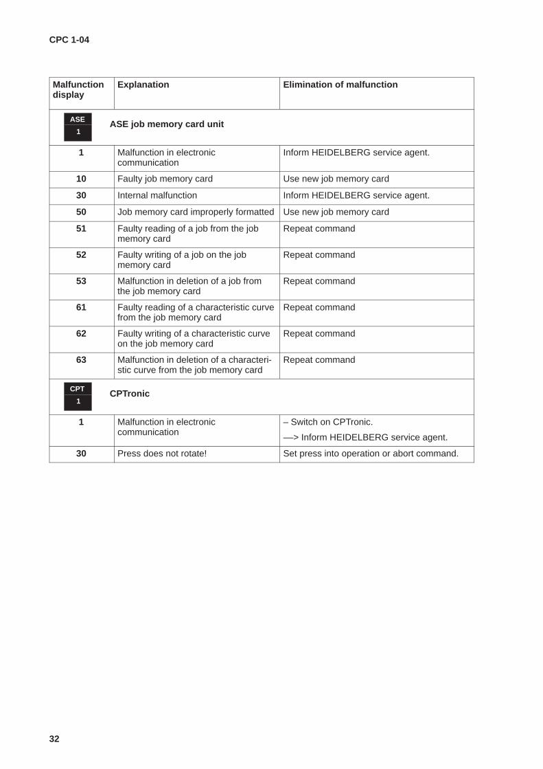
ASE job memory card unit1
ASE
1 Malfunction in electroniccommunication
Inform HEIDELBERG service agent.
10 Faulty job memory card Use new job memory card
30 Internal malfunction Inform HEIDELBERG service agent.
50 Job memory card improperly formatted Use new job memory card
51 Faulty reading of a job from the jobmemory card
Repeat command
52 Faulty writing of a job on the jobmemory card
Repeat command
53 Malfunction in deletion of a job fromthe job memory card
Repeat command
61 Faulty reading of a characteristic curvefrom the job memory card
Repeat command
62 Faulty writing of a characteristic curveon the job memory card
Repeat command
63 Malfunction in deletion of a characteri-stic curve from the job memory card
Repeat command
CPTronic1
CPT
1 Malfunction in electroniccommunication
– Switch on CPTronic.
––> Inform HEIDELBERG service agent.
30 Press does not rotate! Set press into operation or abort command.
CPC 1-04
33
29
01
2
1 2 3
4 5 6
7 8 9
0ABC DEF GHI
JKL MNO PQR
ST UVW XYZ
. /
SR
1
FD
3
3
FZxx
1
3
3
UR
DR
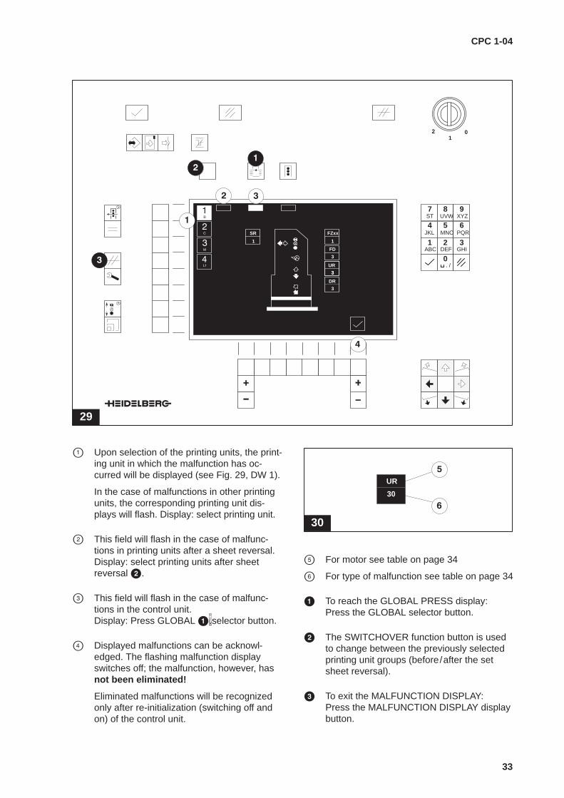
� Upon selection of the printing units, the print-ing unit in which the malfunction has oc-curred will be displayed (see Fig. 29, DW 1).
In the case of malfunctions in other printingunits, the corresponding printing unit dis-plays will flash. Display: select printing unit.
� This field will flash in the case of malfunc-tions in printing units after a sheet reversal.Display: select printing units after sheetreversal �.
� This field will flash in the case of malfunc-tions in the control unit.Display: Press GLOBAL ��selector button.
� Displayed malfunctions can be acknowl-edged. The flashing malfunction displayswitches off; the malfunction, however, hasnot been eliminated!
Eliminated malfunctions will be recognizedonly after re-initialization (switching off andon) of the control unit.
30
1
TSK
30
UR
� For motor see table on page 34
� For type of malfunction see table on page 34
� To reach the GLOBAL PRESS display:Press the GLOBAL selector button.
� The SWITCHOVER function button is usedto change between the previously selectedprinting unit groups (before/after the setsheet reversal).
� To exit the MALFUNCTION DISPLAY:Press the MALFUNCTION DISPLAY displaybutton.

CPC 1-04
34
Malfunctiondisplay
Explanation Elimination of malfunction
30
SRLateral register motor
31
FZ24Ink zone motor 24
30
FDInk fountain roller motor
30
URCircumferential register motor
31
DRDiagonal register motor
30 Motor does not rotate – check the cable
– motor may be sluggish
––> inform HEIDELBERG service agent.
31 Motor vibrates setting procedure is aborted.
CPC 1-04
35
9 Service display
9.1 SERVICE DISPLAY main menu
31
01
2
1 2 3
4 5 6
7 8 9
0ABC DEF GHI
JKL MNO PQR
ST UVW XYZ
. /
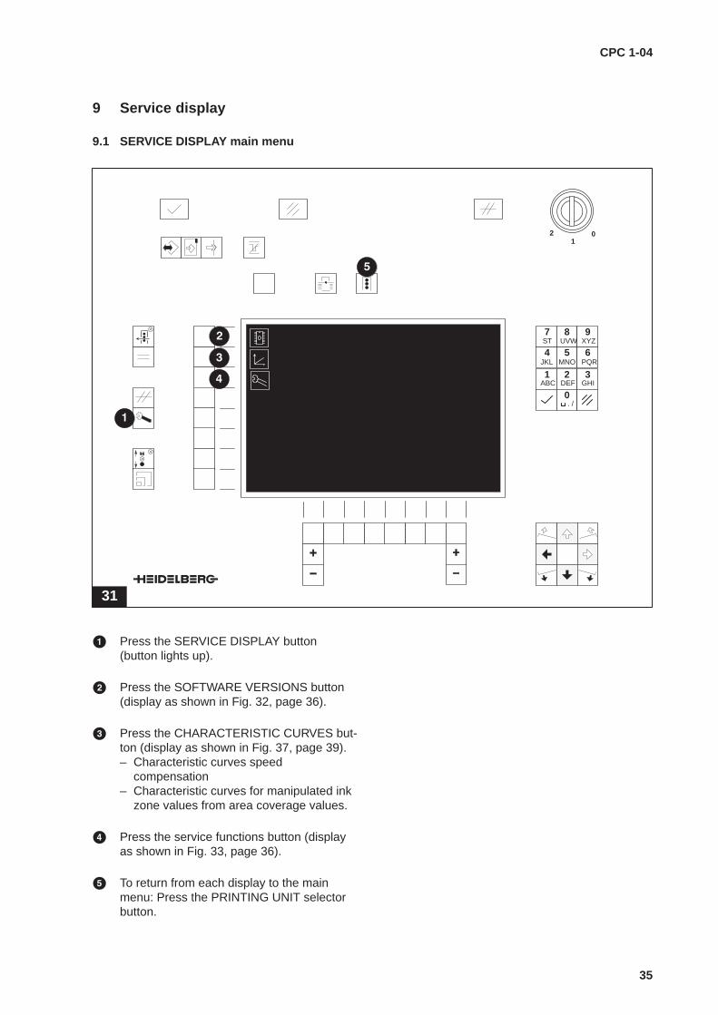
� Press the SERVICE DISPLAY button(button lights up).
� Press the SOFTWARE VERSIONS button(display as shown in Fig. 32, page 36).
� Press the CHARACTERISTIC CURVES but-ton (display as shown in Fig. 37, page 39).– Characteristic curves speed
compensation– Characteristic curves for manipulated ink
zone values from area coverage values.
� Press the service functions button (displayas shown in Fig. 33, page 36).
� To return from each display to the mainmenu: Press the PRINTING UNIT selectorbutton.

CPC 1-04
36
9.2 Software versions
Press the Software Versions � button (see Fig. 31, page 35).
32
CPT 20.0
TSK 1.1
ASE 3.5
EAM 4.0
C1D 103.0
BEK 103.0
The software versions of the electronic boardsused in the CPC 1-04 control console and thesoftware version of the connected CPTronic willbe shown (Fig.32 standard display, expansionpossible).
The abbreviations used stand for the following:
� CPT: CPTronic
� TSK: Driver/interface board
� ASE: Job memory card unit
� EAM: Input/output module
� C1D: Display software
� BEK: Control unit board
� NoteThese operating instructions for the CPC 1-04 (HDM no. 00.999.1922) are validfrom the CPC103.0 software package.This package currently consists of the soft-ware for the TSK1.1, C1D103.0 andBEK103.0 electronic boards.
9.3 Service functions
Press the Service Functions � button (see Fig. 31, page 35).
33
ZID
� NoteThe individual buttons and signal lamps inthe service functions � to � are to betested manually, i.e. by hand. Between pres-sing the button and activation of the displayof the buttons or signal lamps, there may bea delay.
� Upon pressing the button, the function andthe correct wiring of the luminous push but-tons will be checked.
� Upon pressing the button, the function andthe correct wiring of the signal lamps will bechecked.
� Upon pressing the button, the function andthe correct wiring of the feelers for the set-ting of the ink fountain zones will bechecked.
� Upon pressing the button, the function of theZID control console display will be checked.
CPC 1-04
37
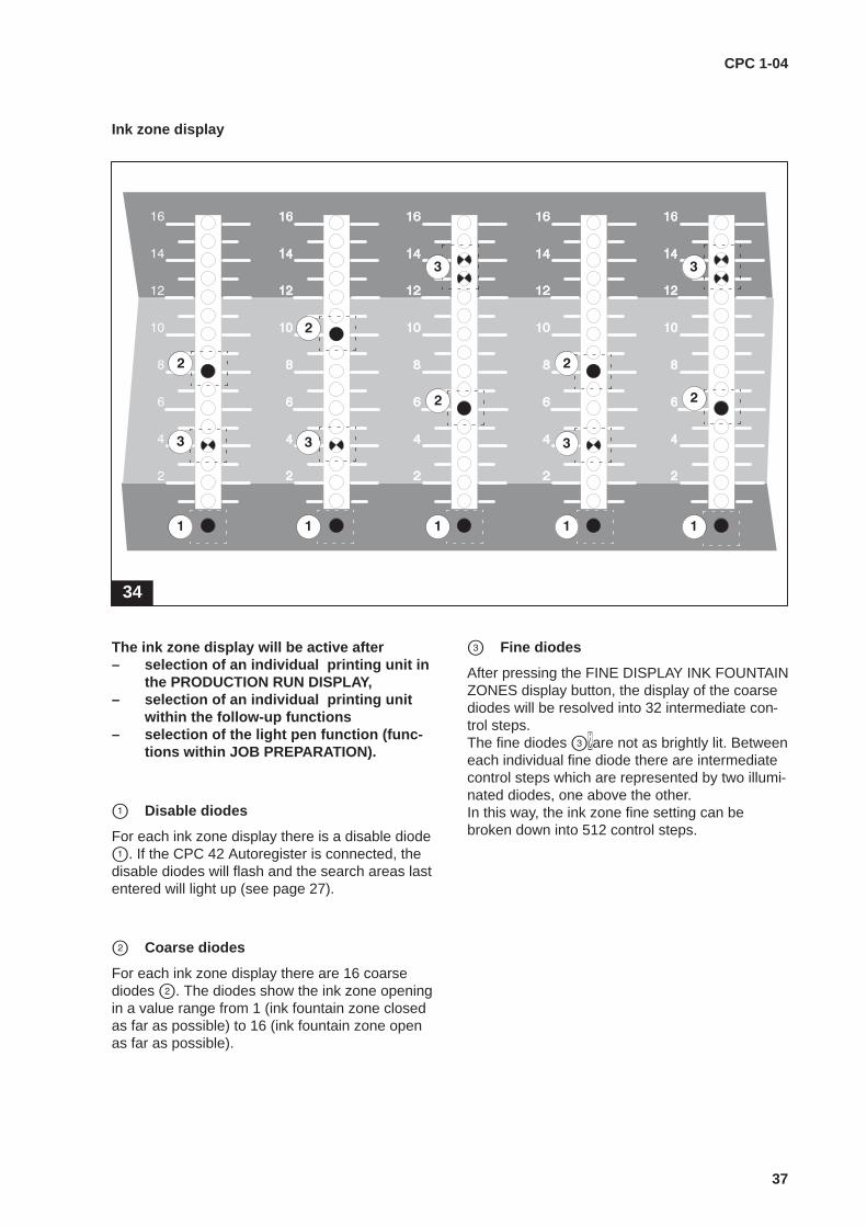
Ink zone display
34
The ink zone display will be active after– selection of an individual printing unit in
the PRODUCTION RUN DISPLAY,– selection of an individual printing unit
within the follow-up functions– selection of the light pen function (func-
tions within JOB PREPARATION).
� Disable diodes
For each ink zone display there is a disable diode�. If the CPC 42 Autoregister is connected, thedisable diodes will flash and the search areas lastentered will light up (see page 27).
� Coarse diodes
For each ink zone display there are 16 coarsediodes �. The diodes show the ink zone openingin a value range from 1 (ink fountain zone closedas far as possible) to 16 (ink fountain zone openas far as possible).
� Fine diodes
After pressing the FINE DISPLAY INK FOUNTAINZONES display button, the display of the coarsediodes will be resolved into 32 intermediate con-trol steps.The fine diodes ��are not as brightly lit. Betweeneach individual fine diode there are intermediatecontrol steps which are represented by two illumi-nated diodes, one above the other.In this way, the ink zone fine setting can bebroken down into 512 control steps.
CPC 1-04
38
10 Characteristic curves
10.1 Types of characteristic curves
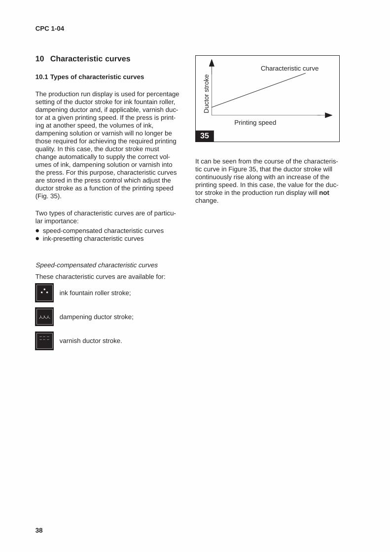
The production run display is used for percentagesetting of the ductor stroke for ink fountain roller,dampening ductor and, if applicable, varnish duc-tor at a given printing speed. If the press is print-ing at another speed, the volumes of ink,dampening solution or varnish will no longer bethose required for achieving the required printingquality. In this case, the ductor stroke mustchange automatically to supply the correct vol-umes of ink, dampening solution or varnish intothe press. For this purpose, characteristic curvesare stored in the press control which adjust theductor stroke as a function of the printing speed(Fig. 35).
Two types of characteristic curves are of particu-lar importance:
� speed-compensated characteristic curves� ink-presetting characteristic curves
Speed-compensated characteristic curves
These characteristic curves are available for:
ink fountain roller stroke;
dampening ductor stroke;
varnish ductor stroke.
35
2
Printing speed
Characteristic curve
Duc
tor
stro
ke
It can be seen from the course of the characteris-tic curve in Figure 35, that the ductor stroke willcontinuously rise along with an increase of theprinting speed. In this case, the value for the duc-tor stroke in the production run display will notchange.
CPC 1-04
39
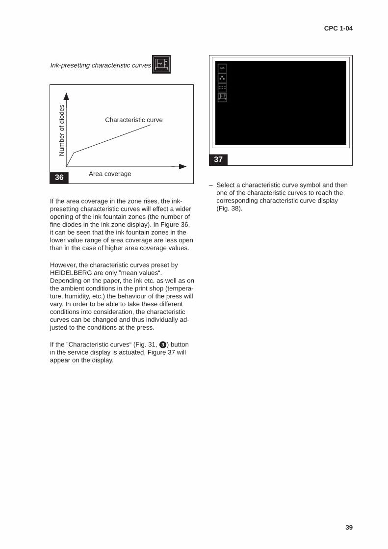
Ink-presetting characteristic curves
36 Area coverage
Characteristic curve
Num
ber
of d
iode
s
If the area coverage in the zone rises, the ink-presetting characteristic curves will effect a wideropening of the ink fountain zones (the number offine diodes in the ink zone display). In Figure 36,it can be seen that the ink fountain zones in thelower value range of area coverage are less openthan in the case of higher area coverage values.
However, the characteristic curves preset byHEIDELBERG are only ”mean values“.Depending on the paper, the ink etc. as well as onthe ambient conditions in the print shop (tempera-ture, humidity, etc.) the behaviour of the press willvary. In order to be able to take these differentconditions into consideration, the characteristiccurves can be changed and thus individually ad-justed to the conditions at the press.
If the ”Characteristic curves“ (Fig. 31, �) buttonin the service display is actuated, Figure 37 willappear on the display.
37
ZID
– Select a characteristic curve symbol and thenone of the characteristic curves to reach thecorresponding characteristic curve display (Fig. 38).

CPC 1-04
40
10.2 Change characteristic curves
38
100
%
10
0
3000 6000 15000 1/h
33
Z1(30)
Z2(70)
9000
10
20
40
50
60
80
9001
Figure 38 shows the characteristic curves for theink fountain roller stroke of the Speedmaster 102.
The characteristic curves display is called fromthe SERVICE DISPLAY main menu (button se-quence Fig. 39).
39
The numbers � and � highlighted white on thehorizontal and the vertical axes show the currentposition of the cursor (white cross, Fig. 38, �) inthe display window.
Example in Figure 38:
�: 9000 = printing speed 9000 i.p.h.
�: 33 = ink fountain roller stroke at 33%
� Display ink fountain roller stroke.Here, the vertical axis shows the ink fountainroller stroke from 0 to 100%. In the case ofthe SM 74 and the SM 52, the speed of theink fountain roller motor (1/min) is displayed(see also page 45).
� Cursor position ink fountain roller stroke.Indicates the ink fountain roller stroke at theposition of the cursor.
� Theoretical reference curve of the character-istic curves at 6000 i.p.h. (not displayed).
� HDM characteristic curve Z2 (70) Ink fountain roller value at 6000 i.p.h.: 70%.

CPC 1-04
41
� Possible characteristic curves for speedcompensation (not displayed).
� HDM characteristic curve Z1 (30) Ink fountain roller value at 6000 i.p.h.: 30%.
� Cursor position printing speed.Displays the printing speed at the position ofthe cursor.
� Printing speed display.The horizontal axis shows the printing speedbetween 3000 and 15000 impressions perhour (i.p.h.).
� Left-hand side +/– buttons on the controlconsole below the display (not visible in Fig. 38):– Selection of printing speed support posi-
tions (after selection of or ��).– Setting of percentage change (after selec-
tion of �).
Selection of support positions (for changingthe ink fountain roller stroke and the printingspeed, as button �).
� Abortion of entry; the display will return tothe next lower level.
� Percentage shifting of both characteristiccurves upward or downward (speed com-pensation stronger/weaker).
� Switchover between the HDM characteristiccurves Z1 and Z2.
� Selection of the support positions (for chang-ing the ink fountain roller stroke and theprinting speed, as button ).
Resetting of the characteristic curves to theinitial HDM characteristic curves.
� Confirmation of input
Right-hand side +/– buttons on the controlconsole below the display (not visible in Fig. 38)– Setting of the ink fountain roller stroke
support positions (after selection of , �or �).
CPC 1-04
42
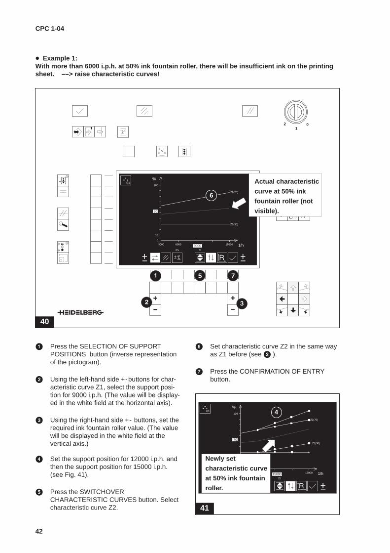
� Example 1:With more than 6000 i.p.h. at 50% ink fountain roller, there will be insufficient ink on the printingsheet. ––> raise characteristic curves!
40
01
2
1 2 3
4 5 6
7 8 9
0
ABC DEF GHI
JKL MNO PQR
ST UVW XYZ
. /
100
%
10
0
3000 6000 15000 1/h
30
Z1(30)
Z2(70)
9000
Actual characteristic
curve at 50% ink
fountain roller (not
visible).
5 7
01
� Press the SELECTION OF SUPPORTPOSITIONS button (inverse representationof the pictogram).
� Using the left-hand side +-buttons for char-acteristic curve Z1, select the support posi-tion for 9000 i.p.h. (The value will be display-ed in the white field at the horizontal axis).
� Using the right-hand side +- buttons, set therequired ink fountain roller value. (The valuewill be displayed in the white field at thevertical axis.)
� Set the support position for 12000 i.p.h. andthen the support position for 15000 i.p.h.(see Fig. 41).
� Press the SWITCHOVERCHARACTERISTIC CURVES button. Selectcharacteristic curve Z2.
� Set characteristic curve Z2 in the same wayas Z1 before (see � ).
� Press the CONFIRMATION OF ENTRYbutton.
41
100
%
10
0
3000 6000 15000 1/h
70Z1(30)
15000
Z2(70)
Newly set
characteristic curve
at 50% ink fountain
roller.
01
CPC 1-04
43
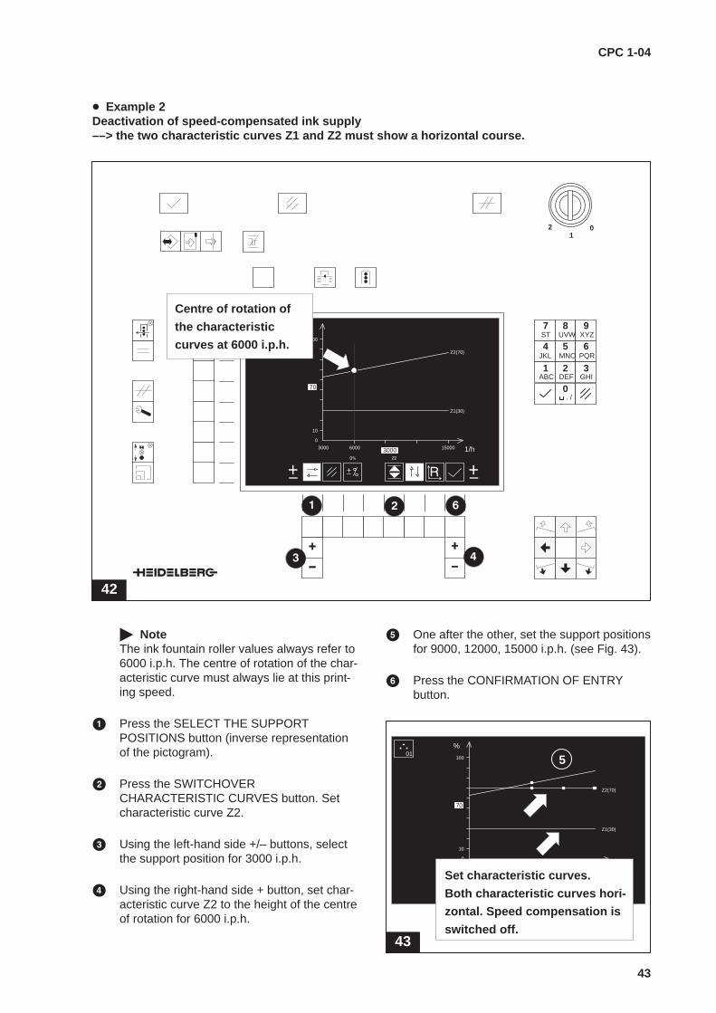
� Example 2Deactivation of speed-compensated ink supply––> the two characteristic curves Z1 and Z2 must show a horizontal course.
42
01
2
1 2 3
4 5 6
7 8 9
0ABC DEF GHI
JKL MNO PQR
ST UVW XYZ
. /
100
%
10
0
3000 6000 15000 1/h
70
Z1(30)
Z2(70)
3000
Centre of rotation of
the characteristic
curves at 6000 i.p.h.
� NoteThe ink fountain roller values always refer to6000 i.p.h. The centre of rotation of the char-acteristic curve must always lie at this print-ing speed.
� Press the SELECT THE SUPPORTPOSITIONS button (inverse representationof the pictogram).
� Press the SWITCHOVERCHARACTERISTIC CURVES button. Setcharacteristic curve Z2.
� Using the left-hand side +/– buttons, selectthe support position for 3000 i.p.h.
� Using the right-hand side + button, set char-acteristic curve Z2 to the height of the centreof rotation for 6000 i.p.h.
� One after the other, set the support positionsfor 9000, 12000, 15000 i.p.h. (see Fig. 43).
� Press the CONFIRMATION OF ENTRYbutton.
43
100
%
10
0
3000 6000 15000 1/h
70
Z1(30)
Z2(70)
12000
Set characteristic curves.
Both characteristic curves hori-
zontal. Speed compensation is
switched off.
015
CPC 1-04
44
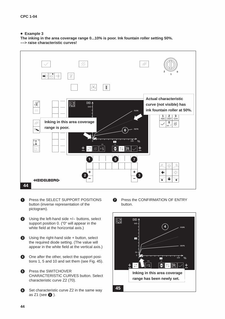
� Example 3The inking in the area coverage range 0...10% is poor. Ink fountain roller setting 50%.––> raise characteristic curves!
44
01
2
1 2 3
4 5 6
7 8 9
0ABC DEF GHI
JKL MNO PQR
ST UVW XYZ
. /
640
DIO
64
00 100 %
14
Z2(70)
Z1(30)
90000
Inking in this area coverage
range is poor.
ÍÍÍÍ
Actual characteristic
curve (not visible) has
ink fountain roller at 50%.BLA
75
� Press the SELECT SUPPORT POSITIONSbutton (inverse representation of thepictogram).
� Using the left-hand side +/– buttons, selectsupport position 0. (”0“ will appear in thewhite field at the horizontal axis.)
� Using the right-hand side + button, selectthe required diode setting. (The value willappear in the white field at the vertical axis.)
� One after the other, select the support posi-tions 1, 5 and 10 and set them (see Fig. 45).
� Press the SWITCHOVERCHARACTERISTIC CURVES button. Selectcharacteristic curve Z2 (70).
� Set characteristic curve Z2 in the same wayas Z1 (see � ).
� Press the CONFIRMATION OF ENTRYbutton.
640
DIO
64
00 100 %
14
Z2(70)
Z1(30)
0
45
Inking in this area coverage
range has been newly set.
ÍÍÍÍ
BLA

CPC 1-04
45
10.3 Speed-compensated characteristiccurves
Display
The speed-compensated characteristic curvesare used to control the stroke of ink fountainroller, dampening and varnish ductor. Dependingon the type of press, ink fountain rollers and duc-tors move differently:
SM 102Ink fountain roller: movement by stepsDampening, varnish ductor: continuous move-ment
SM 74, SM 52All ink fountain rollers and ductors: continuousmovement
In the case of stepwise movement, the stroke ofink fountain roller and ductors is shown in percentat the vertical axis (Fig. 46, �)
100
%
10
03000 6000 15000 1/h
30
Z1(30)
Z2(70)
9000
10
20
40
60
80
90
characteristic curves
(not visible)
46
In the case of continuous movement, the unit forthe stroke of ink fountain roller and ductors is thespeed of the ductor motor in 1/min and is shownat the vertical axis (Fig. 47, �).
47
3000
500
03000 6000 15000 1/h
850
Z1(30)
Z2(70)
9000
10
20
40
60
80
90
1/mininvisible
characteristic curves
Each ductor stroke (percentage or speed) re-quires its own characteristic curve. Since all ofthese characteristic curves closely resemble oneanother, only two of them will be shown in thedisplay:
Ink fountain roller andvarnish ductor: 30% and 70% (Fig. 47, �, �)
Dampening ductor: 20% and 60%
All other characteristic curves are available in thepress, but not visible on the display.
By using the two characteristic curves shown, thecourse of all other characteristic curves can bedetermined. As shown in Figure 47, the course ofthe characteristic curve ��is horizontal and be-comes steeper as the ductor stroke increases.The characteristic curve for 50% ink fountainroller/ductor stroke thus has a ”mean“ rise whichlies between the stroke at 30% and 70% (Fig. 47, �).
The interdependence between the characteristiccurves applies to all types and shapes of char-acteristic curve (e.g. Fig. 48 and 49).
48
100
%
10
03000 6000 15000 1/h
30
Z1(30)
9000
Z2(70)
49
3000
500
03000 6000 15000 1/h
2040Z1(30)
Z2(70)
9000
1/min
CPC 1-04
46
Change characteristic curves
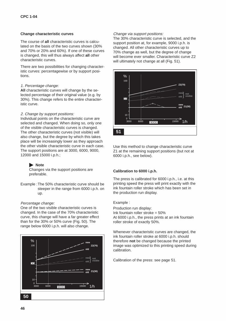
The course of all characteristic curves is calcu-lated on the basis of the two curves shown (30%and 70% or 20% and 60%). If one of these curvesis changed, this will thus always affect all othercharacteristic curves.
There are two possibilities for changing character-istic curves: percentagewise or by support posi-tions.
1. Percentage change:All characteristic curves will change by the se-lected percentage of their original value (e.g. by30%). This change refers to the entire character-istic curve.
2. Change by support positions:Individual points on the characteristic curve areselected and changed. When doing so, only oneof the visible characteristic curves is changed.The other characteristic curves (not visible) willalso change, but the degree by which this takesplace will be increasingly lower as they approachthe other visible characteristic curve in each case.The support positions are at 3000, 6000, 9000,12000 and 15000 i.p.h.;
� NoteChanges via the support positions arepreferable.
Example :The 50% characteristic curve should besteeper in the range from 6000 i.p.h. onup.
Percentage change:One of the two visible characteristic curves ischanged. In the case of the 70% characteristiccurve, this change will have a far greater effectthan for the 30% or 50% curve (Fig. 50). Therange below 6000 i.p.h. will also change.
50
100
%
10
03000 6000 15000 1/h
30
Z1(30)
Z2(70)
9000
old
new
old
old
new
new
notvisible
Change via support positions:The 30% characteristic curve is selected, and thesupport position at, for example, 9000 i.p.h. ischanged. All other characteristic curves up to70% change as well, but the degree of changewill become ever smaller. Characteristic curve Z2will ultimately not change at all (Fig. 51).
51
100
%
10
03000 6000 15000 1/h
33
Z1(30)
Z2(70)
9000
old
old
new
new
notvisible
Use this method to change characteristic curveZ1 at the remaining support positions (but not at6000 i.p.h., see below).
Calibration to 6000 i.p.h.
The press is calibrated for 6000 i.p.h., i.e. at thisprinting speed the press will print exactly with theink fountain roller stroke which has been set inthe production run display.
Example :
Production run display: Ink fountain roller stroke = 50%At 6000 i.p.h., the press prints at an ink fountainroller stroke of exactly 50%.
Whenever characteristic curves are changed, theink fountain roller stroke at 6000 i.p.h. shouldtherefore not be changed because the printedimage was optimized to this printing speed duringcalibration.
Calibration of the press: see page 51.

CPC 1-04
47
10.4 Characteristic curves for manipulated inkzone variables from area coverage values
52
640
DIO
64
00 100 %
14
Z2(70)
Z1(30)
9000
90
80
60
50
40
0
10
20
notvisible
Characteristic curves for the calculation of manip-ulated ink zone variables from the zonal area cov-erage values at a given ink fountain roller stroke.Here, a steeper characteristic curve will cause anincrease in the ink volume by opening the inkfountain zones in the ink fountain.
Horizontal axis: Area coverage Unit: % (Fig. 52, �)
Vertical axis: Ink fountain zone opening Unit: half fine diodes (Fig. 52, �)
Basically the same rules apply to a change ofcharacteristic curves as explained for speed-com-pensated characteristic curves. Differences existin the following:
� Support positions:Selection of the support positions at an areacoverage of 1, 5, 10, 20, 40, 70 and 100%.
� Visible characteristic curves:The characteristic curve Z2(70%) lies belowcharacteristic curve Z1 (30%) because the inkfountain zone opening at an ink fountain rollerstroke at 70% must be smaller than that at 30%.
Change of characteristic curves
If characteristic curves are changed for ink pres-etting, the following should be observed:
In the range of an area coverage between 0 and1%, the characteristic curves must not risesteeply; otherwise, the ink volume transferred atlow area coverage values will be too large(Fig. 53).
53
5
DIO
00 10 %
14
Z2(70)
9000
0
wrong
1 5
1
2
More favourable is a flat rise between 0% and1%, followed by a steeper one up to 5%. In thisway, the correct ink volume will be transferredalso to areas of low area coverage (Fig. 54). Thisis why the factory settings at the 0% and 1% sup-port positions should be maintained and nochanges made before the 5% support position.
54
5
DIO
00 10 %
14
Z2(70)
9000
0
correct
1 5
1
2

CPC 1-04
48
10.5 Store/ load characteristic curves
55
01
2
1 2 3
4 5 6
7 8 9
0ABC DEF GHI
JKL MNO PQR
ST UVW XYZ
. /
Characteristic curves can be stored on the jobmemory card. Three variants are possible:
� storing of the complete set of characteristiccurves, i.e. all types of characteristic curve;
� storing of one specific type of characteristiccurve (e.g. only the characteristic curves forarea coverage);
� storing of the characteristic ink curve for a spe-cific colour (e.g. characteristic curve for thearea coverage of the colour cyan).
A maximum of 1 complete set of characteristiccurves can be stored on one memory card. Differ-ent variants of one type of characteristic curve,however, cannot be stored. If a characteristiccurve (a type/set of characteristic curves) ischanged and then stored, the corresponding oldcharacteristic curve (the old type/set of character-istic curves) on the memory card will be over-written (see schematic representation in Fig. 56).
56
1 set of characteristic curves
Ink fountain Dampening
ductorVarnishductor
Ink pre–setting
10 8 6 7� � � �
roller

CPC 1-04
49
� Call up the ”Data transfer“ menu(Fig. 55, �).
� Press the ”Scroll“ (Fig. 55, �) button.Figure 57 will appear on the ZID central con-sole display.
57
Source selection
� The characteristic curves are written fromthe press memory onto the job memorycard.
� The characteristic curves are loaded fromthe job memory card into the press memory.
Characteristic curve selection
A total of 7 types of characteristic curve are avail-able for selection:
– 8 dampening ductor characteristic curves– 10 ink fountain roller characteristic curves– 6 varnish ductor characteristic curves– 7 ink presetting characteristic curves
– characteristic curve for ”Dead beat“– characteristic curve for CPC 2 follow-up– characteristic curve for preinking
� NoteThe characteristic curves for ”Dead beat“,CPC 2 follow-up and preinking cannot bechanged by the user.
The following variants are available for storingcharacteristic curves:
� storing of the complete set of characteristiccurves;
� storing of one specific type of characteristiccurve;
� storing of only one characteristic curve of aspecific type
Selection of type of characteristic curve:
Press the left-hand side +/– (Fig. 55, �) buttons.
Selection of individual characteristic curves:
Press the ”Fine display“ (Fig. 55, �) button; thenselect the desired characteristic curve, using theleft-hand side +/– buttons (Fig. 55, �).
If, for example, the characteristic curve for the inkfountain roller has been selected as type of char-acteristic curve, one of the following three sym-bols will appear at the position of Figure 57, �:
All internal characteristiccurves are selected.
All characteristic curves for the inkfountain roller stroke are selected.
Characteristic curve no. 5 for theink fountain roller stroke is selected.
� NoteIf the memory card is empty, nocharacteristic curve symbol will appear atthe position of Figure 57, �, and the+/– buttons will have no function.
CPC 1-04
50
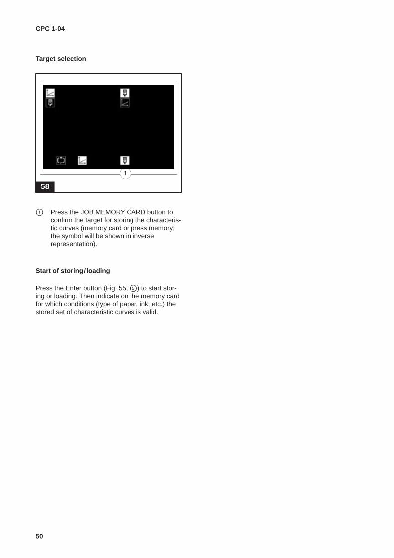
Target selection
58
� Press the JOB MEMORY CARD button toconfirm the target for storing the characteris-tic curves (memory card or press memory;the symbol will be shown in inverserepresentation).
Start of storing/ loading
Press the Enter button (Fig. 55, �) to start stor-ing or loading. Then indicate on the memory cardfor which conditions (type of paper, ink, etc.) thestored set of characteristic curves is valid.

CPC 1-04
51
10.6 Calibration of press
Due to the fact that the printing press is calibratedto 6000 i.p.h. (see page 48), it must be ensuredthat the characteristic curves at 6000 i.p.h. for theink fountain roller and ink presetting are really setto the optimum value.
Calibration of characteristic curve Z1 (30%):
� In the ”Job preparation“ menu, determine thecharacteristic curves used by the press toprint the current job (see page 74).
� In the production run display, set the inkfountain roller stroke to 30% (or 20%) andprint at 6000 i.p.h.
� Using the ink zone keys below the ink zonedisplay, change the setting of the ink foun-tain zones until the optimum printing resulthas been achieved.
� Print at 3000 i.p.h. The printed image willshow some underinking.
� Call up the characteristic curve display andthe characteristic curve determined in step � . Select the support position for3000 i.p.h. on the characteristic curveZ1(30% or 20%).
� Change the characteristic curve using theright-hand side +/– buttons, press ”OK“ toconfirm and wait until the result has becomevisible in the printed image (while doing so,watch the inking unit’s reaction. The changein the printed image will become visible onlyafter a certain period of time). If necessary,correct the characteristic curve again.
� One after the other, select the support posi-tions for 9000, 12000 and 15000 i.p.h. andchange the characteristic curve so that anoptimum printed image is reached at anyprinting speed.
Calibration of characteristic curve Z2 (70%):
� In the ”Job preparation“ menu, determine thecharacteristic curves used by the press toprint the current job (unless already done forcharacteristic curve Z1, see page 74).
� In the production run display, set the inkfountain roller stroke to 70% (or 60%) andprint at 6000 i.p.h.
� Using the ink zone keys below the ink zonedisplay, change the setting of the ink foun-tain zones until an optimum printing resulthas been achieved.
� Print at 3000 i.p.h. The printed image willshow some underinking.
� Call up the characteristic curve display andthe characteristic curve determined in step � . Select the support position for3000 i.p.h. on the characteristic curve Z2(70% or 60%).
Proceed as described for characteristic curve Z1.
� Store the characteristic curve or the com-plete set of characteristic curves (see page 48).
Checking of characteristic curves
To check characteristic curves, set the ink foun-tain roller stroke at 50%. The printing result mustbe of consistent quality within a printing speedrange between 3000 i.p.h. and 15000 i.p.h., with-out requiring changes in the ink fountain zones orthe ink fountain roller stroke.

CPC 1-04
52
Master copy
Characteristic curve designation:Characteristic curve no.:
Ink fountain roller,support position X,
Actual value (% for SM 102, 1/min for SM 74 and SM 52)support position X,printing speed (1/h) Z1 Z2
3000
6000
9000
12000
15000
Characteristic curve designation:Characteristic curve no.:
Dampening ductor,support position X,
Actual value (% for SM 102, 1/min for SM 74 and SM 52)support position X,printing speed (1/h) Z1 Z2
3000
6000
9000
12000
15000
Characteristic curve designation:Characteristic curve no.:
Varnish ductor,support position X,
Actual value (% for SM 102, 1/min for SM 74 and SM 52)support position X,printing speed (1/h) Z1 Z2
3000
6000
9000
12000
15000
CPC 1-04
53
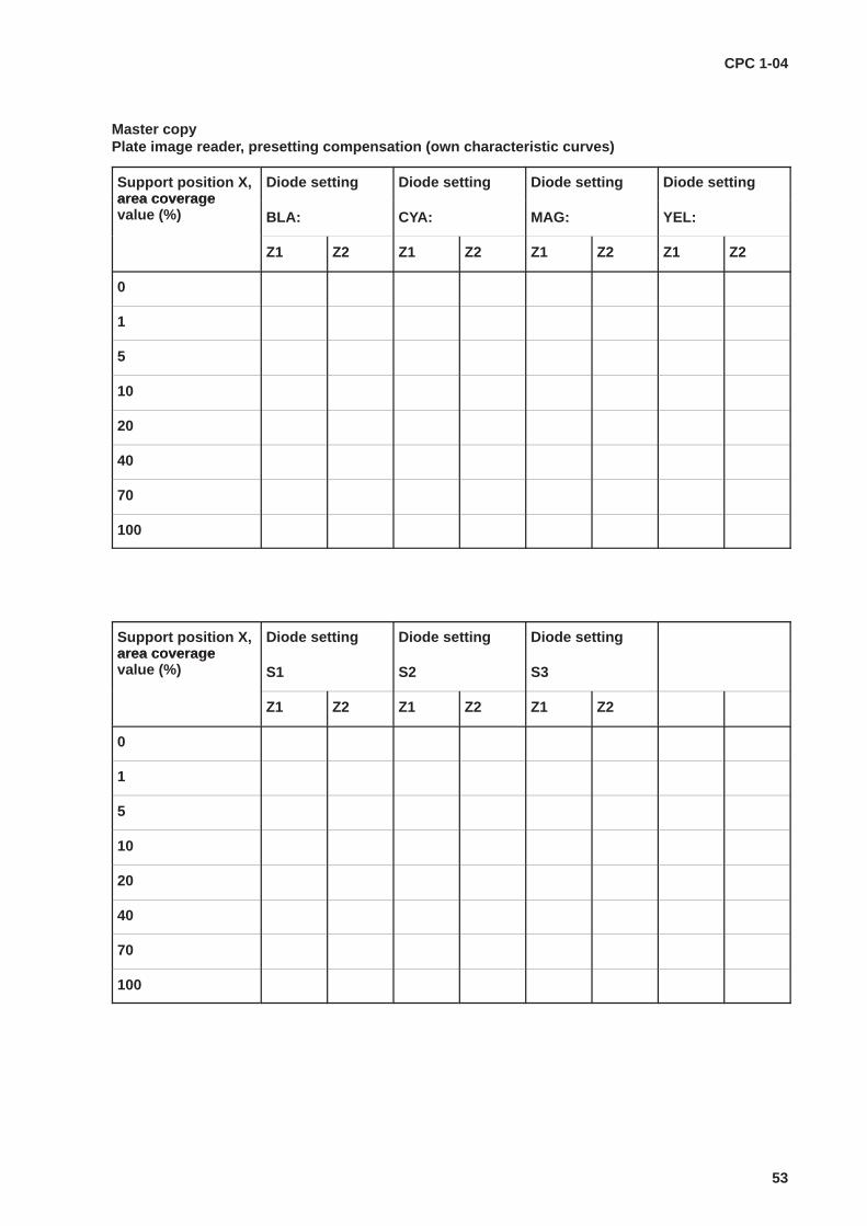
Master copyPlate image reader, presetting compensation (own characteristic curves)
Support position X,area coverage
Diode setting Diode setting Diode setting Diode settingarea coveragevalue (%) BLA: CYA: MAG: YEL:
Z1 Z2 Z1 Z2 Z1 Z2 Z1 Z2
0
1
5
10
20
40
70
100
Support position X,area coverage
Diode setting Diode setting Diode settingarea coveragevalue (%) S1 S2 S3
Z1 Z2 Z1 Z2 Z1 Z2
0
1
5
10
20
40
70
100
CPC 1-04
54
11 Data transfer
11.1 Overview
59
01
2
1 2 3
4 5 6
7 8 9
0ABC DEF GHI
JKL MNO PQR
ST UVW XYZ
. /
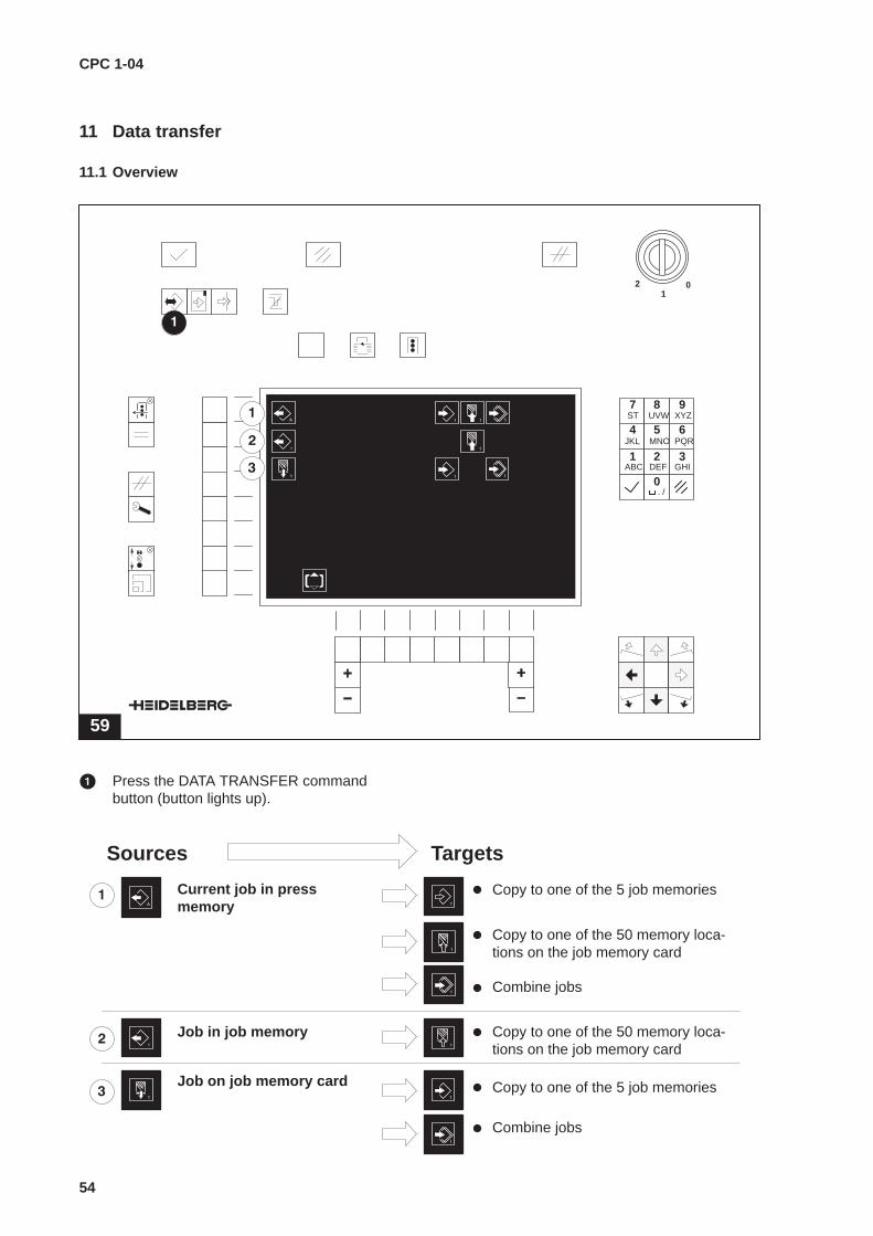
� Press the DATA TRANSFER commandbutton (button lights up).
Job in job memory
Job on job memory card
Copy to one of the 5 job memories
Copy to one of the 50 memory loca-tions on the job memory card
Combine jobs
Copy to one of the 50 memory loca-tions on the job memory card
Copy to one of the 5 job memories
Combine jobs
Current job in pressmemory
Sources Targets

CPC 1-04
55
� Current job in press memory (see page 58)
� Copy to one of the 5 job memories.
Current job in pressmemory
Copy to one of the 5 jobmemories
� Copy to one of the 50 memory locations on thejob memory card.
Current job in pressmemory
Copy to one of the 50 memorylocations on the job memorycard
� Combine jobs.
Current job in pressmemory
Combine jobs
Job data (colours) can be combined with a jobalready stored at one of the 5 internal memorylocations.
Explanation ref. ”Combine jobs“
If the colours for source and target are ident-ical, the colour values of the source will beadopted.
Example 1:A stored two-colour job is changed to a four-colour job. Additional colours are adopted andcolours already stored are retained.
Source Target Result
Black 1 Magenta 2 Black 1
Cyan 1 Yellow 2 Cyan 1
Magenta 2
Yellow 2
Black 1 Magenta 2 Black 1
Magenta 1 Yellow 2 Magenta 1
Yellow 2
Example 2:In a stored four-colour job (B, C, M, Y), the set-tings for the colours magenta and yellow are to beoverwritten. Store new settings for magenta andyellow; black and cyan are retained.
Source Target Result
Magenta 1 Black 2 Black 2
Yellow 1 Cyan 2 Cyan 2
Magenta 2 Magenta 1
Yellow 2 Yellow 1

CPC 1-04
56
� Job in job memory (see page 60)
� Copy to one of the 50 memory locations on thejob memory card.
Job in job memory
Copy to one of the 50 memorylocations on the job memorycard

CPC 1-04
57
� Job on job memory card (see page 62)
� Copy to one of the 5 job memories.
Job on job memory card
Copy to one of the 5 jobmemories
� Combine jobs.
Job on job memory card
Combine jobs
Job data (colours) can be stored in addition to ajob already stored at one of the 5 internal memorylocations.
If the colours for source and target are ident-ical, the colour values of the source will beadopted.
Example 1:A stored two-colour job is changed to a four-co-lour job. Additional colours are accepted and co-lours already stored are retained.
Source Target Result
Black 1 Magenta 2 Black 1
Cyan 1 Yellow 2 Cyan 1
Magenta 2
Yellow 2
Black 1 Magenta 2 Black 1
Magenta 1 Yellow 2 Magenta 1
Yellow 2
Example 2:In a stored four-colour job (B, C, M, Y), the set-tings for the colours magenta and yellow are to beoverwritten. Store new settings for magenta andyellow; black and cyan are retained.
Source Target Result
Magenta 1 Black 2 Black 2
Yellow 1 Cyan 2 Cyan 2
Magenta 2 Magenta 1
Yellow 2 Yellow 1
Displays for repeat jobs
60
300965
– – – – –– – – – –
� Job exists, job name defined.
� Job exists, no job name defined.
� NoteSee also page 64
� No job available.
CPC 1-04
58
11.2 Current job in press memory
61
01
2
300965
1 2 3
4 5 6
7 8 9
0ABC DEF GHI
JKL MNO PQR
ST UVW XYZ
. /
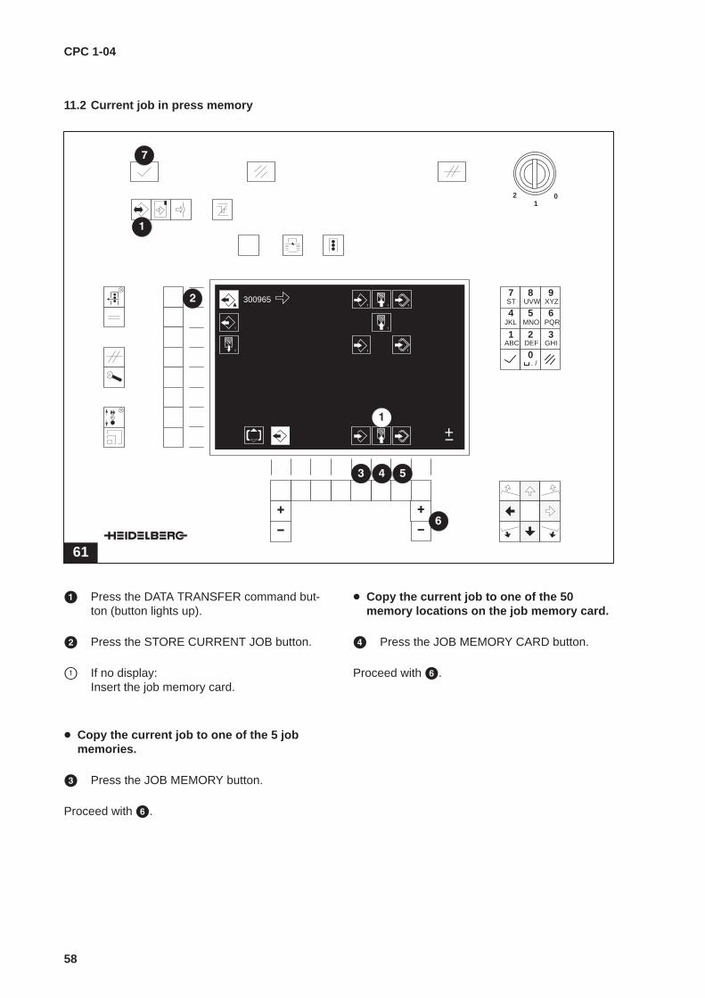
� Press the DATA TRANSFER command but-ton (button lights up).
� Press the STORE CURRENT JOB button.
� If no display: Insert the job memory card.
� Copy the current job to one of the 5 jobmemories.
� Press the JOB MEMORY button.
Proceed with �.
� Copy the current job to one of the 50memory locations on the job memory card.
� Press the JOB MEMORY CARD button.
Proceed with �.

CPC 1-04
59
� Combine current job with stored job in thejob memory.
� Press the COMBINE JOBS button.
Proceed with �.
� Using the right-hand side +/– buttons, definethe respective memory location (job memory1...5, job memory card 1...50).
� Enable the command by pressing theENTER button.
Caution – danger of data loss if thejob memory card is removedprematurely
During reading or writing on the job memorycard, the red signal lamp will light up. Do notremove the card as long as the lamp is lit:data loss!Remove the card only after the ENTER but-ton has switched off or the display haschanged.

CPC 1-04
60
11.3 Job in job memory
62
01
2
300965
1 2 3
4 5 6
7 8 9
0ABC DEF GHI
JKL MNO PQR
ST UVW XYZ
. /
� Copy job in the job memory to one of the 50memory locations on the job memory card.
� Press the DATA TRANSFER button (buttonlights up).
� Press the JOB MEMORY button.
� Using the left-hand side +/– buttons, selectthe job to be copied from the job memory(1...5).
� If no display: Insert the job memory card.
� DELETE JOB:Press function button � and enable com-mand by pressing the ENTER button.

CPC 1-04
61
� Press the JOB MEMORY CARD button.
� Using the right-hand side +/– buttons, definethe memory location on the job memory card(1...50).
� NoteIf there is already a repeat job in the definedmemory location, then this will be over-written. Various displays are possible for re-peat jobs (see Fig. 60, page 57).
� Enable command by pressing the ENTERbutton.
Caution – Danger of data loss if thejob memory card is removedprematurely
During reading or writing on the job memorycard, the red signal lamp will light up. Do notremove card as long as the lamp is lit: dataloss!Remove the card only after the ENTER but-ton has switched off or the display haschanged.
CPC 1-04
62
11.4 Job on job memory card,formatting of job memory card
63
01
2
300965
no card
new card
1 2 3
4 5 6
7 8 9
0ABC DEF GHI
JKL MNO PQR
ST UVW XYZ
. /
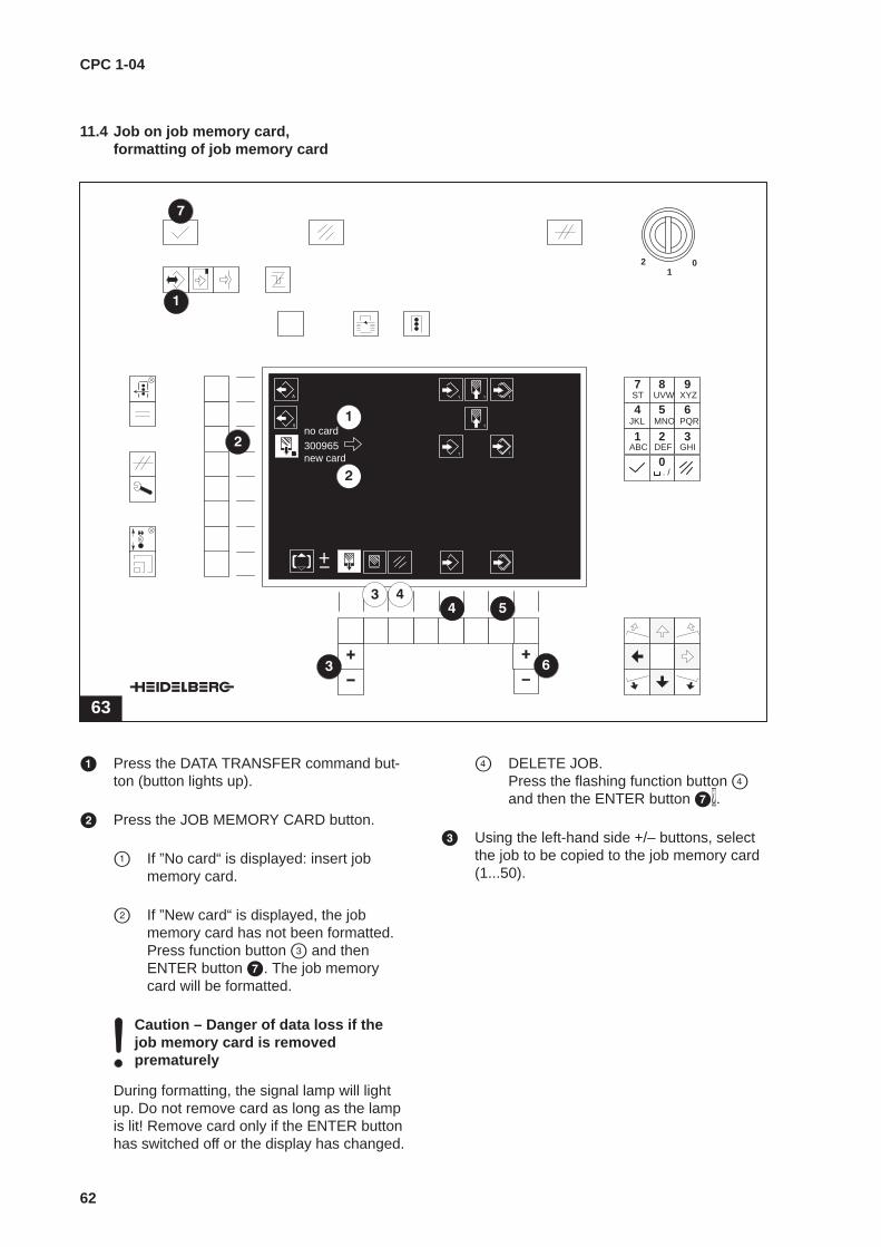
� Press the DATA TRANSFER command but-ton (button lights up).
� Press the JOB MEMORY CARD button.
� If ”No card“ is displayed: insert jobmemory card.
� If ”New card“ is displayed, the jobmemory card has not been formatted.Press function button � and thenENTER button �. The job memorycard will be formatted.
Caution – Danger of data loss if thejob memory card is removedprematurely
During formatting, the signal lamp will lightup. Do not remove card as long as the lampis lit! Remove card only if the ENTER buttonhas switched off or the display has changed.
� DELETE JOB.Press the flashing function button �and then the ENTER button ��.
� Using the left-hand side +/– buttons, selectthe job to be copied to the job memory card(1...50).
CPC 1-04
63
� Copy job to one of the 5 job memories.
� Press the JOB MEMORY button.
Proceed with �.
� Combine job with the stored job in the jobmemory.
� Press the COMBINE JOBS button.
� Using the right-hand side +/– buttons, definethe internal memory location (1...5).
� NoteIf there is already a repeat job in the definedmemory location, then this will be over-written. This is not the case with the com-bine jobs function.Various displays are possible for repeat jobs(see page 57, Fig. 60).
� Enable command by pressing the ENTERbutton.
Caution – Danger of data loss if thejob memory card is removedprematurely
When reading or writing on the job memorycard, the red signal lamp will light up. Do notremove card as long as the lamp is lit: dataloss!Remove card only after the ENTER buttonhas switched off or the display has changed.
CPC 1-04
64
12 Job preparation
12.1 Select memory location
64
01
2
4711
123456
987654
– – – – – – – – –– – – – – – – – –
– – – – – – – – –– – – – – – – – –
1 2 3
4 5 6
7 8 9
0ABC DEF GHI
JKL MNO PQR
ST UVW XYZ
. /
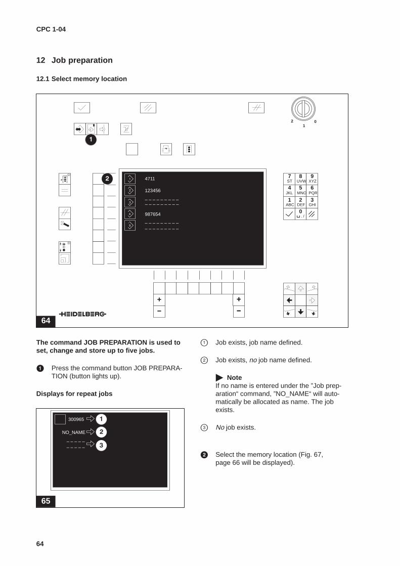
The command JOB PREPARATION is used toset, change and store up to five jobs.
� Press the command button JOB PREPARA-TION (button lights up).
Displays for repeat jobs
65
300965
– – – – –– – – – –
NO_NAME
� Job exists, job name defined.
� Job exists, no job name defined.
� NoteIf no name is entered under the ”Job prep-aration“ command, ”NO_NAME“ will auto-matically be allocated as name. The jobexists.
� No job exists.
� Select the memory location (Fig. 67,page 66 will be displayed).
CPC 1-04
65
12.2 Display selection menu GLOBAL PRESS
66
01
2
1 2 3
4 5 6
7 8 9
0ABC DEF GHI
JKL MNO PQR
ST UVW XYZ
. /
300965
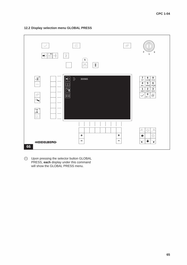
� Upon pressing the selector button GLOBALPRESS, each display under this commandwill show the GLOBAL PRESS menu.
CPC 1-04
66
12.3 Enter job name
67
01
2
300965
1 2 3
4 5 6
7 8 9
0ABC DEF GHI
JKL MNO PQR
ST UVW XYZ
. /
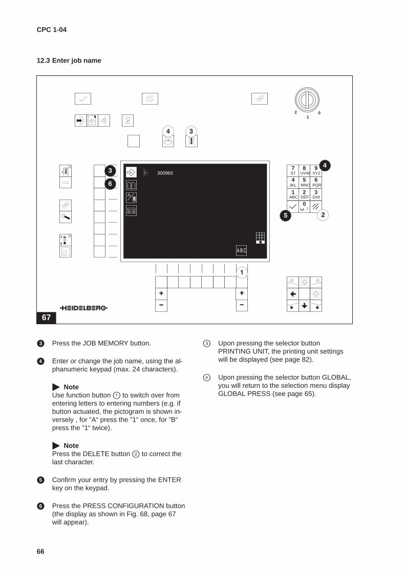
� Press the JOB MEMORY button.
� Enter or change the job name, using the al-phanumeric keypad (max. 24 characters).
� NoteUse function button � to switch over fromentering letters to entering numbers (e.g. ifbutton actuated, the pictogram is shown in-versely , for ”A“ press the ”1“ once, for ”B“press the ”1“ twice).
� NotePress the DELETE button � to correct thelast character.
� Confirm your entry by pressing the ENTERkey on the keypad.
� Press the PRESS CONFIGURATION button(the display as shown in Fig. 68, page 67 will appear).
� Upon pressing the selector buttonPRINTING UNIT, the printing unit settingswill be displayed (see page 82).
� Upon pressing the selector button GLOBAL,you will return to the selection menu displayGLOBAL PRESS (see page 65).
CPC 1-04
67
12.4 Sheet reversing device - switching on and off, change colour
Printing press with one sheet reversing device
68
01
2
300965
1 2 3
4 5 6
7 8 9
0ABC DEF GHI
JKL MNO PQR
ST UVW XYZ
. /
� NoteThe small symbols straight printing/perfect-ing are always displayed in front of theprinting unit with sheet reversing device(counting direction).
� Switch on the sheet reversing device.Inverse display of sheet reversing device;colour symbols in the printing units behindthe sheet reversing device flashing (initialstate, see Fig. 69).
� Upon pressing the selector buttonPRINTING UNIT, the printing unit settingswill be displayed (see page 82).
� Upon pressing the selector button GLOBAL,you will return to the selection menu displayGLOBAL PRESS (see page 65).
� For colour allocation, see page 71.
69
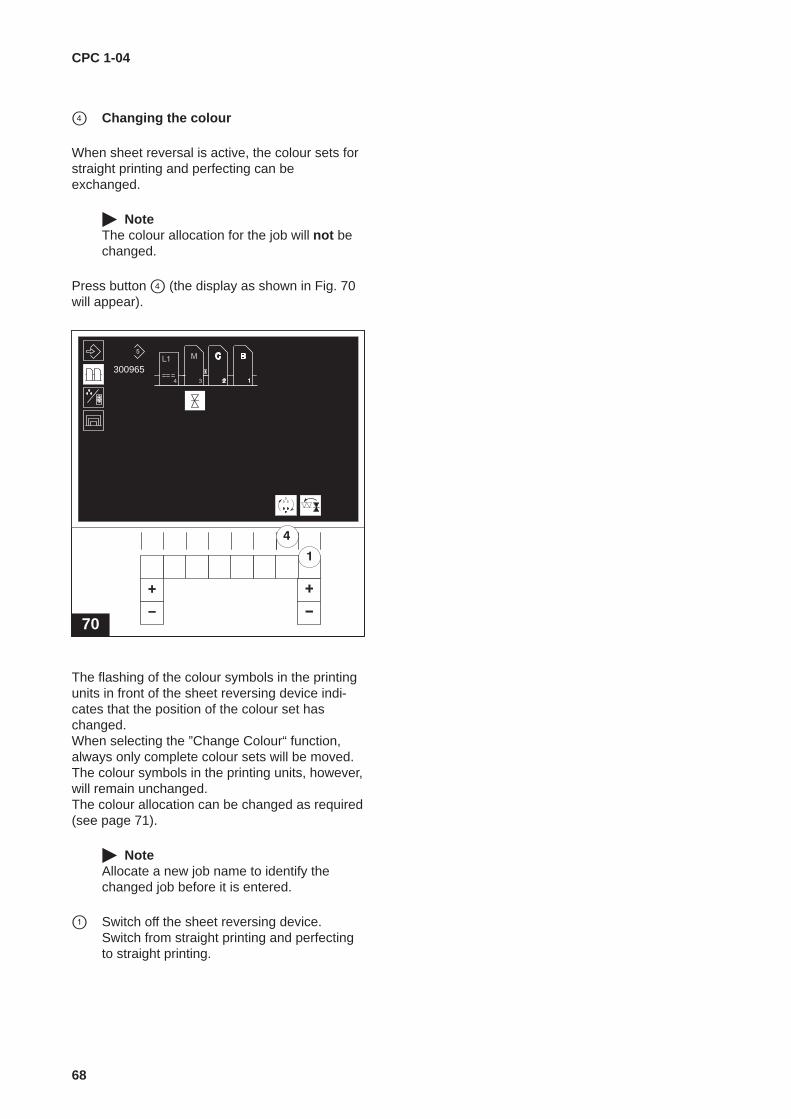
CPC 1-04
68
� Changing the colour
When sheet reversal is active, the colour sets forstraight printing and perfecting can beexchanged.
� NoteThe colour allocation for the job will not bechanged.
Press button � (the display as shown in Fig. 70will appear).
70
300965
The flashing of the colour symbols in the printingunits in front of the sheet reversing device indi-cates that the position of the colour set haschanged.When selecting the ”Change Colour“ function,always only complete colour sets will be moved.The colour symbols in the printing units, however,will remain unchanged.The colour allocation can be changed as required(see page 71).
� NoteAllocate a new job name to identify thechanged job before it is entered.
� Switch off the sheet reversing device. Switch from straight printing and perfectingto straight printing.
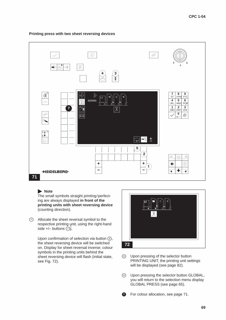
CPC 1-04
69
Printing press with two sheet reversing devices
71
01
2
300965
1 2 3
4 5 6
7 8 9
0ABC DEF GHI
JKL MNO PQR
ST UVW XYZ
. /
� NoteThe small symbols straight printing/perfect-ing are always displayed in front of theprinting units with sheet reversing device(counting direction).
� Allocate the sheet reversal symbol to therespective printing unit, using the right-handside +/– buttons ��.
Upon confirmation of selection via button �,the sheet reversing device will be switchedon. Display for sheet reversal inverse; coloursymbols in the printing units behind thesheet reversing device will flash (initial state,see Fig. 72).
72
� Upon pressing of the selector buttonPRINTING UNIT, the printing unit settingswill be displayed (see page 82).
� Upon pressing the selector button GLOBAL,you will return to the selection menu displayGLOBAL PRESS (see page 65).
� For colour allocation, see page 71.

CPC 1-04
70
� Changing the colour
When sheet reversal is active, the colour sets forstraight printing and perfecting can beexchanged.
� NoteThe colour allocation for the job will not bechanged.
Press the button � (the display as shown inFig. 73 will appear).
73
300965
The flashing of the colour symbols in the printingunits in front of the sheet reversing device indi-cates the change in position of the colour set.When selecting the function ”Change colour“, onlycomplete colour sets will be moved. The coloursymbols in the printing units, however, will remainunchanged.The colour allocation can be changed as required(see page 71).
� NoteAllocate a new job name to identify thechanged job before it is entered.
� Switch off the sheet reversing device. Switch from straight printing and perfectingto straight printing.
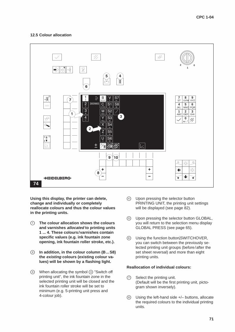
CPC 1-04
71
12.5 Colour allocation
74
01
2
300965
1 2 3
4 5 6
7 8 9
0ABC DEF GHI
JKL MNO PQR
ST UVW XYZ
. /
Using this display, the printer can delete,change and individually or completelyreallocate colours and thus the colour valuesin the printing units.
� The colour allocation shows the coloursand varnishes allocated to printing units1 ... 4. These colours �/�varnishes containspecific values (e.g. ink fountain zoneopening, ink fountain roller stroke, etc.).
� In addition, in the colour column (B...S8)the existing colours (existing colour va-lues) will be shown by a flashing light.
� When allocating the symbol � ”Switch offprinting unit“, the ink fountain zone in theselected printing unit will be closed and theink fountain roller stroke will be set tominimum (e.g. 5-printing unit press and4-colour job).
� Upon pressing the selector buttonPRINTING UNIT, the printing unit settingswill be displayed (see page 82).
� Upon pressing the selector button GLOBAL,you will return to the selection menu displayGLOBAL PRESS (see page 65).
� Using the function button�SWITCHOVER,you can switch between the previously se-lected printing unit groups (before/after theset sheet reversal) and more than eightprinting units.
Reallocation of individual colours:
� Select the printing unit.(Default will be the first printing unit, picto-gram shown inversely).
� Using the left-hand side +/– buttons, allocatethe required colours to the individual printingunits.

CPC 1-04
72
� Delete allocation of colours (colour va-lues) and varnishes to printing units:
� NoteVarnishes allocated to the coating units willalso be removed!
Press button � (the display as shown in Fig. 75will appear).
75
300965
Press the SELECTION CONFIRMATIONbutton � (the display as shown in Fig. 76 willappear).
76
300965
All allocated colours are removed from the print-ing units. Existing colours (colour values) willflash in the colour column.Now all colours (with and without colour values)can be allocated to the printing units:
– Select the printing unit.– Using the left-hand side +/– buttons, all-
cate the required colours to the individualprinting units.
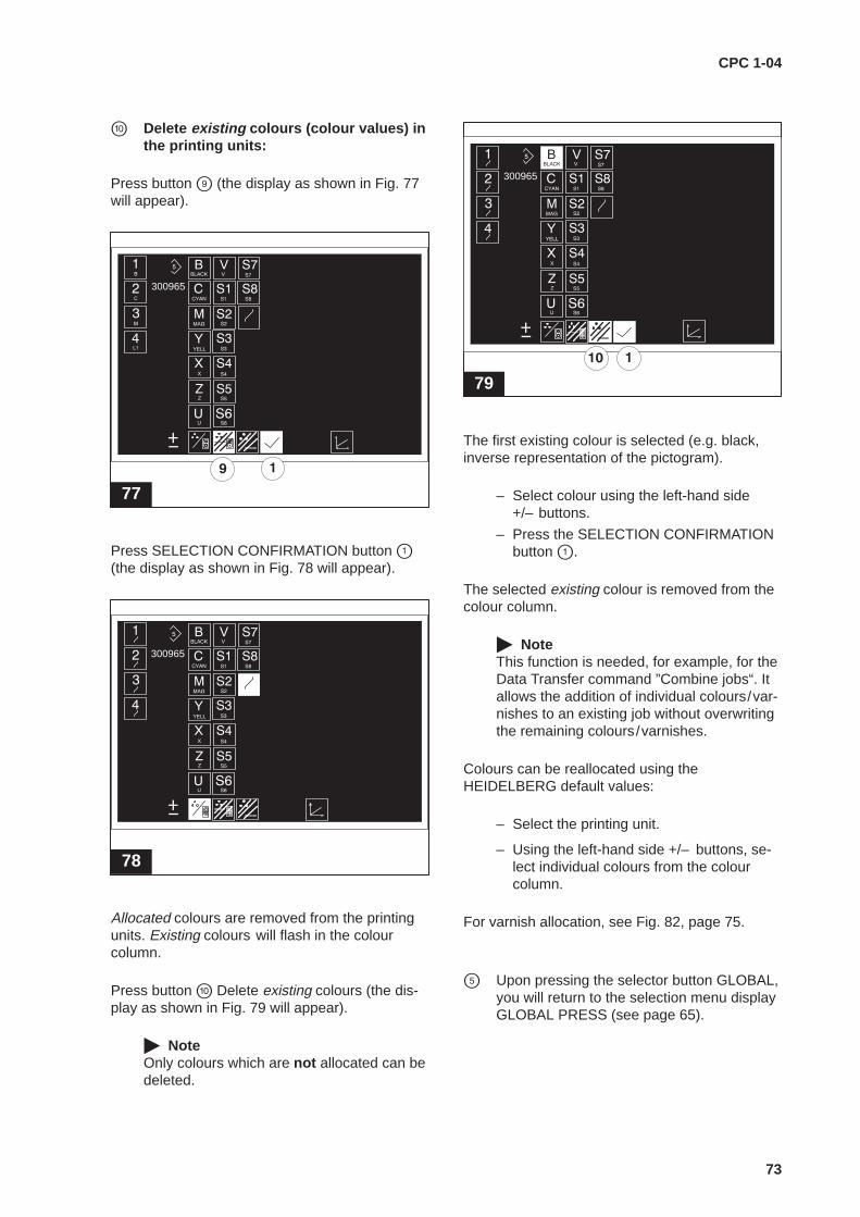
CPC 1-04
73
� Delete existing colours (colour values) inthe printing units:
Press button � (the display as shown in Fig. 77will appear).
77
300965
Press SELECTION CONFIRMATION button �(the display as shown in Fig. 78 will appear).
78
300965
Allocated colours are removed from the printingunits. Existing colours will flash in the colourcolumn.
Press button � Delete existing colours (the dis-play as shown in Fig. 79 will appear).
� NoteOnly colours which are not allocated can bedeleted.
79
300965
The first existing colour is selected (e.g. black,inverse representation of the pictogram).
– Select colour using the left-hand side+/– buttons.
– Press the SELECTION CONFIRMATIONbutton �.
The selected existing colour is removed from thecolour column.
� NoteThis function is needed, for example, for theData Transfer command ”Combine jobs“. Itallows the addition of individual colours/var-nishes to an existing job without overwritingthe remaining colours/varnishes.
Colours can be reallocated using theHEIDELBERG default values:
– Select the printing unit.
– Using the left-hand side +/– buttons, se-lect individual colours from the colourcolumn.
For varnish allocation, see Fig. 82, page 75.
� Upon pressing the selector button GLOBAL,you will return to the selection menu displayGLOBAL PRESS (see page 65).
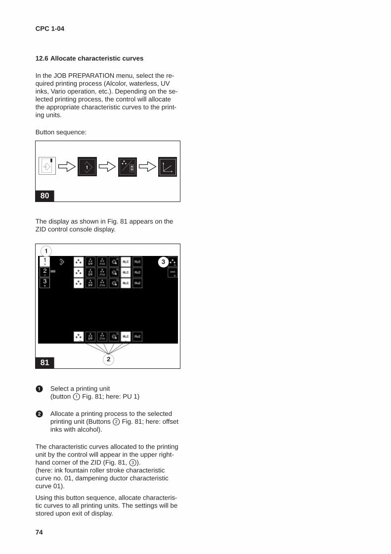
CPC 1-04
74
12.6 Allocate characteristic curves
In the JOB PREPARATION menu, select the re-quired printing process (Alcolor, waterless, UVinks, Vario operation, etc.). Depending on the se-lected printing process, the control will allocatethe appropriate characteristic curves to the print-ing units.
Button sequence:
80
The display as shown in Fig. 81 appears on theZID control console display.
81
� Select a printing unit (button � Fig. 81; here: PU 1)
� Allocate a printing process to the selectedprinting unit (Buttons � Fig. 81; here: offsetinks with alcohol).
The characteristic curves allocated to the printingunit by the control will appear in the upper right-hand corner of the ZID (Fig. 81, �).(here: ink fountain roller stroke characteristiccurve no. 01, dampening ductor characteristiccurve 01).
Using this button sequence, allocate characteris-tic curves to all printing units. The settings will bestored upon exit of display.
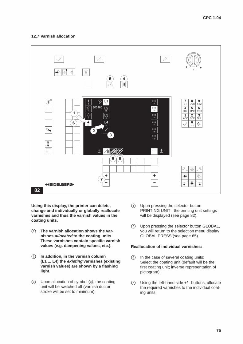
CPC 1-04
75
12.7 Varnish allocation
82
01
2
300965
1 2 3
4 5 6
7 8 9
0ABC DEF GHI
JKL MNO PQR
ST UVW XYZ
. /
01
02
03
04
05
06
Using this display, the printer can delete,change and individually or globally reallocatevarnishes and thus the varnish values in thecoating units.
� The varnish allocation shows the var-nishes allocated to the coating units.These varnishes contain specific varnishvalues (e.g. dampening values, etc.).
� In addition, in the varnish column (L1 ... L4) the existing varnishes (existingvarnish values) are shown by a flashinglight.
� Upon allocation of symbol �, the coatingunit will be switched off (varnish ductorstroke will be set to minimum).
� Upon pressing the selector buttonPRINTING UNIT , the printing unit settingswill be displayed (see page 82).
� Upon pressing the selector button GLOBAL,you will return to the selection menu displayGLOBAL PRESS (see page 65).
Reallocation of individual varnishes:
� In the case of several coating units:Select the coating unit (default will be thefirst coating unit; inverse representation ofpictogram).
� Using the left-hand side +/– buttons, allocatethe required varnishes to the individual coat-ing units.
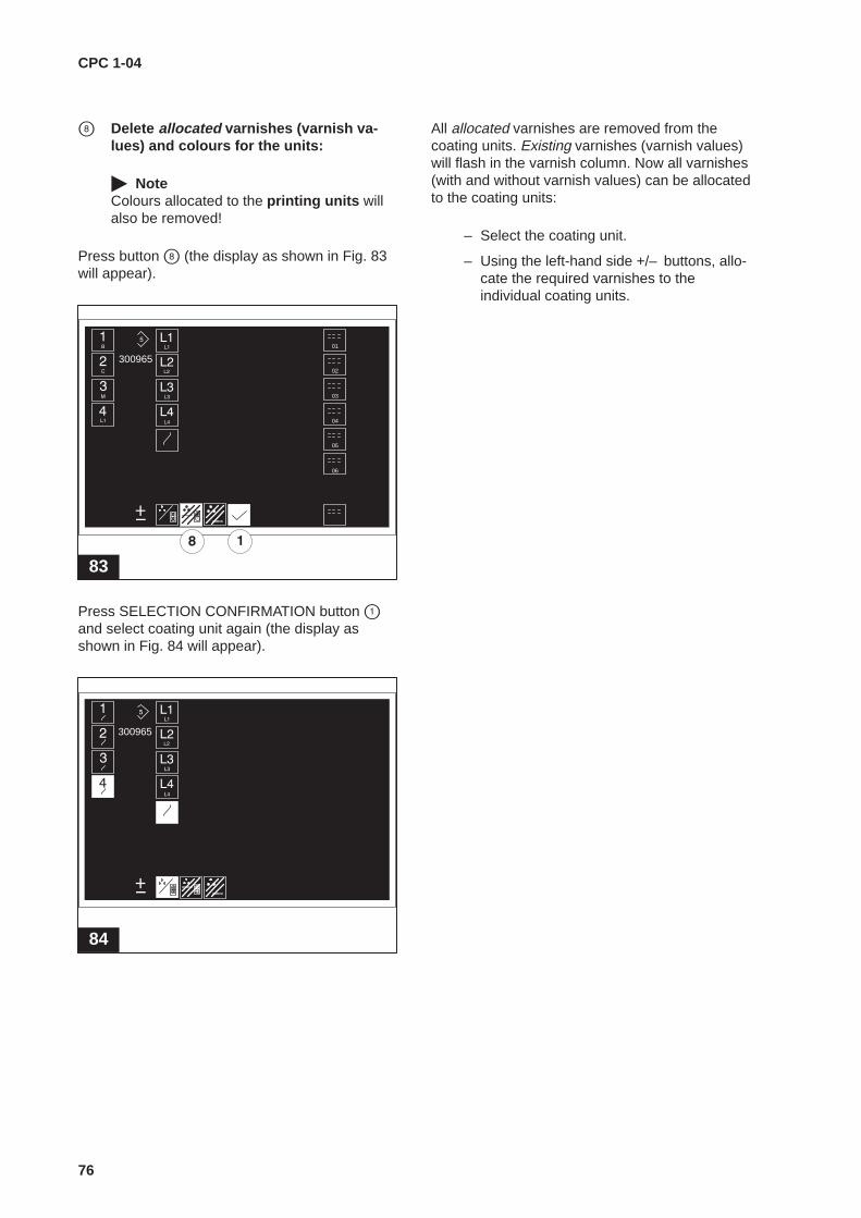
CPC 1-04
76
� Delete allocated varnishes (varnish va-lues) and colours for the units:
� NoteColours allocated to the printing units willalso be removed!
Press button � (the display as shown in Fig. 83will appear).
83
30096501
02
03
04
05
06
Press SELECTION CONFIRMATION button �and select coating unit again (the display asshown in Fig. 84 will appear).
84
300965
All allocated varnishes are removed from thecoating units. Existing varnishes (varnish values)will flash in the varnish column. Now all varnishes(with and without varnish values) can be allocatedto the coating units:
– Select the coating unit.
– Using the left-hand side +/– buttons, allo-cate the required varnishes to theindividual coating units.
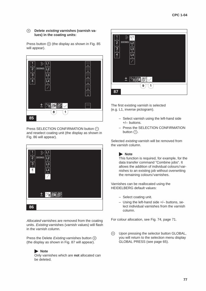
CPC 1-04
77
� Delete existing varnishes (varnish va-lues) in the coating units:
Press button � (the display as shown in Fig. 85will appear).
85
30096501
02
03
04
05
06
Press SELECTION CONFIRMATION button �and reselect coating unit (the display as shown inFig. 86 will appear).
86
300965
Allocated varnishes are removed from the coatingunits. Existing varnishes (varnish values) will flashin the varnish column.
Press the Delete Existing varnishes button �(the display as shown in Fig. 87 will appear).
� NoteOnly varnishes which are not allocated canbe deleted.
87
300965
The first existing varnish is selected(e.g. L1, inverse pictogram).
– Select varnish using the left-hand side +/– buttons.
– Press the SELECTION CONFIRMATIONbutton �.
Selected existing varnish will be removed fromthe varnish column.
� NoteThis function is required, for example, for thedata transfer command ”Combine jobs“. Itallows the addition of individual colours/var-nishes to an existing job without overwritingthe remaining colours/varnishes.
Varnishes can be reallocated using theHEIDELBERG default values:
– Select coating unit.
– Using the left-hand side +/– buttons, se-lect individual varnishes from the varnishcolumn.
For colour allocation, see Fig. 74, page 71.
� Upon pressing the selector button GLOBAL,you will return to the selection menu displayGLOBAL PRESS (see page 65).

CPC 1-04
78
12.8 Allocate characteristic curves forvarnishes
As in the case of printing units, different char-acteristic curves can also be allocated to thecoating unit.
Button sequence:
88
L14
In the ZID central console display, the display asshown in Fig. 89 will appear.
89
The coating unit symbol (Fig. 89, �) is shown ininverse representation.
� Using the right-hand side +/– buttons (Fig. 89, �), select a characteristic curve.
The symbol for the selected characteristic curvewill be shown inversely (Fig. 89, �).
� The setting will be stored upon exit ofdisplay.

CPC 1-04
79
12.9 Allocate characteristic curves from the plate image reader to a colour
90
01
2
300965
1 2 3
4 5 6
7 8 9
0ABC DEF GHI
JKL MNO PQR
ST UVW XYZ
. /
BLABLA
If area coverage values for a colour exist in ajob (job measured by the plate image reader),the characteristic curve symbols will appearin this display.
Different characteristic curves can beallocated to the colours.
To convert area coverage values (e.g. determinedusing the plate image reader) into manipulatedink zone values, to each colour B .... S8 one ofthe characteristic curves BLA .... S3 can be allo-cated. Using this allocated characteristic curve,the manipulated ink zone values will becalculated.Changes to the characteristic curves (see page 39 ff.) are taken into consideration in thiscalculation.
� Allocate characteristic curve to the selectedcolour
� Select printing unit /colour.
� Using the right-hand side +/– buttons, allo-cate characteristic curve.
� NoteAllocated characteristic curves will automati-cally be changed with change in colour.
� Upon pressing the selector button GLOBAL,you will return to the selection menu displayGLOBAL PRESS (see page 65).
� Upon pressing the selector buttonPRINTING UNIT , the printing unit settingswill be displayed (see page 82).
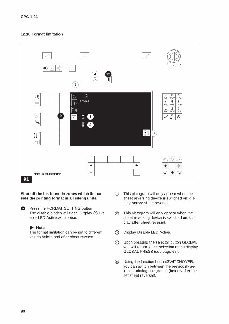
CPC 1-04
80
12.10 Format limitation
91
01
2
300965
1 2 3
4 5 6
7 8 9
0ABC DEF GHI
JKL MNO PQR
ST UVW XYZ
. /
Shut off the ink fountain zones which lie out-side the printing format in all inking units.
� Press the FORMAT SETTING button.The disable diodes will flash. Display � Dis-able LED Active will appear.
� NoteThe format limitation can be set to differentvalues before and after sheet reversal.
� This pictogram will only appear when thesheet reversing device is switched on: dis-play before sheet reversal.
� This pictogram will only appear when thesheet reversing device is switched on: dis-play after sheet reversal.
� Display Disable LED Active.
� Upon pressing the selector button GLOBAL,you will return to the selection menu displayGLOBAL PRESS (see page 65).
� Using the function button�SWITCHOVER,you can switch between the previously se-lected printing unit groups (before/after theset sheet reversal).

CPC 1-04
81
� Align the printing sheet centrally on the CPC 1-04 control unit (Fig. 92).
92
� On both sides, press the first minus ink zonebutton which lies outside the format (Fig. 92). The disable diodes of the disabled zones willlight up, the light-emitting diodes of thezones within the format will continue to flash.
� NoteDisabled zones can be opened up again byusing the Plus ink zone keys.
� Upon pressing the selector buttonPRINTING UNIT, the printing unit settingswill be displayed (see page 82).
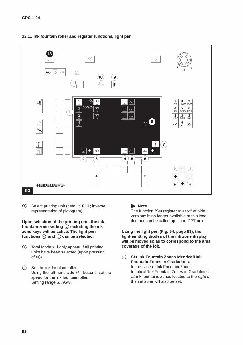
CPC 1-04
82
12.11 Ink fountain roller and register functions, light pen
93
02
300965
01
2
1 2 3
4 5 6
7 8 9
0ABC DEF GHI
JKL MNO PQR
ST UVW XYZ
. /
� Select printing unit (default: PU1; inverserepresentation of pictogram).
Upon selection of the printing unit, the inkfountain zone setting � including the inkzone keys will be active. The light penfunctions � and � can be selected.
� Total Mode will only appear if all printingunits have been selected (upon pressingof �).
� Set the ink fountain roller.Using the left-hand side +/– buttons, set thespeed for the ink fountain roller.Setting range 5...95%.
� NoteThe function ”Set register to zero“ of olderversions is no longer available at this loca-tion but can be called up in the CPTronic.
Using the light pen (Fig. 94, page 83), thelight-emitting diodes of the ink zone displaywill be moved so as to correspond to the areacoverage of the job.
� Set Ink Fountain Zones Identical / InkFountain Zones in Gradations.In the case of Ink Fountain ZonesIdentical / Ink Fountain Zones in Gradations,all ink fountains zones located to the right ofthe set zone will also be set.

CPC 1-04
83
94
29 30 31 32
� Random setting of ink fountain zones.In the case of random ink fountain zones,each zone must be separately set.
� Setting of the varnish ductor.Using the right-hand side +/– buttons, setthe speed for the varnish ductor.Setting range: 0...99%.
� The ink fountain zone setting display isactivated.
� Display of varnish values in coating unit.
� Upon pressing the selector button PRINT-ING UNIT, total mode � will be activated.
� Upon pressing the selector switch GLOBAL,you will return to the selection menu displayGLOBAL PRESS (see page 65).
� Using the function button�SWITCHOVER,you can switch between the previously se-lected printing unit groups (before/after theset sheet reversal).
� Enable command JOB PREPARATION bypressing the ENTER button.
� NoteValues which have been set will be stored inthe selected job memory.
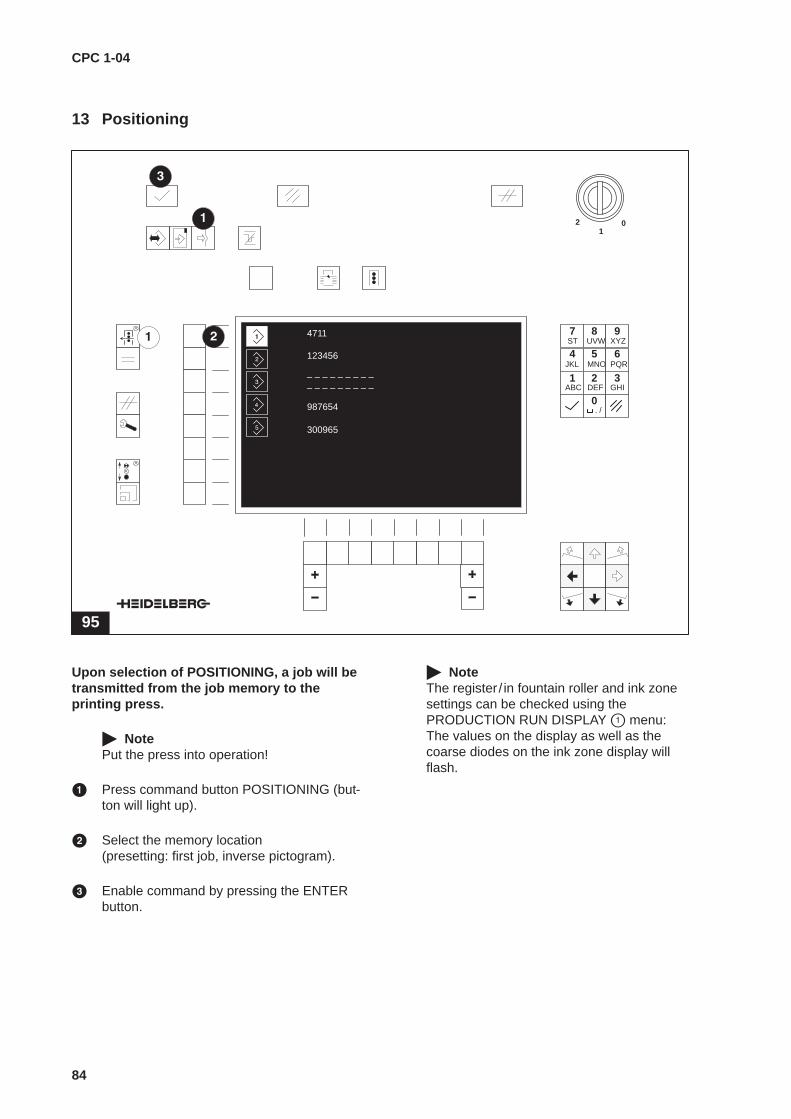
CPC 1-04
84
13 Positioning
95
01
2
4711
123456
987654
– – – – – – – – –– – – – – – – – –
300965
1 2 3
4 5 6
7 8 9
0ABC DEF GHI
JKL MNO PQR
ST UVW XYZ
. /
Upon selection of POSITIONING, a job will betransmitted from the job memory to theprinting press.
� NotePut the press into operation!
� Press command button POSITIONING (but-ton will light up).
� Select the memory location(presetting: first job, inverse pictogram).
� Enable command by pressing the ENTERbutton.
� NoteThe register / in fountain roller and ink zonesettings can be checked using thePRODUCTION RUN DISPLAY � menu:The values on the display as well as thecoarse diodes on the ink zone display willflash.
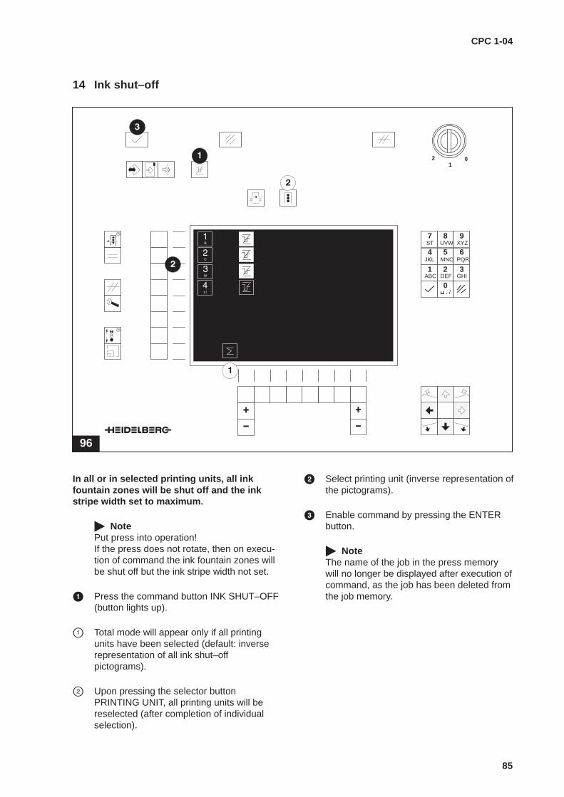
CPC 1-04
85
14 Ink shut–off
96
01
2
1 2 3
4 5 6
7 8 9
0ABC DEF GHI
JKL MNO PQR
ST UVW XYZ
. /
In all or in selected printing units, all inkfountain zones will be shut off and the inkstripe width set to maximum.
� NotePut press into operation!If the press does not rotate, then on execu-tion of command the ink fountain zones willbe shut off but the ink stripe width not set.
� Press the command button INK SHUT–OFF(button lights up).
� Total mode will appear only if all printingunits have been selected (default: inverserepresentation of all ink shut–offpictograms).
� Upon pressing the selector buttonPRINTING UNIT, all printing units will bereselected (after completion of individualselection).
� Select printing unit (inverse representation ofthe pictograms).
� Enable command by pressing the ENTERbutton.
� NoteThe name of the job in the press memorywill no longer be displayed after execution ofcommand, as the job has been deleted fromthe job memory.

CPC 1-04
86

CPC 1-04
87
Index
AAutomatic follow–up control 29Automatic register control 26
selection 25Autoregister 25, 26
BBASIC DISPLAY 25Buttons control panel 8
CCalibration of press 51Card formatting 62Changing the colour 68Characteristic curves 38
allocate 74, 78calibraton of press 51change 40from plate image reader allocate 79ink presetting- 39, 47raise 42speed–compensated 38, 45store/load 48-types 38
Characteristic curves for varnishes allocate 78Coarse diodes 37Colour allocation see JOB PREPARATION 71Colours
allocated 71delete allocated colours 72delete existing colours 73existing 71reallocate 71
Command abort command 18Commands
command correction and command interruption 18command execution 18command functions 17command initialization 17enable command 18general 17
Control consoles 7Control panel 6CPC 2 25, 28CPC 21 25, 28CPC 41 25, 26CPC 41 register control 26CPC 42 25, 26CPC 42 Autoregister 26
search areas 27Current job in press memory 58
D
Dampening values 23Dampening values/varnish values 23DATA TRANSFER 54
current job in press memory 58job in job memory 60Job on job memory card 62overview 54
Dead beat 29Disable diodes 37Displays in the display 9
E
Enter job name see JOB PREPARATION 66
F
FAULT DISPLAY 30Fine diodes 37FINE DISPLAY INK FOUNTAIN ZONES 37FINE DISPLAYS INK FOUNTAIN ZONES 22Follow–up control 29Follow–up functions 28
selection 25Format limitation see JOB PREPARATION 80Formatting 62Function overview 7
I
Ink fountain roller- and register functionssee JOB PREPARATION 82
Ink fountain roller presetting 82Ink fountain roller values 22Ink fountain zone setting 22Ink fountain zone setting percentage 22INK SHUT–OFF 85Ink zone display 37
J
Job in job memory 60Job memory card 19
formatting 62general 19inserting 19master copy contents 20
Job on job memory card 62

CPC 1-04
88
JJOB PREPARATION 64
Allocate characteristic curves from the plateimage reader 79change colour 67Colour allocation 71enter job name 66format limitation 80ink fountain roller- and register functions 82light pen 82Press with one sheet reversing device 67press with two sheet reversing devices 69select memory location 64sheet reversing device on/off 67varnish allocation 75
LLight pen see JOB PREPARATION 82
MMalfunctions at the control unit 30Master copy
characteristic curve for manipulated ink zone values 53contents job memory card 20speed–compensated characteristic curves 52
Measured data from CPC 2/CPC 21 28Memory card 19
NNoise emission values 3Not ready: printing units 30, 33
OOperator control overview
BASIC DISPLAY 16DATA TRANSFER 14JOB PREPARATION 15PRODUCTION RUN DISPLAY 16
PPercentage setting of ink fountain zones 22Pictograms in the display 9POSITIONING 84PRODUCTION RUN DISPLAY 22
QQuality control 28
R
Register display at zero 22Register reader 25, 26Register setting 23
S
Safety instructions 3Search areas CPC 42 Autoregister 27Select memory location
see JOB PREPARATION 64SERVICE DISPLAY 35Service functions 36Setting of registers 23Sheet reversing device on/off
one 67two 69
Software versions 36Speed–compensated characteristic curvesmaster copy 52Speed–compensated ink supply 35
deactivate 43Structure
complete unit 5control panel 6functions 7
Switching off 21Switching on 21Symbols in the display 9
T
Technical data 3Transporting the unit 4
V
Varnish allocation see JOB PREPARATION 75Varnish values 23Varnishes
allocated 71, 75delete allocated varnishes 76delete existing varnishes 77existing 75reallocate 75
W
Weight 4