control user guide - melcsa.com | inicio€¦ · control user guide unidrive m100/101 ... control...
TRANSCRIPT

Control User Guide
Unidrive M100/101
Variable Speed AC drive for induction motors
Part Number: 0478-0352-01Issue: 1

Original InstructionsFor the purposes of compliance with the EU Machinery Directive 2006/42/EC:
General informationThe manufacturer accepts no liability for any consequences resulting from inappropriate, negligent or incorrect installation or adjustment of the optional operating parameters of the equipment or from mismatching the variable speed drive with the motor.
The contents of this guide are believed to be correct at the time of printing. In the interests of a commitment to a policy of continuous development and improvement, the manufacturer reserves the right to change the specification of the product or its performance, or the contents of the guide, without notice.
All rights reserved. No part of this guide may be reproduced or transmitted in any form or by any means, electrical or mechanical including photocopying, recording or by an information storage or retrieval system, without permission in writing from the publisher.
Drive firmware versionThis product is supplied with the latest firmware version. If this drive is to be connected to an existing system or machine, all drive firmware versions should be verified to confirm the same functionality as drives of the same model already present. This may also apply to drives returned from an Emerson Industrial Automation Service Centre or Repair Centre. If there is any doubt please contact the supplier of the product.
The firmware version of the drive can be checked by looking at Pr 11.029 and Pr 11.035.
Environmental statementEmerson Industrial Automation is committed to minimising the environmental impacts of its manufacturing operations and of its products throughout their life cycle. To this end, we operate an Environmental Management System (EMS) which is certified to the International Standard ISO 14001. Further information on the EMS, our Environmental Policy and other relevant information is available on request, or can be found at
http://www.emersonindustrial.com/en-EN/controltechniques/aboutus/environment/Pages/environment.aspx
The electronic variable-speed drives manufactured by Emerson Industrial Automation have the potential to save energy and (through increased machine/process efficiency) reduce raw material consumption and scrap throughout their long working lifetime. In typical applications, these positive environmental effects far outweigh the negative impacts of product manufacture and end-of-life disposal.
Nevertheless, when the products eventually reach the end of their useful life, they must not be discarded but should instead be recycled by a specialist recycler of electronic equipment. Recyclers will find the products easy to dismantle into their major component parts for efficient recycling. Many parts snap together and can be separated without the use of tools, while other parts are secured with conventional fasteners. Virtually all parts of the product are suitable for recycling.
Product packaging is of good quality and can be re-used. Large products are packed in wooden crates, while smaller products come in strong cardboard cartons which themselves have a high recycled fibre content. If not re-used, these containers can be recycled. Polythene, used on the protective film and bags for wrapping product, can be recycled in the same way. Emerson Industrial Automations' packaging strategy prefers easily-recyclable materials of low environmental impact, and regular reviews identify opportunities for improvement.
When preparing to recycle or dispose of any product or packaging, please observe local legislation and best practice.
REACH legislationEC Regulation 1907/2006 on the Registration, Evaluation, Authorisation and restriction of Chemicals (REACH) requires the supplier of an article to inform the recipient if it contains more than a specified proportion of any substance which is considered by the European Chemicals Agency (ECHA) to be a Substance of Very High Concern (SVHC) and is therefore listed by them as a candidate for compulsory authorisation.
For current information on how this requirement applies in relation to specific Emerson Industrial Automations' products, please approach your usual contact in the first instance. Emerson Industrial Automations' position statement can be viewed at:
www.emersonindustrial.com/en-EN/controltechniques/aboutus/environment/reachregulation/Pages/reachregulation.aspx
Copyright © June 2016 Emerson Industrial Automation. The information contained in this guide is for guidance only and does not form part of any contract. The accuracy cannot be guaranteed as Emerson have an ongoing process of development and reserve the right to change the specification of their products without notice.Control Techniques Limited. Registered Office: The Gro, Newtown, Powys SY16 3BE. Registered in England and Wales. Company Reg. No. 01236886.Moteurs Leroy-Somer SAS. Headquarters: Bd Marcellin Leroy, CS 10015, 16915 Angoulême Cedex 9, France. Share Capital: 65 800 512 €, RCS Angoulême 338 567 258.
Issue Number: 1
Drive Firmware: 01.04.03 onwards
For patent and intellectual property related information please go to: www.ctpatents.info.

How to use this guideThis guide is intended to be used in conjunction with the appropriate Power Installation Guide. The Power Installation Guide gives information necessary to physically install the drive. This guide gives information on drive configuration, operation and optimization.
There are specific safety warnings throughout this guide, located in the relevant sections. In addition, Chapter 1 Safety information on page 6 contains general safety information. It is essential that the warnings are observed and the information considered when working with or designing a system using the drive.
This map of the user guide helps to find the right sections for the task you wish to complete, but for specific information, refer to Contents on page 4:
NOTE
1 Safety information
2 Product information
3 Mechanical installation
4 Electrical installation
5 Getting started
6 Basic parameters
7 Running the motor
8 Optimization
9 NV media card operation
10 Advanced parameters
11 Diagnostics
12 UL listing information

4 Unidrive M100 / M101 Control User Guide Issue Number: 1
Contents
1 Safety information .................................61.1 Warnings, Cautions and Notes .............................61.2 Electrical safety - general warning ........................61.3 System design and safety of personnel ................61.4 Environmental limits ..............................................61.5 Access ...................................................................61.6 Fire protection .......................................................61.7 Compliance with regulations .................................61.8 Motor .....................................................................61.9 Adjusting parameters ............................................61.10 Electrical installation ..............................................61.11 Hazard ...................................................................6
2 Product information ..............................72.1 Introduction ...........................................................72.2 Model number .......................................................72.3 Ratings ..................................................................82.4 Operating modes ...................................................92.5 Keypad and display ...............................................92.6 Nameplate description ........................................102.7 Options ................................................................11
3 Mechanical installation .......................123.1 Installing / removing option .................................12
4 Electrical installation ...........................134.1 24 Vdc supply ......................................................134.2 Control connections ............................................13
5 Getting started .....................................165.1 Understanding the display ...................................165.2 Keypad operation ................................................165.3 Menu structure ....................................................185.4 Menu 0 ................................................................185.5 Advanced menus ................................................195.6 Saving parameters ..............................................195.7 Restoring parameter defaults ..............................195.8 Parameter access level and security ..................205.9 Displaying parameters with non-default
values only ..........................................................205.10 Displaying destination parameters only ..............20
6 Basic parameters .................................216.1 Parameter ranges and Variable minimum/
maximums: ..........................................................216.2 Menu 0: Basic parameters ..................................226.3 Parameter descriptions .......................................266.4 Control terminal configurations and wiring ..........27
7 Running the motor ..............................327.1 Quick start connections .......................................327.2 Quick start commissioning / start-up ...................34
8 Optimization ........................................ 358.1 Motor map parameters ....................................... 358.2 Maximum motor rated current ............................ 388.3 Current limits ...................................................... 388.4 Motor thermal protection .................................... 388.5 Switching frequency ........................................... 38
9 NV Media Card .................................... 409.1 Introduction ........................................................ 409.2 SD card support ................................................. 409.3 NV Media Card parameters ............................... 429.4 NV Media Card trips ........................................... 439.5 Data block header information ........................... 43
10 Advanced parameters ........................ 4410.1 Parameter ranges and Variable minimum/
maximums: ......................................................... 4710.2 Menu 1: Frequency reference ............................ 5210.3 Menu 2: Ramps .................................................. 5610.4 Menu 3: Frequency control ................................ 5910.5 Menu 4: Torque and current control ................... 6110.6 Menu 5: Motor control ........................................ 6310.7 Menu 6: Sequencer and clock ............................ 6510.8 Menu 7: Analog I/O ............................................ 6810.9 Menu 8: Digital I/O ............................................. 7010.10 Menu 10: Status and trips .................................. 7410.11 Menu 11: General drive set-up ........................... 7610.12 Menu 22: Additional Menu 0 set-up ................... 78
11 Diagnostics ......................................... 8011.1 Status modes .................................................... 8011.2 Trip indications ................................................... 8011.3 Identifying a trip / trip source .............................. 8011.4 Trips, Sub-trip numbers ...................................... 8111.5 Internal / Hardware trips ..................................... 9411.6 Alarm indications ................................................ 9511.7 Status indications ............................................... 9511.8 Displaying the trip history ................................... 9511.9 Behavior of the drive when tripped ..................... 96
12 UL Listing ............................................ 9712.1 UL file reference ................................................. 9712.2 Option modules, kits and accessories ................ 9712.3 Enclosure ratings ............................................... 9712.4 Mounting ............................................................ 9712.5 Environment ....................................................... 9712.6 Electrical Installation .......................................... 9712.7 Motor overload protection and thermal
memory retention ............................................... 9712.8 Electrical supply ................................................. 9712.9 External Class 2 supply ...................................... 9712.10 Group Installation and Modular Drive Systems .. 97
Unidrive M100 / M101 Control User Guide 5Issue Number: 1
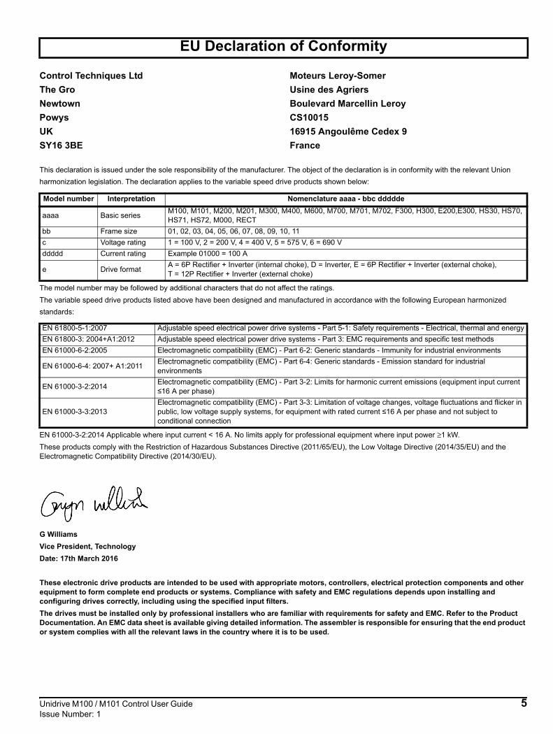
This declaration is issued under the sole responsibility of the manufacturer. The object of the declaration is in conformity with the relevant Union harmonization legislation. The declaration applies to the variable speed drive products shown below:
The model number may be followed by additional characters that do not affect the ratings.The variable speed drive products listed above have been designed and manufactured in accordance with the following European harmonized standards:
EN 61000-3-2:2014 Applicable where input current < 16 A. No limits apply for professional equipment where input power ≥1 kW.These products comply with the Restriction of Hazardous Substances Directive (2011/65/EU), the Low Voltage Directive (2014/35/EU) and the Electromagnetic Compatibility Directive (2014/30/EU).
G WilliamsVice President, TechnologyDate: 17th March 2016
These electronic drive products are intended to be used with appropriate motors, controllers, electrical protection components and other equipment to form complete end products or systems. Compliance with safety and EMC regulations depends upon installing and configuring drives correctly, including using the specified input filters.The drives must be installed only by professional installers who are familiar with requirements for safety and EMC. Refer to the Product Documentation. An EMC data sheet is available giving detailed information. The assembler is responsible for ensuring that the end product or system complies with all the relevant laws in the country where it is to be used.
EU Declaration of Conformity
Control Techniques LtdThe GroNewtownPowysUKSY16 3BE
Moteurs Leroy-SomerUsine des AgriersBoulevard Marcellin LeroyCS1001516915 Angoulême Cedex 9France
Model number Interpretation Nomenclature aaaa - bbc ddddde
aaaa Basic series M100, M101, M200, M201, M300, M400, M600, M700, M701, M702, F300, H300, E200,E300, HS30, HS70, HS71, HS72, M000, RECT
bb Frame size 01, 02, 03, 04, 05, 06, 07, 08, 09, 10, 11c Voltage rating 1 = 100 V, 2 = 200 V, 4 = 400 V, 5 = 575 V, 6 = 690 Vddddd Current rating Example 01000 = 100 A
e Drive format A = 6P Rectifier + Inverter (internal choke), D = Inverter, E = 6P Rectifier + Inverter (external choke), T = 12P Rectifier + Inverter (external choke)
EN 61800-5-1:2007 Adjustable speed electrical power drive systems - Part 5-1: Safety requirements - Electrical, thermal and energyEN 61800-3: 2004+A1:2012 Adjustable speed electrical power drive systems - Part 3: EMC requirements and specific test methodsEN 61000-6-2:2005 Electromagnetic compatibility (EMC) - Part 6-2: Generic standards - Immunity for industrial environments
EN 61000-6-4: 2007+ A1:2011 Electromagnetic compatibility (EMC) - Part 6-4: Generic standards - Emission standard for industrial environments
EN 61000-3-2:2014 Electromagnetic compatibility (EMC) - Part 3-2: Limits for harmonic current emissions (equipment input current ≤16 A per phase)
EN 61000-3-3:2013Electromagnetic compatibility (EMC) - Part 3-3: Limitation of voltage changes, voltage fluctuations and flicker in public, low voltage supply systems, for equipment with rated current ≤16 A per phase and not subject to conditional connection

Safety information
Product information
Mechanical installation
Electrical installation
Getting started
Basic parameters
Running the motor Optimization NV Media Card Advanced
parameters Diagnostics UL Listing
6 Unidrive M100 / M101 Control User Guide Issue Number: 1
1 Safety information1.1 Warnings, Cautions and Notes
A Note contains information which helps to ensure correct operation of the product.
1.2 Electrical safety - general warningThe voltages used in the drive can cause severe electrical shock and/or burns, and could be lethal. Extreme care is necessary at all times when working with or adjacent to the drive.Specific warnings are given at the relevant places in this Control User Guide.
1.3 System design and safety of personnel
The drive is intended as a component for professional incorporation into complete equipment or a system. If installed incorrectly, the drive may present a safety hazard.The drive uses high voltages and currents, carries a high level of stored electrical energy, and is used to control equipment which can cause injury.Close attention is required to the electrical installation and the system design to avoid hazards either in normal operation or in the event of equipment malfunction. System design, installation, commissioning/start-up and maintenance must be carried out by personnel who have the necessary training and experience. They must read this safety information and this Control User Guide carefully.The STOP functions of the drive do not isolate dangerous voltages from the output of the drive or from any external option unit. The supply must be disconnected by an approved electrical isolation device before gaining access to the electrical connections.None of the drive functions must be used to ensure safety of personnel, i.e. they must not be used for safety-related functions.Careful consideration must be given to the functions of the drive which might result in a hazard, either through their intended behavior or through incorrect operation due to a fault. In any application where a malfunction of the drive or its control system could lead to or allow damage, loss or injury, a risk analysis must be carried out, and where necessary, further measures taken to reduce the risk - for example, an over-speed protection device in case of failure of the speed control, or a fail-safe mechanical brake in case of loss of motor braking.
1.4 Environmental limitsInstructions in the Power Installation Guide regarding transport, storage, installation and use of the drive must be complied with, including the specified environmental limits. Drives must not be subjected to excessive physical force.
1.5 AccessDrive access must be restricted to authorized personnel only. Safety regulations which apply at the place of use must be complied with.
1.6 Fire protectionThe drive enclosure is not classified as a fire enclosure. A separate fire enclosure must be provided. For further information, refer to the relevant Power Installation Guide.
1.7 Compliance with regulationsThe installer is responsible for complying with all relevant regulations, such as national wiring regulations, accident prevention regulations and electromagnetic compatibility (EMC) regulations. Particular attention must be given to the cross-sectional areas of conductors, the selection of fuses or other protection, and protective ground (earth) connections.The Power Installation Guide contains instruction for achieving compliance with specific EMC standards.Within the European Union, all machinery in which this product is used must comply with the following directives:
2006/42/EC Safety of machinery.2014/30/EU: Electromagnetic Compatibility Directive.
1.8 MotorEnsure the motor is installed in accordance with the manufacturer’s recommendations. Ensure the motor shaft is not exposed.Standard squirrel cage induction motors are designed for single speed operation. If it is intended to use the capability of the drive to run a motor at speeds above its designed maximum, it is strongly recommended that the manufacturer is consulted first.Low speeds may cause the motor to overheat because the cooling fan becomes less effective. The motor should be installed with a protection thermistor. If necessary, an electric forced vent fan should be used.The values of the motor parameters set in the drive affect the protection of the motor. The default values in the drive should not be relied upon.It is essential that the correct value is entered in Pr 00.006 motor rated current. This affects the thermal protection of the motor.
1.9 Adjusting parametersSome parameters have a profound effect on the operation of the drive. They must not be altered without careful consideration of the impact on the controlled system. Measures must be taken to prevent unwanted changes due to error or tampering.
1.10 Electrical installation1.10.1 Electric shock riskThe voltages present in the following locations can cause severe electric shock and may be lethal:AC supply cables and connectionsOutput cables and connectionsMany internal parts of the drive, and external option unitsUnless otherwise indicated, control terminals are single insulated and must not be touched.
1.10.2 Stored chargeThe drive contains capacitors that remain charged to a potentially lethal voltage after the AC supply has been disconnected. If the drive has been energized, the AC supply must be isolated at least ten minutes before work may continue.
1.11 Hazard1.11.1 Falling hazardThe drive presents a falling or toppling hazard. This can cause injury to personnel and therefore should be handled with care.
A Warning contains information which is essential for avoiding a safety hazard.
A Caution contains information which is necessary for avoiding a risk of damage to the product or other equipment.
WARNING
CAUTION
NOTE

Safety information
Product information
Mechanical installation
Electrical installation
Getting started
Basic parameters
Running the motor Optimization NV Media Card Advanced
parameters Diagnostics UL Listing
2 Product information2.1 IntroductionOpen loop AC driveUnidrive M100 and Unidrive M101 deliver maximum machine performance with open loop vector and V/Hz induction motor control, for dynamic and efficient machine operation.Features• Value drive with quality and performance for open loop applications• NV Media Card for parameter copying and data storage• 24 Vdc backup supply (optional)
2.2 Model numberThe way in which the model numbers for the Unidrive M range are formed is illustrated below:Figure 2-1 Model number
Optional Build
Identification Label
Derivative Electrical Specifications
M100 - 03 4 00073
Unidrive M100
Product Line
Frame Size:
Current Rating:Heavy Duty current rating x 10
Drive Format:A - AC in AC out
Customer Code
01 A B 1 00
Customer Code:00 = 50 Hz
01 = 60 Hz
Reserved:
Conformal Coating:0 = Standard
IP / NEMA Rating:
1 = IP20 / NEMA 1
Brake Transistor:B = Brake
Cooling:
A = Air
Reserved
01ADocumentation
1
Documentation:
Voltage Rating:
2 - 200 V (200 - 240
- 400 V (380 - 480
- 575 V (500 - 575
- 690 V (500 - 690
10 %)
4
1 - 100 V (100 - 120 10 %)
±
10 %)
5
6 10 %)
10 %)
0 - Supplied separately1 - English2 - French3 - Italian4 - German5 - Spanish
Unidrive M100 / M101 Control User Guide 7Issue Number: 1

Safety information
Product information
Mechanical installation
Electrical installation
Getting started
Basic parameters
Running the motor Optimization NV Media Card Advanced
parameters Diagnostics UL Listing
2.3 Ratings
The drive is single rated.The rating is compatible with motors designed to IEC60034.The graph on the right illustrates Heavy Duty with respect to continuous current rating and short term overload limits.
Heavy DutyFor constant torque applications or applications which require a high overload capability, or full torque is required at low speeds (e.g. winders, hoists).The thermal protection is set to protect force ventilated induction motors by default.
NIf the application uses a self ventilated (TENV/TEFC) induction motor and increased thermal protection is required for speeds below 50 % base speed, then this can be enabled by setting Low Speed Thermal Protection Mode (04.025) = 1.
Operation of motor I2t protection
Motor I2t protection is fixed as shown below and is compatible with:• Self ventilated (TENV/TEFC) induction motors
Motor I2t protection defaults to be compatible with:• Forced ventilation induction motors
Available outputcurrent Overload limit -
Heavy Duty
Maximum continuous current - Heavy Duty
Motor ratedcurrent setin the driveHeavy Duty - with high
overload capability
NOTE
Motor totalcurrent (Pr 04.001)
as a percentageof motor rated
current
Motor speed as a percentage of base speed
100%
Max. permissiblecontinuouscurrent
100%
I t protection operates in this region2
70%
50%15%
Pr = 0Pr = 1
04.02504.025
Motor totalcurrent (Pr 04.001)
as a percentageof motor rated
current
Motor speed as a percentage of base speed
100%
Max. permissiblecontinuouscurrent
100%
I t protection operates in this region2
70%
50%
Pr = 0Pr = 1
04.02504.025
8 Unidrive M100 / M101 Control User Guide Issue Number: 1

Safety information
Product information
Mechanical installation
Electrical installation
Getting started
Basic parameters
Running the motor Optimization NV Media Card Advanced
parameters Diagnostics UL Listing
2.4 Operating modesThe drive is designed to operate in any of the following modes:1. Open loop mode
Open loop vector modeFixed V/F mode (V/Hz)Square V/F mode (V/Hz)
2.4.1 Open loop modeThe drive applies power to the motor at frequencies varied by the user. The motor speed is a result of the output frequency of the drive and slip due to the mechanical load. The drive can improve the speed control of the motor by applying slip compensation. The performance at low speed depends on whether V/F mode or open loop vector mode is selected.
Open loop vector mode The voltage applied to the motor is directly proportional to the frequency except at low speed where the drive uses motor parameters to apply the correct voltage to keep the flux constant under varying load conditions.Typically 100 % torque is available down to 1 Hz for a 50 Hz motor.
Fixed V/F modeThe voltage applied to the motor is directly proportional to the frequency except at low speed where a voltage boost is provided which is set by the user. This mode can be used for multi-motor applications.Typically 100 % torque is available down to 4 Hz for a 50 Hz motor.
Square V/F modeThe voltage applied to the motor is directly proportional to the square of the frequency except at low speed where a voltage boost is provided which is set by the user. This mode can be used for running fan or pump applications with quadratic load characteristics or for multi-motor applications. This mode is not suitable for applications requiring a high starting torque.
2.5 Keypad and displayThe keypad and display provide information to the user regarding the operating status of the drive and trip codes, and provide the means for changing parameters, stopping and starting the drive, and the ability to perform a drive reset.
(1) The Enter button is used to enter parameter view or edit mode, or to accept a parameter edit. (2 / 5) The Navigation button can be used to select individual parameters or to edit parameter values.(3) The Stop / Reset button is used to stop and reset the drive in keypad mode. It can also be used to reset the drive in terminal mode.(4) The Start button is used to start the drive in keypad mode.(6) The Escape button is used to exit from the parameter edit / view mode.(7) The Speed Reference Potentiometer is used to control the speed reference in keypad mode (only on Unidrive M101).(8) Units.(9) Run forward indicator.(10) Run reverse indicator.(11) Keypad reference indicator.
Figure 2-2 Unidrive M100 keypad detail Figure 2-3 Unidrive M101 keypad detail
1
2
34
5
6
V A Hz rpm %
17
8
10
V A Hz rpm %9
11
Unidrive M100 / M101 Control User Guide 9Issue Number: 1

Safety information
Product information
Mechanical installation
Electrical installation
Getting started
Basic parameters
Running the motor Optimization NV Media Card Advanced
parameters Diagnostics UL Listing
2.6 Nameplate descriptionFigure 2-4 Typical drive rating labels for size 2
Refer to Figure 2-1 Model number on page 7 for further information relating to the labels.
Date code formatThe date code is split into two sections: a letter followed by a number. The letter indicates the year, and the number indicates the week number (within the year) in which the drive was built.The letters go in alphabetical order, starting with A in 1991 (B in 1992, C in 1993 etc).
Example:A date code of W28 would correspond to week 28 of year 2013.
Model number
Refer toUser Guide
Date code
Inputvoltage Power rating
M100-022 00042 A
Modelnumber
Input voltage
Outputvoltage
Serialnumber
Inputfrequency
Powerrating
Date code
No. of phases &Typical input current
Heavy dutyoutput current
Approvals
M100-022 0042 A
5.4A
Patents: www.ctpatents.infoManuals: www.ctmanuals.info
0-550Hz
Outputfrequency
Key to approvals
CE approval Europe
C Tick approval Australia
UL / cUL approval USA & Canada
RoHS compliant Europe
Functional safety USA & Canada
EurAsian Conformity EurAsia
R
NOTE
10 Unidrive M100 / M101 Control User Guide Issue Number: 1

Safety information
Product information
Mechanical installation
Electrical installation
Getting started
Basic parameters
Running the motor Optimization NV Media Card Advanced
parameters Diagnostics UL Listing
2.7 OptionsFigure 2-5 Options available with the drive
1. AI-Backup Adaptor
Table 2-1 Adaptor Interface (AI) option module identification
1
Type Option module Name Further Details
Backup
AI-Backup adaptor +24 V Backup and SD card interfaceProvides a +24 V Backup supply input and SD card interface
AI-Smart adaptor+24 V Backup and SD card interfaceSupplied with 4 GB SD card for parameter copying and an input for 24 V Backup
Unidrive M100 / M101 Control User Guide 11Issue Number: 1

Safety information
Product information
Mechanical installation
Electrical installation
Getting started
Basic parameters
Running the motor Optimization NV Media Card Advanced
parameters Diagnostics UL Listing
12 Unidrive M100 / M101 Control User Guide Issue Number: 1
3 Mechanical installation3.1 Installing / removing optionFigure 3-1 Installing the AI-Backup adaptor
1. Identify the two plastic fingers on the underside of the AI-Backup adaptor (1) - then insert the two fingers into the corresponding slots in the spring-loaded sliding cover on the top of the drive.
2. Hold the adaptor firmly and push the spring loaded protective cover towards the back of the drive to expose the connector block (2) below.3. Press the adaptor downwards (3) until the adaptor connector locates into the drive connection below.
Figure 3-2 Removal of the AI-Backup Adaptor
• To remove the AI-Backup adaptor, pull it up away from the drive in the direction shown (1)
1 2
3
1

Safety information
Product information
Mechanical installation
Electrical installation
Getting started
Basic parameters
Running the motor Optimization NV Media Card Advanced
parameters Diagnostics UL Listing
4 Electrical installation4.1 24 Vdc supplyThe 24 Vdc supply connected to the +24 V supply terminals on the AI-Backup adaptor provides the following functions:• It can be used to clone or load parameters in order to pre-configure
drives when the line power supply is not available. The keypad can be used to setup parameters if required. However, the drive will be in the Under Voltage state unless the line power supply is enabled, therefore diagnostics may not be possible. (Power down save parameters are not saved when using the 24 V back-up power supply input).
The working voltage range of the 24 V back-up power supply is as follows:
Minimum and maximum voltage values include ripple and noise. Ripple and noise values must not exceed 5 %.Figure 4-1 Location of the 24 Vdc power supply connection on the
AI-Backup adaptor
4.2 Control connections4.2.1 GeneralTable 4-1 The control connections consist of:
Key:
All analog terminal functions can be programmed in menu 7.All digital terminal functions (including the relay) can be programmed in menu 8.
NAny signal cables which are carried inside the motor cable (i.e. motor thermistor, motor brake) will pick up large pulse currents via the cable capacitance. The shield of these signal cables must be connected to ground close to the point of exit of the motor cable, to avoid this noise current spreading through the control system.
0V 0V (connected internally to 0V common - Control terminal 1)
+ 24 V + 24 V Backup supply inputNominal operating voltage 24.0 VdcMinimum continuous operating voltage 19.2 VMaximum continuous operating voltage 30.0 VMinimum start up voltage 12.0 VMinimum power supply requirement at 24 V 20 WRecommended fuse 1 A, 50 Vdc
Function Qty Control parameters available Terminal number
Single ended analog input 1 Mode, offset, invert, scaling,
destination 2
Digital input 3 Destination, invert 11, 12, 13
Digital input / output 1 Input / output mode select, destination / source, invert 10
PWM or frequency output 1 Source, scaling, maximum
output frequency, mode 10
Relay 1 Source, invert 41, 42Drive enable 1 11+10 V User output 1 4+24 V User output 1 90V common 1 1
Destination parameter: Indicates the parameter which is being controlled by the terminal / function
Source parameter: Indicates the parameter being output by the terminal
Mode parameter:
Analog - indicates the mode of operation of the terminal, i.e. voltage 0-10 V, current 4-20 mA etc. Digital - indicates the mode of operation of the terminal, (the Drive Enable terminal is fixed in positive logic).
The control circuits are isolated from the power circuits in the drive by basic insulation (single insulation) only. The installer must ensure that the external control circuits are insulated from human contact by at least one layer of insulation (supplementary insulation) rated for use at the AC supply voltage.
If the control circuits are to be connected to other circuits classified as Safety Extra Low Voltage (SELV) (e.g. to a personal computer), an additional isolating barrier must be included in order to maintain the SELV classification.
If any of the digital inputs (including the drive enable input) are connected in parallel with an inductive load (i.e. contactor or motor brake) then suitable suppression (i.e. diode or varistor) should be used on the coil of the load. If no suppression is used then over voltage spikes can cause damage to the digital inputs and outputs on the drive.
WARNING
WARNING
CAUTION
NOTE
Unidrive M100 / M101 Control User Guide 13Issue Number: 1

Safety information
Product information
Mechanical installation
Electrical installation
Getting started
Basic parameters
Running the motor Optimization NV Media Card Advanced
parameters Diagnostics UL Listing
Figure 4-2 Default terminal functions
4.2.2 Control terminal specification
1 14 41 42
41
42
Relay(over-voltagecategory II)
Drive OK
Analog frequency
reference 1
1
4
2
0V common
+10 V
12
13
At zero frequency
Run forward
Run reverse
9
10
11Drive enable
+24 V
1 0V common
Function Common connection for all external devices
2 Analog input 1
Default function Frequency referenceType of input Unipolar single-ended analog voltage or unipolar currentMode controlled by… Pr 07.007Operating in voltage mode (default)Full scale voltage range 0V to +10 V ±3 %Maximum offset ±30 mVAbsolute maximum voltage range -18 V to +30 V relative to 0VInput resistance 100 kΩOperating in current mode
Current ranges 0 to 20 mA ±5 %, 20 to 0 mA ±5 %,4 to 20 mA ±5 %, 20 to 4 mA ±5 %
Maximum offset 250 µAAbsolute maximum voltage (reverse bias) -18 V to +30 V relative to 0VAbsolute maximum current 25 mAEquivalent input resistance 165 ΩCommon to all modesResolution 11 bitsSample rate 4 ms
4 +10 V user output
Default function Supply for external analog devicesNominal voltage 10.2 VVoltage tolerance ±3 %Maximum output current 5 mA
14 Unidrive M100 / M101 Control User Guide Issue Number: 1

Safety information
Product information
Mechanical installation
Electrical installation
Getting started
Basic parameters
Running the motor Optimization NV Media Card Advanced
parameters Diagnostics UL Listing
9 +24 V user output
Default function Supply for external digital devicesVoltage tolerance ±20 %Maximum output current 100 mAProtection Current limit and trip
10 Digital I/O 1
Default function AT ZERO FREQUENCY output
Type Positive logic digital input, positive logic voltage source output.PWM or frequency output modes can be selected.
Input / output mode controlled by … Pr 08.031Operating as in inputAbsolute maximum applied voltage range -8 V to +30 V relative to 0VImpedance 6.8 kΩInput threshold 10 V ±0.8 V (IEC 61131-2)Operating as an outputNominal maximum output current 50 mAMaximum output current 100 mA (total including +24 Vout)Common to all modesVoltage range 0V to +24 VSample rate 1 ms when routed to destinations Pr 06.035 or Pr 06.036, otherwise 4 ms
11 Digital Input 2
12 Digital Input 313 Digital Input 4
Terminal 11 default function DRIVE ENABLE inputTerminal 12 default function RUN FORWARD inputTerminal 13 default function RUN REVERSE inputType Positive logic only digital inputsVoltage range 0V to +24 VAbsolute maximum applied voltage range -18 V to +30 V relative to 0VImpedance 6.8 kΩInput threshold 10 V ±0.8 V (IEC 61131-2)Sample rate 1 ms when routed to destinations Pr 06.035 or Pr 06.036, otherwise 4 ms.
41Relay contacts
42Default function Drive OK indicatorContact voltage rating 240 Vac, Installation over-voltage category II
Contact maximum current rating2 A AC 240 V4 A DC 30 V resistive load0.5 A DC 30 V inductive load (L/R = 40 ms)
Contact minimum recommended rating 12 V 100 mAContact type Normally openDefault contact condition Closed when power applied and drive OKUpdate rate 1 ms
To prevent the risk of a fire hazard in the event of a fault, a fuse or other over-current protection must be installed in the relay circuit.
WARNING
Unidrive M100 / M101 Control User Guide 15Issue Number: 1

Safety information
Product information
Mechanical installation
Electrical installation
Getting started
Basic parameters
Running the motor Optimization NV Media Card Advanced
parameters Diagnostics UL Listing
5 Getting startedThis chapter introduces the user interfaces, menu structure and security levels of the drive.
5.1 Understanding the display5.1.1 KeypadThe keypad display consists of a 6 digit LED display. The display shows the drive status or the menu and parameter number currently being edited.The mm.ppp signifies the menu parameter number of the drive’s menus and parameter.The display also includes LED indicators showing units and status as shown in Figure 5-1.When the drive is powered up, the display will show the power up parameter defined by Parameter Displayed At Power-Up (11.022).
The values in the Status Mode Parameters (11.018 and 11.019) shown on the display when the drive is running, can be toggled by using the escape button.Figure 5-1 Unidrive M100 keypad detail
Table 5-1 Key to Figure 5-1
Figure 5-2 Unidrive M101 keypad detail
Table 5-2 Key to Figure 5-2
The red stop button is also used to reset the drive.
On the Unidrive M101, the speed reference potentiometer is used to adjust the keypad reference.
The parameter value is correctly displayed on the keypad display as shown in Table 5-3 below.Table 5-3 Keypad display formats
5.2 Keypad operation5.2.1 Control buttonsThe keypad consists of:• Up and down button - Used to navigate the parameter structure and
change parameter values.• Enter button - Used to change between parameter edit and view
mode, as well as entering data. • Escape button - Used to exit from parameter edit or view mode. In
parameter edit mode, if parameter values are edited and the escape button pressed, the parameter value will be restored to the value it had on entry to edit mode.
• Start button - Used to provide a 'Run' command if keypad mode is selected.
• Stop / Reset button - Used to reset the drive. In keypad mode can be used for 'Stop'.
1: Enter button 4: Start button (green)2: Up button 5: Down button3: Stop/Reset button (red) 6: Escape button
7: Speed reference potentiometer 10: Run reverse indicator8: Unit indicators 11: Keypad reference indicator9: Run forward indicator
NOTE
1
2
34
5
6
V A Hz rpm %
17
8
10
V A Hz rpm %9
11
NOTE
Display formats ValueStandard 100.99
Date 31.12.11 or 12.31.11Time 12.34.56
Character ABCDEFBinary 5
Version number 01.23.45
16 Unidrive M100 / M101 Control User Guide Issue Number: 1

Safety information
Product information
Mechanical installation
Electrical installation
Getting started
Basic parameters
Running the motor Optimization NV Media Card Advanced
parameters Diagnostics UL Listing
Figure 5-3 Display modes
Show previous or next parameter
or
- Press and release to go to next or previous parameter. Parameter flashes briefly then goes back to View.
- Holding or scrolls through each parameter within the menu.
Press and release.Show last slot / menu / param
selected
Press and release to edit Parameter
Menu select
Press or to select menu
Edited digits flash
Press and release to view
Parameter select
Press or to select parameter.
Edited digits flash
Press and release to edit
- Press and release to accept new value to be set. - Reset drive if required.- Execute action if required.
Press and release to
discard new value and return to original value
Press and release to edit Menu
Press and release to edit Parameter
View
Edit
Press or to select value
- Edited digit flashes- Holding or increases or decreases value.
- Modified value has a direct effect on the driveexcept routing parameters and special parameters.
- New value can be validated or discarded.
- Holding + or edit the next or previous digit.
Press and release to go back to status
Timeout240 s or hold
Press and release to edit Menu
Slot select(Only if option installed)
or
Press or to select _ or 1
Edited digit flashes
Press and release to edit Slot
Parameter format s.mm.ppps: _ or 0: for drive. If drive is selected then hide first digit and show only menu and parameter.
1: for optionmm: menu number (0 to 99)ppp: parameter number (0 to 999)
StatusIf Drive Status (Pr 10.101) = 4 (Run)Show value onlyIf Drive Status (Pr 10.101) <> 4Show status only
Go to Status if no option installed
- Holding and together sets value to zero.
Holding or timeout will discard new value and return
to original value.
or
or
Unidrive M100 / M101 Control User Guide 17Issue Number: 1

Safety information
Product information
Mechanical installation
Electrical installation
Getting started
Basic parameters
Running the motor Optimization NV Media Card Advanced
parameters Diagnostics UL Listing
The up and down buttons can only be used to move between menus if Pr 00.010 has been set to show 'ALL'. Refer to section 5.8 Parameter access level and security on page 20.Figure 5-4 Mode examples
1 Parameter view mode: Read write or Read only2 Status mode: Drive OK statusIf the drive is ok and the parameters are not being edited or viewed, the display will show one of the following:
inh', 'rdy' or status mode parameter value.3 Status mode: Trip statusWhen the drive is in trip condition, the display will indicate that the drive has tripped and the display will show the trip code. For further information regarding trip codes, refer to section 11.4 Trips, Sub-trip numbers on page 81.4 Status mode: Alarm statusDuring an 'alarm' condition the display flashes between the drive status parameter value and the alarm.
When changing the values of parameters, make a note of the new values in case they need to be entered again.
New parameter values must be saved to ensure that the new values apply after the drive has been power cycled. Refer to section 5.6 Saving parameters on page 19.
5.3 Menu structureThe drive parameter structure consists of menus and parameters.The drive initially powers up so that only Menu 0 can be viewed. The up and down arrow buttons are used to navigate between parameters and once Pr 00.010 has been set to 'All' the up and down buttons are used to navigate between menus.For further information refer to section 5.8 Parameter access level and security on page 20.The menus and parameters rollover in both directions i.e. if the last parameter is displayed, a further press will cause the display to rollover and show the first parameter.When changing between menus, the drive remembers which parameter was last viewed in a particular menu and thus displays that parameter.
5.4 Menu 0Menu 0 is used to bring together various commonly used parameters for basic easy set up of the drive. The parameters displayed in Menu 0 can be configured in Menu 22.Appropriate parameters are copied from the advanced menus into Menu 0 and thus exist in both locations.For further information, refer to Chapter 6 Basic parameters on page 21.Figure 5-5 Menu 0 copying
Do not change parameter values without careful consideration; incorrect values may cause damage or a safety hazard.
NOTE
3 4
1 2
WARNING
NOTE
NOTE
Menu 0
00.00400.00500.006
Menu 2
02.021
Menu 11
11.034
Menu 5
05.007
10.0AV4.1
AV
4.1
10.0
18 Unidrive M100 / M101 Control User Guide Issue Number: 1

Safety information
Product information
Mechanical installation
Electrical installation
Getting started
Basic parameters
Running the motor Optimization NV Media Card Advanced
parameters Diagnostics UL Listing
5.5 Advanced menus The advanced menus consist of groups or parameters appropriate to a specific function or feature of the drive. Menus 0 to 22 can be viewed on the Keypad. Table 5-4 Advanced menu descriptions
5.5.1 Display messagesThe following tables indicate the various possible mnemonics which can be displayed by the drive and their meaning.
Table 5-5 Status indications
5.5.2 Alarm indicationsAn alarm is an indication given on the display by alternating the alarm string with the drive status string on the display. Alarms strings are not displayed when a parameter is being edited.
Table 5-6 Alarm indications
5.6 Saving parametersWhen changing a parameter in Menu 0, the new value is saved when
pressing the Enter button to return to parameter view mode from parameter edit mode.If parameters have been changed in the advanced menus, then the change will not be saved automatically. A save function must be carried out.
Procedure1. Select ‘Save' in Pr mm.000 (alternatively enter a value of 1001 in
Pr mm.000)
• Press the red reset button
5.7 Restoring parameter defaultsRestoring parameter defaults by this method saves the default values in the drives memory. User security status (00.010) and User security code (00.025) are not affected by this procedure).
Procedure1. Ensure the drive is not enabled, i.e. drive is in inhibit or under
voltage state.2. Select 'Def.50’ or 'Def.60' in Pr mm.000. (alternatively, enter 1233
(50 Hz settings) or 1244 (60 Hz settings) in Pr mm.000).
• Press the red reset button
Menu Description
0 Commonly used basic set up parameters for quick / easy programming
1 Frequency reference2 Ramps3 Frequency control4 Torque and current control5 Motor control6 Sequencer and clock7 Analog I/O8 Digital I/O
10 Status and trips11 Drive set-up and identification22 Menu 0 set-up
String DescriptionDrive
output stage
inh
The drive is inhibited and cannot be run. The Drive Enable signal is not applied to the drive enable terminal or Pr 06.015 is set to 0. The other conditions that can prevent the drive from enabling are shown as bits in Enable Conditions (06.010)
Disabled
rdyThe drive is ready to run. The drive enable is active, but the drive inverter is not active because the final drive run is not active
Disabled
StoP The drive is stopped / holding zero speed. EnabledS.Loss Supply loss condition has been detected Enableddc inj The drive is applying dc injection braking Enabled
ErThe drive has tripped and no longer controlling the motor. The trip code appears on the display.
Disabled
UV The drive is in the under voltage state either in low voltage or high voltage mode. Disabled
HEAt The motor pre-heat function is active. Enabled
Alarm string Description
br.resBrake resistor overload. Braking Resistor Thermal Accumulator (10.039) in the drive has reached 75.0 % of the value at which the drive will trip.
OV.LdMotor Protection Accumulator (04.019) in the drive has reached 75.0 % of the value at which the drive will trip and the load on the drive is >100 %.
d.OV.LdDrive over temperature. Percentage Of Drive Thermal Trip Level (07.036) in the drive is greater than 90 %.
tuning The autotune procedure has been initialized and an autotune in progress.
LS Limit switch active. Indicates that a limit switch is active and that is causing the motor to be stopped.
Lo.AC Low voltage mode. See Low AC Alarm (10.107).
I.AC.Lt Current limit active. See Current Limit Active (10.009).
24.LoSt 24 V backup not present. See 24V Alarm Loss Enable (11.098).
Unidrive M100 / M101 Control User Guide 19Issue Number: 1

Safety information
Product information
Mechanical installation
Electrical installation
Getting started
Basic parameters
Running the motor Optimization NV Media Card Advanced
parameters Diagnostics UL Listing
5.8 Parameter access level and securityThe parameter access level determines whether the user has access to Menu 0 only or to all the advanced menus (Menus 1 to 22) in addition to Menu 0.The User Security determines whether the access to the user is read only or read write.Both the User Security and Parameter Access Level can operate independently of each other as shown in Table 5-7.Table 5-7 Parameter access level and security
The default settings of the drive are Parameter Access Level Menu 0 and user Security Open i.e. read / write access to Menu 0 with the advanced menus not visible.
5.8.1 User Security Level / Access LevelThe drive provides a number of different levels of security that can be set by the user via User Security Status (00.010); these are shown in the table below.
5.8.2 Changing the User Security Level /Access Level
The security level is determined by the setting of Pr 00.010 or Pr 11.044. The Security Level can be changed through the keypad even if the User Security Code has been set.
5.8.3 User Security CodeThe User Security Code, when set, prevents write access to any of the parameters in any menu.
Setting User Security CodeEnter a value between 1 and 9999 in Pr 00.025 and press the button; the security code has now been set to this value. In order to activate the security, the Security level must be set to desired level in Pr 00.010. When the drive is reset, the security code will have been activated and the drive returns to Menu 0. The value of Pr 00.025 will return to 0 in order to hide the security code.
Unlocking User Security CodeSelect a parameter that need to be edited and press the button, the display will now show ‘Co’. Use the arrow buttons to set the security
code and press the button. With the correct security code entered, the display will revert to the parameter selected in edit mode.If an incorrect security code is entered, the following message ‘Co.Err’ is displayed, and the display will revert to parameter view mode.
Disabling User SecurityUnlock the previously set security code as detailed above. Set Pr 00.025
to 0 and press the button. The User Security has now been disabled, and will not have to be unlocked each time the drive is powered up to allow read / write access to the parameters.
5.9 Displaying parameters with non-default values only
By selecting 'diff.d' in Pr mm.000 (Alternatively, enter 12000 in Pr mm.000), the only parameters that will be visible to the user will be those containing a non-default value. This function does not require a drive reset to become active. In order to deactivate this function, return to Pr mm.000 and select 'none' (alternatively enter a value of 0). Please note that this function can be affected by the access level enabled, refer to section 5.8 Parameter access level and security on page 20 for further information regarding access level.
5.10 Displaying destination parameters onlyBy selecting 'dest' in Pr mm.000 (Alternatively enter 12001 in Pr mm.000), the only parameters that will be visible to the user will be destination parameters. This function does not require a drive reset to become active. In order to deactivate this function, return to Pr mm.000 and select 'none' (alternatively enter a value of 0).Please note that this function can be affected by the access level enabled, refer to section 5.8 Parameter access level and security on page 20 for further information regarding access level.
User security status
(00.010)
Access levelUser
security(00.025)
Menu 0 status
Advanced menu status
0 Menu 0 None RW Not visible
1 All Menus None RW RW
2 Read-only Menu 0
Open RW Not visibleClosed RO Not visible
3 Read-onlyOpen RW RWClosed RO RO
4 Status onlyOpen RW RWClosed Not visible Not visible
5 No accessOpen RW RWClosed Not visible Not visible
User Security Status
(Pr 00.010)Description
LEVEL.0 (0) All writable parameters are available to be edited but only parameters in Menu 0 are visible
ALL (1) All parameters are visible and all writable parameters are available to be edited
r.only.0 (2) Access is limited to Menu 0 parameters only. All parameters are read-only
r.only.A (3) All parameters are read-only however all menus and parameters are visible
Status (4) The keypad remains in status mode and no parameters can be viewed or edited
no.acc (5) The keypad remains in status mode and no parameters can be viewed or edited.
20 Unidrive M100 / M101 Control User Guide Issue Number: 1

Safety information
Product information
Mechanical installation
Electrical installation
Getting started
Basic parameters
Running the motor Optimization NV Media Card Advanced
parameters Diagnostics UL Listing
6 Basic parameters
6.1 Parameter ranges and Variable minimum/maximums:Some parameters in the drive have a variable range with a variable minimum and a variable maximum value which is dependent on one of the following:• The settings of other parameters• The drive rating• The drive mode• Combination of any of the above
For more information please see section 10.1 Parameter ranges and Variable minimum/maximums: on page 47.
Menu 0 is used to bring together various commonly used parameters for basic easy set up of the drive. All the parameters in Menu 0 appear in other menus in the drive (denoted by …). Menu 22 can be used to configure the parameters in Menu 0.
Unidrive M100 / M101 Control User Guide 21Issue Number: 1

Safety information
Product information
Mechanical installation
Electrical installation
Getting started
Basic parameters
Running the motor Optimization NV Media Card Advanced
parameters Diagnostics UL Listing
6.2 Menu 0: Basic parameters
* With Unidrive M101, the default is PAd (5).** Following a rotating autotune Pr 00.009 05.010 is continuously written by the drive, calculated from the value of Stator Inductance (Pr 05.025). To manually enter a value into Pr 00.009 05.010, Pr 05.025 will need to be set to 0. Refer to the description of Pr 05.010 in the Parameter Reference Guide for further details.
ParameterRange ( ) Default ( )
TypeOL OL
00.001 Minimum Reference Clamp 01.007 VM_NEGATIVE_REF_CLAMP 1 Hz 0.00 Hz RW Num US
00.002 Maximum Reference Clamp 01.006 VM_POSITIVE_REF_CLAMP Hz 50 Hz default: 50.00 Hz60 Hz default: 60.00 Hz RW Num US
00.003 Acceleration Rate 1 02.011 0.0 to VM_ACCEL_RATE s / 100 Hz 5.0 s / 100 Hz RW Num US00.004 Deceleration Rate 1 02.021 0.0 to VM_ACCEL_RATE s / 100 Hz 10.0 s / 100 Hz RW Num US
00.005 Drive Configuration 11.034AV (0), AI (1), AV.Pr (2), AI.Pr (3), PrESEt (4), PAd (5), PAd.rEF (6),
E.Pot (7), torquE (8)AV (0)* RW Txt PT US
00.006 Motor Rated Current 05.007 0.00 to VM_RATED_CURRENT A Maximum Heavy Duty Rating(11.032) A RW Num RA US
00.007 Motor Rated Speed 05.008 0.0 to 33000.0 rpm
50 Hz default: 1500.0 rpm
60 Hz default: 1800.0 rpm
RW Num US
00.008 Motor Rated Voltage 05.009 0 to VM_AC_VOLTAGE_SET V
110 V drive: 230 V200 V drive: 230 V
400 V drive 50 Hz: 400 V400 V drive 60 Hz: 460 V
575 V drive: 575 V690 V drive: 690 V
RW Num RA US
00.009 Motor Rated Power Factor** 05.010 0.00 to 1.00 0.85 RW Num RA US
00.010 User Security Status 11.044 LEVEL.0 (0), ALL (1), r.only.0 (2),r.only.A (3), Status (4), no.acc (5) LEVEL.0 (0) RW Num ND NC PT
00.015 Jog Reference 01.005 0.00 to 300.00 Hz 1.50 Hz RW Num US
00.016 Analog Input 1 Mode 07.0074-20.S (-6), 20-4.S (-5), 4-20.L (-4), 20-4.L (-3),
4-20.H (-2), 20-4.H (-1), 0-20 (0), 20-0 (1), 4-20.tr (2), 20-4.tr (3), 4-20 (4), 20-4 (5), Volt (6)
Volt (6) RW Txt US
00.017 Bipolar Reference Enable 01.010 Off (0) or On (1) Off (0) RW Bit US00.018 Preset Reference 1 01.021 VM_SPEED_FREQ_REF Hz 0.00 Hz RW Num US00.025 User Security Code 11.030 0 to 9999 0 RW Num ND NC PT US
00.027 Power-up Keypad Control Mode Reference 01.051 Reset (0), Last (1), Preset (2) Reset (0) RW Txt US
00.028 Ramp Mode Select 02.004 Fast (0), Std (1), Std.bst (2), Fst.bst (3) Std (1) RW Txt US00.030 Parameter Cloning 11.042 NonE (0), rEAd (1), Prog (2), Auto (3), boot (4) NonE (0) RW Txt NC US
00.031 Stop Mode 06.001 Coast (0), rp (1), rp.dc I (2), dc I (3), td.dc I (4),dis (5), rp (1) RW Txt US
00.032 Dynamic V to F Select 05.013 0 to 1 0 RW Num US
00.033 Catch A Spinning Motor 06.009 dis (0), Enable (1), Fr.Only (2),Rv.Only (3) dis (0) RW Txt US
00.035 Digital Output 1 Control 08.091 0 to 21 0 RW US
00.037 Maximum Switching Frequency 05.018 0.667 (0), 1 (1), 2 (2), 3 (3), 4 (4),
6 (5), 8 (6), 12 (7), 16 (8) kHz 3 (3) kHz RW Txt US
00.038 Autotune 05.012 0 to 2 0 RW Num NC US
00.039 Motor Rated Frequency 05.006 0.0 to 550.00 Hz 50 Hz: 50.00 Hz60 Hz: 60.00 Hz RW Num RA US
00.040 Number of Motor Poles 05.011 Auto (0) to 32 (16) Auto 0 RW Num US
00.041 Control Mode 05.014 Ur.S (0), Ur (1), Fd (2), Ur.Auto (3), Ur.I (4), SrE (5), Fd.tAP (6) Ur.I (4) RW Txt US
00.042 Low Frequency Voltage Boost 05.015 0.0 to 25.0 % 3.0 % RW Num US00.069 Spin Start Boost 05.040 0.0 to 10.0 1.0 RW US00.076 Action on Trip Detection 10.037 0 to 31 0 RW US
00.077 Maximum Heavy Duty Current Rating 11.032 0.00 to 9999.99 A RO Num ND NC PT
00.078 Software Version 11.029 0 to 999999 RO ND NC PT00.079 User Drive Mode 11.031 OPEn.LP (1) OPEn.LP (1) RW Txt ND NC PT US
RW Read / Write RO Read only Num Number parameter Bit Bit parameter Txt Text string Bin Binary parameter FI FilteredND No default value NC Not copied PT Protected parameter RA Rating dependent US User save PS Power-down save DE DestinationIP IP address Mac Mac address Date Date parameter Time Time parameter
22 Unidrive M100 / M101 Control User Guide Issue Number: 1

Safety information
Product information
Mechanical installation
Electrical installation
Getting started
Basic parameters
Running the motor Optimization NV Media Card Advanced
parameters Diagnostics UL Listing
Unidrive M100 / M101 Control User Guide 23Issue Number: 1

Safety information
Product information
Mechanical installation
Electrical installation
Getting started
Basic parameters
Running the motor Optimization NV Media Card Advanced
parameters Diagnostics UL Listing
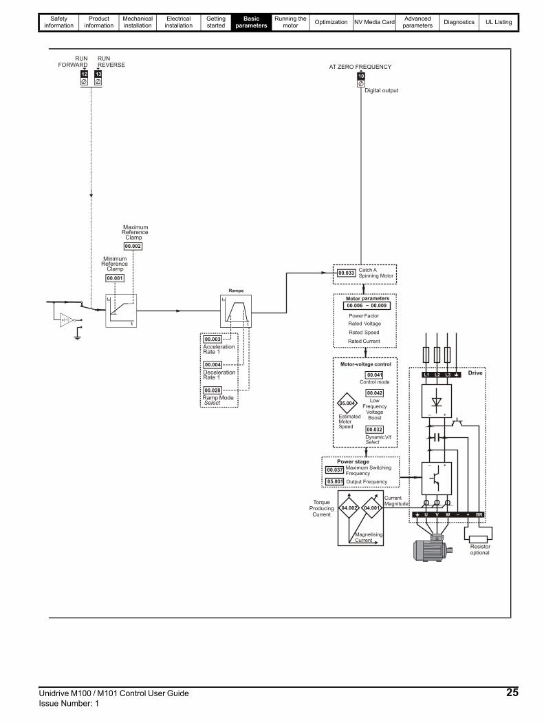
Figure 6-1 Menu 0 logic diagram
2
Analog reference
Keypad reference
00.XXX
00.XXX
Key
Read-write (RW)parameter
Read-only (RO)parameter
Inputterminals
Outputterminals
XX
XX
The parameters are all shown in their default settings
00.018PresetReference 1
Preset frequencyreference
0
5
00.017
Bipolar
Analog input 1 Analog input1 mode
ReferenceEnable
AV
Pr
Pad
Pad.Ref
torque
6
7
8
01.015 Pr
set
01.050
101.050
00.005
DriveConfiguration
AI
AV.Pr
AI.Pr
1
2
3
4
00.016
24 Unidrive M100 / M101 Control User Guide Issue Number: 1
Safety information
Product information
Mechanical installation
Electrical installation
Getting started
Basic parameters
Running the motor Optimization NV Media Card Advanced
parameters Diagnostics UL Listing
10
AT ZERO FREQUENCY
RUNREVERSE
RUNFORWARD
MinimumReference
Reference
Clamp
00.001
00.002
12 13
Ramps
AccelerationRate 1
DecelerationRate 1
Ramp ModeSelect
00.003
00.004
00.028
Maximum
LowFrequency
VoltageBoost
Clamp
Digital output
Power stage _ +
_ +
U V W
Resistoroptional
Drive
00.037
05.001
Maximum SwitchingFrequency
Output Frequency
TorqueProducing
Current
CurrentMagnitude
MagnetisingCurrent
+ BR_
04.002 04.001
L3L2L1
00.033
Power Factor
Rated Voltage
Rated Speed
Rated Current
00.006 ~ 00.009
Motor parameters
x(-1)
Unidrive M100 / M101 Control User Guide 25Issue Number: 1

Safety information
Product information
Mechanical installation
Electrical installation
Getting started
Basic parameters
Running the motor Optimization NV Media Card Advanced
parameters Diagnostics UL Listing
6.3 Parameter descriptions6.3.1 Pr mm.000Pr mm.000 is available in all menus, commonly used functions are provided as text strings in Pr mm.000 shown in Table 6-1. The functions in Table 6-1 can also be selected by entering the appropriate numeric values (as shown in Table 6-2) in Pr mm.000. For example, enter 4001 in Pr mm.000 to store drive parameters on an NV media card.
Table 6-1 Commonly used functions in xx.000
Table 6-2 Functions in Pr mm.000
* See Chapter 9 NV Media Card on page 40 for more information on these functions.** These functions do not require a drive reset to become active. All other functions require a drive reset to initiate the function. Equivalent values and strings are also provided in the table above.
Value Equivalent value String Action
0 0 None No action
1001 1 SAVE Save drive parameters to non-volatile memory
6001 2 LOAd.1 Load the data from file 1 on a non-volatile media card into the drive provided it is a parameter file
4001 3 SAVE.1 Store the drive parameters in file 1 on a non-volatile media card
6002 4 LOAd.2 Load the data from file 2 on a non-volatile media card into the drive provided it is a parameter file
4002 5 SAVE.2 Store the drive parameters in file 2 on a non-volatile media card
6003 6 LOAd.3 Load the data from file 3 on a non-volatile media card into the drive provided it is a parameter file
4003 7 SAVE.3 Store the drive parameters in file 3 on a non-volatile media card
12000 8 diff.d Only display parameters that are different from their default value
12001 9 dest Only display parameters that are used to set-up destinations
1233 10 def.50 Load 50 Hz defaults
1244 11 def.60 Load 60 Hz defaults
Value Action1000 Save parameters when Under Voltage Active (Pr 10.016) is not active. 1001 Save parameters under all conditions1233 Load standard (50 Hz) defaults1244 Load US (60 Hz) defaults1299 Reset St.HF trip.2001* Create a boot file on a non-volatile media card based on the present drive parameters4yyy* NV media card: Transfer the drive parameters to parameter file yyy6yyy* NV media card: Load the drive parameters from parameter file yyy 7yyy* NV media card: Erase file yyy 8yyy* NV Media card: Compare the data in the drive with file yyy9555* NV media card: Clear the warning suppression flag9666* NV media card: Set the warning suppression flag9777* NV media card: Clear the read-only flag9888* NV media card: Set the read-only flag
12000** Only display parameters that are different from their default value. This action does not require a drive reset.12001** Only display parameters that are used to set-up destinations (i.e. DE format bit is 1). This action does not require a drive reset.
26 Unidrive M100 / M101 Control User Guide Issue Number: 1

Safety information
Product information
Mechanical installation
Electrical installation
Getting started
Basic parameters
Running the motor Optimization NV Media Card Advanced
parameters Diagnostics UL Listing
6.4 Control terminal configurations and wiring
* With Unidrive M101, the default is PAd (5).
Table 6-3 Parameter changes when drive configuration is changed
Note 1:
If last default setting was 50 Hz or in PAd or PAd.rEF configuration: Pr 06.004 is 0.If last default setting was 60 Hz: Pr 06.004 is 4.Note 2:
If last default setting was 50 Hz or in PAd or PAd.rEF configuration: Pr 08.022 is 06.038.If last default setting was 60 Hz: Pr 08.022 is 06.039.Note 3:If last default setting was 50 Hz: Pr 08.024 is 06.032If last default setting was 60 Hz: Pr 08.024 is 06.031.
This parameter is used to automatically setup the user programmable area in the advanced parameter set according to drive configurations. Other default values may also be changed by drive configuration. Parameters are stored in EEPROM automatically following a configuration change. Defaults loaded are defined by Defaults Previously Loaded.
00.005 Drive ConfigurationRW Txt PT US
OLAV (0), AI (1), AV.Pr (2), AI.Pr (3), PrESEt (4), PAd (5), PAd.rEF (6),
torquE (8)AV (0)*
Parameternumber Description
Drive configuration
AV AI AV.Pr AI.Pr PrESEt PAd PAd.rEF torquE01.014 Reference select 0 0 1 1 3 4 6 406.004 Start/stop logic Note 1 Note 1 Note 1 Note 1 Note 1 Note 1 Note 1 Note 1
07.007 Analog input 1 mode 6 4 6 4 6 6 6 6
07.010 Analog input 1 destination 01.036 01.036 01.036 01.036 01.036 01.036 01.036 04.008
07.051 Analog input 1 control 0 0 0 0 0 0 0 0
08.021Digital IO 1
source/ destination
10.003 10.003 01.046 01.046 01.046 10.003 10.003 10.003
08.022 Digital input 2 destination Note 2 Note 2 Note 2 Note 2 Note 2 Note 2 Note 2 Note 2
08.024 Digital input 4 destination Note 3 Note 3 01.045 01.045 01.045 06.032 06.032 04.011
08.031 Digital I/O 1 mode 1 1 0 0 0 1 1 1
08.081 Digital input 1 control 0 0 0 0 0 0 0 0
08.082 Digital input 2 control 0 0 0 0 0 0 0 0
08.084 Digital input 4 control 0 0 0 0 0 0 0 0
08.091 Digital output 1 control 0 0 0 0 0 0 0 0
Value Text Description0 AV Analog input 1 (voltage) 1 AI Analog input 1 (current) 2 AV.Pr Analog input 1 (voltage) or 3 presets selected by terminal3 AI.Pr Analog input 1 (current) or 3 presets selected by terminal4 PrESEt Four presets selected by terminal5 PAd Keypad reference6 PAd.rEF Keypad reference with terminal control8 torquE Torque mode, Analog input 1 (voltage torque reference) selected by terminal
Unidrive M100 / M101 Control User Guide 27Issue Number: 1

Safety information
Product information
Mechanical installation
Electrical installation
Getting started
Basic parameters
Running the motor Optimization NV Media Card Advanced
parameters Diagnostics UL Listing
Action will only occur if the drive is inactive and no User Actions are running. Otherwise, the parameter will return to its pre altered value on exit from edit mode. All parameters are saved if this parameter changes.Figure 6-2 Pr 00.005 = AV (50 Hz)
Figure 6-3 Pr 00.005 = AV (60 Hz)
Figure 6-4 Pr 00.005 = AI (50 Hz)
Figure 6-5 Pr 00.005 = AI (60 Hz)
1
2
4
9
0 V
Voltage speedreference input (AI 1)
Digital output(zero frequency)10
11
12
13
Drive enable
Run forward
Run reverse
+ 10 V output
+ 24 V output
10k
1
2
4
9
0 V
Voltage speedreference input (AI 1)
Digital output(zero frequency)10
11
12
13
Not stop
Run
Jog forward
+ 10 V output
+ 24 V output
10k
1
2
4
9
0 V
Current speedreference input (AI 1)
Digital output(zero frequency)10
11
12
13
Drive enable
Run forward
Run reverse
+ 10 V output
+ 24 V output
Current speedreference input
1
2
4
9
0 V
Current speedreference input (AI 1)
Digital output(zero frequency)10
11
12
13
Not stop
Run
Jog forward
+ 10 V output
+ 24 V output
Current speedreference input
28 Unidrive M100 / M101 Control User Guide Issue Number: 1

Safety information
Product information
Mechanical installation
Electrical installation
Getting started
Basic parameters
Running the motor Optimization NV Media Card Advanced
parameters Diagnostics UL Listing
Figure 6-6 Pr 00.005 = AV.Pr (50 Hz)
Figure 6-7 Pr 00.005 = AV.Pr (60 Hz)
Figure 6-8 Pr 00.005 = AI.Pr (50 Hz)
Figure 6-9 Pr 00.005 = AI.Pr (60 Hz)
* Refer to section 10.2 Menu 1: Frequency reference on page 52.
1
2
4
9
0 V
10k Voltage speedreference input (AI 1)
Reference select
Reference select
10
11
12
13
Drive enable
Run forward
+ 10 V output
+ 24 V output
Terminal 10 Terminal 13 Reference selected0 0 Analog reference 1*0 1 Preset speed 2*1 0 Preset speed 3*1 1 Preset speed 4*
1
2
4
9
0 V
10k Voltage speedreference input (AI 1)
Reference select
Reference select
10
11
12
13
Not stop
Run
+ 10 V output
+ 24 V output
Terminal 10 Terminal 13 Reference selected0 0 Analog reference 1*0 1 Preset speed 2*1 0 Preset speed 3*1 1 Preset speed 4*
1
2
4
9
0 V
Current speedreference input (AI 1)
Reference select
Reference select
10
11
12
13
Drive enable
Run forward
+ 10 V output
+ 24 V output
Current speedreference input
Terminal 10 Terminal 13 Reference selected0 0 Analog reference 1*0 1 Preset speed 2*1 0 Preset speed 3*1 1 Preset speed 4*
1
2
4
9
0 V
Current speedreference input (AI 1)
Reference select
Reference select
10
11
12
13
Not stop
Run
+ 10 V output
+ 24 V output
Current speedreference input
Terminal 10 Terminal 13 Reference selected0 0 Analog reference 1*0 1 Preset speed 2*1 0 Preset speed 3*1 1 Preset speed 4*
Unidrive M100 / M101 Control User Guide 29Issue Number: 1

Safety information
Product information
Mechanical installation
Electrical installation
Getting started
Basic parameters
Running the motor Optimization NV Media Card Advanced
parameters Diagnostics UL Listing
Figure 6-10 Pr 00.005 = PrESEt (50 Hz)
Figure 6-11 Pr 00.005 = PrESEt (60 Hz)
* Refer to section 10.2 Menu 1: Frequency reference on page 52.
Figure 6-12 Pr 00.005 = PAd (50 Hz & 60 Hz)
Figure 6-13 Pr 00.005 = PAd.rEF (50 Hz & 60 Hz)
1
2
4
9
0 V
Voltage speedreference input (AI 1)
Reference select
Reference select
10
11
12
13
Drive enable
Run forward
+ 10 V output
+ 24 V output
Terminal 10 Terminal 13 Reference selected0 0 Preset speed 1*0 1 Preset speed 2*1 0 Preset speed 3*1 1 Preset speed 4*
1
2
4
9
0 V
Voltage speedreference input (AI 1)
Reference select
Reference select
10
11
12
13
Not stop
Run
+ 10 V output
+ 24 V outputTerminal 10 Terminal 13 Reference selected
0 0 Preset speed 1*0 1 Preset speed 2*1 0 Preset speed 3*1 1 Preset speed 4*
1
2
4
9
0 V
Voltage speedreference input (AI 1)
Digital output(zero frequency)
Run reverse
10
11
12
13
Drive enable
Run forward
+ 10 V output
+ 24 V output
1
2
4
9
0 V
Voltage speedreference input (AI 1)
Digital output(zero frequency)
Run reverse
10
11
12
13
Drive enable
Run forward
+ 10 V output
+ 24 V output
30 Unidrive M100 / M101 Control User Guide Issue Number: 1

Safety information
Product information
Mechanical installation
Electrical installation
Getting started
Basic parameters
Running the motor Optimization NV Media Card Advanced
parameters Diagnostics UL Listing
Figure 6-14 Pr 00.005 = torquE (50 Hz)
Figure 6-15 Pr 00.005 = torquE (60 Hz)
1
2
4
9
0 V
10k Torque referenceinput (AI 1)
Digital output(zero frequency)
Torque mode select
10
11
12
13
Drive enable
Run forward
+ 10 V output
+ 24 V output When torque mode is selected and the drive is connected to an unloaded motor, the motor speed may increase rapidly to the maximum speed (Pr 00.002 +10 %)WARNING
1
2
4
9
0 V
10k Torque referenceinput (AI 1)
Digital output(zero frequency)
Torque modeselect
10
11
12
13
Not stop
Run
+ 10 V output
+ 24 V outputWhen torque mode is selected and the drive is connected to an unloaded motor, the motor speed may increase rapidly to the maximum speed (Pr 00.002 +10 %)WARNING
Unidrive M100 / M101 Control User Guide 31Issue Number: 1
Safety information
Product information
Mechanical installation
Electrical installation
Getting started
Basic parameters
Running the motor Optimization NV Media Card Advanced
parameters Diagnostics UL Listing
7 Running the motorThis chapter takes the new user through all the essential steps to running a motor for the first time, in each of the possible operating modes.For information on tuning the drive for the best performance, see Chapter 8 Optimization on page 35.
7.1 Quick start connections7.1.1 Basic requirements This section shows the basic connections which must be made for the drive to run in the required mode. For minimal parameter settings to run in each mode please see the relevant part of section 7.2 Quick start commissioning / start-up on page 34. Table 7-1 Minimum control connection requirements for each
control mode
Ensure that no damage or safety hazard could arise from the motor starting unexpectedly.
The values of the motor parameters affect the protection of the motor.The default values in the drive should not be relied upon.It is essential that the correct value is entered in Pr 00.006 Motor Rated Current. This affects the thermal protection of the motor.
If the drive is started using the keypad it will run to the speed defined by the keypad reference (Pr 01.017). This may not be acceptable depending on the application. The user must check in Pr 01.017 and ensure that the keypad reference has been set to 0.
If the intended maximum speed affects the safety of the machinery, additional independent over-speed protection must be used.
Drive control method Requirements
Terminal modeDrive enable Speed / Torque referenceRun forward / Run reverse
Keypad mode Drive enable
WARNING
CAUTION
CAUTION
WARNING
32 Unidrive M100 / M101 Control User Guide Issue Number: 1

Safety information
Product information
Mechanical installation
Electrical installation
Getting started
Basic parameters
Running the motor Optimization NV Media Card Advanced
parameters Diagnostics UL Listing
Figure 7-1 Minimum connections to get the motor running in any operating mode
L1 L2 L3
Fuses
L1 L2 L3 U V W
U V W
10
11
12
13
9
+ BR
+10 V24 V
Run FWD
Drive enable
Run REV
Brakingresistor
(optional)
Induction motor
4
2
1 FrequencyReferenceinput
0V
1
1
Terminal
Mode
Keypad
Mode
Thermal overload for braking resistorto protect against fire risk. This must bewired to interrupt the AC supply in theevent of a fault.
Unidrive M100 / M101 Control User Guide 33Issue Number: 1

Safety information
Product information
Mechanical installation
Electrical installation
Getting started
Basic parameters
Running the motor Optimization NV Media Card Advanced
parameters Diagnostics UL Listing
7.2 Quick start commissioning / start-up7.2.1 Open loop
Action Detail
Before power-up
Ensure:• The drive enable signal is not given (terminal 11)• Run signal is not given• Motor is connected
Power-up the driveEnsure:• Drive displays ‘inh’If the drive trips, see Chapter 11 Diagnostics on page 80.
Enter motor nameplate details
Enter:• Motor rated frequency in Pr 00.039 (Hz)• Motor rated current in Pr 00.006 (A)• Motor rated speed in Pr 00.007 (rpm)• Motor rated voltage in Pr 00.008 (V) - check if or connection
Set maximum frequency
Enter:• Maximum frequency in Pr 00.002 (Hz)
Set acceleration / deceleration rates
Enter:• Acceleration rate in Pr 00.003 (s/100 Hz)• Deceleration rate in Pr 00.004 (s/100 Hz) (If braking resistor is installed, set Pr 00.028 = FAST. Also
ensure Pr 10.030 and Pr 10.031 and Pr 10.061 are set correctly, otherwise premature ‘It.br’ trips may be seen).
Autotune
The drive is able to perform either a stationary or a rotating autotune. The motor must be at a standstill before an autotune is enabled. A rotating autotune should be used whenever possible so the measured value of power factor of the motor is used by the drive.
• A stationary autotune can be used when the motor is loaded and it is not possible to uncouple the load from the motor shaft. A stationary autotune measures the stator resistance of the motor and the dead time compensation for the drive. These are required for good performance in vector control modes. A stationary autotune does not measure the power factor of the motor so the value on the motor nameplate must be entered into Pr 00.009.
• A rotating autotune should only be used if the motor is uncoupled. A rotating autotune first performs a stationary autotune before rotating the motor at 2/3 base speed in the direction selected. The rotating autotune measures the power factor of the motor.
To perform an autotune:• Set Pr 00.038 = 1 for a stationary autotune or set Pr 00.038 = 2 for a rotating autotune• Close the Drive Enable signal (apply +24 V to terminal 11). The drive will display ’rdy’.• Close the run signal (apply +24 V to terminal 12 or 13). The display will flash ’tuning’ while the drive
is performing the autotune.• Wait for the drive to display ‘inh’ and for the motor to come to a standstill.If the drive trips, see Chapter 11 Diagnostics on page 80.• Remove the drive enable and run signal from the drive.
Save parametersSelect 'Save' in Pr mm.000 (alternatively enter a value of 1001 in Pr mm.000) and press the
red reset button.
Run Drive is now ready to run
Mot X XXXXXXXXXNo XXXXXXXXXX kg
IP55 I.cl F C 40 s S1°V Hz min-1 kW cosφ A230400
50 1445 2.20 0.80 8.504.90
CN = 14.5Nm240415
50 1445 2.20 0.76 8.504.90
CN = 14.4NmCTP- VEN 1PHASE 1=0,46A P=110W R.F 32MN I.E
.C 3
4 1(
87)
0.02
t
100Hz
0.03t
0.04
A rotating autotune will cause the motor to accelerate up to 2/3 base speed in the direction selected regardless of the reference provided. Once complete the motor will coast to a stop. The enable signal must be removed before the drive can be made to run at the required reference.The drive can be stopped at any time by removing the run signal or removing the drive enable.
WARNINGcos ∅
σLS
RS
34 Unidrive M100 / M101 Control User Guide Issue Number: 1

Safety information
Product information
Mechanical installation
Electrical installation
Getting started
Basic parameters
Running the motor Optimization NV Media Card Advanced
parameters Diagnostics UL Listing
8 OptimizationThis chapter takes the user through methods of optimizing the drive set-up and maximize the performance. The auto-tuning features of the drive simplify the optimization tasks.
8.1 Motor map parameters8.1.1 Open loop motor control
Pr 00.006 05.007 Motor Rated Current Defines the maximum continuous motor current
• The rated current parameter must be set to the maximum continuous current of the motor. The motor rated current is used in the following:• Current limits (see section section 8.3 Current limits on page 38, for more information)• Motor thermal overload protection (see section section 8.4 Motor thermal protection on page 38, for more information)• Vector mode voltage control (see Control Mode later in this table)• Slip compensation (see Enable Slip Compensation (05.027), later in this table)• Dynamic V/F control
Pr 00.008 05.009 Motor Rated Voltage Defines the voltage applied to the motor at rated frequency
Pr 00.039 05.006 Motor Rated Frequency Defines the frequency at which rated voltage is applied
The Motor Rated Voltage (00.008) and the Motor Rated Frequency (00.039) are used to define the voltage to frequency characteristic applied to the motor (see Control Mode, later in this table). The Motor Rated Frequency is also used in conjunction with the motor rated speed to calculate the rated slip for slip compensation (see Motor Rated Speed, later in this table).
Pr 00.007 05.008 Motor Rated Speed Defines the full load rated speed of the motor
Pr 00.040 05.011 Number of Motor Poles Defines the number of motor poles
The motor rated speed and the number of poles are used with the motor rated frequency to calculate the rated slip of induction machines in Hz.
Rated slip (Hz) = Motor rated frequency - (Number of pole pairs x [Motor rated speed / 60]) =
If Pr 00.007 is set to 0 or to synchronous speed, slip compensation is disabled. If slip compensation is required this parameter should be set to the nameplate value, which should give the correct rpm for a hot machine. Sometimes it will be necessary to adjust this when the drive is commissioned because the nameplate value may be inaccurate. Slip compensation will operate correctly both below base speed and within the field-weakening region. Slip compensation is normally used to correct for the motor speed to prevent speed variation with load. The rated load rpm can be set higher than synchronous speed to deliberately introduce speed droop. This can be useful to aid load sharing with mechanically coupled motors.Pr 00.040 is also used in the calculation of the motor speed display by the drive for a given output frequency. When Pr 00.040 is set to ‘Auto’, the number of motor poles is automatically calculated from the rated frequency Pr 00.039, and the motor rated speed Pr 00.007.
Number of poles = 120 x (Rated Frequency (00.039) / Rated Speed (00.007)) rounded to the nearest even number.
Pr 00.043 05.010 Motor Rated Power Factor Defines the angle between the motor voltage and current
The power factor is the true power factor of the motor, i.e. the angle between the motor voltage and current. The power factor is used in conjunction with the Motor Rated Current (00.006), to calculate the rated active current and magnetising current of the motor. The rated active current is used extensively to control the drive, and the magnetising current is used in vector mode stator resistance compensation. It is important that this parameter is set up correctly. The drive can measure the motor rated power factor by performing a rotating autotune (see Autotune (Pr 00.038), below).
Outputvoltage
Pr / 200.008
Pr 00.008
Pr / 200.039 Pr 00.039 Outputfrequency
Output voltage characteristic
00.039 00.0402
------------------ 00.00760
------------------×⎝ ⎠⎛ ⎞=
Unidrive M100 / M101 Control User Guide 35Issue Number: 1

Safety information
Product information
Mechanical installation
Electrical installation
Getting started
Basic parameters
Running the motor Optimization NV Media Card Advanced
parameters Diagnostics UL Listing
Pr 00.038 05.012 Autotune
There are two autotune tests available in open loop mode, a stationary and a rotating test. A rotating autotune should be used whenever possible so the measured value of power factor of the motor is used by the drive.
• A stationary autotune can be used when the motor is loaded and it is not possible to remove the load from the motor shaft. The stationary test measures the Stator Resistance (05.017), Transient Inductance (05.024), Maximum Deadtime Compensation (05.059) and Current At Maximum Deadtime Compensation (05.060) which are required for good performance in vector control modes (see Control Mode later in this table). The stationary autotune does not measure the power factor of the motor so the value on the motor nameplate must be entered into Pr 00.009. To perform a Stationary autotune, set Pr 00.038 to 1, and provide the drive with both an enable signal (on terminal 11) and a run signal (on terminals 12 or 13).
• A rotating autotune should only be used if the motor is unloaded. A rotating autotune first performs a stationary autotune, as above, then a rotating test is performed in which the motor is accelerated with currently selected ramps up to a frequency of Motor Rated Frequency (00.039) x 2/3, and the frequency is maintained at that level for 4 seconds. Stator Inductance (05.025) is measured and this value is used in conjunction with other motor parameters to calculate Motor Rated Power Factor (00.009). To perform a Rotating autotune, set Pr 00.038 to 2, and provide the drive with both an enable signal (on terminal 11) and a run signal (on terminals 12 or 13).
Following the completion of an autotune test the drive will go into the inhibit state. The drive must be placed into a controlled disable condition before the drive can be made to run at the required reference. The drive can be put in to a controlled disable condition by removing the signal from terminal 11, setting the Drive Enable (06.015) to OFF (0).
Pr 00.041 05.014 Control Mode
There are several voltage modes available which fall into two categories, vector control and fixed boost.Vector controlVector control mode provides the motor with a linear voltage characteristic from 0 Hz to Motor Rated Frequency, and then a constant voltage above motor rated frequency. When the drive operates between motor rated frequency/50 and motor rated frequency/4, full vector based stator resistance compensation is applied. When the drive operates between motor rated frequency/4 and motor rated frequency/2 the stator resistance compensation is gradually reduced to zero as the frequency increases. For the vector modes to operate correctly the Motor Rated Power Factor (00.009), Stator Resistance (05.017), Maximum Deadtime Compensation (05.059) and current at Maximum Deadtime Compensation (05.060) are all required to be set up accurately. The drive can be made to measure these by performing an autotune (see Pr 00.038 Autotune). The drive can also be made to measure the stator resistance automatically every time the drive is enabled or the first time the drive is enabled after it is powered up, by selecting one of the vector control voltage modes.
(0) Ur S = The stator resistance is measured and the parameters for the selected motor map are over-written each time the drive is made to run. This test can only be done with a stationary motor where the flux has decayed to zero. Therefore this mode should only be used if the motor is guaranteed to be stationary each time the drive is made to run. To prevent the test from being done before the flux has decayed there is a period of 1 second after the drive has been in the ready state during which the test is not done if the drive is made to run again. In this case, previously measured values are used. Ur S mode ensures that the drive compensates for any change in motor parameters due to changes in temperature. The new value of stator resistance is not automatically saved to the drive's EEPROM.
(4) Ur I = The stator resistance is measured when the drive is first made to run after each power-up. This test can only be done with a stationary motor. Therefore this mode should only be used if the motor is guaranteed to be stationary the first time the drive is made to run after each power-up. The new value of stator resistance is not automatically saved to the drive's EEPROM.
(1) Ur = The stator resistance and voltage offset are not measured. The user can enter the motor and cabling resistance into the Stator Resistance (05.017). However this will not include resistance effects within the drive inverter. Therefore if this mode is to be used, it is best to use an autotune test initially to measure the stator resistance.
(3) Ur_Auto= The stator resistance is measured once, the first time the drive is made to run. After the test has been completed successfully the Control Mode (00.041) is changed to Ur mode. The Stator Resistance (05.017) parameter is written to, and along with the Control Mode (00.041), are saved in the drive's EEPROM. If the test fails, the voltage mode will stay set to Ur Auto and the test will be repeated next time the drive is made to run.
Fixed boostThe stator resistance is not used in the control of the motor, instead a fixed characteristic with low frequency voltage boost as defined by Pr 00.042, is used. Fixed boost mode should be used when the drive is controlling multiple motors. There are three settings of fixed boost available:
(2) Fixed = This mode provides the motor with a linear voltage characteristic from 0 Hz to Motor Rated Frequency (00.039), and then a constant voltage above rated frequency.(5) Square = This mode provides the motor with a square law voltage characteristic from 0 Hz to Motor Rated Frequency (00.039), and then a constant voltage above rated frequency. This mode is suitable for variable torque applications like fans and pumps where the load is proportional to the square of the speed of the motor shaft. This mode should not be used if a high starting torque is required.(6) Fixed Tapered = This mode provides the motor with a linear voltage characteristic with a tapered slip limit.
36 Unidrive M100 / M101 Control User Guide Issue Number: 1

Safety information
Product information
Mechanical installation
Electrical installation
Getting started
Basic parameters
Running the motor Optimization NV Media Card Advanced
parameters Diagnostics UL Listing
Pr 00.041 05.014 Control Mode (cont)
For mode 2 and 5, at low frequencies (from 0 Hz to ½ x Pr 00.039) a voltage boost is applied as defined by Pr 00.042 as shown below:
Pr 05.027 Enable Slip Compensation
When a motor, being controlled in open loop mode, has load applied a characteristic of the motor is that the output speed droops in proportion to the load applied as shown:
In order to prevent the speed droop shown above slip compensation should be enabled. To enable slip compensation Pr 05.027 must be set to a 100 % (this is the default setting), and the motor rated speed must be entered in Pr 00.007 (Pr 05.008).The motor rated speed parameter should be set to the synchronous speed of the motor minus the slip speed. This is normally displayed on the motor nameplate, i.e. for a typical 18.5 kW, 50 Hz, 4 pole motor, the motor rated speed would be approximately 1465 rpm. The synchronous speed for a 50 Hz, 4 pole motor is 1500 rpm, so therefore the slip speed would be 35 rpm. If the synchronous speed is entered in Pr 00.007, slip compensation will be disabled. If too small a value is entered in Pr 00.007, the motor will run faster than the demanded frequency. The synchronous speeds for 50 Hz motors with different numbers of poles are as follows:
2 pole = 3000 rpm, 4 pole = 1500 rpm, 6pole =1000 rpm, 8 pole = 750 rpm
Outputvoltage
Pr / 200.008
Pr 00.008
Pr / 200.039 Pr 00.039 Outputfrequency
Output voltage characteristic(Fd)
Voltage boostPr 00.042
Pr 00.008
Pr00.042
Pr 00.039
Pr + [(freq/Pr ) x (Pr - Pr )]00.042 00.039 00.008 00.0392
OutputVoltage
VoltageBoost
OutputFrequency
Shaft speed
Demanded speed
Load
Unidrive M100 / M101 Control User Guide 37Issue Number: 1

Safety information
Product information
Mechanical installation
Electrical installation
Getting started
Basic parameters
Running the motor Optimization NV Media Card Advanced
parameters Diagnostics UL Listing
8.2 Maximum motor rated currentThe maximum motor rated current is the Maximum Heavy Duty Current Rating (00.077).The values for the Heavy Duty rating can be found in the Power Installation Guide.
8.3 Current limitsThe default setting for the current limit parameters for size 1 to 4 is:• 165 % x motor rated torque producing current for open loop modeThere are three parameters which control the current limits:• Motoring current limit: power flowing from the drive to the motor• Regen current limit: power flowing from the motor to the drive• Symmetrical current limit: current limit for both motoring and regen
operationThe lowest of either the motoring and regen current limit, or the symmetrical current limit applies.The maximum setting of these parameters depends on the values of motor rated current, drive rated current and the power factor.The drive can be oversized to permit a higher current limit setting to provide higher accelerating torque as required up to a maximum of 1000 %.
8.4 Motor thermal protectionA time constant thermal model is provided to estimate the motor temperature as a percentage of its maximum allowed temperature.The motor thermal protection is modelled using losses in the motor. The losses in the motor are calculated as a percentage value, so that under these conditions the Motor Protection Accumulator (04.019) would eventually reach 100 %.Percentage losses = 100 % x [Load related losses]Where:
Load related losses = [I / (K1 x IRated)]2
Where:I = Current Magnitude (04.001)IRated = Motor Rated Current (00.006)
If Motor Rated Current (00.006) ≤ Maximum Heavy Duty Current (00.077)Figure 8-1 Motor thermal protection (Heavy Duty)
If Pr 04.025 is 0 the characteristic is for a motor which can operate at rated current over the whole speed range. Induction motors with this type of characteristic normally have forced cooling. If Pr 04.025 is 1 the characteristic is intended for motors where the cooling effect of motor fan reduces with reduced motor speed below 50 % of base speed/ frequency. The maximum value for K1 is 1.05, so that above the knee of the characteristics the motor can operate continuously up to 105 % current.
When the estimated temperature in Pr 04.019 reaches 100 % the drive takes some action depending on the setting of Pr 04.016. If Pr 04.016 is 0, the drive trips when Pr 04.019 reaches 100 %. If Pr 04.016 is 1, the current limit is reduced to (K - 0.05) x 100 % when Pr 04.019 reaches 100 %.The current limit is set back to the user defined level when Pr 04.019 falls below 95 %. The thermal model temperature accumulator accumulates the temperature of the motor while the drive remains powered-up. By default, the accumulator is set to the power down value at power up. If the rated current defined by Pr 00.006 is altered, the accumulator is reset to zero.The default setting of the thermal time constant (Pr 04.015) is 179 s which is equivalent to an overload of 150 % for 120 s from cold.
8.5 Switching frequencyThe default switching frequency is 3 kHz, however this can be increased up to a maximum of 16 kHz by Pr 00.037. If switching frequency is increased from 3 kHz the following apply:1. Increased heat loss in the drive, which means that derating to the
output current must be applied.See the derating tables for switching frequency and ambient temperature in the Power Installation Guide.
2. Reduced heating of the motor - due to improved output waveform quality.
3. Reduced acoustic noise generated by the motor.4. Increased sample rate on the speed and current controllers. A trade
off must be made between motor heating, drive heating and the demands of the application with respect to the sample time required.
Table 8-1 Sample rates for various control tasks at each switching frequency
8.5.1 Field weakening (constant power) operationThe drive can be used to run an induction machine above synchronous speed into the constant power region. The speed continues to increase and the available shaft torque reduces. The characteristics below show the torque and output voltage characteristics as the speed is increased above the rated value.
0.00
0.70
1.00
Pr = 0Pr = 1
04.02504.025
1.001.05
Base speed/frequency
50% of basespeed/frequency
K
0.667,1 kHz
3, 6, 12kHz
2, 4, 8, 16kHz Open loop
Level 1 250 μs 167 μs
2 kHz = 250 μs4 kHz = 125 μs8 kHz = 125 μs
16 kHz = 125 μs
Peak limit
Level 2 250 μs Current limit and ramps
Level 3 1 ms Voltage controller
Level 4 4 ms Time critical user interface
Background Non-time critical user interface
38 Unidrive M100 / M101 Control User Guide Issue Number: 1

Safety information
Product information
Mechanical installation
Electrical installation
Getting started
Basic parameters
Running the motor Optimization NV Media Card Advanced
parameters Diagnostics UL Listing
Figure 8-2 Torque and rated voltage against speed
Care must be taken to ensure the torque available above base speed is sufficient for the application to run satisfactorily.
8.5.2 Maximum frequencyIn all operating modes the maximum output frequency is limited to 550 Hz.
8.5.3 Over-modulationThe maximum output voltage level of the drive is normally limited to an equivalent of the drive input voltage minus voltage drops within the drive (the drive will also retain a few percent of the voltage in order to maintain current control). If the motor rated voltage is set at the same level as the supply voltage, some pulse deletion will occur as the drive output voltage approaches the rated voltage level. If Pr 05.020 (Over-modulation enable) is set to 1 the modulator will allow over modulation, so that as the output frequency increases beyond the rated frequency the voltage continues to increase above the rated voltage. This can be used for example:• To obtain high output frequencies with a low switching frequency
which would not be possible with space vector modulation limited to unity modulation depth,
or• In order to maintain a higher output voltage with a low supply
voltage. The disadvantage is that the machine current will be distorted as the modulation depth increases above unity, and will contain a significant amount of low order odd harmonics of the fundamental output frequency. The additional low order harmonics cause increased losses and heating in the motor.
8.5.4 Switching frequencyWith a default switching frequency of 3 kHz, the maximum output frequency should be limited to 250 Hz. Ideally, a minimum ratio of 12:1 should be maintained between the switching frequency and the output frequency. This ensures the number of switchings per cycle is sufficient to ensure the output waveform quality is maintained at a minimum level.
Ratedvoltage
Torque
Speed
SpeedRated speed
Unidrive M100 / M101 Control User Guide 39Issue Number: 1

Safety information
Product information
Mechanical installation
Electrical installation
Getting started
Basic parameters
Running the motor Optimization NV Media
CardAdvanced
parameters Diagnostics UL Listing
9 NV Media Card9.1 IntroductionThe Non-Volatile Media Card feature enables simple configuration of parameters, parameter back-up and drive cloning using an SD card. The SD card can be used for:• Parameter copying between drives• Saving drive parameter sets
The NV Media Card (SD card) is located in the AI-Backup Adaptor.The card is not hot swappable, but the AI-Backup Adaptor is “hot swapped” only when the five unit LEDs on the display are not flashing. The unit LEDs flash during the data transfer.
Figure 9-1 Installation of the SD card
1. Installing the SD card
A flat bladed screwdriver or similar tool is required in order to insert/remove the SD card fully into/ remove from the AI-Backup Adaptor.To insert/remove the SD card into/from the AI-Backup Adaptor, the AI-Backup Adaptor will need to be removed from the drive.
9.2 SD card supportAn SD memory card can be inserted in the AI-Backup Adaptor in order to transfer data to the drive, however the following limitations should be noted:If a parameter from the source drive does not exist in the target drive then no data is transferred for that parameter.If the data for the parameter in the target drive is out of range then the data is limited to the range of the target parameter.If the target drive has a different rating to the source drive then the normal rules for this type of transfer apply as described later.No checking is possible to determine if the source and target product types are the same, and so no warning is given if they are different.If an SD card is used then the drive will recognise the following file types through the drive parameter interface.
These files can be created on a card by the drive and then transferred to any other drive including derivatives. If the Drive Derivative (11.028) is different between the source and target drives then the data is transferred but a C.Pr trip is initiated.It is possible for other data to be stored on the card, but this should not be stored in the <MCDF> folder and it will not be visible via the drive parameter interface.
9.2.1 Changing the drive modeIf the source drive mode is different from the target drive mode then the mode will be changed to the source drive mode before the parameters are transferred. If the required drive mode is outside the allowed range for the target then a C.typ trip is initiated and no data is transferred.
9.2.2 Different voltage ratingsIf the voltage rating of the source and target drives is different then all parameters except those that are rating dependent (i.e. attribute RA=1) are transferred to the target drive. The rating dependent parameters are left at their default values. After the parameters have been transferred and saved to non-volatile memory a C.rtg trip is given as a warning. The table below gives a list of the rating dependent parameters.
File Type Description
Parameter fileA file that contains all clonable user save parameters from the drive menus (1 to 22) in difference from default format
Macro fileThe same as a parameter file, but defaults are not loaded before the data is transferred from the card
1
NOTE
ParametersStandard Ramp Voltage (02.008)Motoring Current Limit (04.005)Regenerating Current Limit (04.006) Symmetrical Current Limit (04.007)User Current Maximum Scaling (04.024)Motor Rated Current (05.007)Motor Rated Voltage (05.009)Motor Rated Power Factor (05.010)Stator Resistance (05.017)Maximum Switching Frequency (05.018)Transient Inductance /Ld (05.024)Stator Inductance (05.025)Injection Braking Level (06.006)Supply Loss Detection Level (06.048)
40 Unidrive M100 / M101 Control User Guide Issue Number: 1

Safety information
Product information
Mechanical installation
Electrical installation
Getting started
Basic parameters
Running the motor Optimization NV Media
CardAdvanced
parameters Diagnostics UL Listing
9.2.3 Different current ratingsIf any of the current rating parameters (Maximum Heavy Duty Rating (00.077), Maximum Rated Current (11.060) or Full Scale Current Kc (11.061)) are different between the source and target then all parameters are still written to the target drive, but some may be limited by their allowed range. To give similar performance in the target compared to the source drive the current controller gains are modified as shown below. Note that this does not apply if the file identification number is larger than 500.
9.2.4 Different variable maximumsIt should be noted that if ratings of the source and target drives are different, it is possible that some parameters with variable maximums may be limited and not have the same values as in the source drive.
9.2.5 Macro filesMacro files are created in the same way as parameter files except that NV Media Card Create Special File (11.072) must be set to 1 before the file is created on the NV media card. NV Media Card Create Special File (11.072) is set to zero after the file has been created or the transfer fails. When a macro file is transferred to a drive the drive mode is not changed even if the actual mode is different to that in the file and defaults are not loaded before the parameters are copied from the file to the drive. Table 9-1 Functions in Pr mm.000
9.2.6 Writing to the NV Media Card4yyy - Writes defaults differences to the NV Media CardThe data block only contains the parameter differences from the lasttime default settings were loaded.All parameters except those with the NC (Not copied) coding bit set aretransferred to the NV Media Card.
Writing a parameter set to the NV Media Card (Pr 00.030 =Prog (2))Setting Pr 00.030 to Prog (2) and resetting the drive will save theparameters to the NV Media Card, i.e. this is equivalent to writing 4001to Pr mm.000. All NV Media Card trips apply. If the data block alreadyexists it is automatically overwritten. When the action is complete thisparameter is automatically reset to NonE (0).
9.2.7 Reading from the NV Media Card6yyy - Reading from NV Media CardWhen the data is transferred back to the drive, using 6yyy in Pr mm.000,it is transferred to the drive RAM and the EEPROM. A parameter save isnot required to retain the data after-power down. If the data is being transferred to the drive with different voltage or current rating a'C.rtg' trip will occur.The following drive rating dependant parameters (RA coding bit set) willnot be transferred to the destination drive by a NV Media Card when thevoltage rating of the destination drive is different from the source driveand the file is a parameter file.However, drive rating dependent parameters will be transferred if onlythe current rating is different. If drive rating dependant parameters arenot transferred to the destination drive they will contain their defaultvalues.Pr 02.008 Standard Ramp VoltagePr 04.005 to Pr 04.007 Motoring Current LimitsPr 04.024, User Current Maximum ScalingPr 04.041 User Over Current Trip LevelPr 05.007 Rated CurrentPr 05.009 Rated VoltagePr 05.010 Rated Power FactorPr 05.017 Stator ResistancePr 05.018 Maximum Switching FrequencyPr 05.024 Transient InductancePr 05.025 Stator InductancePr 06.006 Injection Braking LevelPr 06.048 Supply Loss Detection LevelPr 06.073 Braking IGBT Lower ThresholdPr 06.074 Braking IGBT Upper ThresholdPr 06.075 Low Voltage Braking IGBT Threshold
Reading a parameter set from the NV Media Card (Pr 00.030= rEAd (1))Setting Pr 00.030 to rEAd (1) and resetting the drive will transfer theparameters from the card into the drive parameter set and the driveEEPROM, i.e. this is equivalent to writing 6001 to Pr mm.000.All NV Media Card trips apply. Once the parameters are successfullycopied this parameter is automatically reset to NonE (0). Parameters aresaved to the drive EEPROM after this action is complete.
9.2.8 Auto saving parameter changes (Pr 00.030 =Auto (3))This setting causes the drive to automatically save any changes made tomenu 0 parameters on the drive to the NV Media Card. The latest menu0 parameter set in the drive is therefore always backed up on the NVMedia Card. Changing Pr 00.030 to Auto (3) and resetting the drive willimmediately save the complete parameter set from the drive to the card,i.e. all parameters except parameters with the NC coding bit set. Oncethe whole parameter set is stored only the individual modified menu 0parameter setting is updated.Advanced parameter changes are only saved to the NV Media Cardwhen Pr mm.000 is set to 'SAVE' or a 1001 and the drive
Gains MultiplierCurrent Controller Kp Gain (04.013)Current Controller Ki Gain (04.014)
[Source Full Scale Current Kc (11.061)] /[Target Full Scale Current Kc (11.061)]
Value Action
2001 Transfer the drive parameters to parameter file 001 and sets the block as bootable.
4yyy Transfer the drive parameters to parameter file yyy.6yyy Load the drive parameters from parameter file yyy7yyy Erase file yyy.
8yyy
Compare the data in the drive with the file yyy. The data in the drive is compared to the data in the file yyy. If the files are the same then Pr mm.000 is simply reset to 0 when the compare is complete. If the files are different a Card Compare trip is initiated. All other NV media card trips also apply.
9555 Clear the warning suppression flag.9666 Set the warning suppression flag.9777 Clear the read-only flag.9888 Set the read-only flag.
Unidrive M100 / M101 Control User Guide 41Issue Number: 1

Safety information
Product information
Mechanical installation
Electrical installation
Getting started
Basic parameters
Running the motor Optimization NV Media
CardAdvanced
parameters Diagnostics UL Listing
reset.All NV Media Card trips apply. If the data block already contains information it is automatically overwritten.If the card is removed when Pr 00.030 is set to 3, Pr 00.030 is thenautomatically set to NonE (0).When a new NV Media Card is installed Pr 00.030 must be set back toAuto (3) by the user and the drive reset so the complete parameter set isrewritten to the new NV Media Card if auto mode is still required.When Pr 00.030 is set to Auto (3) and the parameters in the drive aresaved, the NV Media Card is also updated, and therefore the NV MediaCard becomes a copy of the drives stored configuration.At power up, if Pr 00.030 is set to Auto (3), the drive will save thecomplete parameter set to the NV Media Card. The 5 unit LEDs will flash during this operation. This is done to ensure that if a userputs a new NV Media Card in during power down the new NV MediaCard will have the correct data.
When Pr 00.030 is set to Auto (3) the setting of Pr 00.030 itself is savedto the drive EEPROM but not the NV Media Card.
9.2.9 Booting up from the NV Media Card on every power up (Pr 00.030 = boot (4))When Pr 00.030 is set to boot (4) the drive operates the same as Automode except when the drive is powered-up. The parameters on the NVMedia Card will be automatically transferred to the drive at power up ifthe following are true:• A card is inserted in the drive• Parameter data block 1 exists on the card• The data in block 1 is type 1 to 4 (as defined in Pr 11.038)• Pr 00.030 on the card set to boot (4)The 5 unit LEDs will flash during this operation. If thedrive mode is different from that on the card, the drive gives a 'C.tyP' tripand the data is not transferred.If 'boot' mode is stored on the copying NV Media Card this makes thecopying NV Media Card the master device. This provides a very fast andefficient way of re-programming a number of drives.'boot' mode is saved to the card, but when the card is read, the value ofPr 00.030 is not transferred to the drive.
9.2.10 Booting up from the NV Media Card on every power up (Pr mm.000 = 2001)It is possible to create a bootable parameter data block by settingPr mm.000 to 2001 and initiating a drive reset. This data block is createdin one operation and is not updated when further parameter changes aremade.Setting Pr mm.000 to 2001 will overwrite the data block 1 on the card if italready exists.
9.2.11 8yyy - Comparing the drive full parameter set with the NV Media Card valuesSetting 8yyy in Pr mm.000, will compare the NV Media Card file with thedata in the drive. If the compare is successful Pr mm.000 is simply set to0. If the compare fails a 'C.cPr' trip is initiated.
9.2.12 7yyy - Erasing data from the NV Media Card valuesData can be erased from the NV Media Card either one block at a timeor all blocks in one go.• Setting 7yyy in Pr mm.000 will erase NV Media Card data block yyy
9.2.13 9666 / 9555 - Setting and clearing the NV Media Card warning suppression flagIf the data is being transferred to a drive of a different voltage or currentrating a 'C.rtg' trip will occur. It is possible to suppress these tripsby setting the warning suppression flag. If this flag is set the drive will nottrip if the drive ratings are different between the source and destination drives.The rating dependent parameters will not be transferred.• Setting 9666 in Pr mm.000 will set the warning suppression flag• Setting 9555 in Pr mm.000 will clear the warning suppression flag
9.2.14 9888 / 9777 - Setting and clearing the NV Media Card read only flagThe NV Media Card may be protected from writing or erasing by settingthe read only flag. If an attempt is made to write or erase a data blockwhen the read only flag is set, a 'C.rdo' trip is initiated. Whenthe read only flag is set only codes 6yyy or 9777 are effective.• Setting 9888 in Pr mm.000 will set the read only flag• Setting 9777 in Pr mm.000 will clear the read only flag
9.3 NV Media Card parametersTable 9-2 Key to parameter table coding
This parameter shows the number of the data block last transferred from an SD card to the drive. If defaults are subsequently reloaded this parameter is set to 0.
This parameter should have the data block number which the user would like the information displayed in Pr 11.038, Pr 11.039.
NOTE
RW Read / Write ND No default valueRO Read only NC Not copied
Num Number parameter PT Protected parameterBit Bit parameter RA Rating dependantTxt Text string US User saveBin Binary parameter PS Power-down saveFI Filtered DE Destination
11.036 NV Media Card File Previously LoadedRO Num NC PT
0 to 999 0
11.037 NV Media Card File NumberRW Num
0 to 999 0
42 Unidrive M100 / M101 Control User Guide Issue Number: 1
Safety information
Product information
Mechanical installation
Electrical installation
Getting started
Basic parameters
Running the motor Optimization NV Media
CardAdvanced
parameters Diagnostics UL Listing
Displays the type/mode of the data block selected with Pr 11.037.
Displays the version number of the file selected in Pr 11.037.
9.4 NV Media Card tripsAfter an attempt to read, write or erase data from a NV Media Card a trip is initiated if there has been a problem with the command. See Chapter 11 Diagnostics on page 80 for more information on NV Media Card trips.
9.5 Data block header informationEach data block stored on a NV Media Card has header information detailing the following:• NV Media Card File Number (11.037)• NV Media Card File Type (11.038)• NV Media Card File Version (11.039)The header information for each data block which has been used can be viewed in Pr 11.038 to Pr 11.039 by increasing or decreasing the data block number set in Pr 11.037. If there is no data on the card Pr 11.037 can only have a value of 0.
11.038 NV Media Card File TypeRO Txt ND NC PT
0 to 1 0
Pr 11.038 String Type / mode0 None No file selected1 Open-loop Open-Loop mode parameter file
11.039 NV Media Card File VersionRO Num ND NC PT
0 to 9999 0
11.042 00.030 Parameter CloningRW Txt NC US
NonE (0), rEAd (1), Prog (2), Auto (3),
boot (4)0
Unidrive M100 / M101 Control User Guide 43Issue Number: 1

Safety information
Product information
Mechanical installation
Electrical installation
Getting started
Basic parameters
Running the motor Optimization NV Media Card Advanced
parameters Diagnostics UL Listing
10 Advanced parametersFull descriptions of the parameters can be found in the Parameter Reference Guide.
Table 10-1 Menu descriptions
Operation mode abbreviations:Open-loop: Sensorless control for induction motors Default abbreviations:Standard default value (50 Hz AC supply frequency)USA default value (60 Hz AC supply frequency)
Parameter numbers shown in brackets ... are the equivalent Menu 0 parameters. Some Menu 0 parameters appear twice since their function depends on the operating mode.In some cases, the function or range of a parameter is affected by the setting of another parameter. The information in the lists relates to the default condition of any parameters affected in this way.Table 10-2 Key to parameter table coding
These advanced parameters are listed for reference purposes only. The lists in this chapter do not include sufficient information for adjusting these parameters. Incorrect adjustment can affect the safety of the system, and damage the drive and or external equipment. Before attempting to adjust any of these parameters, refer to the Parameter reference guide.
Menu Description
0 Commonly used basic set up parameters for quick / easy programming
1 Frequency reference2 Ramps3 Frequency control4 Torque and current control5 Motor control6 Sequencer and clock7 Analog I/O8 Digital I/O
10 Status and trips11 Drive set-up and identification22 Menu 0 set-up
WARNING
Coding AttributeRW Read/Write: can be written by the userRO Read only: can only be read by the userBit 1 bit parameter. ‘On’ or ‘Off’ on the display
Num Number: can be uni-polar or bi-polarTxt Text: the parameter uses text strings instead of numbers.Bin Binary parameter
Date Date parameterTime Time parameter
FIFiltered: some parameters which can have rapidly changing values are filtered when displayed on the drive keypad for easy viewing.
DE Destination: This parameter selects the destination of an input or logic function.
RA
Rating dependent: this parameter is likely to have different values and ranges with drives of different voltage and current ratings. Parameters with this attribute will be transferred to the destination drive by non-volatile storage media when the rating of the destination drive is different from the source drive and the file is a parameter file. However, the values will be transferred if only the current rating is different and the file is a difference from default type file.
ND No default: The parameter is not modified when defaults are loaded
NC Not copied: not transferred to or from non-volatile media during copying.
PT Protected: cannot be used as a destination.
US User save: parameter saved in drive EEPROM when the user initiates a parameter save.
PS Power-down save: parameter automatically saved in drive EEPROM when the under volts (UV) trip occurs.
NOTE
44 Unidrive M100 / M101 Control User Guide Issue Number: 1

Safety information
Product information
Mechanical installation
Electrical installation
Getting started
Basic parameters
Running the motor Optimization NV Media Card Advanced
parameters Diagnostics UL Listing
Table 10-3 Feature look-up table
Features Related parameters (Pr)
Acceleration rates 02.010 02.011 to 02.019 02.032 02.033 02.034
Analog I/O Menu 7
Analog input 1 07.001 07.007 07.008 07.009 07.010 07.028 07.051 07.030 07.061 07.062 07.063 07.064
Analog reference 1 01.036 07.01 07.001 07.007 07.008 07.009 07.028 07.051 07.03 07.061 07.062 07.063 07.064
At frequency indicator bit 03.006 03.007 03.009 10.006 10.005 10.007
Auto reset 10.034 10.035 10.036 10.001
Autotune 05.012 05.017 05.024 05.025 05.010 05.059 05.060
Bipolar reference 01.010
Braking 10.011 10.010 10.030 10.031 6.001 02.004 10.012 10.039 10.040 10.061
Catch a spinning motor 06.009 05.040
Coast to stop 06.001
Copying 11.042 11.036 to 11.039
Cost - per kWh electricity 06.016 06.017 06.024 06.025 06.026 06.027
Current controller 04.013 04.014
Current feedback 04.001 04.002 04.017 04.003 04.004 04.020 04.024 04.026 10.008 10.009 10.017
Current limits 04.005 04.006 04.007 04.018 04.015 04.019 04.016 05.007 05.010 10.008 10.009 10.017
DC bus voltage 05.005 02.008
DC injection braking 06.006 06.007 06.001
Deceleration rates 02.020 02.021 to 02.029 02.004 02.035 to 02.037 02.008 06.001 10.030 10.031 10.039 02.009
Defaults 11.043 11.046
Digital I/O Menu 8
Digital I/O read word 08.020
Digital I/O T10 08.001 08.011 08.021 08.031 08.081 08.091 08.121
Digital I/O T11 08.002 08.012 08.022 08.082 08.122
Digital I/O T12 08.003 08.013 08.023 08.083 08.123
Digital input T13 08.004 08.014 08.024 08.084 08.124
Direction 10.013 06.030 06.031 01.003 10.014 02.001 08.003 08.004 10.040
Drive active 10.002 10.040
Drive derivative 11.028
Drive OK 10.001 08.028 08.008 08.018 10.036 10.040
Dynamic V/F 05.013
Enable 06.015 06.038
External trip 10.032
Fan speed 06.045Field weakening - induction motor 01.006
Filter change 06.019 06.018 06.021 06.022 06.023
Firmware version 11.029 11.035Frequency reference selection 01.014 01.015
Frequency slaving 03.001
Hard frequency reference 03.022 03.023
Heavy duty rating 05.007 11.032High stability space vector modulation 05.019
I/O sequencer 06.004 06.030 06.031 06.032 06.033 06.034 06.042 06.043 06.041
Jog reference 01.005 02.019 02.029
Keypad reference 01.017 01.014 01.043 01.051 06.012
Unidrive M100 / M101 Control User Guide 45Issue Number: 1

Safety information
Product information
Mechanical installation
Electrical installation
Getting started
Basic parameters
Running the motor Optimization NV Media Card Advanced
parameters Diagnostics UL Listing
Limit switches 06.035 06.036
Line power supply loss 05.005 06.003 06.046 06.048 06.051 10.015 10.016
Maximum frequency 01.006
Menu 0 set-up Menu 22
Minimum frequency 01.007 10.004
Motor map 05.006 05.007 05.008 05.009 05.010 05.011
NV media card 11.036 to 11.039 11.042
Offset reference 01.004 01.038 01.009
Open loop vector mode 05.014 05.017 05.088
Operating mode 11.031 05.014
Output 05.001 05.002 05.003 05.004
Over frequency threshold 03.008
Over modulation enable 05.020
Power up parameter 11.022
Preset speeds 01.015 01.021 to 01.028 01.014 01.042 01.045 to 01.047 01.050
Ramp (accel / decel) mode 02.004 02.008 06.001 02.003 10.030 10.031 10.039
Reference selection 01.014 01.015 01.049 01.050 01.001
Regenerating 10.010 10.011 10.030 10.031 06.001 02.004 10.012 10.039 10.040
Relay output 08.008 08.018 08.028
Reset 10.033 10.034 10.035 10.036 10.001
S ramp 02.006 02.007
Sample rates 05.018
Security code 11.030 11.044
Skip speeds 01.029 01.030 01.031 01.032 01.033 01.034 01.035
Slip compensation 05.008 05.027 05.033 05.036 05.084
Status word 10.040
Supply 05.005 06.003 06.046 06.048 06.051 06.058 06.059
Switching frequency 05.018 05.035 07.034 07.035
Thermal protection - drive 05.018 05.035 05.038 07.004 07.005 07.035 10.018
Thermal protection - motor 04.015 05.007 04.019 04.016 04.025
Time - filter change 06.019 06.018 06.021 06.022 06.023
Time - powered up log 06.020 06.019 06.017 06.018 06.084
Time - run log 06.019 06.017 06.018 06.084
Torque 04.003 04.026
Torque mode 04.008 04.011
Trip detection 10.037 10.038 10.020 to 10.029
Trip log 10.020 to 10.029 10.041 to 10.060 10.070 to 10.079
Under voltage 05.005 10.016 10.015 10.068
V/F mode 05.015 05.014
Voltage controller 05.031
Voltage mode 05.014 05.017 05.015
Voltage rating 11.033 05.009 05.005
Voltage supply 06.046 05.005
Warning 10.019 10.012 10.017 10.018 10.040
Zero frequency indicator bit 03.005 10.003
Features Related parameters (Pr)
46 Unidrive M100 / M101 Control User Guide Issue Number: 1

Safety information
Product information
Mechanical installation
Electrical installation
Getting started
Basic parameters
Running the motor Optimization NV Media Card Advanced
parameters Diagnostics UL Listing
10.1 Parameter ranges and Variable minimum/maximums:Some parameters in the drive have a variable range with a variable minimum and a variable maximum values which is dependent on one of the following:• The settings of other parameters• The drive rating• The drive mode• Combination of any of the above
The tables below give the definition of variable minimum/maximum and the maximum range of these.
VM_AC_VOLTAGE Range applied to parameters showing AC voltageUnits VRange of [MIN] 0Range of [MAX] 0 to 930
DefinitionVM_AC_VOLTAGE[MAX] is drive voltage rating dependent. See Table 10-4VM_AC_VOLTAGE[MIN] = 0
VM_AC_VOLTAGE_SET Range applied to the AC voltage set-up parametersUnits VRange of [MIN] 0Range of [MAX] 0 to 765
DefinitionVM_AC_VOLTAGE_SET[MAX] is drive voltage rating dependent. See Table 10-4VM_AC_VOLTAGE_SET[MIN] = 0
VM_ACCEL_RATE Maximum applied to the ramp rate parametersUnits s / 100 Hz, s/1000 Hz, s/Max FrequencyRange of [MIN] Open-loop: 0.0 Range of [MAX] Open-loop: 0.0 to 3200.0
Definition
A maximum needs to be applied to the ramp rate parameters because the units are a time for a change of speed from zero to a defined level or to maximum speed. If the change of speed is to the maximum speed then changing the maximum speed changes the actual ramp rate for a given ramp rate parameter value. The variable maximum calculation ensures that longest ramp rate (parameter at its maximum value) is not slower than the rate with the defined level, i.e. 3200.0 s/100 Hz. The maximum frequency is taken from Maximum Reference Clamp (01.006) VM_ACCEL_RATE[MIN] = 0.0If Ramp Rate Units (02.039) = 0:VM_ACCEL_RATE[MAX] = 3200.0Otherwise:VM_ACCEL_RATE[MAX] = 3200.0 x Maximum frequency / 100.00
VM_DC_VOLTAGE Range applied to DC voltage reference parametersUnits VRange of [MIN] 0 Range of [MAX] 0 to 1190
Definition
VM_DC_VOLTAGE[MAX] is the full scale DC link voltage feedback (over voltage trip level) for the drive. This level is drive voltage rating dependent. See Table 10-4
VM_DC_VOLTAGE[MIN] = 0
Unidrive M100 / M101 Control User Guide 47Issue Number: 1

Safety information
Product information
Mechanical installation
Electrical installation
Getting started
Basic parameters
Running the motor Optimization NV Media Card Advanced
parameters Diagnostics UL Listing
VM_DC_VOLTAGE_SET Range applied to DC voltage reference parametersUnits VRange of [MIN] 0 Range of [MAX] 0 to 1150
DefinitionVM_DC_VOLTAGE_SET[MAX] is drive voltage rating dependent. See Table 10-4
VM_DC_VOLTAGE_SET[MIN] = 0
VM_DRIVE_CURRENT Range applied to parameters showing current in AUnits ARange of [MIN] -9999.99 to 0.00Range of [MAX] 0.00 to 9999.99
Definition
VM_DRIVE_CURRENT[MAX] is equivalent to the full scale (over current trip level) for the drive and is given by Full Scale Current Kc (11.061).
VM_DRIVE_CURRENT[MIN] = - VM_DRIVE_CURRENT[MAX]
VM_FREQ Range applied to parameters showing frequencyUnits HzRange of [MIN] -1100.00Range of [MAX] 1100.00
Definition
This variable minimum/maximum defines the range of speed monitoring parameters. To allow headroom for overshoot the range is set to twice the range of the speed references.VM_FREQ[MIN] = 2 x VM_SPEED_FREQ_REF[MIN]VM_FREQ[MAX] = 2 x VM_SPEED_FREQ_REF[MAX]
VM_MAX_SWITCHING_FREQUENCY Range applied to the maximum switching frequency parametersUnits User unitsRange of [MIN] Open-loop: 0 (0.667 kHz)Range of [MAX] Open-loop: 8 (16kHz)
Definition
VM_SWITCHING_FREQUENCY[MAX] = Power stage dependentVM_SWITCHING_FREQUENCY[MIN] = 0This variable maximum is used by the Minimum Switching Frequency (05.038) to define the minimum frequency limit used if the inverter thermal model is actively reducing the switching frequency due to temperature. Note that parameter Maximum Switching Frequency (05.018) takes priority over parameter Minimum Switching Frequency (05.038) so is not limited by parameter Minimum Switching Frequency (05.038). The actual minimum switching frequency limit used is the lower of Maximum Switching Frequency (05.018) and Minimum Switching Frequency (05.038).
48 Unidrive M100 / M101 Control User Guide Issue Number: 1

Safety information
Product information
Mechanical installation
Electrical installation
Getting started
Basic parameters
Running the motor Optimization NV Media Card Advanced
parameters Diagnostics UL Listing
VM_MOTOR1_CURRENT_LIMIT Range applied to current limit parameters (motor 1)Units %Range of [MIN] 0.0Range of [MAX] 0.0 to 1000.0
Definition
VM_MOTOR1_CURRENT_LIMIT[MAX] is dependent on the drive rating and motor set-up parameters. VM_MOTOR1_CURRENT_LIMIT[MIN] = 0.0Open-loopVM_MOTOR1_CURRENT_LIMIT[MAX] = (ITlimit / ITrated) x 100 %Where:
ITlimit = IMaxRef x cos(sin-1(IMrated / IMaxRef))IMrated = Pr 05.007 sin φITrated = Pr 05.007 x cos φcos φ = Pr 05.010
IMaxRef is 0.7 x Pr 11.061 when the motor rated current set in Pr 05.007 is less than or equal to Pr 11.032 (i.e. Heavy duty).
Where:Motor rated current is given by Pr 05.007PF is motor rated power factor given by Pr 05.010The Maximum current is (1.5 x Rated drive current) when the rated current set by Pr 05.007 is less than or equal to the Maximum Heavy Duty current rating specified in Pr 11.032.
For example, with a motor of the same rating as the drive and a power factor of 0.85, the maximum current limit is 165.2%. The rated active and rated magnetising currents are calculated from the power factor (Pr 05.010) and motor rated current (Pr 05.007) as:
rated active current = power factor x motor rated currentrated magnetising current = √(1 - power factor2) x motor rated current
MOTOR1_CURRENT_LIMIT_MAX
Maximum currentMotor rated current-------------------------------------------------------
2PF( )2 1–+
PF-------------------------------------------------------------------------------------------------------- 100%×=
VM_NEGATIVE_REF_CLAMP1 Limits applied to the negative frequency clamp (motor 1)Units HzRange of [MIN] -550.00 to 0.00Range of [MAX] 0.00 to 550.00
Definition
This variable maximum/minimum defines the range of the negative frequency clamp associated with motor map 1 (Minimum Reference Clamp (01.007)). The minimum and maximum are affected by the settings of the Negative Reference Clamp Enable (01.008), Bipolar Reference Enable (01.010) and Maximum Reference Clamp (01.006) as shown in the table below.
Negative Reference Clamp Enable (01.008)
Bipolar Reference
Enable (01.010)
VM_NEGATIVE_REF_CLAMP1[MIN]
VM_NEGATIVE_REF_CLAMP1[MAX]
0 0 0.00 Pr 01.0060 1 0.00 0.00
1 X -VM_POSITIVE_REF_CLAMP[MAX] 0.00
VM_POSITIVE_REF_CLAMP Limits applied to the positive frequency reference clampUnits HzRange of [MIN] 0.00Range of [MAX] 550.00
Definition VM_POSITIVE_REF_CLAMP[MAX] defines the range of the positive reference clamp, Maximum Reference Clamp (01.006), which in turn limit the references.
Unidrive M100 / M101 Control User Guide 49Issue Number: 1

Safety information
Product information
Mechanical installation
Electrical installation
Getting started
Basic parameters
Running the motor Optimization NV Media Card Advanced
parameters Diagnostics UL Listing
VM_POWER Range applied to parameters that either set or display powerUnits kWRange of [MIN] -9999.99 to 0.00Range of [MAX] 0.00 to 9999.99
Definition
VM_POWER[MAX] is rating dependent and is chosen to allow for the maximum power that can be output by the drive with maximum AC output voltage, at maximum controlled current and unity power factor. VM_POWER[MAX] = √3 x VM_AC_VOLTAGE[MAX] x VM_DRIVE_CURRENT[MAX] / 1000VM_POWER[MIN] = -VM_POWER[MAX]
VM_RATED_CURRENT Range applied to rated current parametersUnits ARange of [MIN] 0.00Range of [MAX] 0.00 to 9999.99
Definition VM_RATED_CURRENT [MAX] = Maximum Rated Current (11.060) and is dependent on the drive rating.VM_RATED_CURRENT [MIN] = 0.00
VM_SPEED_FREQ_REF Range applied to the frequency reference parametersUnits HzRange of [MIN] -550.00 to 0.00Range of [MAX] 0.00 to 550.00
Definition
This variable minimum/maximum is applied throughout the frequency and speed reference system so that the references can vary in the range from the minimum to maximum clamps.
VM_SPEED_FREQ_REF[MIN] = -VM_SPEED_FREQ_REF[MAX].
Negative Reference Clamp Enable (01.008) VM_SPEED_FREQ_REF[MAX]0 Maximum Reference Clamp (01.006)
1 Maximum Reference Clamp (01.006) or |Minimum Reference Clamp (01.007)| whichever the larger
VM_SPEED_FREQ_REF_UNIPOLAR Unipolar version of VM_SPEED_FREQ_REFUnits HzRange of [MIN] 0.00Range of [MAX] 0.00 to 550.00
Definition VM_SPEED_FREQ_REF_UNIPOLAR[MAX] = VM_SPEED_FREQ_REF[MAX]VM_SPEED_FREQ_REF_UNIPOLAR[MIN] = 0.00
VM_SPEED_FREQ_USER_REFS Range applied to analog reference parametersUnits HzRange of [MIN] -550.00 to 550.00Range of [MAX] 0.00 to 550.00
Definition
This variable maximum is applied to Analog Reference 1 (01.036) and Keypad Reference (01.017).The maximum applied to these parameters is the same as other frequency reference parameters.VM_SPEED_FREQ_USER_REFS [MAX] = VM_SPEED_FREQ_REF[MAX]However the minimum is dependent on Negative Reference Clamp Enable (01.008) and Bipolar Reference Enable (01.010).
Negative Reference Clamp Enable (01.008)
Bipolar Reference Enable (01.010) VM_SPEED_FREQ_USER_REFS[MIN]
0 0 Minimum Reference Clamp (01.007)0 1 -VM_SPEED_FREQ_REF[MAX]1 0 0.001 1 -VM_SPEED_FREQ_REF[MAX]
50 Unidrive M100 / M101 Control User Guide Issue Number: 1

Safety information
Product information
Mechanical installation
Electrical installation
Getting started
Basic parameters
Running the motor Optimization NV Media Card Advanced
parameters Diagnostics UL Listing
Table 10-4 Voltage ratings dependant values
VM_SUPPLY_LOSS_LEVEL Range applied to the supply loss thresholdUnits VRange of [MIN] 0 to 1150Range of [MAX] 0 to 1150
Definition VM_SUPPLY_LOSS_LEVEL[MAX] = VM_DC_VOLTAGE_SET[MAX]VM_SUPPLY_LOSS_LEVEL[MIN] is drive voltage rating dependent. See Table 10-4
VM_TORQUE_CURRENT Range applied to torque and torque producing current parametersUnits %Range of [MIN] -1000.0 to 0.0Range of [MAX] 0.0 to 1000.0
Definition VM_TORQUE_CURRENT[MAX] = VM_MOTOR1_CURRENT_LIMIT[MAX]VM_TORQUE_CURRENT[MIN] = VM_TORQUE_CURRENT[MAX]
VM_TORQUE_CURRENT_UNIPOLAR Unipolar version of VM_TORQUE_CURRENTUnits %Range of [MIN] 0.0Range of [MAX] 0.0 to 1000.0
Definition
VM_TORQUE_CURRENT_UNIPOLAR[MAX] = VM_TORQUE_CURRENT[MAX]VM_TORQUE_CURRENT_UNIPOLAR[MIN] =0.0User Current Maximum Scaling (04.024) defines the variable maximum/minimums VM_USER_CURRENT which is applied to Percentage Load (04.020) and Torque Reference (04.008). This is useful when routing these parameters to an analog output as it allows the full scale output value to be defined by the user. This maximum is subject to a limit of MOTOR1_CURRENT_LIMIT. The maximum value (VM_TORQUE_CURRENT_UNIPOLAR [MAX]) varies between drive sizes with default parameters loaded. For some drive sizes the default value may be reduced below the value given by the parameter range limiting.
VM_USER_CURRENT Range applied to torque reference and percentage load parameters with one decimal placeUnits %Range of [MIN] -1000.0 to 0.0Range of [MAX] 0.0 to 1000.0
Definition
VM_USER_CURRENT[MAX] = User Current Maximum Scaling (04.024)VM_USER_CURRENT[MIN] = -VM_USER_CURRENT[MAX]User Current Maximum Scaling (04.024) defines the variable maximum/minimums VM_USER_CURRENT which is applied to Percentage Load (04.020) and Torque Reference (04.008). This is useful when routing these parameters to an analog output as it allows the full scale output value to be defined by the user. This maximum is subject to a limit of MOTOR1_CURRENT_LIMIT. The maximum value (VM_TORQUE_CURRENT_UNIPOLAR [MAX]) varies between drive sizes with default parameters loaded. For some drive sizes the default value may be reduced below the value given by the parameter range limiting.
Variable min/maxVoltage level
100 V 200 V 400 VVM_DC_VOLTAGE_SET(MAX] 400 800VM_DC_VOLTAGE(MAX] Frame 1 to 4 510 870
VM_AC_VOLTAGE_SET(MAX] Frame 1 to 4 240 480
VM_AC_VOLTAGE[MAX] 325 650VM_STD_UNDER_VOLTS[MIN] 175 330VM_SUPPLY_LOSS_LEVELMIN] 205 410
Unidrive M100 / M101 Control User Guide 51Issue Number: 1

Safety information
Product information
Mechanical installation
Electrical installation
Getting started
Basic parameters
Running the motor Optimization NV Media Card Advanced
parameters Diagnostics UL Listing
10.2 Menu 1: Frequency referenceFigure 10-1 Menu 1 logic diagram
Preset Selector
Preset Selector
Preset SelectorTimer Reset
Timer
Keypad ControlMode Reference
AnalogReference 1
Preset Reference Select Bits 1 ~ 3
Menu 7
01.016
01.048
01.015
01.017
Reference**Selector
Reference SelectedIndicator
01.049
01.014
** Contolled by drive configuration (Pr )11.034
PercentageTrim
Max O/Pfrequencyx (% trim / 100)
Analog Input 1
Analog Reference
Preset Reference
mm.ppp
mm.ppp
Key
Read-write (RW)
parameter
Read-only (RO)
parameter
Inputterminals
Outputterminals
The parameters are all shown in their default settings
01.051
Power-Up KeypadControl ModeReference
1.20
PresetSelectedIndicator
ReservedKeypad Control Mode Reference (01.017)
Reserved
Preset References
~01.028
Scan Timer
01.043
01.042
Pr setto greater than 1
01.05001.050
1123456
1>1>1xxxx
Reference being used
01.050
01.050
Analog Reference 1Preset Reference defined by Pr Preset Reference defined by Pr 01.050
Keypad Control Mode Reference (01.017)Preset Reference defined by Pr
Reference SelectFlag 2
Reference SelectFlag 3
01.036
01.021
Pr 01.049 Pr 01.050
ReferenceSelected
Reference
Offset
Reference Offset Select
01.004
01.038 01.001
+
+1 ~ 8
01.047 01.046 01.045
8
1
0
9
52 Unidrive M100 / M101 Control User Guide Issue Number: 1

Safety information
Product information
Mechanical installation
Electrical installation
Getting started
Basic parameters
Running the motor Optimization NV Media Card Advanced
parameters Diagnostics UL Listing
Bipolarreference
enable
Jog select
Menu 6Sequencer
01.010
01.013
MaximumReferenceClamp
MinimumReferenceClamp
NegativeReferenceClampEnable
Reverseselect
01.006
01.007
Sequencer (Menu 6)
Menu 8
RUN FORWARD RUN REVERSE
Jogreference
01.005
x(-1)
01.008 [01.006]
[01.007]
[01.007]
[01.006]
[01.006]
[01.006]
[01.006]
[01.007]
01.071
01.070
Alternativereference
Clampedreference
01.072
Alternativereferenceenable
Pre-skipFilter Reference
Pre-rampreference
Reference InRejection Zone
ReferenceOn
01.002 01.003
01.011
Menu 2
01.035
SkipReference
1
SkipReference
2
SkipReference
3
SkipReference
Band1
SkipReference
Band2
SkipReference
Band3
01.029
01.030
01.031
01.032
01.033
01.034
01.057
ForceReferenceDirection
01.069
Referencein rpm
Unidrive M100 / M101 Control User Guide 53Issue Number: 1

Safety information
Product information
Mechanical installation
Electrical installation
Getting started
Basic parameters
Running the motor Optimization NV Media Card Advanced
parameters Diagnostics UL Listing
* Keypad mode for the Unidrive M101.
ParameterRange ( ) Default ( )
TypeOL OL
01.001 Reference Selected VM_SPEED_FREQ_REF Hz RO Num ND NC PT01.002 Pre-skip Filter Reference VM_SPEED_FREQ_REF Hz RO Num ND NC PT01.003 Pre-ramp Reference VM_SPEED_FREQ_REF Hz RO Num ND NC PT01.004 Reference Offset VM_SPEED_FREQ_REF Hz 0.00 Hz RW Num US01.005 Jog Reference 0.00 to 300.00 Hz 1.50 Hz RW Num US
01.006 Maximum Reference Clamp VM_POSITIVE_REF_CLAMP Hz 50 Hz: 50.00 Hz60 Hz: 60.00 Hz RW Num US
01.007 Minimum Reference Clamp VM_NEGATIVE_REF_CLAMP1 Hz 0.00 Hz RW Num US
01.008 Negative Reference ClampEnable Off (0) or On (1) Off (0) RW Bit US
01.009 Reference Offset Select 0 to 2 0 RW Num US01.010 Bipolar Reference Enable Off (0) or On (1) Off (0) RW Bit US01.011 Reference On Off (0) or On (1) RO Bit ND NC PT01.012 Reverse Select Off (0) or On (1) RO Bit ND NC PT01.013 Jog Select Off (0) or On (1) RO Bit ND NC PT
01.014 Reference Selector A1.A2 (0), A1.Pr (1), rES (2), PrESEt (3), PAd (4), rES (5), PAd.rEF (6) A1.A2 (0)* RW Txt US
01.015 Preset Selector 0 to 9 0 RW Num US01.016 Preset Selector Timer 0 to 400.0 s 10.0s RW Num US
01.017 Keypad Control ModeReference VM_SPEED_FREQ_USER_REFS Hz RO Num NC PT PS
01.021 Preset Reference 1 VM_SPEED_FREQ_REF Hz 0.00 Hz RW Num US01.022 Preset Reference 2 VM_SPEED_FREQ_REF Hz 0.00 Hz RW Num US01.023 Preset Reference 3 VM_SPEED_FREQ_REF Hz 0.00 Hz RW Num US01.024 Preset Reference 4 VM_SPEED_FREQ_REF Hz 0.00 Hz RW Num US01.025 Preset Reference 5 VM_SPEED_FREQ_REF Hz 0.00 Hz RW Num US01.026 Preset Reference 6 VM_SPEED_FREQ_REF Hz 0.00 Hz RW Num US01.027 Preset Reference 7 VM_SPEED_FREQ_REF Hz 0.00 Hz RW Num US01.028 Preset Reference 8 VM_SPEED_FREQ_REF Hz 0.00 Hz RW Num US01.029 Skip Reference 1 0.00 to 550.00 Hz 0.00 Hz RW Num US01.030 Skip Reference Band 1 0.00 to 25.00 Hz 0.50 Hz RW Num US01.031 Skip Reference 2 0.00 to 550.00 Hz 0.00 Hz RW Num US01.032 Skip Reference Band 2 0.00 to 25.00 Hz 0.50 Hz RW Num US01.033 Skip Reference 3 0.00 to 550.00 Hz 0.00 Hz RW Num US01.034 Skip Reference Band 3 0.00 to 25.00 Hz 0.50 Hz RW Num US01.035 Reference In Rejection Zone Off (0) or On (1) RO Bit ND NC PT01.036 Analog Reference 1 VM_SPEED_FREQ_USER_REFS Hz 0.00 Hz RO Num NC01.038 Percentage Trim ±100.00 % 0.00 % RW Num NC01.041 Reference Select Flag 1 Off (0) or On (1) Off (0) RW Bit NC01.042 Reference Select Flag 2 Off (0) or On (1) Off (0) RW Bit NC01.043 Reference Select Flag 3 Off (0) or On (1) Off (0) RW Bit NC01.045 Preset Select Flag 1 Off (0) or On (1) Off (0) RW Bit NC01.046 Preset Select Flag 2 Off (0) or On (1) Off (0) RW Bit NC01.047 Preset Select Flag 3 Off (0) or On (1) Off (0) RW Bit NC01.048 Preset Selector Timer Reset Off (0) or On (1) Off (0) RW Bit NC01.049 Reference Selected Indicator 1 to 6 RO Num ND NC PT01.050 Preset Selected Indicator 1 to 8 RO Num ND NC PT
01.051 Power-up Keypad Control Mode Reference rESEt (0), LASt (1), PrESEt (2) rESEt (0) RW Txt US
01.057 Force Reference Direction NonE (0), For (1), rEv (2) NonE (0) RW Txt01.069 Reference in rpm VM_SPEED_FREQ_REF rpm RO Num ND NC PT01.070 Clamped Reference VM_SPEED_FREQ_REF Hz RO Num ND NC PT01.071 Alternative Reference VM_SPEED_FREQ_REF Hz 0.00 Hz RW Num NC PT01.072 Alternative Reference Enable Off (0) or On (1) RO Bit ND NC PT
RW Read / Write RO Read only Num Number parameter Bit Bit parameter Txt Text string Bin Binary parameter FI FilteredND No default value NC Not copied PT Protected parameter RA Rating dependent US User save PS Power-down save DE Destination
Date Date parameter Time Time parameter
54 Unidrive M100 / M101 Control User Guide Issue Number: 1

Safety information
Product information
Mechanical installation
Electrical installation
Getting started
Basic parameters
Running the motor Optimization NV Media Card Advanced
parameters Diagnostics UL Listing
Unidrive M100 / M101 Control User Guide 55Issue Number: 1

Safety information
Product information
Mechanical installation
Electrical installation
Getting started
Basic parameters
Running the motor Optimization NV Media Card Advanced
parameters Diagnostics UL Listing
10.3 Menu 2: RampsFigure 10-2 Menu 2 logic diagram
0 0 0
0 0 1
0 1 0
0 1 1
1 0 0
1 0 1
1 1 0
1 1 1
Acceleration Rate Select Bits
02.011 Acceleration Rate 1
02.012 Acceleration Rate 2
02.013 Acceleration Rate 3
02.014 Acceleration Rate 4
02.015 Acceleration Rate 5
02.016 Acceleration Rate 6
02.017 Acceleration Rate 7
02.018 Acceleration Rate 8
Acceleration rates 1 ~ 8
01.050Preset SelectedIndicator
02.019Jog Acceleration
Rate
01.013Jog Select
01.003Pre-RampReference
02.003 Ramp Hold
02.004 Ramp Mode Select
N
t
N
t
Acceleration
ReverseAccel. Rate
ForwardAccel. Rate
Ramp Control
02.010
AccelerationRate Selector
02.034 02.033 2.3202.032
02.030AccelerationRate Selected
02.008
02.009
Standard Ramp Voltage
Deceleration FailDetection Disable
02.039 Ramp Rate Units
mm.ppp
mm.ppp
Key
Read-write (RW)parameter
Read-only (RO)parameter
Inputterminals
Outputterminals
The parameters are all shown in their default settings
02.042Maximum Rate Of ChangeOf Acceleration 1
02.043Maximum Rate Of ChangeOf Acceleration 2
02.011 Acceleration Rate 1
02.012 Acceleration Rate 2
02.013 Acceleration Rate 3
02.014 Acceleration Rate 4
02.015 Acceleration Rate 5
02.016 Acceleration Rate 6
02.017 Acceleration Rate 7
02.018 Acceleration Rate 8
02.011 Acceleration Rate 1
02.012 Acceleration Rate 2
02.013 Acceleration Rate 3
02.014 Acceleration Rate 4
02.015 Acceleration Rate 5
02.016 Acceleration Rate 6
02.017 Acceleration Rate 7
02.018 Acceleration Rate 8
3
4
1
2
7
8
5
6
56 Unidrive M100 / M101 Control User Guide Issue Number: 1
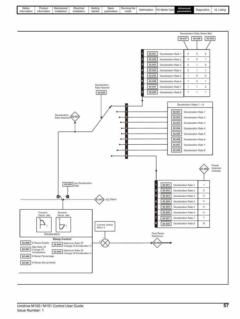
Safety information
Product information
Mechanical installation
Electrical installation
Getting started
Basic parameters
Running the motor Optimization NV Media Card Advanced
parameters Diagnostics UL Listing
02.006 S-Ramp Enable
02.007Max Rate OfChange OfAcceleration
02.040 S-Ramp Percentage
Ramp Control
N
t
N
t
Deceleration
ForwardDecel. rate
ReverseDecel. rate
+
_
Current controlMenu 4
Deceleration Rates 1 ~ 8
02.021 Deceleration Rate 1
02.022 Deceleration Rate 2
02.023 Deceleration Rate 3
02.024 Deceleration Rate 4
02.025 Deceleration Rate 5
02.026 Deceleration Rate 6
02.027 Deceleration Rate 7
02.028 Deceleration Rate 8
01.050
PresetSelectedIndicator
02.029Jog DecelerationRate
01.013 Jog Select
02.001
Post-RampReference
02.020
DecelerationRate Selector
Deceleration Rate Select Bits
02.037 02.036 02.035
02.031DecelerationRate Selected
02.041 S-Ramp Set-up Mode
02.044Maximum Rate OfChange Of Acceleration 3
02.045Maximum Rate OfChange Of Acceleration 4
02.021 Deceleration Rate 1
02.022 Deceleration Rate 2
02.023 Deceleration Rate 3
02.024 Deceleration Rate 4
02.025 Deceleration Rate 5
02.026 Deceleration Rate 6
02.027 Deceleration Rate 7
02.028 Deceleration Rate 8
02.021 Deceleration Rate 1
02.022 Deceleration Rate 2
02.023 Deceleration Rate 3
02.024 Deceleration Rate 4
02.025 Deceleration Rate 5
02.026 Deceleration Rate 6
02.027 Deceleration Rate 7
02.028 Deceleration Rate 8
3
4
1
2
7
8
5
6
Unidrive M100 / M101 Control User Guide 57Issue Number: 1

Safety information
Product information
Mechanical installation
Electrical installation
Getting started
Basic parameters
Running the motor Optimization NV Media Card Advanced
parameters Diagnostics UL Listing
ParameterRange ( ) Default ( )
TypeOL OL
02.001 Post Ramp Reference VM_SPEED_FREQ_REF Hz RO Num ND NC PT02.003 Ramp Hold Off (0) or On (1) Off (0) RW Bit US
02.004 Ramp Mode Select FASt (0), Std (1), Std.bSt (2), FSt.bSt (3) Std (1) RW Txt US
02.006 S Ramp Enable Off (0) or On (1) Off (0) RW Bit US
02.007 Max Rate Of Change OfAcceleration 0.0 to 300.0 s²/100Hz 3.1 s²/100 Hz RW Num US
02.008 Standard Ramp Voltage 0 to VM_DC_VOLTAGE_SET V
110 V drive: 375 V200 V drive: 375 V
400 V drive 50 Hz: 750 V
400 V drive 60 Hz: 775 V
575 V drive: 895 V690 V drive: 1075 V
RW Num RA US
02.009 Deceleration Fail DetectionDisable Off (0) or On (1) Off (0) RW Bit US
02.010 Acceleration Rate Selector 0 to 9 0 RW Num US02.011 Acceleration Rate 1
0.0 to VM_ACCEL_RATE s / 100 Hz 5.0 s / 100 Hz
RW Num US02.012 Acceleration Rate 2 RW Num US02.013 Acceleration Rate 3 RW Num US02.014 Acceleration Rate 4 RW Num US02.015 Acceleration Rate 5 RW Num US02.016 Acceleration Rate 6 RW Num US02.017 Acceleration Rate 7 RW Num US02.018 Acceleration Rate 8 RW Num US02.019 Jog Acceleration Rate 0.0 to VM_ACCEL_RATE s / 100 Hz 0.2 s / 100 Hz RW Num US02.020 Deceleration Rate Selector 0 to 9 0 RW Num US02.021 Deceleration Rate 1
0.0 to VM_ACCEL_RATE s / 100 Hz 10.0 s / 100 Hz
RW Num US02.022 Deceleration Rate 2 RW Num US02.023 Deceleration Rate 3 RW Num US02.024 Deceleration Rate 4 RW Num US02.025 Deceleration Rate 5 RW Num US02.026 Deceleration Rate 6 RW Num US02.027 Deceleration Rate 7 RW Num US02.028 Deceleration Rate 8 RW Num US02.029 Jog Deceleration Rate 0.0 to VM_ACCEL_RATE s / 100 Hz 0.2 s / 100 Hz RW Num US02.030 Acceleration Rate Selected 0 to 8 RO Num ND NC PT02.031 Deceleration Rate Selected 0 to 8 RO Num ND NC PT02.032 Acceleration Rate Select Bit 0 Off (0) or On (1) Off (0) RW Bit NC02.033 Acceleration Rate Select Bit 1 Off (0) or On (1) Off (0) RW Bit NC02.034 Acceleration Rate Select Bit 2 Off (0) or On (1) Off (0) RW Bit NC02.035 Deceleration Rate Select Bit 0 Off (0) or On (1) Off (0) RW Bit NC02.036 Deceleration Rate Select Bit 1 Off (0) or On (1) Off (0) RW Bit NC02.037 Deceleration Rate Select Bit 2 Off (0) or On (1) Off (0) RW Bit NC
02.039 Ramp Rate Units0 (s/100 Hz),
1 (s/Maximum Frequency), 2 (s/1000 Hz)
0 (s/100 Hz) RW Num US
02.040 S Ramp Percentage 0.0 to 50.0 % 0.0 % RW Num US02.041 S Ramp Set-up Mode 0 to 2 0 RW Num US02.042 Maximum Rate Of Change Of Acceleration 1 0.0 to 300.0 s²/100 Hz 0.0 s²/100 Hz RW Num US02.043 Maximum Rate Of Change Of Acceleration 2 0.0 to 300.0 s²/100 Hz 0.0 s²/100 Hz RW Num US02.044 Maximum Rate Of Change Of Acceleration 3 0.0 to 300.0 s²/100 Hz 0.0 s²/100 Hz RW Num US02.045 Maximum Rate Of Change Of Acceleration 4 0.0 to 300.0 s²/100 Hz 0.0 s²/100 Hz RW Num US
RW Read / Write RO Read only Num Number parameter Bit Bit parameter Txt Text string Bin Binary parameter FI FilteredND No default value NC Not copied PT Protected parameter RA Rating dependent US User save PS Power-down save DE Destination
Date Date parameter Time Time parameter
58 Unidrive M100 / M101 Control User Guide Issue Number: 1

Safety information
Product information
Mechanical installation
Electrical installation
Getting started
Basic parameters
Running the motor Optimization NV Media Card Advanced
parameters Diagnostics UL Listing
10.4 Menu 3: Frequency controlFigure 10-3 Menu 3 Open-loop logic diagram
+
_
03.00510.003
ZeroFrequency
Zero FrequencyThreshold
+
_
01.007Running At Or BelowMinimum Frequency
MinimumReference Clamp
+
_
03.00610.005
Below Set-FrequencyAt FrequencyLower Limit
+
_10.007
Above Set-FrequencyAt FrequencyUpper Limit
10.006
At Frequency
10.004
0
1
01.010
Bipolar ReferenceEnable
NOR
+0.5Hz
+
_Over SpeedTrip
1
0+20%01.006
03.008
MaximumReference
Clamp
OverFrequencyThreshold
03.008>0
mm.ppp
mm.ppp
Key
Read-write (RW)parameter
Read-only (RO)parameter
Inputterminals
Outputterminals
The parameters are all shown in their default settings
02.001
01.011
Post RampReference
Referenceon
Hard FrequencyReference
Hard FrrequencyReferenceSelect
03.023
03.022
05.001
OutputFrequency
+
+
+
+
Slipcompensation
Menu 5
Menu 2
01
01
03.007
01.003
Pre RampReference
03.009
AbsoluteAt-SpeedSelect
+
_
0
1
03.001
01.006
01.007
01.008
Maximum ReferenceClamp
Minimum ReferenceClamp
Negative ReferenceClamp Enable
03.072
Motor SpeedPercent
Final DemandReference
Unidrive M100 / M101 Control User Guide 59Issue Number: 1

Safety information
Product information
Mechanical installation
Electrical installation
Getting started
Basic parameters
Running the motor Optimization NV Media Card Advanced
parameters Diagnostics UL Listing
Figure 10-4 Menu 3 Logic diagram
ParameterRange ( ) Default ( )
TypeOL OL
03.001 Final Demand Reference VM_FREQ Hz RO Num ND NC PT FI03.005 Zero Frequency Threshold 0.00 to 20.00 Hz 2.00 Hz RW Num US03.006 At Frequency Lower Limit 0.00 to 550.00 Hz 1.00 Hz RW Num US03.007 At Frequency Upper Limit 0.00 to 550.00 Hz 1.00 Hz RW Num US03.008 Over Frequency Threshold 0.00 to 550.00 Hz 0.00 Hz RW Num US03.009 Absolute At Frequency Select Off (0) or On (1) Off (0) RW Bit US03.022 Hard Frequency Reference VM_SPEED_FREQ_REF Hz 0.00 Hz RW Num US03.023 Hard Frequency Reference Select Off (0) or On (1) Off (0) RW Bit US
03.037 Frequency Output or PWM OutputScaling (T10) 0.000 to 4.000 1.000 RW Num US
03.038 Maximum Output Frequency (T10) 1 (0), 2 (1), 5 (2), 10 (3) kHz 5 (2) kHz RW Txt US03.072 Motor Speed Percent ±150.0 % RO ND NC PT FI
RW Read / Write RO Read only Num Number parameter Bit Bit parameter Txt Text string Bin Binary parameter FI FilteredND No default value NC Not copied PT Protected parameter RA Rating dependent US User save PS Power-down save DE Destination
Date Date parameter Time Time parameter
mm.ppp
mm.ppp
Key
Read-write (RW)parameter
Read-only (RO)parameter
Inputterminals
Outputterminals
The parameters are all shown in their default settings
T 10 DigitalI/O 1
03.037
??.???
??.???
At ZeroFrequency
10.003
Any validparameter
Maximum OutputFrequency
T10 Digital I/O 01Output Select
Frequency Output orPWM Output Scaling
T10 DO1 ControlT10 DI/O Source /Destination B
T10 Digital IO1Source / Destination A
08.091
08.021
≥1
03.038
08.031
2 or 3
0 to 1
10
08.121
60 Unidrive M100 / M101 Control User Guide Issue Number: 1

Safety information
Product information
Mechanical installation
Electrical installation
Getting started
Basic parameters
Running the motor Optimization NV Media Card Advanced
parameters Diagnostics UL Listing
10.5 Menu 4: Torque and current controlFigure 10-5 Menu 4 Open loop logic diagram
04.008
10.00910.008
04.015 04.01604.018
11.032
05.007
04.005 Motoring
Regenerating
Current limits
Symmetrical
MaximumHeavy Duty
Rating
MotorRated
Current
FinalCurrent Limit
TorqueReference
Motor ThermalTime Constant 1
ThermalProtection
Mode
RatedLoad Reached
Current LimitActive
CurrentMagnitude
MagnetisingCurrent
04.020 - PercentageLoad
04.00204.020
10.01704.019
MotorProtection
Accumulator
Motor OverloadAlarm
10.039
Braking ResistorThermal
Accumulator
04.004
FinalCurrent
Reference
Torque tocurrent
conversion
05.006
OutputFrequency
FinalTorque
Reference
05.001
MotorRated
Frequency
05.001Motor map2.01
Post RampReference
OutputFrequency
02.001
Torque ModeSelector
04.011
04.013
04.014
P Gain
I Gain
Current Controller
10.009
CurrentLimit
Active
2.01
Pre RampReference
01.003
Menu 2 rampcontroller
+
_
04.025
Low FrequencyThermal
Protection Mode
Overload detection
+
+
04.001
04.017
TorqueProducing
Current
mm.ppp
mm.ppp
Key
Read-write (RW)parameter
Read-only (RO)parameter
Inputterminals
Outputterminals
The parameters are all shown in their default settings
04.003
04.026 - PercentageTorque
04.024 - User CurrentMaximum
Scaling
04.036
MotorProtection
AccumulatorPower-up Value
Unidrive M100 / M101 Control User Guide 61Issue Number: 1

Safety information
Product information
Mechanical installation
Electrical installation
Getting started
Basic parameters
Running the motor Optimization NV Media Card Advanced
parameters Diagnostics UL Listing
ParameterRange ( ) Default ( )
TypeOL OL
04.001 Current Magnitude VM_DRIVE_CURRENT A RO Num ND NC PT FI04.002 Torque Producing Current VM_DRIVE_CURRENT A RO Num ND NC PT FI04.003 Final Torque Reference VM_TORQUE_CURRENT % RO Num ND NC PT FI04.004 Final Current Reference VM_TORQUE_CURRENT % RO Num ND NC PT FI
04.005 Motoring Current Limit 0.0 to VM_MOTOR1_CURRENT_LIMIT % 165.0 % RW Num RA US
04.006 Regenerating Current Limit 0.0 to VM_MOTOR1_CURRENT_LIMIT % 165.0 % RW Num RA US
04.007 Symmetrical Current Limit 0.0 to VM_MOTOR1_CURRENT_LIMIT % 165.0 % RW Num RA US
04.008 Torque Reference VM_USER_CURRENT % 0.0 % RW Num US04.011 Torque Mode Selector 0 to 1 0 RW Num US04.013 Current Controller Kp Gain 0.00 to 4000.00 20.00 RW Num US04.014 Current Controller Ki Gain 0.000 to 600.000 40.000 RW Num US04.015 Motor Thermal Time Constant 1 1 to 3000 s 179 s RW Num US04.016 Thermal Protection Mode 0 (0) to 3 (3) 0 (0) RW Bin US04.017 Magnetising Current VM_DRIVE_CURRENT A RO Num ND NC PT FI04.018 Final Current Limit VM_TORQUE_CURRENT % RO Num ND NC PT04.019 Motor Protection Accumulator 0.0 to 100.0 % RO Num ND NC PT PS04.020 Percentage Load VM_USER_CURRENT % RO Num ND NC PT FI
04.024 User Current Maximum Scaling 0.0 to VM_TORQUE_CURRENT_UNIPOLAR % 165.0 % RW Num RA US
04.025 Low Frequency Thermal Protection Mode 0 to 1 0 RW Num US
04.026 Percentage Torque VM_USER_CURRENT % RO Num ND NC PT FI
04.036 Motor Protection AccumulatorPower-up Value Pr.dn (0), 0 (1) Pr.dn (0) RW Txt US
04.041 User Over Current Trip Level 0 to 100 % 100 % RW Num RA US
RW Read / Write RO Read only Num Number parameter Bit Bit parameter Txt Text string Bin Binary parameter FI FilteredND No default value NC Not copied PT Protected parameter RA Rating dependent US User save PS Power-down save DE Destination
Date Date parameter Time Time parameter
62 Unidrive M100 / M101 Control User Guide Issue Number: 1
Safety information
Product information
Mechanical installation
Electrical installation
Getting started
Basic parameters
Running the motor Optimization NV Media Card Advanced
parameters Diagnostics UL Listing
10.6 Menu 5: Motor controlFigure 10-6 Menu 5 Open-loop logic diagram
02.001
Post RampReference
+
+
05.010
05.011Number OfMotor Poles
05.002
OutputVoltage
05.003OutputPower (kW) 3 x V x I
Volt
L1 L2 L3
05.005
DC BusVoltage
05.009
05.007
05.008
05.006Motor RatedFrequency
Motor RatedCurrent
Motor RatedSpeed
Motor RatedVoltage
Motor RatedPower Factor
04.00204.020
04.017
04.001
CurrentMagnitude
MagnetisingCurrent
TorqueProducing
Current
PercentageLoad
Motormap
05.012
Autotune
05.014 Control Mode
05.001OutputFrequency
05.004
MotorRPM
Slip Compensation
05.018
05.019
Maximum SwitchingFrequency
High Stability SpaceVector Modulation
Hertz
05.020
05.035
Over ModulationEnable
Auto SwitchingFrequency ChangeDiasble
05.031Voltage ControllerGain
mm.ppp
mm.ppp
Key
Read-write (RW)parameter
Read-only (RO)parameter
Inputterminals
Outputterminals
The parameters are all shown in their default settings
05.032
Torque PerAmp
05.033
05.036
05.027Enable SlipCompensation
Slip CompensationLimit
Slip CompensationFilter
StatorResistance
05.015Low FrequencyVoltage Boost
05.013Dynamic V To FSelect
TransientInductance
05.024
StatorInductance
05.025
05.037
SwitchingFrequency
05.042Reverse OutputPhase Sequence
Unidrive M100 / M101 Control User Guide 63Issue Number: 1

Safety information
Product information
Mechanical installation
Electrical installation
Getting started
Basic parameters
Running the motor Optimization NV Media Card Advanced
parameters Diagnostics UL Listing
ParameterRange ( ) Default ( )
TypeOL OL
05.001 Output Frequency VM_SPEED_FREQ_REF Hz RO Num ND NC PT FI
05.002 Output Voltage 0 to VM_AC_VOLTAGE V RO Num ND NC PT FI
05.003 Output Power VM_POWER kW RO Num ND NC PT FI
05.004 Motor Rpm ±33000 rpm RO Num ND NC PT FI
05.005 D.C. Bus Voltage 0 to VM_DC_VOLTAGE V RO Num ND NC PT FI
05.006 Motor Rated Frequency 0.00 to 550.00 Hz 50 Hz: 50.00 Hz, 60 Hz: 60.00 Hz RW Num RA US
05.007 Motor Rated Current 0.00 to VM_RATED_CURRENT A Maximum Heavy Duty Rating (11.032) RW Num RA US
05.008 Motor Rated Speed 0.0 to 33000.0 rpm 50 Hz: 1500.0 rpm60 Hz: 1800.0 rpm RW Num US
05.009 Motor Rated Voltage 0 to VM_AC_VOLTAGE_SET V
110V drive: 230 V200V drive: 230 V
400V drive 50Hz: 400 V400V drive 60Hz: 460 V
575V drive: 575 V690V drive: 690 V
RW Num RA US
05.010 Motor Rated Power Factor 0.00 to 1.00 0.85 RW Num RA US
05.011 Number Of Motor Poles Auto (0) to 32 (16) Auto (0) RW Num US
05.012 Autotune 0 to 2 0 RW Num NC
05.013 Dynamic V To F Select 0 to 1 0 RW Num US
05.014 Control ModeUr.S (0), Ur (1), Fd (2),
Ur.Auto (3),Ur.I (4), SrE (5), Fd.tAP (6)
Ur.I (4) RW Txt US
05.015 Low Frequency Voltage Boost 0.0 to 25.0 % 3.0 % RW Num US
05.017 Stator Resistance 0.0000 to 99.9999 Ω 0.0000 Ω RW Num RA US
05.018 Maximum Switching Frequency0.667 (0), 1 (1), 2 (2), 3 (3), 4 (4),
6 (5), 8 (6), 12 (7), 16 (8) kHz
3 (3) kHz RW Txt RA US
05.019 High Stability Space Vector Modulation Off (0) or On (1) Off (0) RW Bit US
05.020 Over Modulation Enable Off (0) or On (1) Off (0) RW Bit US
05.024 Transient Inductance 0.000 to 500.000 mH 0.000 mH RW Num RA US
05.025 Stator Inductance 0.00 to 5000.00 mH 0.00 mH RW Num RA US
05.027 Enable Slip Compensation ±150.0 % 100.0 % RW Num US
05.031 Voltage Controller Gain 1 to 30 1 RW Num US
05.033 Slip Compensation Limit 0.00 to 10.00 Hz 10.00 Hz RW Num US
05.035 Auto-switching Frequency Change Disable 0 to 2 0 RW Num US
05.036 Slip Compensation Filter 64 (0), 128 (1), 256 (2), 512 (3) ms 128 (1) ms RW Txt US
05.037 Switching Frequency0.667 (0), 1 (1), 2 (2), 3 (3), 4 (4),
6 (5), 8 (6), 12 (7), 16 (8) kHz
RO Txt ND NC PT
05.038 Minimum Switching Frequency 0 to VM_MAX_SWITCHING_FREQUENCY kHz 0.667 (0) kHz RW Txt RA
05.040 Spin Start Boost 0.0 to 10.0 1.0 RW Num US
05.042 Reverse Output Phase Sequence Off (0) or On (1) Off (0) RW Bit US
05.059 Maximum Deadtime Compensation 0.000 to 10.000 µs RO Num NC PT US
05.060 Current At Maximum DeadtimeCompensation 0.00 to 100.00 % RO Num NC PT US
05.061 Disable Deadtime Compensation Off (0) or On (1) Off (0) RW Bit US
05.074 Boost End Voltage 0.0 to 100.0 % 50.0 % RW Num US
05.075 Boost End Frequency 0.0 to 100.0 % 50.0 % RW Num US
05.076 Second Point Voltage 0.0 to 100.0 % 55.0 % RW Num US
05.077 Second Point Frequency 0.0 to 100.0 % 55.0 % RW Num US
05.078 Third point voltage 0.0 to 100.0 % 75.0 % RW Num US
05.079 Third point frequency 0.0 to 100.0 % 75.0 % RW Num US
05.080 Low acoustic noise enable Off (0) or On (1) Off (0) RW Bit US
05.081 Change to maximum drive switchingfrequency at low output current Off (0) or On (1) Off (0) RW Bit US
05.083 Voltage Shelving Disable Off (0) or On (1) Off (0) RW Bit US
05.084 Low Frequency Slip Boost 0.0 to 100.0 % 0.0 % RW Num US05.088 Ur Mode Pre-Flux Delay 0.0 to 0.7 s 0.5 s RW Num US
RW Read / Write RO Read only Num Number parameter Bit Bit parameter Txt Text string Bin Binary parameter FI FilteredND No default value NC Not copied PT Protected parameter RA Rating dependent US User save PS Power-down save DE Destination
Date Date parameter Time Time parameter
64 Unidrive M100 / M101 Control User Guide Issue Number: 1

Safety information
Product information
Mechanical installation
Electrical installation
Getting started
Basic parameters
Running the motor Optimization NV Media Card Advanced
parameters Diagnostics UL Listing
10.7 Menu 6: Sequencer and clockFigure 10-7 Menu 6 logic diagram
06.012
Enable StopKey
01.011 Reference On
01.012 Reverse Select
01.013 Jog Select
RUN
STOP/RESET
RESET
01.049
ReferenceSelectedIndicator
Logic 1
Open loop only
06.006 InjectionBraking Level
06.007 InjectionBraking Time
06.024 Reset Energy Meter
06.021Time Between FilterChanges
06.022Filter ChangeRequired / ChangeDone
06.027Energy CostPer kWh
Clock control
Time Before FilterChange Due
Running Cost06.028
Energy Meter
Inverter enable
05.003OutputPower
Pr = 401.049
0 1
Sequencer
06.001
06.003
06.008
06.009
Stop Mode
Supply Loss Mode
Hold Zero Frequency
Catch ASpinning Motor
06.040Enable SequencerLatching
06.019 Date/TimeSelector
0123
SetPo.upRunAcc.po
06.02506.026
06.015
06.030
06.031
06.032
06.033
06.034
06.037
Jog Reverse
Run
Forward / Reverse
Run Reverse
Jog Forward
Run Forward
Drive Enable
06.035
06.036
Forward Limit Switch
06.029HardwareEnable
Menu 8
T11 digital 2
T12 digital 3
T13 digital input 4
06.039
Not Stop
1
1
0
0
0
0
0
0
0
0
06.023
Reverse Limit Switch
mm.ppp
mm.ppp
Key
Read-write (RW)parameter
Read-only (RO)parameter
Inputterminals
Outputterminals
The parameters are all shown in their default settings
06.002 Limit Switch StopMode
06.052Motor Pre-heatCurrent Magnitude
06.011Sequencer StateMachine Inputs
Mains/Phase LossDetection System
06.047Input Phase LossDetection Mode
06.048Supply LossDetection Level
06.051Hold SupplyLoss Active
10.015
SupplyLoss
06.018
06.017 Time
Day OfWeek
06.016 Date
06.020 Date FormatOutput
06.084 UTC Offset
Unidrive M100 / M101 Control User Guide 65Issue Number: 1

Safety information
Product information
Mechanical installation
Electrical installation
Getting started
Basic parameters
Running the motor Optimization NV Media Card Advanced
parameters Diagnostics UL Listing
ParameterRange ( ) Default( )
TypeOL OL
06.001 Stop Mode CoASt (0), rP (1), rP.dc I (2), dc I (3), td.dc I (4), diS (5) rP (1) RW Txt US
06.002 Limit Switch Stop Mode StoP (0) or rP (1), rP (1) RW Txt US
06.003 Supply Loss Mode diS (0), rP.StoP (1),ridE.th (2) diS (0) RW Txt US
06.004 Start/Stop Logic Select 0 to 6 50 Hz: 0, 60 Hz: 4 RW Num US06.006 Injection Braking Level 0.0 to 150.0 % 100.0 % RW Num RA US06.007 Injection Braking Time 0.0 to 100.0 s 1.0 s RW Num US06.008 Hold Zero Frequency Off (0) or On (1) Off (0) RW Bit US
06.009 Catch A Spinning Motor diS (0), EnAbLE (1), Fr.OnLy (2), rv.OnLy (3) diS (0) RW Txt US
06.010 Enable Conditions 0 to 4087 RO Bin ND NC PT06.011 Sequencer State Machine Inputs 0 to 127 RO Bin ND NC PT06.012 Enable Stop Key Off (0) or On (1) Off (0) RW Bit US06.014 Disable Auto Reset On Enable Off (0) or On (1) Off (0) RW Bit US06.015 Drive Enable Off (0) or On (1) On (1) RW Bit NC US06.016 Date 00-00-00 to 31-12-99 RW Date ND NC PT06.017 Time 00:00:00 to 23:59:59 RW Time ND NC PT
06.018 Day Of Week Sun (0), Non (1), tuE (2), UEd (3), thu (4), Fri (5), SAt (6) RO Txt ND NC PT
06.019 Date/Time Selector SEt (0), Po.uP (1), run (2), Acc.Po (3) Po.uP (1) RW Txt US
06.020 Date Format Std (0), US (1) Std (0) RW Txt US06.021 Time Between Filter Changes 0 to 30000 Hours 0 Hours RW Num US
06.022 Filter Change Required /Change Done Off (0) or On (1) RW Bit ND NC
06.023 Time Before Filter Change Due 0 to 30000 Hours RO Num ND NC PT PS06.024 Reset Energy Meter Off (0) or On (1) Off (0) RW Bit06.025 Energy Meter: MWh ±999.9 MWh RO Num ND NC PT PS06.026 Energy Meter: kWh ±99.99 kWh RO Num ND NC PT PS06.027 Energy Cost Per kWh 0.0 to 600.0 0.0 RW Num US06.028 Running Cost ±32000 RO Num ND NC PT06.029 Hardware Enable Off (0) or On (1) RO Bit NC06.030 Run Forward Off (0) or On (1) Off (0) RW Bit NC06.031 Jog Forward Off (0) or On (1) Off (0) RW Bit NC06.032 Run Reverse Off (0) or On (1) Off (0) RW Bit NC06.033 Forward/Reverse Off (0) or On (1) Off (0) RW Bit NC06.034 Run Off (0) or On (1) Off (0) RW Bit NC06.035 Forward Limit Switch Off (0) or On (1) Off (0) RW Bit NC06.036 Reverse Limit Switch Off (0) or On (1) Off (0) RW Bit NC06.037 Jog Reverse Off (0) or On (1) Off (0) RW Bit NC06.038 User Enable Off (0) or On (1) Off (0) RW Bit NC06.039 Not Stop Off (0) or On (1) Off (0) RW Bit NC06.040 Enable Sequencer Latching Off (0) or On (1) Off (0) RW Bit US06.041 Drive Event Flags 0 to 3 0 RW Bin NC06.045 Cooling Fan control 0 to 5 2 RW Num US06.046 Supply Loss Hold Disable Off (0) or On (1) Off (0) RW Bit US
06.047 Input Phase Loss DetectionMode FuLL (0), rIPPLE (1), diS (2) FuLL (0) RW Txt US
06.048 Supply Loss Detection Level 0 to VM_SUPPLY_LOSS_LEVEL V110 V drive: 205 V200 V drive: 205 V400 V drive: 410 V
RW Num RA US
06.051 Hold Supply Loss Active Off (0) or On (1) Off (0) RW Bit NC
06.052 Motor Pre-heatCurrent Magnitude 0 to 100 % 0 % RW Num US
06.058 Output Phase Loss DetectionTime 0.5 (0) to 4 (3) s 0.5 (0) s RW Txt US
06.059 Output Phase Loss DetectionEnable Off (0) or On (1) Off (0) RW Bit US
06.060 Standby Mode Enable Off (0) or On (1) Off (0) RW Bit US
66 Unidrive M100 / M101 Control User Guide Issue Number: 1
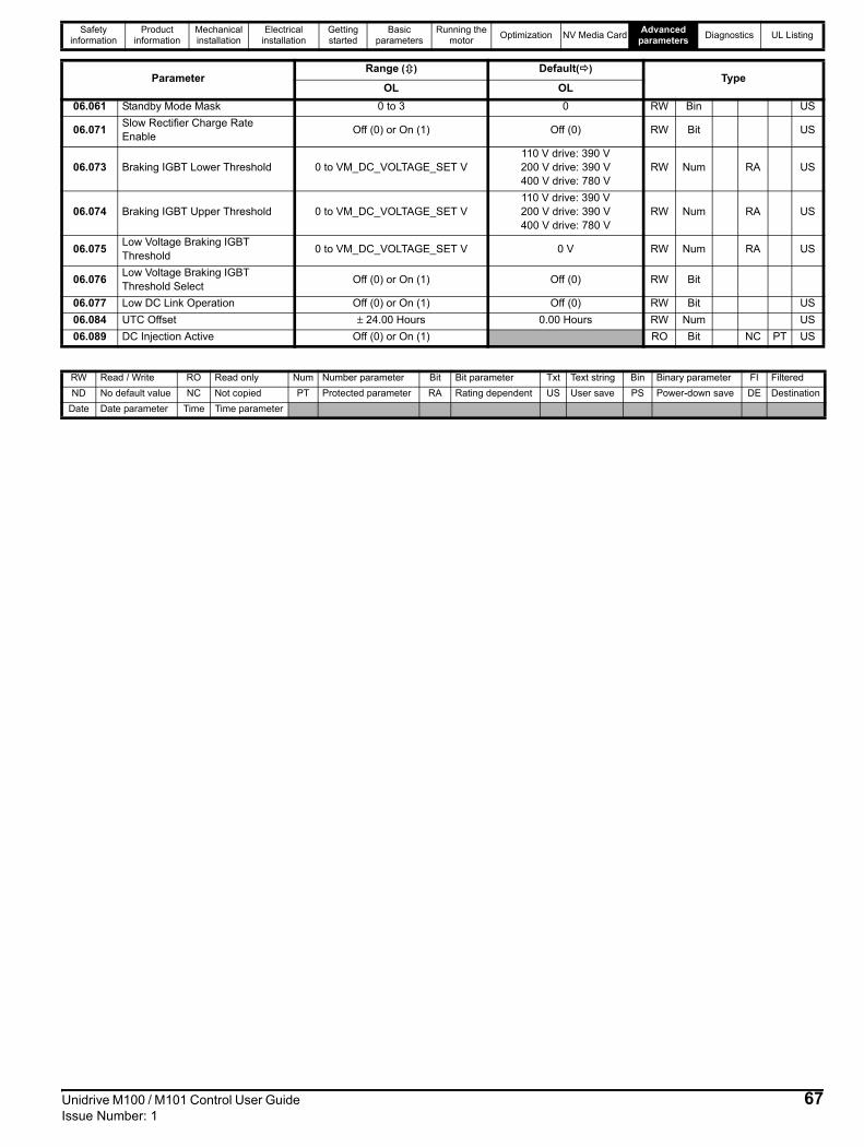
Safety information
Product information
Mechanical installation
Electrical installation
Getting started
Basic parameters
Running the motor Optimization NV Media Card Advanced
parameters Diagnostics UL Listing
06.061 Standby Mode Mask 0 to 3 0 RW Bin US
06.071 Slow Rectifier Charge RateEnable Off (0) or On (1) Off (0) RW Bit US
06.073 Braking IGBT Lower Threshold 0 to VM_DC_VOLTAGE_SET V110 V drive: 390 V200 V drive: 390 V400 V drive: 780 V
RW Num RA US
06.074 Braking IGBT Upper Threshold 0 to VM_DC_VOLTAGE_SET V110 V drive: 390 V200 V drive: 390 V400 V drive: 780 V
RW Num RA US
06.075 Low Voltage Braking IGBTThreshold 0 to VM_DC_VOLTAGE_SET V 0 V RW Num RA US
06.076 Low Voltage Braking IGBTThreshold Select Off (0) or On (1) Off (0) RW Bit
06.077 Low DC Link Operation Off (0) or On (1) Off (0) RW Bit US06.084 UTC Offset ± 24.00 Hours 0.00 Hours RW Num US06.089 DC Injection Active Off (0) or On (1) RO Bit NC PT US
RW Read / Write RO Read only Num Number parameter Bit Bit parameter Txt Text string Bin Binary parameter FI FilteredND No default value NC Not copied PT Protected parameter RA Rating dependent US User save PS Power-down save DE Destination
Date Date parameter Time Time parameter
ParameterRange ( ) Default( )
TypeOL OL
Unidrive M100 / M101 Control User Guide 67Issue Number: 1

Safety information
Product information
Mechanical installation
Electrical installation
Getting started
Basic parameters
Running the motor Optimization NV Media Card Advanced
parameters Diagnostics UL Listing
10.8 Menu 7: Analog I/OFigure 10-8 Menu 7 logic diagram
ParameterRange ( ) Default( )
TypeOL OL
07.001 Analog Input 1 (T2) ±100.00 % RO Num ND NC PT FI07.004 Stack Temperature ±250 °C RO Num ND NC PT07.005 Auxiliary Temperature ±250 °C RO Num ND NC PT
07.007 Analog Input 1 Mode (T2)
4-20.S (-6), 20-4.S (-5), 4-20.L (-4), 20-4.L (-3),
4-20.H (-2), 20-4.H (-1), 0-20 (0), 20-0 (1), 4-20.tr (2), 20-4.tr (3),
4-20 (4), 20-4 (5), VoLt (6)
VoLt (6) RW Txt US
07.008 Analog Input 1 Scaling (T2) 0.000 to 10.000 1.000 RW Num US07.009 Analog Input 1 Invert (T2) Off (0) or On (1) Off (0) RW Bit US07.010 Analog Input 1 Destination A (T2) 0.000 to 30.999 1.036 RW Num DE PT US07.026 Analog Input 1 Preset on Current Loss (T2) 4.00 to 20.00 4.00 RW Num US07.028 Analog Input 1 Current Loop Loss (T2) Off (0) or On (1) RO Bit ND NC PT07.030 Analog Input 1 Offset (T2) ±100.00 % 0.00 % RW Num US07.034 Inverter Temperature ±250 °C RO Num ND NC PT
07.035 Percentage Of d.c. Link Thermal TripLevel 0 to 100 % RO Num ND NC PT
07.036 Percentage Of Drive Thermal Trip Level 0 to 100 % RO Num ND NC PT07.037 Temperature Nearest To Trip Level 0 to 29999 RO Num ND NC PT07.051 Analog Input 1 Control (T2) 0 to 5 0 RW Num US07.061 Analog Input 1 Minimum Reference (T2) 0.00 to 100.00 % 0.00 % RW Num US
07.062 Analog Input 1 At MinimumReference (T2) ±100.00 % 0.00 % RW Num US
07.063 Analog Input 1 Maximum Reference (T2) 0.00 to 100.00 % 100.00 % RW Num US07.064 Analog Input 1 At Maximum Reference (T2) ±100.00 % 100.00 % RW Num US07.090 Analog Input 1 Destination B (T2) 0.000 to 30.999 RO Num DE PT US
mm.ppp
mm.ppp
Key
Read-write (RW)parameter
Read-only (RO)parameter
Inputterminals
Outputterminals
The parameters are all shown in their default settings
07.007 07.008
AnalogInput 1Scaling
??.???
Anyunprotectedvariableparameter
??.???x(-1)
Analog Input 1
07.009 AnalogInput 1 Invert
07.028
AnalogInput 1 Current
Loop Loss
07.001
AnalogInput 1
01.036
AnalogRef. 1
++
07.030
Analog Input1 Offset
T2 Analog Input1 Mode
07.063 07.064
T2 Analog Input 1Maximum Reference
T2 Analog Input 1At MaximumReference
07.062
07.061T2 Analog Input 1Minimum Reference
T2 Analog Input 1At Minimum Reference
Analog Input 1Destination A
Analog Input1 Control
Analog Input 1Destination B 07.051
07.010
≥107.090
RW Read / Write RO Read only Num Number parameter Bit Bit parameter Txt Text string Bin Binary parameter FI FilteredND No default value NC Not copied PT Protected parameter RA Rating dependent US User save PS Power-down save DE Destination
Date Date parameter Time Time parameter
68 Unidrive M100 / M101 Control User Guide Issue Number: 1

Safety information
Product information
Mechanical installation
Electrical installation
Getting started
Basic parameters
Running the motor Optimization NV Media Card Advanced
parameters Diagnostics UL Listing
Unidrive M100 / M101 Control User Guide 69Issue Number: 1

Safety information
Product information
Mechanical installation
Electrical installation
Getting started
Basic parameters
Running the motor Optimization NV Media Card Advanced
parameters Diagnostics UL Listing
10.9 Menu 8: Digital I/OFigure 10-9 Menu 8 logic diagram
T10 Digital I/O01 Output Mode
08.031
??.???
??.???
Anyunprotectedbit parameter
??.???
??.???
Any bitparameter
x(-1)
x(-1)
08.011 T10 DigitalI/O 1 Invert
T10 Digital I/O1 State
08.001 10.003
At ZeroFrequency
T10 Digital I/O 1
mm.ppp
mm.ppp
Key
Read-write (RW)parameter
Read-only (RO)parameter
Inputterminals
Outputterminals
The parameters are all shown in their default settings
Frequency orPWM output
0 or 1
2 or 3
T10 Digital I/O 1source / destination A
08.021
T10 DI/O 01 Source/ Destination B
T11 Digital input 2
08.002T11 Digitalinput 2 state
T11 Digitalinput 2 invert
??.???
Any unprotected
Userenable
bit parameter
T11 DI 02Destination B
T11 DI 2 Control
T11 Digital Input 02Destination A
??.???x(-1)
06.038
08.082
08.02208.012
≥1
≥1
T10 DI1 Control T10 DO1 Control
08.09108.081
08.121
08.122
70 Unidrive M100 / M101 Control User Guide Issue Number: 1

Safety information
Product information
Mechanical installation
Electrical installation
Getting started
Basic parameters
Running the motor Optimization NV Media Card Advanced
parameters Diagnostics UL Listing
??.???
Any unprotectedbit parameter
??.???
08.013
T12 DigitalInput 3 InvertT12 Digital
Input 3 State08.003
06.030
Run forward
T12 Digital Input 3
x(-1)
T12 DI3 Control 08.083
08.023
T12 DI 03Destination B
T12 Digital input3 destination A
??.???
Any unprotectedbit parameter
??.???
08.014
T13 DigitalInput 4 InvertT13 Digital
Input 4 State08.004
06.032
Run reverse
T13 Digital Input 4
x(-1)
T13 DI4 Control
08.084
08.024
T13 DI 04Destination B
T13 Digital input4 destination A
08.123
08.124
Unidrive M100 / M101 Control User Guide 71Issue Number: 1

Safety information
Product information
Mechanical installation
Electrical installation
Getting started
Basic parameters
Running the motor Optimization NV Media Card Advanced
parameters Diagnostics UL Listing
Figure 10-10 Menu 8 logic (relay)
08.008
Relay 1Output State
Relay 1Invert
0V
x(-1)
08.018
??.???
Any bitparameter
Relay 1source B
Relay 1control
Relay 1 OutputSource A
??.???
10.001Drive OK
08.128
08.098
08.028
72 Unidrive M100 / M101 Control User Guide Issue Number: 1

Safety information
Product information
Mechanical installation
Electrical installation
Getting started
Basic parameters
Running the motor Optimization NV Media Card Advanced
parameters Diagnostics UL Listing
ParameterRange ( ) Default ( )
TypeOL OL
08.001 Digital I/O 1 State (T10) Off (0) or On (1) RO Bit ND NC PT08.002 Digital Input 2 State(T11) Off (0) or On (1) RO Bit ND NC PT08.003 Digital Input 3 State (T12) Off (0) or On (1) RO Bit ND NC PT08.004 Digital Input 4 State (T13) Off (0) or On (1) RO Bit ND NC PT08.008 Relay 1 Output State Off (0) or On (1) RO Bit ND NC PT08.011 Digital I/O 1 Invert (T10) Not.Inv (0), InvErt (1) Not.Inv (0) RW Txt US08.012 Digital Input 2 Invert (T11) Not.Inv (0), InvErt (1) Not.Inv (0) RW Txt US08.013 Digital Input 3 Invert (T12) Not.Inv (0), InvErt (1) Not.Inv (0) RW Txt US08.014 Digital Input 4 Invert (T13) Not.Inv (0), InvErt (1) Not.Inv (0) RW Txt US08.018 Relay 1 Invert Not.Inv (0), InvErt (1) Not.Inv (0) RW Txt US08.020 Digital I/O Read Word 0 to 2048 RO Num ND NC PT08.021 Digital IO1 Source / Destination A (T10) 0.000 to 30.999 10.003 RW Num DE PT US
08.022 Digital Input 2 Destination A (T11) 0.000 to 30.999 50 Hz: 6.03860 Hz: 6.039 RW Num DE PT US
08.023 Digital Input 03 Destination A (T12) 0.000 to 30.999 50 Hz: 6.03060 Hz: 6.034 RW Num DE PT US
08.024 Digital Input 04 Destination A (T13) 0.000 to 30.999 50 Hz: 6.03260 Hz: 6.031 RW Num DE PT US
08.028 Relay 1 Output Source A 0.000 to 30.999 10.001 RW Num PT US
08.031 Digital I/O 01 Output Mode (T10) InPut (0), OutPut (1), Fr (2), PuLSE (3) OutPut (1) RW Txt US
08.043 24 V Supply Input State Off (0) or On (1) RO Bit ND NC PT08.053 24 V Supply Invert Not.Inv (0), InvErt (1) Not.Inv (0) RW Txt US08.063 24 V Supply Input Destination 0.000 to 30.999 0.000 RW Num DE PT US08.081 DI1 Control (T10) 0 to 21 0 RW Num US08.082 DI2 Control (T11) 0 to 21 0 RW Num US08.083 DI3 Control (T12) 0 to 21 0 RW Num US08.084 DI4 Control (T13) 0 to 21 0 RW Num US08.091 DO1 Control 0 to 20 0 RW Num US08.098 Relay 1 Control 0 to 20 0 RW Num US08.121 DI/O 01 Source / Destination B (T10) 0.000 to 30.999 RO Num DE PT US08.122 Digital Input 2 Destination B (T11) 0.000 to 30.999 RO Num DE PT US08.123 DI 03 Destination B (T12) 0.000 to 30.999 RO Num DE PT US08.124 DI 04 Destination B (T13) 0.000 to 30.999 RO Num DE PT US08.128 Relay 01 Source B 0.000 to 30.999 0.000 RW Num PT US
RW Read / Write RO Read only Num Number parameter Bit Bit parameter Txt Text string Bin Binary parameter FI FilteredND No default value NC Not copied PT Protected parameter RA Rating dependent US User save PS Power-down save DE Destination
Date Date parameter Time Time parameter
Unidrive M100 / M101 Control User Guide 73Issue Number: 1

Safety information
Product information
Mechanical installation
Electrical installation
Getting started
Basic parameters
Running the motor Optimization NV Media Card Advanced
parameters Diagnostics UL Listing
10.10 Menu 10: Status and trips
ParameterRange ( ) Default ( )
TypeOL OL
10.001 Drive OK Off (0) or On (1) RO Bit ND NC PT10.002 Drive Active Off (0) or On (1) RO Bit ND NC PT10.003 Zero Frequency Off (0) or On (1) RO Bit ND NC PT
10.004 Running At or Below MinimumFrequency Off (0) or On (1) RO Bit ND NC PT
10.005 Below Set Frequency Off (0) or On (1) RO Bit ND NC PT10.006 At Frequency Off (0) or On (1) RO Bit ND NC PT10.007 Above Set Frequency Off (0) or On (1) RO Bit ND NC PT10.008 Rated Load Reached Off (0) or On (1) RO Bit ND NC PT10.009 Current Limit Active Off (0) or On (1) RO Bit ND NC PT10.010 Regenerating Off (0) or On (1) RO Bit ND NC PT10.011 Braking IGBT Active Off (0) or On (1) RO Bit ND NC PT10.012 Braking Resistor Alarm Off (0) or On (1) RO Bit ND NC PT10.013 Reverse Direction Commanded Off (0) or On (1) RO Bit ND NC PT10.014 Reverse Direction Running Off (0) or On (1) RO Bit ND NC PT10.015 Supply Loss Off (0) or On (1) RO Bit ND NC PT10.016 Under Voltage Active Off (0) or On (1) RO Bit ND NC PT10.017 Motor Overload Alarm Off (0) or On (1) RO Bit ND NC PT10.018 Drive Over-temperature Alarm Off (0) or On (1) RO Bit ND NC PT10.019 Drive Warning Off (0) or On (1) RO Bit ND NC PT10.020 Trip 0 0 to 255 RO Txt ND NC PT PS10.021 Trip 1 0 to 255 RO Txt ND NC PT PS10.022 Trip 2 0 to 255 RO Txt ND NC PT PS10.023 Trip 3 0 to 255 RO Txt ND NC PT PS10.024 Trip 4 0 to 255 RO Txt ND NC PT PS10.025 Trip 5 0 to 255 RO Txt ND NC PT PS10.026 Trip 6 0 to 255 RO Txt ND NC PT PS10.027 Trip 7 0 to 255 RO Txt ND NC PT PS10.028 Trip 8 0 to 255 RO Txt ND NC PT PS10.029 Trip 9 0 to 255 RO Txt ND NC PT PS10.030 Braking Resistor Rated Power 0.0 to 99999.9 kW 0.0 kW RW Num US
10.031 Braking Resistor Thermal TimeConstant 0.00 to 1500.00 s 0.00 s RW Num US
10.032 External Trip Off (0) or On (1) Off (0) RW Bit NC10.033 Drive Reset Off (0) or On (1) Off (0) RW Bit NC
10.034 Number Of Auto-reset Attempts NonE (0), 1 (1), 2 (2), 3 (3), 4 (4), 5 (5),inF (6) NonE (0) RW Txt US
10.035 Auto-reset Delay 0.0 to 600.0 s 1.0 s RW Num US10.036 Auto-reset Hold Drive Healthy Off (0) or On (1) Off (0) RW Bit US10.037 Action On Trip Detection 0 to 31 0 RW Num US10.038 User Trip 0 to 255 RW Num ND NC
10.039 Braking Resistor ThermalAccumulator 0.0 to 100.0 % RO Num ND NC PT
10.040 Status Word 0 to 32767 RO Num ND NC PT10.041 Trip 0 Date 00-00-00 to 31-12-99 RO Date ND NC PT PS10.042 Trip 0 Time 00:00:00 to 23:59:59 RO Time ND NC PT PS10.043 Trip 1 Date 00-00-00 to 31-12-99 RO Date ND NC PT PS10.044 Trip 1 Time 00:00:00 to 23:59:59 RO Time ND NC PT PS10.045 Trip 2 Date 00-00-00 to 31-12-99 RO Date ND NC PT PS10.046 Trip 2 Time 00:00:00 to 23:59:59 RO Time ND NC PT PS10.047 Trip 3 Date 00-00-00 to 31-12-99 RO Date ND NC PT PS10.048 Trip 3 Time 00:00:00 to 23:59:59 RO Time ND NC PT PS10.049 Trip 4 Date 00-00-00 to 31-12-99 RO Date ND NC PT PS10.050 Trip 4 Time 00:00:00 to 23:59:59 RO Time ND NC PT PS10.051 Trip 5 Date 00-00-00 to 31-12-99 RO Date ND NC PT PS
74 Unidrive M100 / M101 Control User Guide Issue Number: 1

Safety information
Product information
Mechanical installation
Electrical installation
Getting started
Basic parameters
Running the motor Optimization NV Media Card Advanced
parameters Diagnostics UL Listing
10.052 Trip 5 Time 00:00:00 to 23:59:59 RO Time ND NC PT PS10.053 Trip 6 Date 00-00-00 to 31-12-99 RO Date ND NC PT PS10.054 Trip 6 Time 00:00:00 to 23:59:59 RO Time ND NC PT PS10.055 Trip 7 Date 00-00-00 to 31-12-99 RO Date ND NC PT PS10.056 Trip 7 Time 00:00:00 to 23:59:59 RO Time ND NC PT PS10.057 Trip 8 Date 00-00-00 to 31-12-99 RO Date ND NC PT PS10.058 Trip 8 Time 00:00:00 to 23:59:59 RO Time ND NC PT PS10.059 Trip 9 Date 00-00-00 to 31-12-99 RO Date ND NC PT PS10.060 Trip 9 Time 00:00:00 to 23:59:59 RO Time ND NC PT PS10.061 Braking Resistor Resistance 0.00 to 10000.00 Ω 0.00 Ω RW Num US10.065 Autotune Active Off (0) or On (1) RO Bit ND NC PT10.066 Limit Switch Active Off (0) or On (1) RO Bit ND NC PT
10.068 Hold Drive Healthy On Under Voltage Off (0) or On (1) Off (0) RW Bit US
10.069 Additional Status Bits 0 to 2047 RO Num ND NC PT10.070 Trip 0 Sub-trip Number 0 to 65535 RO Num ND NC PT PS10.071 Trip 1 Sub-trip Number 0 to 65535 RO Num ND NC PT PS10.072 Trip 2 Sub-trip Number 0 to 65535 RO Num ND NC PT PS10.073 Trip 3 Sub-trip Number 0 to 65535 RO Num ND NC PT PS10.074 Trip 4 Sub-trip Number 0 to 65535 RO Num ND NC PT PS10.075 Trip 5 Sub-trip Number 0 to 65535 RO Num ND NC PT PS10.076 Trip 6 Sub-trip Number 0 to 65535 RO Num ND NC PT PS10.077 Trip 7 Sub-trip Number 0 to 65535 RO Num ND NC PT PS10.078 Trip 8 Sub-trip Number 0 to 65535 RO Num ND NC PT PS10.079 Trip 9 Sub-trip Number 0 to 65535 RO Num ND NC PT PS10.080 Stop Motor Off (0) or On (1) RO Bit ND NC PT10.081 Phase Loss Off (0) or On (1) RO Bit ND NC PT10.090 Drive Ready Off (0) or On (1) RO Bit ND NC PT
10.101 Drive Status
Inh (0), rdy (1), StoP (2), ScAn (3), rES (4), S.LoSS (5), rES (6), dc.inJ (7), rES (8),
Error (9), ActivE (10), rES (11), rES (12), rES (13), HEAt (14), UU (15)
RO Txt ND NC PT
10.102 Trip Reset Source 0 to 1023 RO Num ND NC PT PS10.103 Trip Time Identifier -2147483648 to 2147483647 ms RO Num ND NC PT
10.104 Active Alarm
NonE (0), br.rES (1), OV.Ld (2), rES (3), d.OV.Ld (4), tuning (5), LS (6), rES (7),
rES (8), rES (9), rES (10), rES (11), rES(12), Lo.AC (13), I.AC.Lt (14),
24.LoSt (15)
RO Txt ND NC PT
10.106 Potential Drive DamageConditions 0 to 3 RO Bin ND NC PT PS
10.107 Low AC Alarm Off (0) or On (1) RO Bit ND NC PT10.108 Reversed cooling fan detected Off (0) or On (1) RO Bit ND PT
RW Read / Write RO Read only Num Number parameter Bit Bit parameter Txt Text string Bin Binary parameter FI FilteredND No default value NC Not copied PT Protected parameter RA Rating dependent US User save PS Power-down save DE Destination
Date Date parameter Time Time parameter
ParameterRange ( ) Default ( )
TypeOL OL
Unidrive M100 / M101 Control User Guide 75Issue Number: 1

Safety information
Product information
Mechanical installation
Electrical installation
Getting started
Basic parameters
Running the motor Optimization NV Media Card Advanced
parameters Diagnostics UL Listing
10.11 Menu 11: General drive set-upParameter
Range ( ) Default ( )Type
OL OL11.018 Status Mode Parameter 1 0.000 to 30.999 2.001 RW Num PT US11.019 Status Mode Parameter 2 0.000 to 30.999 4.020 RW Num PT US11.021 Customer Defined Scaling 0.000 to 10.000 1.000 RW Num US11.022 Parameter Displayed At Power-up 0.000 to 0.080 0.010 RW Num PT US11.028 Drive Derivative 0 to 255 RO Num ND NC PT11.029 Software Version 00.00.00 to 99.99.99 RO Ver ND NC PT11.030 User Security Code 0 to 9999 RW Num ND NC PT US11.031 User Drive Mode OPEn.LP (1) RW Txt ND NC PT US11.032 Maximum Heavy Duty Rating 0.00 to 9999.99 A RO Num ND NC PT11.033 Drive Rated Voltage 110V (0), 200V (1), 400V (2), RO Txt ND NC PT
11.034 Drive ConfigurationAV (0), AI (1), AV.Pr (2), AI.Pr (3), PrESEt (4), PAd (5), PAd.rEF (6),
torquE (8)AV (0)* RW Txt PT US
11.035 Power Software Version 00.00.00 to 99.99.99 RO Ver ND NC PT
11.036 NV Media Card File Previously Loaded 0 to 999 0 RO Num NC PT
11.037 NV Media Card File Number 0 to 999 0 RW Num11.038 NV Media Card File Type NonE (0), OPEn.LP (1) RO Txt ND NC PT11.039 NV Media Card File Version 0 to 9999 RO Num ND NC PT
11.042 Parameter Cloning NonE (0), rEAd (1), Prog (2), Auto (3), boot (4) NonE (0) RW Txt NC US
11.043 Load Defaults NonE (0), Std (1), US (2) NonE (0) RW Txt NC
11.044 User Security Status LEVEL.0 (0), ALL (1), r.onLy.0 (2), r.onLy.A (3), StAtUS (4), no.Acc (5) LEVEL.0 (0) RW Txt ND PT
11.046 Defaults Previously Loaded 0 to 2000 RO Num ND NC PT US11.052 Serial Number LS 0 to 999999 RO Num ND NC PT11.053 Serial Number MS 0 to 999999 RO Num ND NC PT11.054 Drive Date Code 0 to 9999 RO Num ND NC PT11.060 Maximum Rated Current 0.000 to 999.999 A RO Num ND NC PT11.061 Full Scale Current Kc 0.000 to 999.999 A RO Num ND NC PT11.063 Product Type 0 to 255 RO Num ND NC PT11.064 Product Identifier Characters 100 / 101 RO Chr ND NC PT11.065 Frame size and voltage code 0 to 999 RO Num ND NC PT11.066 Power Stage Identifier 0 to 255 RO Num ND NC PT11.067 Control Board Identifier 0 to 255 RO Num ND NC PT11.068 Drive current rating 0 to 32767 RO Num ND NC PT11.070 Core Parameter Database Version 0.00 to 99.99 RO Num ND NC PT11.072 NV Media Card Create Special File 0 to 1 0 RW Num NC11.073 NV Media Card Type NonE(0), rES(1), Sd.CArd(2) RO Num ND NC PT11.075 NV Media Card Read-only Flag Off (0) or On (1) RO Bit ND NC PT
11.076 NV Media Card WarningSuppression Flag Off (0) or On (1) RO Bit ND NC PT
11.077 NV Media Card File Required Version 0 to 9999 RW Num ND NC PT
11.079 Drive Name Characters 1-4 (-2147483648) to (2147483647) - - - - (757935405) RW Chr PT US
11.080 Drive Name Characters 5-8 (-2147483648) to (2147483647) - - - - (757935405) RW Chr PT US
11.081 Drive Name Characters 9-12 (-2147483648) to (2147483647) - - - - (757935405) RW Chr PT US
11.082 Drive Name Characters 13-16 (-2147483648) to (2147483647) - - - - (757935405) RW Chr PT US
11.084 Drive Mode OPEn.LP (1) RO Txt ND NC PT
11.085 Security Status NonE (0), r.onLy.A (1), StAtUS (2), no.Acc (3) RO Txt ND NC PT PS
11.086 Menu Access Status LEVEL.0 (0), ALL (1) RO Txt ND NC PT PS
11.091 Additional Identifier Characters 1 (-2147483648) to (2147483647) RO Chr ND NC PT
11.092 Additional Identifier Characters 2 (-2147483648) to (2147483647) RO Chr ND NC PT
76 Unidrive M100 / M101 Control User Guide Issue Number: 1

Safety information
Product information
Mechanical installation
Electrical installation
Getting started
Basic parameters
Running the motor Optimization NV Media Card Advanced
parameters Diagnostics UL Listing
* With Unidrive M101, the default is PAd (5).
11.093 Additional Identifier Characters 3 (-2147483648) to (2147483647) RO Chr ND NC PT
11.094 Disable String Mode Off (0) or On (1) Off (0) RW Bit PT US11.097 AI ID Code NonE (0), Sd.CArd (1) RO Txt ND NC PT11.098 24V Alarm Loss Enable Off (0) or On (1) Off (0) RW Bit US
ParameterRange ( ) Default ( )
TypeOL OL
RW Read / Write RO Read only Num Number parameter Bit Bit parameter Txt Text string Bin Binary parameter FI FilteredND No default value NC Not copied PT Protected parameter RA Rating dependent US User save PS Power-down save DE Destination
Date Date parameter Time Time parameter
Unidrive M100 / M101 Control User Guide 77Issue Number: 1

Safety information
Product information
Mechanical installation
Electrical installation
Getting started
Basic parameters
Running the motor Optimization NV Media Card Advanced
parameters Diagnostics UL Listing
10.12 Menu 22: Additional Menu 0 set-up
ParameterRange( ) Default( )
TypeOL OL
22.001 Parameter 00.001 Set-up 0.000 to 30.999 1.007 RW Num PT US22.002 Parameter 00.002 Set-up 0.000 to 30.999 1.006 RW Num PT US22.003 Parameter 00.003 Set-up 0.000 to 30.999 2.011 RW Num PT US22.004 Parameter 00.004 Set-up 0.000 to 30.999 2.021 RW Num PT US22.005 Parameter 00.005 Set-up 0.000 to 30.999 11.034 RW Num PT US22.006 Parameter 00.006 Set-up 0.000 to 30.999 5.007 RW Num PT US22.007 Parameter 00.007 Set-up 0.000 to 30.999 5.008 RW Num PT US22.008 Parameter 00.008 Set-up 0.000 to 30.999 5.009 RW Num PT US22.009 Parameter 00.009 Set-up 0.000 to 30.999 5.010 RW Num PT US22.010 Parameter 00.010 Set-up 0.000 to 30.999 11.044 RW Num PT US22.011 Parameter 00.011 Set-up 0.000 to 30.999 0.000 RW Num PT US22.012 Parameter 00.012 Set-up 0.000 to 30.999 0.000 RW Num PT US22.013 Parameter 00.013 Set-up 0.000 to 30.999 0.000 RW Num PT US22.014 Parameter 00.014 Set-up 0.000 to 30.999 0.000 RW Num PT US22.015 Parameter 00.015 Set-up 0.000 to 30.999 1.005 RW Num PT US22.016 Parameter 00.016 Set-up 0.000 to 30.999 7.007 RW Num PT US22.017 Parameter 00.017 Set-up 0.000 to 30.999 1.010 RW Num PT US22.018 Parameter 00.018 Set-up 0.000 to 30.999 1.021 RW Num PT US22.019 Parameter 00.019 Set-up 0.000 to 30.999 0.000 RW Num PT US22.020 Parameter 00.020 Set-up 0.000 to 30.999 0.000 RW Num PT US22.021 Parameter 00.021 Set-up 0.000 to 30.999 0.000 RW Num PT US22.022 Parameter 00.022 Set-up 0.000 to 30.999 0.000 RW Num PT US22.023 Parameter 00.023 Set-up 0.000 to 30.999 0.000 RW Num PT US22.024 Parameter 00.024 Set-up 0.000 to 30.999 0.000 RW Num PT US22.025 Parameter 00.025 Set-up 0.000 to 30.999 11.030 RW Num PT US22.026 Parameter 00.026 Set-up 0.000 to 30.999 0.000 RW Num PT US22.027 Parameter 00.027 Set-up 0.000 to 30.999 1.051 RW Num PT US22.028 Parameter 00.028 Set-up 0.000 to 30.999 2.004 RW Num PT US22.029 Parameter 00.029 Set-up 0.000 to 30.999 0.000 RW Num PT US22.030 Parameter 00.030 Set-up 0.000 to 30.999 11.042 RW Num PT US22.031 Parameter 00.031 Set-up 0.000 to 30.999 6.001 RW Num PT US22.032 Parameter 00.032 Set-up 0.000 to 30.999 5.013 RW Num PT US22.033 Parameter 00.033 Set-up 0.000 to 30.999 6.009 RW Num PT US22.034 Parameter 00.034 Set-up 0.000 to 30.999 0.000 RW Num PT US22.035 Parameter 00.035 Set-up 0.000 to 30.999 8.091 RW Num PT US22.036 Parameter 00.036 Set-up 0.000 to 30.999 0.000 RW Num PT US22.037 Parameter 00.037 Set-up 0.000 to 30.999 5.018 RW Num PT US22.038 Parameter 00.038 Set-up 0.000 to 30.999 5.012 RW Num PT US22.039 Parameter 00.039 Set-up 0.000 to 30.999 5.006 RW Num PT US22.040 Parameter 00.040 Set-up 0.000 to 30.999 5.011 RW Num PT US22.041 Parameter 00.041 Set-up 0.000 to 30.999 5.014 RW Num PT US22.042 Parameter 00.042 Set-up 0.000 to 30.999 5.015 RW Num PT US22.043 Parameter 00.043 Set-up 0.000 to 30.999 0.000 RW Num PT US22.044 Parameter 00.044 Set-up 0.000 to 30.999 0.000 RW Num PT US22.045 Parameter 00.045 Set-up 0.000 to 30.999 0.000 RW Num PT US22.046 Parameter 00.046 Set-up 0.000 to 30.999 0.000 RW Num PT US22.047 Parameter 00.047 Set-up 0.000 to 30.999 0.000 RW Num PT US22.048 Parameter 00.048 Set-up 0.000 to 30.999 0.000 RW Num PT US22.049 Parameter 00.049 Set-up 0.000 to 30.999 0.000 RW Num PT US22.050 Parameter 00.050 Set-up 0.000 to 30.999 0.000 RW Num PT US22.051 Parameter 00.051 Set-up 0.000 to 30.999 0.000 RW Num PT US22.052 Parameter 00.052 Set-up 0.000 to 30.999 0.000 RW Num PT US22.053 Parameter 00.053 Set-up 0.000 to 30.999 0.000 RW Num PT US22.054 Parameter 00.054 Set-up 0.000 to 30.999 0.000 RW Num PT US
78 Unidrive M100 / M101 Control User Guide Issue Number: 1

Safety information
Product information
Mechanical installation
Electrical installation
Getting started
Basic parameters
Running the motor Optimization NV Media Card Advanced
parameters Diagnostics UL Listing
22.055 Parameter 00.055 Set-up 0.000 to 30.999 0.000 RW Num PT US22.056 Parameter 00.056 Set-up 0.000 to 30.999 0.000 RW Num PT US22.057 Parameter 00.057 Set-up 0.000 to 30.999 0.000 RW Num PT US22.058 Parameter 00.058 Set-up 0.000 to 30.999 0.000 RW Num PT US22.059 Parameter 00.059 Set-up 0.000 to 30.999 0.000 RW Num PT US22.060 Parameter 00.060 Set-up 0.000 to 30.999 0.000 RW Num PT US22.061 Parameter 00.061 Set-up 0.000 to 30.999 0.000 RW Num PT US22.062 Parameter 00.062 Set-up 0.000 to 30.999 0.000 RW Num PT US22.063 Parameter 00.063 Set-up 0.000 to 30.999 0.000 RW Num PT US22.064 Parameter 00.064 Set-up 0.000 to 30.999 0.000 RW Num PT US22.065 Parameter 00.065 Set-up 0.000 to 30.999 0.000 RW Num PT US22.066 Parameter 00.066 Set-up 0.000 to 30.999 0.000 RW Num PT US22.067 Parameter 00.067 Set-up 0.000 to 30.999 0.000 RW Num PT US22.068 Parameter 00.068 Set-up 0.000 to 30.999 0.000 RW Num PT US22.069 Parameter 00.069 Set-up 0.000 to 30.999 5.040 RW Num PT US22.070 Parameter 00.070 Set-up 0.000 to 30.999 0.000 RW Num PT US22.071 Parameter 00.071 Set-up 0.000 to 30.999 0.000 RW Num PT US22.072 Parameter 00.072 Set-up 0.000 to 30.999 0.000 RW Num PT US22.073 Parameter 00.073 Set-up 0.000 to 30.999 0.000 RW Num PT US22.074 Parameter 00.074 Set-up 0.000 to 30.999 0.000 RW Num PT US22.075 Parameter 00.075 Set-up 0.000 to 30.999 0.000 RW Num PT US22.076 Parameter 00.076 Set-up 0.000 to 30.999 10.037 RW Num PT US22.077 Parameter 00.077 Set-up 0.000 to 30.999 11.032 RW Num PT US22.078 Parameter 00.078 Set-up 0.000 to 30.999 11.029 RW Num PT US22.079 Parameter 00.079 Set-up 0.000 to 30.999 11.031 RW Num PT US22.080 Parameter 00.080 Set-up 0.000 to 30.999 0.000 RW Num PT US
RW Read / Write RO Read only Num Number parameter Bit Bit parameter Txt Text string Bin Binary parameter FI FilteredND No default value NC Not copied PT Protected parameter RA Rating dependent US User save PS Power-down save DE Destination
Date Date parameter Time Time parameter
ParameterRange( ) Default( )
TypeOL OL
Unidrive M100 / M101 Control User Guide 79Issue Number: 1

Safety information
Product information
Mechanical installation
Electrical installation
Getting started
Basic parameters
Running the motor Optimization NV Media Card Advanced
parameters Diagnostics UL Listing
11 DiagnosticsThe keypad display on the drive gives various information about the status of the drive. The keypad display provides information on the following categories: • Trip indications • Alarm indications • Status indications
11.1 Status modes Figure 11-1 Keypad status modes
1 Drive OK status2 Trip status3 Alarm status
11.2 Trip indicationsThe output of the drive is disabled under any trip condition so that the drive stops controlling the motor. If the motor is running when the trip occurs it will coast to a stop.During a trip condition, the display indicates that a trip has occurred and the keypad will display the trip string. Some trips have a sub-trip number to provide additional information about the trip. If a trip has a sub-trip number, the sub-trip number is flashed alternately with the trip string.
Trips are listed alphabetically in Table 11-2 based on the trip indication shown on the drive display.
11.3 Identifying a trip / trip sourceSome trips only contain a trip string whereas some other trips have a trip string along with a sub-trip number which provides the user with additional information about the trip. A trip can be generated from a control system or from a power system. The sub-trip number associated with the trips listed in Table 11-1 is in the form xxyzz and used to identify the source of the trip.
Table 11-1 Trips associated with xxyzz sub-trip number
The digits xx are 00 for a trip generated by the control system. For a drive, if the trip is related to the power system then xx will have a value of 01, when displayed the leading zeros are suppressed.For a control system trip (xx is zero), the y digit where relevant is defined for each trip. If not relevant, the y digit will have a value of zero.The zz digits give the reason for the trip and are defined in each trip description.Figure 11-2 Key to sub-trip number
Users must not attempt to repair a drive if it is faulty, nor carry out fault diagnosis other than through the use of the diagnostic features described in this chapter.If a drive is faulty, it must be returned to an authorized Control Techniques distributor for repair.WARNING
1
3
2
OV OI.Sn
PSU PH.Lo
Oht.I tH.Fb
Oht.P P.dAt
Oh.dc
x x y z z
00 - Generated by the control module
01 - Generated by the power module
0 Upwards - Identifies the location of the trip
00
01
.
.
07
- Reason for the trip
80 Unidrive M100 / M101 Control User Guide Issue Number: 1

Safety information
Product information
Mechanical installation
Electrical installation
Getting started
Basic parameters
Running the motor Optimization NV Media Card Advanced
parameters Diagnostics UL Listing
11.4 Trips, Sub-trip numbersTable 11-2 Trip indications
Trip DiagnosisC.Acc NV Media Card Write fail
185
The C.Acc trip indicates that the drive was unable to access the NV Media Card. If the trip occurs during the data transfer to the card then the file being written may be corrupted. If the trip occurs when the data being transferred to the drive then the data transfer may be incomplete. If a parameter file is transferred to the drive and this trip occurs during the transfer, the parameters are not saved to non-volatile memory, and so the original parameters can be restored by powering the drive down and up again.
Recommended actions:• Check NV Media Card is installed / located correctly• Replace the NV Media Card
C.cPr NV Media Card file/data is different to the one in the drive
188
A compare has been carried out between a file on the NV Media Card and the drive, a C.cPr trip is initiated if the parameters on the NV Media Card are different to the drive.
Recommended actions:• Set Pr mm.000 to 0 and reset the trip• Check to ensure the correct data block on the NV Media Card has been used for the compare
C.d.E NV Media Card data location already contains data
179
The C.d.E trip indicates that an attempt has been made to store data on a NV Media Card in a data block which already contains data.
Recommended actions:• Erase the data in data location• Write data to an alternative data location
C.dAt NV Media Card data not found
183
The C.dAt trip indicates that an attempt has been made to access a non-existent file on the NV Media Card. No data is transferred.Recommended actions:• Ensure data file number is correct
C.Err NV Media Card data structure error
182
The C.Err trip indicates that an attempt has been made to access the NV Media Card but an error has been detected in the data structure on the card. Resetting the trip will cause the drive to erase and create the correct folder structure. On an SD card, whilst this trip is present, missing directories will be created and if the header file is missing it will be created. The cause of the trip can be identified by the sub-trip.
Recommended actions:• Erase all the data block and re-attempt the process• Ensure the card is located correctly• Replace the NV Media Card
C.FuL NV Media Card full
184
The C.FuL trip indicates that an attempt has been made to create a data block on a NV Media Card, but there is not enough space left on the card. No data is transferred.
Recommended actions:• Delete a data block or the entire NV Media Card to create space• Use a different NV Media Card
Sub-trip Reason1 The required folder and file structure is not present2 The 000.DAT file is corrupted3 Two or more files in the <MCDF\> folder have the same file identification number
Unidrive M100 / M101 Control User Guide 81Issue Number: 1

Safety information
Product information
Mechanical installation
Electrical installation
Getting started
Basic parameters
Running the motor Optimization NV Media Card Advanced
parameters Diagnostics UL Listing
C.Pr NV Media Card data blocks are not compatible with the drive derivative
175
The C.Pr trip is initiated either at power-up or when the card is accessed, If Drive Derivative (11.028) or Product Type (11.063) are different between the source and target drives. This trip can be reset and data can be transferred in either direction between the drive and the card.
Recommended actions:• Use a different NV Media Card• This trip can be suppressed by setting Pr mm.000 to 9666 and resetting the drive• Choose a file compatible between the source and target drives, if sub-trip 2.
C.rdo NV Media Card has the Read Only bit set
181
The C.rdo trip indicates that an attempt has been made to modify data on a read-only NV Media Card or to modify a read-only data block. A NV Media Card is read-only if the read-only flag has been set. Recommended actions:• Clear the read only flag by setting Pr mm.000 to 9777 and reset the drive. This will clear the read-only flag for all data
blocks in the NV Media Card C.rtg NV Media Card Trip; The voltage and / or current rating of the source and destination drives are different
186
The C.rtg trip indicates that parameter data is being transferred from the NV Media Card to the drive, but the current and / or voltage ratings are different between source and destination drives. This trip also applies if a compare (using Pr mm.000 set to 8yyy) is performed between the data block on a NV Media Card and the drive. The C.rtg trip does not stop the data transfer but is a warning that rating specific parameters with the RA attribute may not be transferred to the destination drive. Recommended actions:• Reset the drive to clear the trip• Ensure that the drive rating dependent parameters have transferred correctly • This trip can be suppressed by setting Pr mm.000 to 9666 and resetting the drive.
C.tyP NV Media Card parameter set not compatible with current drive mode
187
The C.tyP trip is produced during a compare if the drive mode in the data block on the NV Media Card is different from the current drive mode. This trip is also produced if an attempt is made to transfer parameters from a NV Media Card to the drive if the operating mode in the data block is outside the allowed range of operating modes, for the target drive. Recommended actions:• Ensure the destination drive supports the drive operating mode in the parameter file.• Clear the value in Pr mm.000 and reset the drive• Ensure destination drive operating mode is the same as the source parameter file
cL.A1 Analog input 1 current loss
28
The cL.A1 trip indicates that a current loss was detected in current mode on Analog input 1 (Terminal 2). In 4-20 mA and 20-4 mA modes loss of input is detected if the current falls below 3 mA.Recommended actions:• Check control wiring is correct• Check control wiring is undamaged• Check the Analog Input 1 Mode (07.007)• Current signal is present and greater than 3 mA
Cur.c Current calibration range
231Current calibration range error.Recommended actions:• Hardware fault - contact the supplier of the drive.
Cur.O Current feedback offset error
225
The Cur.O trip indicates that the current offset is too large to be trimmed.Recommended actions:• Ensure that there is no possibility of current flowing in the output phases of the drive when the drive is not enabled • Hardware fault – contact the supplier of the drive
Trip Diagnosis
Sub-trip Reason
1If Drive Derivative (11.028) is different between the source and target drives. This trip is initiated either at power-up or when the SD card is accessed. This trip can be reset and data can be transferred in either direction between the drive and the card.
2If Product Type (11.063) is different between the source and target drives or the file is corrupted or incompatible. This trip is initiated either at power-up or when the SD card is accessed. This trip can be reset but no data are transferred in either direction between the drive and the card.
82 Unidrive M100 / M101 Control User Guide Issue Number: 1

Safety information
Product information
Mechanical installation
Electrical installation
Getting started
Basic parameters
Running the motor Optimization NV Media Card Advanced
parameters Diagnostics UL Listing
d.Ch Drive parameters are being changed
97
A user action or a file system write is active that is changing the drive parameters and the drive has been commanded to enable, i.e. Drive Active (10.002) = 1.
Recommended actions:• Ensure the drive is not enabled when defaults are being loaded
dEr.E Derivative file error
246
Derivative file error with sub-trips:
Recommended actions:• Contact the supplier of the drive.
Trip Diagnosis
Sub-trip Reason Comments
1 The derivative file is missing or is invalid Occurs when the drive powers-up. Load valid derivative file matching the control board hardware.
2 The derivative file does not match the control board hardware
Occurs when the drive powers-up. Load valid derivative file matching the control board hardware.
3 The derivative file has been changed for a file with a different derivative number.
Occurs when the drive powers-up or the file is programmed. The file tasks will not run.
Unidrive M100 / M101 Control User Guide 83Issue Number: 1

Safety information
Product information
Mechanical installation
Electrical installation
Getting started
Basic parameters
Running the motor Optimization NV Media Card Advanced
parameters Diagnostics UL Listing
dEr.I Derivative product image error
248
The dEr.I trip indicates that an error has been detected in the derivative product image. The reason for the trip can be identified by the sub-trip number.
Recommended actions:• Contact the supplier of the drive
dESt Two or more parameters are writing to the same destination parameter
199
The dESt trip indicates that destination parameters of two or more functions (Menus 7 and 8) within the drive are writing to the same parameter. Recommended actions:• Set Pr mm.000 to ‘dest’ or 12001 and check all visible parameters in all menus for parameter write conflicts
dr.CF Drive configuration
232
The hardware ID does not match the user software ID.
Recommended actions:Hardware fault – contact the supplier of the drive
Trip Diagnosis
Sub-trip Reason Comments
1 Divide by zero
2 Undefined trip
3 Attempted fast parameter access set-up with non-existent parameter
4 Attempted access to non-existent parameter
5 Attempted write to read-only parameter
6 Attempted an over-range write
7 Attempted read from write-only parameter
30The image has failed because either its CRC is incorrect, or there are less than 6 bytes in the image or the image header version is less than 5
Occurs when the drive powers-up or the image is programmed. The image tasks will not run
31 The image requires more RAM for heap and stack than can be provided by the drive. As 30
32 The image requires an OS function call that is higher than the maximum allowed. As 30
33 The ID code within the image is not valid As 30
34 The derivative image has been changed for an image with a different derivative number As 30
40 The timed task has not completed in time and has been suspended
Reduce code in timed task or power down repeat rate
41 Undefined function called, i.e. a function in the host system vector table that has not been assigned As 40
51 Core menu customization table CRC check failed As 30
52 Customizable menu table CRC check failed As 30
53 Customizable menu table changed
Occurs when the drive powers-up or the image is programmed and the table has changed. Defaults are loaded for the derivative menu and the trip will keep occurring until drive parameters are saved.
80 Image is not compatible with the control board Initiated from within the image code
81 Image is not compatible with the control board serial number As 80
Sub-trip Reason1 Reserved
2 Invalid hardware ID
3 The hardware ID does not match the user software ID (Size 1-4)
84 Unidrive M100 / M101 Control User Guide Issue Number: 1

Safety information
Product information
Mechanical installation
Electrical installation
Getting started
Basic parameters
Running the motor Optimization NV Media Card Advanced
parameters Diagnostics UL Listing
EEF Default parameters have been loaded
31
The EEF trip indicates that default parameters have been loaded. The exact cause/reason of the trip can be identified from the sub-trip number.
The drive holds two banks of user save parameters and two banks of power down save parameters in non-volatile memory. If the last bank of either set of parameters that was saved is corrupted a U.S or Pd.S trip is produced. If one of these trips occurs the parameters values that were last saved successfully are used. It can take some time to save parameters when requested by the user and if the power is removed from the drive during this process it is possible to corrupt the data in the non-volatile memory. If both banks of user save parameters or both banks of power down save parameters are corrupted or one of the other conditions given in the table above occurs EEF.xxx trip is produced. If this trip occurs it is not possible to use the data that has been saved previously, and so the drive will be loaded with default parameters. The trip can only be reset if Parameter mm.000 (mm.000) is set to 10, 11, 1233 or 1244 or if Load Defaults (11.043) is set to a non-zero value.Recommended actions:• Default the drive and perform a reset• Allow sufficient time to perform a save before the supply to the drive is removed• If the trip persists - return drive to supplier
Et An External trip is initiated
6
An Et trip has occurred. The cause of the trip can be identified from the sub trip number displayed after the trip string. See table below.
Recommended actions:• Check the value of Pr 10.032. • Select ‘dest’ (or enter 12001) in Pr mm.000 and check for a parameter controlling Pr 10.032.
FAn.F Fan fail
173
This trip cannot be reset until 10s after the trip was initiated.Recommended actions:
• Check that the fan is installed and connected correctly.• Check that the fan is not obstructed.• Contact the supplier of the drive to replace the fan.
Fi.Ch File changed
247Recommended action:
• Power cycle the drive.FI.In Firmware Incompatibility
237The FI.In trip indicates that the user firmware is incompatible with the power firmware.Recommended actions:• Contact the supplier of the drive.
HF01 Data processing error: CPU hardware faultThe HF01 trip indicates that a CPU address error has occurred. This trip indicates that the control PCB on the drive has failed.
Recommended actions:• Hardware fault – Contact the supplier of the drive
Trip Diagnosis
Sub-trip Reason1 The most significant digit of the internal parameter database version number has changed
2 The CRC's applied to the parameter data stored in internal non-volatile memory indicate that a valid set of parameters cannot be loaded
3 The drive mode restored from internal non-volatile memory is outside the allowed range for the product or the derivative image does not allow the previous drive mode
4 The drive derivative image has changed5 The power stage hardware has changed6 Reserved7 Reserved 8 The control board hardware has changed9 The checksum on the non-parameter area of the EEPROM has failed
Sub-trip Reason3 External Trip (10.032) = 1
Unidrive M100 / M101 Control User Guide 85Issue Number: 1

Safety information
Product information
Mechanical installation
Electrical installation
Getting started
Basic parameters
Running the motor Optimization NV Media Card Advanced
parameters Diagnostics UL Listing
HF02 Data processing error: CPU memory management faultThe HF02 trip indicates that a DMAC address error has occurred. This trip indicates that the control PCB on the drive has failed.Recommended actions:• Hardware fault – Contact the supplier of the drive
HF03 Data processing error: CPU has detected a bus faultThe HF03 trip indicates that a bus fault has occurred. This trip indicates that the control PCB on the drive has failed.Recommended actions:• Hardware fault – Contact the supplier of the drive
HF04 Data processing error: CPU has detected a usage faultThe HF04 trip indicates that a usage fault has occurred.This trip indicates that the control PCB on the drive has failed.
Recommended actions:• Hardware fault – Contact the supplier of the drive
HF05 Reserved
HF06 Reserved
HF07 Data processing error: Watchdog failureThe HF07 trip indicates that a watchdog failure has occurred. This trip indicates that the control PCB on the drive has failed.
Recommended actions:• Hardware fault – Contact the supplier of the drive
HF08 Data processing error: CPU Interrupt crashThe HF08 trip indicates that a CPU interrupt crash has occurred. This trip indicates that the control PCB on the drive has failed. The crash level is indicated by the sub-trip number.
Recommended actions:• Hardware fault – Contact the supplier of the drive
HF09 Data processing error: Free store overflowThe HF09 trip indicates that a free store overflow has occurred. This trip indicates that the control PCB on the drive has failed.Recommended actions:• Hardware fault – Contact the supplier of the drive
HF10 Reserved
HF11 Data processing error: Non-volatile memory comms errorThe HF11 trip indicates that a non-volatile memory comms error has occurred. The crash level is indicated by the sub-trip number. This trip indicates that the control PCB on the drive has failed.
HF12 Data processing error: main program stack overflowThe HF12 trip indicates that the main program stack overflow has occurred. The stack can be identified by the sub-trip number. This trip indicates that the control PCB on the drive has failed.
Recommended actions:• Hardware fault - Contact the supplier of the drive.
HF13 Reserved
HF14 Reserved
Trip Diagnosis
Sub-trip Reason Recommended action1 Non-volatile memory comms error. Hardware fault – contact the supplier of the drive.
2 EEPROM size is incompatible with the user firmware. Contact the supplier of the drive.
Sub-trip Reason1 Derivative background stack overflow
2 Derivative timed stack overflow
3 Main system interrupt stack overflow
4 Main system background stack overflow
86 Unidrive M100 / M101 Control User Guide Issue Number: 1

Safety information
Product information
Mechanical installation
Electrical installation
Getting started
Basic parameters
Running the motor Optimization NV Media Card Advanced
parameters Diagnostics UL Listing
HF15 Reserved
HF16 Data processing error: RTOS errorThe HF16 trip indicates that a RTOS error has occurred. This trip indicates that the control PCB on the drive has failed.
Recommended actions:• Hardware fault – Contact the supplier of the drive
HF17 Reserved
HF18 Reserved
HF19 Data processing error: CRC check on the firmware has failedThe HF19 trip indicates that the CRC check on the drive firmware has failed.Recommended actions:• If this trip occurs - contact the supplier of the drive
HF23 Hardware faultRecommended actions:• Hardware fault - Contact the supplier of the drive
It.Ac Output current overload timed out (I2t)
20
The It.Ac trip indicates a motor thermal overload based on the Motor Rated Current (Pr 05.007) and Motor Thermal Time Constant (Pr 04.015). Pr 04.019 displays the motor temperature as a percentage of the maximum value. The drive will trip on It.Ac when Pr 04.019 gets to 100 %.Recommended actions:• Ensure the load is not jammed / sticking• Check the load on the motor has not changed• Ensure the motor rated current is not zero
It.br Braking resistor overload timed out (I2t)
19
The It.br trip indicates that braking resistor overload has timed out. The value in Braking Resistor Thermal Accumulator (10.039) is calculated using Braking Resistor Rated Power (10.030), Braking Resistor Thermal Time Constant (10.031) and Braking Resistor Resistance (10.061). The It.br trip is initiated when the Braking Resistor Thermal Accumulator (10.039) reaches 100 %.Recommended actions:• Ensure the values entered in Pr 10.030, Pr 10.031 and Pr 10.061 are correct.• Check resistor value and power rating.• If an external thermal protection device is being used and the braking resistor software overload protection is not
required, set Pr 10.030, Pr 10.031 or Pr 10.061 to 0 to disable the trip.no.PS No power board
236No communication between the power and control boards.Recommended actions:• Hardware fault - Contact the supplier of the drive
O.Ld1 Digital output overload
26
This trip indicates that the total current drawn from the AI Adaptor 24 V or from the digital output has exceeded the limit.
Recommended actions:• Check total loads on digital outputs and 24 V• Check control wiring is correct• Check output wiring is undamaged
O.SPd Motor frequency has exceeded the over frequency threshold
7
In open-loop mode, if the Post-ramp Reference (02.001) exceeds the threshold set in the Over Frequency Threshold (03.008) in either direction, an O.SPd trip is produced. If Pr 03.008 is set to 0.00 the threshold is then equal to 1.2 x the value set in Pr 01.006. Recommended actions:• Check that a mechanical load is not driving motor
Trip Diagnosis
Sub-trip Reason1 Digital output or 24 V supply load on control terminal is too high.2 AI Adaptor 24 V load is too high
Unidrive M100 / M101 Control User Guide 87Issue Number: 1
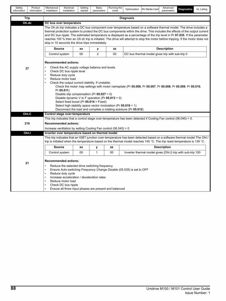
Safety information
Product information
Mechanical installation
Electrical installation
Getting started
Basic parameters
Running the motor Optimization NV Media Card Advanced
parameters Diagnostics UL Listing
Oh.dc DC bus over temperature
27
The Oh.dc trip indicates a DC bus component over temperature based on a software thermal model. The drive includes a thermal protection system to protect the DC bus components within the drive. This includes the effects of the output current and DC bus ripple. The estimated temperature is displayed as a percentage of the trip level in Pr 07.035. If this parameter reaches 100 % then an Oh.dc trip is initiated. The drive will attempt to stop the motor before tripping. If the motor does not stop in 10 seconds the drive trips immediately.
Recommended actions:• Check the AC supply voltage balance and levels • Check DC bus ripple level• Reduce duty cycle• Reduce motor load• Check the output current stability. If unstable;
Check the motor map settings with motor nameplate (Pr 05.006, Pr 05.007, Pr 05.008, Pr 05.009, Pr 05.010, Pr 05.011)Disable slip compensation (Pr 05.027 = 0)Disable dynamic V to F operation (Pr 05.013 = 0)Select fixed boost (Pr 05.014 = Fixed)Select high stability space vector modulation (Pr 05.019 = 1)Disconnect the load and complete a rotating autotune (Pr 05.012)
Oht.C Control stage over-temperature
219This trip indicates that a control stage over-temperature has been detected if Cooling Fan control (06.045) = 0.Recommended actions:Increase ventilation by setting Cooling Fan control (06.045) > 0
Oht.I Inverter over temperature based on thermal model
21
This trip indicates that an IGBT junction over-temperature has been detected based on a software thermal model.The Oht.I trip is initiated when the temperature based on the thermal model reaches 145 °C. The trip reset temperature is 139 °C.
Recommended actions:• Reduce the selected drive switching frequency• Ensure Auto-switching Frequency Change Disable (05.035) is set to OFF• Reduce duty cycle• Increase acceleration / deceleration rates• Reduce motor load • Check DC bus ripple• Ensure all three input phases are present and balanced
Trip Diagnosis
Source xx y zz Description
Control system 00 2 00 DC bus thermal model gives trip with sub-trip 0
Source xx y zz Description
Control system 00 1 00 Inverter thermal model gives Oht.I trip with sub-trip 100
88 Unidrive M100 / M101 Control User Guide Issue Number: 1

Safety information
Product information
Mechanical installation
Electrical installation
Getting started
Basic parameters
Running the motor Optimization NV Media Card Advanced
parameters Diagnostics UL Listing
Oht.P Power stage over temperature
22
This trip indicates that a power stage over-temperature has been detected. From the sub-trip ‘xxyzz’, the Thermistor location is identified by ‘zz’.
Recommended actions:• Check enclosure / drive fans are still functioning correctly• Force the heatsink fans to run at maximum speed • Check enclosure ventilation paths• Check enclosure door filters• Increase ventilation• Reduce the drive switching frequency• Reduce duty cycle• Increase acceleration / deceleration rates• Use S ramp (Pr 02.006)• Reduce motor load • Check the derating tables and confirm the drive is correctly sized for the application.• Use a drive with larger current / power rating
OI.A1 Analog input 1 over-current189 Current input on analog input 1 exceeds 24mA.
OI.AC Instantaneous output over current detected
3
The instantaneous drive output current has exceeded VM_DRIVE_CURRENT_MAX.This trip cannot be reset until 10s after the trip was initiated.Recommended actions/checks:• Increase acceleration/deceleration rate• If seen during autotune reduce the voltage boost• Check for short circuit on the output cabling• Check integrity of the motor insulation using an insulation tester• Is the motor cable length within limits for the frame size?• Reduce the values in the current loop gain parameters
OI.br Braking IGBT over current detected: short circuit protection for the braking IGBT activated
4
The OI.br trip indicates that over current has been detected in braking IGBT or braking IGBT protection has been activated.This trip cannot be reset until 10s after the trip was initiated.Recommended actions:• Check brake resistor wiring• Check braking resistor value is greater than or equal to the minimum resistance value• Check braking resistor insulation
OI.SC Output phase short-circuit
228
Over-current detected on drive output when enabled. Possible motor ground fault.Recommended actions:• Check for short circuit on the output cabling• Check integrity of the motor insulation using an insulation tester• Is the motor cable length within limits for the frame size?
Trip Diagnosis
Source xx y zz Description
Power system 01 0 zz Thermistor location in the drive defined by zz
Drive size Trip temperature (°C) Trip reset temperature (°C)
1 to 4 95 90
Unidrive M100 / M101 Control User Guide 89Issue Number: 1

Safety information
Product information
Mechanical installation
Electrical installation
Getting started
Basic parameters
Running the motor Optimization NV Media Card Advanced
parameters Diagnostics UL Listing
Out.P Output phase loss detected
98
The Out.P trip indicates that phase loss has been detected at the drive output.
If Pr 05.042 = 1, the physical output phases are reversed, and so sub-trip 3 refers to physical output phase V and sub-trip 2 refers to physical output phase W.Recommended actions:• Check motor and drive connections• To disable the trip set Output Phase Loss Detection Enable (06.059) = 0
OV DC bus voltage has exceeded the peak level or maximum continuous level for 15 seconds
2
The OV trip indicates that the DC bus voltage has exceeded the VM_DC_VOLTAGE[MAX] or VM_DC_VOLTAGE_SET[MAX] for 15 s. The trip threshold varies depending on voltage rating of the drive as shown below.
Sub-trip Identification
Recommended actions:• Increase deceleration ramp (Pr 00.004)• Decrease the braking resistor value (staying above the minimum value)• Check nominal AC supply level• Check for supply disturbances which could cause the DC bus to rise• Check motor insulation using an insulation tester
Trip Diagnosis
Sub-trip Reason1 U phase detected as disconnected when drive enabled to run.2 V phase detected as disconnected when drive enabled to run.3 W phase detected as disconnected when drive enabled to run.
4 The drive output frequency is above 4 Hz and a phase is disconnected for the time specified by Output Phase Loss Detection Time (06.058).
NOTE
Voltage rating VM_DC_VOLTAGE[MAX] VM_DC_VOLTAGE_SET[MAX]100 510 400200 510 400400 870 800
Source xx y zzControl system 00 0 01: Instantaneous trip when the DC bus voltage exceeds
VM_DC_VOLTAGE[MAX].Control system 00 0 02: Time delayed trip indicating that the DC bus voltage is above
VM_DC_VOLTAGE_SET[MAX].Power system 01 0 00: Instantaneous trip when the DC bus voltage exceeds
VM_DC_VOLTAGE[MAX].
90 Unidrive M100 / M101 Control User Guide Issue Number: 1

Safety information
Product information
Mechanical installation
Electrical installation
Getting started
Basic parameters
Running the motor Optimization NV Media Card Advanced
parameters Diagnostics UL Listing
P.dAt Power system configuration data error
220
The P.dAt trip indicates that there is an error in the configuration data stored in the power system. This trip is generated from within the drive control system or from the power system. The trip is related to the table uploaded from the power system at power-up.
Recommended actions:• Hardware fault – Contact the supplier of the drive
Pb.bt Power board is in bootloader mode
245Power board is in bootloader modeRecommended actions:• Contact the supplier of the drive.
Pb.Er Communication has been lost / errors detected between control and power processor
93
The Pb.Er trip is initiated if there is no communications between the control board processor and the power board processor. The reason for the trip can be identified by the sub-trip number.
Recommended actions:• Hardware fault – Contact the supplier of the drive
Pb.HF Power board HF
235
Power processor hardware fault. The sub-trip number is the HF code.Recommended actions:• Hardware fault - Contact the supplier of the drive
Pd.S Power down save error
37The Pd.S trip indicates that an error has been detected in the power down save parameters saved in non-volatile memory. Recommended actions:• Perform a 1001 save in Pr mm.000 to ensure that the trip doesn’t occur the next time the drive is powered up.
Trip Diagnosis
Source xx y zz DescriptionControl system 00 0 01 No data was obtained from the power board.
Control system 00 0 02 There is no data table.
Control system 00 0 03 The power system data table is bigger than the space available in
the control pod to store it.
Control system 00 0 04 The size of the table given in the table is incorrect.
Control system 00 0 05 Table CRC error.
Control system 00 0 06 The version number of the generator software that produced the
table is too low.
Control system 0 0 07 The power data table failed to be stored in the power board.
Power system 01 0 00 The power data table used internally by the power module has an
error.Power system 01 0 01 The power data table that is uploaded to the control system on
power up has an error.Power system 01 0 02 The power data table used internally by the power module does
not match the hardware identification of the power module.
Sub-trip Reason1 PLL operating region out of lock2 Power board lost communication with user board3 User board lost communication with power board4 Communication CRC error
Unidrive M100 / M101 Control User Guide 91Issue Number: 1

Safety information
Product information
Mechanical installation
Electrical installation
Getting started
Basic parameters
Running the motor Optimization NV Media Card Advanced
parameters Diagnostics UL Listing
PH.Lo Supply phase loss
32
The PH.Lo trip indicates that the drive has detected an input phase loss or large supply imbalance. The drive will attempt to stop the motor before this trip is initiated. If the motor cannot be stopped in 10 seconds the trip occurs immediately. The PH.Lo trip works by monitoring the ripple voltage on the DC bus of the drive, if the DC bus ripple exceeds the threshold, the drive will trip on PH.Lo. Potential causes of the DC bus ripple are input phase loss, Large supply impedance and severe output current instability.
Input phase loss detection can be disabled when the drive is required to operate from the DC supply or from a single phase supply in Input Phase Loss Detection Mode (06.047).
Recommended actions:• Check the AC supply voltage balance and level at full load• Check the DC bus ripple level with an isolated oscilloscope• Check the output current stability• Check for mechanical resonance with the load• Reduce the duty cycle• Reduce the motor load• Disable the phase loss detection, set Pr 06.047 to 2.
PSU Internal power supply fault
5
The PSU trip indicates that one or more internal power supply rails are outside limits or overloaded.
Recommended actions:• There is a hardware fault within the drive – return the drive to the supplier
r.b.ht Hot rectifier/brake
250Over-temperature detected on input rectifier or braking IGBT.Recommended action:• Increase ventilation by setting Cooling Fan Control (06.045) > 0.
Reserved Reserved trips 010912
14-1723, 2938, 39
90 - 91, 92, 94 - 9699
101 - 109111
168 - 172176 - 177190 - 198205 - 217222 - 224
229 - 230, 233238 - 244
249, 251 - 254
These trip numbers are reserved trip numbers for future use.
Trip Diagnosis
Source xx y zz
Control system 00 0
00: Phase loss detected based on control system feedback. The drive attempts to stop the drive before tripping unless bit 2 of Action On Trip Detection (10.037) is set to one.
Source xx y zz DescriptionControl system 00 0
00 Internal power supply overload.Power system 01 1
Trip Number Description01, 09, 12, 14-17, 23, 29, 38, 39 Reserved resettable trip
90, 91, 92, 94-96, 99 Reserved resettable trip101 - 109, 111 Reserved resettable trip
168-172, 176-177 Reserved resettable trip190 – 198 Reserved resettable trip205-217 Reserved resettable trip222-224 Reserved non-resettable trip
229-230, 233 Reserved non-resettable trip238 - 244, 249 Reserved non-resettable trip
251-254 Reserved non-resettable trip
92 Unidrive M100 / M101 Control User Guide Issue Number: 1

Safety information
Product information
Mechanical installation
Electrical installation
Getting started
Basic parameters
Running the motor Optimization NV Media Card Advanced
parameters Diagnostics UL Listing
rS Measured resistance has exceeded the parameter range
33
The rS trip indicates that the measured stator resistance of the motor during an autotune test has exceeded the maximum possible value of Stator Resistance (05.017).
If the measured value or a value written to this parameter by the user exceeds (VFS/√2) / Full Scale Current Kc (11.061),where VFS is the full scale DC bus voltage then this trip is initiated.The stationary autotune is initiated using the autotune function (Pr 05.012) or in open loop vector mode (Pr 05.014) on the first run command after power up in mode 4 (Ur_I) or on every run command in modes 0 (Ur_S) or 3 (Ur_Auto). This trip can occur if the motor is very small in comparison to the rating of the drive.If the value is the result of a measurement made by the drive then sub-trip 0 is applied, or if it is because the parameter has been changed by the user then sub-trip 3 is applied. During the stator resistance section of auto-tuning an additional test is performed to measure the drive inverter characteristics to provide the compensation necessary for dead-times. If the inverter characteristic measurement fails then sub-trip 2 is applied.The reason for the trip can be identified by the sub-trip number.
Recommended actions:• Check that a value has not been entered in the stator resistance for the presently selected motor map that exceeds the
allowed range.• Check the motor cable / connections• Check the integrity of the motor stator winding using a insulation tester• Check the motor phase to phase resistance at the drive terminals• Check the motor phase to phase resistance at the motor terminals• Ensure the stator resistance of the motor falls within the range of the drive model• Select fixed boost mode (Pr 05.014 = Fd) and verify the output current waveforms with an oscilloscope• Replace the motor
So.St Soft start relay failed to close, soft start monitor failed
226
The So.St trip indicates that the soft start relay in the drive failed to close or the soft start monitoring circuit has failed.The cause of the trip can be identified by the sub-trip number.
Recommended actions:• Hardware fault – Contact the supplier of the drive
St.HF Hardware trip has occurred during last power down
221
The St.HF trip indicates that a hardware trip (HF01 –HF18) has occurred and the drive has been power cycled. The sub-trip number identifies the HF trip.
Recommended actions:• Enter 1299 in Pr mm.000 and press reset to clear the trip
Sto No Safe Torque Off board fitted
234Internal STO board not fitted correctlyRecommended actions:Hardware fault – Contact the supplier of the drive
th.br Brake resistor over temperature
10
The th.br trip is initiated if the hardware based braking resistor thermal monitoring is connected and the resistor overheats. If the braking resistor is not used, then this trip must be disabled with bit 3 of Action On Trip Detection (10.037) to prevent this trip.Recommended actions:• Check brake resistor wiring• Check braking resistor value is greater than or equal to the minimum resistance value• Check braking resistor insulation
Trip Diagnosis
Sub-trip Reason
0 Stator resistance (5.017) test failed during Autotune or measured stator resistance value is out of range.
1 Reserved
2 Transient inductance (5.024) test failed during Autotune or measured stator resistance value is out of range.
3 The value of Stator Resistance (05.017) is too large when the parameter is edited.
4 Stator resistance (5.017) test successful during Autotune but Pr 05.017 is too large for this drive current and voltage rating.
Sub-trip Reason1 Soft-start failure2 DC bus capacitor failure on 110 V drive
Unidrive M100 / M101 Control User Guide 93Issue Number: 1

Safety information
Product information
Mechanical installation
Electrical installation
Getting started
Basic parameters
Running the motor Optimization NV Media Card Advanced
parameters Diagnostics UL Listing
The trips can be grouped into the following categories. It should be noted that a trip can only occur when the drive is not tripped or is already tripped but with a trip with a lower priority number.Table 11-3 Trip categories
11.5 Internal / Hardware tripsTrips HF01 to HF23 are internal faults that do not have trip numbers except HF08, HF11, HF12 and HF18. If one of these trips occurs, the main drive processor has detected an irrecoverable error. All drive functions are stopped and the trip message will be displayed on the drive keypad. If a non permanent trip occurs this may be reset by power cycling the drive. On power up after it has been power cycled the drive will trip on St.HF (the sub-trip number indicates the HF fault code). Enter 1299 in mm.000 to clear the Stored HF trip.
tH.Fb Internal thermistor has failed
218
The tH.Fb trip indicates that an internal thermistor has failed in the drive (i.e. open circuit or short circuit). The thermistor location can be identified by the sub-trip number.
Recommended actions:• Hardware fault – Contact the supplier of the drive
tun.S Autotune test stopped before completion
18
The drive was prevented from completing an autotune test, because either the drive enable or the drive run were removed.
Recommended actions:• Check the drive enable signal (Terminal 11) was active during the autotune• Check the run command was active in digtal input 3 or 4 state (Pr 08.003 or Pr 08.004) during the autotune.
tun.1 Required speed could not be reached
11
The drive has tripped during an autotune. The cause of the trip can be identified from the sub-trip number.
Recommended actions:• Ensure the motor is free to turn i.e. mechanical brake is released
U.OI User OI ac 8 The U.OI trip is initiated if the output current of the drive exceeds the trip level set by User Over Current Trip Level (04.041).
U.S User Save error / not completed
36
The U.S trip indicates that an error has been detected in the user save parameters saved in non-volatile memory. For example, following a user save command, If the power to the drive was removed when the user parameters were being saved.
Recommended actions:• Perform a user save in Pr mm.000 to ensure that the trip doesn’t occur the next time the drive is powered up.• Ensure that the drive has enough time to complete the save before removing the power to the drive.
Trip Diagnosis
Source xx y zz
Power system 01 0 Thermistor location defined by zz
Sub-trip Reason2 The motor did not reach the required speed during rotating autotune.
Priority Category Trips Comments
1 Internal faults HFxx These indicate internal problems and cannot be reset. All drive features are inactive after any of these trips occur.
1 Stored HF trip St.HF This trip cannot be cleared unless 1299 is entered into Parameter (mm.000) and a reset is initiated.
2 Non-resettable trips Trip numbers 218 to 247 These trips cannot be reset.
3 Volatile memory failure EEF This can only be reset if Parameter mm.000 is set to 1233 or 1244, or if Load Defaults (11.043) is set to a non-zero value.
4 NV Media Card trips Trip numbers 174, 175 and 177 to 188 These trips are priority 5 during power-up.
4 Internal 24V PSU
5 Trips with extended reset times
OI.AC, OI.br, and FAn.F. These trips cannot be reset until 10 s after the trip was initiated.
5Phase loss and d.c. jumper power circuit protection
PH.Lo and Oh.dc
The drive will attempt to stop the motor before tripping if a PH.Lo trip occurs unless this feature has been disabled (see Action On Trip Detection (10.037). The drive will always attempt to stop the motor before tripping if an Oh.dc occurs.
5 Standard trips All other trips
94 Unidrive M100 / M101 Control User Guide Issue Number: 1

Safety information
Product information
Mechanical installation
Electrical installation
Getting started
Basic parameters
Running the motor Optimization NV Media Card Advanced
parameters Diagnostics UL Listing
11.6 Alarm indicationsIn any mode, an alarm is an indication given on the display by alternating the alarm string with the drive status string display. If an action is not taken to eliminate any alarm except "tuning”, “LS" and “24.LoSt” the drive may eventually trip. Alarms are not displayed when a parameter is being edited.
Table 11-4 Alarm indications
11.7 Status indicationsTable 11-5 Status indications
Table 11-6 Status indications at power-up
11.8 Displaying the trip historyThe drive retains a log of the last ten trips that have occurred. Trip 0 (10.020) to Trip 9 (10.029) store the most recent 10 trips that have occurred where Trip 0 (10.020) is the most recent and Trip 9 (10.029) is the oldest. When a new trip occurs it is written to Trip 0 (10.020) and all the other trips move down the log, with oldest being lost. The date and time when each trip occurs are also stored in the date and time log, i.e. Trip 0 Date (10.041) to Trip 9 Time (10.060). The date and time are taken from Date (06.016) and Time (06.017). Some trips have sub-trip numbers which give more detail about the reason for the trip. If a trip has a sub-trip number its value is stored in the sub-trip log, i.e. Trip 0 Sub-trip Number (10.070) to Trip 9 Sub-trip Number (10.079). If the trip does not have a sub-trip number then zero is stored in the sub-trip log.
Alarm string Description
br.res Brake resistor overload. Braking Resistor Thermal Accumulator (10.039) in the drive has reached 75.0 % of the value at which the drive will trip.
OV.Ld Motor Protection Accumulator (04.019) in the drive has reached 75.0 % of the value at which the drive will trip and the load on the drive is >100 %.
d.OV.Ld Drive over temperature. Percentage Of Drive Thermal Trip Level (07.036) in the drive is greater than 90 %.tuning The autotune procedure has been initialized and an autotune in progress.
LS Limit switch active. Indicates that a limit switch is active and that is causing the motor to be stopped.Lo.AC Low voltage mode. See Low AC Alarm (10.107).I.AC.Lt Current limit active. See Current Limit Active (10.009).24.LoSt 24V backup not present. See 24V Alarm Loss Enable (11.098).
String Description Drive output stage
inh The drive is inhibited and cannot be run. Either the drive enable signal is not applied to the drive enable terminals or Pr 06.015 is set to 0. Disabled
rdy The drive is ready to run. The drive enable is active, but the drive inverter is not active because the final drive run is not active. Disabled
Stop The drive is stopped / holding zero speed. EnabledS.Loss Supply loss condition has been detected. Enableddc.inj The drive is applying dc injection braking. Enabled
Er The drive has tripped and no longer controlling the motor. The trip code appears in the display. DisabledUV The drive is in the under voltage state either in low voltage or high voltage mode. Disabled
HEAt The motor pre-heat function is active. Enabled
String StatusPS.LOAD Waiting for power stage
The drive is waiting for the processor in the power stage to respond after power-up
Unidrive M100 / M101 Control User Guide 95Issue Number: 1

Safety information
Product information
Mechanical installation
Electrical installation
Getting started
Basic parameters
Running the motor Optimization NV Media Card Advanced
parameters Diagnostics UL Listing
11.9 Behavior of the drive when trippedIf the drive trips, the output of the drive is disabled so the load coasts to a stop. If any trip occurs, the following read only parameters are frozen until the trip is cleared. This is to help diagnose the cause of the trip.
If the parameters are not required to be frozen then this can be disabled by setting bit 4 of Pr 10.037.
Parameter Description01.001 Frequency reference01.002 Pre-skip filter reference01.003 Pre-ramp reference01.069 Reference in rpm01.070 Clamped reference02.001 Post-ramp reference03.001 Final demand ref04.001 Current magnitude04.002 Active current04.017 Reactive current05.001 Output frequency05.002 Output voltage05.003 Power05.005 DC bus voltage07.001 Analog input 1
96 Unidrive M100 / M101 Control User Guide Issue Number: 1

Safety information
Product information
Mechanical installation
Electrical installation
Getting started
Basic parameters
Running the motor Optimization NV Media Card Advanced
parameters Diagnostics UL Listing
Unidrive M100 / M101 Control User Guide 97Issue Number: 1
12 UL Listing12.1 UL file referenceAll products covered by this Guide are UL Listed to both Canadian and US requirements. The UL file reference is: NMMS/7.E171230.
12.2 Option modules, kits and accessoriesAll Option Modules, Control Pods and Installation Kits supplied by Emerson Industrial Automation for use with these drives are UL Listed.
12.3 Enclosure ratingsDrives are UL Open Type as supplied.Drives fitted with a conduit box are UL Type 1.
12.4 MountingDrives can be mounted directly onto a vertical surface. This is known as 'surface' or 'standard' mounting. Refer to relevant Power Installation Guide for further information.Drives can be installed side by side with recommended spacing between them. This is known as 'bookcase' mounting. Refer to relevant Power Installation Guide for further information.Drives fitted with a conduit box can be mounted directly onto a wall or other vertical surface without additional protection. Suitable conduit boxes are available from Emerson Industrial Automation.
12.5 EnvironmentDrives must be installed in a Pollution Degree 2 environment or better (dry, non-conductive pollution only).All drives are capable of delivering full rated output current at surrounding air temperatures up to 40 °C. Drives may be operated in surrounding air temperatures up to 50 °C or 55 °C at de-rated current, depending on the model number. Refer to relevant Power Installation Guide for further information.
12.6 Electrical InstallationTERMINAL TORQUETerminals must be tightened to the rated torque as specified in the Installation Instructions. Refer to relevant Power Installation Guide for further information.WIRING TERMINALSDrives must be installed using cables rated for 75 °C operation, copper wire only. UL Listed closed-loop connectors sized according to the field wiring shall be used for all field wiring connections. Refer to relevant Power Installation Guide for further information.BRANCH CIRCUIT PROTECTIONThe fuses and circuit breakers required for branch circuit protection are contained in the Installation Instructions. Refer to relevant Power Installation Guide for further information.OPENING OF BRANCH CIRCUITOpening of the branch-circuit protective device may be an indication that a fault has been interrupted. To reduce the risk of fire or electric shock, the equipment should be examined and replaced if damaged. If burnout of the current element of an overload relay occurs, the complete overload relay must be replaced. Integral solid state short circuit protection does not provide branch circuit protection. Branch circuit protection must be provided in accordance with the National Electrical Code and any additional local "codes".
DYNAMIC BRAKINGDrives with model numbers beginning M100, M101, M200, M201, M300 or M400 have been evaluated for dynamic braking applications.
12.7 Motor overload protection and thermal memory retention
All drives incorporate internal overload protection for the motor load that does not require the use of an external or remote overload protection device.The protection level is adjustable and the method of adjustment is provided in section 8.4 Motor thermal protection on page 38. Maximum current overload is dependent on the values entered into the current limit parameters (motoring current limit, regenerative current limit and symmetrical current limit entered as percentage) and the motor rated current parameter (entered in amperes). The duration of the overload is dependent on motor thermal time constant. The time constant is programmable. The default overload protection is typically set to 150 % of the motor rated current for 120 seconds.The method of adjustment of the overload protection is provided in the Installation Instructions shipped with the product.All models are provided with thermal memory retention.
12.8 Electrical supplyThe drives are suitable for use on a circuit capable of delivering not more than 10,000 RMS Symmetrical Amperes, at rated voltage when protected by circuit breakers as specified in the Installation Instructions.
12.9 External Class 2 supplyThe external power supply used to power the 24 V control circuit shall be marked: "UL Class 2". The power supply voltage shall not exceed 24 Vdc.
12.10 Group Installation and Modular Drive Systems
Drives with DC+ and DC- supply connections, with 230 V or 480 V supply voltage rating, are UL approved for use in modular drive systems as inverters when supplied by the converter sections: Mentor MP25A, 45A, 75A, 105A, 155A or 210A range manufactured by Emerson Industrial Automation. Alternatively, the inverters may be supplied by converters from the Unidrive-M range manufactured by Emerson Industrial Automation.In these applications the inverters are required to be additionally protected by supplemental fuses.Drives have not been evaluated for other Group Installation applications, for example where a single inverter is wired directly to two or more motors. In these applications, additional thermal overload protection is needed. Contact Emerson Industrial Automation for further details.

IndexAAcceleration ............................................................................34Advanced menus ....................................................................19Advanced parameters .............................................................44Alarm .......................................................................................95Alarm Indications ....................................................................95Autotune ..................................................................................36
BBasic requirements .................................................................32
CCautions ....................................................................................6Control connections ................................................................13Control terminal specification ..................................................14Current limits ...........................................................................38
DDeceleration ............................................................................34Defaults (restoring parameter) ................................................19Destination parameter .............................................................13Diagnostics .............................................................................80Display ....................................................................................16Display messages ...................................................................19
FField weakening (constant power) operation ..........................38Fixed V/F mode .........................................................................9GGetting Started ........................................................................16
KKeypad ....................................................................................16
MMagnetising current .................................................................49Mechanical Installation ............................................................12Menu 0 ....................................................................................18Menu 01 - Frequency / speed reference .................................52Menu 02 - Ramps ....................................................................56Menu 03 - Slave frequency, speed feedback and speed control .....................................................................59Menu 04 - Torque and current control .....................................61Menu 05 - Motor control ..........................................................63Menu 06 - Sequencer and clock .............................................66Menu 07 - Analog I/O ..............................................................68Menu 08 - Digital I/O ...............................................................70Menu 10 - Status and trips ......................................................74Menu 11 - General drive set-up ..............................................76Menu 22 - Additional Menu 0 set-up .......................................78Menu structure ........................................................................18Minimum connections to get the motor running in any operating mode ..........................................................33Mode parameter ......................................................................13Motor (running the motor) .......................................................32Motor number of poles ............................................................35Motor rated current ..................................................................35Motor rated current (maximum) ...............................................38Motor rated frequency .............................................................35Motor rated power factor .................................................. 35, 49Motor rated speed ...................................................................35Motor rated voltage .................................................................35Motor thermal protection .........................................................38
NNotes .........................................................................................6OOpen loop mode ........................................................................9Open loop vector mode .............................................................9Operating modes .......................................................................9Optimization ............................................................................35Options ....................................................................................11
PParameter access level ...........................................................20Parameter ranges ...................................................................45Parameter security ..................................................................20Product information ...................................................................7
QQuick start commissioning / Start-up ......................................34Quick start connections ...........................................................32
RRelay contacts .........................................................................15
SSafety Information .....................................................................6Saving parameters ..................................................................19Single line descriptions ...........................................................21Square V/F mode ......................................................................9Status ......................................................................................95Status Indications ....................................................................95Switching frequency ................................................................38
98 Unidrive M100 / M101 Control User Guide Issue Number: 1

TTrip ..........................................................................................80Trip History ..............................................................................95Trip Indications ........................................................................80
UUser Security ...........................................................................20
VVoltage mode ................................................................... 36, 37
WWarnings ...................................................................................6
Unidrive M100 / M101 Control User Guide 99Issue Number: 1

0478-0352-01