control valves single-seated globe valve type 3222 type
TRANSCRIPT

Control ValvesSingle-seated Globe Valve Type 3222
Type 3222/2780-1 and Type 3222/2780-2 ⋅ with pneumatic actuators
Type 3222/5821 and Type 3222/5822 ⋅ with electric actuators
ApplicationControl valves for light industrial and HVAC requirements.Sizes ½" to 2" ⋅ Nominal pressure ANSI Class 250Temperatures up to 390 °F (200 °C) for water and steamor up to 300 °F (150 °C) for water, oil and other liquids
Features• Single-seated globe valves• Pressure-balanced valve plugs• Low height and weight• Available with female/male threaded ends, welding ends,
or flanges• Quick-exchange actuator connection
VersionsType 3222 ⋅ Globe ValveType 3222/2780-1 ⋅ Pneumatic Control Valvewith Type 2780-1 Pneumatic Actuator.Type 3222/2780-2 ⋅ Pneumatic Control Valve (Fig. 1)with Type 2780-2 Pneumatic Actuatorfor integral positioner attachment.Type 3222/5821 ⋅ Electric Control Valve (Fig. 2)with Type 5821 Electric Actuator.Type 3222/5822 ⋅ Electric Control Valvewith Type 5822 Electric Actuatorvalve closed in fail-safe position.
Special Versions– Reduced Cvs (Kvs) values– Oil-resistant stuffing box
Accessories and combinations– Type 2780-1 or Type 2780-2 Pneumatic Actuators;
for details see Technical Data Sheet T 5840 E– Type 3760 Pneumatic or Electropneumatic Positioners;
for details see Technical Data Sheet T 8385 E– Type 5821 or Type 5822 Electric Actuators:
for details see Technical Data Sheet T 5822 E
For DIN versions see Technical Data Sheet T 5866 E.
Fig. 1 ⋅ Type 3222/2780-2 Pneumatic Control Valve withType 3222 Globe Valve, Type 2780-2 PneumaticActuator and Type 3760 Positioner
Edition September 1996 ANSI Version
Technical Data Sheet T 5866
Associated Information Sheet T 5800
The control valves consist of a globe valve and either a pneumaticactuator or electric actuator, and optional positioner
Fig. 2 ⋅ Type 3222/5821 Electric Control Valve withType 3222 Globe Valve and Type 5821 ElectricActuator

Principle of operation (Figs. 3 and 4)The process medium flows through the single-seated globe valvein the direction indicated by the arrow. The valve plug positiondetermines the cross-sectional area of flow between the plug (3)and the valve seat (2). The plug stem (4) with the attached plug ispositively pressed to the connecting rod of the actuator (10)(force-locking connection). The valve is opened by the valve spring(5) when the actuator stem is retracted.For water with temperatures above 300 °F (150 °C) and steam,a version with extension piece is required (Fig. 4).
Pneumatic actuatorsPneumatic actuators are available with two fail-safe actions,“spring force extends actuator stem” and “spring force retractsactuator stem”. In the version “spring force extends actuator stem”,the actuator springs close the valve on loss of air supply, whereasin the version “spring force retracts actuator stem” they open thevalve.
Accessories for pneumatic actuators– Positioners are used generally when a pneumatic controller or
i/p transducer output alone is not sufficient for satisfactoryvalve operation. They provide the advantages of ability toadjust the valve stroking speed, the sensitivity of response(gain), the valve travel range, and boost the signal to theactuator as required for higher actuator spring ranges, coun-teraction of increasing valve friction or providing tight shutoffwith fail open actuators. Positioners are also used to reversethe valve action without changing the failure action, or for splitrange operation (e.g. two valves operating in tandem with acommon input signal).
Electric actuatorsType 5821 and Type 5822 Electric Actuators can be equippedwith the additional optional electrical equipment listed in thesection “Technical data”, Table 3.
Electric actuators with fail-safe actionType 5822 are fitted with an electromagnet and spring assemblywhich can be connected in a safety interlock circuit. Whenever thecontrol circuit is interrupted or failure of supply power occurs, theelectromagnet disengages the gear reduction from the self-lockingmotor and the spring assembly forces the valve to the fail position.
Accessories for electric actuators:– Limit switches can be used to indicate whenever a set limit value
is exceeded in either direction.– A potentiometer serves for the remote indication of the valve
stem position.– The electric positioner is designed for standardized input con-
trol signals from 4 to 20 mA, 0 to 20 mA, 0 to 10 V dc andassociated split-range operation.
Legend to Figs. 3 and 41 Valve body2 Seat3 Plug4 Plug stem5 Valve spring
10
6
5432
1
8
Fig. 3 ⋅ Type 3222/2780-1 Pneumatic Control Valve,version for temperatures up to 300 °F (150 °C)with balancing piston
10
5
4
7
3
2
1
Fig. 4 ⋅ Type 3222/5821 Electric Control Valve, versionwith extension piece for temperatures up to 390 °F(200 °C), with balancing bellows
T 58662
6 Guide nipple7 Balancing bellows8 Balancing piston10 Actuator
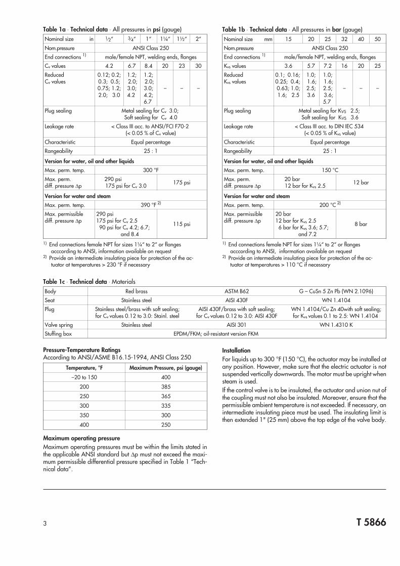
InstallationFor liquids up to 300 °F (150 °C), the actuator may be installed atany position. However, make sure that the electric actuator is notsuspended vertically downwards. The motor must be upright whensteam is used.If the control valve is to be insulated, the actuator and union nut ofthe coupling must not also be insulated. Moreover, ensure that thepermissible ambient temperature is not exceeded. If necessary, anintermediate insulating piece must be used. The insulating limit isthen extended 1" (25 mm) above the top edge of the valve body.
T 58663
Table 1a ⋅ Technical data ⋅ All pressures in psi (gauge)Nominal size in 1⁄2“ 3⁄4“ 1“ 1¼“ 1½“ 2“
Nom.pressure ANSI Class 250
End connections 1) male/female NPT, welding ends, flanges
Cv values 4.2 6.7 8.4 20 23 30
ReducedCv values
0.12; 0.2;0.3; 0.5;0.75; 1.2;2.0; 3.0
1.2;2.0;3.0;4.2
1.2;2.0;3.0;4.2;6.7
– – –
Plug sealing Metal sealing for Cv 3.0;Soft sealing for Cv 4.0
Leakage rate < Class III acc. to ANSI/FCI F70-2(< 0.05 % of Cv value)
Characteristic Equal percentage
Rangeability 25 : 1
Version for water, oil and other liquids
Max. perm. temp. 300 °F
Max. perm.diff. pressure ∆p
290 psi175 psi for Cv 3.0 175 psi
Version for water and steam
Max. perm. temp. 390 °F 2)
Max. permissiblediff. pressure ∆p
290 psi175 psi for Cv 2.590 psi for Cv 4.2; 6.7;
and 8.4
115 psi
1) End connections female NPT for sizes 1¼“ to 2“ or flangesacccording to ANSI, information available on request
2) Provide an intermediate insulating piece for protection of the ac-tuator at temperatures > 230 °F if necessary
Table 1b ⋅ Technical data ⋅ All pressures in bar (gauge)Nominal size mm 15 20 25 32 40 50
Nom.pressure ANSI Class 250
End connections 1) male/female NPT, welding ends, flanges
Kvs values 3.6 5.7 7.2 16 20 25
ReducedKvs values
0.1; 0.16;0.25; 0.4;0.63; 1.0;1.6; 2.5
1.0;1.6;2.5;3.6
1.0;1.6;2.5;3.6;5.7
– – –
Plug sealing Metal sealing for KVS 2.5;Soft sealing for KVS 3.6
Leakage rate < Class III acc. to DIN IEC 534(< 0.05 % of Kvs value)
Characteristic Equal percentage
Rangeability 25 : 1
Version for water, oil and other liquids
Max. perm. temp. 150 °C
Max. perm.diff. pressure ∆p
20 bar12 bar for Kvs 2.5 12 bar
Version for water and steam
Max. perm. temp. 200 °C 2)
Max. permissiblediff. pressure ∆p
20 bar12 bar for Kvs 2.56 bar for Kvs 3.6; 5.7;
and 7.2
8 bar
1) End connections female NPT for sizes 1¼“ to 2“ or flangesacccording to ANSI, information available on request
2) Provide an intermediate insulating piece for protection of the ac-tuator at temperatures > 110 °C if necessary
Table 1c ⋅ Technical data ⋅ MaterialsBody Red brass ASTM B62 G – CuSn 5 Zn Pb (WN 2.1096)
Seat Stainless steel AISI 430F WN 1.4104
Plug Stainless steel/brass with soft sealing;for Cv values 0.12 to 3.0: Stainl. steel
AISI 430F/brass with soft sealing;for Cv values 0.12 to 3.0: AISI 430F
WN 1.4104/Cu Zn 40with soft sealing;for Kvs values 0.1 to 2.5: WN 1.4104
Valve spring Stainless steel AISI 301 WN 1.4310 K
Stuffing box
Pressure-Temperature RatingsAccording to ANSI/ASME B16.15-1994, ANSI Class 250
Temperature, °F Maximum Pressure, psi (gauge)
–20 to 150 400
200 385
250 365
300 335
350 300
400 250
Maximum operating pressureMaximum operating pressures must be within the limits stated inthe applicable ANSI standard but ∆p must not exceed the maxi-mum permissible differential pressure specified in Table 1 “Tech-nical data”.
EPDM/FKM; oil-resistant version FKM

Table 2a ⋅ Technical data relating to pneumatic actuatorsNominal valve size ½“ to 2“
Effective diaphragm area in2 18.6
Maximum air supply psi 60
Fail-safe action (open/closed) Reversible
Rated valvetravel
½“ to 1“ in 0.25
1½“ to 2“ in 0.5
Benchrange
Type 2780-1 psi 6 to 15
Type 2780-2 psi 6 to 30
Required supply air pressure psi 36
Number of installed springs 3 1)
Leakage rate Scfm < 21
Signal pressure connection Type 2780-1 ISO 288/1, G1⁄8;NPT1⁄8
Ambient temperature °F 15 to 175
Table 2b ⋅ Technical data relating to pneumatic actuatorsNominal valve size 15 to 50 mm
Effective diaphragm area cm2 120
Maximum air supply bar 4
Fail-safe action (open/closed) Reversible
Ratedvalve travel
15 to 25 mm mm 6
32 to 50 mm mm 12
Benchrange
Type 2780-1 bar 0.4 to 1
Type 2780-2 bar 0.4 to 2
Required supply air pressure bar 2.4
Number of installed springs 3 1)
Leakage rate ln/h < 10
Signal pressure connection Type 2780-1 ISO 288/1, G1⁄8;NPT1⁄8
Ambient temperature °C −10 to 80
T 58664
Table 2c ⋅ Technical data relating to pneumatic actuators - MaterialsBody 2) Aluminium GD-AlSi12
Diaphragm NBR
Springs 2) Spring wire C
External bolts Chromized steel
Bushing Brass CuZn40Pb
WeightType 2780-1 lb/kg 4.4 lb 2.0 kg
Type 2780-2 lb/kg 7.0 lb 3.2 kg
1) 6 springs for a bench range from 6 to 30 psi (0.4 to 2 bar) and 0.5“ (12 mm) travel2) Not painted and surface-treated
Table 3 ⋅ Technical data relating to the electric actuatorsActuator Without fail-safe action With fail-safe action
Type 5821-5 5821-6 2) 5822-60 5822-70 2)
Nominal thrust lbf (kN) 135 (0.6) 67 (0.3) 1) 1)
Closing force of the safety spring lbf (kN) – 94 (0.42) 63 (0.28)
Valve travel in (mm) ½“ to 1“ (15 to 25 mm) : 0.2“ (5.0 mm); 1¼“ to 2“ (32 to 50 mm): 0.3“ (7.5 mm)
Transit time for rated travel s 90 (60) 40 (30) 90 (60) 40 (30)
Transit time in case of failure s – 8 5
Handwheel With Without
Power supply V ac 24, 110 or 230 24, 110 or 230
Frequency Hz 50 to 60 50 or 60
Power consumption Motor 4 VA 4 VA
Electromagnet – 5 VA
Permissible ambient temperature 30 to 120 °F ( 0 to 50 °C);at point of connection between motor and valve max. 230 °F (110 °C)
Enclosure protection rating IP 44
Additional electric equipment
Limit switches 2
Potentiometer 1
Electric positioner 3) 1
For further details, see Technical Data Sheet T 5822 E
1) Depending on the spring in the globe valve used2) Only up to nominal sizes 1“ (25 mm)3) Only for power supply 24 V ac and version with potentiometer

T 58665
5.1"
H2
H3
L
R
L1
d
SW
3.15"(80)
(130
)
Type 3222/582x with welding ends
3.1"
(80)
Intermediateinsulating piece
SW
R d
LL1
H3
H2
5.1"
6.6"(168)
(130
)
Type 3222/2780-1
SW
R d
LL1
9"
6.6"
H2
H3
(168)
(230
)
Type 3222/2780-2
SW
L2
A
Version with threaded ends
SW
L3
Version with flanges
SW
L4
G
Version withfemale thread
Table 4a ⋅ Dimensions in inches and weights in lb
Nominal size in ½“ ¾“ 1“ 1¼“ 1½“ 2“
Female thread NPT 1⁄2“ 3⁄4“ 1“ – – –
Pipe Ø d 0.84 1.1 1.3 1.6 1.9 2.4
Connection R 3⁄4“ 1“ 11⁄4“ 13⁄4“ 2“ 21⁄2“
Wrench width SW 1.2 1.4 1.8 2.3 2.6 3.2
Length L 2.6 2.8 2.9 4 4.3 5.1
Length L1with welding ends 8.3 9.2 9.6 10.6 11.6 13.0
Height H21) 7.5 9.2
Height H3 1.2 2.2
Weight 2), 3) lb 4.8 5.7 6.8 10.6 11.4 16.7
Version with threaded ends (male thread)
L2 5.1 5.7 6.2 7.1 7.7 9.0
Male thread A 1⁄2“ 3⁄4“ 1“ 11⁄4“ 11⁄2“ 2“
Weight 2), 3) lb 4.8 5.7 6.8 10.6 11.4 16.7
Version with flanges (acc. to DIN) 4)
L3 5.1 6.0 6.3 7.1 8.0 9.1
Weight 2), 3) lb 7.3 9.2 10.8 16.9 18.7 25.3
Version with female thread 4)
L4 2.6 3.0 3.5 –
Female thread NPT 1⁄2“ 3⁄4“ 1“ –
Weight 2), 3) lb 4.4 4.8 5.1 –
1) For versions with intermediate insulating piece, add 3.1“2) For versions with intermediate insulating piece, add 1 lb3) For versions with pneumatic actuators, add 1 lb for Type 2780-1 and
3.7 lb for Type 2780-24) For versions with female NPT ends 1¼“ and larger, and flange
dimensions according to ANSI, information available on request
Table 4b ⋅ Dimensions in mm and weights in kg
Nominal size mm 15 20 25 32 40 50
Female thread NPT 1⁄2“ 3⁄4“ 1“ – – –
Pipe Ø d 21.3 26.8 33.7 42 48 60
Connection R 3⁄4“ 1“ 11⁄4“ 13⁄4“ 2“ 21⁄2“
Wrench width SW 30 36 46 59 65 82
Length L 65 70 75 100 110 130
Length L1with welding ends 210 234 244 268 294 330
Height H21) 190 235
Height H3 30 55
Weight 2), 3) kg 2.2 2.6 3.1 4.8 5.2 7.6
Version with threaded ends (male thread)
L2 129 144 159 180 196 228
Male thread A 1⁄2“ 3⁄4“ 1“ 11⁄4“ 11⁄2“ 2“
Weight 2), 3) kg 2.2 2.6 3.1 4.8 5.2 7.6
Version with flanges (acc. to DIN) 4)
L3 130 150 160 180 200 230
Weight 2), 3) kg 3.3 4.2 4.9 7.7 8.5 11.5
Version with female thread 4)
L4 65 75 90 –
Female thread NPT 1⁄2“ 3⁄4“ 1“ –
Weight 2), 3) kg 2 2.2 2.3 –
1) For versions with intermediate insulating piece, add 80 mm2) For versions with intermediate insulating piece, add 0.53) For versions with pneumatic actuators, add 0.5 kg for Type 2780-1
and 1.7 kg for Type 2780-24) For versions with female NPT ends 1¼“ and larger, and flange
dimensions according to ANSI, information available on request

Ordering text - Valves with Pneumatic actuatorsPneumatic Control Valve Type 3222/2780-1 or 3222/2780-2Size ... /NPT ..., ANSI 250,Max. 300 °F (150 °C), version for water, oil and other liquids/Max. 390 °F (200 °C), version for water and steamNPT male/NPT female threaded ends/welding ends/flangesCv (Kvs) ..., with/without intermediate insulating extensionPneumatic Actuator Type 2780-1or 2780-2Operating direction: Actuator stem “extends”/"retracts"Rated travel 0.25/0.5“ (6/12 mm), bench range … psi (bar),Signal pressure connection NPT 1⁄8“, Positioner Type …
Ordering text - Valves with Electric actuatorsElectric Control Valve Type 3222/5821 or 3222/5822Size .../ NPT ..., ANSI 250,Max. 300 °F (150 °C), version for water, oil and other liquids/Max. 390 °F (200 °C), version for water and steamNPT male/NPT female threaded ends/welding ends/flangesCv (Kvs) ..., with/without intermediate insulating extensionElectric Actuators Type 5821-.../Type 5822-...for 230/110/24 V ac, 50 or 60 HzAdditional electric equipment ..., optional special version
Specifications subject to change without notice.
SAMSON CONTROLS INC.1-105 Riviera DriveMarkham ⋅ Ontario ⋅ Canada ⋅ L3R 5J7Tel. (905) 474 -0354 ⋅ Telefax (905) 474-0998
SAMSON CONTROLS INC.4111 Cedar BoulevardBaytown ⋅ Texas ⋅ USA ⋅ 77520Tel. (281) 383 -3677 ⋅ Telefax (281) 383-3690 T
5866
CA
T 5866