controlled blasting for civil construction in an urban ...€¦ · senior blasting technician,...
TRANSCRIPT

Explo CoNFERENCE / mElbouRNE, viC, 8 - 9 NovEmbER 2011 107
introductionAt a total value of A$4.8 billion, Brisbane’s Airport Link Project is Australia’s biggest road infrastructure project. Scheduled for completion in mid-2012, the 6.7 km underground toll road will connect Brisbane’s central business district and the Clem Jones Tunnel (CLEM7) to the East-West Arterial Road, which leads directly to the Brisbane Airport (BrisConnections, 2010).
It will be the first major motorway to link Brisbane city to the northern suburbs and the airport precinct, allowing motorists to avoid up to 18 sets of traffic lights. The blasting contractor’s expertise in controlled blasting technology was called upon by the project leaders, to blast large areas of rock on the surface and underground, which was too hard for mechanical rock breakers to work efficiently.
During construction of the Airport Link tunnel portal at Kedron in Brisbane, a remnant pillar of rock (approximately 2250 m3) required removal from a sensitive area, next to a major arterial road and within metres of existing infrastructure. The site is surrounded by critical civil infrastructure and is within 100 m of heritage listed buildings, residences and privately owned sensitive receivers.
As the blasting contractor had been conducting more conventional construction blasting on the site for several months, they were asked to come up with a solution to excavate this remnant pillar of hard massive volcanic tuff from the site of a critical tunnel portal. This hard remnant pillar (Brisbane Tuff) was between 2 m and 6 m thick, 15 m high
and 35 m wide; with a series of concrete piles embedded at a distance of 1 m from blastholes which were required for the excavation. The embedded concrete piles would form the support structure for this section of the tunnel, and could not be damaged by blasting the pillar.
Blasting on this site was strictly controlled, because it was located in the middle of a busy construction site and tunnel portal that had to remain operational 24 hours a day. There were strict vibration limits applying to the large concrete soil mix and secant pile walls adjacent to the site, and the adjacent privately owned and heritage listed structures. The risks associated with blasting in this environment had to be managed, while complying with the site’s strict environmental limits and reducing the effects of blasting operations on nearby residents.
The scope of the work performed in this area included design, modelling, drilling and loading of the explosives, and blast clearance and shotfiring. Access to the top of the wall was limited so all products and equipment, including the 20 t drill rig, had to be lifted in and out by crane.
Due to the nature of the blast, with infrastructure 5 m directly in front of the 15 m high face, there was only ever going to be one chance to get this blast right. This was an extremely complex blast that required the use of a number of different packaged explosives, as well as innovative timing techniques only made possible by using electronic initiating systems.
1. Senior Blasting Technician, Orica Quarry and Construction, PO Box 391, Beenleigh Qld 4207. Email: [email protected]
controlled Blasting for civil construction in an urban EnvironmentR Domotor1
ABstrActBrisbane’s Airport Link is Australia’s largest road infrastructure project, worth a total value of A$4.8 billion. The project is using surface and underground blasting to excavate hard volcanic rock, Brisbane Tuff. This paper tells the story of the most challenging and difficult blast of the whole project: the removal of a remnant pillar of rock (approximately 2250 m3) next to a major arterial road and within 100 m of existing infrastructure including a number of heritage listed buildings, residences and privately owned sensitive receivers. The pillar consisted of a hard rock wall (Brisbane Tuff) between 2 m and 6 m thick, 15 m high and 35 m wide; with in situ precast concrete piles embedded within 1 m of the boundary of the pillar. Orica Australia Pty Limited was contracted by Thiess John Holland, to perform the work in this area, including design, modelling, drilling and loading of the explosives, as well as blast clearance and shotfiring. Access to the area was limited so all explosives and equipment, including the 20 t drill rig, had to be lifted in and out by crane. Due to the nature of the blast, with infrastructure 5 m directly in front of the 15 m high face, there was only ever going to be one chance to get this blast right. This was an extremely complex blast which required the use of a number of different types of packaged explosives, as well as special timing techniques only made possible by using electronic initiating systems. This type of blast is high risk, and is more typical of a building demolition in the urban environment. The blast was fired on the 25 September 2010, and was highly successful. The environmental results for vibration and overpressure were well under the imposed limits, and the embedded concrete piles remained undamaged.
Domotor_25.indd 107 10/10/2011 10:41:02 AM

Explo CoNFERENCE / mElbouRNE, viC, 8 - 9 NovEmbER 2011
r domotor
108
Why BlAst?The pillar of rock could have been removed systematically by mechanical means during excavation of the site. However the construction design at that point in time required a minimum of 2 m of rock to extend out past the edge of the existing roof slab for two reasons. Firstly, the rock was required to support the roof slab while the concrete cured to full strength. Secondly, the rock pillar was required to provide support to the floodwall structure, a flood protection wall that had been constructed on top of the roof slab. This floodwall had been designed to withstand a one in 100 year flood event. With the banks of the Kedron Brook just 50 m from the excavation, the integrity of the floodwall was paramount to the safety of the operations on the site and in the tunnels, all of which were below sea level. Figure 1 illustrates the site location and floodwall.
By the time the secondary means of support for the floodwall was constructed (which would allow the pillar to be removed), construction on the site beneath the floodwall had advanced to the point, where rock breakers could no longer safely reach the top of the pillar. It would have also been unsafe to have people working below the pillar while it was being removed. Removal of the pillar was essential if the construction of the rest of the structure was to meet the deadline.
There were three primary concerns which had to be addressed prior to agreeing to blast the pillar:
1. the safety of the community and protection of the principal’s reputation in relation to undertaking a high risk operation;
2. the protection of the existing infrastructure in front of and adjacent to the pillar; and
3. the integrity of the in situ precast concrete piles embedded within the rock mass, just 1 m behind the intended back row of blastholes.
A number of alternative blasting methods were considered and discussed by the principal contractors under the advice of industry experts and blasting engineers. After careful
deliberations, all of the proposed approaches were deemed to pose unacceptable risks to either the public or the integrity of the structure. This was a hold point for blasting on the project, and it wasn’t until the principal contractor had explored and ruled out all other mechanical options, that blasting became the only solution that they were willing to pursue. However, as all previously proposed options had been dismissed, an acceptable design still had to be developed.
An accurate three-dimensional model was needed to ensure all possible outcomes could be reviewed. The face of the remnant pillar was surveyed using a combination of MDL and Trimble
Laser equipment. The point cloud was resectioned into the site survey control and all surfaces were crosschecked for accuracy. All existing structure was included in the model. This included the existing roof slabs and floodwall structure, as well as all structures in front of and below the rock mass and the location of the concrete piles embedded within the rock.
For safety reasons during construction activities, the face of the rock pillar had previously been fully rock-bolted; this provided multiple paths of opportunity for explosive energy and gasses to escape. The rock bolting plans were reviewed and the location of each bolt on the face was surveyed. The surveyed location of each bolt and the dip, angle, and bearing of each bolt was introduced into the blast model. Great care had to be taken to ensure drill holes were not going to intersect with the rock bolts. The loading design also had to consider the proximity of charges to the rock bolts, to reduce the risk of energy escaping via the bolt holes. Prior to blasting, the tension on all rockbolts was released and each hole was fully grouted to assist in containing the blast energy.
The blast design that was to be developed had to take into consideration all of the primary goals. No structure could be damaged, including the concrete piles within the rock mass and all rock had to fall within the designated drop zone, which was the width of the face by 11 m deep. The drop zone extended
Fig 1 - Area to be removed.
Domotor_25.indd 108 10/10/2011 10:41:02 AM

Explo CoNFERENCE / mElbouRNE, viC, 8 - 9 NovEmbER 2011
controllEd BlAsting for civil construction in An urBAn EnvironmEnt
109
out to the 20 m high concrete boom pump, located directly in front of the face.
risk mAnAgEmEntThe next step was to prepare a detailed risk assessment and work method statement to fully understand and address the unique blasting requirements of this project. A cross-section of the workforce had input into the process, including the site engineers, blast designers, public liaison and traffic management personnel, as well as the shotfirers on the project and an independent design auditor. This risk assessment was then mapped into the primary contractor’s safety management system to ensure all risks had been addressed and this document was then used to develop a blasting management plan for this project.
Damage to the embedded concrete piles and existing roof slab structure was highlighted as the main critical risk, and special consideration for this had to be taken to ensure no damage occurred to this infrastructure. An assessment of the potential implications of the blasting activities on this infrastructure needed to be carried out. In particular, the blast designer and principal contractors required an understanding of how the blasting activities may impact upon the integrity of the concrete piles and existing roof slab, and what preventative measures that should be incorporated into the blast design.
Most standards and legislation were developed to ensure that blast-induced vibration levels are maintained at or below levels of human tolerance. They often limit the permissible levels of vibration to well below those capable of causing structural or even cosmetic damage to structures. It is well accepted that concrete structures can withstand vibration levels several orders of magnitude higher than those applied for human comfort. Vibration criteria for engineered structures are therefore higher than commonly quoted environmental conditions applied in residential areas for quarry and mine blasting.
It is also accepted that both frequency and amplitude of vibration affect the possibility of damage. For the same reasons that low frequency vibration, like earthquakes, are damaging and accompanied by low limits, high frequency vibrations, as occur from construction activities at much closer distances, result in lower displacements and correspondingly reduced chances of damage.
Section J of the Australian Standard AS2187.2 2006 recommends maximum peak particle velocities for different types of structures and for different project durations based on damage rather than human discomfort as described in the earlier versions of the same document. The standard defines cosmetic damage as the formation of hairline cracks on drywall surfaces, the growth of existing cracks in plaster or drywall surfaces or the formation of hairline cracks in the mortar joints of brick/concrete constructions. Minor damage is defined as the formation of cracks or loosening and falling of plaster or drywall surfaces, or cracks through brick/concrete blocks. The same standard proposes limits for ground vibration for control of damage to structures. The limits are shown in Table 1 and suggest a value of 100 mm/s for structures of reinforced concrete construction.
Tart, Oriard and Plump (1980) observed the effects of blasting during a concrete demolition program and correlated these with measured levels of particle motion (acceleration, velocity and strain). The measurement range covered instances where no damage was detected through to cases where concrete was heavily damaged and thrown from the structure. Their findings are summarised in Table 2 and
show levels of vibration which are of an order of magnitude higher than levels commonly stated for a similar effect.
During the 1970s, the Tennessee Valley Authority embarked on a construction program necessitating blasting very near to concrete. Because of the cost implications, a re-write of the specifications was ordered based on specific conditions, field trials and full scale blasting activities. Blasting was completed at distances ranging from tens of metres through to less than 1 m. Oriard (2002) reported on the new criteria.
The study derived a relationship between the allowable level of vibration for mass concrete as a function of the concrete age, ranging between 0 hours and 10 days or more. Oriard reported that for aged concrete, an acceptable level of vibration is 400 mm/s for blasting at distances of between 15 m - 50 m. At nearer distances, the acceptable vibration increases to 500 mm/s and at further distances, reduces to 300 mm/s.
The assessment by the principal contractors and an independent design auditor, indicated a wide variation in accepted criteria, however it was appropriately noted that in almost all cases, the levels that have been applied for specific construction activities have not resulted in any damage. It was agreed by the principal contractors that the commonly imposed limits and standards reflected to a greater degree the conservatism in the approach, rather than what may be an appropriate level to prevent damage. It was further noted that where vibration has continually increased to the level where damage has occurred, the levels are in excess of 500 mm/s.
viBrAtion mAnAgEmEntThe blasting contractor’s technical personnel worked closely with the principal contractor and an independent design consultant during the design phase of the project to research the vibration transmission characteristics of the ground, and the potential travel distance of flyrock. Vibration was estimated by analysing all of the data from previous blasting operations performed on site, as shown in Figure 2.
A relationship was developed between the level of vibration, explosive quantity and distance between the blastholes and the sensitive receivers. Based on this relationship it was determined that a maximum instantaneous charge (MIC) of 5 kg would not be expected to impact on the integrity of the concrete piles. This low MIC would allow the blast designer to effectively break the rock, without damaging the embedded concrete piles, or the roof slab and floodwall structure. A summary of these vibration predictions are outlined in Table 3.
The blast designer and shotfirer worked together to develop a unique method of loading and timing this blast. The innovative method involved loading blastholes with up to five individual explosive decks with only 5 kg of charge firing at a time to control vibration levels. With this low charge weight, decked loading was required to achieve the energy distribution necessary to effectively break the rock.
Blasting in this environment required innovative timing techniques to reduce adverse affects on the public and surrounding worksite. The blast designer implemented a firing sequence intended to generate high dominant vibration frequencies in excess of 80 Hz. At these frequencies it was estimated that the displacement of the sensitive receivers would be less than 0.34 mm, thus reducing the possibility of damage to the surrounding structures.
This innovative timing was only made possible by using an electronic blasting system available to the Australian market.
Domotor_25.indd 109 10/10/2011 10:41:02 AM

Explo CoNFERENCE / mElbouRNE, viC, 8 - 9 NovEmbER 2011
r domotor
110
This electronic detonator provides accurate, flexible and reliable sequencing and also ensures the user has two way communications with the detonators from prior to deployment right up until the moment of firing.
The i-kon™ X-414 armoured detonator was used as the primary initiation system for this section of the Airport Link project. This detonator has an armoured shell to provide high resistance to dynamic shock desensitization that may be experienced in decked loading applications. The electronic blasting system enabled the blast designer to design this blast with precise control over the maximum instantaneous charge, and the designed firing sequence. An important feature of the system is that it offers fully programmable detonator delays between 0 - 15 000 milliseconds.
ExplosivE products sElEctEdThe design called for the use of a robust, high strength, detonator sensitive explosive. The explosive had to be able to be easily and accurately deployed into the blasthole.
The Senatel™ range of explosives was selected because it is specifically designed for small diameter quarry and construction blasting applications in both wet and dry conditions, and is intended for use where charge weight and total energy needs to be managed.
With a bulk strength of 183 per cent relative to ANFO, the 55 mm packaged explosive is a chemically sensitised packaged explosive designed for use as a medium density column explosive in construction applications. This made it ideal for this application with MIC restrictions where high energy is required.
A centre traced 26 mm emulsion based presplit product was chosen for use in the presplit row. The product chosen was a detonator sensitive emulsion explosive, which is internally traced with 10 g/m detonating cord that ensures fast and complete detonation. The small diameter, high velocity of detonation, and low decoupled energy of the presplit product minimised blast damage to the walls leaving behind a smooth profile with minimal overbreak.
Fig 2 - Site data regression by independent design consultant (Heilig, 2010a).
Category Type of blasting operations Peak component particle velocity (mm/s)
Structures or architectural elements that include masonry, plaster and plasterboard in their construction
All blastingFrequency dependent damage limit criteria as in Table
J4.4.2.1
Unoccupied structures of reinforced concrete or steel construction
All blasting100mm/s maximum unless agreement is reached
with the owner that a higher limit may apply
Service elements, such as pipelines, powerlines and cables All blasting Limit to be determined by structural design methodology
TABLE 1Recommended ground vibration limits for control of damage (reproduced from AS2187.2-2006).
Effect Strain Particle Velocity (mm/s)
Theoretical static failure in tension 140μ 500
Spalling of freshly set grout 700μ 2500
Spalling of loose/weathered surface skin 1300μ 5000
Cracks develop extending from blastholes 2400μ 9500
Mass concrete blown out 3800μ 15 000
TABLE 2Summary of vibration level associated with various effects
(Tart, Oriard and Plump, 1980).
Distance from final blasthole (loaded with 26mm decoupled pre-split product) (mm)
Predicted level of vibration
(mm/s)750 620
1000 490
1250 400
1500 340
1750 300
2000 260
TABLE 3Vibration prediction by independent design consultant
(Heilig, 2010).
Domotor_25.indd 110 10/10/2011 10:41:02 AM

Explo CoNFERENCE / mElbouRNE, viC, 8 - 9 NovEmbER 2011
controllEd BlAsting for civil construction in An urBAn EnvironmEnt
111
The high energy, chemically sensitised packaged explosives gave the flexibility and energy required to break the hard massive volcanic tuff. The delivery, flexibility and energy of the products selected allowed the blast crew to achieve the design principals, strict production schedules and significantly improve risk management of the project.
thE BlAst dEsignWith the 2 m thick roof slab anchored to the top of the rock mass, and the rock pillar extending only 2 m from the underside of this slab, the drill bench was inaccessible to drill rig and blast crew. A creative plan was required to address this problem. The width of the existing roof slab, from the edge of the 15 m drop off to the base of the floodwall structure, was only 3.5 m wide, barely enough for the drill rig. To give the drill and crew access to the rock pillar it was decided to construct a sacrificial concrete block on top of the rock pillar, up to the same height as the roof slab.
This concrete block was included into the computer model and work began on creating the conceptual blasthole design. The blast designer had to visualise how the rock mass was required to flow out from its in situ position and into the drop zone. Three rows of blastholes were required. The front row would be used to thrust the bottom section of the face out into the drop zone. The middle row would be required to fragment the body of the shot so it could be easily handled by the onsite equipment. The back row would split the pillar away from the embedded concrete piles within the rock mass. This would
ensure that the energy from the blast would not propagate past the split line and damage the concrete piles. The loading design methodology is outlined in Figure 3.
The front row of blastholes had to have enough burden to ensure the rock stayed contained within the drop zone. Face burst design calculations were performed to decide exactly how much burden would be required. As there was no opportunity to develop a site constant for face burst, all calculations were based on a large degree of professional judgement and experience. The calculations indicated that with a 2.2 m burden, the front row of holes could cast up to 80 m. However by decoupling the charges it was determined this cast distance could be reduced to 50 m. A design loading of three decks of 5 kg decoupled charges with an average burden of 2.2 m was entered into the model.
The design loading of the second row was spilt into five decks over the 15 m bench height. The decks were split into a 5 kg bottom deck with offset 2.5 kg and 1.7 kg decks for the remaining four. The bottom deck ensured good fragmentation and breakout at the toe. The four offset decks allowed the blast designer, to ensure that the explosives could be evenly distributed throughout the pillar, without exceeding the required MIC to manage vibration.
The presplit row was necessary to ensure the pillar would split away from the roof slab and concrete piles cleanly. If energy from the blast propagated back under the slab or into the concrete piles, the integrity of the structure would be compromised and this would have a catastrophic impact
Fig 3 - Cross-section, blasthole loading design and calculations.
Domotor_25.indd 111 10/10/2011 10:41:02 AM

Explo CoNFERENCE / mElbouRNE, viC, 8 - 9 NovEmbER 2011
r domotor
112
on the project. However with the presplit holes only 1 m in front of the piles, the blast designer had to ensure the presplit cracked cleanly along the required line. A light powder factor of 0.56 kg/m2 was used on the 0.3 m spaced row, with only every second hole loaded. The uncharged hole between each loaded hole would ensure the energy would be sufficient to crack along the split line without damaging the concrete piles or roof slab.
The decks were sequenced with the bottom decks firing first. The intention was to have the bottom of the pillar thrust out as far from the face as was allowable. This created a void for the rock broken by the upper decks to drop into. This method of firing was needed to help control the movement of the rock mass, and ensure it fell within the designated drop zone. The angles of initiation between decks had to be considered to ensure the rock flowed down and forward into the drop zone. By sequencing the holes so that the bottom and second decks in the front holes fired with at least 55 ms/m relief between them, followed by a further 75 ms/m relief to the bottom deck in the second row, a 45° downward angle of initiation was created.
dEsign rEviEWSeveral conceptual blast designs were modelled using the blasting contractor’s proprietary software. This software allowed the blast designer to run multiple iterations and consider the fragmentation and blast induced vibration of each design, as well as determine how the rock would move and flow into the drop zone. The blasting contractor’s research and development team was engaged to simulate the proposed designs and assist in developing the successful design. Examples of these simulations are shown in Figures 4 and 5.
Considerations were made for rock properties, explosive properties, decoupling of the charges, and burden relief. A special code for modelling decoupled charges had
to be written so the unique loading plan could be accurately modelled. With the blasting contractors R&D team confirming the designer’s calculations and assumptions, the shot could be marked out and the drilling could commence.
drilling And loAdingBecause the concrete block was to be suspended right on the crest of the 15 m drop off, it had to be suitably reinforced and anchored. Reinforcing mesh would be required, however it would prove to be a major problem to the drilling if it was not placed correctly. The blast designer worked with the principal contractor to ensure that they had total control over the location of reinforcing mesh and the drill holes. As the drill plan called for 89 mm holes, it was decided that 100 mm PVC collar pipes would be used to form the collars of the holes through the concrete, as shown in Figure 6.
This was achieved by placing the 100 mm collar tubes throughout the reinforcing mesh prior to the concrete being poured. The principal contractor’s surveyors were given the drill plan, and one by one they made sure that each collar pipe was in the correct location and at the correct angle and bearing. Prior to the concrete pour, the location, angle, and bearing of each collar pipe, was crosschecked by both the blast designer and the shotfirer. The quickset concrete was given 24 hours to cure before drilling commenced.
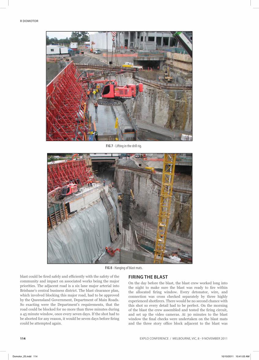
The work area for the drill was 35 m long and 3.5 m wide. It was bound by a 15 m drop off on one side and a 10 m high floodwall on the other, and each end was effectively blocked from anything other than pedestrian access. This meant that all equipment had to be brought in by crane; this included the explosives deliveries and the 20 t drill rig, which can be seen in Figure 7.
Detailed drilling logs were kept by the driller, and these logs were used to map the varying strata within the pillar. Each of the 211 drill holes were boretracked so the hole by hole face
Fig 4 - Cast profile as modelled using a numerical code (Minchinton and Lynch, 1996).
Domotor_25.indd 112 10/10/2011 10:41:02 AM

Explo CoNFERENCE / mElbouRNE, viC, 8 - 9 NovEmbER 2011
controllEd BlAsting for civil construction in An urBAn EnvironmEnt
113
burdens could be analysed and loading adjusted accordingly. Once the load plan had been modified to suit both the strata of the rock mass, and the face burdens, the final design was peer reviewed and approved.
A 55 mm packaged product was used as the primary explosive for this project. To manage the energy effectively, the blast designer had to ensure each charge was fully decoupled. As each and every deck length was known in advance, the blast designer ordered custom made 57 mm internal diameter cardboard tubes to the exact lengths required for each deck. These were packed with the 55 mm packaged explosive and electronic detonators, and lowered into position. This ensured the exact amount of decoupled explosive was precisely where the designer wanted it to be.
contAining thE BlAstWith the potential for each deck of explosive to cast up to 50 m, secondary methods of flyrock control were required. Blast mats were hung over the face, as shown in Figure 8, to ensure any ejection from the face or from the rock bolt holes was contained. Heavy chain was used to secure the blast mats together and to anchor the mats to the roof slab. The chain was pulled out from the base of the wall in a ski jump like shape. This was to allow the rock to flow out from the face without risk of the mats being damaged and torn down from the roof slab. Between the blast mats and the rock face, a layer of chain mesh was first laid against the rock, followed by a layer of geotextile fabric. These three added layers of protection would ensure that any ejection from the rock face would be contained to within the drop zone.
Due to the height of the face, the sheer volume of rock would still have the potential to extend past the required drop zone. The base of the concrete boom pump and the concrete infrastructure was packed with hay bales to assist in absorbing any impact.
A sacrificial barrier of decommissioned shipping containers was then placed along the edge of the drop zone to protect the infrastructure from the rubble from the blast. The final blast containment plans can be seen in Figures 9 and 10.
BlAst clEArAncEThe blast controller worked with the principal contractor to develop a detailed clearance procedure for the area so that the
Fig 6 - Collar pipes and reinforcement.
Fig 5 - Damage envelope as modelled using a numerical code (Minchinton
and Lynch, 1996).
Domotor_25.indd 113 10/10/2011 10:41:03 AM
Explo CoNFERENCE / mElbouRNE, viC, 8 - 9 NovEmbER 2011
r domotor
114
Fig 7 - Lifting in the drill rig.
blast could be fired safely and efficiently with the safety of the community and impact on associated works being the major priorities. The adjacent road is a six lane major arterial into Brisbane’s central business district. The blast clearance plan, which involved blocking this major road, had to be approved by the Queensland Government, Department of Main Roads. So exacting were the Department’s requirements, that the road could be blocked for no more than three minutes during a 45 minute window, once every seven days. If the shot had to be aborted for any reason, it would be seven days before firing could be attempted again.
firing thE BlAstOn the day before the blast, the blast crew worked long into the night to make sure the blast was ready to fire within the allocated firing window. Every detonator, wire, and connection was cross checked separately by three highly experienced shotfirers. There would be no second chance with this shot so every detail had to be perfect. On the morning of the blast the crew assembled and tested the firing circuit, and set up the video cameras. At 30 minutes to the blast window the final checks were undertaken on the blast mats and the three story office block adjacent to the blast was
Fig 8 - Hanging of blast mats.
Domotor_25.indd 114 10/10/2011 10:41:03 AM

Explo CoNFERENCE / mElbouRNE, viC, 8 - 9 NovEmbER 2011
controllEd BlAsting for civil construction in An urBAn EnvironmEnt
115
evacuated. With traffic starting to build on the six lane arterial road the blast controller commenced securing the area. The blast guards were instructed to lock down the site, and all members of the public were cleared from the area. The traffic controllers and police were instructed to block the road. As soon as the last car had been cleared from the area, the shotfirer was given the command to fire the blast. The blast
was fired on time with no delays, under the management of a blast controller, 12 blast sentries, four traffic controllers and four police officers.
rEsultsOne of the specialist engineers that reviewed the designs said (Henley, 2010):
Fig 9 - Drop zone being prepared for the blast.
Fig 10 - Engineered cover plan including shipping containers.
Domotor_25.indd 115 10/10/2011 10:41:03 AM

Explo CoNFERENCE / mElbouRNE, viC, 8 - 9 NovEmbER 2011
r domotor
116
We need to keep in mind that this type of blast is high risk, and is more typical of a building demolition in the urban environment. I know of no other blast similar to this that has ever been fired in Australia, and blasts similar to this are rare anywhere in the world.
The project was an excellent example of the requirements of large scale construction blasting, and involved:
• managing the risks of using explosives in a large, busy urban construction project;
• firing large blasts to reduce disruption to other activities on the site and surrounding roads;
• 3D computer blast design using specialised software programs, to meet precise excavation tolerances;
• precise loading of explosives, to manage vibration cost-effectively; and
• vibration management and frequency channelling to reduce displacement.
The blast was fired on the 25 September 2010, and was highly successful. The environmental results for vibration and overpressure were well under the imposed limits, and the embedded precast concrete piles remained undamaged. Figures 11 and 12 highlight the post blast results.
AcknoWlEdgEmEntsThe author would like to thank TJH Site Management and staff especially Adam Haber, Steve Bowering, Earl Alcon,
Fig 11 - Post blast; concrete pump well protected by sacrificial barrier.
Fig 12 - Post blast; no damage to site infrastructure.
Domotor_25.indd 116 10/10/2011 10:41:03 AM

Explo CoNFERENCE / mElbouRNE, viC, 8 - 9 NovEmbER 2011
controllEd BlAsting for civil construction in An urBAn EnvironmEnt
117
Cobus Rossouw, Gary Todd and Travis Simpson for the opportunity to assist with site efficiency improvements and vibration control. As well as Orica’s specialists Kim Henley, Martin Adam, and Nick Elith for providing design review and feedback, and John Heilig from Heilig and Partners for providing independent design review to the project.
rEfErEncEsAustralian Standard AS2187.2-2006, 2006. Explosives –
storage, transport and use, Part 2: Use of explosives.
BrisConnections, 2010. Airport link [online]. Available from: <http://www.brisconnections.com.au/airport-link> [Accessed: April 2010].
Heilig, J, 2010a. Review of CC210 floodwall blasting for TJH, Heileg & Partners Consulting Engineers.
Heilig, J, 2010b. Impact of blasting on the Department of Main Roads Kedron Bridge, Heileg & Partners Consulting Engineers.
Henley, K, 2010. Personal communication, September.
Minchinton, A and P Lynch, 1996. Fragmentation and heave modeling using a coupled discrete element gas flow code, in Proceedings Fifth International Symposium on Rock Fragmentation by Blasting (Balkeema: Rotterdam).
Oriard, L L, 2002. Explosives Engineering, Construction Vibrations and Geotechnology, 680 p (International Society of Explosives Engineers).
Queensland Department of the Environment, 1994. Environmental Protection Act, Environmental Protection (Noise) Policy 1997.
Tart, R G, Oriard, L L and Plump, J G, 1980. Blast damage criteria for massive concrete structure, American Society of Civil Engineers ASCE Speciality session on minimising detrimental construction vibrations.
Domotor_25.indd 117 10/10/2011 10:41:03 AM

Explo CoNFERENCE / mElbouRNE, viC, 8 - 9 NovEmbER 2011118
Domotor_25.indd 118 10/10/2011 10:41:03 AM