controller (cpl) driver gp-pro ex device/plc connection manual 2 introduction this manual describes...
TRANSCRIPT

1
Azbil Corporation
Controller (CPL) Driver
1 System Configuration....................................................................................................... 3
2 Selection of External Device .......................................................................................... 11
3 Example of Communication Setting ............................................................................... 12
4 Setup Items .................................................................................................................... 98
5 Cable Diagram ............................................................................................................. 103
6 Supported Devices....................................................................................................... 229
7 Device Code and Address Code.................................................................................. 252
8 Error Messages............................................................................................................ 257

Controller (CPL) Driver
GP-Pro EX Device/PLC Connection Manual 2
IntroductionThis manual describes how to connect the Display and the External Device (target controller).
In this manual, the connection procedure will be described by following the sections below:
1 System ConfigurationThis section shows the types of External Devices that can be connected and SIO type.
"1 System Configuration" (page 3)
2 Selection of External DeviceSelect the model (series) of the External Device to be connected and its connection method.
"2 Selection of External Device" (page 11)
3 Example of Communication SettingsThis section shows setting examples for communicating between the Display and the External Device.
"3 Example of Communication Setting" (page 12)
4 Setup ItemsThis section describes communication setup items on the Display.Set the communication settings of the Display with GP-Pro EX or in offline mode.
"4 Setup Items" (page 98)
5 Cable DiagramThis section shows cables and adapters for connecting the Display and the External Device.
"5 Cable Diagram" (page 103)
Operation

Controller (CPL) Driver
GP-Pro EX Device/PLC Connection Manual 3
1 System Configuration
The following shows the system configuration where the External Device from Azbil Corporation and the Display
are connected.
Series Controller Link I/F SIO TypeSetting
ExampleCable
Diagram
SDC10 C10 05 Terminal block on the controller
RS422/485 (2wire)
Setting Example 1 (page 12)
Cable Diagram 5 (page 134)
SDC15 C15 03C15 06
Terminal block on the controller
RS422/485 (2wire)
Setting Example 2 (page 14)
Cable Diagram 6 (page 145)
SDC20/21
C20 03C20 05C20 10C21 04C21 07C21 09
Terminal block on the controller RS232C
Setting Example 3 (page 16)
Cable Diagram 1 (page 103)
C20 02C20 04C20 09C21 03C21 06C21 08
Terminal block on the controller
RS422/485 (4wire)
Setting Example 4 (page 18)
Cable Diagram 2 (page 105)
RS422/485 (2wire)
Setting Example 5 (page 20)
Cable Diagram 3 (page 112)
SDC25/26 C25 2C26 2
Terminal block on the controller
RS422/485 (2wire)
Setting Example 6 (page 22)
Cable Diagram 6 (page 145)
SDC30/31
C30 040C30 041C31 045C31 446C31 546
Terminal block on the controller
RS422/485 (4wire)
Setting Example 7 (page 24)
Cable Diagram 2 (page 105)
RS422/485 (2wire)
Setting Example 8 (page 26)
Cable Diagram 3 (page 112)
SDC35/36
C35 2C35 4C36 2C36 4
Terminal block on the controller
RS422/485 (2wire)
Setting Example 9 (page 28)
Cable Diagram 6 (page 145)
SDC40A
C40A 3 Terminal block on the controller RS232C
Setting Example 10 (page 30)
Cable Diagram 1 (page 103)
C40A 2 Terminal block on the controller
RS422/485 (4wire)
Setting Example 11 (page 32)
Cable Diagram 2 (page 105)
RS422/485 (2wire)
Setting Example 12 (page 34)
Cable Diagram 3 (page 112)

Controller (CPL) Driver
GP-Pro EX Device/PLC Connection Manual 4
SDC40B
C40B 3 Terminal block on the controller RS232C
Setting Example 13 (page 36)
Cable Diagram 1 (page 103)
C40B 2 Terminal block on the controller
RS422/485 (4wire)
Setting Example 14 (page 38)
Cable Diagram 2 (page 105)
RS422/485 (2wire)
Setting Example 15 (page 40)
Cable Diagram 3 (page 112)
SDC40G C40G 095 Terminal block on the controller
RS422/485 (4wire)
Setting Example 16 (page 42)
Cable Diagram 2 (page 105)
RS422/485 (2wire)
Setting Example 17 (page 44)
Cable Diagram 3 (page 112)
SDC45/46
C45AC45A 1C46AC46A 1
Terminal block on the controller
RS422/485 (2wire)
Setting Example 29 (page 68)
Cable Diagram 8 (page 163)
DMC10 DMC10 Terminal block on the controller
RS422/485 (2wire)
Setting Example 18 (page 46)
Cable Diagram 4 (page 123)
DMC50
DMC50CH20DMC50CH40DMC50CS20DMC50CS40
Terminal block on
DMC50MR20
Terminal block on
DMC50ME20
RS422/485 (4wire)
Setting Example 30 (page 70)
Cable Diagram 2 (page 105)
RS422/485 (2wire)
Setting Example 31 (page 72)
Cable Diagram 3 (page 112)
DCP31 P31A 2 Terminal block on the controller
RS422/485 (4wire)
Setting Example 19 (page 48)
Cable Diagram 2 (page 105)
RS422/485 (2wire)
Setting Example 20 (page 50)
Cable Diagram 3 (page 112)
DCP32 P32A 2 Terminal block on the controller
RS422/485 (4wire)
Setting Example 21 (page 52)
Cable Diagram 2 (page 105)
RS422/485 (2wire)
Setting Example 22 (page 54)
Cable Diagram 3 (page 112)
Series Controller Link I/F SIO TypeSetting
ExampleCable
Diagram

Controller (CPL) Driver
GP-Pro EX Device/PLC Connection Manual 5
DCP551 DCP551 2 Terminal block on the controller
RS232CSetting
Example 23 (page 56)
Cable Diagram 1 (page 103)
RS422/485 (4wire)
Setting Example 24 (page 58)
Cable Diagram 2 (page 105)
RS422/485 (2wire)
Setting Example 25 (page 60)
Cable Diagram 3 (page 112)
DCP552 DCP552 2 Terminal block on the controller
RS232CSetting
Example 26 (page 62)
Cable Diagram 1 (page 103)
RS422/485 (4wire)
Setting Example 27 (page 64)
Cable Diagram 2 (page 105)
RS422/485 (2wire)
Setting Example 28 (page 66)
Cable Diagram 3 (page 112)
CMC10B CMC10BCommunications connector on the
host side
RS422/485 (4wire)
Setting Example 32 (page 74)
Cable Diagram 7 (page 156)
PBC PBC-201VN2 Terminal block on the controller
RS422/485 (4wire)
Setting Example 33 (page 76)
Cable Diagram 2 (page 105)
RS422/485 (2wire)
Setting Example 34 (page 78)
Cable Diagram 3 (page 112)
CMS
CMS9500 1CMS0002 1CMS0005 1CMS0010 1CMS0020 1CMS0050 1CMS0200 1CMS0500 1CMS1000 1CMS1500 1CMS2000 1
Terminal block on the controller
RS422/485 (2wire)
Setting Example 35 (page 80)
Cable Diagram 8 (page 163)
CMF
CMF015 Terminal block on the controller
RS422/485 (2wire)
Setting Example 35 (page 80)
Cable Diagram 8 (page 163)
CMF050 Terminal block on the controller
RS422/485 (4wire)
Setting Example 36 (page 82)
Cable Diagram 9 (page 174)
RS422/485 (2wire)
Setting Example 37 (page 84)
Cable Diagram 10 (page 187)
Series Controller Link I/F SIO TypeSetting
ExampleCable
Diagram

Controller (CPL) Driver
GP-Pro EX Device/PLC Connection Manual 6
CMQ-V
MQV9005 1MQV9020 1MQV9200 1MQV9500 1MQV0002 1MQV0005 1MQV0020 1MQV0050 1MQV0200 1MQV0500 1
Terminal block RS422/485 (2wire)
Setting Example 38 (page 86)
Cable Diagram 11 (page 208)
MPC
MPC9500 2MPC0002 2MPC0005 2MPC0020 2
Terminal block on the controller
RS422/485 (2wire)
Setting Example 39 (page 88)
Cable Diagram 8 (page 163)
MVF
MVF050 1MVF080 1MVF100 1MVF150 1
Terminal block on the controller
RS422/485 (2wire)
Setting Example 40 (page 90)
Cable Diagram 8 (page 163)
CML
CML050 1CML080 1CML100 1CML150 1
Terminal block
RS422/485 (4wire)
Setting Example 36 (page 82)
Cable Diagram 9 (page 174)
RS422/485 (2wire)
Setting Example 37 (page 84)
Cable Diagram 10 (page 187)
AUR350C AUR350C Terminal block on the controller
RS422/485 (2wire)
Setting Example 41 (page 92)
Cable Diagram 4 (page 123)
AUR450C AUR450C Terminal block on the controller
RS422/485 (2wire)
Setting Example 42 (page 94)
Cable Diagram 4 (page 123)
RX RX-L80 Terminal block on the controller
RS422/485 (2wire)
Setting Example 43 (page 96)
Cable Diagram 8 (page 163)
Series Controller Link I/F SIO TypeSetting
ExampleCable
Diagram

Controller (CPL) Driver
GP-Pro EX Device/PLC Connection Manual 7
Connection Configuration
• 1:1 Connection
• 1:n Connection
using 1 port
using 2 port or more
Display External Device
Display ExternalDevice
ExternalDevice
ExternalDevice
Maximun 31 units *1
ExternalDevice
ExternalDevice
ExternalDevice
ExternalDevice
ExternalDevice
ExternalDevice
DisplayMaximun 32 units *1

Controller (CPL) Driver
GP-Pro EX Device/PLC Connection Manual 8
• 1:n Connection (when CMC10B is used)
Up to 16 units of CMC10B can be connected to one Display.
In addition, up to 31 External Devices that support CPL communication can be connected to CMC10B.CMC10B
always collects set data, allowing improved communication performance when many devices are connected.
*1 Up to 15 units can be connected if the External Devices include DMC10 or DMC50.
*2 Up to 15 units can be connected if the External Devices include DMC10. Note that DMC50 cannot be used.
• For 1:n connection, do not add termination resistors if the Controllers to be connected include any of the following series.
-SDC15
-SDC25/26
-SDC35/36
-DMC10
Maximun 31 units *2
Maximun 31 units *1
CPL communicaton
CMC10B
External Device External Device External Device
Dispaly
External DeviceCMC10B

Controller (CPL) Driver
GP-Pro EX Device/PLC Connection Manual 9
IPC COM PortWhen connecting IPC with an External Device, the COM port used depends on the series and SIO type. Please
refer to the IPC manual for details.
Usable port
DIP Switch setting: RS-232C
SeriesUsable Port
RS-232C RS-422/485(4 wire) RS-422/485(2 wire)
PS-2000B COM1*1 , COM2, COM3*1, COM4
*1 The RI/5V can be switched. Use the IPC’s switch to change if necessary.
- -
PS-3450A, PS-3451A,PS3000-BA, PS3001-BD COM1, COM2*1*2 COM2*1*2 COM2*1*2
PS-3650A (T41 model),PS-3651A (T41 model) COM1*1 - -
PS-3650A (T42 model),PS-3651A (T42 model) COM1*1*2, COM2 COM1*1*2 COM1*1*2
PS-3700A (Pentium®4-M)PS-3710A
COM1*1, COM2*1, COM3*2 , COM4
*2 Set up the SIO type with the DIP Switch. Please set up as follows according to SIO type to be used.
COM3*2 COM3*2
PS-3711A COM1*1, COM2*2 COM2*2 COM2*2
PS4000*3
*3 When making communication between an External Device and COM port on the Expansion slot,only RS-232C is supported. However, ER (DTR/CTS) control cannot be executed because of thespecification of COM port.For connection with External Device, use user-created cables and disable Pin Nos. 1, 4, 6 and 9.Please refer to the IPC manual for details of pin layout.
COM1, COM2 - -
PL3000 COM1*1*2, COM2*1, COM3, COM4 COM1*1*2 COM1*1*2
DIP Switch Setting Description
1 OFF*1
*1 When using PS-3450A, PS-3451A, PS3000-BA and PS3001-BD, turn ON the set value.
Reserved (always OFF)
2 OFFSIO type: RS-232C
3 OFF
4 OFF Output mode of SD (TXD) data: Always output
5 OFF Terminal resistance (220Ω) insertion to SD (TXD): None
6 OFF Terminal resistance (220Ω) insertion to RD (RXD): None
7 OFF Short-circuit of SDA (TXA) and RDA (RXA): Not available
8 OFF Short-circuit of SDB (TXB) and RDB (RXB): Not available
9 OFFRS (RTS) Auto control mode: Disabled
10 OFF

Controller (CPL) Driver
GP-Pro EX Device/PLC Connection Manual 10
DIP Switch setting: RS-422/485 (4 wire)
DIP Switch setting: RS-422/485 (2 wire)
DIP Switch Setting Description
1 OFF Reserved (always OFF)
2 ONSIO type: RS-422/485
3 ON
4 OFF Output mode of SD (TXD) data: Always output
5 OFF Terminal resistance (220Ω) insertion to SD (TXD): None
6 OFF Terminal resistance (220Ω) insertion to RD (RXD): None
7 OFF Short-circuit of SDA (TXA) and RDA (RXA): Not available
8 OFF Short-circuit of SDB (TXB) and RDB (RXB): Not available
9 OFFRS (RTS) Auto control mode: Disabled
10 OFF
DIP Switch Setting Description
1 OFF Reserved (always OFF)
2 ONSIO type: RS-422/485
3 ON
4 OFF Output mode of SD (TXD) data: Always output
5 OFF Terminal resistance (220Ω) insertion to SD (TXD): None
6 OFF Terminal resistance (220Ω) insertion to RD (RXD): None
7 ON Short-circuit of SDA (TXA) and RDA (RXA): Available
8 ON Short-circuit of SDB (TXB) and RDB (RXB): Available
9 ONRS (RTS) Auto control mode: Enabled
10 ON

Controller (CPL) Driver
GP-Pro EX Device/PLC Connection Manual 11
2 Selection of External Device
Select the External Device to be connected to the Display.
Setup Items Setup Description
Number of Devices/PLCs Enter an integer from 1 to 4 to define the number of Devices/PLCs to connect to the display.
Manufacturer Select the manufacturer of the External Device to connect. Select "Azbil Corporation".
Series
Select the External Device model (series) and the connection method. Select "Controller(CPL)".In System configuration, make sure the External Device you are connecting is supported by "Controller(CPL)".
"1 System Configuration" (page 3)
Port Select the Display port to be connected to the External Device.
Use System Area Not available in this driver.

Controller (CPL) Driver
GP-Pro EX Device/PLC Connection Manual 12
3 Example of Communication Setting
The following shows examples of communication settings for the Display and the External Device, which are
recommended by Pro-face.
3.1 Setting Example 1
Setting of GP-Pro EX
Communication Settings
To display the setup screen, from the [Project] menu, point to [System Settings] and select [Device/PLC].
• To use SDC10, you need to set Wait To Send to 70ms or more.

Controller (CPL) Driver
GP-Pro EX Device/PLC Connection Manual 13
Device Setting
To display the [Individual Device Settings] dialog box, from [Device-Specific Settings] in the [Device/PLC]
window, select the external device and click [Settings] .
To connect multiple External Devices, from [Device-Specific Settings] in the [Device/PLC] window, click [Add
Device] to add another External Device.
Settings of External DeviceTo configure communication settings for the External Device, use the PARA, ENT, Down and Up keys on the
front of the Controller. Refer to your Controller manual for details.
Procedure
1 In operation mode, press and hold the PARA key (for 3 seconds) to move to parameter mode.
2 In parameter mode, press and hold the PARA key (for 3 seconds) to move to setup mode.
3 Press the PARA key several times to display the desired setup item.
4 Use the Down/Up keys to select a setting. (The set value will blink.)
5 When no operation is performed for 2 seconds, the set value stops blinking and the change is fixed.
6 Press and hold the PARA key (for 3 seconds) to move to the basic display.
SettingsSetup Items Settings
C22 1C23 0
• The parameters to be set vary depending on the Controller. Refer to your Controller manual for details.

Controller (CPL) Driver
GP-Pro EX Device/PLC Connection Manual 14
3.2 Setting Example 2
Setting of GP-Pro EX
Communication Settings
To display the setup screen, from the [Project] menu, point to [System Settings] and select [Device/PLC].
Device Setting
To display the [Individual Device Settings] dialog box, from [Device-Specific Settings] in the [Device/PLC]
window, select the external device and click [Settings] .
To connect multiple External Devices, from [Device-Specific Settings] in the [Device/PLC] window, click [Add
Device] to add another External Device.

Controller (CPL) Driver
GP-Pro EX Device/PLC Connection Manual 15
Settings of External DeviceTo configure communication settings for the External Device, use the PARA, mode, Down and Up keys on the
front of the Controller. Refer to your Controller manual for details.
Procedure
1 In the operation display, press and hold the PARA key (for 2 seconds) to move to the parameter setting display.
2 In the parameter setting display, press and hold the PARA key (for 2 seconds) to move to the setup display.
3 Press the PARA key several times to display the desired setup item.
4 Use the Down/Up keys to select a setting. (The set value will blink.)
5 When no operation is performed for 2 seconds, the set value stops blinking and the change is fixed.
6 Press the mode key to move to the basic display.
SettingsSetup Items Settings
C64 0C65 1C66 1C67 1C68 0C69 0
• The parameters to be set vary depending on the Controller. Refer to your Controller manual for details.

Controller (CPL) Driver
GP-Pro EX Device/PLC Connection Manual 16
3.3 Setting Example 3
Setting of GP-Pro EX
Communication Settings
To display the setup screen, from the [Project] menu, point to [System Settings] and select [Device/PLC].
Device Setting
To display the [Individual Device Settings] dialog box, from [Device-Specific Settings] in the [Device/PLC]
window, select the external device and click [Settings] .
To connect multiple External Devices, from [Device-Specific Settings] in the [Device/PLC] window, click [Add
Device] to add another External Device.

Controller (CPL) Driver
GP-Pro EX Device/PLC Connection Manual 17
Settings of External DeviceTo configure communication settings for the External Device, use the ENT, DISP, Down and Up keys on the front
of the Controller. Refer to your Controller manual for details.
Procedure
1 In the basic display, press and hold the ENT and Down keys simultaneously (for 3 seconds or more) to display the setup
items.
2 Press the Down/Up keys to select a setup item and press the ENT key.
3 Use the Down/Up keys to select a setting and press the ENT key.
4 Press the DISP key to move to the basic display.
SettingsSetup Items Settings
C31 1C32 0C33 0
• The parameters to be set vary depending on the Controller. Refer to your Controller manual for details.

Controller (CPL) Driver
GP-Pro EX Device/PLC Connection Manual 18
3.4 Setting Example 4
Setting of GP-Pro EX
Communication Settings
To display the setup screen, from the [Project] menu, point to [System Settings] and select [Device/PLC].
Device Setting
To display the [Individual Device Settings] dialog box, from [Device-Specific Settings] in the [Device/PLC]
window, select the external device and click [Settings] .
To connect multiple External Devices, from [Device-Specific Settings] in the [Device/PLC] window, click [Add
Device] to add another External Device.

Controller (CPL) Driver
GP-Pro EX Device/PLC Connection Manual 19
Settings of External DeviceTo configure communication settings for the External Device, use the ENT, DISP, Down and Up keys on the front
of the Controller. Refer to your Controller manual for details.
Procedure
1 In the basic display, press and hold the ENT and Down keys simultaneously (for 3 seconds or more) to display the setup
items.
2 Press the Down/Up keys to select a setup item and press the ENT key.
3 Use the Down/Up keys to select a setting and press the ENT key.
4 Press the DISP key to move to the basic display.
SettingsSetup Items Settings
C31 1C32 0C33 0
• The parameters to be set vary depending on the Controller. Refer to your Controller manual for details.

Controller (CPL) Driver
GP-Pro EX Device/PLC Connection Manual 20
3.5 Setting Example 5
Setting of GP-Pro EX
Communication Settings
To display the setup screen, from the [Project] menu, point to [System Settings] and select [Device/PLC].
Device Setting
To display the [Individual Device Settings] dialog box, from [Device-Specific Settings] in the [Device/PLC]
window, select the external device and click [Settings] .
To connect multiple External Devices, from [Device-Specific Settings] in the [Device/PLC] window, click [Add
Device] to add another External Device.

Controller (CPL) Driver
GP-Pro EX Device/PLC Connection Manual 21
Settings of External DeviceTo configure communication settings for the External Device, use the ENT, DISP, Down and Up keys on the front
of the Controller. Refer to your Controller manual for details.
Procedure
1 In the basic display, press and hold the ENT and Down keys simultaneously (for 3 seconds or more) to display the setup
items.
2 Press the Down/Up keys to select a setup item and press the ENT key.
3 Use the Down/Up keys to select a setting and press the ENT key.
4 Press the DISP key to move to the basic display.
SettingsSetup Items Settings
C31 1C32 0C33 0
• The parameters to be set vary depending on the Controller. Refer to your Controller manual for details.

Controller (CPL) Driver
GP-Pro EX Device/PLC Connection Manual 22
3.6 Setting Example 6
Setting of GP-Pro EX
Communication Settings
To display the setup screen, from the [Project] menu, point to [System Settings] and select [Device/PLC].
Device Setting
To display the [Individual Device Settings] dialog box, from [Device-Specific Settings] in the [Device/PLC]
window, select the external device and click [Settings] .
To connect multiple External Devices, from [Device-Specific Settings] in the [Device/PLC] window, click [Add
Device] to add another External Device.

Controller (CPL) Driver
GP-Pro EX Device/PLC Connection Manual 23
Settings of External DeviceTo configure communication settings for the External Device, use the para, mode, enter, Down and Up keys on
the front of the Controller. Refer to your Controller manual for details.
Procedure
1 In the operation display, press and hold the para key (for 2 seconds) to move to the bank selection display.
2 In the bank selection display, press the enter key to move to the bank setup display.
3 Press the para key several times to display the desired setup item.
4 Press the enter key to blink the set value displayed.
5 Use the Down/Up keys to select a setting.
6 Press the enter key to fix the change.
7 Press the mode key to move to the operation display.
SettingsSetup Items Settings
C64 0C65 1C66 1C67 1C68 0C69 0
• The parameters to be set vary depending on the Controller. Refer to your Controller manual for details.

Controller (CPL) Driver
GP-Pro EX Device/PLC Connection Manual 24
3.7 Setting Example 7
Setting of GP-Pro EX
Communication Settings
To display the setup screen, from the [Project] menu, point to [System Settings] and select [Device/PLC].
Device Setting
To display the [Individual Device Settings] dialog box, from [Device-Specific Settings] in the [Device/PLC]
window, select the external device and click [Settings] .
To connect multiple External Devices, from [Device-Specific Settings] in the [Device/PLC] window, click [Add
Device] to add another External Device.

Controller (CPL) Driver
GP-Pro EX Device/PLC Connection Manual 25
Settings of External DeviceTo configure communication settings for the External Device, use the ENT, DISP, MODE, Down and Up keys on
the front of the Controller. You can change the communication settings only in READY mode. Switch the
External Device to READY mode before setting.
Refer to your Controller manual for details.
Procedure
1 In the basic display, press the MODE key twice. In the RUN/READY mode switching display that appears, change to
READY mode.
2 In the basic display, press and hold the ENT and Down keys simultaneously for 3 seconds or more to display the
setup items.
3 Press the Down/Up keys to select a setup item and press the ENT key.
4 Use the Down/Up keys to select a setting and press the ENT key.
5 Press the DISP key to move to the basic display.
SettingsSetup Items Settings
C31 1C32 0C33 0
• The parameters to be set vary depending on the Controller. Refer to your Controller manual for details.

Controller (CPL) Driver
GP-Pro EX Device/PLC Connection Manual 26
3.8 Setting Example 8
Setting of GP-Pro EX
Communication Settings
To display the setup screen, from the [Project] menu, point to [System Settings] and select [Device/PLC].
Device Setting
To display the [Individual Device Settings] dialog box, from [Device-Specific Settings] in the [Device/PLC]
window, select the external device and click [Settings] .
To connect multiple External Devices, from [Device-Specific Settings] in the [Device/PLC] window, click [Add
Device] to add another External Device.

Controller (CPL) Driver
GP-Pro EX Device/PLC Connection Manual 27
Settings of External DeviceTo configure communication settings for the External Device, use the ENT, DISP, MODE, Down and Up keys on
the front of the Controller. You can change the communication settings only in READY mode. Switch the
External Device to READY mode before setting.
Refer to your Controller manual for details.
Procedure
1 In the basic display, press the MODE key twice. In the RUN/READY mode switching display that appears, change to
READY mode.
2 In the basic display, press and hold the ENT and Down keys simultaneously for 3 seconds or more to display the
setup items.
3 Press the Down/Up keys to select a setup item and press the ENT key.
4 Use the Down/Up keys to select a setting and press the ENT key.
5 Press the DISP key to move to the basic display.
SettingsSetup Items Settings
C31 1C32 0C33 0
• The parameters to be set vary depending on the Controller. Refer to your Controller manual for details.

Controller (CPL) Driver
GP-Pro EX Device/PLC Connection Manual 28
3.9 Setting Example 9
Setting of GP-Pro EX
Communication Settings
To display the setup screen, from the [Project] menu, point to [System Settings] and select [Device/PLC].
Device Setting
To display the [Individual Device Settings] dialog box, from [Device-Specific Settings] in the [Device/PLC]
window, select the external device and click [Settings] .
To connect multiple External Devices, from [Device-Specific Settings] in the [Device/PLC] window, click [Add
Device] to add another External Device.

Controller (CPL) Driver
GP-Pro EX Device/PLC Connection Manual 29
Settings of External DeviceTo configure communication settings for the External Device, use the para, mode, enter, Down and Up keys on
the front of the Controller. Refer to your Controller manual for details.
Procedure
1 In the operation display, press and hold the para key (for 2 seconds) to move to the bank selection display.
2 In the bank selection display, press the enter key to move to the bank setup display.
3 Press the para key several times to display the desired setup item.
4 Press the enter key to blink the set value displayed.
5 Use the Down/Up keys to select a setting.
6 Press the enter key to fix the change.
7 Press the mode key to move to the operation display.
SettingsSetup Items Settings
C64 0C65 1C66 1C67 1C68 0C69 0
• The parameters to be set vary depending on the Controller. Refer to your Controller manual for details.

Controller (CPL) Driver
GP-Pro EX Device/PLC Connection Manual 30
3.10 Setting Example 10
Setting of GP-Pro EX
Communication Settings
To display the setup screen, from the [Project] menu, point to [System Settings] and select [Device/PLC].
Device Setting
To display the [Individual Device Settings] dialog box, from [Device-Specific Settings] in the [Device/PLC]
window, select the external device and click [Settings] .
To connect multiple External Devices, from [Device-Specific Settings] in the [Device/PLC] window, click [Add
Device] to add another External Device.

Controller (CPL) Driver
GP-Pro EX Device/PLC Connection Manual 31
Settings of External DeviceTo configure communication settings for the External Device, use the PARA, ENT, DISP, Down and Up keys on
the front of the Controller. You can change the communication settings only in READY mode. Switch the
External Device to READY mode before setting.
Refer to your Controller manual for details.
Procedure
1 In the basic display, press the PARA key to display PARA. Then press the ENT key to display rnry and move to READY
mode.
2 In the basic display, press the PARA key several times to display SETUP.
3 Press the ENT key to display the setup items.
4 Press the Down/Up keys to select a setup item and press the ENT key.
5 Use the Down/Up keys to select a setting and press the ENT key.
6 Press the DISP key to move to the basic display.
SettingsSetup Items Settings
C84 1C85 0
• The parameters to be set vary depending on the Controller. Refer to your Controller manual for details.

Controller (CPL) Driver
GP-Pro EX Device/PLC Connection Manual 32
3.11 Setting Example 11
Setting of GP-Pro EX
Communication Settings
To display the setup screen, from the [Project] menu, point to [System Settings] and select [Device/PLC].
Device Setting
To display the [Individual Device Settings] dialog box, from [Device-Specific Settings] in the [Device/PLC]
window, select the external device and click [Settings] .
To connect multiple External Devices, from [Device-Specific Settings] in the [Device/PLC] window, click [Add
Device] to add another External Device.

Controller (CPL) Driver
GP-Pro EX Device/PLC Connection Manual 33
Settings of External DeviceTo configure communication settings for the External Device, use the PARA, ENT, DISP, Down and Up keys on
the front of the Controller. You can change the communication settings only in READY mode. Switch the
External Device to READY mode before setting.
Refer to your Controller manual for details.
Procedure
1 In the basic display, press the PARA key to display PARA. Then press the ENT key to display rnry and move to READY
mode.
2 In the basic display, press the PARA key several times to display SETUP.
3 Press the ENT key to display the setup items.
4 Press the Down/Up keys to select a setup item and press the ENT key.
5 Use the Down/Up keys to select a setting and press the ENT key.
6 Press the DISP key to move to the basic display.
SettingsSetup Items Settings
C84 1C85 0
• The parameters to be set vary depending on the Controller. Refer to your Controller manual for details.

Controller (CPL) Driver
GP-Pro EX Device/PLC Connection Manual 34
3.12 Setting Example 12
Setting of GP-Pro EX
Communication Settings
To display the setup screen, from the [Project] menu, point to [System Settings] and select [Device/PLC].
Device Setting
To display the [Individual Device Settings] dialog box, from [Device-Specific Settings] in the [Device/PLC]
window, select the external device and click [Settings] .
To connect multiple External Devices, from [Device-Specific Settings] in the [Device/PLC] window, click [Add
Device] to add another External Device.

Controller (CPL) Driver
GP-Pro EX Device/PLC Connection Manual 35
Settings of External DeviceTo configure communication settings for the External Device, use the PARA, ENT, DISP, Down and Up keys on
the front of the Controller. You can change the communication settings only in READY mode. Switch the
External Device to READY mode before setting.
Refer to your Controller manual for details.
Procedure
1 In the basic display, press the PARA key to display PARA. Then press the ENT key to display rnry and move to READY
mode.
2 In the basic display, press the PARA key several times to display SETUP.
3 Press the ENT key to display the setup items.
4 Press the Down/Up keys to select a setup item and press the ENT key.
5 Use the Down/Up keys to select a setting and press the ENT key.
6 Press the DISP key to move to the basic display.
SettingsSetup Items Settings
C84 1C85 0
• The parameters to be set vary depending on the Controller. Refer to your Controller manual for details.

Controller (CPL) Driver
GP-Pro EX Device/PLC Connection Manual 36
3.13 Setting Example 13
Setting of GP-Pro EX
Communication Settings
To display the setup screen, from the [Project] menu, point to [System Settings] and select [Device/PLC].
Device Setting
To display the [Individual Device Settings] dialog box, from [Device-Specific Settings] in the [Device/PLC]
window, select the external device and click [Settings] .
To connect multiple External Devices, from [Device-Specific Settings] in the [Device/PLC] window, click [Add
Device] to add another External Device.

Controller (CPL) Driver
GP-Pro EX Device/PLC Connection Manual 37
Settings of External DeviceTo configure communication settings for the External Device, use the PARA, ENT, DISP, Down and Up keys on
the front of the Controller. Refer to your Controller manual for details.
Procedure
1 In the basic display, press the PARA key to move to setup mode.
2 Press the ENT key to display the setup items.
3 Press the Down/Up keys to select a setup item and press the ENT key.
4 Use the Down/Up keys to select a setting and press the ENT key.
5 Press the DISP key to move to the basic display.
SettingsSetup Items Settings
C25 1C26 0C27 0
• The parameters to be set vary depending on the Controller. Refer to your Controller manual for details.

Controller (CPL) Driver
GP-Pro EX Device/PLC Connection Manual 38
3.14 Setting Example 14
Setting of GP-Pro EX
Communication Settings
To display the setup screen, from the [Project] menu, point to [System Settings] and select [Device/PLC].
Device Setting
To display the [Individual Device Settings] dialog box, from [Device-Specific Settings] in the [Device/PLC]
window, select the external device and click [Settings] .
To connect multiple External Devices, from [Device-Specific Settings] in the [Device/PLC] window, click [Add
Device] to add another External Device.

Controller (CPL) Driver
GP-Pro EX Device/PLC Connection Manual 39
Settings of External DeviceTo configure communication settings for the External Device, use the PARA, ENT, DISP, Down and Up keys on
the front of the Controller. Refer to your Controller manual for details.
Procedure
1 In the basic display, press the PARA key to move to setup mode.
2 Press the ENT key to display the setup items.
3 Press the Down/Up keys to select a setup item and press the ENT key.
4 Use the Down/Up keys to select a setting and press the ENT key.
5 Press the DISP key to move to the basic display.
SettingsSetup Items Settings
C25 1C26 0C27 0
• The parameters to be set vary depending on the Controller. Refer to your Controller manual for details.

Controller (CPL) Driver
GP-Pro EX Device/PLC Connection Manual 40
3.15 Setting Example 15
Setting of GP-Pro EX
Communication Settings
To display the setup screen, from the [Project] menu, point to [System Settings] and select [Device/PLC].
Device Setting
To display the [Individual Device Settings] dialog box, from [Device-Specific Settings] in the [Device/PLC]
window, select the external device and click [Settings] .
To connect multiple External Devices, from [Device-Specific Settings] in the [Device/PLC] window, click [Add
Device] to add another External Device.

Controller (CPL) Driver
GP-Pro EX Device/PLC Connection Manual 41
Settings of External DeviceTo configure communication settings for the External Device, use the PARA, ENT, DISP, Down and Up keys on
the front of the Controller. Refer to your Controller manual for details.
Procedure
1 In the basic display, press the PARA key to move to setup mode.
2 Press the ENT key to display the setup items.
3 Press the Down/Up keys to select a setup item and press the ENT key.
4 Use the Down/Up keys to select a setting and press the ENT key.
5 Press the DISP key to move to the basic display.
SettingsSetup Items Settings
C25 1C26 0C27 0
• The parameters to be set vary depending on the Controller. Refer to your Controller manual for details.

Controller (CPL) Driver
GP-Pro EX Device/PLC Connection Manual 42
3.16 Setting Example 16
Setting of GP-Pro EX
Communication Settings
To display the setup screen, from the [Project] menu, point to [System Settings] and select [Device/PLC].
Device Setting
To display the [Individual Device Settings] dialog box, from [Device-Specific Settings] in the [Device/PLC]
window, select the external device and click [Settings] .
To connect multiple External Devices, from [Device-Specific Settings] in the [Device/PLC] window, click [Add
Device] to add another External Device.

Controller (CPL) Driver
GP-Pro EX Device/PLC Connection Manual 43
Settings of External DeviceTo configure communication settings for the External Device, use the PARA, ENT, DISP, Down and Up keys on
the front of the Controller. You can change the communication settings only in READY mode. Switch the
External Device to READY mode before setting.
Refer to your Controller manual for details.
Procedure
1 In the basic display, press the PARA key to display PARA. Then press the ENT key to display rnry and move to READY
mode.
2 In the basic display, press the PARA key several times to display SETUP.
3 Press the ENT key to display the setup items.
4 Press the Down/Up keys to select a setup item and press the ENT key.
5 Use the Down/Up keys to select a setting and press the ENT key.
6 Press the DISP key to move to the basic display.
SettingsSetup Items Settings
C25 1C26 0C27 0
• The parameters to be set vary depending on the Controller. Refer to your Controller manual for details.

Controller (CPL) Driver
GP-Pro EX Device/PLC Connection Manual 44
3.17 Setting Example 17
Setting of GP-Pro EX
Communication Settings
To display the setup screen, from the [Project] menu, point to [System Settings] and select [Device/PLC].
Device Setting
To display the [Individual Device Settings] dialog box, from [Device-Specific Settings] in the [Device/PLC]
window, select the external device and click [Settings] .
To connect multiple External Devices, from [Device-Specific Settings] in the [Device/PLC] window, click [Add
Device] to add another External Device.

Controller (CPL) Driver
GP-Pro EX Device/PLC Connection Manual 45
Settings of External DeviceTo configure communication settings for the External Device, use the PARA, ENT, DISP, Down and Up keys on
the front of the Controller. You can change the communication settings only in READY mode. Switch the
External Device to READY mode before setting.
Refer to your Controller manual for details.
Procedure
1 In the basic display, press the PARA key to display PARA. Then press the ENT key to display rnry and move to READY
mode.
2 In the basic display, press the PARA key several times to display SETUP.
3 Press the ENT key to display the setup items.
4 Press the Down/Up keys to select a setup item and press the ENT key.
5 Use the Down/Up keys to select a setting and press the ENT key.
6 Press the DISP key to move to the basic display.
SettingsSetup Items Settings
C25 1C26 0C27 0
• The parameters to be set vary depending on the Controller. Refer to your Controller manual for details.

Controller (CPL) Driver
GP-Pro EX Device/PLC Connection Manual 46
3.18 Setting Example 18
Setting of GP-Pro EX
Communication Settings
To display the setup screen, from the [Project] menu, point to [System Settings] and select [Device/PLC].
Device Setting
To display the [Individual Device Settings] dialog box, from [Device-Specific Settings] in the [Device/PLC]
window, select the external device and click [Settings] .
To connect multiple External Devices, from [Device-Specific Settings] in the [Device/PLC] window, click [Add
Device] to add another External Device.

Controller (CPL) Driver
GP-Pro EX Device/PLC Connection Manual 47
Settings of External DeviceUse the ladder software to configure communication settings for the External Device. (Operation confirmed using
the the Smart Loader Package SLP-D10 V3.0.1.) Set the device address of the External Device using the rotary
switch on the front of the Controller.
Refer to your Controller manual for details.
Procedure
1 Set the device address using the device address setting rotary switch on the front of the Controller.
After setting the address, reboot the External Device.
2 Click [Set] in the ladder software to display the setting screen.
3 Click [Model Setting] from the menu and select the model No. of the External Device.
4 Click [Environmental Setting] from the menu and configure the setup transfer settings.
5 Select [Communication] from [Basic Function] in the tree view and configure the communication settings.
6 Transfer the settings to the External Device.
When the writing is complete, reboot the External Device.
SettingsSetup Items Settings
Speed 3Data format 0
Min. communication response time 1
Additional value of min. communication response time 0
CPL/MODBUSswitching 0Memory protection 0
• The parameters to be set vary depending on the Controller. Refer to your Controller manual for details.

Controller (CPL) Driver
GP-Pro EX Device/PLC Connection Manual 48
3.19 Setting Example 19
Setting of GP-Pro EX
Communication Settings
To display the setup screen, from the [Project] menu, point to [System Settings] and select [Device/PLC].
Device Setting
To display the [Individual Device Settings] dialog box, from [Device-Specific Settings] in the [Device/PLC]
window, select the external device and click [Settings] .
To connect multiple External Devices, from [Device-Specific Settings] in the [Device/PLC] window, click [Add
Device] to add another External Device.

Controller (CPL) Driver
GP-Pro EX Device/PLC Connection Manual 49
Settings of External DeviceTo configure communication settings for the External Device, use the FUNC, PARA, ENT, DISP, Down and Up
keys on the front of the Controller. Refer to your Controller manual for details.
Procedure
1 In the basic display, press the PARA key while holding down the FUNC key to move to the setting group selection screen.
2 Press the PARA key several times to display the setup data setting group, and press the ENT key.
3 Press the Down/Up keys several times to select a setup item and press the ENT key.
4 Use the Down/Up keys to select a setting and press the ENT key.
5 Press the DISP key to move to the basic display.
SettingsSetup Items Settings
C84 1C85 0C93 0
• The parameters to be set vary depending on the Controller. Refer to your Controller manual for details.

Controller (CPL) Driver
GP-Pro EX Device/PLC Connection Manual 50
3.20 Setting Example 20
Setting of GP-Pro EX
Communication Settings
To display the setup screen, from the [Project] menu, point to [System Settings] and select [Device/PLC].
Device Setting
To display the [Individual Device Settings] dialog box, from [Device-Specific Settings] in the [Device/PLC]
window, select the external device and click [Settings] .
To connect multiple External Devices, from [Device-Specific Settings] in the [Device/PLC] window, click [Add
Device] to add another External Device.

Controller (CPL) Driver
GP-Pro EX Device/PLC Connection Manual 51
Settings of External DeviceTo configure communication settings for the External Device, use the FUNC, PARA, ENT, DISP, Down and Up
keys on the front of the Controller. Refer to your Controller manual for details.
Procedure
1 In the basic display, press the PARA key while holding down the FUNC key to move to the setting group selection screen.
2 Press the PARA key several times to display the setup data setting group, and press the ENT key.
3 Press the Down/Up keys several times to select a setup item and press the ENT key.
4 Use the Down/Up keys to select a setting and press the ENT key.
5 Press the DISP key to move to the basic display.
SettingsSetup Items Settings
C84 1C85 0C93 0
• The parameters to be set vary depending on the Controller. Refer to your Controller manual for details.

Controller (CPL) Driver
GP-Pro EX Device/PLC Connection Manual 52
3.21 Setting Example 21
Setting of GP-Pro EX
Communication Settings
To display the setup screen, from the [Project] menu, point to [System Settings] and select [Device/PLC].
Device Setting
To display the [Individual Device Settings] dialog box, from [Device-Specific Settings] in the [Device/PLC]
window, select the external device and click [Settings] .
To connect multiple External Devices, from [Device-Specific Settings] in the [Device/PLC] window, click [Add
Device] to add another External Device.

Controller (CPL) Driver
GP-Pro EX Device/PLC Connection Manual 53
Settings of External DeviceTo configure communication settings for the External Device, use the FUNC, PARA, ENT, DISP, Down and Up
keys on the front of the Controller. Refer to your Controller manual for details.
Procedure
1 In the basic display, press the PARA key while holding down the FUNC key to move to the setting group selection screen.
2 Press the PARA key several times to display the setup data setting group, and press the ENT key.
3 Press the Down/Up keys several times to select a setup item and press the ENT key.
4 Use the Down/Up keys to select a setting and press the ENT key.
5 Press the DISP key to move to the basic display.
SettingsSetup Items Settings
C84 1C85 0C93 0
• The parameters to be set vary depending on the Controller. Refer to your Controller manual for details.

Controller (CPL) Driver
GP-Pro EX Device/PLC Connection Manual 54
3.22 Setting Example 22
Setting of GP-Pro EX
Communication Settings
To display the setup screen, from the [Project] menu, point to [System Settings] and select [Device/PLC].
Device Setting
To display the [Individual Device Settings] dialog box, from [Device-Specific Settings] in the [Device/PLC]
window, select the external device and click [Settings] .
To connect multiple External Devices, from [Device-Specific Settings] in the [Device/PLC] window, click [Add
Device] to add another External Device.

Controller (CPL) Driver
GP-Pro EX Device/PLC Connection Manual 55
Settings of External DeviceTo configure communication settings for the External Device, use the FUNC, PARA, ENT, DISP, Down and Up
keys on the front of the Controller. Refer to your Controller manual for details.
Procedure
1 In the basic display, press the PARA key while holding down the FUNC key to move to the setting group selection screen.
2 Press the PARA key several times to display the setup data setting group, and press the ENT key.
3 Press the Down/Up keys several times to select a setup item and press the ENT key.
4 Use the Down/Up keys to select a setting and press the ENT key.
5 Press the DISP key to move to the basic display.
SettingsSetup Items Settings
C84 1C85 0C93 0
• The parameters to be set vary depending on the Controller. Refer to your Controller manual for details.

Controller (CPL) Driver
GP-Pro EX Device/PLC Connection Manual 56
3.23 Setting Example 23
Setting of GP-Pro EX
Communication Settings
To display the setup screen, from the [Project] menu, point to [System Settings] and select [Device/PLC].
Device Setting
To display the [Individual Device Settings] dialog box, from [Device-Specific Settings] in the [Device/PLC]
window, select the external device and click [Settings] .
To connect multiple External Devices, from [Device-Specific Settings] in the [Device/PLC] window, click [Add
Device] to add another External Device.

Controller (CPL) Driver
GP-Pro EX Device/PLC Connection Manual 57
Settings of External DeviceTo configure communication settings for the External Device, use the PROG, RUN/HOLD, SETUP, ENT, DISP,
Down and Up keys on the front of the Controller. You can change the communication settings only in READY
mode. Switch the External Device to READY mode before setting.
Refer to your Controller manual for details.
Procedure
1 Press the RUN/HOLD key while holding down the PROG key to move to READY mode.
2 In the basic display, press the SETUP key to move to the setup group.
3 Press the Down/Up keys several times to select a setup item and press the ENT key.
4 Use the Down/Up keys to select a setting and press the ENT key.
5 Press the DISP key to move to the basic display.
SettingsSetup Items Settings
C76 1C77 0C78 0C79 0C80 1C97 0
• The parameters to be set vary depending on the Controller. Refer to your Controller manual for details.

Controller (CPL) Driver
GP-Pro EX Device/PLC Connection Manual 58
3.24 Setting Example 24
Setting of GP-Pro EX
Communication Settings
To display the setup screen, from the [Project] menu, point to [System Settings] and select [Device/PLC].
Device Setting
To display the [Individual Device Settings] dialog box, from [Device-Specific Settings] in the [Device/PLC]
window, select the external device and click [Settings] .
To connect multiple External Devices, from [Device-Specific Settings] in the [Device/PLC] window, click [Add
Device] to add another External Device.

Controller (CPL) Driver
GP-Pro EX Device/PLC Connection Manual 59
Settings of External DeviceTo configure communication settings for the External Device, use the PROG, RUN/HOLD, SETUP, ENT, DISP,
Down and Up keys on the front of the Controller. You can change the communication settings only in READY
mode. Switch the External Device to READY mode before setting.
Refer to your Controller manual for details.
Procedure
1 Press the RUN/HOLD key while holding down the PROG key to move to READY mode.
2 In the basic display, press the SETUP key to move to the setup group.
3 Press the Down/Up keys several times to select a setup item and press the ENT key.
4 Use the Down/Up keys to select a setting and press the ENT key.
5 Press the DISP key to move to the basic display.
SettingsSetup Items Settings
C76 1C77 0C78 0C79 0C80 0C97 0
• The parameters to be set vary depending on the Controller. Refer to your Controller manual for details.

Controller (CPL) Driver
GP-Pro EX Device/PLC Connection Manual 60
3.25 Setting Example 25
Setting of GP-Pro EX
Communication Settings
To display the setup screen, from the [Project] menu, point to [System Settings] and select [Device/PLC].
Device Setting
To display the [Individual Device Settings] dialog box, from [Device-Specific Settings] in the [Device/PLC]
window, select the external device and click [Settings] .
To connect multiple External Devices, from [Device-Specific Settings] in the [Device/PLC] window, click [Add
Device] to add another External Device.

Controller (CPL) Driver
GP-Pro EX Device/PLC Connection Manual 61
Settings of External DeviceTo configure communication settings for the External Device, use the PROG, RUN/HOLD, SETUP, ENT, DISP,
Down and Up keys on the front of the Controller. You can change the communication settings only in READY
mode. Switch the External Device to READY mode before setting.
Refer to your Controller manual for details.
Procedure
1 Press the RUN/HOLD key while holding down the PROG key to move to READY mode.
2 In the basic display, press the SETUP key to move to the setup group.
3 Press the Down/Up keys several times to select a setup item and press the ENT key.
4 Use the Down/Up keys to select a setting and press the ENT key.
5 Press the DISP key to move to the basic display.
SettingsSetup Items Settings
C76 1C77 0C78 0C79 0C80 0C97 0
• The parameters to be set vary depending on the Controller. Refer to your Controller manual for details.

Controller (CPL) Driver
GP-Pro EX Device/PLC Connection Manual 62
3.26 Setting Example 26
Setting of GP-Pro EX
Communication Settings
To display the setup screen, from the [Project] menu, point to [System Settings] and select [Device/PLC].
Device Setting
To display the [Individual Device Settings] dialog box, from [Device-Specific Settings] in the [Device/PLC]
window, select the external device and click [Settings] .
To connect multiple External Devices, from [Device-Specific Settings] in the [Device/PLC] window, click [Add
Device] to add another External Device.

Controller (CPL) Driver
GP-Pro EX Device/PLC Connection Manual 63
Settings of External DeviceTo configure communication settings for the External Device, use the PROG, RUN/HOLD, SETUP, ENT, DISP,
Down and Up keys on the front of the Controller. You can change the communication settings only in READY
mode. Switch the External Device to READY mode before setting.
Refer to your Controller manual for details.
Procedure
1 Press the RUN/HOLD key while holding down the PROG key to move to READY mode.
2 In the basic display, press the SETUP key to move to the setup group.
3 Press the Down/Up keys several times to select a setup item and press the ENT key.
4 Use the Down/Up keys to select a setting and press the ENT key.
5 Press the DISP key to move to the basic display.
SettingsSetup Items Settings
C76 1C77 0C78 0C79 0C80 1C97 0
• The parameters to be set vary depending on the Controller. Refer to your Controller manual for details.

Controller (CPL) Driver
GP-Pro EX Device/PLC Connection Manual 64
3.27 Setting Example 27
Setting of GP-Pro EX
Communication Settings
To display the setup screen, from the [Project] menu, point to [System Settings] and select [Device/PLC].
Device Setting
To display the [Individual Device Settings] dialog box, from [Device-Specific Settings] in the [Device/PLC]
window, select the external device and click [Settings] .
To connect multiple External Devices, from [Device-Specific Settings] in the [Device/PLC] window, click [Add
Device] to add another External Device.

Controller (CPL) Driver
GP-Pro EX Device/PLC Connection Manual 65
Settings of External DeviceTo configure communication settings for the External Device, use the PROG, RUN/HOLD, SETUP, ENT, DISP,
Down and Up keys on the front of the Controller. You can change the communication settings only in READY
mode. Switch the External Device to READY mode before setting.
Refer to your Controller manual for details.
Procedure
1 Press the RUN/HOLD key while holding down the PROG key to move to READY mode.
2 In the basic display, press the SETUP key to move to the setup group.
3 Press the Down/Up keys several times to select a setup item and press the ENT key.
4 Use the Down/Up keys to select a setting and press the ENT key.
5 Press the DISP key to move to the basic display.
SettingsSetup Items Settings
C76 1C77 0C78 0C79 0C80 0C97 0
• The parameters to be set vary depending on the Controller. Refer to your Controller manual for details.

Controller (CPL) Driver
GP-Pro EX Device/PLC Connection Manual 66
3.28 Setting Example 28
Setting of GP-Pro EX
Communication Settings
To display the setup screen, from the [Project] menu, point to [System Settings] and select [Device/PLC].
Device Setting
To display the [Individual Device Settings] dialog box, from [Device-Specific Settings] in the [Device/PLC]
window, select the external device and click [Settings] .
To connect multiple External Devices, from [Device-Specific Settings] in the [Device/PLC] window, click [Add
Device] to add another External Device.

Controller (CPL) Driver
GP-Pro EX Device/PLC Connection Manual 67
Settings of External DeviceTo configure communication settings for the External Device, use the PROG, RUN/HOLD, SETUP, ENT, DISP,
Down and Up keys on the front of the Controller. You can change the communication settings only in READY
mode. Switch the External Device to READY mode before setting.
Refer to your Controller manual for details.
Procedure
1 Press the RUN/HOLD key while holding down the PROG key to move to READY mode.
2 In the basic display, press the SETUP key to move to the setup group.
3 Press the Down/Up keys several times to select a setup item and press the ENT key.
4 Use the Down/Up keys to select a setting and press the ENT key.
5 Press the DISP key to move to the basic display.
SettingsSetup Items Settings
C76 1C77 0C78 0C79 0C80 0C97 0
• The parameters to be set vary depending on the Controller. Refer to your Controller manual for details.

Controller (CPL) Driver
GP-Pro EX Device/PLC Connection Manual 68
3.29 Setting Example 29
Setting of GP-Pro EX
Communication Settings
To display the setup screen, from the [Project] menu, point to [System Settings] and select [Device/PLC].
Device Setting
To display the [Individual Device Settings] dialog box, from [Device-Specific Settings] in the [Device/PLC]
window, select the external device and click [Settings] .
To connect multiple External Devices, from [Device-Specific Settings] in the [Device/PLC] window, click [Add
Device] to add another External Device.

Controller (CPL) Driver
GP-Pro EX Device/PLC Connection Manual 69
Settings of External DeviceTo configure communication settings for the External Device, use the para, enter, display, and cursor keys on the
front of the Controller.
Refer to your Controller manual for details.
Procedure
1 In the operation display, press and hold the para key (for 2 seconds) to move to PARA bank mode.
2 Press the para key to display RS-485 communication bank mode (rS485).
3 Press the enter key to move to RS-485 communication bank mode.
4 Press the para key to select a setup item and press the enter key.
5 Use the cursor keys to select a setting and press the enter key.
6 Press the display key to move to the operation display.
7 Reboot the External Device.
SettingsSetup Items Settings
Com.02 1Com.03 2Com.04 1Com.05 0Com.06 0Com.07 3
• The parameters to be set vary depending on the Controller. Refer to your Controller manual for details.

Controller (CPL) Driver
GP-Pro EX Device/PLC Connection Manual 70
3.30 Setting Example 30
Setting of GP-Pro EX
Communication Settings
To display the setup screen, from the [Project] menu, point to [System Settings] and select [Device/PLC].
Device Setting
To display the [Individual Device Settings] dialog box, from [Device-Specific Settings] in the [Device/PLC]
window, select the external device and click [Settings] .
To connect multiple External Devices, from [Device-Specific Settings] in the [Device/PLC] window, click [Add
Device] to add another External Device.

Controller (CPL) Driver
GP-Pro EX Device/PLC Connection Manual 71
Settings of External DeviceUse the ladder software (Smart Loader Package SLP-D510 V2.2.3) to configure communication settings for the
External Device. Use the rotary switch on the front of the Controller to set the device address of the External
Device.
Refer to your Controller manual for details.
Procedure
1 Set the device address using the device address setting rotary switch on the front of the Controller, as shown
below.
After setting the address, reboot the External Device.
2 Start up the ladder software.
3 Select [New Project] from the [Project] menu.
4 In the [Project Group] dialog box, click [OK] to display the [Project Definition] dialog box.
5 Type a project name in [Project Name].
6 Select the module you want to use from [Module Type], and then click [OK].
7 Select [System Parameters] - [Communication Setup] - [Instance] in the tree view.
8 Set [Trans.Speed (RS-485 port1)] and [Protocol (RS-485 port1)] on the [Instance Body] tab as shown below.
9 Right-click the [Instance Body] tab and select [Download] from the menu that appears to download the settings to
the External Device.
10 Reboot the External Device.
Rotary Switch SettingsADR 1
Setup Items SettingsTrans.Speed (RS-485 port1) 3
Protocol (RS-485 port1) 1
• The parameters to be set vary depending on the Controller. Refer to your Controller manual for details.

Controller (CPL) Driver
GP-Pro EX Device/PLC Connection Manual 72
3.31 Setting Example 31
Setting of GP-Pro EX
Communication Settings
To display the setup screen, from the [Project] menu, point to [System Settings] and select [Device/PLC].
Device Setting
To display the [Individual Device Settings] dialog box, from [Device-Specific Settings] in the [Device/PLC]
window, select the external device and click [Settings] .
To connect multiple External Devices, from [Device-Specific Settings] in the [Device/PLC] window, click [Add
Device] to add another External Device.

Controller (CPL) Driver
GP-Pro EX Device/PLC Connection Manual 73
Settings of External DeviceUse the ladder software (Smart Loader Package SLP-D510 V2.2.3) to configure communication settings for the
External Device. Use the rotary switch on the front of the Controller to set the device address of the External
Device.
Refer to your Controller manual for details.
Procedure
1 Set the device address using the device address setting rotary switch on the front of the Controller, as shown
below.
After setting the address, reboot the External Device.
2 Start up the ladder software.
3 Select [New Project] from the [Project] menu.
4 In the [Project Group] dialog box, click [OK] to display the [Project Definition] dialog box.
5 Type a project name in [Project Name].
6 Select the module you want to use from [Module Type], and then click [OK].
7 Select [System Parameters] - [Communication Setup] - [Instance] in the tree view.
8 Set [Trans.Speed (RS-485 port1)] and [Protocol (RS-485 port1)] on the [Instance Body] tab as shown below.
9 Right-click the [Instance Body] tab and select [Download] from the menu that appears to download the settings to
the External Device.
10 Reboot the External Device.
Rotary Switch SettingsADR 1
Setup Items SettingsTrans.Speed (RS-485 port1) 3
Protocol (RS-485 port1) 1
• The parameters to be set vary depending on the Controller. Refer to your Controller manual for details.

Controller (CPL) Driver
GP-Pro EX Device/PLC Connection Manual 74
3.32 Setting Example 32
Setting of GP-Pro EX
Communication Settings
To display the setup screen, from the [Project] menu, point to [System Settings] and select [Device/PLC].
Device Setting
To display the [Individual Device Settings] dialog box, from [Device-Specific Settings] in the [Device/PLC]
window, select the external device and click [Settings] .
To connect multiple External Devices, from [Device-Specific Settings] in the [Device/PLC] window, click [Add
Device] to add another External Device.

Controller (CPL) Driver
GP-Pro EX Device/PLC Connection Manual 75
Settings of External DeviceUse the ladder software (Smart Loader Package SLP-CM1 V2.0.1) to configure communication settings for the
External Device. Use the rotary switch on the front of the Controller to set the device address and transmission
speed of the External Device.
Refer to your Controller manual for details.
Procedure
1 Set the device address and transmission speed using the rotary switch on the front of the Controller, as shown
below.
After setting them, reboot the External Device.
2 Start the ladder software and select [Setup].
3 Select [Communication] - [Host] in the tree view and set [Data format] as shown below.
4 Select [Write (SLP10 to CMC10B)] from the [Communication] menu, and download the set data to the External
Device.
5 Reboot the External Device.
Rotary Switch SettingsCMC ADDRESS (x10) 0CMC ADDRESS (x1) 1
HOST ←→ CMC BRATE 2
Setup Items SettingsData format 0
• The parameters to be set vary depending on the Controller. Refer to your Controller manual for details.

Controller (CPL) Driver
GP-Pro EX Device/PLC Connection Manual 76
3.33 Setting Example 33
Setting of GP-Pro EX
Communication Settings
To display the setup screen, from the [Project] menu, point to [System Settings] and select [Device/PLC].
Device Setting
To display the [Individual Device Settings] dialog box, from [Device-Specific Settings] in the [Device/PLC]
window, select the external device and click [Settings] .
To connect multiple External Devices, from [Device-Specific Settings] in the [Device/PLC] window, click [Add
Device] to add another External Device.

Controller (CPL) Driver
GP-Pro EX Device/PLC Connection Manual 77
Settings of External DeviceTo configure communication settings for the External Device, use the PARA, RUN, UP/DOWN, and ENT keys
on the External Device.
Refer to your Controller manual for details.
Procedure
1 Press the PARA key in the RUN mode. Move to the Function number selection.
2 Press the UP key and DOWN key, and display the laser beam alignment and intensity alignment[Function 1] or
store to EEPROM[Function y].
3 Press the ENT key, and move to the alignment mode.
4 Press the UP key and DOWN key, and display the function number to set.
5 Press the ENT key.
6 Use the UP key and DOWN key to select a setting and press the ENT key.
7 Press the RUN key to move to the RUN mode.
Settings
Function Number Settings Setup Description
P 00 CPL
r 0 9600bps
U 0 Even parity, 1 stop bit
• The data length is fixed to 8 bits.

Controller (CPL) Driver
GP-Pro EX Device/PLC Connection Manual 78
3.34 Setting Example 34
Setting of GP-Pro EX
Communication Settings
To display the setup screen, from the [Project] menu, point to [System Settings] and select [Device/PLC].
Device Setting
To display the [Individual Device Settings] dialog box, from [Device-Specific Settings] in the [Device/PLC]
window, select the external device and click [Settings] .
To connect multiple External Devices, from [Device-Specific Settings] in the [Device/PLC] window, click [Add
Device] to add another External Device.

Controller (CPL) Driver
GP-Pro EX Device/PLC Connection Manual 79
Settings of External DeviceTo configure communication settings for the External Device, use the PARA, RUN, UP/DOWN, and ENT keys
on the External Device.
Refer to your Controller manual for details.
Procedure
1 Press the PARA key in the RUN mode. Move to the Function number selection.
2 Press the UP key and DOWN key, and display the laser beam alignment and intensity alignment[Function 1] or
store to EEPROM[Function y].
3 Press the ENT key, and move to the alignment mode.
4 Press the UP key and DOWN key, and display the function number to set.
5 Press the ENT key.
6 Use the UP key and DOWN key to select a setting and press the ENT key.
7 Press the RUN key to move to the RUN mode.
Settings
Function Number Settings Setup Description
P 00 CPL
r 0 9600bps
U 0 Even parity, 1 stop bit
• The data length is fixed to 8 bits.

Controller (CPL) Driver
GP-Pro EX Device/PLC Connection Manual 80
3.35 Setting Example 35
Setting of GP-Pro EX
Communication Settings
To display the setup screen, from the [Project] menu, point to [System Settings] and select [Device/PLC].
Device Setting
To display the [Individual Device Settings] dialog box, from [Device-Specific Settings] in the [Device/PLC]
window, select the external device and click [Settings] .
To connect multiple External Devices, from [Device-Specific Settings] in the [Device/PLC] window, click [Add
Device] to add another External Device.

Controller (CPL) Driver
GP-Pro EX Device/PLC Connection Manual 81
Settings of External DeviceTo configure communication settings for the External Device, use the DISP, MODE, UP/DOWN, and ENT keys
on the External Device.
Refer to your Controller manual for details.
Procedure
1 Press the MODE key in the Normal mode display. Move to the Function setup mode.
2 Press UP key and DOWN key, and display the setting mode number.
3 Press the ENT key.
4 Use the UP key and DOWN key to select a setting, and press the ENT key.
5 Press the DISP key to move to the Normal mode display.
Settings
Mode Settings Setup Description
30 1 Station address
31 0 9600bps
32 0 8 bits data, even parity, 1 stop bit

Controller (CPL) Driver
GP-Pro EX Device/PLC Connection Manual 82
3.36 Setting Example 36
Setting of GP-Pro EX
Communication Settings
To display the setup screen, from the [Project] menu, point to [System Settings] and select [Device/PLC].
Device Setting
To display the [Individual Device Settings] dialog box, from [Device-Specific Settings] in the [Device/PLC]
window, select the external device and click [Settings] .
To connect multiple External Devices, from [Device-Specific Settings] in the [Device/PLC] window, click [Add
Device] to add another External Device.

Controller (CPL) Driver
GP-Pro EX Device/PLC Connection Manual 83
Settings of External DeviceTo configure communication settings for the External Device, use the MODE, UP/DOWN, and ENT keys on the
External Device.
Refer to your Controller manual for details.
Procedure
1 Press for more than 3 seconds at the same time the MODE key and UP key in the Normal mode display. Move to
the Function setup mode.
2 Press UP key and DOWN key, and display the mode number to set.
3 Press the ENT key.
4 Use the UP key and DOWN key to select a setting, and press the ENT key.
5 Press the MODE key to move to the Normal mode display.
Settings
Mode Settings Setup Description
5-30 01h Station address
5-31 00 9600bps
5-32 01 8-bit data, no parity, 2 stop bits

Controller (CPL) Driver
GP-Pro EX Device/PLC Connection Manual 84
3.37 Setting Example 37
Setting of GP-Pro EX
Communication Settings
To display the setup screen, from the [Project] menu, point to [System Settings] and select [Device/PLC].
Device Setting
To display the [Individual Device Settings] dialog box, from [Device-Specific Settings] in the [Device/PLC]
window, select the external device and click [Settings] .
To connect multiple External Devices, from [Device-Specific Settings] in the [Device/PLC] window, click [Add
Device] to add another External Device.

Controller (CPL) Driver
GP-Pro EX Device/PLC Connection Manual 85
Settings of External DeviceTo configure communication settings for the External Device, use the MODE, UP/DOWN, and ENT keys on the
External Device.
Refer to your Controller manual for details.
Procedure
1 Press for more than 3 seconds at the same time the MODE key and UP key in the Normal mode display. Move to
the Function setup mode.
2 Press UP key and DOWN key, and display the mode number to set.
3 Press the ENT key.
4 Use the UP key and DOWN key to select a setting, and press the ENT key.
5 Press the MODE key to move to the Normal mode display.
Settings
Mode Settings Setup Description
5-30 01h Station address
5-31 00 9600bps
5-32 01 8-bit data, no parity, 2 stop bits

Controller (CPL) Driver
GP-Pro EX Device/PLC Connection Manual 86
3.38 Setting Example 38
Setting of GP-Pro EX
Communication Settings
To display the setup screen, from the [Project] menu, point to [System Settings] and select [Device/PLC].
Device Setting
To display the [Individual Device Settings] dialog box, from [Device-Specific Settings] in the [Device/PLC]
window, select the external device and click [Settings] .
To connect multiple External Devices, from [Device-Specific Settings] in the [Device/PLC] window, click [Add
Device] to add another External Device.

Controller (CPL) Driver
GP-Pro EX Device/PLC Connection Manual 87
Settings of External DeviceTo configure communication settings for the External Device, use the DISP, UP/DOWN, and ENT keys on the
External Device.
Refer to your Controller manual for details.
Procedure
1 Press for more than 3 seconds at the same time the DOWN key and ENT key in the Normal mode display. Move
to the Function setup mode.
2 Press UP key and DOWN key, and display the Setup item number.
3 Press the ENT key.
4 Use the UP key and DOWN key to select a setting, and press the ENT key.
5 Press the DISP key to move to the Normal mode display.
Settings
Function setup item
Settings Setup Description
C-30 1 Station address
C-31 1 19200bps
C-32 0 8 bits data, even parity, 1 stop bit

Controller (CPL) Driver
GP-Pro EX Device/PLC Connection Manual 88
3.39 Setting Example 39
Setting of GP-Pro EX
Communication Settings
To display the setup screen, from the [Project] menu, point to [System Settings] and select [Device/PLC].
Device Setting
To display the [Individual Device Settings] dialog box, from [Device-Specific Settings] in the [Device/PLC]
window, select the external device and click [Settings] .
To connect multiple External Devices, from [Device-Specific Settings] in the [Device/PLC] window, click [Add
Device] to add another External Device.

Controller (CPL) Driver
GP-Pro EX Device/PLC Connection Manual 89
Settings of External DeviceTo configure communication settings for the External Device, use the DISP, UP/DOWN, <, and ENT keys on the
External Device.
Refer to your Controller manual for details.
Procedure
1 Press the DISP key, and display the integrated display mode.
2 Press for more than 3 seconds the < key. Move to the parameter settings mode.
3 Press for more than 3 seconds the < key again. Move to the function setting mode.
4 Press UP key and DOWN key, and display a target setting item number.
5 Press the ENT key.
6 Use the UP key and DOWN key to select a setting, and press the ENT key.
7 Press the DISP key to move to the Normal mode display.
Settings
Display Settings Setup Description
C-30 1 Station address
C-31 1 19200bps
C-32 0 8 bits data, even parity, 1 stop bit

Controller (CPL) Driver
GP-Pro EX Device/PLC Connection Manual 90
3.40 Setting Example 40
Setting of GP-Pro EX
Communication Settings
To display the setup screen, from the [Project] menu, point to [System Settings] and select [Device/PLC].
Device Setting
To display the [Individual Device Settings] dialog box, from [Device-Specific Settings] in the [Device/PLC]
window, select the external device and click [Settings] .
To connect multiple External Devices, from [Device-Specific Settings] in the [Device/PLC] window, click [Add
Device] to add another External Device.

Controller (CPL) Driver
GP-Pro EX Device/PLC Connection Manual 91
Settings of External DeviceTo configure communication settings for the External Device, use the Communications parameters switch and
Station address setting switch on the External Device.
Refer to your Controller manual for details.
• Communications parameters switch
• Station address setting switch
DIP Switch Settings Setup Description
1 ON Setting effective
2 OFF19200bps
3 OFF
4 OFF 8-bit data, 1 stop bit, even parity
Settings Setup Description
Rotary switch 1h Station address

Controller (CPL) Driver
GP-Pro EX Device/PLC Connection Manual 92
3.41 Setting Example 41
Setting of GP-Pro EX
Communication Settings
To display the setup screen, from the [Project] menu, point to [System Settings] and select [Device/PLC].
Device Setting
To display the [Individual Device Settings] dialog box, from [Device-Specific Settings] in the [Device/PLC]
window, select the external device and click [Settings] .
To connect multiple External Devices, from [Device-Specific Settings] in the [Device/PLC] window, click [Add
Device] to add another External Device.

Controller (CPL) Driver
GP-Pro EX Device/PLC Connection Manual 93
Settings of External DeviceTo configure communication settings for the External Device, use the ADDRESS switch on the External Device
and the setting tool (Smart Loader Package SLP-A35).
Refer to your Controller manual for details.
• ADDRESS switch
Set to "1" using the ADDRESS switch. After setting them, reboot the External Device.
• Setting tool
1 Start up the setting tool.
2 Select the [Port setup] from [Menu] menu, and select the using Communication port.
3 Select the [Set up] from [Menu] menu, and click the [Basic setup] tab.
4 Set the [RS-485 communications settings] as follows:
5 Write the settings into the External Device, and reboot the External Device.
Setup Items Settings
Data format 0:8 bits, even parity, 1 stop bit
Transmission speed 3:19200bps

Controller (CPL) Driver
GP-Pro EX Device/PLC Connection Manual 94
3.42 Setting Example 42
Setting of GP-Pro EX
Communication Settings
To display the setup screen, from the [Project] menu, point to [System Settings] and select [Device/PLC].
Device Setting
To display the [Individual Device Settings] dialog box, from [Device-Specific Settings] in the [Device/PLC]
window, select the external device and click [Settings] .
To connect multiple External Devices, from [Device-Specific Settings] in the [Device/PLC] window, click [Add
Device] to add another External Device.

Controller (CPL) Driver
GP-Pro EX Device/PLC Connection Manual 95
Settings of External DeviceTo configure communication settings for the External Device, use the ADDRESS switch on the External Device
and the setting tool (Smart Loader Package SLP-A45).
Refer to your Controller manual for details.
• ADDRESS switch
Set to "1" using the ADDRESS switch. After setting them, reboot the External Device.
• Setting tool
1 Start up the setting tool.
2 Select the [Port setup] from [Menu] menu, and select the using Communication port.
3 Select the [Set up] from [Menu] menu.
4 Set the [RS-485 communications settings] as follows:
5 Write the settings into the External Device, and reboot the External Device.
Setup Items Settings
Data format 0:8 bits, even parity, 1 stop bit
Transmission speed 19200bps

Controller (CPL) Driver
GP-Pro EX Device/PLC Connection Manual 96
3.43 Setting Example 43
Setting of GP-Pro EX
Communication Settings
To display the setup screen, from the [Project] menu, point to [System Settings] and select [Device/PLC].
Device Setting
To display the [Individual Device Settings] dialog box, from [Device-Specific Settings] in the [Device/PLC]
window, select the external device and click [Settings] .
To connect multiple External Devices, from [Device-Specific Settings] in the [Device/PLC] window, click [Add
Device] to add another External Device.

Controller (CPL) Driver
GP-Pro EX Device/PLC Connection Manual 97
Settings of External DeviceTo configure communication settings for the External Device, use the setting tool (Smart Loader Package SLP-
RXE).
Refer to your Controller manual for details.
1 Start up the setting tool.
2 Select the [COM port settings] from [Port setup] menu, and set the port used to communicate.
3 Insert the loader cable into the loader jack of the External Device, and select the [Connect] from [Online] menu.
The current settings of the External Device are displayed.
4 Select the [Communication]-[Host communication]-[RS-485] in the tree view.
5 Set the following settings.
6 Write the settings into the External Device.
Code Settings Setup Description
F-1 1 Host communication RS-485 Station address
F-2 19200 Host communication RS-485 Baud rate
F-3 Even parity, 1 stop bit 8-bit data, even parity, 1 stop bit
F-4 CPL Host communication RS-485 Protocol
F-5 Disable RX-R start by communication enable

Controller (CPL) Driver
GP-Pro EX Device/PLC Connection Manual 98
4 Setup Items
Set the communication settings of the Display with GP-Pro Ex or in offline mode of the Display.
The setting of each parameter must match that of the External Device.
"3 Example of Communication Setting" (page 12)
4.1 Setup Items in GP-Pro EX
Communication SettingsTo display the setup screen, from the [Project] menu, point to [System Settings] and select [Device/PLC].
Setup Items Setup Description
SIO Type Select the SIO type for communicating with the External Device.
Speed Select the communication speed between the External Device and the Display.
Data Length Select a data length.
Parity Select how to check parity.
Stop Bit Select a stop bit length.
Flow Control Displays the communication control method to prevent overflow of transmission and reception data.
Timeout Enter the time (s) for which the Display waits for a response from the External Device, from "1 to 127".
Continued to next page.

Controller (CPL) Driver
GP-Pro EX Device/PLC Connection Manual 99
Device SettingTo display the [Individual Device Settings] dialog box, from [Device-Specific Settings] in the [Device/PLC]
window, select the external device and click [Settings] .
To connect multiple External Devices, from [Device-Specific Settings] in the [Device/PLC] window, click [Add
Device] to add another External Device.
Retry In case of no response from the External Device, enter how many times the Display retransmits the command, from "0 to 255".
Wait To Send Enter the standby time (ms) from when the Display receives packets until it transmits the next command, from "0 to 255".
RI/VCCSwitches between RI/VCC of the 9th pin.To connect to the IPC, you need to switch between RI/5V using the IPC selector switch. Refer to your IPC manual for details.
• Refer to the GP-Pro EX Reference Manual for Indirect Device.
Cf. GP-Pro EX Reference Manual "Changing the Device/PLC at Runtime (Indirect Device)"
Setup Items Setup Description
Series Displays the model of the External Device.
Device Address Enter the address of the External Device, from "1 to 127".
Sub AddressEnter "0" to communicate with the External Device.If you communicate with the child station (External Device) via the parent station (CMC10B, DMC10, or DMC50), however, enter "1 to 31" for the child station address.
Setup Items Setup Description

Controller (CPL) Driver
GP-Pro EX Device/PLC Connection Manual 100
4.2 Settings in Offline Mode
Communication SettingsTo display the setting screen, touch [Device/PLC Settings] from [Peripheral Equipment Settings] in offline mode.
Touch the External Device you want to set from the list that appears.
• Refer to the Maintenance/Troubleshooting guide for information on how to enter offline mode or about the operation.
Cf. Maintenance/Troubleshooting Guide "Offline Mode"
• The number of the setup items to be displayed for 1 page in the offline mode depends on the Display in use. Please refer to the Reference manual for details.
Setup Items Setup Description
SIO Type
Select the SIO type for communicating with the External Device.
In the communication settings, set [SIO Type] correctly according to the serial interface specifications of the Display.If you select an SIO type that the serial interface does not support, proper operation cannot be guaranteed. Refer to your Display manual for details on the serial interface specifications.
Speed Select the communication speed between the External Device and the Display.
Data Length Select a data length.
Parity Select how to check parity.
Stop Bit Select a stop bit length.
Continued to next page.

Controller (CPL) Driver
GP-Pro EX Device/PLC Connection Manual 101
Device SettingTo display the setting screen, touch [Device/PLC Settings] from [Peripheral Equipment Settings]. Touch the
External Device you want to set from the list that appears, and touch [Device Settings].
Flow Control Displays the communication control method to prevent overflow of transmission and reception data.
Timeout Enter the time (s) for which the Display waits for a response from the External Device, from "1 to 127".
Retry In case of no response from the External Device, enter how many times the Display retransmits the command, from "0 to 255".
Wait To Send Enter the standby time (ms) from when the Display receives packets until it transmits the next command, from "0 to 255".
Setup Items Setup Description
Device/PLC Name Select the External Device to set. Device name is the title of the External Device set with GP-Pro EX. (Initial value [PLC])
Series Displays the model of the External Device.
Device Address Enter the address of the External Device, from "1 to 127".
Sub AddressEnter "0" to communicate with the External Device.If you communicate with the child station (External Device) via the parent station (CMC10B, DMC10, or DMC50), however, enter "1 to 31" for the child station address.
Setup Items Setup Description

Controller (CPL) Driver
GP-Pro EX Device/PLC Connection Manual 102
OptionTo display the setting screen, touch [Device/PLC Settings] from [Peripheral Equipment Settings]. Touch the
External Device you want to set from the list that appears, and touch [Option].
Setup Items Setup Description
RI/VCCSwitches between RI/VCC of the 9th pin.To connect to the IPC, you need to switch between RI/5V using the IPC selector switch. Refer to your IPC manual for details.
• GP-4100 series, GP-4*01TM and LT-4*01TM do not have the [Option] setting in the offline mode.

Controller (CPL) Driver
GP-Pro EX Device/PLC Connection Manual 103
5 Cable Diagram
The cable diagram shown below may differ from that recommended by Azbil Corporation. Please be assured,
however, that there is no operational problem in applying the cable diagram shown in this manual.
• The FG pin on the External Device must be D-class grounded. Refer to your External Device manual for
details.
• The SG and FG are connected inside the Display. If you connect the External Device to the SG, do not form
any short-circuit loop in the system design.
• Consult your External Device manual for the pin No. on the External Device side. It varies depending on the
additional function.
• If the communication is not stable because of noise or other factors, connect an isolation unit.
• Recommended cable
Cable Diagram 1
Company Name Model
Fujikura Densen, Ltd.
Duplex IPEV-S-0.9mm2 x 1P
Triplex ITEV-S-0.9mm2 x 1T
Hitachi Cable, Ltd.Duplex KPEV-S-0.9mm2 x 1P
Triplex KTEV-S-0.9mm2 x 1T
Display(Connection Port)
Cable Remarks
GP3000 (COM1)GP4000*1 (COM1)ST (COM1)LT3000 (COM1)IPC*2
PC/AT
*1 All GP4000 models except GP-4100 Series and GP-4203T
*2 Available only with COM ports that support RS-232C. IPC COM Port (page 9)
1A User-created cable Cable length: 15m or less
GP-4105 (COM1) 1B User-created cable
LT-4*01TM (COM1) 1C
RJ45 RS-232C Cable (5m) by Pro-facePFXZLMCBRJR21

Controller (CPL) Driver
GP-Pro EX Device/PLC Connection Manual 104
1A)
1B)
1C)
Number Name Notes
(1)RJ45 RS-232C Cable (5m) by Pro-face
PFXZLMCBRJR21
Signal name
SD(TXD)3
RD(RXD)2
SG5
Signal name
SD
RD
4 ER(DTR) SG
RS(RTS)
CS(CTS)
7
8
DR(DSR)
Pin
D-Sub 9 Pin (socket) Shield
Controller
FG
Terminal Block
6
Display
Signal name
SD(TXD)
RD(RXD)
SG
Signal name
SD
RD
ER(DTR) SG
RS(RTS)
CS(CTS)
DR(DSR)
ShieldController
FG
Terminal Block
Display
Display side Terminal block
Signal name
SD
RD
SG
Controller
FG
Terminal Block
Display
GNDTXD
RXD
(1)

Controller (CPL) Driver
GP-Pro EX Device/PLC Connection Manual 105
Cable Diagram 2
Display(Connection Port)
Cable Remarks
GP3000*1 (COM1)AGP-3302B (COM2)GP-4*01TM (COM1)ST*2 (COM2)LT3000 (COM1)IPC*3
*1 All GP3000 models except AGP-3302B
*2 All ST models except AST-3211A and AST-3302B
*3 Available only with COM ports that support RS-422/485 (4wire). IPC COM Port (page 9)
2A
COM port conversion adapter by Pro-face.CA3-ADPCOM-01
+Connector terminal block conversion adapter by Pro-face
CA3-ADPTRM-01+
User-created cable
Cable length: 500m or less
2B User-created cable
GP3000*4 (COM2)
*4 All GP3000 models except the GP-3200 Series and AGP-3302B
2C
Online adapter by Pro-faceCA4-ADPONL-01
+Connector terminal block conversion adapter by Pro-face
CA3-ADPTRM-01+
User-created cable
2D
Online adapter by Pro-faceCA4-ADPONL-01
+User-created cable
GP-4106 (COM1) 2E User-created cable
GP4000*5 (COM2)GP-4201T (COM1)
*5 All GP4000 models except GP-4100 series, GP-4*01TM, GP-4201T and GP-4*03T
2F
RS-422 terminal block conversion adapter by Pro-facePFXZCBADTM1*6
+User-created cable
*6 When using a Terminal Block Conversion Adapter (CA3-ADPTRM-01) instead of the RS-422 Terminal BlockConversion Adapter, refer to Cable Diagram 2A.
2B User-created cable

Controller (CPL) Driver
GP-Pro EX Device/PLC Connection Manual 106
2A)
• 1:1 Connection
• 1:n Connection
Signal name
RDB
SDBSG
TERM
CA3-ADPCOM-01
CA3-ADPTRM-01
DisplayShield
Terminal block
RDA
SDA
Signal name
RDB
SDB
SGFG
RDA
SDA
150Ω ±5%(more than1/2W)
Terminalresistance
150Ω ±5%(more than1/2W)
Terminalresistance
150Ω ±5%(more than1/2W)
Terminalresistance
150Ω ±5%(more than1/2W)
Terminalresistance
Controller
User-created cable
Signal name
RDB
SDBSG
TERM
CA3-ADPCOM-01
CA3-ADPTRM-01
DisplayShield
Terminal block
RDA
SDA
RDB
SDB
SGFG
RDA
SDA
RDB
SDB
SGFG
RDA
SDA
150Ω ±5%(more than1/2W)
Terminalresistance
150Ω ±5%(more than1/2W)
Terminalresistance
Signal name
Terminal block
Signal name150Ω ±5%(more than1/2W)
Terminalresistance
150Ω ±5%(more than1/2W)
Terminalresistance
Shield
Controller Controller
User-created cable

Controller (CPL) Driver
GP-Pro EX Device/PLC Connection Manual 107
2B)
• 1:1 Connection
• 1:n Connection
Signal name
SDA3
RDB2
SG5
4 ERA
SDB
ERB
7
9
CSB6
FG
RDA1
CSA8
D-Sub 9 Pin (socket)
Pin
Shell
Shield
Terminal block
Signal name
RDB
SDB
SG
FG
RDA
SDA
150Ω ±5%(more than
1/2W)
Terminalresistance
150Ω ±5%(more than
1/2W)
Terminalresistance
150Ω ±5%(more than
1/2W)
Terminalresistance
150Ω ±5%(more than
1/2W)
Terminalresistance
Controller
Display
Signal name
SDA3
RDB2
SG5
4 ERA
SDB
ERB
7
9
CSB6
FG
RDA1
CSA8
D-Sub 9 Pin (socket)
Pin
Shell
Shield
Terminal block
Signal name
RDB
SDB
SG
FG
RDA
SDA
Shield
Terminal block
Signal name
RDB
SDB
SG
FG
RDA
SDA
150Ω ±5%(more than
1/2W)
Terminalresistance
150Ω ±5%(more than
1/2W)
Terminalresistance
150Ω ±5%(more than
1/2W)
Terminalresistance
150Ω ±5%(more than
1/2W)
Terminalresistance
Controller Controller
Display

Controller (CPL) Driver
GP-Pro EX Device/PLC Connection Manual 108
2C)
• 1:1 Connection
• 1:n Connection
Signal name
RDB
SDBSG
TERM
CA4-ADPONL-01
CA3-ADPTRM-01
DisplayShield
Terminal block
RDA
SDA
Signal name
RDB
SDB
SGFG
RDA
SDA
150Ω ±5%(more than1/2W)
Terminalresistance
150Ω ±5%(more than1/2W)
Terminalresistance
Controller150Ω ±5%(more than1/2W)
Terminalresistance
150Ω ±5%(more than1/2W)
Terminalresistance
User-created cable
Signal name
RDB
SDBSG
TERM
CA4-ADPONL-01
CA3-ADPTRM-01
Display RDA
SDA
Shield
RDB
SDB
SGFG
RDA
SDA
Shield Signal name
RDB
SDB
SGFG
RDA
SDA
150Ω ±5%(more than1/2W)
Terminalresistance
150Ω ±5%(more than1/2W)
Terminalresistance
Terminal blockController
Signal nameTerminal block
Controller150Ω ±5%(more than1/2W)
Terminalresistance
150Ω ±5%(more than1/2W)
Terminalresistance
User-created cable

Controller (CPL) Driver
GP-Pro EX Device/PLC Connection Manual 109
2D)
• 1:1 Connection
• 1:n Connection
CA4-ADPONL-01Display
Signal name
RDB7
RDA2
SDB8
9 TERMTX
SDA
FG
3
TERMRX1
SG5
D-Sub 9 Pin (plug)Pin
Shell
Shield Signal name
RDB
SDB
SGFG
RDA
SDA
150Ω ±5%(more than1/2W)
Terminalresistance
150Ω ±5%(more than1/2W)
Terminalresistance
Terminal blockController
150Ω ±5%(more than1/2W)
Terminalresistance
150Ω ±5%(more than1/2W)
Terminalresistance
User-created cable
CA4-ADPONL-01Display
Signal name
RDB7
RDA2
SDB8
9 TERMTX
SDA
FG
3
TERMRX1
SG5
D-Sub 9 Pin (plug)Pin
Shell
Shield Signal name
RDB
SDB
SGFG
RDA
SDA
Shield Signal name
RDB
SDB
SGFG
RDA
SDA
150Ω ±5%(more than1/2W)
Terminalresistance
150Ω ±5%(more than1/2W)
Terminalresistance
Terminal blockController
Terminal blockController
150Ω ±5%(more than1/2W)
Terminalresistance
150Ω ±5%(more than1/2W)
Terminalresistance
User-created cable

Controller (CPL) Driver
GP-Pro EX Device/PLC Connection Manual 110
2E)
• 1:1 Connection
• 1:n Connection
*1 The resistance in the Display is used as the termination resistance. Set the value of the DIP Switch on the rear of the Display as shown in the table below.
DIP Switch No. Set Value
1 ON
2 ON
3 ON
4 ON
Signal name
SDARDB
SGERA
SDB
ERBCSB
RDA
CSA
ShieldTerminal block
Signal name
RDB
SDB
SGFG
RDA
SDA
Terminalresistance*1
150Ω ±5%(more than1/2W)
Terminalresistance
150Ω ±5%(more than1/2W)
Terminalresistance
Controller
Display
Display side Terminal block
Terminalresistance*1
Signal name
SDARDB
SGERA
SDB
ERBCSB
RDA
CSA
ShieldTerminal block
Signal name
RDB
SDB
SGFG
RDA
SDA
ShieldTerminal block
Signal name
RDB
SDB
SGFG
RDA
SDA
150Ω ±5%(more than1/2W)
Terminalresistance
150Ω ±5%(more than1/2W)
Terminalresistance
Controller Controller
Display
Terminalresistance*1
Terminalresistance*1
Display side Terminal block

Controller (CPL) Driver
GP-Pro EX Device/PLC Connection Manual 111
2F)
• 1:1 Connection
• 1:n Connection
Signal name
RDB
SDB SG
TERM
PFXZCBADTM1
Display Shield
T erminal block
RDA
SDA
Signal name
RDB
SDB
SG FG
RDA
SDA
150Ω ±5% (more than 1/2W)
T erminal resistance
150Ω ±5% (more than 1/2W)
T erminal resistance
150Ω ±5% (more than 1/2W)
T erminal resistance
150Ω ±5% (more than 1/2W)
T erminal resistance
Controller
User-created cable
Signal name
RDB
SDB SG
TERM
PFXZCBADTM1
Display Shield
T e rminal block
RDA
SDA
RDB
SDB
SG FG
RDA
SDA
RDB
SDB
SG FG
RDA
SDA
150Ω ±5% (more than 1/2W)
T e rminal resistance
150Ω ±5% (more than 1/2W)
T e rminal resistance
Signal name
T e rminal block
Signal name 150Ω ±5% (more than 1/2W)
T e rminal resistance
150Ω ±5% (more than 1/2W)
T e rminal resistance
Shield
Controller Controller
User-created cable

Controller (CPL) Driver
GP-Pro EX Device/PLC Connection Manual 112
Cable Diagram 3
Display(Connection Port)
Cable Remarks
GP3000*1 (COM1)AGP-3302B (COM2)GP-4*01TM (COM1)ST*2 (COM2)LT3000 (COM1)
*1 All GP3000 models except AGP-3302B
*2 All ST models except AST-3211A and AST-3302B
3A
COM port conversion adapter by Pro-face.CA3-ADPCOM-01
+Connector terminal block conversion adapter by Pro-face
CA3-ADPTRM-01+
User-created cable
Cable length:500m or less
3B User-created cable
GP3000*3 (COM2)
*3 All GP3000 models except the GP-3200 Series and AGP-3302B
3C
Online adapter by Pro-faceCA4-ADPONL-01
+Connector terminal block conversion adapter by Pro-face
CA3-ADPTRM-01+
User-created cable
3D
Online adapter by Pro-faceCA4-ADPONL-01
+User-created cable
IPC*4
*4 Available only with COM ports that support RS-422/485 (2wire). IPC COM Port (page 9)
3E
COM port conversion adapter by Pro-face.CA3-ADPCOM-01
+Connector terminal block conversion adapter by Pro-face
CA3-ADPTRM-01+
User-created cable3F User-created cable
GP-4106 (COM1) 3G User-created cableGP-4107 (COM1)GP-4*03T*5 (COM2)GP-4203T (COM1)
*5 Except GP-4203T
3H User-created cable
GP4000*6 (COM2)GP-4201T (COM1)
*6 All GP4000 models except GP-4100 series, GP-4*01TM, GP-4201T and GP-4*03T
3I
RS-422 terminal block conversion adapter by Pro-facePFXZCBADTM1*7
+User-created cable
*7 When using a Terminal Block Conversion Adapter (CA3-ADPTRM-01) instead of the RS-422 Terminal BlockConversion Adapter, refer to Cable Diagram 3A.
3B User-created cable
LT-4*01TM (COM1) 3JRJ45 RS-485 Cable (5m) by Pro-face
PFXZLMCBRJR81
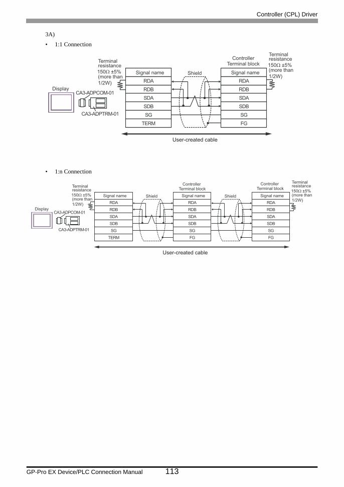
Controller (CPL) Driver
GP-Pro EX Device/PLC Connection Manual 113
3A)
• 1:1 Connection
• 1:n Connection
Signal name
RDB
SDBSG
TERM
CA3-ADPCOM-01
CA3-ADPTRM-01
Display
ShieldRDA
SDA
Signal name
RDB
SDBSGFG
RDA
SDA
150Ω ±5%(more than1/2W)
Terminalresistance Terminal block
Controller150Ω ±5%(more than1/2W)
Terminalresistance
User-created cable
Signal name
RDB
SDBSG
TERM
CA3-ADPCOM-01
CA3-ADPTRM-01
Display
ShieldRDA
SDA
Signal name
RDB
SDBSGFG
RDA
SDA
Shield Signal name
RDB
SDBSGFG
RDA
SDA
150Ω ±5%(more than1/2W)
Terminalresistance Terminal block
ControllerTerminal block
Controller
150Ω ±5%(more than1/2W)
Terminalresistance
User-created cable

Controller (CPL) Driver
GP-Pro EX Device/PLC Connection Manual 114
3B)
• 1:1 Connection
• 1:n Connection
Signal name
SDA3
RDB2
SG5
4 ERA
SDB
ERB
7
9
CSB6
FG
RDA1
CSA8
D-Sub 9 Pin (socket)
Pin
Shell
Shield Signal name
RDB
SDB
SG
FG
RDA
SDA
150Ω ±5%(more than
1/2W)
Terminalresistance Terminal block
Controller150Ω ±5%(more than
1/2W)
Terminalresistance
Display
Signal name
SDA3
RDB2
SG5
4 ERA
SDB
ERB
7
9
CSB6
FG
RDA1
CSA8
D-Sub 9 Pin (socket)
Pin
Shell
Shield Signal name
RDB
SDB
SG
FG
RDA
SDA
Shield Signal name
RDB
SDB
SG
FG
RDA
SDA
150Ω ±5%(more than
1/2W)
Terminalresistance Terminal block
ControllerTerminal block
Controller
150Ω ±5%(more than
1/2W)
Terminalresistance
Display

Controller (CPL) Driver
GP-Pro EX Device/PLC Connection Manual 115
3C)
• 1:1 Connection
• 1:n Connection
Signal name
RDB
SDBSG
TERM
CA4-ADPONL-01
CA3-ADPTRM-01
Display
ShieldRDA
SDA
Signal name
RDB
SDBSGFG
RDA
SDA
150Ω ±5%(more than1/2W)
Terminalresistance Terminal block
Controller150Ω ±5%(more than1/2W)
Terminalresistance
User-created cable
Signal name
RDB
SDBSG
TERM
CA4-ADPONL-01
CA3-ADPTRM-01
Display
ShieldRDA
SDA
Signal name
RDB
SDBSGFG
RDA
SDA
Shield Signal name
RDB
SDBSGFG
RDA
SDA
150Ω ±5%(more than1/2W)
Terminalresistance Terminal block
ControllerTerminal block
Controller
150Ω ±5%(more than1/2W)
Terminalresistance
User-created cable

Controller (CPL) Driver
GP-Pro EX Device/PLC Connection Manual 116
3D)
• 1:1 Connection
• 1:n Connection
CA4-ADPONL-01
Display
Signal name
RDB7
RDA2
SDB8
9 TERMTX
SDA
FG
3
TERMRX1
SG5
D-Sub 9 Pin (plug)Pin
Shell
Shield
RDB
SDBSGFG
RDA
SDA
150W ±5%(more than1/2W)
Terminalresistance Terminal block
Signal name
Controller150W ±5%(more than1/2W)
Terminalresistance
User-created cable
CA4-ADPONL-01
DisplayRDB7
RDA2
SDB8
9 TERMTX
SDA
FG
3
TERMRX1
SG5
Shell
Shield
RDB
SDBSGFG
RDA
SDA
Shield
RDB
SDBSGFG
RDA
SDA
150Ω ±5%(more than1/2W)
Terminalresistance Signal name
D-Sub 9 Pin (plug)Pin Terminal block
Signal name
ControllerTerminal block
Signal name
Controller150Ω ±5%(more than1/2W)
Terminalresistance
User-created cable

Controller (CPL) Driver
GP-Pro EX Device/PLC Connection Manual 117
3E)
• 1:1 Connection
• 1:n Connection
Signal name
RDB
SDBSG
TERM
CA3-ADPCOM-01
CA3-ADPTRM-01
Display
ShieldRDA
SDA
Signal name
RDB
SDBSGFG
RDA
SDA
150Ω ±5%(more than1/2W)
Terminalresistance Terminal block
Controller
(more than1/2W)
Terminalresistance150Ω ±5%
Signal name
RDB
SDBSG
TERM
RDA
SDA
Signal name
RDB
SDBSGFG
RDA
SDA
User-created cable
Signal name
RDB
SDBSG
TERM
CA3-ADPCOM-01
CA3-ADPTRM-01
Display
ShieldRDA
SDA
Signal name
RDB
SDBSGFG
RDA
SDA
Shield Signal name
RDB
SDBSGFG
RDA
SDA
150Ω ±5%(more than1/2W)
Terminalresistance Terminal block
ControllerTerminal block
Controller
150Ω ±5%(more than1/2W)
Terminalresistance
User-created cable

Controller (CPL) Driver
GP-Pro EX Device/PLC Connection Manual 118
3F)
• 1:1 Connection
• 1:n Connection
Signal name
NC3
DATA-2
GND (SG)5
NC7
ERA4
CSA8
ERB9
CSB6
FG
DATA+1
D-Sub 9 Pin (socket)
Pin
Shell
Shield Signal name
RDB
SDB
SG
FG
RDA
SDA
150Ω ±5%(more than
1/2W)
Terminalresistance Terminal block
Controller150Ω ±5%(more than
1/2W)
Terminalresistance
Display
Signal name
NC3
DATA-2
GND (SG)5
NC7
ERA4
CSA8
ERB9
CSB6
FG
DATA+1
D-Sub 9 Pin (socket)
Pin
Shell
Shield Signal name
RDB
SDB
SG
FG
RDA
SDA
Shield Signal name
RDB
SDB
SG
FG
RDA
SDA
150Ω ±5%(more than
1/2W)
Terminalresistance Terminal block
ControllerTerminal block
Controller
150Ω ±5%(more than
1/2W)
Terminalresistance
Display

Controller (CPL) Driver
GP-Pro EX Device/PLC Connection Manual 119
3G)
• 1:1 Connection
• 1:n Connection
*1 The resistance in the Display is used as the termination resistance. Set the value of the DIP Switch on the rear of the Display as shown in the table below.
DIP Switch No. Set Value
1 OFF
2 OFF
3 ON
4 ON
Signal name
SDARDB
SGERA
SDB
ERBCSB
RDA
CSA
Shield Signal name
RDB
SDBSGFG
RDA
SDA
Terminalresistance*1
Terminal blockController
150Ω ±5%(more than1/2W)
Terminalresistance
Display
Display side Terminal block
Signal name
SDARDB
SGERA
SDB
ERBCSB
RDA
CSA
Shield Signal name
RDB
SDBSGFG
RDA
SDA
Shield Signal name
RDB
SDBSGFG
RDA
SDA
Terminal blockController
Terminal blockController
150Ω ±5%(more than1/2W)
Terminalresistance
Display
Terminalresistance*1
Display side Terminal block

Controller (CPL) Driver
GP-Pro EX Device/PLC Connection Manual 120
3H)
• 1:1 Connection
• 1:n Connection
• The 5V output (Pin #6) on the Display is the power for the Siemens AG’s PROFIBUS connector. Do not use it for other devices.
• In COM on the GP-4107, the SG and FG terminals are isolated.
Shield Signal name
RDB
SDBSGFG
RDA
SDA
150Ω ±5%(more than1/2W)
Terminalresistance Terminal block
Controller150Ω ±5%(more than1/2W)
Terminalresistance
Display
Pin Signal name
NC
NC
GND(SG)
RS(RTS)
5V
NC
NC
FG
LINE(+)
LINE(-)
3
8
1
2
5
4
6
7
9
Shell
Display sideD-Sub 9pin (plug)
Shield Signal name
RDB
SDBSGFG
RDA
SDA
Shield Signal name
RDB
SDBSGFG
RDA
SDA
150Ω ±5%(more than1/2W)
Terminalresistance Terminal block
ControllerTerminal block
Controller150Ω ±5%(more than1/2W)
Terminalresistance
Display
Pin Signal name
NC
NC
GND(SG)
RS(RTS)
5V
NC
NC
FG
LINE(+)
LINE(-)
3
8
1
2
5
4
6
7
9
Shell
Display sideD-Sub 9pin (plug)

Controller (CPL) Driver
GP-Pro EX Device/PLC Connection Manual 121
3I)
• 1:1 Connection
• 1:n Connection
Signal name
RDB
SDB SG
TERM
PFXZCBADTM1
Display
Shield RDA
SDA
Signal name
RDB
SDB SG FG
RDA
SDA
150Ω ±5% (more than 1/2W)
T erminal resistance T erminal block
Controller 150Ω ±5% (more than 1/2W)
T erminal resistance
User-created cable
Signal name
RDB
SDB SG
TERM
PFXZCBADTM1
Display
Shield RDA
SDA
Signal name
RDB
SDB SG FG
RDA
SDA
Shield Signal name
RDB
SDB SG FG
RDA
SDA
150Ω ±5% (more than 1/2W)
T e rminal resistance T erminal block
Controller T erminal block
Controller
150Ω ±5% (more than 1/2W)
T e rminal resistance
User-created cable

Controller (CPL) Driver
GP-Pro EX Device/PLC Connection Manual 122
3J)
• 1:1 Connection
• 1:n Connection
Number Name Notes
(1)RJ45 RS-485 Cable (5m) by Pro-face
PFXZLMCBRJR81
Signal name
RDB
SDBSGFG
RDA
SDA
Terminal blockController
150Ω ±5%(more than1/2W)
Terminalresistance
Display
GND
D0
D1
(1)
Signal name
RDB
SDBSGFG
RDA
SDA
Shield Signal name
RDB
SDBSGFG
RDA
SDA
220Ω (1/4W)Terminal resistance Terminal block
ControllerTerminal block
Controller
220Ω (1/4W)
Terminalresistance
Display
GND
D0
D1
(1)
User-created Cable

Controller (CPL) Driver
GP-Pro EX Device/PLC Connection Manual 123
Cable Diagram 4
Display(Connection Port)
Cable Remarks
GP3000*1 (COM1)AGP-3302B (COM2)GP-4*01TM (COM1)ST*2 (COM2)LT3000 (COM1)
*1 All GP3000 models except AGP-3302B
*2 All ST models except AST-3211A and AST-3302B
4A
COM port conversion adapter by Pro-face.CA3-ADPCOM-01
+Connector terminal block conversion adapter by Pro-face
CA3-ADPTRM-01+
User-created cable
Cable length:500m or less
4B User-created cable
GP3000*3 (COM2)
*3 All GP3000 models except the GP-3200 Series and AGP-3302B
4C
Online adapter by Pro-faceCA4-ADPONL-01
+Connector terminal block conversion adapter by Pro-face
CA3-ADPTRM-01+
User-created cable
4D
Online adapter by Pro-faceCA4-ADPONL-01
+User-created cable
IPC*4
*4 Available only with COM ports that support RS-422/485 (2wire). IPC COM Port (page 9)
4E
COM port conversion adapter by Pro-face.CA3-ADPCOM-01
+Connector terminal block conversion adapter by Pro-face
CA3-ADPTRM-01+
User-created cable4F User-created cable
GP-4106 (COM1) 4G User-created cableGP-4107 (COM1)GP-4*03T*5 (COM2)GP-4203T (COM1)
*5 Except GP-4203T
4H User-created cable
GP4000*6 (COM2)GP-4201T (COM1)
*6 All GP4000 models except GP-4100 series, GP-4*01TM, GP-4201T and GP-4*03T
4I
RS-422 terminal block conversion adapter by Pro-facePFXZCBADTM1*7
+User-created cable
*7 When using a Terminal Block Conversion Adapter (CA3-ADPTRM-01) instead of the RS-422 Terminal BlockConversion Adapter, refer to Cable Diagram 4A.
4B User-created cable
LT-4*01TM (COM1) 4JRJ45 RS-485 Cable (5m) by Pro-face
PFXZLMCBRJR81

Controller (CPL) Driver
GP-Pro EX Device/PLC Connection Manual 124
4A)
• 1:1 Connection
• 1:n Connection
• No termination resistor is required.
• No termination resistor is required.
Signal name
RDB
SDBSG
TERM
CA3-ADPCOM-01
CA3-ADPTRM-01
Display
ShieldRDA
SDA DA
DB
SG
Terminal blockSignal name
Controller
User-created cable
Signal name
RDB
SDBSG
TERM
CA3-ADPCOM-01
CA3-ADPTRM-01
Display
ShieldRDA
SDA DA
DB
SG
Shield
DA
DB
SG
Terminal blockSignal name
ControllerTerminal block
Signal name
Controller
User-created cable

Controller (CPL) Driver
GP-Pro EX Device/PLC Connection Manual 125
4B)
• 1:1 Connection
• 1:n Connection
• No termination resistor is required.
• No termination resistor is required.
Signal name
SDA3
RDB2
SG5
4 ERA
SDB
ERB
7
9
CSB6
FG
RDA1
CSA8
D-Sub 9 Pin (socket)
Pin
Shell
Shield
DA
DB
SG
Terminal block
Signal name
Controller
Display
SDA3
RDB2
SG5
4 ERA
SDB
ERB
7
9
CSB6
FG
RDA1
CSA8
D-Sub 9 Pin (socket)
Shell
Shield
DA
DB
SG
Shield
DA
DB
SG
Signal namePin
Terminal block
Signal name
Controller
Terminal block
Signal name
Controller
Display

Controller (CPL) Driver
GP-Pro EX Device/PLC Connection Manual 126
4C)
• 1:1 Connection
• 1:n Connection
• No termination resistor is required.
• No termination resistor is required.
Signal name
RDB
SDBSG
TERM
CA4-ADPONL-01
CA3-ADPTRM-01
Display
ShieldRDA
SDA DA
DB
SG
Terminal blockSignal name
Controller
User-created cable
Signal name
RDB
SDBSG
TERM
CA4-ADPONL-01
CA3-ADPTRM-01
Display
ShieldRDA
SDA DA
DB
SG
Shield
DA
DB
SG
Terminal blockSignal name
ControllerTerminal block
Signal name
Controller
User-created cable
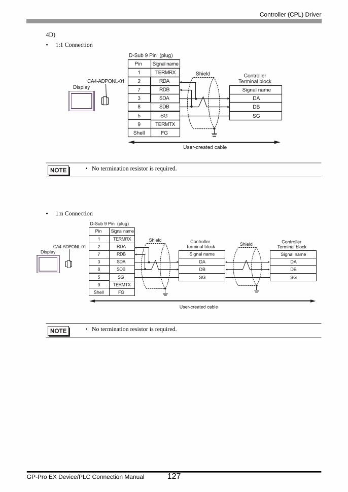
Controller (CPL) Driver
GP-Pro EX Device/PLC Connection Manual 127
4D)
• 1:1 Connection
• 1:n Connection
• No termination resistor is required.
• No termination resistor is required.
CA4-ADPONL-01Display RDB7
RDA2
SDB8
9 TERMTX
SDA
FG
3
TERMRX1
SG5
D-Sub 9 Pin (plug)
Shell
Shield
DA
DB
SG
Signal namePin
Terminal blockSignal name
Controller
User-created cable
CA4-ADPONL-01Display RDB7
RDA2
SDB8
9 TERMTX
SDA
FG
3
TERMRX1
SG5
Shell
Shield
DA
DB
SG
Shield
DA
DB
SG
Signal nameD-Sub 9 Pin (plug)
Pin
Terminal blockSignal name
ControllerTerminal block
Signal name
Controller
User-created cable

Controller (CPL) Driver
GP-Pro EX Device/PLC Connection Manual 128
4E)
• 1:1 Connection
• 1:n Connection
• No termination resistor is required.
• No termination resistor is required.
Signal name
RDB
SDBSG
TERM
CA3-ADPCOM-01
CA3-ADPTRM-01
Display
ShieldRDA
SDA
DA
DB
SG
Terminal blockSignal name
Controller
User-created cable
Signal name
RDB
SDBSG
TERM
CA3-ADPCOM-01
CA3-ADPTRM-01
Display
ShieldRDA
SDA
DA
DB
SG
Shield
DA
DB
SG
Terminal blockSignal name
ControllerTerminal block
Signal name
Controller
User-created cable

Controller (CPL) Driver
GP-Pro EX Device/PLC Connection Manual 129
4F)
• 1:1 Connection
• 1:n Connection
• No termination resistor is required.
• No termination resistor is required.
Signal name
NC3
DATA-2
5
NC7
ERA4
CSA8
FG
DATA+1
D-Sub 9 Pin (socket)
Pin
Shell
Shield
DA
DB
SG
Terminal block
Signal name
Controller
Display
ERB9
CSB6
GND (SG)
NC3
DATA-2
GND (SG)5NC7
ERA4CSA8ERB9CSB6FG
DATA+1
D-Sub 9 Pin (socket)
Shell
ShieldDA
DB
SG
Shield
DA
DB
SG
Signal namePin
Terminal blockSignal name
ControllerTerminal block
Signal name
Controller
Display

Controller (CPL) Driver
GP-Pro EX Device/PLC Connection Manual 130
4G)
• 1:1 Connection
• 1:n Connection
• No termination resistor is required.
• No termination resistor is required.
Signal name
SDARDB
SGERA
SDB
ERBCSB
RDA
CSA
Shield
DA
DB
SG
Terminal blockSignal name
Controller
Display
Display side Terminal block
SDARDB
SGERA
SDB
ERBCSB
RDA
CSA
Shield
DA
DB
SG
Shield
DA
DB
SG
Signal nameTerminal block
Signal name
ControllerTerminal block
Signal name
Controller
Display
Display side Terminal block

Controller (CPL) Driver
GP-Pro EX Device/PLC Connection Manual 131
4H)
• 1:1 Connection
• 1:n Connection
• No termination resistor is required.
• The 5V output (Pin #6) on the Display is the power for the Siemens AG’s PROFIBUS connector. Do not use it for other devices.
• No termination resistor is required.• In COM on the GP-4107, the SG and FG terminals are isolated.
ShieldDA
DB
SG
Terminal blockSignal name
Controller
Display
Pin Signal name
NC
NC
GND(SG)
RS(RTS)
5V
NC
NC
FG
LINE(+)
LINE(-)
3
8
1
2
5
4
6
7
9
Shell
Display sideD-Sub 9pin (plug)
ShieldDA
DB
SG
Shield
DA
DB
SG
Terminal blockSignal name
ControllerTerminal block
Signal name
Controller
Display
Pin Signal name
NC
NC
GND(SG)
RS(RTS)
5V
NC
NC
FG
LINE(+)
LINE(-)
3
8
1
2
5
4
6
7
9
Shell
Display sideD-Sub 9pin (plug)

Controller (CPL) Driver
GP-Pro EX Device/PLC Connection Manual 132
4I)
• 1:1 Connection
• 1:n Connection
• No termination resistor is required.
• No termination resistor is required.
Signal name
RDB
SDB SG
TERM
PFXZCBADTM1
Display
Shield RDA
SDA DA
DB
SG
Terminal block Signal name
Controller
User-created cable
Signal name
RDB
SDB SG
TERM
PFXZCBADTM1
Display
Shield RDA
SDA DA
DB
SG
Shield
DA
DB
SG
Terminal block Signal name
Controller Terminal block
Signal name
Controller
User-created cable

Controller (CPL) Driver
GP-Pro EX Device/PLC Connection Manual 133
4J)
• 1:1 Connection
• 1:n Connection
• No termination resistor is required.
• No termination resistor is required.
Number Name Notes
(1)RJ45 RS-485 Cable (5m) by Pro-face
PFXZLMCBRJR81
DA
DB
SG
Terminal blockSignal name
Controller
Display
GNDD0
D1
(1)
DA
DB
SG
Sh i e l d
DA
DB
SG
T erm i na l b l ock S i gna l name
Contro ll er T erm i na l b l ock
S i gna l name
Contro ll er
Display
GNDD0
D1
(1)
User-created Cable

Controller (CPL) Driver
GP-Pro EX Device/PLC Connection Manual 134
Cable Diagram 5
Display(Connection Port)
Cable Remarks
GP3000*1 (COM1)AGP-3302B (COM2)GP-4*01TM (COM1)ST*2 (COM2)LT3000 (COM1)
*1 All GP3000 models except AGP-3302B
*2 All ST models except AST-3211A and AST-3302B
5A
COM port conversion adapter by Pro-face.CA3-ADPCOM-01
+Connector terminal block conversion adapter by Pro-face
CA3-ADPTRM-01+
User-created cable
Cable length:500m or less
5B User-created cable
GP3000*3 (COM2)
*3 All GP3000 models except the GP-3200 Series and AGP-3302B
5C
Online adapter by Pro-faceCA4-ADPONL-01
+Connector terminal block conversion adapter by Pro-face
CA3-ADPTRM-01+
User-created cable
5D
Online adapter by Pro-faceCA4-ADPONL-01
+User-created cable
IPC*4
*4 Available only with COM ports that support RS-422/485 (2wire). IPC COM Port (page 9)
5E
COM port conversion adapter by Pro-face.CA3-ADPCOM-01
+Connector terminal block conversion adapter by Pro-face
CA3-ADPTRM-01+
User-created cable5F User-created cable
GP-4106 (COM1) 5G User-created cableGP-4107 (COM1)GP-4*03T*5 (COM2)GP-4203T (COM1)
*5 Except GP-4203T
5H User-created cable
GP4000*6 (COM2)GP-4201T (COM1)
*6 All GP4000 models except GP-4100 series, GP-4*01TM, GP-4201T and GP-4*03T
5I
RS-422 terminal block conversion adapter by Pro-facePFXZCBADTM1*7
+User-created cable
*7 When using a Terminal Block Conversion Adapter (CA3-ADPTRM-01) instead of the RS-422 Terminal BlockConversion Adapter, refer to Cable Diagram 5A.
5B User-created cable
LT-4*01TM (COM1) 5JRJ45 RS-485 Cable (5m) by Pro-face
PFXZLMCBRJR81

Controller (CPL) Driver
GP-Pro EX Device/PLC Connection Manual 135
5A)
• 1:1 Connection
• 1:n Connection
Signal name
RDB
SDBSG
TERM
CA3-ADPCOM-01
CA3-ADPTRM-01
Display
ShieldRDA
SDA
SG
-+
FG
150Ω ±5%(more than1/2W)
Terminalresistance
150Ω ±5%(more than1/2W)
Terminalresistance
Terminal blockSignal name
Controller
User-created cable
Signal name
RDB
SDBSG
TERM
CA3-ADPCOM-01
CA3-ADPTRM-01
Display
ShieldRDA
SDA
SGFG
Shield
SG
-+
-+
FG
150Ω ±5%(more than1/2W)
Terminalresistance
Terminal blockSignal name
ControllerTerminal block
Signal name
Controller150Ω ±5%(more than1/2W)
Terminalresistance
User-created cable

Controller (CPL) Driver
GP-Pro EX Device/PLC Connection Manual 136
5B)
• 1:1 Connection
• 1:n Connection
SDA3
RDB2
SG5
4 ERA
SDB
ERB
7
9
CSB6
FG
RDA1
CSA8
Shield
SG
-
+
FG
Signal name
D-Sub 9 Pin (socket)
Pin
Shell
Terminal block
Signal name
Controller150Ω ±5%(more than
1/2W)
Terminalresistance
150Ω ±5%(more than
1/2W)
Terminalresistance
Display
SDA3
RDB2
SG5
4 ERA
SDB
ERB
7
9
CSB6
FG
RDA1
CSA8
Shield
SG
FG
Shield
SG
-
+
-
+
FG
Signal name
D-Sub 9 Pin (socket)
Pin
Shell
150Ω ±5%(more than
1/2W)
Terminalresistance
Terminal block
Signal name
ControllerTerminal block
Signal name
Controller
150Ω ±5%(more than
1/2W)
Terminalresistance
Display

Controller (CPL) Driver
GP-Pro EX Device/PLC Connection Manual 137
5C)
• 1:1 Connection
• 1:n Connection
Signal name
RDB
SDBSG
TERM
CA4-ADPONL-01
CA3-ADPTRM-01
Display
ShieldRDA
SDA
SG-+
FG
150Ω ±5%(more than1/2W)
Terminalresistance
Terminal blockSignal name
Controller150Ω ±5%(more than1/2W)
Terminalresistance
User-created cable
Signal name
RDB
SDBSG
TERM
CA4-ADPONL-01
CA3-ADPTRM-01
Display
ShieldRDA
SDA
SGFG
Shield
SG
-+
-+
FG
150Ω ±5%(more than1/2W)
Terminalresistance
Terminal blockSignal name
ControllerTerminal block
Signal name
Controller150Ω ±5%(more than1/2W)
Terminalresistance
User-created cable

Controller (CPL) Driver
GP-Pro EX Device/PLC Connection Manual 138
5D)
• 1:1 Connection
• 1:n Connection
CA4-ADPONL-01
DisplayRDB7
RDA2
SDB8
9 TERMTX
SDA
FG
3
TERMRX1
SG5
Shield
SG-+
FG
150Ω ±5%(more than1/2W)
Terminalresistance Signal name
D-Sub 9 Pin (plug)Pin
Shell
Terminal blockSignal name
150Ω ±5%(more than1/2W)
TerminalresistanceController
User-created cable
CA4-ADPONL-01
DisplayRDB7
RDA2
SDB8
9 TERMTX
SDA
FG
3
TERMRX1
SG5
Shield
SGFG
Shield
SG-+
-+
FG
Signal nameD-Sub 9 Pin (plug)
Pin
Shell
Terminal blockSignal name
ControllerTerminal block
Signal name
Controller150Ω ±5%(more than1/2W)
Terminalresistance
150Ω ±5%(more than1/2W)
Terminalresistance
User-created cable

Controller (CPL) Driver
GP-Pro EX Device/PLC Connection Manual 139
5E)
• 1:1 Connection
• 1:n Connection
Signal name
RDB
SDBSG
TERM
CA3-ADPCOM-01
CA3-ADPTRM-01
Display
ShieldRDA
SDA SG-+
FG
150Ω ±5%(more than1/2W)
Terminalresistance 150Ω ±5%
(more than1/2W)
Terminalresistance
Terminal blockSignal name
Controller
User-created cable
Signal name
RDB
SDBSG
TERM
CA3-ADPCOM-01
CA3-ADPTRM-01
Display
ShieldRDA
SDA SGFG
Shield
SG
-+
-+
FG
150Ω ±5%(more than1/2W)
Terminalresistance Terminal block
Signal name
ControllerTerminal block
Signal name
Controller150Ω ±5%(more than1/2W)
Terminalresistance
User-created cable

Controller (CPL) Driver
GP-Pro EX Device/PLC Connection Manual 140
5F)
• 1:1 Connection
• 1:n Connection
NC3
DATA-2
GND (SG)5
NC7
ERA4
CSA8
ERB9
CSB6
FG
DATA+1
Shield
SG
-
+
FG
Signal name
D-Sub 9 Pin (socket)
Pin
Shell
Terminal block
Signal name
Controller
150Ω ±5%(more than
1/2W)
Terminalresistance 150Ω ±5%
(more than
1/2W)
Terminalresistance
Display
NC3
DATA-2
GND (SG)5
NC7
ERA4
CSA8
FG
DATA+1
Shield
SG
FG
Shield
SG
-
+
-
+
FG
Signal name
D-Sub 9 Pin (socket)
Pin
Shell
150Ω ±5%(more than1/2W)
Terminalresistance
Terminal block
Signal name
ControllerTerminal block
Signal name
Controller
150Ω ±5%(more than1/2W)
Terminalresistance
Display
ERB9
CSB6

Controller (CPL) Driver
GP-Pro EX Device/PLC Connection Manual 141
5G)
• 1:1 Connection
• 1:n Connection
*1 The resistance in the Display is used as the termination resistance. Set the value of the DIP Switch on the rear of the Display as shown in the table below.
DIP Switch No. Set Value
1 OFF
2 OFF
3 ON
4 ON
SDARDB
SGERA
SDB
ERBCSB
RDA
CSA
Shield
SG
-+
FG
Signal name
Terminal blockSignal name
ControllerTerminalresistance*1
150Ω ±5%(more than1/2W)
Terminalresistance
Display
Display side Terminal block
SDARDB
SGERA
SDB
ERBCSB
RDA
CSA
Shield
SGFG
Shield
SG-+
-+
FG
Signal nameTerminalresistance*1
Terminal blockSignal name
ControllerTerminal block
Signal name
Controller
150Ω ±5%(more than1/2W)
Terminalresistance
Display
Display side Terminal block

Controller (CPL) Driver
GP-Pro EX Device/PLC Connection Manual 142
5H)
• 1:1 Connection
• 1:n Connection
• The 5V output (Pin #6) on the Display is the power for the Siemens AG’s PROFIBUS connector. Do not use it for other devices.
• In COM on the GP-4107, the SG and FG terminals are isolated.
Shield
SG-+
FG
Terminal blockSignal name
Controller
150Ω ±5%(more than1/2W)
Terminalresistance 150Ω ±5%
(more than1/2W)
Terminalresistance
Display
Pin Signal name
NC
NC
GND(SG)
RS(RTS)
5V
NC
NC
FG
LINE(+)
LINE(-)
3
8
1
2
5
4
6
7
9
Shell
Display sideD-Sub 9pin (plug)
Shield
SGFG
Shield
SG
-+
-+
FG
150Ω ±5%(more than1/2W)
Terminalresistance Terminal block
Signal name
ControllerTerminal block
Signal name
Controller150Ω ±5%(more than1/2W)
Terminalresistance
Display
Pin Signal name
NC
NC
GND(SG)
RS(RTS)
5V
NC
NC
FG
LINE(+)
LINE(-)
3
8
1
2
5
4
6
7
9
Shell
Display sideD-Sub 9pin (plug)

Controller (CPL) Driver
GP-Pro EX Device/PLC Connection Manual 143
5I)
• 1:1 Connection
• 1:n Connection
Signal name
RDB
SDB SG
TERM
PFXZCBADTM1
Display
Shield RDA
SDA
SG
- +
FG
150Ω ±5% (more than 1/2W)
T erminal resistance
150Ω ±5% (more than 1/2W)
T e rminal resistance
T erminal block Signal name
Controller
User-created cable
Signal name
RDB
SDB SG
TERM
PFXZCBADTM1
Display
Shield RDA
SDA
SG FG
Shield
SG
- +
- +
FG
150Ω ±5% (more than 1/2W)
T e rminal resistance
T e rminal block Signal name
Controller T e rminal block
Signal name
Controller 150Ω ±5% (more than 1/2W)
T erminal resistance
User-created cable

Controller (CPL) Driver
GP-Pro EX Device/PLC Connection Manual 144
5J)
• 1:1 Connection
• 1:n Connection
Number Name Notes
(1)RJ45 RS-485 Cable (5m) by Pro-face
PFXZLMCBRJR81
SG-+
FG
Terminal blockSignal name
Controller150Ω ±5%(more than1/2W)
Terminalresistance
Display
GNDD0
D1
(1)
SGFG
Shield
SG
-+
-+
FG
220Ω (1/4W)Terminal resistance Terminal block
Signal name
ControllerTerminal block
Signal name
Controller
220Ω (1/4W)
Terminalresistance
Display
GNDD0
D1
(1)
User-created Cable

Controller (CPL) Driver
GP-Pro EX Device/PLC Connection Manual 145
Cable Diagram 6
Display(Connection Port)
Cable Remarks
GP3000*1 (COM1)AGP-3302B (COM2)GP-4*01TM (COM1)ST*2 (COM2)LT3000 (COM1)
*1 All GP3000 models except AGP-3302B
*2 All ST models except AST-3211A and AST-3302B
6A
COM port conversion adapter by Pro-face.CA3-ADPCOM-01
+Connector terminal block conversion adapter by Pro-face
CA3-ADPTRM-01+
User-created cable
Cable length:500m or less
6B User-created cable
GP3000*3 (COM2)
*3 All GP3000 models except the GP-3200 Series and AGP-3302B
6C
Online adapter by Pro-faceCA4-ADPONL-01
+Connector terminal block conversion adapter by Pro-face
CA3-ADPTRM-01+
User-created cable
6D
Online adapter by Pro-faceCA4-ADPONL-01
+User-created cable
IPC*4
*4 Available only with COM ports that support RS-422/485 (2wire). IPC COM Port (page 9)
6E
COM port conversion adapter by Pro-face.CA3-ADPCOM-01
+Connector terminal block conversion adapter by Pro-face
CA3-ADPTRM-01+
User-created cable6F User-created cable
GP-4106 (COM1) 6G User-created cableGP-4107 (COM1)GP-4*03T*5 (COM2)GP-4203T (COM1)
*5 Except GP-4203T
6H User-created cable
GP4000*6 (COM2)GP-4201T (COM1)
*6 All GP4000 models except GP-4100 series, GP-4*01TM, GP-4201T and GP-4*03T
6I
RS-422 terminal block conversion adapter by Pro-facePFXZCBADTM1*7
+User-created cable
*7 When using a Terminal Block Conversion Adapter (CA3-ADPTRM-01) instead of the RS-422 Terminal BlockConversion Adapter, refer to Cable Diagram 6A.
6B User-created cable
LT-4*01TM (COM1) 6JRJ45 RS-485 Cable (5m) by Pro-face
PFXZLMCBRJR81

Controller (CPL) Driver
GP-Pro EX Device/PLC Connection Manual 146
6A)
• 1:1 Connection
• 1:n Connection
• No termination resistor is required.
• No termination resistor is required.
Signal name
RDB
SDBSG
TERM
CA3-ADPCOM-01
CA3-ADPTRM-01
Display
ShieldRDA
SDA DA
DBSGFG
Terminal blockSignal name
Controller
User-created cable
Signal name
RDB
SDBSG
TERM
CA3-ADPCOM-01
CA3-ADPTRM-01
Display
ShieldRDA
SDA DA
DBSGFG
Shield
DA
DBSGFG
Terminal blockSignal name
ControllerTerminal block
Signal name
Controller
User-created cable

Controller (CPL) Driver
GP-Pro EX Device/PLC Connection Manual 147
6B)
• 1:1 Connection
• 1:n Connection
• No termination resistor is required.
• No termination resistor is required.
SDA3
RDB2
SG5
4 ERA
SDB
ERB
7
9
CSB6
FG
RDA1
CSA8
Shield
DA
DB
SG
FG
Signal name
D-Sub 9 Pin (socket)
Pin
Shell
Terminal block
Signal name
Controller
Display
SDA3
RDB2
SG5
4 ERA
SDB
ERB
7
9
CSB6
FG
RDA1
CSA8
Shield
DA
DB
SG
FG
Shield
DA
DB
SG
FG
Signal name
D-Sub 9 Pin (socket)
Pin
Shell
Terminal block
Signal name
Controller
Terminal block
Signal name
Controller
Display

Controller (CPL) Driver
GP-Pro EX Device/PLC Connection Manual 148
6C)
• 1:1 Connection
• 1:n Connection
• No termination resistor is required.
• No termination resistor is required.
Signal name
RDB
SDBSG
TERM
CA4-ADPONL-01
CA3-ADPTRM-01
Display
ShieldRDA
SDA DA
DBSGFG
Terminal blockSignal name
Controller
User-created cable
Signal name
RDB
SDBSG
TERM
CA4-ADPONL-01
CA3-ADPTRM-01
Display
ShieldRDA
SDA DA
DBSGFG
Shield
DA
DBSGFG
Terminal blockSignal name
ControllerTerminal block
Signal name
Controller
User-created cable

Controller (CPL) Driver
GP-Pro EX Device/PLC Connection Manual 149
6D)
• 1:1 Connection
• 1:n Connection
• No termination resistor is required.
• No termination resistor is required.
CA4-ADPONL-01
DisplayRDB7
RDA2
SDB8
9 TERMTX
SDA
FG
3
TERMRX1
SG5
Shield
DA
DBSGFG
Signal nameD-Sub 9 Pin (plug)
Pin
Shell
Terminal blockSignal name
Controller
User-created cable
CA4-ADPONL-01
DisplayRDB7
RDA2
SDB8
9 TERMTX
SDA
FG
3
TERMRX1
SG5
Shield
DA
DBSGFG
Shield
DA
DBSGFG
Signal nameD-Sub 9 Pin (plug)
Pin
Shell
Terminal blockSignal name
ControllerTerminal block
Signal name
Controller
User-created cable

Controller (CPL) Driver
GP-Pro EX Device/PLC Connection Manual 150
6E)
• 1:1 Connection
• 1:n Connection
• No termination resistor is required.
• No termination resistor is required.
Signal name
RDB
SDBSG
TERM
CA3-ADPCOM-01
CA3-ADPTRM-01
Display
ShieldRDA
SDA
DA
DBSGFG
Terminal blockSignal name
Controller
User-created cable
Signal name
RDB
SDBSG
TERM
CA3-ADPCOM-01
CA3-ADPTRM-01
Display
ShieldRDA
SDA
DA
DBSGFG
Shield
DA
DBSGFG
Terminal blockSignal name
ControllerTerminal block
Signal name
Controller
User-created cable

Controller (CPL) Driver
GP-Pro EX Device/PLC Connection Manual 151
6F)
• 1:1 Connection
• 1:n Connection
• No termination resistor is required.
• No termination resistor is required.
NC3
DATA-2
GND (SG)5
NC7
ERA4
CSA8
FG
DATA+1
Shield
DA
DB
SG
FG
Signal name
D-Sub 9 Pin (socket)
Pin
Shell
Terminal block
Signal name
Controller
Display
ERB9
CSB6
NC3
DATA-2
GND (SG)5
NC7
ERA4
CSA8
FG
DATA+1
Shield
DA
DB
SG
FG
Shield
DA
DB
SG
FG
Signal name
D-Sub 9 Pin (socket)
Pin
Shell
Terminal block
Signal name
ControllerTerminal block
Signal name
Controller
Display
ERB9
CSB6

Controller (CPL) Driver
GP-Pro EX Device/PLC Connection Manual 152
6G)
• 1:1 Connection
• 1:n Connection
• No termination resistor is required.
• No termination resistor is required.
SDARDB
SGERA
SDB
ERBCSB
RDA
CSA
Shield
DA
DBSGFG
Signal name
Terminal blockSignal name
Controller
Display
Display side Terminal block
SDARDB
SGERA
SDB
ERBCSB
RDA
CSA
Shield
DA
DBSGFG
Shield
DA
DBSGFG
Signal name
Terminal blockSignal name
ControllerTerminal block
Signal name
Controller
Display
Display side Terminal block

Controller (CPL) Driver
GP-Pro EX Device/PLC Connection Manual 153
6H)
• 1:1 Connection
• 1:n Connection
• No termination resistor is required.
• The 5V output (Pin #6) on the Display is the power for the Siemens AG’s PROFIBUS connector. Do not use it for other devices.
• No termination resistor is required.• In COM on the GP-4107, the SG and FG terminals are isolated.
ShieldDA
DBSGFG
Terminal blockSignal name
Controller
Display
Pin Signal name
NC
NC
GND(SG)
RS(RTS)
5V
NC
NC
FG
LINE(+)
LINE(-)
3
8
1
2
5
4
6
7
9
Shell
Display sideD-Sub 9pin (plug)
ShieldDA
DBSGFG
Shield
DA
DBSGFG
Terminal blockSignal name
ControllerTerminal block
Signal name
Controller
Display
Pin Signal name
NC
NC
GND(SG)
RS(RTS)
5V
NC
NC
FG
LINE(+)
LINE(-)
3
8
1
2
5
4
6
7
9
Shell
Display sideD-Sub 9pin (plug)

Controller (CPL) Driver
GP-Pro EX Device/PLC Connection Manual 154
6I)
• 1:1 Connection
• 1:n Connection
• No termination resistor is required.
• No termination resistor is required.
Signal name
RDB
SDB SG
TERM
PFXZCBADTM1
Display
Shield RDA
SDA DA
DB SG FG
Terminal block Signal name
Controller
User-created cable
Signal name
RDB
SDB SG
TERM
PFXZCBADTM1
Display
Shield RDA
SDA DA
DB SG FG
Shield
DA
DB SG FG
Terminal block Signal name
Controller Terminal block
Signal name
Controller
User-created cable

Controller (CPL) Driver
GP-Pro EX Device/PLC Connection Manual 155
6J)
• 1:1 Connection
• 1:n Connection
• No termination resistor is required.
• No termination resistor is required.
Number Name Notes
(1)RJ45 RS-485 Cable (5m) by Pro-face
PFXZLMCBRJR81
DA
DBSGFG
Terminal blockSignal name
Controller
Display
GNDD0
D1
(1)
DA
DBSGFG
Shield
DA
DBSGFG
Terminal blockSignal name
ControllerTerminal block
Signal name
Controller
Display
GNDD0
D1
(1)
User-created Cable

Controller (CPL) Driver
GP-Pro EX Device/PLC Connection Manual 156
Cable Diagram 7
Display(Connection Port)
Cable Remarks
GP3000*1 (COM1)AGP-3302B (COM2)GP-4*01TM (COM1)ST*2 (COM2)LT3000 (COM1)IPC*3
*1 All GP3000 models except AGP-3302B
*2 All ST models except AST-3211A and AST-3302B
*3 Available only with COM ports that support RS-422/485 (4wire). IPC COM Port (page 9)
7A
COM port conversion adapter by Pro-face.CA3-ADPCOM-01
+Connector terminal block conversion adapter by Pro-face
CA3-ADPTRM-01+
User-created cable
Cable length: 500m or less
7B User-created cable
GP3000*4 (COM2)
*4 All GP3000 models except the GP-3200 Series and AGP-3302B
7C
Online adapter by Pro-faceCA4-ADPONL-01
+Connector terminal block conversion adapter by Pro-face
CA3-ADPTRM-01+
User-created cable
7D
Online adapter by Pro-faceCA4-ADPONL-01
+User-created cable
GP-4106 (COM1) 7E User-created cable
GP4000*5 (COM2)GP-4201T (COM1)
*5 All GP4000 models except GP-4100 series, GP-4*01TM, GP-4201T and GP-4*03T
7F
RS-422 terminal block conversion adapter by Pro-facePFXZCBADTM1*6
+User-created cable
*6 When using a Terminal Block Conversion Adapter (CA3-ADPTRM-01) instead of the RS-422 Terminal BlockConversion Adapter, refer to Cable Diagram 7A.
7B User-created cable

Controller (CPL) Driver
GP-Pro EX Device/PLC Connection Manual 157
7A
• 1:1 Connection
• 1:n Connection
Signal name
RDB
SDBSGFG
CA3-ADPCOM-01
CA3-ADPTRM-01
Display
Terminal blockShield
Connector for the host sidecommunication connection
RDA
SDA
Signal name
RDB
SDB
SG
RDA
SDAPin
14
12
15
13
11
User-created cable
Signal name
RDB
SDBSGFG
CA3-ADPCOM-01
CA3-ADPTRM-01
Display
Terminal blockShield
Connector for the host sidecommunication connection
RDA
SDA
Shield
Connector for the host sidecommunication connection
Signal name
RDB
SDB
SG
RDA
SDAPin
14
12
15
13
11Signal name
RDB
SDB
SG
RDA
SDAPin
14
12
15
13
11
User-created cable

Controller (CPL) Driver
GP-Pro EX Device/PLC Connection Manual 158
7B)
• 1:1 Connection
• 1:n Connection
Signal name
SDA3
RDB2
SG5
4 ERA
SDB
ERB
7
9
CSB6
FG
RDA1
CSA8
D-Sub 9 pin (socket)
Pin
Shell
Display
Shield
Connector for the host side
communication connection
Signal name
RDB
SDB
SG
RDA
SDA
Pin
14
12
15
13
11
Signal name
SDA3
RDB2
SG5
4 ERA
SDB
ERB
7
9
CSB6
FG
RDA1
CSA8
D-Sub 9 pin (socket)
Pin
Shell
Display
Shield
Connector for the host side
communication connection
Shield
Connector for the host side
communication connection
Signal name
RDB
SDB
SG
RDA
SDA
Pin
14
12
15
13
11
Signal name
RDB
SDB
SG
RDA
SDA
Pin
14
12
15
13
11

Controller (CPL) Driver
GP-Pro EX Device/PLC Connection Manual 159
7C)
• 1:1 Connection
• 1:n Connection
Signal name
RDB
SDBSGFG
CA4-ADPONL-01
CA3-ADPTRM-01
Display
Terminal blockShield
Connector for the host sidecommunication connection
RDA
SDA
Signal name
RDB
SDB
SG
RDA
SDAPin
14
12
15
13
11
User-created cable
Signal name
RDB
SDBSGFG
CA4-ADPONL-01
CA3-ADPTRM-01
Display
Terminal blockShield
Connector for the host sidecommunication connection
RDA
SDA
Shield
Connector for the host sidecommunication connection
Signal name
RDB
SDB
SG
RDA
SDAPin
14
12
15
13
11Signal name
RDB
SDB
SG
RDA
SDAPin
14
12
15
13
11
User-created cable

Controller (CPL) Driver
GP-Pro EX Device/PLC Connection Manual 160
7D)
• 1:1 Connection
• 1:n Connection
CA4-ADPONL-01
Display
Signal name
RDB7
RDA2
SDB8
9 TERMTX
SDA
FG
3
TERMRX1
SG5
D-Sub 9 pin (plug)Pin
Shell
Shield
Connector for the host sidecommunication connection
Signal name
RDB
SDB
SG
RDA
SDAPin
14
12
15
13
11
User-created cable
CA4-ADPONL-01
Display
Signal name
RDB7
RDA2
SDB8
9 TERMTX
SDA
FG
3
TERMRX1
SG5
D-Sub 9 pin (plug)Pin
Shell
Shield
Connector for the host sidecommunication connection
Shield
Connector for the host sidecommunication connection
Signal name
RDB
SDB
SG
RDA
SDAPin
14
12
15
13
11Signal name
RDB
SDB
SG
RDA
SDAPin
14
12
15
13
11
User-created cable

Controller (CPL) Driver
GP-Pro EX Device/PLC Connection Manual 161
7E)
• 1:1 Connection
• 1:n Connection
Signal name
SDARDB
SGERA
SDB
ERBCSB
RDA
CSA
Display
Shield
Connector for the host sidecommunication connection
Signal name
RDB
SDB
SG
RDA
SDAPin
14
12
15
13
11
Display side Terminal block
Signal name
SDARDB
SGERA
SDB
ERBCSB
RDA
CSA
Display
Shield
Connector for the host sidecommunication connection
Shield
Connector for the host sidecommunication connection
Signal name
RDB
SDB
SG
RDA
SDAPin
14
12
15
13
11Signal name
RDB
SDB
SG
RDA
SDAPin
14
12
15
13
11
Display side Terminal block

Controller (CPL) Driver
GP-Pro EX Device/PLC Connection Manual 162
7F
• 1:1 Connection
• 1:n Connection
Signal name
RDB
SDB SG FG
PFXZCBADTM1
Display
Terminal block Shield
Connector for the host side communication connection
RDA
SDA
Signal name
RDB
SDB
SG
RDA
SDA Pin
14
12
15
13
11
User-created cable
Signal name
RDB
SDB SG FG
PFXZCBADTM1
Display
Terminal block Shield
Connector for the host side communication connection
RDA
SDA
Shield
Connector for the host side communication connection
Signal name
RDB
SDB
SG
RDA
SDA Pin
14
12
15
13
11 Signal name
RDB
SDB
SG
RDA
SDA Pin
14
12
15
13
11
User-created cable

Controller (CPL) Driver
GP-Pro EX Device/PLC Connection Manual 163
Cable Diagram 8
Display(Connection Port)
Cable Remarks
GP3000*1 (COM1)AGP-3302B (COM2)GP-4*01TM (COM1)ST*2 (COM2)LT3000 (COM1)
*1 All GP3000 models except AGP-3302B
*2 All ST models except AST-3211A and AST-3302B
8A
COM port conversion adapter by Pro-face.CA3-ADPCOM-01
+Connector terminal block conversion adapter by Pro-face
CA3-ADPTRM-01+
User-created cable
Cable length: 500m or less
8B User-created cable
GP3000*3 (COM2)
*3 All GP3000 models except the GP-3200 Series and AGP-3302B
8C
Online adapter by Pro-faceCA4-ADPONL-01
+Connector terminal block conversion adapter by Pro-face
CA3-ADPTRM-01+
User-created cable
8D
Online adapter by Pro-faceCA4-ADPONL-01
+User-created cable
IPC*4
*4 Available only with COM ports that support RS-422/485 (2wire). IPC COM Port (page 9)
8E
COM port conversion adapter by Pro-face.CA3-ADPCOM-01
+Connector terminal block conversion adapter by Pro-face
CA3-ADPTRM-01+
User-created cable8F User-created cable
GP-4106 (COM1) 8G User-created cableGP-4107 (COM1)GP-4*03T*5 (COM2)GP-4203T (COM1)
*5 Except GP-4203T
8H User-created cable
GP4000*6 (COM2)GP-4201T (COM1)
*6 All GP4000 models except GP-4100 series, GP-4*01TM, GP-4201T and GP-4*03T
8I
RS-422 terminal block conversion adapter by Pro-facePFXZCBADTM1*7
+User-created cable
*7 When using a Terminal Block Conversion Adapter (CA3-ADPTRM-01) instead of the RS-422 Terminal BlockConversion Adapter, refer to Cable Diagram 8A.
8B User-created cable
LT-4*01TM (COM1) 8JRJ45 RS-485 Cable (5m) by Pro-face
PFXZLMCBRJR81

Controller (CPL) Driver
GP-Pro EX Device/PLC Connection Manual 164
8A)
• 1:1 Connection
• 1:n Connection
Signal name
RDB
SDBSG
TERM
CA3-ADPCOM-01
CA3-ADPTRM-01
Display
Terminal block
ShieldTerminal block
ControllerRDA
SDA
Signal nameDA
DB
SG
Terminalresistance150Ω ±5%(more than 1/2W)
Terminalresistance150Ω ±5%(more than 1/2W)
User-created cable
Signal name
RDB
SDBSG
TERM
CA3-ADPCOM-01
CA3-ADPTRM-01
Display
Terminal blockShield
Terminal blockController
RDA
SDA
Signal nameDA
DB
SG
Shield Terminal blockController
Signal nameDA
DB
SG
Terminalresistance150Ω ±5%(more than 1/2W)
Terminalresistance150Ω ±5%(more than 1/2W)
User-created cable

Controller (CPL) Driver
GP-Pro EX Device/PLC Connection Manual 165
8B
• 1:1 Connection
• 1:n Connection
Signal name
SDA3
RDB2
SG5
4 ERA
SDB
ERB
7
9
CSB6
FG
RDA1
CSA8
D-Sub 9 pin (socket)
Pin
Shell
Shield
Terminal block
Controller
Signal name
DA
DB
SG
Display
Terminal
resistance
150Ω ±5%
(more than
1/2W)
Terminal
resistance
150Ω ±5%
(more than
1/2W)
Terminal
resistance
150Ω ±5%
(more than
1/2W)
Signal name
SDA3
RDB2
SG5
4 ERA
SDB
ERB
7
9
CSB6
FG
RDA1
CSA8
D-Sub 9 pin (socket)
Pin
Shell
Shield
Terminal block
Controller
Signal name
DA
DB
SG
Display
ShieldTerminal block
Controller
Signal name
DA
DB
SG
Terminal
resistance
150Ω ±5%
(more than
1/2W)
Terminal
resistance
150Ω ±5%
(more than
1/2W)

Controller (CPL) Driver
GP-Pro EX Device/PLC Connection Manual 166
8C)
• 1:1 Connection
• 1:n Connection
Signal name
RDB
SDBSG
TERM
CA4-ADPONL-01
CA3-ADPTRM-01
Display
Terminal block
ShieldTerminal block
ControllerRDA
SDA
Signal nameDA
DB
SG
Terminalresistance150Ω ±5%(more than 1/2W)
Terminalresistance150Ω ±5%(more than 1/2W)
User-created cable
Signal name
RDB
SDBSG
TERM
CA4-ADPONL-01
CA3-ADPTRM-01
Display
Terminal block
ShieldTerminal block
ControllerRDA
SDA
Signal nameDA
DB
SG
Shield Terminal blockController
Signal nameDA
DB
SG
Terminalresistance150Ω ±5%(more than 1/2W)
Terminalresistance150Ω ±5%(more than 1/2W)
User-created cable

Controller (CPL) Driver
GP-Pro EX Device/PLC Connection Manual 167
8D)
• 1:1 Connection
• 1:n Connection
CA4-ADPONL-01
Display
Signal name
RDB7
RDA2
SDB8
9 TERMTX
SDA
FG
3
TERMRX1
SG5
D-Sub 9 pin (plug)Pin
Shell
ShieldTerminal block
Controller
Signal nameDA
DB
SG
Terminalresistance150Ω ±5%(more than 1/2W)
Terminalresistance150Ω ±5%(more than 1/2W)
User-created cable
CA4-ADPONL-01
Display
Signal name
RDB7
RDA2
SDB8
9 TERMTX
SDA
FG
3
TERMRX1
SG5
D-Sub 9 pin (plug)Pin
Shell
Shield
Terminal blockController
Signal nameDA
DB
SG
Shield Terminal blockController
Signal nameDA
DB
SG
Terminalresistance150Ω ±5%(more than 1/2W)
Terminalresistance150Ω ±5%(more than 1/2W)
User-created cable

Controller (CPL) Driver
GP-Pro EX Device/PLC Connection Manual 168
8E)
• 1:1 Connection
• 1:n Connection
Signal name
RDB
SDB
SGTERM
CA3-ADPCOM-01
CA3-ADPTRM-01
Display
Terminal block Shield Terminal blockController
RDA
SDA
Signal nameDA
DB
SG
Terminalresistance150Ω ±5%(more than 1/2W)
Terminalresistance150Ω ±5%(more than 1/2W)
User-created cable
Signal name
RDB
SDBSG
TERM
CA3-ADPCOM-01
CA3-ADPTRM-01
Display
Terminal block Shield Terminal blockController
RDA
SDA
Signal nameDA
DB
SG
Shield Terminal block
Controller
Signal nameDA
DB
SG
Terminalresistance150Ω ±5%(more than 1/2W)
Terminalresistance150Ω ±5%(more than 1/2W)
User-created cable

Controller (CPL) Driver
GP-Pro EX Device/PLC Connection Manual 169
8F)
• 1:1 Connection
• 1:n Connection
Signal name
NC3
DATA-2
GND(SG)5
4 ERA
NC
ERB
7
9
CSB6
FG
DATA+1
CSA8
D-Sub 9 pin (socket)
Pin
Shell
Shield Terminal block
Controller
Signal name
DA
DB
SGDisplay
Terminal
resistance
150Ω ±5%
(more than
1/2W)
Terminal
resistance
150Ω ±5%
(more than
1/2W)
Signal name
NC3
DATA-2
GND(SG)5
4 ERA
NC
ERB
7
9
CSB6
FG
DATA+1
CSA8
D-Sub 9 pin (socket)
Pin
Shell
Shield Terminal block
Controller
Signal name
DA
DB
SGDisplay
ShieldTerminal block
Controller
Signal name
DA
DB
SG
Terminal
resistance
150Ω ±5%
(more than
1/2W)
Terminal
resistance
150Ω ±5%
(more than
1/2W)

Controller (CPL) Driver
GP-Pro EX Device/PLC Connection Manual 170
8G)
• 1:1 Connection
• 1:n Connection
*1 The resistance in the Display is used as the termination resistance. Set the value of the DIP Switch on the rear of the Display as shown in the table below.
DIP Switch No. Set Value
1 OFF
2 OFF
3 ON
4 ON
Signal name
SDARDB
SGERA
SDB
ERBCSB
RDA
CSA
ShieldTerminal block
Controller
Signal nameDA
DB
SG
Display
Terminalresistance*1
Terminalresistance150Ω ±5%(more than 1/2W)
Display side Terminal block
Signal name
SDARDB
SGERA
SDB
ERBCSB
RDA
CSA
ShieldTerminal block
Controller
Signal nameDA
DB
SG
Display
Shield Terminal blockController
Signal nameDA
DB
SG
Terminalresistance*1
Terminalresistance150Ω ±5%(more than 1/2W)
Display side Terminal block

Controller (CPL) Driver
GP-Pro EX Device/PLC Connection Manual 171
8H)
• 1:1 Connection
• 1:n Connection
• The 5V output (Pin #6) on the Display is the power for the Siemens AG’s PROFIBUS connector. Do not use it for other devices.
• In COM on the GP-4107, the SG and FG terminals are isolated.
Shield Terminal blockController
Signal nameDA
DB
SGDisplay
Terminalresistance150Ω ±5%(more than 1/2W)
Terminalresistance150Ω ±5%(more than 1/2W)
Pin Signal name
NC
NC
GND(SG)
RS(RTS)
5V
NC
NC
FG
LINE(+)
LINE(-)
3
8
1
2
5
4
6
7
9
Shell
Display sideD-Sub 9pin (plug)
Shield Terminal blockController
Signal nameDA
DB
SGDisplay
Shield Terminal blockController
Signal nameDA
DB
SG
Terminalresistance150Ω ±5%(more than 1/2W)
Terminalresistance150Ω ±5%(more than 1/2W)
Pin Signal name
NC
NC
GND(SG)
RS(RTS)
5V
NC
NC
FG
LINE(+)
LINE(-)
3
8
1
2
5
4
6
7
9
Shell
Display sideD-Sub 9pin (plug)

Controller (CPL) Driver
GP-Pro EX Device/PLC Connection Manual 172
8I)
• 1:1 Connection
• 1:n Connection
Signal name
RDB
SDB SG
TERM PFXZCBADTM1
Display
Terminal block
Shield Terminal block
Controller RDA
SDA
Signal name DA
DB
SG
Terminal resistance 150Ω ±5% (more than 1/2W)
Terminal resistance 150Ω ±5% (more than 1/2W)
User-created cable
Signal name
RDB
SDB SG
TERM PFXZCBADTM1
Display
Terminal block Shield
Terminal block Controller
RDA
SDA
Signal name DA
DB
SG
Shield Terminal block Controller
Signal name DA
DB
SG
Terminal resistance 150Ω ±5% (more than 1/2W)
Terminal resistance 150Ω ±5% (more than 1/2W)
User-created cable

Controller (CPL) Driver
GP-Pro EX Device/PLC Connection Manual 173
8J)
• 1:1 Connection
• 1:n Connection
Number Name Notes
(1)RJ45 RS-485 Cable (5m) by Pro-face
PFXZLMCBRJR81
Terminal blockController
Signal nameDA
DB
SG
Terminalresistance150Ω ±5%(more than 1/2W)Display
GNDD0
D1
(1)
Terminal blockController
Signal nameDA
DB
SG
Shield Terminal blockController
Signal nameDA
DB
SG
Terminal resistance220Ω (1/4W) Terminal
resistance220Ω (1/4W)Display
GNDD0
D1
(1)
User-created Cable

Controller (CPL) Driver
GP-Pro EX Device/PLC Connection Manual 174
Cable Diagram 9
Display(Connection Port)
Cable Remarks
GP3000*1 (COM1)AGP-3302B (COM2)GP-4*01TM (COM1)ST*2 (COM2)LT3000 (COM1)IPC*3
*1 All GP3000 models except AGP-3302B
*2 All ST models except AST-3211A and AST-3302B
*3 Available only with COM ports that support RS-422/485 (4wire). IPC COM Port (page 9)
9A
COM port conversion adapter by Pro-face.CA3-ADPCOM-01
+Connector terminal block conversion adapter by Pro-face
CA3-ADPTRM-01+
User-created cable
Cable length: 500m or less
9B User-created cable
GP3000*4 (COM2)
*4 All GP3000 models except the GP-3200 Series and AGP-3302B
9C
Online adapter by Pro-faceCA4-ADPONL-01
+Connector terminal block conversion adapter by Pro-face
CA3-ADPTRM-01+
User-created cable
9D
Online adapter by Pro-faceCA4-ADPONL-01
+User-created cable
GP-4106 (COM1) 9E User-created cable
GP4000*5 (COM2)GP-4201T (COM1)
*5 All GP4000 models except GP-4100 series, GP-4*01TM, GP-4201T and GP-4*03T
9F
RS-422 terminal block conversion adapter by Pro-facePFXZCBADTM1*6
+User-created cable
*6 When using a Terminal Block Conversion Adapter (CA3-ADPTRM-01) instead of the RS-422 Terminal BlockConversion Adapter, refer to Cable Diagram 9A.
9B User-created cable

Controller (CPL) Driver
GP-Pro EX Device/PLC Connection Manual 175
9A)
• 1:1 Connection
• 1:n Connection (Display is end of network)
Signal name
RDB
SDBSG
TERM
CA3-ADPCOM-01
CA3-ADPTRM-01
Display
Display sideShield
Relayterminal block
RDA
SDA
Signal name
SDB
RDBSG
Controller side
SDA
RDA
Terminalresistance150Ω ±5%(more than 1/2W)
Terminalresistance150Ω ±5%(more than 1/2W)
Terminalresistance150Ω ±5%(more than 1/2W)
Terminalresistance150Ω ±5%(more than 1/2W)
User-created cable
Signal name
RDB
SDBSG
TERM
CA3-ADPCOM-01
CA3-ADPTRM-01
Display
Display sideShield
Relayterminal
block
RDA
SDA
Signal name
SDB
RDBSG
Controller side
SDA
RDA
Signal name
SDB
RDBSG
SDA
RDA
Terminalresistance150Ω ±5%(more than 1/2W)
Terminalresistance150Ω ±5%(more than 1/2W)
Terminalresistance150Ω ±5%(more than 1/2W)
Terminalresistance150Ω ±5%(more than 1/2W)
User-created cable

Controller (CPL) Driver
GP-Pro EX Device/PLC Connection Manual 176
• 1:n Connection (Display is middle of network)
Signal name
RDB
SDBSG
TERM
CA3-ADPCOM-01
CA3-ADPTRM-01
Display
Display sideShield
Relayterminal
blockRDA
SDA
Signal name
SDB
RDBSG
Controller side
SDA
RDA
Signal name
SDB
RDBSG
SDA
RDA
Terminalresistance150Ω ±5%(more than 1/2W)
Terminalresistance150Ω ±5%(more than 1/2W)
User-created cable
Shield
Relayterminal
block
Signal name
SDB
RDBSG
Controller side
SDA
RDA
Signal name
SDB
RDBSG
SDA
RDA
Terminalresistance150Ω ±5%(more than 1/2W)
Terminalresistance150Ω ±5%(more than 1/2W)

Controller (CPL) Driver
GP-Pro EX Device/PLC Connection Manual 177
9B)
• 1:1 Connection
• 1:n Connection (Display is end of network)
Signal name
SDA3
RDB2
SG5
4 ERA
SDB
ERB
7
9
CSB6
FG
RDA1
CSA8
D-Sub 9Pin (socket)Display side
Pin
Shell
Terminalresistance150Ω ±5%(more than 1/2W)
Terminalresistance150Ω ±5%(more than 1/2W)
Display
ShieldRelay
terminal block Signal name
SDB
RDBSG
Controller side
SDA
RDA
Terminalresistance150Ω ±5%(more than 1/2W)
Terminalresistance150Ω ±5%(more than 1/2W)
SDB
RDBSG
SDA
RDA
SDB
RDBSG
SDA
RDA
Signal name
SDA3
RDB2
SG5
4 ERA
SDB
ERB
7
9
CSB6
FG
RDA1
CSA8
D-Sub 9Pin (socket)Display side
Pin
Shell
Terminalresistance150Ω ±5%(more than 1/2W)
Terminalresistance150Ω ±5%(more than 1/2W)
Display
Shield
Relayterminal
block
Signal name
Signal name
Controller sideTerminalresistance150Ω ±5%(more than 1/2W)
Terminalresistance150Ω ±5%(more than 1/2W)

Controller (CPL) Driver
GP-Pro EX Device/PLC Connection Manual 178
• 1:n Connection (Display is middle of network)
SDB
RDBSG
SDA
RDA
SDB
RDBSG
SDA
RDA
SDB
RDBSG
SDA
RDA
SDB
RDBSG
SDA
RDA
Signal name
SDA3
RDB2
SG5
4 ERA
SDB
ERB
7
9
CSB6
FG
RDA1
CSA8
D-Sub 9Pin (socket)Display side
Pin
Shell
Display
Shield
Relayterminal
block
Signal name
Signal name
Controller side
Terminalresistance150Ω ±5%(more than 1/2W)
Terminalresistance150Ω ±5%(more than 1/2W)
Shield
Relayterminal
block
Signal name
Signal name
Controller sideTerminalresistance150Ω ±5%(more than 1/2W)
Terminalresistance150Ω ±5%(more than 1/2W)

Controller (CPL) Driver
GP-Pro EX Device/PLC Connection Manual 179
9C)
• 1:1 Connection
• 1:n Connection (Display is end of network)
Signal name
RDB
SDBSG
TERM
CA4-ADPONL-01
CA3-ADPTRM-01
Display
Display sideShield
Relayterminal block
RDA
SDA
Signal name
SDB
RDBSG
Terminal block
SDA
RDA
Terminalresistance150Ω ±5%(more than 1/2W)
Terminalresistance150Ω ±5%(more than 1/2W)
Terminalresistance150Ω ±5%(more than 1/2W)
Terminalresistance150Ω ±5%(more than 1/2W)
User-created cable
SDB
RDBSG
SDA
RDA
SDB
RDBSG
SDA
RDA
Shield
Relayterminal
block
Terminal blockTerminalresistance150Ω ±5%(more than 1/2W)
Terminalresistance150Ω ±5%(more than 1/2W)
Signal name
Signal name
Signal name
RDB
SDBSG
TERM
CA4-ADPONL-01
CA3-ADPTRM-01
Display
Display side
RDA
SDA
Terminalresistance150Ω ±5%(more than 1/2W)
Terminalresistance150Ω ±5%(more than 1/2W)
User-created cable

Controller (CPL) Driver
GP-Pro EX Device/PLC Connection Manual 180
• 1:n Connection (Display is middle of network)
SDB
RDBSG
SDA
RDA
SDB
RDBSG
SDA
RDA
SDB
RDBSG
SDA
RDA
SDB
RDBSG
SDA
RDA
Shield
Relayterminal
block
Terminal blockTerminalresistance150Ω ±5%(more than 1/2W)
Terminalresistance150Ω ±5%(more than 1/2W)
Signal name
Signal name
Shield
Relayterminal
block
Terminal blockTerminalresistance150Ω ±5%(more than 1/2W)
Terminalresistance150Ω ±5%(more than 1/2W)
Signal name
Signal name
User-created cable
Signal name
RDB
SDBSG
TERM
CA4-ADPONL-01
CA3-ADPTRM-01
Display
Display side
RDA
SDA

Controller (CPL) Driver
GP-Pro EX Device/PLC Connection Manual 181
9D)
• 1:1 Connection
• 1:n Connection (Display is end of network)
CA4-ADPONL-01Display
Signal name
RDB7
RDA2
SDB8
9 TERMTX
SDA
FG
3
TERMRX1
SG5
Display sideD-Sub 9Pin (plug)
Pin
Shell
Terminalresistance150Ω ±5%(more than 1/2W)
Terminalresistance150Ω ±5%(more than 1/2W)
User-created cable
ShieldRelay
terminal block Signal name
SDB
RDBSG
Controller side
SDA
RDA
Terminalresistance150Ω ±5%(more than 1/2W)
Terminalresistance150Ω ±5%(more than 1/2W)
User-created cable
SDB
RDBSG
SDA
RDA
SDB
RDBSG
SDA
RDA
CA4-ADPONL-01Display
Signal name
RDB7
RDA2
SDB8
9 TERMTX
SDA
FG
3
TERMRX1
SG5
Display sideD-Sub 9Pin (plug)
Pin
Shell
Terminalresistance150Ω ±5%(more than 1/2W)
Terminalresistance150Ω ±5%(more than 1/2W)
Shield
Relayterminal
block
Signal name
Signal name
Controller sideTerminalresistance150Ω ±5%(more than 1/2W)
Terminalresistance150Ω ±5%(more than 1/2W)

Controller (CPL) Driver
GP-Pro EX Device/PLC Connection Manual 182
• 1:n Connection (Display is middle of network)
SDB
RDBSG
SDA
RDA
SDB
RDBSG
SDA
RDA
SDB
RDBSG
SDA
RDA
SDB
RDBSG
SDA
RDA
CA4-ADPONL-01Display
Signal name
RDB7
RDA2
SDB8
9 TERMTX
SDA
FG
3
TERMRX1
SG5
Display sideD-Sub 9Pin (plug)
Pin
Shell
User-created cable
Shield
Relayterminal
block
Signal name
Signal name
Controller sideTerminalresistance150Ω ±5%(more than 1/2W)
Terminalresistance150Ω ±5%(more than 1/2W)
Shield
Relayterminal
block
Signal name
Signal name
Controller sideTerminalresistance150Ω ±5%(more than 1/2W)
Terminalresistance150Ω ±5%(more than 1/2W)

Controller (CPL) Driver
GP-Pro EX Device/PLC Connection Manual 183
9E)
• 1:1 Connection
• 1:n Connection (Display is end of network)
*1 The resistance in the Display is used as the termination resistance. Set the value of the DIP Switch on the rear of the Display as shown in the table below.
DIP Switch No. Set Value
1 ON
2 ON
3 ON
4 ON
Signal name
SDARDB
SGERA
SDB
ERBCSB
RDA
CSA
Terminalresistance*1
Display
Display sideTerminal block
Terminalresistance*1
Shield
Relayterminal
block Signal name
SDB
RDBSG
Controller side
SDA
RDA
Terminalresistance150Ω ±5%(more than 1/2W)
Terminalresistance150Ω ±5%(more than 1/2W)
SDB
RDBSG
SDA
RDA
SDB
RDBSG
SDA
RDA
Signal name
SDARDB
SGERA
SDB
ERBCSB
RDA
CSA
Terminalresistance*1
Display
Display sideTerminal block
Terminalresistance*1
Shield
Relayterminal
block
Signal name
Signal name
Controller sideTerminalresistance150Ω ±5%(more than 1/2W)
Terminalresistance150Ω ±5%(more than 1/2W)

Controller (CPL) Driver
GP-Pro EX Device/PLC Connection Manual 184
• 1:n Connection (Display is middle of network)
• Set the DIP Switch 1-4 on the rear of the Display to OFF.
SDB
RDBSG
SDA
RDA
SDB
RDBSG
SDA
RDA
SDB
RDBSG
SDA
RDA
SDB
RDBSG
SDA
RDA
Signal name
SDARDB
SGERA
SDB
ERBCSB
RDA
CSA
Display
Display sideTerminal block
Shield
Relayterminal
block
Signal name
Signal name
Controller sideTerminalresistance150Ω ±5%(more than 1/2W)
Terminalresistance150Ω ±5%(more than 1/2W)
Shield
Relayterminal
block
Signal name
Signal name
Controller sideTerminalresistance150Ω ±5%(more than 1/2W)
Terminalresistance150Ω ±5%(more than 1/2W)

Controller (CPL) Driver
GP-Pro EX Device/PLC Connection Manual 185
9F)
• 1:1 Connection
• 1:n Connection (Display is end of network)
Signal name
RDB
SDBSG
TERM
PFXZCBADTM1
Display
Display side
RDA
SDA
Terminalresistance150Ω ±5%(more than 1/2W)
Terminalresistance150Ω ±5%
(more than 1/2W)
User-created cable
Shield
Relayterminal
block Signal name
SDB
RDBSG
Controller side
SDA
RDA
Terminalresistance150Ω ±5%(more than 1/2W)
Terminalresistance150Ω ±5%(more than 1/2W)
User-created cable
Shield
Relayterminal
block
Signal name
Controller sideTerminalresistance150Ω ±5%(more than 1/2W)
Terminalresistance150Ω ±5%(more than 1/2W)
Signal name
SDB
RDBSG
SDA
RDA
SDB
RDBSG
SDA
RDA
Signal name
RDB
SDBSG
TERM
PFXZCBADTM1
Display
Display side
RDA
SDA
Terminalresistance150Ω ±5%(more than 1/2W)
Terminalresistance150Ω ±5%
(more than 1/2W)

Controller (CPL) Driver
GP-Pro EX Device/PLC Connection Manual 186
• 1:n Connection (Display is middle of network)
SDB
RDBSG
SDA
RDA
SDB
RDBSG
SDA
RDA
SDB
RDBSG
SDA
RDA
SDB
RDBSG
SDA
RDA
Signal name
RDB
SDBSG
TERM
PFXZCBADTM1
Display
Display side
RDA
SDA
User-created cable
Shield
Relayterminal
block
Signal name
Controller sideTerminalresistance150Ω ±5%(more than 1/2W)
Terminalresistance150Ω ±5%(more than 1/2W)
Signal name
Shield
Relayterminal
block
Signal name
Controller sideTerminalresistance150Ω ±5%(more than 1/2W)
Terminalresistance150Ω ±5%(more than 1/2W)
Signal name

Controller (CPL) Driver
GP-Pro EX Device/PLC Connection Manual 187
Cable Diagram 10
Display(Connection Port)
Cable Remarks
GP3000*1 (COM1)AGP-3302B (COM2)GP-4*01TM (COM1)ST*2 (COM2)LT3000 (COM1)
*1 All GP3000 models except AGP-3302B
*2 All ST models except AST-3211A and AST-3302B
10A
COM port conversion adapter by Pro-face.CA3-ADPCOM-01
+Connector terminal block conversion adapter by Pro-face
CA3-ADPTRM-01+
User-created cable
Cable length: 500m or less
10B User-created cable
GP3000*3 (COM2)
*3 All GP3000 models except the GP-3200 Series and AGP-3302B
10C
Online adapter by Pro-faceCA4-ADPONL-01
+Connector terminal block conversion adapter by Pro-face
CA3-ADPTRM-01+
User-created cable
10D
Online adapter by Pro-faceCA4-ADPONL-01
+User-created cable
IPC*4
*4 Available only with COM ports that support RS-422/485 (2wire). IPC COM Port (page 9)
10E
COM port conversion adapter by Pro-face.CA3-ADPCOM-01
+Connector terminal block conversion adapter by Pro-face
CA3-ADPTRM-01+
User-created cable10F User-created cable
GP-4106 (COM1) 10G User-created cableGP-4107 (COM1)GP-4*03T*5 (COM2)GP-4203T (COM1)
*5 Except GP-4203T
10H User-created cable
GP4000*6 (COM2)GP-4201T (COM1)
*6 All GP4000 models except GP-4100 series, GP-4*01TM, GP-4201T and GP-4*03T
10I
RS-422 terminal block conversion adapter by Pro-facePFXZCBADTM1*7
+User-created cable
*7 When using a Terminal Block Conversion Adapter (CA3-ADPTRM-01) instead of the RS-422 Terminal BlockConversion Adapter, refer to Cable Diagram 10A.
10B User-created cable
LT-4*01TM (COM1) 10JRJ45 RS-485 Cable (5m) by Pro-face
PFXZLMCBRJR81

Controller (CPL) Driver
GP-Pro EX Device/PLC Connection Manual 188
10A)
• 1:1 Connection
• 1:n Connection (Display is end of network)
Signal name
RDB
SDBSG
TERM
CA3-ADPCOM-01
CA3-ADPTRM-01
Display
Display side
RDA
SDA
Terminalresistance150Ω ±5%(more than 1/2W)
User-created cable
ShieldRelay
terminalblock
Signal name
SDB
RDBSG
Controller side
SDA
RDA
Terminalresistance150Ω ±5%(more than 1/2W)
SDB
RDBSG
SDA
RDA
SDB
RDBSG
SDA
RDA
Signal name
RDB
SDBSG
TERM
CA3-ADPCOM-01
CA3-ADPTRM-01
Display
Display side
RDA
SDA
Terminalresistance150Ω ±5%(more than 1/2W)
User-created cable
ShieldRelay
terminalblock
Signal name
Signal name
Controller side
Terminalresistance150Ω ±5%(more than 1/2W)

Controller (CPL) Driver
GP-Pro EX Device/PLC Connection Manual 189
• 1:n Connection (Display is middle of network)
RDB
SDBSG
TERM
CA3-ADPCOM-01
CA3-ADPTRM-01
RDA
SDASDB
RDBSG
SDA
RDA
SDB
RDBSG
SDA
RDA
SDB
RDBSG
SDA
RDA
SDB
RDBSG
SDA
RDA
Signal name
Display
Display sideShield
Relayterminal
block
Signal name
Signal name
Controller side
Terminalresistance150Ω ±5%(more than 1/2W)
User-created cable
ShieldRelay
terminalblock
Signal name
Signal name
Controller side
Terminalresistance150Ω ±5%(more than 1/2W)

Controller (CPL) Driver
GP-Pro EX Device/PLC Connection Manual 190
10B)
• 1:1 Connection
• 1:n Connection (Display is end of network)
Signal name
SDA3
RDB2
SG5
4 ERA
SDB
ERB
7
9
CSB6
FG
RDA1
CSA8
Display sideD-Sub 9Pin (socket)
Pin
Shell
Terminalresistance150Ω ±5%(more than 1/2W)
Display
ShieldRelay
terminalblock
Signal name
SDB
RDBSG
Controller side
SDA
RDA
Terminalresistance150Ω ±5%(more than 1/2W)
SDB
RDBSG
SDA
RDA
SDB
RDBSG
SDA
RDA
Signal name
SDA3
RDB2
SG5
4 ERA
SDB
ERB
7
9
CSB6
FG
RDA1
CSA8
Display sideD-Sub 9Pin (socket)
Pin
Shell
Terminalresistance150Ω ±5%(more than 1/2W)
Display
ShieldRelay
terminalblock
Signal name
Signal name
Controller side
Terminalresistance150Ω ±5%(more than 1/2W)

Controller (CPL) Driver
GP-Pro EX Device/PLC Connection Manual 191
• 1:n Connection (Display is middle of network)
SDB
RDBSG
SDA
RDA
SDB
RDBSG
SDA
RDA
SDB
RDBSG
SDA
RDA
SDB
RDBSG
SDA
RDA
Signal name
SDA3
RDB2
SG5
4 ERA
SDB
ERB
7
9
CSB6
FG
RDA1
CSA8
Display sideD-Sub 9Pin (socket)
Pin
Shell
Display
ShieldRelay
terminalblock
Signal name
Signal name
Controller side
Terminalresistance150Ω ±5%(more than 1/2W)
ShieldRelay
terminalblock
Signal name
Signal name
Controller side
Terminalresistance150Ω ±5%(more than 1/2W)

Controller (CPL) Driver
GP-Pro EX Device/PLC Connection Manual 192
10C)
• 1:1 Connection
• 1:n Connection (Display is end of network)
Signal name
RDB
SDBSG
TERM
CA4-ADPONL-01
CA3-ADPTRM-01
Display
Display side
RDA
SDA
Terminalresistance150Ω ±5%(more than 1/2W)
User-created cable
ShieldRelay
terminalblock
Signal name
SDB
RDBSG
Controller side
SDA
RDA
Terminalresistance150Ω ±5%(more than 1/2W)
SDB
RDBSG
SDA
RDA
SDB
RDBSG
SDA
RDA
Signal name
RDB
SDBSG
TERM
CA4-ADPONL-01
CA3-ADPTRM-01
Display
Display side
RDA
SDA
Terminalresistance150Ω ±5%(more than 1/2W)
User-created cable
ShieldRelay
terminalblock
Signal name
Signal name
Controller side
Terminalresistance150Ω ±5%(more than 1/2W)

Controller (CPL) Driver
GP-Pro EX Device/PLC Connection Manual 193
• 1:n Connection (Display is middle of network)
SDB
RDBSG
SDA
RDA
SDB
RDBSG
SDA
RDA
SDB
RDBSG
SDA
RDA
SDB
RDBSG
SDA
RDA
Signal name
RDB
SDBSG
TERM
CA4-ADPONL-01
CA3-ADPTRM-01
Display
Display side
RDA
SDA
ShieldRelay
terminalblock
Signal name
Signal name
Controller side
Terminalresistance150Ω ±5%(more than 1/2W)
User-created cable
ShieldRelay
terminalblock
Signal name
Signal name
Controller side
Terminalresistance150Ω ±5%(more than 1/2W)

Controller (CPL) Driver
GP-Pro EX Device/PLC Connection Manual 194
10D)
• 1:1 Connection
• 1:n Connection (Display is end of network)
CA4-ADPONL-01
Display
Signal name
RDB7
RDA2
SDB8
9 TERMTX
SDA
FG
3
TERMRX1
SG5
Display sideD-Sub 9Pin (plug)Pin
Shell
Terminalresistance150Ω ±5%
(more than 1/2W)
User-created cable
ShieldRelay
terminalblock
Signal name
SDB
RDBSG
Controller side
SDA
RDA
Terminalresistance150Ω ±5%(more than 1/2W)
SDB
RDBSG
SDA
RDA
SDB
RDBSG
SDA
RDA
CA4-ADPONL-01
Display
Signal name
RDB7
RDA2
SDB8
9 TERMTX
SDA
FG
3
TERMRX1
SG5
Display sideD-Sub 9Pin (plug)Pin
Shell
Terminalresistance150Ω ±5%
(more than 1/2W)
User-created cable
ShieldRelay
terminalblock
Signal name
Signal name
Controller side
Terminalresistance150Ω ±5%(more than 1/2W)

Controller (CPL) Driver
GP-Pro EX Device/PLC Connection Manual 195
• 1:n Connection (Display is middle of network)
SDB
RDBSG
SDA
RDA
SDB
RDBSG
SDA
RDA
SDB
RDBSG
SDA
RDA
SDB
RDBSG
SDA
RDA
CA4-ADPONL-01
Display
Signal name
RDB7
RDA2
SDB8
9 TERMTX
SDA
FG
3
TERMRX1
SG5
Display sideD-Sub 9Pin (plug)Pin
Shell
User-created cable
ShieldRelay
terminalblock
Signal name
Signal name
Controller side
Terminalresistance150Ω ±5%(more than 1/2W)
ShieldRelay
terminalblock
Signal name
Signal name
Controller side
Terminalresistance150Ω ±5%(more than 1/2W)

Controller (CPL) Driver
GP-Pro EX Device/PLC Connection Manual 196
10E)
• 1:1 Connection
• 1:n Connection (Display is end of network)
RDB
SDBSG
TERM
CA3-ADPCOM-01
CA3-ADPTRM-01
RDA
SDA
Display
Signal nameDisplay side
Terminalresistance150Ω ±5%
(more than 1/2W)SDB
RDB
SG
SDA
RDA
User-created cable
Shield
Relayterminal
block
Signal nameController side
Terminalresistance150Ω ±5%(more than 1/2W)
SDB
RDB
SG
SDA
RDA
SDB
RDB
SG
SDA
RDA
RDB
SDBSG
TERM
CA3-ADPCOM-01
CA3-ADPTRM-01
RDA
SDA
Display
Signal nameDisplay side
Terminalresistance150Ω ±5%
(more than 1/2W)
User-created cable
Shield
Relayterminal
block
Signal name
Signal name
Controller side
Terminalresistance150Ω ±5%(more than 1/2W)

Controller (CPL) Driver
GP-Pro EX Device/PLC Connection Manual 197
• 1:n Connection (Display is middle of network)
SDB
RDB
SG
SDA
RDA
SDB
RDB
SG
SDA
RDA
SDB
RDB
SG
SDA
RDA
SDB
RDB
SG
SDA
RDA
RDB
SDBSG
TERM
CA3-ADPCOM-01
CA3-ADPTRM-01
RDA
SDA
Display
Signal nameDisplay side
User-created cable
Shield
Relayterminal
block
Signal name
Signal name
Controller side
Terminalresistance150Ω ±5%(more than 1/2W)
Shield
Relayterminal
block
Signal name
Signal name
Controller side
Terminalresistance150Ω ±5%(more than 1/2W)

Controller (CPL) Driver
GP-Pro EX Device/PLC Connection Manual 198
10F)
• 1:1 Connection
• 1:n Connection (Display is end of network)
NC3
DATA-2
GND(SG)5NC7
ERA4CSA8
FG
DATA+1
Display sideD-Sub 9Pin (socket)
Display
Terminalresistance150Ω ±5%
(more than 1/2W)
Shell
Pin Signal name
ERB9CSB6
Shield
Relayterminal
block
Signal name
SDB
RDB
SG
Controller side
SDA
RDA
Terminalresistance150Ω ±5%(more than 1/2W)
SDB
RDB
SG
SDA
RDA
SDB
RDB
SG
SDA
RDA
NC3
DATA-2
GND(SG)5NC7
ERA4CSA8
FG
DATA+1
Display sideD-Sub 9Pin (socket)
Display
Terminalresistance150Ω ±5%
(more than 1/2W)
Shell
Pin Signal name
ERB9CSB6
Shield
Relayterminal
block
Signal name
Signal name
Controller side
Terminalresistance150Ω ±5%(more than 1/2W)

Controller (CPL) Driver
GP-Pro EX Device/PLC Connection Manual 199
• 1:n Connection (Display is middle of network)
SDB
RDB
SG
SDA
RDA
SDB
RDB
SG
SDA
RDA
SDB
RDB
SG
SDA
RDA
SDB
RDB
SG
SDA
RDA
NC3
DATA-2
GND(SG)5NC7
ERA4CSA8
FG
DATA+1
Display sideD-Sub 9Pin (socket)
Display
Shell
Pin Signal name
ERB9CSB6
ShieldRelay
terminalblock
Signal name
Signal name
Controller side
Terminalresistance150Ω ±5%(more than 1/2W)
ShieldRelay
terminalblock
Signal name
Signal name
Controller side
Terminalresistance150Ω ±5%(more than 1/2W)

Controller (CPL) Driver
GP-Pro EX Device/PLC Connection Manual 200
10G)
• 1:1 Connection
• 1:n Connection (Display is end of network)
*1 The resistance in the Display is used as the termination resistance. Set the value of the DIP Switch on the rear of the Display as shown in the table below.
DIP Switch No. Set Value
1 OFF
2 OFF
3 ON
4 ON
Terminalresistance*1
Display
Display sideTerminal block
Signal name
SDARDB
SGERA
SDB
ERBCSB
RDA
CSA
ShieldRelay
terminalblock
Signal name
SDB
RDBSG
Controller side
SDA
RDA
Terminalresistance150Ω ±5%(more than 1/2W)
SDB
RDBSG
SDA
RDA
SDB
RDBSG
SDA
RDA
Terminalresistance*1
Display
Display sideTerminal block
Signal name
SDARDB
SGERA
SDB
ERBCSB
RDA
CSA
ShieldRelay
terminalblock
Signal name
Signal name
Controller side
Terminalresistance150Ω ±5%(more than 1/2W)

Controller (CPL) Driver
GP-Pro EX Device/PLC Connection Manual 201
• 1:n Connection (Display is middle of network)
• Set the DIP Switch 1-4 on the rear of the Display to OFF.
SDB
RDBSG
SDA
RDA
SDB
RDBSG
SDA
RDA
SDB
RDBSG
SDA
RDA
SDB
RDBSG
SDA
RDA
Display
Display sideTerminal block
Signal name
SDARDB
SGERA
SDB
ERBCSB
RDA
CSA
ShieldRelay
terminalblock
Signal name
Signal name
Controller side
Terminalresistance150Ω ±5%(more than 1/2W)
ShieldRelay
terminalblock
Signal name
Signal name
Controller side
Terminalresistance150Ω ±5%(more than 1/2W)

Controller (CPL) Driver
GP-Pro EX Device/PLC Connection Manual 202
10H)
• 1:1 Connection
• 1:n Connection (Display is end of network)
Display
Terminalresistance150Ω ±5%
(more than 1/2W)Pin
Shell
381
2
46
79
Signal name
LINE(+)
NCNC
GND(SG)RS(RTS)
5VNC
NC
LINE(-)
FG
Display sideD-Sub 9Pin (plug)
5
ShieldRelay
terminalblock
Signal name
SDB
RDB
SG
Controller side
SDA
RDA
Terminalresistance150Ω ±5%(more than 1/2W)
SDB
RDB
SG
SDA
RDA
SDB
RDB
SG
SDA
RDA
Display
Terminalresistance150Ω ±5%
(more than 1/2W)Pin
Shell
381
2
46
79
Signal name
LINE(+)
NCNC
GND(SG)RS(RTS)
5VNC
NC
LINE(-)
FG
Display sideD-Sub 9Pin (plug)
5
ShieldRelay
terminalblock
Signal name
Signal name
Controller side
Terminalresistance150Ω ±5%(more than 1/2W)

Controller (CPL) Driver
GP-Pro EX Device/PLC Connection Manual 203
• 1:n Connection (Display is middle of network)
• The 5V output (Pin #6) on the Display is the power for the Siemens AG’s PROFIBUS connector. Do not use it for other devices.
• In COM on the GP-4107, the SG and FG terminals are isolated.
SDB
RDB
SG
SDA
RDA
SDB
RDB
SG
SDA
RDA
SDB
RDB
SG
SDA
RDA
SDB
RDB
SG
SDA
RDA
Display
Pin
Shell
381
2
46
79
Signal name
LINE(+)
NCNC
GND(SG)RS(RTS)
5VNC
NC
LINE(-)
FG
Display sideD-Sub 9Pin (plug)
5
ShieldRelay
terminalblock
Signal name
Signal name
Controller side
Terminalresistance150Ω ±5%(more than 1/2W)
ShieldRelay
terminalblock
Signal name
Signal name
Controller side
Terminalresistance150Ω ±5%(more than 1/2W)

Controller (CPL) Driver
GP-Pro EX Device/PLC Connection Manual 204
10I)
• 1:1 Connection
• 1:n Connection (Display is end of network)
Signal name
RDB
SDBSG
TERM
PFXZCBADTM1
Display
Display side
RDA
SDA
Terminalresistance150Ω ±5%
(more than 1/2W)
User-created cable
ShieldRelay
terminalblock
Signal name
SDB
RDBSG
Controller side
SDA
RDA
Terminalresistance150Ω ±5%(more than 1/2W)
SDB
RDBSG
SDA
RDA
SDB
RDBSG
SDA
RDA
Signal name
RDB
SDBSG
TERM
PFXZCBADTM1
Display
Display side
RDA
SDA
Terminalresistance150Ω ±5%
(more than 1/2W)
User-created cable
ShieldRelay
terminalblock
Signal name
Signal name
Controller side
Terminalresistance150Ω ±5%(more than 1/2W)

Controller (CPL) Driver
GP-Pro EX Device/PLC Connection Manual 205
• 1:n Connection (Display is middle of network)
SDB
RDBSG
SDA
RDA
SDB
RDBSG
SDA
RDA
SDB
RDBSG
SDA
RDA
SDB
RDBSG
SDA
RDA
Signal name
RDB
SDBSG
TERM
PFXZCBADTM1
Display
Display side
RDA
SDA
User-created cable
ShieldRelay
terminalblock
Signal name
Signal name
Controller side
Terminalresistance150Ω ±5%(more than 1/2W)
ShieldRelay
terminalblock
Signal name
Signal name
Controller side
Terminalresistance150Ω ±5%(more than 1/2W)

Controller (CPL) Driver
GP-Pro EX Device/PLC Connection Manual 206
10J)
• 1:1 Connection
• 1:n Connection (Display is end of network)
Relayterminal
block
Signal name
SDB
RDB
SG
Controller side
SDA
RDA
Terminal resistance150Ω ±5%(more than 1/2W)
Display
GNDD0D1
(1)
User-created Cable
Relayterminal
block
Terminal resistance220Ω (1/4W)
Display
GNDD0D1
(1)
SDB
RDB
SG
SDA
RDA
SDB
RDB
SG
SDA
RDA
Signal name
Signal name
Controller side
User-created Cable

Controller (CPL) Driver
GP-Pro EX Device/PLC Connection Manual 207
• 1:n Connection (Display is middle of network)
Number Name Notes
(1)RJ45 RS-485 Cable (5m) by Pro-face
PFXZLMCBRJR81
SDB
RDB
SG
SDA
RDA
SDB
RDB
SG
SDA
RDA
SDB
RDB
SG
SDA
RDA
SDB
RDB
SG
SDA
RDA
Signal name
Signal name
Controller sideTerminalresistance220Ω (1/4W)
Terminalresistance220Ω (1/4W)
Signal name
Signal name
Controller side
Relayterminal
block
Relayterminal
block
Display
GNDD0D1
(1)
User-created Cable

Controller (CPL) Driver
GP-Pro EX Device/PLC Connection Manual 208
Cable Diagram 11
Display(Connection Port)
Cable Remarks
GP3000*1 (COM1)AGP-3302B (COM2)GP-4*01TM (COM1)ST*2 (COM2)LT3000 (COM1)
*1 All GP3000 models except AGP-3302B
*2 All ST models except AST-3211A and AST-3302B
11A
COM port conversion adapter by Pro-face.CA3-ADPCOM-01
+Connector terminal block conversion adapter by Pro-face
CA3-ADPTRM-01+
User-created cable
Cable length: 500m or less
11B User-created cable
GP3000*3 (COM2)
*3 All GP3000 models except the GP-3200 Series and AGP-3302B
11C
Online adapter by Pro-faceCA4-ADPONL-01
+Connector terminal block conversion adapter by Pro-face
CA3-ADPTRM-01+
User-created cable
11D
Online adapter by Pro-faceCA4-ADPONL-01
+User-created cable
IPC*4
*4 Available only with COM ports that support RS-422/485 (2wire). IPC COM Port (page 9)
11E
COM port conversion adapter by Pro-face.CA3-ADPCOM-01
+Connector terminal block conversion adapter by Pro-face
CA3-ADPTRM-01+
User-created cable11F User-created cable
GP-4106 (COM1) 11G User-created cableGP-4107 (COM1)GP-4*03T*5 (COM2)GP-4203T (COM1)
*5 Except GP-4203T
11H User-created cable
GP4000*6 (COM2)GP-4201T (COM1)
*6 All GP4000 models except GP-4100 series, GP-4*01TM, GP-4201T and GP-4*03T
11I
RS-422 terminal block conversion adapter by Pro-facePFXZCBADTM1*7
+User-created cable
*7 When using a Terminal Block Conversion Adapter (CA3-ADPTRM-01) instead of the RS-422 Terminal BlockConversion Adapter, refer to Cable Diagram 11A.
11B User-created cable
LT-4*01TM (COM1) 11JRJ45 RS-485 Cable (5m) by Pro-face
PFXZLMCBRJR81

Controller (CPL) Driver
GP-Pro EX Device/PLC Connection Manual 209
11A)
• 1:1 Connection
• 1:n Connection (Display is end of network)
DBSG
DA
Signal name
RDB
SDBSG
TERM
CA3-ADPCOM-01
CA3-ADPTRM-01
Display
Display side
RDA
SDA
Terminalresistance150Ω ±5%
(more than 1/2W)
User-created cable
Shield
Terminalblock Signal name
Controller side
Terminal resistance150Ω ±5%(more than 1/2W)
DBSG
DA
DBSG
DA
Signal name
RDB
SDBSG
TERM
CA3-ADPCOM-01
CA3-ADPTRM-01
Display
Display side
RDA
SDA
Terminalresistance150Ω ±5%
(more than 1/2W)
User-created cable
Shield
Terminalblock Signal name
Signal name
Controller side
Terminal resistance150Ω ±5%(more than 1/2W)

Controller (CPL) Driver
GP-Pro EX Device/PLC Connection Manual 210
• 1:n Connection (Display is middle of network)
DBSG
DA
DBSG
DA
DBSG
DA
DBSG
DA
Signal name
RDB
SDBSG
TERM
CA3-ADPCOM-01
CA3-ADPTRM-01
Display
Display side
RDA
SDA
User-created cable
Shield
Terminalblock Signal name
Signal name
Controller side
Terminal resistance150Ω ±5%(more than 1/2W)
Shield
Terminalblock Signal name
Signal name
Controller side
Terminal resistance150Ω ±5%(more than 1/2W)

Controller (CPL) Driver
GP-Pro EX Device/PLC Connection Manual 211
11B)
• 1:1 Connection
• 1:n Connection (Display is end of network)
Signal name
SDA3
RDB2
SG5
4 ERA
SDB
ERB
7
9
CSB6
FG
RDA1
CSA8
Display sideD-Sub 9Pin (socket)
Pin
Shell
Terminal resistance150Ω ±5%
(more than 1/2W)
Display
Signal name
DBSG
Controller side
DA
Terminal resistance150Ω ±5%(more than 1/2W)
Shield
Terminalblock
DBSG
DA
DBSG
DA
Signal name
SDA3
RDB2
SG5
4 ERA
SDB
ERB
7
9
CSB6
FG
RDA1
CSA8
Display sideD-Sub 9Pin (socket)
Pin
Shell
Terminal resistance150Ω ±5%
(more than 1/2W)
Display
Signal name
Signal name
Controller side
Terminal resistance150Ω ±5%(more than 1/2W)
Shield
Terminalblock
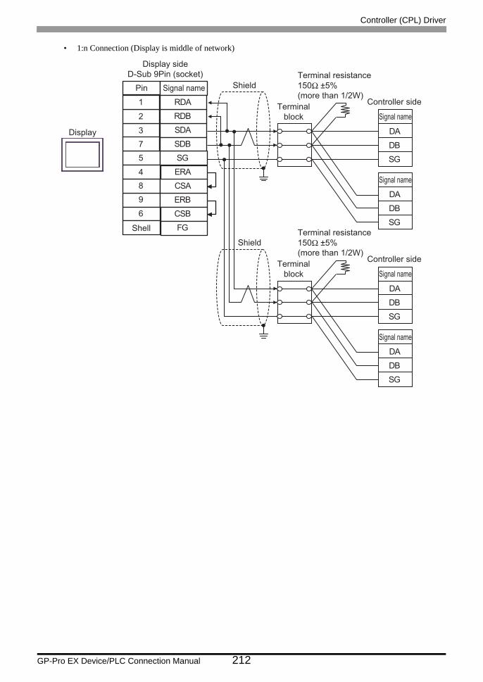
Controller (CPL) Driver
GP-Pro EX Device/PLC Connection Manual 212
• 1:n Connection (Display is middle of network)
DBSG
DA
DBSG
DA
DBSG
DA
DBSG
DA
Signal name
SDA3
RDB2
SG5
4 ERA
SDB
ERB
7
9
CSB6
FG
RDA1
CSA8
Display sideD-Sub 9Pin (socket)
Pin
Shell
Display
Signal name
Signal name
Controller side
Terminal resistance150Ω ±5%(more than 1/2W)
Shield
Terminalblock
Signal name
Signal name
Controller side
Terminal resistance150Ω ±5%(more than 1/2W)
Shield
Terminalblock

Controller (CPL) Driver
GP-Pro EX Device/PLC Connection Manual 213
11C)
• 1:1 Connection
• 1:n Connection (Display is end of network)
DBSG
DA
Signal name
RDB
SDBSG
TERM
CA4-ADPONL-01
CA3-ADPTRM-01
Display
Display side
RDA
SDA
Terminalresistance150Ω ±5%(more than 1/2W)
User-created cable
Shield
Terminalblock Signal name
Controller side
Terminal resistance150Ω ±5%(more than 1/2W)
DBSG
DA
DBSG
DA
Signal name
RDB
SDBSG
TERM
CA4-ADPONL-01
CA3-ADPTRM-01
Display
Display side
RDA
SDA
Terminalresistance150Ω ±5%(more than 1/2W)
User-created cable
Shield
Terminalblock Signal name
Signal name
Controller side
Terminal resistance150Ω ±5%(more than 1/2W)
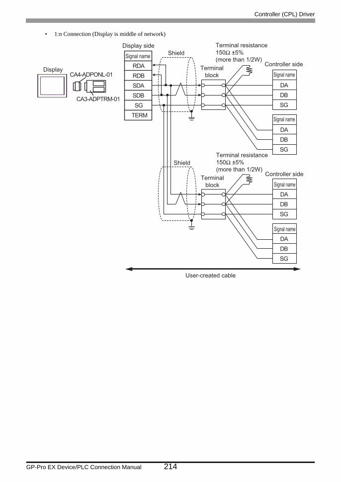
Controller (CPL) Driver
GP-Pro EX Device/PLC Connection Manual 214
• 1:n Connection (Display is middle of network)
DBSG
DA
DBSG
DA
DBSG
DA
DBSG
DA
Signal name
RDB
SDBSG
TERM
CA4-ADPONL-01
CA3-ADPTRM-01
Display
Display side
RDA
SDA
User-created cable
Shield
Terminalblock Signal name
Signal name
Controller side
Terminal resistance150Ω ±5%(more than 1/2W)
Shield
Terminalblock Signal name
Signal name
Controller side
Terminal resistance150Ω ±5%(more than 1/2W)
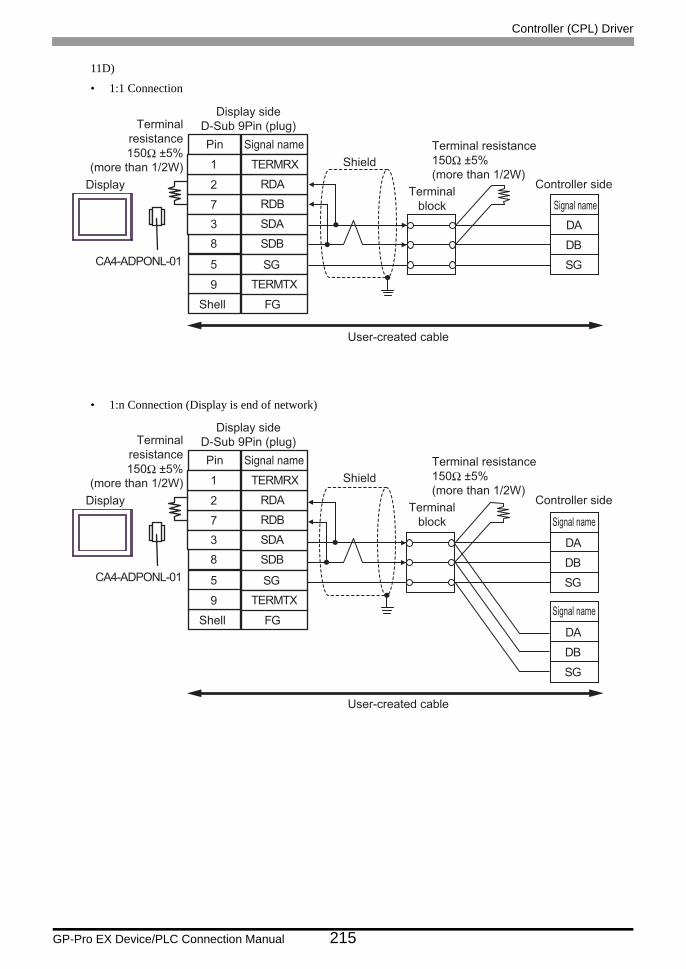
Controller (CPL) Driver
GP-Pro EX Device/PLC Connection Manual 215
11D)
• 1:1 Connection
• 1:n Connection (Display is end of network)
DBSG
DA
CA4-ADPONL-01
Display
Signal name
RDB7
RDA2
SDB8
9 TERMTX
SDA
FG
3
TERMRX1
SG5
Display sideD-Sub 9Pin (plug)Pin
Shell
Terminalresistance150Ω ±5%
(more than 1/2W)
User-created cable
Shield
Terminalblock Signal name
Controller side
Terminal resistance150Ω ±5%(more than 1/2W)
DBSG
DA
DBSG
DA
CA4-ADPONL-01
Display
Signal name
RDB7
RDA2
SDB8
9 TERMTX
SDA
FG
3
TERMRX1
SG5
Display sideD-Sub 9Pin (plug)Pin
Shell
Terminalresistance150Ω ±5%
(more than 1/2W)
User-created cable
Shield
Terminalblock Signal name
Signal name
Controller side
Terminal resistance150Ω ±5%(more than 1/2W)

Controller (CPL) Driver
GP-Pro EX Device/PLC Connection Manual 216
• 1:n Connection (Display is middle of network)
DBSG
DA
DBSG
DA
DBSG
DA
DBSG
DA
CA4-ADPONL-01
Display
Signal name
RDB7
RDA2
SDB8
9 TERMTX
SDA
FG
3
TERMRX1
SG5
Display sideD-Sub 9Pin (plug)Pin
Shell
User-created cable
Shield
Terminalblock Signal name
Signal name
Controller side
Terminal resistance150Ω ±5%(more than 1/2W)
Shield
Terminalblock Signal name
Signal name
Controller side
Terminal resistance150Ω ±5%(more than 1/2W)

Controller (CPL) Driver
GP-Pro EX Device/PLC Connection Manual 217
11E)
• 1:1 Connection
• 1:n Connection (Display is end of network)
RDB
SDBSG
TERM
CA3-ADPCOM-01
CA3-ADPTRM-01
RDA
SDADBSG
DADisplay
Signal nameDisplay side
Terminalresistance150Ω ±5%
(more than 1/2W)
User-created cable
Shield Terminalblock Signal name
Controller side
Terminal resistance150Ω ±5%(more than 1/2W)
DBSG
DA
DBSG
DA
RDB
SDBSG
TERM
CA3-ADPCOM-01
CA3-ADPTRM-01
RDA
SDA
Display
Signal nameDisplay side
Terminalresistance150Ω ±5%
(more than 1/2W)
User-created cable
Shield Terminalblock Signal name
Signal name
Controller side
Terminal resistance150Ω ±5%(more than 1/2W)

Controller (CPL) Driver
GP-Pro EX Device/PLC Connection Manual 218
• 1:n Connection (Display is middle of network)
DBSG
DA
DBSG
DA
DBSG
DA
DBSG
DA
RDB
SDBSG
TERM
CA3-ADPCOM-01
CA3-ADPTRM-01
RDA
SDA
Display
Signal nameDisplay side
User-created cable
Shield Terminalblock Signal name
Signal name
Controller side
Terminal resistance150Ω ±5%(more than 1/2W)
Shield Terminalblock Signal name
Signal name
Controller side
Terminal resistance150Ω ±5%(more than 1/2W)

Controller (CPL) Driver
GP-Pro EX Device/PLC Connection Manual 219
11F)
• 1:1 Connection
• 1:n Connection (Display is end of network)
DBSG
DA
NC3
DATA-2
GND(SG)5NC7
ERA4CSA8
FG
DATA+1
Display sideD-Sub 9Pin (socket)
Display
Terminalresistance150Ω ±5%
(more than 1/2W)
Shell
Pin Signal name
ERB9CSB6
Shield Terminalblock Signal name
Controller side
Terminal resistance150Ω ±5%(more than 1/2W)
DBSG
DA
DBSG
DA
NC3
DATA-2
GND(SG)5NC7
ERA4CSA8
FG
DATA+1
Display sideD-Sub 9Pin (socket)
Display
Terminalresistance150Ω ±5%
(more than 1/2W)
Shell
Pin Signal name
ERB9CSB6
Shield Terminalblock Signal name
Signal name
Controller side
Terminal resistance150Ω ±5%(more than 1/2W)

Controller (CPL) Driver
GP-Pro EX Device/PLC Connection Manual 220
• 1:n Connection (Display is middle of network)
DBSG
DA
DBSG
DA
DBSG
DA
DBSG
DA
NC3
DATA-2
GND(SG)5NC7
ERA4CSA8
FG
DATA+1
Display sideD-Sub 9Pin (socket)
Display
Shell
Pin Signal name
ERB9CSB6
Shield Terminalblock Signal name
Signal name
Controller side
Terminal resistance150Ω ±5%(more than 1/2W)
Shield Terminalblock Signal name
Signal name
Controller side
Terminal resistance150Ω ±5%(more than 1/2W)

Controller (CPL) Driver
GP-Pro EX Device/PLC Connection Manual 221
11G)
• 1:1 Connection
• 1:n Connection (Display is end of network)
*1 The resistance in the Display is used as the termination resistance. Set the value of the DIP Switch on the rear of the Display as shown in the table below.
DIP Switch No. Set Value
1 OFF
2 OFF
3 ON
4 ON
DBSG
DA
Terminalresistance*1
Display
Display sideTerminal block
Signal name
SDARDB
SGERA
SDB
ERBCSB
RDA
CSA
Shield
Terminalblock Signal name
Controller side
Terminal resistance150Ω ±5%(more than 1/2W)
DBSG
DA
DBSG
DA
Terminalresistance*1
Display
Display sideTerminal block
Signal name
SDARDB
SGERA
SDB
ERBCSB
RDA
CSA
Shield
Terminalblock Signal name
Signal name
Controller side
Terminal resistance150Ω ±5%(more than 1/2W)

Controller (CPL) Driver
GP-Pro EX Device/PLC Connection Manual 222
• 1:n Connection (Display is middle of network)
• Set the DIP Switch 1-4 on the rear of the Display to OFF.
DBSG
DA
DBSG
DA
DBSG
DA
DBSG
DA
Display
Display sideTerminal block
Signal name
SDARDB
SGERA
SDB
ERBCSB
RDA
CSA
Shield
Terminalblock Signal name
Signal name
Controller side
Controller side
Terminal resistance150Ω ±5%(more than 1/2W)
Shield
Terminalblock Signal name
Signal name
Terminal resistance150Ω ±5%(more than 1/2W)

Controller (CPL) Driver
GP-Pro EX Device/PLC Connection Manual 223
11H)
• 1:1 Connection
• 1:n Connection (Display is end of network)
DBSG
DA
Display
Terminal resistance150Ω ±5%
(more than 1/2W)Pin
Shell
381
2
46
79
Signal name
LINE(+)
NCNC
GND(SG)RS(RTS)
5VNC
NC
LINE(-)
FG
Display sideD-Sub 9Pin (plug)
5
Shield Terminalblock Signal name
Controller side
Terminal resistance150Ω ±5%(more than 1/2W)
DBSG
DA
DBSG
DA
Display
Terminal resistance150Ω ±5%
(more than 1/2W)Pin
Shell
381
2
46
79
Signal name
LINE(+)
NCNC
GND(SG)RS(RTS)
5VNC
NC
LINE(-)
FG
Display sideD-Sub 9Pin (plug)
5
Shield Terminalblock Signal name
Signal name
Controller side
Terminal resistance150Ω ±5%(more than 1/2W)

Controller (CPL) Driver
GP-Pro EX Device/PLC Connection Manual 224
• 1:n Connection (Display is middle of network)
• The 5V output (Pin #6) on the Display is the power for the Siemens AG’s PROFIBUS connector. Do not use it for other devices.
• In COM on the GP-4107, the SG and FG terminals are isolated.
DBSG
DA
DBSG
DA
DBSG
DA
DBSG
DA
Display
Pin
Shell
381
2
46
79
Signal name
LINE(+)
NCNC
GND(SG)RS(RTS)
5VNC
NC
LINE(-)
FG
Display sideD-Sub 9Pin (plug)
5
ShieldTerminal
block Signal name
Signal name
Controller side
Terminal resistance150Ω ±5%(more than 1/2W)
ShieldTerminal
block Signal name
Signal name
Controller side
Terminal resistance150Ω ±5%(more than 1/2W)

Controller (CPL) Driver
GP-Pro EX Device/PLC Connection Manual 225
11I)
• 1:1 Connection
• 1:n Connection (Display is end of network)
DBSG
DA
Signal name
RDB
SDBSG
TERM
PFXZCBADTM1
Display
Display side
RDA
SDA
Terminal resistance150Ω ±5%
(more than 1/2W)
User-created cable
Shield
Terminalblock Signal name
Controller side
Terminal resistance150Ω ±5%(more than 1/2W)
DBSG
DA
DBSG
DA
Signal name
RDB
SDBSG
TERM
PFXZCBADTM1
Display
Display side
RDA
SDA
Terminal resistance150Ω ±5%
(more than 1/2W)
User-created cable
Shield
Terminalblock Signal name
Signal name
Controller side
Terminal resistance150Ω ±5%(more than 1/2W)

Controller (CPL) Driver
GP-Pro EX Device/PLC Connection Manual 226
• 1:n Connection (Display is middle of network)
DBSG
DA
DBSG
DA
DBSG
DA
DBSG
DA
Signal name
RDB
SDBSG
TERM
PFXZCBADTM1
Display
Display side
RDA
SDA
User-created cable
Shield
Terminalblock Signal name
Signal name
Controller side
Terminal resistance150Ω ±5%(more than 1/2W)
Shield
Terminalblock Signal name
Signal name
Controller side
Terminal resistance150Ω ±5%(more than 1/2W)

Controller (CPL) Driver
GP-Pro EX Device/PLC Connection Manual 227
11J)
• 1:1 Connection
• 1:n Connection (Display is end of network)
DBSG
DA
Terminalblock Signal name
Controller side
Terminal resistance150Ω ±5%(more than 1/2W)
Display
GNDD0D1
(1)
User-created Cable
DBSG
DA
DBSG
DA
Terminalblock Signal name
Signal name
Controller side
Terminal resistance220Ω (1/4W)
Display
GNDD0D1
(1)
User-created Cable

Controller (CPL) Driver
GP-Pro EX Device/PLC Connection Manual 228
• 1:n Connection (Display is middle of network)
Number Name Notes
(1)RJ45 RS-485 Cable (5m) by Pro-face
PFXZLMCBRJR81
DBSG
DA
DBSG
DA
DBSG
DA
DBSG
DA
Terminalblock Signal name
Signal name
Controller side
Terminal resistance220Ω (1/4W)
Terminalblock Signal name
Signal name
Controller side
Terminal resistance220Ω (1/4W)
Display
GNDD0D1
(1)
User-created Cable

Controller (CPL) Driver
GP-Pro EX Device/PLC Connection Manual 229
6 Supported Devices
The following table shows the range of supported device addresses. Note that the actually supported range varies
depending on the External Device to be used. Please check the actual range in your External Device manual.
Enter the External Device address in the dialog box below.
6.1 SDC10
: This address can be specified as system data area.
1. Address Enter the address.2. Browse A list of available parameters is displayed.
Click the parameter you want to use, and press "Select" to enter the address.
Device Bit Address Word Address 32 bits Remarks
Data 00501.0-04504.F 00501-04504 *1
*1 When bits are written, the Display reads the corresponding word address from the External Device, setsparticular bits of that word address to ON, and then returns the resulting address to the External Device. Notethat the correct data may not be written if you change the word address using the ladder program while theDisplay reads data from the External Device and returns it.
• Setting [Enable System Data Area] in the system area setting of GP-Pro EX may cause malfunction. Do not set [Enable System Data Area].
• You can set only the reading area size in the Controller's system area setting. Refer to the GP-Pro EX Reference Manual for the reading area size.
Cf. GP-Pro EX Reference Manual "LS Area (only for direct access method Area)"
• Refer to the precautions on manual notation for icons in the table.
"Manual Symbols and Terminology"
• Even if you use a nonexistent address, the read error may not be displayed. In this case, "0" is retained for the read data. Note that the write error is displayed.
1
2

Controller (CPL) Driver
GP-Pro EX Device/PLC Connection Manual 230
6.2 SDC15/SDC25/SDC26/SDC35/SDC36
: This address can be specified as system data area.
Device Bit Address Word Address 32 bits Remarks
Data 00273.0-31243.F 00273-31243 *1
*1 When bits are written, the Display reads the corresponding word address from the External Device, setsparticular bits of that word address to ON, and then returns the resulting address to the External Device. Notethat the correct data may not be written if you change the word address using the ladder program while theDisplay reads data from the External Device and returns it.
• Setting [Enable System Data Area] in the system area setting of GP-Pro EX may cause malfunction. Do not set [Enable System Data Area].
• You can set only the reading area size in the Controller's system area setting. Refer to the GP-Pro EX Reference Manual for the reading area size.
Cf. GP-Pro EX Reference Manual "LS Area (only for direct access method Area)"
• Refer to the precautions on manual notation for icons in the table.
"Manual Symbols and Terminology"
• Even if you use a nonexistent address, the read error may not be displayed. In this case, "0" is retained for the read data. Note that the write error is displayed.

Controller (CPL) Driver
GP-Pro EX Device/PLC Connection Manual 231
6.3 SDC20/SDC21
: This address can be specified as system data area.
Device Bit Address Word Address 32 bits Remarks
Data 0301.0-0690.F 0301-0690 *1
*1 When bits are written, the Display reads the corresponding word address from the External Device, setsparticular bits of that word address to ON, and then returns the resulting address to the External Device. Notethat the correct data may not be written if you change the word address using the ladder program while theDisplay reads data from the External Device and returns it.
• Setting [Enable System Data Area] in the system area setting of GP-Pro EX may cause malfunction. Do not set [Enable System Data Area].
• You can set only the reading area size in the Controller's system area setting. Refer to the GP-Pro EX Reference Manual for the reading area size.
Cf. GP-Pro EX Reference Manual "LS Area (only for direct access method Area)"
• Refer to the precautions on manual notation for icons in the table.
"Manual Symbols and Terminology"
• Even if you use a nonexistent address, the read error may not be displayed. In this case, "0" is retained for the read data. Note that the write error is displayed.

Controller (CPL) Driver
GP-Pro EX Device/PLC Connection Manual 232
6.4 SDC30/SDC31
: This address can be specified as system data area.
Device Bit Address Word Address 32 bits Remarks
Data 00501.0-06049.F 00501-06049 *1
*1 When bits are written, the Display reads the corresponding word address from the External Device, setsparticular bits of that word address to ON, and then returns the resulting address to the External Device. Notethat the correct data may not be written if you change the word address using the ladder program while theDisplay reads data from the External Device and returns it.
• Setting [Enable System Data Area] in the system area setting of GP-Pro EX may cause malfunction. Do not set [Enable System Data Area].
• You can set only the reading area size in the Controller's system area setting. Refer to the GP-Pro EX Reference Manual for the reading area size.
Cf. GP-Pro EX Reference Manual "LS Area (only for direct access method Area)"
• Refer to the precautions on manual notation for icons in the table.
"Manual Symbols and Terminology"
• Even if you use a nonexistent address, the read error may not be displayed. In this case, "0" is retained for the read data. Note that the write error is displayed.

Controller (CPL) Driver
GP-Pro EX Device/PLC Connection Manual 233
6.5 SDC40A
: This address can be specified as system data area.
Device Bit Address Word Address 32 bits Remarks
Data 00501.0-06100.F 00501-06100 *1
*1 When bits are written, the Display reads the corresponding word address from the External Device, setsparticular bits of that word address to ON, and then returns the resulting address to the External Device. Notethat the correct data may not be written if you change the word address using the ladder program while theDisplay reads data from the External Device and returns it.
• Setting [Enable System Data Area] in the system area setting of GP-Pro EX may cause malfunction. Do not set [Enable System Data Area].
• You can set only the reading area size in the Controller's system area setting. Refer to the GP-Pro EX Reference Manual for the reading area size.
Cf. GP-Pro EX Reference Manual "LS Area (only for direct access method Area)"
• Refer to the precautions on manual notation for icons in the table.
"Manual Symbols and Terminology"
• Even if you use a nonexistent address, the read error may not be displayed. In this case, "0" is retained for the read data. Note that the write error is displayed.

Controller (CPL) Driver
GP-Pro EX Device/PLC Connection Manual 234
6.6 SDC40B
: This address can be specified as system data area.
Device Bit Address Word Address 32 bits Remarks
Data 00501.0-08902.F 00501-08902 *1
*1 When bits are written, the Display reads the corresponding word address from the External Device, setsparticular bits of that word address to ON, and then returns the resulting address to the External Device. Notethat the correct data may not be written if you change the word address using the ladder program while theDisplay reads data from the External Device and returns it.
• Setting [Enable System Data Area] in the system area setting of GP-Pro EX may cause malfunction. Do not set [Enable System Data Area].
• You can set only the reading area size in the Controller's system area setting. Refer to the GP-Pro EX Reference Manual for the reading area size.
Cf. GP-Pro EX Reference Manual "LS Area (only for direct access method Area)"
• Refer to the precautions on manual notation for icons in the table.
"Manual Symbols and Terminology"
• Even if you use a nonexistent address, the read error may not be displayed. In this case, "0" is retained for the read data. Note that the write error is displayed.

Controller (CPL) Driver
GP-Pro EX Device/PLC Connection Manual 235
6.7 SDC40G
: This address can be specified as system data area.
Device Bit Address Word Address 32 bits Remarks
Data 00501.0-06100.F 00501-06100 *1
*1 When bits are written, the Display reads the corresponding word address from the External Device, setsparticular bits of that word address to ON, and then returns the resulting address to the External Device. Notethat the correct data may not be written if you change the word address using the ladder program while theDisplay reads data from the External Device and returns it.
• Setting [Enable System Data Area] in the system area setting of GP-Pro EX may cause malfunction. Do not set [Enable System Data Area].
• You can set only the reading area size in the Controller's system area setting. Refer to the GP-Pro EX Reference Manual for the reading area size.
Cf. GP-Pro EX Reference Manual "LS Area (only for direct access method Area)"
• Refer to the precautions on manual notation for icons in the table.
"Manual Symbols and Terminology"
• Even if you use a nonexistent address, the read error may not be displayed. In this case, "0" is retained for the read data. Note that the write error is displayed.

Controller (CPL) Driver
GP-Pro EX Device/PLC Connection Manual 236
6.8 SDC45/46
: This address can be specified as system data area.
Device Bit Address Word Address 32 bits Remarks
Data 1000.0-BFFF.F 1000-BFFF *1
*1 When bits are written, the Display reads the corresponding word address from the External Device, setsparticular bits of that word address to ON, and then returns the resulting address to the External Device. Notethat the correct data may not be written if you change the word address using the ladder program while theDisplay reads data from the External Device and returns it.
• Setting [Enable System Data Area] in the system area setting of GP-Pro EX may cause malfunction. Do not set [Enable System Data Area].
• You can set only the reading area size in the Controller's system area setting. Refer to the GP-Pro EX Reference Manual for the reading area size.
Cf. GP-Pro EX Reference Manual "LS Area (only for direct access method Area)"
• Refer to the precautions on manual notation for icons in the table.
"Manual Symbols and Terminology"
• Even if you use a nonexistent address, the read error may not be displayed. In this case, "0" is retained for the read data. Note that the write error is displayed.

Controller (CPL) Driver
GP-Pro EX Device/PLC Connection Manual 237
6.9 DMC10
: This address can be specified as system data area.
Device Bit Address Word Address 32 bits Remarks
Data 01001.0-07806.F 01001-07806 *1
*1 When bits are written, the Display reads the corresponding word address from the External Device, setsparticular bits of that word address to ON, and then returns the resulting address to the External Device. Notethat the correct data may not be written if you change the word address using the ladder program while theDisplay reads data from the External Device and returns it.
• Setting [Enable System Data Area] in the system area setting of GP-Pro EX may cause malfunction. Do not set [Enable System Data Area].
• You can set only the reading area size in the Controller's system area setting. Refer to the GP-Pro EX Reference Manual for the reading area size.
Cf. GP-Pro EX Reference Manual "LS Area (only for direct access method Area)"
• Refer to the precautions on manual notation for icons in the table.
"Manual Symbols and Terminology"
• Even if you use a nonexistent address, the read error may not be displayed. In this case, "0" is retained for the read data. Note that the write error is displayed.

Controller (CPL) Driver
GP-Pro EX Device/PLC Connection Manual 238
6.10 DMC50
: This address can be specified as system data area.
Device Bit Address Word Address 64 bits Remarks
Data 00000001.00-CF1FFF3A.1F 00000001-CF1FFF3A
*1
*1 When bits are written, the Display reads the corresponding word address from the External Device, setsparticular bits of that word address to ON, and then returns the resulting address to the External Device. Notethat the correct data may not be written if you change the word address using the ladder program while theDisplay reads data from the External Device and returns it.
• Setting [Enable System Data Area] in the system area setting of GP-Pro EX may cause malfunction. Do not set [Enable System Data Area].
• You can set only the reading area size in the Controller's system area setting. Refer to the GP-Pro EX Reference Manual for the reading area size.
Cf. GP-Pro EX Reference Manual "LS Area (only for direct access method Area)"
• Refer to the precautions on manual notation for icons in the table.
"Manual Symbols and Terminology"
• Even if you use a nonexistent address, the read error may not be displayed. In this case, "0" is retained for the read data. Note that the write error is displayed.

Controller (CPL) Driver
GP-Pro EX Device/PLC Connection Manual 239
6.11 DCP31/DCP32
: This address can be specified as system data area.
Device Bit Address Word Address 32 bits Remarks
Data 00501.0-04600.F 00501-04600 *1
*1 When bits are written, the Display reads the corresponding word address from the External Device, setsparticular bits of that word address to ON, and then returns the resulting address to the External Device. Notethat the correct data may not be written if you change the word address using the ladder program while theDisplay reads data from the External Device and returns it.
• Setting [Enable System Data Area] in the system area setting of GP-Pro EX may cause malfunction. Do not set [Enable System Data Area].
• You can set only the reading area size in the Controller's system area setting. Refer to the GP-Pro EX Reference Manual for the reading area size.
Cf. GP-Pro EX Reference Manual "LS Area (only for direct access method Area)"
• Refer to the precautions on manual notation for icons in the table.
"Manual Symbols and Terminology"
• Even if you use a nonexistent address, the read error may not be displayed. In this case, "0" is retained for the read data. Note that the write error is displayed.

Controller (CPL) Driver
GP-Pro EX Device/PLC Connection Manual 240
6.12 DCP551
: This address can be specified as system data area.
Device Bit Address Word Address 32 bits Remarks
Data 00256.0-01712.F 00256-01712 *1
*1 When bits are written, the Display reads the corresponding word address from the External Device, setsparticular bits of that word address to ON, and then returns the resulting address to the External Device. Notethat the correct data may not be written if you change the word address using the ladder program while theDisplay reads data from the External Device and returns it.
• Setting [Enable System Data Area] in the system area setting of GP-Pro EX may cause malfunction. Do not set [Enable System Data Area].
• You can set only the reading area size in the Controller's system area setting. Refer to the GP-Pro EX Reference Manual for the reading area size.
Cf. GP-Pro EX Reference Manual "LS Area (only for direct access method Area)"
• Refer to the precautions on manual notation for icons in the table.
"Manual Symbols and Terminology"
• Even if you use a nonexistent address, the read error may not be displayed. In this case, "0" is retained for the read data. Note that the write error is displayed.

Controller (CPL) Driver
GP-Pro EX Device/PLC Connection Manual 241
6.13 DCP552
: This address can be specified as system data area.
Device Bit Address Word Address 32 bits Remarks
Data 00256.0-02003.F 00256-02003 *1
*1 When bits are written, the Display reads the corresponding word address from the External Device, setsparticular bits of that word address to ON, and then returns the resulting address to the External Device. Notethat the correct data may not be written if you change the word address using the ladder program while theDisplay reads data from the External Device and returns it.
• Setting [Enable System Data Area] in the system area setting of GP-Pro EX may cause malfunction. Do not set [Enable System Data Area].
• You can set only the reading area size in the Controller's system area setting. Refer to the GP-Pro EX Reference Manual for the reading area size.
Cf. GP-Pro EX Reference Manual "LS Area (only for direct access method Area)"
• Refer to the precautions on manual notation for icons in the table.
"Manual Symbols and Terminology"
• Even if you use a nonexistent address, the read error may not be displayed. In this case, "0" is retained for the read data. Note that the write error is displayed.

Controller (CPL) Driver
GP-Pro EX Device/PLC Connection Manual 242
6.14 CMC10B
: This address can be specified as system data area.
Device Bit Address Word Address 32 bits Remarks
Data 00401.0-07868.F 00401-07868 *1
*1 When bits are written, the Display reads the corresponding word address from the External Device, setsparticular bits of that word address to ON, and then returns the resulting address to the External Device. Notethat the correct data may not be written if you change the word address using the ladder program while theDisplay reads data from the External Device and returns it.
• Setting [Enable System Data Area] in the system area setting of GP-Pro EX may cause malfunction. Do not set [Enable System Data Area].
• You can set only the reading area size in the Controller's system area setting. Refer to the GP-Pro EX Reference Manual for the reading area size.
Cf. GP-Pro EX Reference Manual "LS Area (only for direct access method Area)"
• Refer to the precautions on manual notation for icons in the table.
"Manual Symbols and Terminology"
• Even if you use a nonexistent address, the read error may not be displayed. In this case, "0" is retained for the read data. Note that the write error is displayed.

Controller (CPL) Driver
GP-Pro EX Device/PLC Connection Manual 243
6.15 PBC
: This address can be specified as system data area.
Device Bit Address Word Address 32 bits Remarks
Data 1000.0-3029.F 1000-3029 *1
*1 When bits are written, the Display reads the corresponding word address from the External Device, setsparticular bits of that word address to ON, and then returns the resulting address to the External Device. Notethat the correct data may not be written if you change the word address using the ladder program while theDisplay reads data from the External Device and returns it.
• Setting [Enable System Data Area] in the system area setting of GP-Pro EX may cause malfunction. Do not set [Enable System Data Area].
• You can set only the reading area size in the Controller's system area setting. Refer to the GP-Pro EX Reference Manual for the reading area size.
Cf. GP-Pro EX Reference Manual "LS Area (only for direct access method Area)"
• Refer to the precautions on manual notation for icons in the table.
"Manual Symbols and Terminology"

Controller (CPL) Driver
GP-Pro EX Device/PLC Connection Manual 244
6.16 CMS/CMF015
: This address can be specified as system data area.
Device Bit Address Word Address 32 bits Remarks
Data 1001.0-5214.F 1001-5214 *1
*1 When bits are written, the Display reads the corresponding word address from the External Device, setsparticular bits of that word address to ON, and then returns the resulting address to the External Device. Notethat the correct data may not be written if you change the word address using the ladder program while theDisplay reads data from the External Device and returns it.
• Setting [Enable System Data Area] in the system area setting of GP-Pro EX may cause malfunction. Do not set [Enable System Data Area].
• You can set only the reading area size in the Controller's system area setting. Refer to the GP-Pro EX Reference Manual for the reading area size.
Cf. GP-Pro EX Reference Manual "LS Area (only for direct access method Area)"
• Refer to the precautions on manual notation for icons in the table.
"Manual Symbols and Terminology"

Controller (CPL) Driver
GP-Pro EX Device/PLC Connection Manual 245
6.17 CMQ-V
: This address can be specified as system data area.
Device Bit Address Word Address 32 bits Remarks
Data 1001.0-5222.F 1001-5222 *1
*1 When bits are written, the Display reads the corresponding word address from the External Device, setsparticular bits of that word address to ON, and then returns the resulting address to the External Device. Notethat the correct data may not be written if you change the word address using the ladder program while theDisplay reads data from the External Device and returns it.
• Setting [Enable System Data Area] in the system area setting of GP-Pro EX may cause malfunction. Do not set [Enable System Data Area].
• You can set only the reading area size in the Controller's system area setting. Refer to the GP-Pro EX Reference Manual for the reading area size.
Cf. GP-Pro EX Reference Manual "LS Area (only for direct access method Area)"
• Refer to the precautions on manual notation for icons in the table.
"Manual Symbols and Terminology"

Controller (CPL) Driver
GP-Pro EX Device/PLC Connection Manual 246
6.18 MPC
: This address can be specified as system data area.
Device Bit Address Word Address 32 bits Remarks
Data 1001.0-5220.F 1001-5220 *1
*1 When bits are written, the Display reads the corresponding word address from the External Device, setsparticular bits of that word address to ON, and then returns the resulting address to the External Device. Notethat the correct data may not be written if you change the word address using the ladder program while theDisplay reads data from the External Device and returns it.
• Setting [Enable System Data Area] in the system area setting of GP-Pro EX may cause malfunction. Do not set [Enable System Data Area].
• You can set only the reading area size in the Controller's system area setting. Refer to the GP-Pro EX Reference Manual for the reading area size.
Cf. GP-Pro EX Reference Manual "LS Area (only for direct access method Area)"
• Refer to the precautions on manual notation for icons in the table.
"Manual Symbols and Terminology"

Controller (CPL) Driver
GP-Pro EX Device/PLC Connection Manual 247
6.19 MVF
: This address can be specified as system data area.
Device Bit Address Word Address 32 bits Remarks
Data 1001.0-5217.F 1001-5217 *1
*1 When bits are written, the Display reads the corresponding word address from the External Device, setsparticular bits of that word address to ON, and then returns the resulting address to the External Device. Notethat the correct data may not be written if you change the word address using the ladder program while theDisplay reads data from the External Device and returns it.
• Setting [Enable System Data Area] in the system area setting of GP-Pro EX may cause malfunction. Do not set [Enable System Data Area].
• You can set only the reading area size in the Controller's system area setting. Refer to the GP-Pro EX Reference Manual for the reading area size.
Cf. GP-Pro EX Reference Manual "LS Area (only for direct access method Area)"
• Refer to the precautions on manual notation for icons in the table.
"Manual Symbols and Terminology"

Controller (CPL) Driver
GP-Pro EX Device/PLC Connection Manual 248
6.20 CML/CMF050
: This address can be specified as system data area.
Device Bit Address Word Address 32 bits Remarks
Data 1201.0-5399.F 1201-5399 *1
*1 When bits are written, the Display reads the corresponding word address from the External Device, setsparticular bits of that word address to ON, and then returns the resulting address to the External Device. Notethat the correct data may not be written if you change the word address using the ladder program while theDisplay reads data from the External Device and returns it.
• Setting [Enable System Data Area] in the system area setting of GP-Pro EX may cause malfunction. Do not set [Enable System Data Area].
• You can set only the reading area size in the Controller's system area setting. Refer to the GP-Pro EX Reference Manual for the reading area size.
Cf. GP-Pro EX Reference Manual "LS Area (only for direct access method Area)"
• Refer to the precautions on manual notation for icons in the table.
"Manual Symbols and Terminology"
• When an address that does not exist in the controller is read out, the value of 65535 is read out but no error is displayed. Also, when an address that does not exist in the controller is used in the project, the value of 65535 may be read out even when it is the address data existing in the controller.

Controller (CPL) Driver
GP-Pro EX Device/PLC Connection Manual 249
6.21 AUR350C
: This address can be specified as system data area.
Device Bit Address Word Address 32 bits Remarks
Data 1000.0-4159.F 1000-4159 *1
*1 When bits are written, the Display reads the corresponding word address from the External Device, setsparticular bits of that word address to ON, and then returns the resulting address to the External Device. Notethat the correct data may not be written if you change the word address using the ladder program while theDisplay reads data from the External Device and returns it.
• Setting [Enable System Data Area] in the system area setting of GP-Pro EX may cause malfunction. Do not set [Enable System Data Area].
• Change the setting for [Text Data Mode] to "2" in the communication settings of GP-Pro EX. The correct value is not displayed when the initial value "1" is specified.
• You can set only the reading area size in the Controller's system area setting. Refer to the GP-Pro EX Reference Manual for the reading area size.
Cf. GP-Pro EX Reference Manual "LS Area (only for direct access method Area)"
• Refer to the precautions on manual notation for icons in the table.
"Manual Symbols and Terminology"

Controller (CPL) Driver
GP-Pro EX Device/PLC Connection Manual 250
6.22 AUR450C
: This address can be specified as system data area.
Device Bit Address Word Address 32 bits Remarks
Data 1000.0-8159.F 1000-8159 *1
*1 When bits are written, the Display reads the corresponding word address from the External Device, setsparticular bits of that word address to ON, and then returns the resulting address to the External Device. Notethat the correct data may not be written if you change the word address using the ladder program while theDisplay reads data from the External Device and returns it.
• Setting [Enable System Data Area] in the system area setting of GP-Pro EX may cause malfunction. Do not set [Enable System Data Area].
• Change the setting for [Text Data Mode] to "2" in the communication settings of GP-Pro EX. The correct value is not displayed when the initial value "1" is specified.
• You can set only the reading area size in the Controller's system area setting. Refer to the GP-Pro EX Reference Manual for the reading area size.
Cf. GP-Pro EX Reference Manual "LS Area (only for direct access method Area)"
• Refer to the precautions on manual notation for icons in the table.
"Manual Symbols and Terminology"

Controller (CPL) Driver
GP-Pro EX Device/PLC Connection Manual 251
6.23 RX
: This address can be specified as system data area.
Device Bit Address Word Address 32 bits Remarks
Data 1000.0-2472.F 1000-2472 *1
*1 When bits are written, the Display reads the corresponding word address from the External Device, setsparticular bits of that word address to ON, and then returns the resulting address to the External Device. Notethat the correct data may not be written if you change the word address using the ladder program while theDisplay reads data from the External Device and returns it.
• Setting [Enable System Data Area] in the system area setting of GP-Pro EX may cause malfunction. Do not set [Enable System Data Area].
• You can set only the reading area size in the Controller's system area setting. Refer to the GP-Pro EX Reference Manual for the reading area size.
Cf. GP-Pro EX Reference Manual "LS Area (only for direct access method Area)"
• Refer to the precautions on manual notation for icons in the table.
"Manual Symbols and Terminology"

Controller (CPL) Driver
GP-Pro EX Device/PLC Connection Manual 252
7 Device Code and Address Code
Use device code and address code when you select "Device Type & Address" for the address type of the data
display or other devices.
7.1 SDC10
7.2 SDC15 /SDC 25/SDC26 / SDC35/SDC36
7.3 SDC20/SDC21
7.4 SDC30/SDC31
7.5 SDC40A
7.6 SDC40B
Device Device NameDevice Code
(HEX)Address Code
Data --- 0080 Word Address
Device Device NameDevice Code
(HEX)Address Code
Data --- 0080 Word Address
Device Device NameDevice Code
(HEX)Address Code
Data --- 0080 Word Address
Device Device NameDevice Code
(HEX)Address Code
Data --- 0080 Word Address
Device Device NameDevice Code
(HEX)Address Code
Data --- 0080 Word Address
Device Device NameDevice Code
(HEX)Address Code
Data --- 0080 Word Address

Controller (CPL) Driver
GP-Pro EX Device/PLC Connection Manual 253
7.7 SDC40G
7.8 SDC45/46
7.9 DMC10
7.10 DMC50
Device Device NameDevice Code
(HEX)Address Code
Data --- 0080 Word Address
Device Device NameDevice Code
(HEX)Address Code
Data --- 0080 Word Address
Device Device NameDevice Code
(HEX)Address Code
Data --- 0080 Word Address
Device Device NameDevice Code
(HEX)Address Code
Data 000 0080 Word Address
Data 001 0081 Word Address
Data 002 0082 Word Address
Data 021 00A1 Word Address
Data 022 00A2 Word Address
Data 023 00A3 Word Address
Data 041 00C1 Word Address
Data 045 00C5 Word Address
Data 061 00E1 Word Address
Data 071 00F1 Word Address
Data 074 00F4 Word Address
Data 0A1 0121 Word Address
Data 0A2 0122 Word Address
Data 0A3 0123 Word Address
Data 0C1 0141 Word Address
Data 0C3 0143 Word Address
Continued to next page.

Controller (CPL) Driver
GP-Pro EX Device/PLC Connection Manual 254
Data 0C4 0144 Word Address
Data 0C5 0145 Word Address
Data 0C6 0146 Word Address
Data 0E1 0161 Word Address
Data 0E2 0162 Word Address
Data 0E3 0163 Word Address
Data 0E5 0165 Word Address
Data 0E6 0166 Word Address
Data 0E7 0167 Word Address
Data 0E8 0168 Word Address
Data 0F1 0171 Word Address
Data 0F2 0172 Word Address
Data 0F3 0173 Word Address
Data 103 0183 Word Address
Data 201 0281 Word Address
Data 202 0282 Word Address
Data 203 0283 Word Address
Data 211 0291 Word Address
Data 212 0292 Word Address
Data 213 0293 Word Address
Data 214 0294 Word Address
Data 234 02B4 Word Address
Data 235 02B5 Word Address
Data 236 02B6 Word Address
Data 241 02C1 Word Address
Data 242 02C2 Word Address
Data 243 02C3 Word Address
Data 301 0381 Word Address
Data
801802.....9FE9FF
08810882.....
0A7E0A7F
Word Address
Continued to next page.
Device Device NameDevice Code
(HEX)Address Code

Controller (CPL) Driver
GP-Pro EX Device/PLC Connection Manual 255
7.11 DCP31/DCP32
7.12 DCP551
7.13 DCP552
7.14 CMC10B
7.15 PBC
7.16 CMS/CMF015
Data C00 0C80 Word Address
Data
C01C02.....C62C63
0C810C82.....
0CE20CE3
Word Address
Data CF1 0D71 Word Address
Device Device NameDevice Code
(HEX)Address Code
Data --- 0080 Word Address
Device Device NameDevice Code
(HEX)Address Code
Data --- 0080 Word Address
Device Device NameDevice Code
(HEX)Address Code
Data --- 0080 Word Address
Device Device NameDevice Code
(HEX)Address Code
Data --- 0080 Word Address
Device Device NameDevice Code
(HEX)Address Code
Data --- 0080 Word Address
Device Device NameDevice Code
(HEX)Address Code
Data --- 0080 Word Address
Device Device NameDevice Code
(HEX)Address Code

Controller (CPL) Driver
GP-Pro EX Device/PLC Connection Manual 256
7.17 CMQ-V
7.18 MPC
7.19 MVF
7.20 CML/CMF050
7.21 AUR350C
7.22 AUR450C
7.23 RX
Device Device NameDevice Code
(HEX)Address Code
Data --- 0080 Word Address
Device Device NameDevice Code
(HEX)Address Code
Data --- 0080 Word Address
Device Device NameDevice Code
(HEX)Address Code
Data --- 0080 Word Address
Device Device NameDevice Code
(HEX)Address Code
Data --- 0080 Word Address
Device Device NameDevice Code
(HEX)Address Code
Data --- 0080 Word Address
Device Device NameDevice Code
(HEX)Address Code
Data --- 0080 Word Address
Device Device NameDevice Code
(HEX)Address Code
Data --- 0080 Word Address

Controller (CPL) Driver
GP-Pro EX Device/PLC Connection Manual 257
8 Error Messages
Error messages are displayed on the Display screen as follows: "No.: Device Name: Error Message (Error
Occurrence Area)". Each description is shown below.
Display Examples of Error Messages
"RHAA035: PLC1: Error has been responded for device write command (Error Code: 2[02H])"
Notes on Using the Device MonitorThe External Device has inaccessible areas.
If you attempt to display a range that includes inaccessible areas using the bit or word batch monitor, an error may
occur and no data may be displayed.
In this case, set the address you want to display as the first one, or use the random monitor.
Item Description
No. Error No.
Device Name Name of the External Device where an error has occurred. Device name is the title of the External Device set with GP-Pro EX. (Initial value [PLC1])
Error Message Displays messages related to an error that has occurred.
Error Occurrence Area
Displays the IP address or device address of the External Device where an error has occurred, or error codes received from the External Device.
• IP address is displayed as "IP address (Decimal): MAC address (Hex)".• Device address is displayed as "Address: Device address".• Received error codes are displayed as "Decimal [Hex]".
• Refer to your External Device manual for details on received error codes.• Refer to "Display-related errors" in "Maintenance/Troubleshooting Guide" for details on the
error messages common to the driver.

Controller (CPL) Driver
GP-Pro EX Device/PLC Connection Manual 258