controller installation manual · controller installation manual variable frequency programmable...
TRANSCRIPT

MOTION CONTROL ENGINEERING, INC.11380 WHITE ROCK ROAD
RANCHO CORDOVA, CA 95742TELEPHONE (916) 463-9200 FAX (916) 463-9201
CONTROLLER INSTALLATION MANUAL
Variable Frequency
Programmable Traction ControllerVFMC-1000-PTC Series M (Open Loop)VFMC-1000-PTC Series M (Flux Vector)
Compliant with ASME A17.1 - 2000 / CSA B44-00 and later codes
Part # 42-02-2P22 Rev. B.9 June 2010
Applicable to EMS, IDM, Yaskawa, MagneTek (G5+ / GPD515+),MagneTek (HPV 900), Yaskawa (F7) and TORQMAX AC Drives
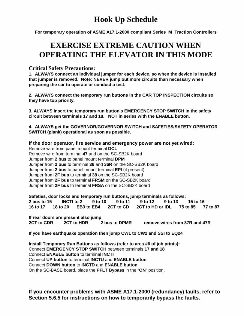
Hook Up Schedule
For temporary operation of ASME A17.1-2000 compliant Series M Traction Controllers
EXERCISE EXTREME CAUTION WHENOPERATING THE ELEVATOR IN THIS MODE
Critical Safety Precautions: 1. ALWAYS connect an individual jumper for each device, so when the device is installedthat jumper is removed. Note: NEVER jump out more circuits than necessary whenpreparing the car to operate or conduct a test.
2. ALWAYS connect the temporary run buttons in the CAR TOP INSPECTION circuits sothey have top priority.
3. ALWAYS insert the temporary run button's EMERGENCY STOP SWITCH in the safetycircuit between terminals 17 and 18. NOT in series with the ENABLE button.
4. ALWAYS get the GOVERNOR/GOVERNOR SWITCH and SAFETIES/SAFETY OPERATORSWITCH (plank) operational as soon as possible.
If the door operator, fire service and emergency power are not yet wired:Remove wire from panel mount terminal DCLRemove wire from terminal 47 and on the SC-SB2K boardJumper from 2 bus to panel mount terminal DPMJumper from 2 bus to terminal 36 and 36R on the SC-SB2K boardJumper from 2 bus to panel mount terminal EPI (if present)Jumper from 2F bus to terminal 38 on the SC-SB2K boardJumper from 2F bus to terminal FRSM on the SC-SB2K boardJumper from 2F bus to terminal FRSA on the SC-SB2K board Safeties, door locks and temporary run buttons, jump terminals as follows:2 bus to 15 INCTI to 2 9 to 10 9 to 11 9 to 12 9 to 13 15 to 1616 to 17 18 to 20 EB3 to EB4 2CT to CD 2CT to HD or IDL 75 to 85 77 to 87
If rear doors are present also jump:2CT to CDR 2CT to HDR 2 bus to DPMR remove wires from 37R and 47R
If you have earthquake operation then jump CW1 to CW2 and SSI to EQ24 Install Temporary Run Buttons as follows (refer to area #6 of job prints):Connect EMERGENCY STOP SWITCH between terminals 17 and 18Connect ENABLE button to terminal INCTIConnect UP button to terminal INCTU and ENABLE buttonConnect DOWN button to INCTD and ENABLE buttonOn the SC-BASE board, place the PFLT Bypass in the “ON” position.
If you encounter problems with ASME A17.1-2000 (redundancy) faults, refer toSection 5.6.5 for instructions on how to temporarily bypass the faults.
42-02-2P22 TABLE OF CONTENTS • i
TABLE OF CONTENTS
IMPORTANT NOTES & PRECAUTIONS . . . . . . . . . . . . . . . . . . . . . . . . . . . . . . . xi
SECTION 1PRODUCT DESCRIPTION
1.0 General Information . . . . . . . . . . . . . . . . . . . . . . . . . . . . . . . . . . . . . . . . . . . . . . . 1-1
1.1 Car Controller Physical Description . . . . . . . . . . . . . . . . . . . . . . . . . . . . . . . . . . . 1-2
1.2 Car Controller Functional Description . . . . . . . . . . . . . . . . . . . . . . . . . . . . . . . . . 1-141.2.1 Car Operation Control (COC) . . . . . . . . . . . . . . . . . . . . . . . . . . . . . . . . . 1-151.2.2 Car Communication Control (CCC) . . . . . . . . . . . . . . . . . . . . . . . . . . . . . 1-151.2.3 Programming and Diagnostics Tools . . . . . . . . . . . . . . . . . . . . . . . . . . . 1-161.2.4 Duplexing . . . . . . . . . . . . . . . . . . . . . . . . . . . . . . . . . . . . . . . . . . . . . . . . 1-161.2.5 Car Motion Control (CMC) . . . . . . . . . . . . . . . . . . . . . . . . . . . . . . . . . . . 1-161.2.6 VVVF Drive . . . . . . . . . . . . . . . . . . . . . . . . . . . . . . . . . . . . . . . . . . . . . . . 1-161.2.7 Typical Sequence of Operation . . . . . . . . . . . . . . . . . . . . . . . . . . . . . . . . 1-16
1.3 Landing Systems . . . . . . . . . . . . . . . . . . . . . . . . . . . . . . . . . . . . . . . . . . . . . . . . 1-171.3.1 LS-QUTE-2K . . . . . . . . . . . . . . . . . . . . . . . . . . . . . . . . . . . . . . . . . . . . . 1-171.3.2 LS-STAN . . . . . . . . . . . . . . . . . . . . . . . . . . . . . . . . . . . . . . . . . . . . . . . . 1-18
SECTION 2INSTALLATION
2.0 General Information . . . . . . . . . . . . . . . . . . . . . . . . . . . . . . . . . . . . . . . . . . . . . . . 2-12.0.1 Site Selection . . . . . . . . . . . . . . . . . . . . . . . . . . . . . . . . . . . . . . . . . . . . . . 2-12.0.2 Environmental Considerations . . . . . . . . . . . . . . . . . . . . . . . . . . . . . . . . . 2-12.0.3 Recommended Tools and Test Equipment . . . . . . . . . . . . . . . . . . . . . . . . 2-22.0.4 Wiring Prints . . . . . . . . . . . . . . . . . . . . . . . . . . . . . . . . . . . . . . . . . . . . . . . 2-3
2.1 Controller Installation . . . . . . . . . . . . . . . . . . . . . . . . . . . . . . . . . . . . . . . . . . . . . . 2-42.1.1 Controller Wiring Guidelines . . . . . . . . . . . . . . . . . . . . . . . . . . . . . . . . . . . 2-4
2.2 General Wiring Guidelines . . . . . . . . . . . . . . . . . . . . . . . . . . . . . . . . . . . . . . . . . . 2-62.2.1 Ground Wiring . . . . . . . . . . . . . . . . . . . . . . . . . . . . . . . . . . . . . . . . . . . . . 2-62.2.2 AC Motor and Brake Wiring . . . . . . . . . . . . . . . . . . . . . . . . . . . . . . . . . . . 2-72.2.3 Installing and Wiring the Speed Sensor . . . . . . . . . . . . . . . . . . . . . . . . . . 2-82.2.4 Installing the Brake Switch . . . . . . . . . . . . . . . . . . . . . . . . . . . . . . . . . . . . 2-92.2.5 Installing and Wiring the Encoder . . . . . . . . . . . . . . . . . . . . . . . . . . . . . . . 2-9
2.3 Hoistway Control Equipment Installation . . . . . . . . . . . . . . . . . . . . . . . . . . . . . . 2-112.3.1 Installing the Landing System . . . . . . . . . . . . . . . . . . . . . . . . . . . . . . . . . 2-112.3.2 Installing the Hoistway Limit Switches . . . . . . . . . . . . . . . . . . . . . . . . . . 2-112.3.3 Installing the Landing System Control Box (LS-QUTE) . . . . . . . . . . . . . . 2-112.3.4 Installing the Magnetic Strips on the Steel Tape . . . . . . . . . . . . . . . . . . . 2-12
• TABLE OF CONTENTS 42-02-2P22ii
2.3.5 DZX Switch . . . . . . . . . . . . . . . . . . . . . . . . . . . . . . . . . . . . . . . . . . . . . . 2-122.3.6 TM Switch Wiring and Adjustment (If Used) . . . . . . . . . . . . . . . . . . . . . . 2-122.3.7 Door Operator Diode Installation (If Used) . . . . . . . . . . . . . . . . . . . . . . . 2-122.3.8 Door Position Monitor Switch (If Used) . . . . . . . . . . . . . . . . . . . . . . . . . . 2-13
SECTION 3START-UP
3.0 General Information . . . . . . . . . . . . . . . . . . . . . . . . . . . . . . . . . . . . . . . . . . . . . . . 3-1
3.1 Ground Check . . . . . . . . . . . . . . . . . . . . . . . . . . . . . . . . . . . . . . . . . . . . . . . . . . . 3-1
3.2 Before Applying Power . . . . . . . . . . . . . . . . . . . . . . . . . . . . . . . . . . . . . . . . . . . . . 3-2
3.3 Applying Power - Preparing to Move the Car on Inspection . . . . . . . . . . . . . . . . . 3-23.3.1 Initial Power up . . . . . . . . . . . . . . . . . . . . . . . . . . . . . . . . . . . . . . . . . . . . . 3-33.3.2 Drive Interface Board Details . . . . . . . . . . . . . . . . . . . . . . . . . . . . . . . . . . 3-4
3.4 Inspection Operation - G5 / GPD515 Drive . . . . . . . . . . . . . . . . . . . . . . . . . . . . . 3-63.4.1 Drive Parameter Settings . . . . . . . . . . . . . . . . . . . . . . . . . . . . . . . . . . . . . 3-63.4.2 Verifying the Critical G5 / GPD515 Drive Parameters . . . . . . . . . . . . . . . . 3-63.4.3 Moving the Car on Inspection Operation (G5 / GPD515) . . . . . . . . . . . . 3-10
3.5 Inspection Operation - Magnetek Hpv 900 Drive . . . . . . . . . . . . . . . . . . . . . . . . 3-133.5.1 Drive Parameter Settings . . . . . . . . . . . . . . . . . . . . . . . . . . . . . . . . . . . . 3-133.5.2 Verifying the Critical Magnetek HPV 900 Drive Parameters . . . . . . . . . . 3-133.5.3 Moving the Car on Inspection Operation (HPV 900) . . . . . . . . . . . . . . . . 3-14
3.6 Inspection Operation - TORQMAX F4 Drive . . . . . . . . . . . . . . . . . . . . . . . . . . . 3-173.6.1 TORQMAX F4 Drive Drive Parameter Settings . . . . . . . . . . . . . . . . . . . 3-173.6.2 Verifying the Critical TORQMAX F4Drive Parameters . . . . . . . . . . . . . . 3-173.6.3 Moving the Car on Inspection Operation (TORQMAX F4) . . . . . . . . . . . 3-18
3.7 Inspection Operation - Yaskawa F7 Drive . . . . . . . . . . . . . . . . . . . . . . . . . . . . . 3-223.7.1 Drive Parameter Settings . . . . . . . . . . . . . . . . . . . . . . . . . . . . . . . . . . . . 3-223.7.2 Verifying the Critical Yaskawa F7 Drive Parameters . . . . . . . . . . . . . . . . 3-223.7.3 Moving the Car on Inspection Operation (Yaskawa F7) . . . . . . . . . . . . . 3-26
3.8 Inspection Operation - TORQMAX F5 Drive . . . . . . . . . . . . . . . . . . . . . . . . . . . 3-293.8.1 TORQMAX F5 Drive Drive Parameter Settings . . . . . . . . . . . . . . . . . . . 3-293.8.2 Verifying the Critical TORQMAX F5 Drive Parameters . . . . . . . . . . . . . . 3-293.8.3 Moving the Car on Inspection Operation (TORQMAX F5) . . . . . . . . . . . 3-30
SECTION 4FINAL ADJUSTMENT
4.1 Preparing to Run on High Speed and Automatic Operation . . . . . . . . . . . . . . . . . 4-14.1.1 Door Operator . . . . . . . . . . . . . . . . . . . . . . . . . . . . . . . . . . . . . . . . . . . . . 4-14.1.2 Trimpot Adjustments . . . . . . . . . . . . . . . . . . . . . . . . . . . . . . . . . . . . . . . . 4-14.1.3 Diagnostic Messages and Input/output Signals . . . . . . . . . . . . . . . . . . . . 4-2
42-02-2P22 TABLE OF CONTENTS • iii
4.1.4 A Few Words about Absolute Floor Encoding . . . . . . . . . . . . . . . . . . . . . 4-24.1.5 Registering Car Calls . . . . . . . . . . . . . . . . . . . . . . . . . . . . . . . . . . . . . . . . 4-34.1.6 Test Mode Operation . . . . . . . . . . . . . . . . . . . . . . . . . . . . . . . . . . . . . . . . 4-3
4.2 Explanation of G5 / GPD515 Drive Parameters and S Curves . . . . . . . . . . . . . . . 4-44.2.1 Setting the Speed Levels . . . . . . . . . . . . . . . . . . . . . . . . . . . . . . . . . . . . . 4-44.2.2 Adjusting Acceleration and Deceleration Rate . . . . . . . . . . . . . . . . . . . . . 4-54.2.3 Adjusting the S-curves (G5 / GPD515) . . . . . . . . . . . . . . . . . . . . . . . . . . 4-6
4.3 Final Adjustments (G5 / GPD515) . . . . . . . . . . . . . . . . . . . . . . . . . . . . . . . . . . . . 4-84.3.1 Final Preparation for Running on Automatic Operation (G5 / GPD515) . . 4-84.3.2 Switching to Automatic Operation (G5 / GPD515) . . . . . . . . . . . . . . . . . . 4-84.3.3 Brake Adjustment for 125% Load (G5 / GPD515) . . . . . . . . . . . . . . . . . . 4-84.3.4 Bringing the Car up to High Speed (G5 / GPD515) . . . . . . . . . . . . . . . . . . 4-94.3.5 Load Testing (G5 / GPD515) . . . . . . . . . . . . . . . . . . . . . . . . . . . . . . . . . 4-12
4.4 Final Elevator Inspection Procedure (G5 / GPD515) . . . . . . . . . . . . . . . . . . . . . 4-134.4.1 Inspection Leveling over Speed Test (G5 / GPD515) . . . . . . . . . . . . . . . 4-134.4.2 Terminal Slowdown Limit Switches (G5 / GPD515) . . . . . . . . . . . . . . . . 4-144.4.3 Emergency Terminal Limit Switch Monitor (G5 / GPD515) . . . . . . . . . . . 4-144.4.4 Contract Speed Buffer Test (G5 / GPD515) . . . . . . . . . . . . . . . . . . . . . . 4-154.4.5 Governor and Car Safety Tests (G5 / GPD515) . . . . . . . . . . . . . . . . . . . 4-164.4.6 Phase Loss Detection Tests (G5 / GPD515) . . . . . . . . . . . . . . . . . . . . . 4-17
4.5 Explanation of HPV 900 Drive Parameters and S Curves . . . . . . . . . . . . . . . . . 4-184.5.1 Setting the Speed Levels . . . . . . . . . . . . . . . . . . . . . . . . . . . . . . . . . . . . 4-184.5.2 Adjusting Acceleration and Deceleration Rates . . . . . . . . . . . . . . . . . . . 4-194.5.3 Adjusting the Jerk Parameters . . . . . . . . . . . . . . . . . . . . . . . . . . . . . . . . 4-19
4.6 Final Adjustments (HPV 900) . . . . . . . . . . . . . . . . . . . . . . . . . . . . . . . . . . . . . . . 4-214.6.1 Final Preparation for Running on Automatic Operation (HPV 900) . . . . . 4-214.6.2 Switching to Automatic Operation (HPV 900) . . . . . . . . . . . . . . . . . . . . . 4-214.6.3 Brake Adjustment for 125% Load (HPV 900) . . . . . . . . . . . . . . . . . . . . . 4-224.6.4 Bringing the Car up to High Speed (HPV 900) . . . . . . . . . . . . . . . . . . . . 4-224.6.5 Adaptive Tuning (HPV 900) . . . . . . . . . . . . . . . . . . . . . . . . . . . . . . . . . . 4-24
4.7 Final Elevator Inspection Procedure (HPV 900) . . . . . . . . . . . . . . . . . . . . . . . . . 4-264.7.1 Inspection Leveling over Speed Test (HPV 900) . . . . . . . . . . . . . . . . . . 4-264.7.2 Terminal Slowdown Limit Switches (HPV 900) . . . . . . . . . . . . . . . . . . . . 4-264.7.3 Emergency Terminal Limit Switch Monitor (HPV 900) . . . . . . . . . . . . . . 4-274.7.4 Contract Speed Buffer Test (HPV 900) . . . . . . . . . . . . . . . . . . . . . . . . . . 4-274.7.5 Governor and Car Safety Tests (HPV 900) . . . . . . . . . . . . . . . . . . . . . . . 4-294.7.6 Phase Loss Detection Tests (HPV 900) . . . . . . . . . . . . . . . . . . . . . . . . . 4-30
4.8 Explanation of TORQMAX F4 Drive Parameters and S Curves . . . . . . . . . . . . . 4-314.8.1 Setting the Speed Levels . . . . . . . . . . . . . . . . . . . . . . . . . . . . . . . . . . . . 4-314.8.2 Adjusting Acceleration and Deceleration Rates . . . . . . . . . . . . . . . . . . . 4-324.8.3 Adjusting the Jerk Parameters . . . . . . . . . . . . . . . . . . . . . . . . . . . . . . . . 4-32
4.9 Final Adjustments (TORQMAX F4) . . . . . . . . . . . . . . . . . . . . . . . . . . . . . . . . . . 4-334.9.1 Final Preparation for Running on Automatic Operation (TORQMAX F4) 4-334.9.2 Switching to Automatic Operation (TORQMAX F4) . . . . . . . . . . . . . . . . 4-344.9.3 Brake Adjustment for 125% Load (TORQMAX F4) . . . . . . . . . . . . . . . . . 4-344.9.4 Bringing the Car up to High Speed (TORQMAX F4) . . . . . . . . . . . . . . . . 4-34
• TABLE OF CONTENTS 42-02-2P22iv
4.9.5 Load Testing (TORQMAX F4) . . . . . . . . . . . . . . . . . . . . . . . . . . . . . . . . 4-37
4.10 Final Elevator Inspection Procedure (TORQMAX F4) . . . . . . . . . . . . . . . . . . . . 4-384.10.1 Inspection Leveling over Speed Test (TORQMAX F4) . . . . . . . . . . . . . . 4-384.10.2 Terminal Slowdown Limit Switches (TORQMAX F4) . . . . . . . . . . . . . . . 4-394.10.3 Emergency Terminal Limit Switch Monitor (TORQMAX F4) . . . . . . . . . . 4-394.10.4 Contract Speed Buffer Test (TORQMAX F4) . . . . . . . . . . . . . . . . . . . . . 4-404.10.5 Governor and Car Safety Tests (TORQMAX F4) . . . . . . . . . . . . . . . . . . 4-424.10.6 Phase Loss Detection Tests (TORQMAX F4) . . . . . . . . . . . . . . . . . . . . 4-43
4.11 Explanation of Yaskawa F7 Drive Parameters and S Curves . . . . . . . . . . . . . . . 4-444.11.1 Setting the Speed Levels . . . . . . . . . . . . . . . . . . . . . . . . . . . . . . . . . . . . 4-444.11.2 Adjusting Acceleration and Deceleration Rate . . . . . . . . . . . . . . . . . . . . 4-464.11.3 Adjusting the S-curves (Yaskawa F7) . . . . . . . . . . . . . . . . . . . . . . . . . . . 4-46
4.12 Final Adjustments (Yaskawa F7) . . . . . . . . . . . . . . . . . . . . . . . . . . . . . . . . . . . . 4-484.12.1 Final Preparation for Running on Automatic Operation (Yaskawa F7) . . 4-484.12.2 Switching to Automatic Operation (Yaskawa F7) . . . . . . . . . . . . . . . . . . 4-484.12.3 Brake Adjustment for 125% Load (Yaskawa F7) . . . . . . . . . . . . . . . . . . 4-494.12.4 Bringing the Car up to High Speed (Yaskawa F7) . . . . . . . . . . . . . . . . . 4-494.12.5 Load Testing (Yaskawa F7) . . . . . . . . . . . . . . . . . . . . . . . . . . . . . . . . . . 4-52
4.13 Final Elevator Inspection Procedure (Yaskawa F7) . . . . . . . . . . . . . . . . . . . . . . 4-544.13.1 Inspection Leveling over Speed Test (Yaskawa F7) . . . . . . . . . . . . . . . . 4-544.13.2 Terminal Slowdown Limit Switches (Yaskawa F7) . . . . . . . . . . . . . . . . . 4-554.13.3 Emergency Terminal Limit Switch Monitor (Yaskawa F7) . . . . . . . . . . . . 4-554.13.4 Contract Speed Buffer Test (Yaskawa F7) . . . . . . . . . . . . . . . . . . . . . . . 4-564.13.5 Governor and Car Safety Tests (Yaskawa F7) . . . . . . . . . . . . . . . . . . . . 4-574.13.6 Phase Loss Detection Tests (Yaskawa F7) . . . . . . . . . . . . . . . . . . . . . . 4-58
4.14 Explanation of TORQMAX F5 Drive Parameters And S Curves . . . . . . . . . . . . . 4-604.14.1 Setting the Speed Levels . . . . . . . . . . . . . . . . . . . . . . . . . . . . . . . . . . . . 4-604.14.2 Adjusting Acceleration and Deceleration Rates . . . . . . . . . . . . . . . . . . . 4-614.14.3 Adjusting the Jerk Parameters . . . . . . . . . . . . . . . . . . . . . . . . . . . . . . . . 4-61
4.15 Final Adjustments (TORQMAX F5) . . . . . . . . . . . . . . . . . . . . . . . . . . . . . . . . . . 4-624.15.1 Final Preparation for Running on Automatic Operation (TORQMAX F5) 4-624.15.2 Switching to Automatic Operation (TORQMAX F5) . . . . . . . . . . . . . . . . 4-634.15.3 Brake Adjustment for 125% Load (TORQMAX F5) . . . . . . . . . . . . . . . . 4-634.15.4 Bringing the Car up to High Speed (TORQMAX F5) . . . . . . . . . . . . . . . . 4-634.15.5 Load Testing (TORQMAX F5) . . . . . . . . . . . . . . . . . . . . . . . . . . . . . . . . 4-66
4.16 Final Elevator Inspection Procedure (TORQMAX F5) . . . . . . . . . . . . . . . . . . . . 4-684.16.1 Inspection Leveling over Speed Test (TORQMAX F5) . . . . . . . . . . . . . . 4-684.16.2 Terminal Slowdown Limit Switches (TORQMAX F5) . . . . . . . . . . . . . . . 4-694.16.3 Emergency Terminal Limit Switch Monitor (TORQMAX F5) . . . . . . . . . . 4-694.16.4 Contract Speed Buffer Test (TORQMAX F5) . . . . . . . . . . . . . . . . . . . . . 4-704.16.5 Governor and Car Safety Tests (TORQMAX F5) . . . . . . . . . . . . . . . . . . 4-714.16.6 Phase Loss Detection Tests (TORQMAX F5) . . . . . . . . . . . . . . . . . . . . 4-72
4.17 ASME A17.1 - 2000 Code Compliant Functions and Testing . . . . . . . . . . . . . . . 4-734.17.1 Overspeed Calibration and Testing . . . . . . . . . . . . . . . . . . . . . . . . . . . . 4-734.17.2 Ascending Car Overspeed Protection . . . . . . . . . . . . . . . . . . . . . . . . . . . 4-744.17.3 Unintended Car Movement Protection . . . . . . . . . . . . . . . . . . . . . . . . . . . 4-74
42-02-2P22 TABLE OF CONTENTS • v
SECTION 5THE COMPUTER
5.0 About the PTC Series . . . . . . . . . . . . . . . . . . . . . . . . . . . . . . . . . . . . . . . . . . . . . 5-1
5.1 The MC-PCA Computer Panel . . . . . . . . . . . . . . . . . . . . . . . . . . . . . . . . . . . . . . . 5-1
5.1.1 Indicators . . . . . . . . . . . . . . . . . . . . . . . . . . . . . . . . . . . . . . . . . . . . . . . . . 5-15.1.1.1 Computer on Light . . . . . . . . . . . . . . . . . . . . . . . . . . . . . . . . . . . . 5-15.1.1.2 Vertical Status Indicator Lights . . . . . . . . . . . . . . . . . . . . . . . . . . 5-15.1.1.3 Diagnostics Lcd Display . . . . . . . . . . . . . . . . . . . . . . . . . . . . . . . . 5-2
5.1.2 Switches, Buttons & Adjustments . . . . . . . . . . . . . . . . . . . . . . . . . . . . . . . 5-25.1.2.1 Computer Reset Pushbutton . . . . . . . . . . . . . . . . . . . . . . . . . . . . 5-25.1.2.2 N, S, +, and – Pushbuttons . . . . . . . . . . . . . . . . . . . . . . . . . . . . . 5-25.1.2.3 Mode Selection F1-F8 Function Switches . . . . . . . . . . . . . . . . . . 5-35.1.2.4 LCD Contrast Adjustment Trimpot . . . . . . . . . . . . . . . . . . . . . . . . 5-3
5.1.3 Terminals . . . . . . . . . . . . . . . . . . . . . . . . . . . . . . . . . . . . . . . . . . . . . . . . . 5-35.1.3.1 Power Supply Terminal . . . . . . . . . . . . . . . . . . . . . . . . . . . . . . . . 5-35.1.3.2 Communication Port for Duplexing . . . . . . . . . . . . . . . . . . . . . . . 5-35.1.3.3 Com Port 1 and 2 . . . . . . . . . . . . . . . . . . . . . . . . . . . . . . . . . . . . . 5-3
5.1.4 Status Displays . . . . . . . . . . . . . . . . . . . . . . . . . . . . . . . . . . . . . . . . . . . . . 5-3
5.2 Computer Security . . . . . . . . . . . . . . . . . . . . . . . . . . . . . . . . . . . . . . . . . . . . . . . . 5-35.2.1 Password . . . . . . . . . . . . . . . . . . . . . . . . . . . . . . . . . . . . . . . . . . . . . . . . . 5-4
5.3 Diagnostic Mode . . . . . . . . . . . . . . . . . . . . . . . . . . . . . . . . . . . . . . . . . . . . . . . . . 5-45.3.1 Getting into Diagnostic Mode . . . . . . . . . . . . . . . . . . . . . . . . . . . . . . . . . . 5-45.3.2 Function of N Pushbutton . . . . . . . . . . . . . . . . . . . . . . . . . . . . . . . . . . . . . 5-45.3.3 Function of S Pushbutton . . . . . . . . . . . . . . . . . . . . . . . . . . . . . . . . . . . . . 5-55.3.4 Function of + Pushbutton . . . . . . . . . . . . . . . . . . . . . . . . . . . . . . . . . . . . . 5-55.3.5 Function of – Pushbutton . . . . . . . . . . . . . . . . . . . . . . . . . . . . . . . . . . . . . 5-5
5.3.6 Format of LCD Display . . . . . . . . . . . . . . . . . . . . . . . . . . . . . . . . . . . . . . . 5-55.3.6.1 Normal Display . . . . . . . . . . . . . . . . . . . . . . . . . . . . . . . . . . . . . . . 5-55.3.6.2 Status Message . . . . . . . . . . . . . . . . . . . . . . . . . . . . . . . . . . . . . . 5-65.3.6.3 Elevator Position . . . . . . . . . . . . . . . . . . . . . . . . . . . . . . . . . . . . 5-335.3.6.4 Computer Internal Memory . . . . . . . . . . . . . . . . . . . . . . . . . . . . . 5-33
5.3.7 Troubleshooting Using the Computer's Internal Memory . . . . . . . . . . . . 5-345.3.8 Troubleshooting Specific Problems . . . . . . . . . . . . . . . . . . . . . . . . . . . . 5-37
5.3.8.1 Problem: BFD/TFD Error Message Is Flashing on the Display . . 5-375.3.8.2 Problems with Calls . . . . . . . . . . . . . . . . . . . . . . . . . . . . . . . . . . 5-385.3.8.3 Problems with Doors . . . . . . . . . . . . . . . . . . . . . . . . . . . . . . . . . 5-38
5.3.9 Setting Parameters (Options) to Default Values . . . . . . . . . . . . . . . . . . . 5-38
5.4 Program Mode . . . . . . . . . . . . . . . . . . . . . . . . . . . . . . . . . . . . . . . . . . . . . . . . . . 5-395.4.1 General Description of Program Mode . . . . . . . . . . . . . . . . . . . . . . . . . . 5-39
5.4.1.1 Viewing Menus on the LCD Display . . . . . . . . . . . . . . . . . . . . . . 5-395.4.1.2 Viewing Options Within a Menu . . . . . . . . . . . . . . . . . . . . . . . . . 5-405.4.1.3 Changing a Value . . . . . . . . . . . . . . . . . . . . . . . . . . . . . . . . . . . 5-40
• TABLE OF CONTENTS 42-02-2P22vi
5.4.1.4 Saving the New Values . . . . . . . . . . . . . . . . . . . . . . . . . . . . . . . 5-405.4.1.5 Restoring Original Values . . . . . . . . . . . . . . . . . . . . . . . . . . . . . 5-405.4.1.6 Step-by-step Example . . . . . . . . . . . . . . . . . . . . . . . . . . . . . . . . 5-40
5.4.2 Basic Feature Menu Options . . . . . . . . . . . . . . . . . . . . . . . . . . . . . . . . . 5-425.4.2.1 Simplex or Duplex? . . . . . . . . . . . . . . . . . . . . . . . . . . . . . . . . . . 5-425.4.2.2 Operation (Dispatching Operation) . . . . . . . . . . . . . . . . . . . . . . 5-425.4.2.3 Top Landing Served? . . . . . . . . . . . . . . . . . . . . . . . . . . . . . . . . 5-425.4.2.4 Car Doors Are Walk-thru? . . . . . . . . . . . . . . . . . . . . . . . . . . . . . 5-425.4.2.5 Car Serves FRNT/FLR 1? . . . . . . . . . . . . . . . . . . . . . . . . . . . . . 5-425.4.2.6 Car Serves REAR/FLR 1? . . . . . . . . . . . . . . . . . . . . . . . . . . . . . 5-425.4.2.7 Parking Floor . . . . . . . . . . . . . . . . . . . . . . . . . . . . . . . . . . . . . . . 5-435.4.2.8 ALT. Parking Floor . . . . . . . . . . . . . . . . . . . . . . . . . . . . . . . . . . 5-435.4.2.9 Secondary Parking Floor . . . . . . . . . . . . . . . . . . . . . . . . . . . . . . 5-435.4.2.10 Lobby Floor . . . . . . . . . . . . . . . . . . . . . . . . . . . . . . . . . . . . . . . 5-435.4.2.11 Car Identifier . . . . . . . . . . . . . . . . . . . . . . . . . . . . . . . . . . . . . . 5-435.4.2.12 Number of IOX Boards? . . . . . . . . . . . . . . . . . . . . . . . . . . . . . 5-435.4.2.13 Number of I4O Boards? . . . . . . . . . . . . . . . . . . . . . . . . . . . . . . 5-435.4.2.14 Number of AIOX Boards? . . . . . . . . . . . . . . . . . . . . . . . . . . . . 5-43
5.4.3 Fire Service Menu Options . . . . . . . . . . . . . . . . . . . . . . . . . . . . . . . . . . . 5-435.4.3.1 Fire Service Operation? . . . . . . . . . . . . . . . . . . . . . . . . . . . . . . . 5-435.4.3.2 Fire Phase 1 Main Floor . . . . . . . . . . . . . . . . . . . . . . . . . . . . . . 5-435.4.3.3 Fire Phase 1 Alt. Floor . . . . . . . . . . . . . . . . . . . . . . . . . . . . . . . . 5-435.4.3.4 Fire Svce. Code . . . . . . . . . . . . . . . . . . . . . . . . . . . . . . . . . . . . . 5-445.4.3.5 Fire Phase I 2nd Alt. Floor . . . . . . . . . . . . . . . . . . . . . . . . . . . . . 5-445.4.3.6 Bypass Stop Sw. On Phase 1? . . . . . . . . . . . . . . . . . . . . . . . . . 5-445.4.3.7 Honeywell Fire Operation? . . . . . . . . . . . . . . . . . . . . . . . . . . . . 5-445.4.3.8 New York City Fire Phase 2 and ANSI 89? . . . . . . . . . . . . . . . . 5-445.4.3.9 White Plains, NY Fire Code? . . . . . . . . . . . . . . . . . . . . . . . . . . . 5-445.4.3.10 Mass 524 CMR Fire Code? . . . . . . . . . . . . . . . . . . . . . . . . . . . 5-44
5.4.4 Door Operation Menu Options . . . . . . . . . . . . . . . . . . . . . . . . . . . . . . . . 5-445.4.4.1 Nudging? . . . . . . . . . . . . . . . . . . . . . . . . . . . . . . . . . . . . . . . . . . 5-445.4.4.2 Stuck Photo Eye Protection? . . . . . . . . . . . . . . . . . . . . . . . . . . . 5-455.4.4.3 Sequential Door Oper. (F/r) . . . . . . . . . . . . . . . . . . . . . . . . . . . . 5-455.4.4.4 Car Call Cancels Door Time? . . . . . . . . . . . . . . . . . . . . . . . . . . 5-455.4.4.5 Nudging During Fire Ph. 1? . . . . . . . . . . . . . . . . . . . . . . . . . . . . 5-455.4.4.6 Retiring Cam Option? . . . . . . . . . . . . . . . . . . . . . . . . . . . . . . . . 5-455.4.4.7 Pre-opening? . . . . . . . . . . . . . . . . . . . . . . . . . . . . . . . . . . . . . . . 5-455.4.4.8 Mechanical Safety Edge? . . . . . . . . . . . . . . . . . . . . . . . . . . . . . 5-455.4.4.9 Nudging Output/buzzer Only? . . . . . . . . . . . . . . . . . . . . . . . . . . 5-465.4.4.10 D.C.B. Cancels Door Time? . . . . . . . . . . . . . . . . . . . . . . . . . . 5-465.4.4.11 Leave Doors Open on MGS? . . . . . . . . . . . . . . . . . . . . . . . . . . 5-465.4.4.12 Leave Doors Open on PTI/ESS? . . . . . . . . . . . . . . . . . . . . . . . 5-465.4.4.13 Nudging During Fire Phase 2? . . . . . . . . . . . . . . . . . . . . . . . . 5-465.4.4.14 Dir. Preference until DLK? . . . . . . . . . . . . . . . . . . . . . . . . . . . . 5-465.4.4.15 Fully Manual Doors? . . . . . . . . . . . . . . . . . . . . . . . . . . . . . . . . 5-465.4.4.16 Cont. D.C.B. to Close Doors? . . . . . . . . . . . . . . . . . . . . . . . . . 5-465.4.4.17 Cont. D.C.B. for Fire Ph 1? . . . . . . . . . . . . . . . . . . . . . . . . . . . 5-465.4.4.18 Moment. D.O.B. Door Opening ? . . . . . . . . . . . . . . . . . . . . . . . 5-465.4.4.19 Doors to Open If Parked: . . . . . . . . . . . . . . . . . . . . . . . . . . . . 5-475.4.4.20 Doors to Open on Main Fire? . . . . . . . . . . . . . . . . . . . . . . . . . . 5-475.4.4.21 Doors to Open on Alt Fire? . . . . . . . . . . . . . . . . . . . . . . . . . . . 5-47
42-02-2P22 TABLE OF CONTENTS • vii
5.4.4.22 Leave Doors Open on CTL? . . . . . . . . . . . . . . . . . . . . . . . . . . 5-475.4.4.23 Limited Door Re-open Option . . . . . . . . . . . . . . . . . . . . . . . . . 5-475.4.4.24 Reduce HCT with Photo Eye . . . . . . . . . . . . . . . . . . . . . . . . . . 5-475.4.4.26 Doors to Open If No Demand . . . . . . . . . . . . . . . . . . . . . . . . . 5-475.4.4.27 Const. Press Op. Bypass PHE? . . . . . . . . . . . . . . . . . . . . . . . . 5-475.4.4.28 Door Type Is Horizontal / Vertical . . . . . . . . . . . . . . . . . . . . . . 5-485.4.4.29 Front Door Cam Is Retiring / Fixed Type . . . . . . . . . . . . . . . . . 5-485.4.4.30 Rear Door Cam Is Retiring / Fixed Type . . . . . . . . . . . . . . . . . 5-485.4.4.31 Prevent DCP Til Doors Close? . . . . . . . . . . . . . . . . . . . . . . . . . 5-485.4.4.32 Moment. D.C.B to Close Doors? . . . . . . . . . . . . . . . . . . . . . . . 5-485.4.4.33 Doors to Latch DOF? . . . . . . . . . . . . . . . . . . . . . . . . . . . . . . . . 5-485.4.4.34 Doors to Latch DCF? . . . . . . . . . . . . . . . . . . . . . . . . . . . . . . . . 5-48
5.4.5 Timer Menu Options . . . . . . . . . . . . . . . . . . . . . . . . . . . . . . . . . . . . . . . . 5-485.4.5.1 Short Door Timer (Range: 0.5-16.0 Seconds) . . . . . . . . . . . . . . 5-485.4.5.2 Car Call Door Timer (Range: 0.5-16.0 Seconds) . . . . . . . . . . . . 5-485.4.5.3 Hall Call Door Timer (Range: 0.5-16.0 Seconds) . . . . . . . . . . . . 5-485.4.5.4 Lobby Door Timer (Range: 0.5-16.0 Seconds) . . . . . . . . . . . . . 5-485.4.5.5 Nudging Timer (Range: 10-60 Seconds) . . . . . . . . . . . . . . . . . . 5-495.4.5.6 Time out of Svce. Timer (Range: 15-120 Seconds or None) . . . 5-495.4.5.7 Motor Limit Timer (Range: 1.0 - 6.0 Minutes) . . . . . . . . . . . . . . . 5-495.4.5.8 Mgr Output Timer (Range: 0 - 27 Minutes) . . . . . . . . . . . . . . . . 5-495.4.5.9 Door Hold Input Timer (Range: 0-120 Seconds) . . . . . . . . . . . . 5-495.4.5.10 Parking Delay Timer (Range: 0.0-6.0 Minutes) . . . . . . . . . . . . 5-495.4.5.11 Fan/light Output Timer (Range : 1.0-10.0 Minutes) . . . . . . . . . 5-495.4.5.12 Hospital Emerg. Timer (Range : 0.0-10.0 Minutes) . . . . . . . . . 5-495.4.5.13 Door Open Protection Timer (Range 8 - 30 Seconds) . . . . . . . 5-495.4.5.14 CTL Door Open Timer (Range: 2.0 - 60.0 Seconds) . . . . . . . . 5-505.4.5.15 Door Buzzer Timer (Range: 0.0 - 30.0 Seconds) . . . . . . . . . . . 5-50
5.4.6 Gongs/lanterns Menu Options . . . . . . . . . . . . . . . . . . . . . . . . . . . . . . . . 5-505.4.6.1 Mounted in Hall or Car? . . . . . . . . . . . . . . . . . . . . . . . . . . . . . . . 5-505.4.6.2 Double Strike on Down? . . . . . . . . . . . . . . . . . . . . . . . . . . . . . . 5-505.4.6.3 PFG Enable Button? . . . . . . . . . . . . . . . . . . . . . . . . . . . . . . . . . 5-505.4.6.4 Egress Floor Arrival Gong? . . . . . . . . . . . . . . . . . . . . . . . . . . . . 5-50
5.4.7 Spare Inputs Menu Options . . . . . . . . . . . . . . . . . . . . . . . . . . . . . . . . . . 5-505.4.8 Spare Outputs Menu Options . . . . . . . . . . . . . . . . . . . . . . . . . . . . . . . . . 5-535.4.9 Extra Features Menu Options . . . . . . . . . . . . . . . . . . . . . . . . . . . . . . . . . 5-56
5.4.9.1 PI Output Type . . . . . . . . . . . . . . . . . . . . . . . . . . . . . . . . . . . . . 5-565.4.9.2 Floor Encoding Inputs? . . . . . . . . . . . . . . . . . . . . . . . . . . . . . . . 5-565.4.9.3 Encode All Floors? . . . . . . . . . . . . . . . . . . . . . . . . . . . . . . . . . . . 5-565.4.9.4 Intermediate Speed? . . . . . . . . . . . . . . . . . . . . . . . . . . . . . . . . . 5-565.4.9.5 Emergency Power Operation? / Emergency Power Return Floor 5-565.4.9.6 Light Load Weighing? / Light Load Car Call Limit . . . . . . . . . . . 5-575.4.9.7 Photo Eye Anti-nuisance? / Consec Stops w/o PHE Limit . . . . . 5-575.4.9.8 Earthquake Operation . . . . . . . . . . . . . . . . . . . . . . . . . . . . . . . . 5-575.4.9.9 Counterweighted Drum Machine? . . . . . . . . . . . . . . . . . . . . . . . 5-575.4.9.10 Mg Shutdown Operation? / MGS Return Floor . . . . . . . . . . . . . 5-585.4.9.11 Peripheral Device? . . . . . . . . . . . . . . . . . . . . . . . . . . . . . . . . . . 5-585.4.9.12 Automatic Floor Stop Option? . . . . . . . . . . . . . . . . . . . . . . . . . 5-585.4.9.13 CC Cancel W/dir Reversal? . . . . . . . . . . . . . . . . . . . . . . . . . . . 5-585.4.9.14 Cancel Car Calls Behind Car? . . . . . . . . . . . . . . . . . . . . . . . . . 5-585.4.9.15 Ce Electronics Interface? . . . . . . . . . . . . . . . . . . . . . . . . . . . . . 5-58
• TABLE OF CONTENTS 42-02-2P22viii
5.4.9.16 Massachusetts Ems Service? / EMS Service Floor # . . . . . . . 5-585.4.9.17 Master Software Key . . . . . . . . . . . . . . . . . . . . . . . . . . . . . . . . 5-595.4.9.18 PI Turned off if No Demand? . . . . . . . . . . . . . . . . . . . . . . . . . . 5-595.4.9.19 Hospital Emerg. Operation? . . . . . . . . . . . . . . . . . . . . . . . . . . 5-595.4.9.20 Fire Bypasses Hospital? . . . . . . . . . . . . . . . . . . . . . . . . . . . . . 5-605.4.9.21 High Speed Delay after Run? . . . . . . . . . . . . . . . . . . . . . . . . . 5-605.4.9.22 Single Speed A.C. Option? . . . . . . . . . . . . . . . . . . . . . . . . . . . 5-605.4.9.23 Sabbath Operation? . . . . . . . . . . . . . . . . . . . . . . . . . . . . . . . . 5-605.4.9.24 Intermediate Speed Between Floors? . . . . . . . . . . . . . . . . . . . 5-615.4.9.25 Leveling Sensor Enabled/disabled . . . . . . . . . . . . . . . . . . . . . . 5-615.4.9.26 KCE Enable / Disable . . . . . . . . . . . . . . . . . . . . . . . . . . . . . . . 5-615.4.9.27 Analog Load Weigher? None / MCE / K-TECH . . . . . . . . . . . . 5-615.4.9.29 Ind. Bypass Security? . . . . . . . . . . . . . . . . . . . . . . . . . . . . . . . 5-615.4.9.30 Ats. Bypass Security? . . . . . . . . . . . . . . . . . . . . . . . . . . . . . . . 5-615.4.9.31 Car to Floor Return Floor . . . . . . . . . . . . . . . . . . . . . . . . . . . . . 5-615.4.9.32 Scrolling Speed (Slow / Normal / Fast) . . . . . . . . . . . . . . . . . . 5-615.4.9.33 OFRP Between Flrs . . . . . . . . . . . . . . . . . . . . . . . . . . . . . . . . . 5-61
5.4.10 ASME A17.1 2000 Features Menu . . . . . . . . . . . . . . . . . . . . . . . . . . . . 5-625.4.10.1 ETS Switches Required? . . . . . . . . . . . . . . . . . . . . . . . . . . . . . 5-625.4.10.2 Hoistway Access? . . . . . . . . . . . . . . . . . . . . . . . . . . . . . . . . . . 5-625.4.10.3 ANSI 2000 Earthquake? . . . . . . . . . . . . . . . . . . . . . . . . . . . . . 5-62
5.5 External Memory Mode . . . . . . . . . . . . . . . . . . . . . . . . . . . . . . . . . . . . . . . . . . . 5-625.5.1 Getting into External Memory Mode . . . . . . . . . . . . . . . . . . . . . . . . . . . . 5-625.5.2 Function of N Pushbutton . . . . . . . . . . . . . . . . . . . . . . . . . . . . . . . . . . . . 5-625.5.3 Function of S Pushbutton . . . . . . . . . . . . . . . . . . . . . . . . . . . . . . . . . . . . 5-625.5.4 Function of + Pushbutton . . . . . . . . . . . . . . . . . . . . . . . . . . . . . . . . . . . . 5-635.5.5 Function of – Pushbutton . . . . . . . . . . . . . . . . . . . . . . . . . . . . . . . . . . . . 5-635.5.6 Troubleshooting Using External Memory Mode . . . . . . . . . . . . . . . . . . . 5-63
5.6 System Mode . . . . . . . . . . . . . . . . . . . . . . . . . . . . . . . . . . . . . . . . . . . . . . . . . . . 5-665.6.1 Building Security Menu . . . . . . . . . . . . . . . . . . . . . . . . . . . . . . . . . . . . . . 5-66
5.6.1.1 Viewing the Building Security Menu . . . . . . . . . . . . . . . . . . . . . . 5-665.6.1.2 Programming and Viewing the Security Codes . . . . . . . . . . . . . 5-67
5.6.2 Passcode Request Menu . . . . . . . . . . . . . . . . . . . . . . . . . . . . . . . . . . . . 5-685.6.3 Load Weigher Thresholds . . . . . . . . . . . . . . . . . . . . . . . . . . . . . . . . . . . 5-695.6.4 Analog Load Weigher Learn Function . . . . . . . . . . . . . . . . . . . . . . . . . . 5-70
5.7 Duplexing . . . . . . . . . . . . . . . . . . . . . . . . . . . . . . . . . . . . . . . . . . . . . . . . . . . . . . 5-735.7.1 Dispatching Algorithm . . . . . . . . . . . . . . . . . . . . . . . . . . . . . . . . . . . . . . 5-735.7.2 Hardware Connections . . . . . . . . . . . . . . . . . . . . . . . . . . . . . . . . . . . . . . 5-735.7.3 Troubleshooting . . . . . . . . . . . . . . . . . . . . . . . . . . . . . . . . . . . . . . . . . . . 5-74
SECTION 6TROUBLESHOOTING
6.0 General Information . . . . . . . . . . . . . . . . . . . . . . . . . . . . . . . . . . . . . . . . . . . . . . . 6-1
6.1 Tracing Signals in the Controller . . . . . . . . . . . . . . . . . . . . . . . . . . . . . . . . . . . . . 6-1
42-02-2P22 TABLE OF CONTENTS • ix
6.2 Door Logic . . . . . . . . . . . . . . . . . . . . . . . . . . . . . . . . . . . . . . . . . . . . . . . . . . . . . . 6-3
6.3 Call Logic . . . . . . . . . . . . . . . . . . . . . . . . . . . . . . . . . . . . . . . . . . . . . . . . . . . . . . . 6-86.3.1 Normal Operation . . . . . . . . . . . . . . . . . . . . . . . . . . . . . . . . . . . . . . . . . . . 6-86.3.2 Preparation for Troubleshooting Call Circuits . . . . . . . . . . . . . . . . . . . . . . 6-96.3.3 Troubleshooting . . . . . . . . . . . . . . . . . . . . . . . . . . . . . . . . . . . . . . . . . . . . . 6-9
6.4 Using the Optional Crt for Troubleshooting . . . . . . . . . . . . . . . . . . . . . . . . . . . . 6-136.4.1 Graphic Display of Elevator (F3) Screen . . . . . . . . . . . . . . . . . . . . . . . . . 6-136.4.2 MCE Special Events Calendar Entries (F7 - 1) Screen . . . . . . . . . . . . . . 6-13
6.5 Troubleshooting the G5 / GPD515 AC Drive . . . . . . . . . . . . . . . . . . . . . . . . . . . 6-156.5.1 Car Does Not Move on Inspection . . . . . . . . . . . . . . . . . . . . . . . . . . . . . 6-156.5.2 Car Does Not Reach Contract Speed . . . . . . . . . . . . . . . . . . . . . . . . . . . 6-176.5.3 Car Overshoots or the Drive Trips “Over Voltage” on Acceleration . . . . . 6-176.5.4 Drive Trips “Over Voltage” or the Car Overshoots on Deceleration . . . . 6-176.5.5 Oscillations in the Car at Contract Speed - Closed Loop
System Only (Flux Vector Applications) . . . . . . . . . . . . . . . . . . . . . . . . . 6-186.5.6 Oscillations in the Car - Open Loop System . . . . . . . . . . . . . . . . . . . . . . 6-186.5.7 Drive Trips “Over Voltage” by Clipping the Door Locks . . . . . . . . . . . . . . 6-186.5.8 Alarms and Faults . . . . . . . . . . . . . . . . . . . . . . . . . . . . . . . . . . . . . . . . . . 6-19
6.6 Troubleshooting the MagneTek Hpv900 AC Drive . . . . . . . . . . . . . . . . . . . . . . . 6-206.6.1 Car Does Not Move on Inspection . . . . . . . . . . . . . . . . . . . . . . . . . . . . . 6-206.6.2 Car Does Not Reach Contract Speed . . . . . . . . . . . . . . . . . . . . . . . . . . . 6-226.6.3 Car Overshoots or the Drive Trips “Over Voltage” on Acceleration . . . . . 6-226.6.4 Drive Trips “Over Voltage” or the Car Overshoots on Deceleration . . . . 6-226.6.5 Oscillations in the Car at Contract Speed . . . . . . . . . . . . . . . . . . . . . . . . 6-236.6.6 Drive Trips “Over Voltage” by Clipping the Door Locks . . . . . . . . . . . . . . 6-236.6.7 Alarms and Faults . . . . . . . . . . . . . . . . . . . . . . . . . . . . . . . . . . . . . . . . . . 6-23
6.7 Troubleshooting the TORQMAX F4 AC Drive . . . . . . . . . . . . . . . . . . . . . . . . . . 6-246.7.1 Car the Does Not Move on Inspection . . . . . . . . . . . . . . . . . . . . . . . . . . 6-246.7.2 Car Does Not Run / Reach Contract Speed . . . . . . . . . . . . . . . . . . . . . . 6-266.7.3 Car Overshoots or the Drive Trips on 'E. Ol' or 'E. OP' on Acceleration . 6-276.7.4 Drive Trips 'E.OP' or the Car Overshoots on Deceleration . . . . . . . . . . . 6-276.7.5 Oscillations in the Car at Contract Speed . . . . . . . . . . . . . . . . . . . . . . . . 6-286.7.6 Drive Trips “Over Voltage” by Clipping the Door Locks . . . . . . . . . . . . . . 6-286.7.7 Alarms and Faults . . . . . . . . . . . . . . . . . . . . . . . . . . . . . . . . . . . . . . . . . . 6-286.7.8 Troubleshooting Flowcharts - TORQMAX F4 Drive . . . . . . . . . . . . . . . . 6-30
6.8 Troubleshooting the Yaskawa F7 AC Drive . . . . . . . . . . . . . . . . . . . . . . . . . . . . 6-396.8.1 Car Does Not Move on Inspection . . . . . . . . . . . . . . . . . . . . . . . . . . . . . 6-396.8.2 Car Does Not Reach Contract Speed . . . . . . . . . . . . . . . . . . . . . . . . . . . 6-416.8.3 Car Overshoots or the Drive Trips “Over Voltage” on Acceleration . . . . . 6-416.8.4 Drive Trips “Over Voltage” or the Car Overshoots on Deceleration . . . . 6-416.8.5 Oscillations in the Car at Contract Speed -
Closed Loop System Only (Flux Vector Applications) . . . . . . . . . . . . . . . 6-426.8.6 Oscillations in the Car - Open Loop System . . . . . . . . . . . . . . . . . . . . . . 6-426.8.7 Drive Trips “Over Voltage” by Clipping the Door Locks . . . . . . . . . . . . . . 6-426.8.8 Alarms and Faults . . . . . . . . . . . . . . . . . . . . . . . . . . . . . . . . . . . . . . . . . . 6-43
6.9 Troubleshooting the TORQMAX F5 AC Drive . . . . . . . . . . . . . . . . . . . . . . . . . . 6-446.9.1 Car the Does Not Move on Inspection . . . . . . . . . . . . . . . . . . . . . . . . . . 6-44
• TABLE OF CONTENTS 42-02-2P22x
6.9.2 Car Does Not Run / Reach Contract Speed . . . . . . . . . . . . . . . . . . . . . . 6-466.9.3 Car Overshoots or the Drive Trips on 'E. Ol' or 'E. Op' on Acceleration . 6-476.9.4 Drive Trips 'E.op' or the Car Overshoots on Deceleration . . . . . . . . . . . . 6-476.9.5 Oscillations in the Car at Contract Speed . . . . . . . . . . . . . . . . . . . . . . . . 6-486.9.6 Drive Trips “Over Voltage” by Clipping the Door Locks . . . . . . . . . . . . . . 6-486.9.7 Error Messages and Their Causes . . . . . . . . . . . . . . . . . . . . . . . . . . . . . 6-486.9.8 Troubleshooting Flowcharts - TORQMAX F5 Drive . . . . . . . . . . . . . . . . 6-49
6.10 Using the MLT Data Trap . . . . . . . . . . . . . . . . . . . . . . . . . . . . . . . . . . . . . . . . . . 6-58
6.11 ASME A17.1 - 2000 Fault Troubleshooting Tables . . . . . . . . . . . . . . . . . . . . . . 6-616.11.1 ASME A17.1 - 2000 Redundancy Fault Established Map . . . . . . . . . . . . 6-616.11.2 ASME A17.1 - 2000 Redundancy Fault Data Trap (F2 Is Up) . . . . . . . . . 6-626.11.3 ASME A17.1 - 2000 Sc-hdio Board Data Trap . . . . . . . . . . . . . . . . . . . . 6-626.11.4 Raw ASME A17.1 2000 SC-HDIO Board Input Map . . . . . . . . . . . . . . . . 6-636.11.5 Formatted ASME A17.1 - 2000 SC-HDIO Board Input / Output Map . . . 6-64
6.12 PC Board Quick References . . . . . . . . . . . . . . . . . . . . . . . . . . . . . . . . . . . . . . . 6-66
APPENDIX
APPENDIX AORIGINAL PROGRAMMED VALUES AND THE RECORD OF CHANGES . . . . . . . . . . . . . . . . A-1
APPENDIX BQUICK REFERENCE FOR G5+ / GPD515+ DRIVE PARAMETERS . . . . . . . . . . . . . . . . . . . . . A-6
APPENDIX CQUICK REFERENCE FOR HPV 900 DRIVE PARAMETERS . . . . . . . . . . . . . . . . . . . . . . . . . . A-14
APPENDIX DQUICK REFERENCE FOR TORQMAX F4 DRIVE PARAMETERS . . . . . . . . . . . . . . . . . . . . . A-20
APPENDIX FELEVATOR SECURITY INFORMATION AND OPERATION . . . . . . . . . . . . . . . . . . . . . . . . . . A-26
APPENDIX G FLEX-TALK OPTION . . . . . . . . . . . . . . . . . . . . . . . . . . . . . . . . . . . . . . . . . . . . . . . . . . . . . . . . A-28
APPENDIX HLS-QUTE-X-2K LANDING SYSTEM ASSEMBLY DRAWINGS . . . . . . . . . . . . . . . . . . . . . . . . A-31
APPENDIX IQUICK REFERENCE FOR POWERBACK R4 REGENERATIVE DRIVE PARAMETERS . . . . A-33
APPENDIX JQUICK REFERENCE FOR YASKAWA F7 AC DRIVE PARAMETERS . . . . . . . . . . . . . . . . . . . A-37
APPENDIX KQUICK REFERENCE FOR POWERBACK R6 REGENERATIVE AC DRIVE PARAMETERS . A-45
APPENDIX LQUICK REFERENCE FOR TORQMAX F5 DRIVE PARAMETERS . . . . . . . . . . . . . . . . . . . . . A-48
42-02-2P22 TABLE OF CONTENTS • xi
NOTE
WARNING
IMPORTANT PRECAUTIONS & NOTES
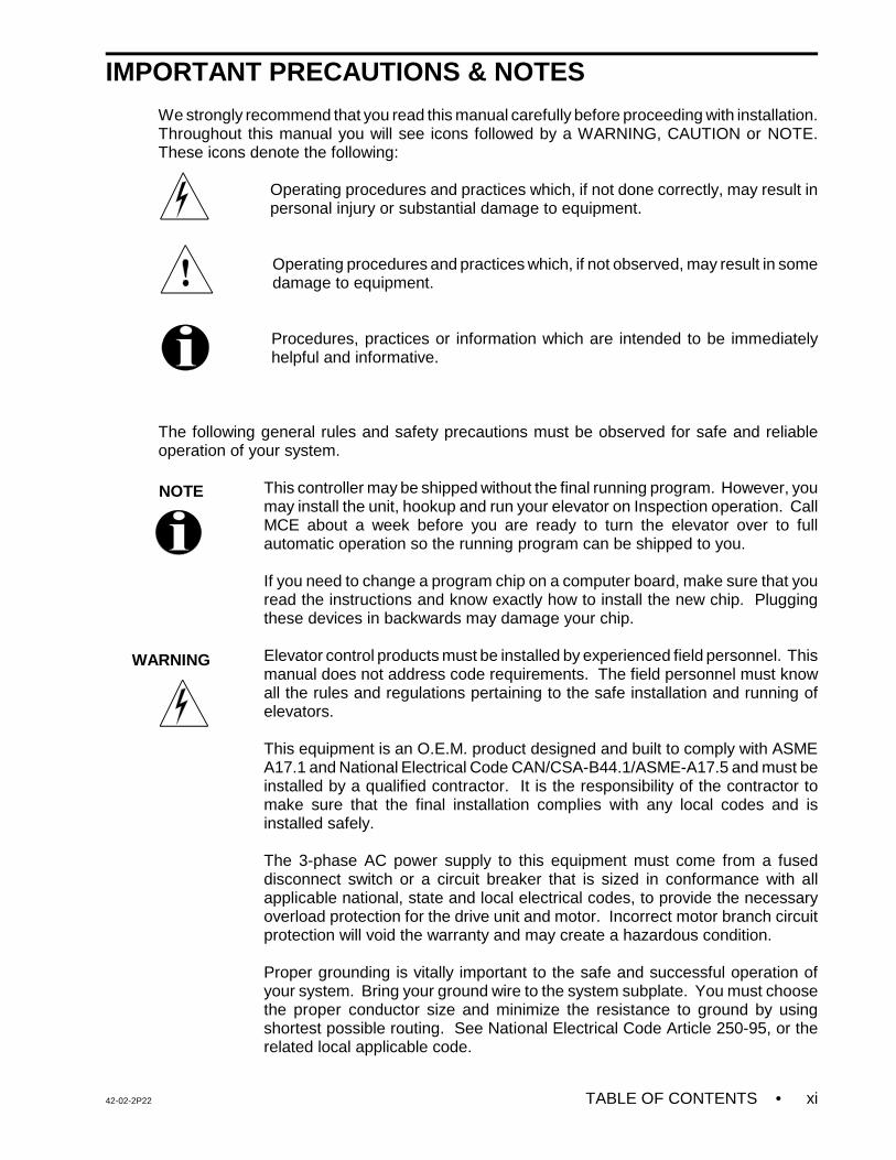
We strongly recommend that you read this manual carefully before proceeding with installation.Throughout this manual you will see icons followed by a WARNING, CAUTION or NOTE.These icons denote the following:
Operating procedures and practices which, if not done correctly, may result inpersonal injury or substantial damage to equipment.
Operating procedures and practices which, if not observed, may result in somedamage to equipment.
Procedures, practices or information which are intended to be immediatelyhelpful and informative.
The following general rules and safety precautions must be observed for safe and reliableoperation of your system.
This controller may be shipped without the final running program. However, youmay install the unit, hookup and run your elevator on Inspection operation. CallMCE about a week before you are ready to turn the elevator over to fullautomatic operation so the running program can be shipped to you.
If you need to change a program chip on a computer board, make sure that youread the instructions and know exactly how to install the new chip. Pluggingthese devices in backwards may damage your chip.
Elevator control products must be installed by experienced field personnel. Thismanual does not address code requirements. The field personnel must knowall the rules and regulations pertaining to the safe installation and running ofelevators.
This equipment is an O.E.M. product designed and built to comply with ASMEA17.1 and National Electrical Code CAN/CSA-B44.1/ASME-A17.5 and must beinstalled by a qualified contractor. It is the responsibility of the contractor tomake sure that the final installation complies with any local codes and isinstalled safely.
The 3-phase AC power supply to this equipment must come from a fuseddisconnect switch or a circuit breaker that is sized in conformance with allapplicable national, state and local electrical codes, to provide the necessaryoverload protection for the drive unit and motor. Incorrect motor branch circuitprotection will void the warranty and may create a hazardous condition.
Proper grounding is vitally important to the safe and successful operation ofyour system. Bring your ground wire to the system subplate. You must choosethe proper conductor size and minimize the resistance to ground by usingshortest possible routing. See National Electrical Code Article 250-95, or therelated local applicable code.
• TABLE OF CONTENTS 42-02-2P22xii
WARNING
CAUTION
NOTE
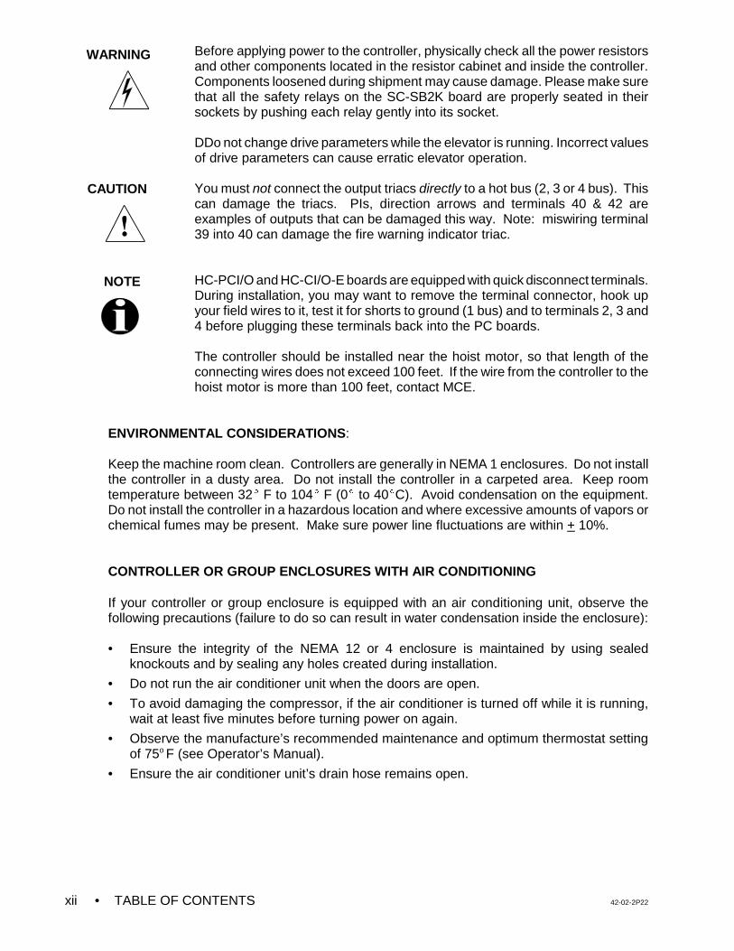
Before applying power to the controller, physically check all the power resistorsand other components located in the resistor cabinet and inside the controller.Components loosened during shipment may cause damage. Please make surethat all the safety relays on the SC-SB2K board are properly seated in theirsockets by pushing each relay gently into its socket.
DDo not change drive parameters while the elevator is running. Incorrect valuesof drive parameters can cause erratic elevator operation.
You must not connect the output triacs directly to a hot bus (2, 3 or 4 bus). Thiscan damage the triacs. PIs, direction arrows and terminals 40 & 42 areexamples of outputs that can be damaged this way. Note: miswiring terminal39 into 40 can damage the fire warning indicator triac.
HC-PCI/O and HC-CI/O-E boards are equipped with quick disconnect terminals.During installation, you may want to remove the terminal connector, hook upyour field wires to it, test it for shorts to ground (1 bus) and to terminals 2, 3 and4 before plugging these terminals back into the PC boards.
The controller should be installed near the hoist motor, so that length of theconnecting wires does not exceed 100 feet. If the wire from the controller to thehoist motor is more than 100 feet, contact MCE.
ENVIRONMENTAL CONSIDERATIONS:
Keep the machine room clean. Controllers are generally in NEMA 1 enclosures. Do not installthe controller in a dusty area. Do not install the controller in a carpeted area. Keep roomtemperature between 32E F to 104E F (0E to 40EC). Avoid condensation on the equipment.Do not install the controller in a hazardous location and where excessive amounts of vapors orchemical fumes may be present. Make sure power line fluctuations are within + 10%.
CONTROLLER OR GROUP ENCLOSURES WITH AIR CONDITIONING
If your controller or group enclosure is equipped with an air conditioning unit, observe thefollowing precautions (failure to do so can result in water condensation inside the enclosure):
• Ensure the integrity of the NEMA 12 or 4 enclosure is maintained by using sealedknockouts and by sealing any holes created during installation.
• Do not run the air conditioner unit when the doors are open.
• To avoid damaging the compressor, if the air conditioner is turned off while it is running,wait at least five minutes before turning power on again.
• Observe the manufacture’s recommended maintenance and optimum thermostat settingof 75o F (see Operator’s Manual).
• Ensure the air conditioner unit’s drain hose remains open.
42-02-2P22 TABLE OF CONTENTS • xiii
LIMITED WARRANTY
Motion Control Engineering (manufacturer) warrants its products for a period of 15 months from the date ofshipment from its factory to be free from defects in workmanship and materials. Any defect appearing more than15 months from the date of shipment from the factory shall be deemed to be due to ordinary wear and tear.Manufacturer, however, assumes no risk or liability for results of the use of the products purchased from it,including, but without limiting the generality of the forgoing: (1) The use in combination with any electrical orelectronic components, circuits, systems, assemblies or any other material or equipment (2) Unsuitability of thisproduct for use in any circuit, assembly or environment. Purchasers’ rights under this warranty shall consistsolely of requiring the manufacturer to repair, or in manufacturer's sole discretion, replace free of charge, F.O.B.factory, any defective items received at said factory within the said 15 months and determined by manufacturerto be defective. The giving of or failure to give any advice or recommendation by manufacturer shall notconstitute any warranty by or impose any liability upon the manufacturer. This warranty constitutes the sole andexclusive remedy of the purchaser and the exclusive liability of the manufacturer, AND IN LIEU OF ANY ANDALL OTHER WARRANTIES, EXPRESSED, IMPLIED, OR STATUTORY AS TO MERCHANTABILITY,FITNESS, FOR PURPOSE SOLD, DESCRIPTION, QUALITY PRODUCTIVENESS OR ANY OTHER MATTER.In no event will the manufacturer be liable for special or consequential damages or for delay in performance ofthis warranty.
Products that are not manufactured by MCE (such as drives, CRT's, modems, printers, etc.) are not coveredunder the above warranty terms. MCE, however, extends the same warranty terms that the originalmanufacturer of such equipment provide with their product (refer to the warranty terms for such products in theirrespective manual).
42-02-2P22 PRODUCT DESCRIPTION • 1-1
SECTION 1PRODUCT DESCRIPTION
1.0 GENERAL INFORMATION
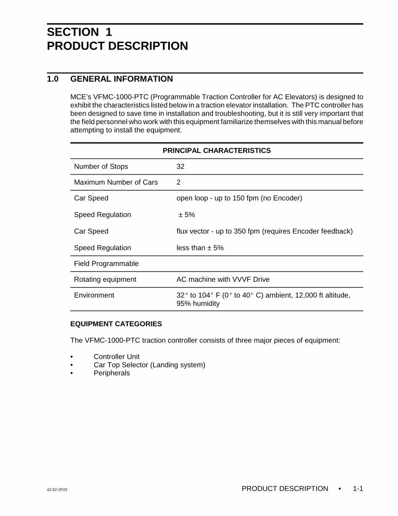
MCE’s VFMC-1000-PTC (Programmable Traction Controller for AC Elevators) is designed toexhibit the characteristics listed below in a traction elevator installation. The PTC controller hasbeen designed to save time in installation and troubleshooting, but it is still very important thatthe field personnel who work with this equipment familiarize themselves with this manual beforeattempting to install the equipment.
PRINCIPAL CHARACTERISTICS
Number of Stops 32
Maximum Number of Cars 2
Car Speed
Speed Regulation
Car Speed
Speed Regulation
open loop - up to 150 fpm (no Encoder)
± 5%
flux vector - up to 350 fpm (requires Encoder feedback)
less than ± 5%
Field Programmable
Rotating equipment AC machine with VVVF Drive
Environment 32E to 104E F (0E to 40E C) ambient, 12,000 ft altitude,95% humidity
EQUIPMENT CATEGORIES
The VFMC-1000-PTC traction controller consists of three major pieces of equipment:
• Controller Unit• Car Top Selector (Landing system)• Peripherals
• PRODUCT DESCRIPTION 42-02-2P221-2
1.1 CAR CONTROLLER PHYSICAL DESCRIPTION
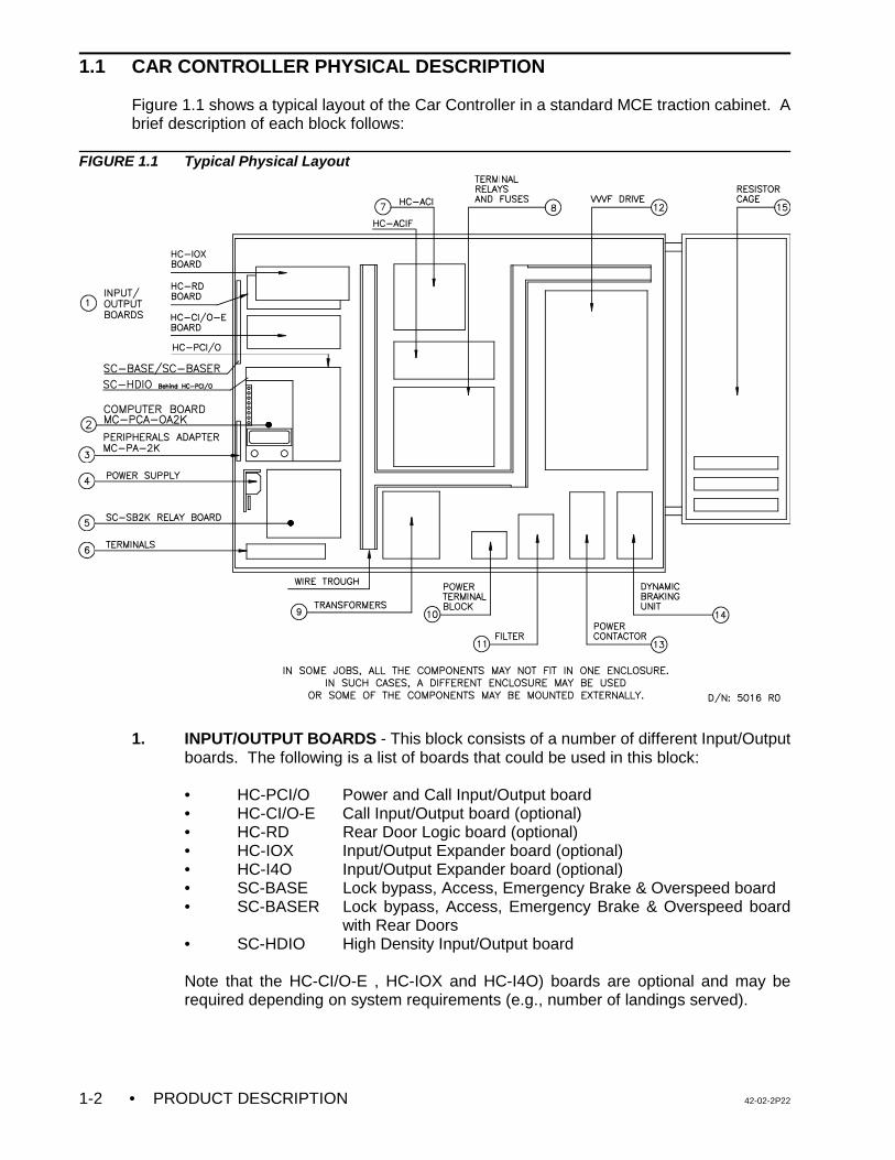
Figure 1.1 shows a typical layout of the Car Controller in a standard MCE traction cabinet. Abrief description of each block follows:
FIGURE 1.1 Typical Physical Layout
1. INPUT/OUTPUT BOARDS - This block consists of a number of different Input/Outputboards. The following is a list of boards that could be used in this block:
• HC-PCI/O Power and Call Input/Output board• HC-CI/O-E Call Input/Output board (optional)• HC-RD Rear Door Logic board (optional)• HC-IOX Input/Output Expander board (optional)• HC-I4O Input/Output Expander board (optional)• SC-BASE Lock bypass, Access, Emergency Brake & Overspeed board• SC-BASER Lock bypass, Access, Emergency Brake & Overspeed board
with Rear Doors• SC-HDIO High Density Input/Output board
Note that the HC-CI/O-E , HC-IOX and HC-I4O) boards are optional and may berequired depending on system requirements (e.g., number of landings served).
42-02-2P22 PRODUCT DESCRIPTION • 1-3
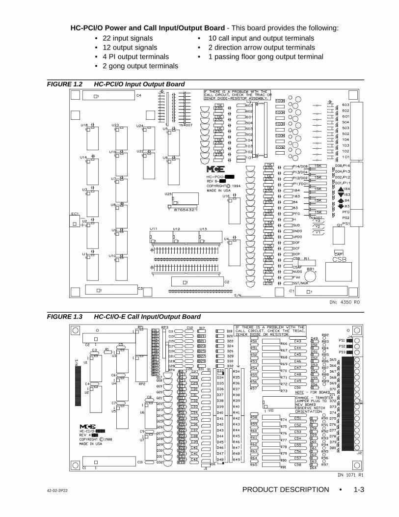
HC-PCI/O Power and Call Input/Output Board - This board provides the following:• 22 input signals • 10 call input and output terminals• 12 output signals • 2 direction arrow output terminals• 4 PI output terminals • 1 passing floor gong output terminal • 2 gong output terminals
FIGURE 1.2 HC-PCI/O Input Output Board
FIGURE 1.3 HC-CI/O-E Call Input/Output Board
• PRODUCT DESCRIPTION 42-02-2P221-4
HC-CI/O-E Call Input/Output Board - This board provides the following:
• 4 PI output terminals • 12 call input and output terminals
HC-RD Rear Door Logic Board - This board (not shown) provides the inputs and outputsrequired for independent rear doors.
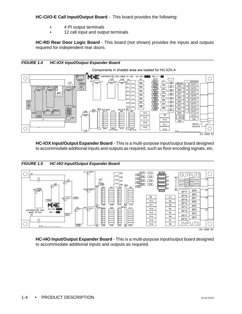
FIGURE 1.4 HC-IOX Input/Output Expander Board
HC-IOX Input/Output Expander Board - This is a multi-purpose input/output board designedto accommodate additional inputs and outputs as required, such as floor encoding signals, etc.
FIGURE 1.5 HC-I4O Input/Output Expander Board
HC-I4O Input/Output Expander Board - This is a multi-purpose input/output board designedto accommodate additional inputs and outputs as required.
42-02-2P22 PRODUCT DESCRIPTION • 1-5
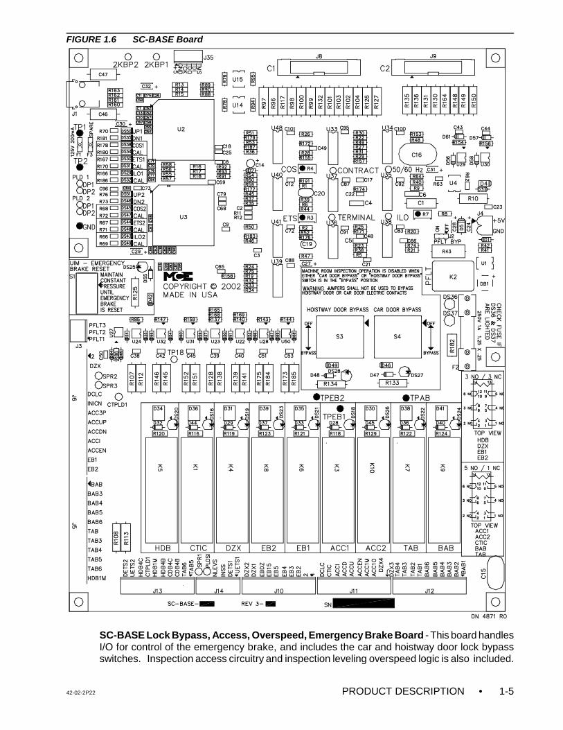
FIGURE 1.6 SC-BASE Board
SC-BASE Lock Bypass, Access, Overspeed, Emergency Brake Board - This board handlesI/O for control of the emergency brake, and includes the car and hoistway door lock bypassswitches. Inspection access circuitry and inspection leveling overspeed logic is also included.
• PRODUCT DESCRIPTION 42-02-2P221-6
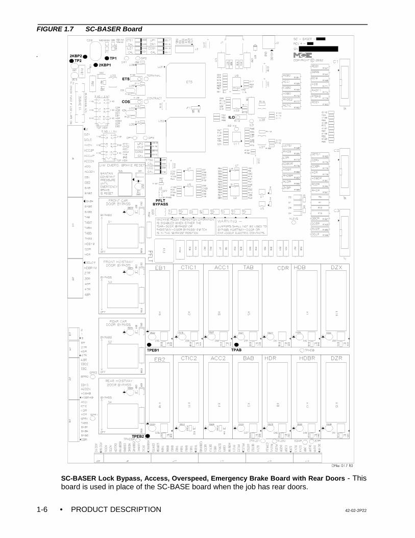
FIGURE 1.7 SC-BASER Board
SC-BASER Lock Bypass, Access, Overspeed, Emergency Brake Board with Rear Doors - Thisboard is used in place of the SC-BASE board when the job has rear doors.
42-02-2P22 PRODUCT DESCRIPTION • 1-7
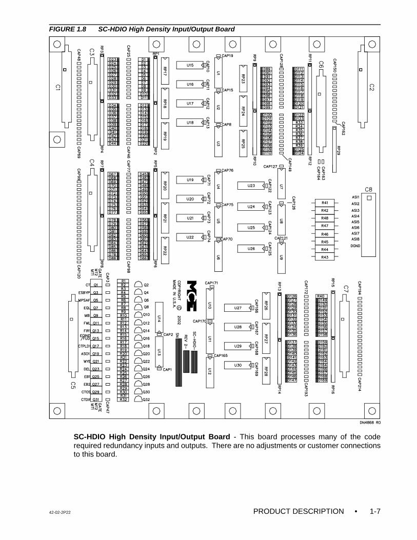
FIGURE 1.8 SC-HDIO High Density Input/Output Board
SC-HDIO High Density Input/Output Board - This board processes many of the coderequired redundancy inputs and outputs. There are no adjustments or customer connectionsto this board.
• PRODUCT DESCRIPTION 42-02-2P221-8
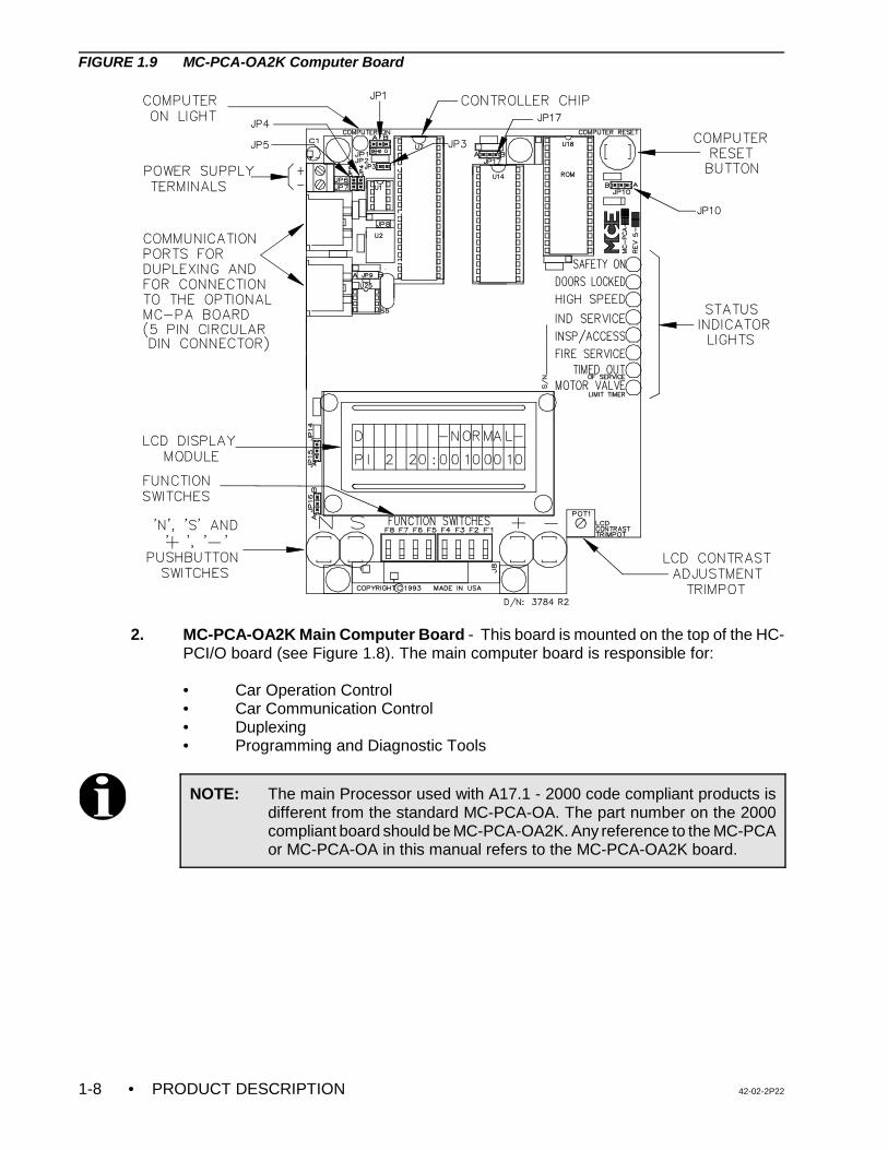
FIGURE 1.9 MC-PCA-OA2K Computer Board
2. MC-PCA-OA2K Main Computer Board - This board is mounted on the top of the HC-PCI/O board (see Figure 1.8). The main computer board is responsible for:
• Car Operation Control• Car Communication Control • Duplexing • Programming and Diagnostic Tools
NOTE: The main Processor used with A17.1 - 2000 code compliant products isdifferent from the standard MC-PCA-OA. The part number on the 2000compliant board should be MC-PCA-OA2K. Any reference to the MC-PCAor MC-PCA-OA in this manual refers to the MC-PCA-OA2K board.
42-02-2P22 PRODUCT DESCRIPTION • 1-9
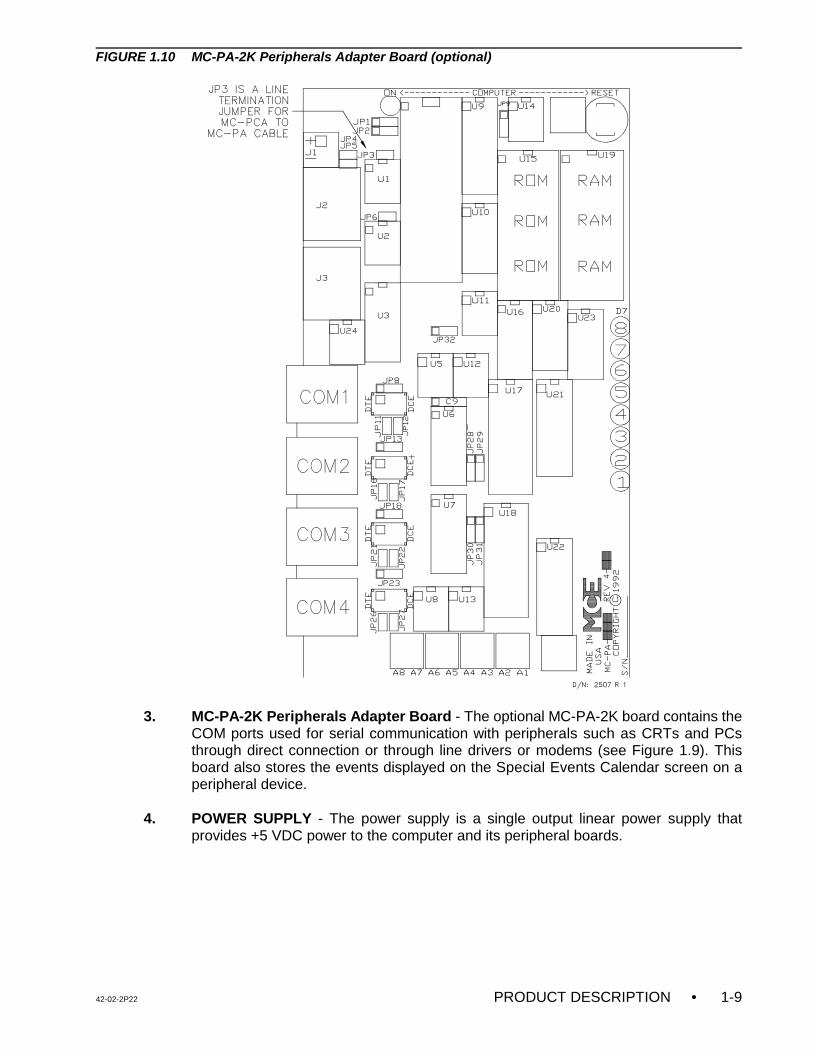
FIGURE 1.10 MC-PA-2K Peripherals Adapter Board (optional)
3. MC-PA-2K Peripherals Adapter Board - The optional MC-PA-2K board contains theCOM ports used for serial communication with peripherals such as CRTs and PCsthrough direct connection or through line drivers or modems (see Figure 1.9). Thisboard also stores the events displayed on the Special Events Calendar screen on aperipheral device.
4. POWER SUPPLY - The power supply is a single output linear power supply thatprovides +5 VDC power to the computer and its peripheral boards.
• PRODUCT DESCRIPTION 42-02-2P221-10
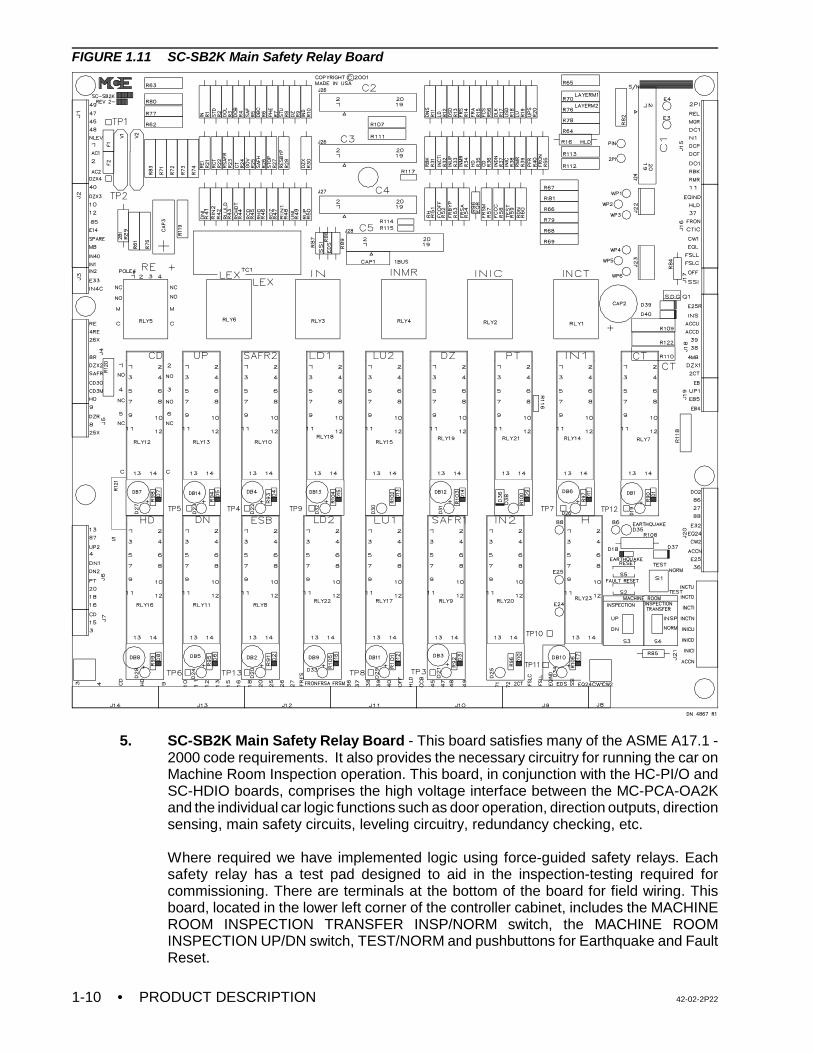
FIGURE 1.11 SC-SB2K Main Safety Relay Board
5. SC-SB2K Main Safety Relay Board - This board satisfies many of the ASME A17.1 -2000 code requirements. It also provides the necessary circuitry for running the car onMachine Room Inspection operation. This board, in conjunction with the HC-PI/O andSC-HDIO boards, comprises the high voltage interface between the MC-PCA-OA2Kand the individual car logic functions such as door operation, direction outputs, directionsensing, main safety circuits, leveling circuitry, redundancy checking, etc.
Where required we have implemented logic using force-guided safety relays. Eachsafety relay has a test pad designed to aid in the inspection-testing required forcommissioning. There are terminals at the bottom of the board for field wiring. Thisboard, located in the lower left corner of the controller cabinet, includes the MACHINEROOM INSPECTION TRANSFER INSP/NORM switch, the MACHINE ROOMINSPECTION UP/DN switch, TEST/NORM and pushbuttons for Earthquake and FaultReset.
42-02-2P22 PRODUCT DESCRIPTION • 1-11
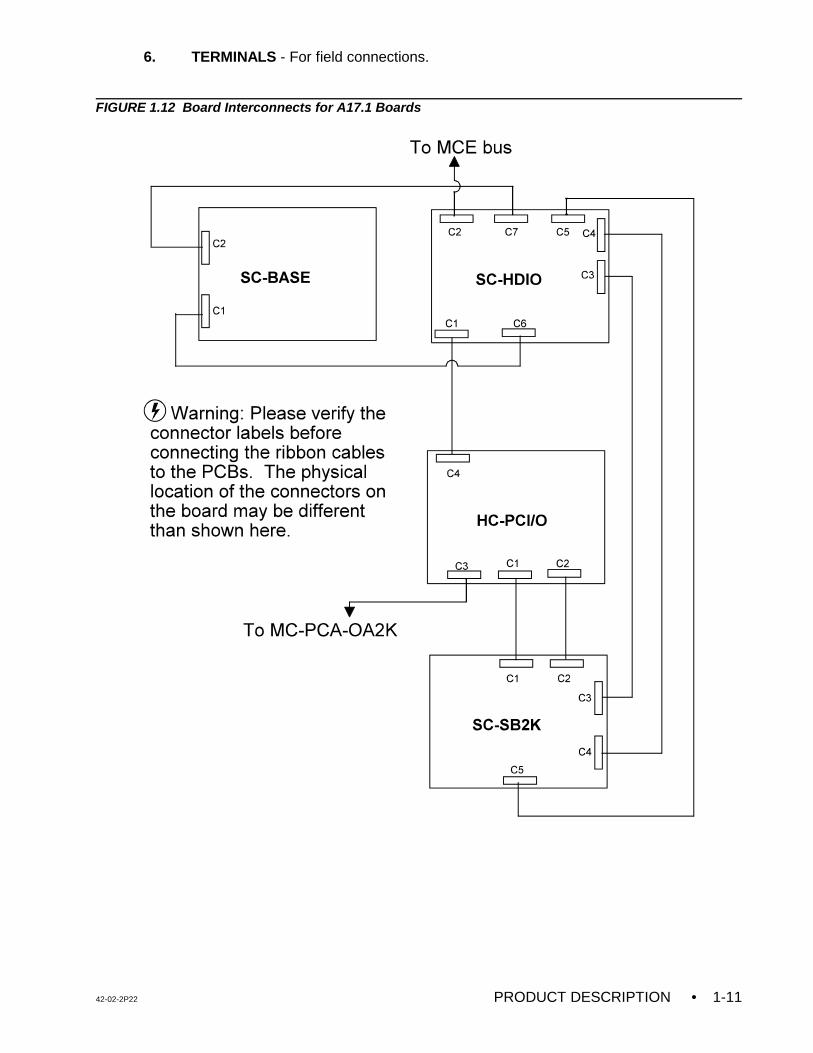
6. TERMINALS - For field connections.
FIGURE 1.12 Board Interconnects for A17.1 Boards
• PRODUCT DESCRIPTION 42-02-2P221-12
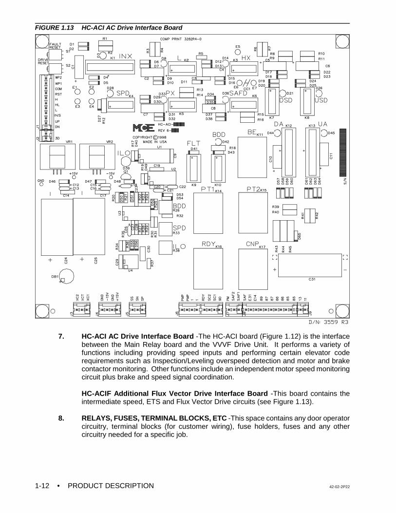
FIGURE 1.13 HC-ACI AC Drive Interface Board
7. HC-ACI AC Drive Interface Board -The HC-ACI board (Figure 1.12) is the interfacebetween the Main Relay board and the VVVF Drive Unit. It performs a variety offunctions including providing speed inputs and performing certain elevator coderequirements such as Inspection/Leveling overspeed detection and motor and brakecontactor monitoring. Other functions include an independent motor speed monitoringcircuit plus brake and speed signal coordination.
HC-ACIF Additional Flux Vector Drive Interface Board -This board contains theintermediate speed, ETS and Flux Vector Drive circuits (see Figure 1.13).
8. RELAYS, FUSES, TERMINAL BLOCKS, ETC -This space contains any door operatorcircuitry, terminal blocks (for customer wiring), fuse holders, fuses and any othercircuitry needed for a specific job.
42-02-2P22 PRODUCT DESCRIPTION • 1-13
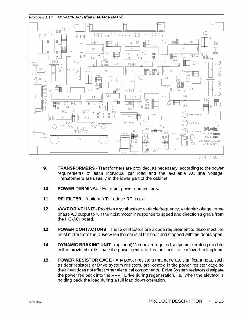
FIGURE 1.14 HC-ACIF AC Drive Interface Board
9. TRANSFORMERS - Transformers are provided, as necessary, according to the powerrequirements of each individual car load and the available AC line voltage.Transformers are usually in the lower part of the cabinet.
10. POWER TERMINAL - For input power connections.
11. RFI FILTER - (optional) To reduce RFI noise.
12. VVVF DRIVE UNIT - Provides a synthesized variable frequency, variable voltage, threephase AC output to run the hoist motor in response to speed and direction signals fromthe HC-ACI board.
13. POWER CONTACTORS - These contactors are a code requirement to disconnect the
hoist motor from the Drive when the car is at the floor and stopped with the doors open.
14. DYNAMIC BRAKING UNIT - (optional) Whenever required, a dynamic braking modulewill be provided to dissipate the power generated by the car in case of overhauling load.
15. POWER RESISTOR CAGE - Any power resistors that generate significant heat, suchas door resistors or Drive system resistors, are located in the power resistor cage sotheir heat does not affect other electrical components. Drive System resistors dissipatethe power fed back into the VVVF Drive during regeneration, i.e., when the elevator isholding back the load during a full load down operation.
• PRODUCT DESCRIPTION 42-02-2P221-14
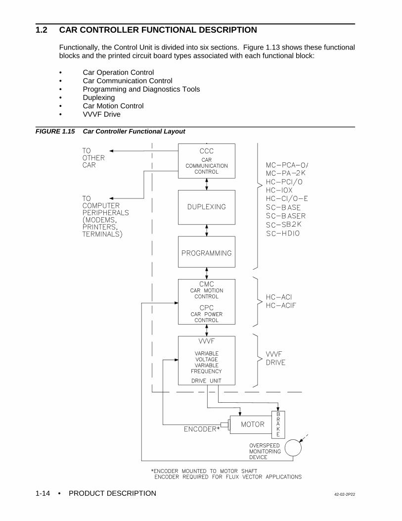
1.2 CAR CONTROLLER FUNCTIONAL DESCRIPTION
Functionally, the Control Unit is divided into six sections. Figure 1.13 shows these functionalblocks and the printed circuit board types associated with each functional block:
• Car Operation Control• Car Communication Control• Programming and Diagnostics Tools• Duplexing• Car Motion Control• VVVF Drive
FIGURE 1.15 Car Controller Functional Layout
42-02-2P22 PRODUCT DESCRIPTION • 1-15
1.2.1 CAR OPERATION CONTROL (COC)
Normal Operation - Normal car operation consists of responding to hall and car call demands,and operating the doors, as required.
Special Operations - The following are special operations controlled by the COC:
• Inspection/Access• Independent Service• Fire Service• Emergency Power• Safety Testing and Redundancy
For details of each operation, see MCE Specifications for Elevator Products. The specialfeatures and options are discussed in Section 5 of this manual.
Discussion of Car Operation Control (COC) - The Car Operation Control (COC) performsthe elevator logic operations for the individual car. These functions are performed by thefollowing circuit boards:
• SC-SB2K Main Safety Relay board• MC-PCA-OA2K Main Processor board• HC-PCI/O Power Input/Output board• HC-CI/O-E Call Input/Output board (optional)• HC-RD Rear Door board (optional)• HC-IOX Input/Output Expander board (optional)• HC-I4O Input/Output Expander board (optional)• SC-BASE Lock Bypass, Access, Emergency Brake and Overspeed board• SC-BASER Lock Bypass, Access, Emergency Brake and Overspeed board with
rear doors• SC-HDIO High Density I/O board
The heart of the COC is the SC-SB2K (Main Safety Relay) board, which makes it possible tomove the car and satisfies code-required safety functions and redundant relay backupfunctions. Except for calls, most of the individual elevator inputs and outputs are handledthrough the Main Safety Relay board and are routed to the HC-PCI/O and HC-HDIO boards,which are the main interface to the MC-PCA-OA2K computer.
Provisions for 4 position indicator outputs are on the HC-PCI/O board. If additional positionindicators are required, HC-PIX boards are added as required. If independent (walk-through)rear doors are required, the HC-RD board acts as the interface between the computer and theRear Door Relay board, which handles all functions associated with the rear doors. Someadditional inputs and outputs such as load weighers are handled through the HC-PCI/O board.Car calls and hall calls are interfaced to the computer through the HC-PCI/O board and HC-CI/O-E boards, which can handle up to 4 landings per board. Therefore, all the input/outputboards (HC-PCI/O, HC-RD, HC-IOX, HC-I4O , SC-HDIO and HC-CI/O-E) act as the interfacebetween the MC-PCA-OA2K Main Computer board and the user. These input/output boardsare linked to the HC-PCI/O and SC-HDIO boards through ribbon cables. The MC-PCA-OA2Kboard contains the main elevator software system that is constantly monitored for correctfunctioning.
• PRODUCT DESCRIPTION 42-02-2P221-16
1.2.2 CAR COMMUNICATION CONTROL (CCC)
The Car Communication Control (CCC) coordinates communication between the individual carcontrollers in a duplex configuration, as well as peripheral devices such as modems, printers,CRT terminals, etc. These functions are performed by the MC-PCA-OA2K Main Computerboard.
1.2.3 PROGRAMMING AND DIAGNOSTICS TOOLS
The PTC is a versatile traction controller and is compatible with most applications. This meansit allows the user to customize the controller to the building requirements after the unit has beeninstalled. The Programming Tool is part of the processing unit (MC-PCA-OA2K computerboard). The list of all of the programmable functions and variables are provided in Section 5of this manual.
1.2.4 DUPLEXING
Each car is capable of seeing the hall calls and at any time performing the duplexing functions,but only one of the cars can process the hall calls and make hall call assignments. If the carthat is performing the duplexing operation goes out of service, the other car will take over thehall call registration and assignment.
1.2.5 CAR MOTION CONTROL (CMC)
The Car Motion Control (CMC) develops the speed command which dictates the car's speed.The speed signal is in the form of step input signals which are applied to the drive unit. Thedrive responds to the commanded step inputs and runs the elevator at predefined speedsettings stored in the drive unit. The CMC also provides for Inspection/Leveling Overspeed(ILO) monitoring and Emergency Terminal Switch (ETS) monitoring. These functions arecovered by the following devices:
• HC-ACI AC Drive Interface board• HC-ACIF Additional Flux Vector Drive Interface board
The HC-ACI board creates the speed command, controls the brake, monitors overspeedconditions, and is the interface between the COC, CPC and the power equipment (brake, ACDrive Unit and supporting devices).
1.2.6 VVVF DRIVE
The VVVF Drive Unit receives the direction(run) and speed command from the HC-ACI board,and provides the proper 3-phase voltage and frequency to create the required RPM and torquein the motor. It also provides dynamic braking when necessary.
1.2.7 TYPICAL SEQUENCE OF OPERATION
To become familiar with the overall sequence of operation of this controller, begin with a carcall input and follow the signals as they progress through various parts of the control system.
At the end of each run the software system checks all force-guided relays for properfunctionality and checks all other safety relay (EPD) devices. Once the checking is completethe main safety relays SAFR1 and SAFR2 are energized.
42-02-2P22 PRODUCT DESCRIPTION • 1-17
A car call is registered by grounding an input on the HC-PCI/O board. This 120VAC signal isconverted to a + 5V logic signal and is then read by the MC-PCA-OA2K Computer board. TheMC-PCA-OA2K board acknowledges this signal by sending a logic signal back to the HC-PCI/Oboard which then turns on a triac to illuminate the call registered light in the car panel and anLED on the HC-PCI/O board.
The MC-PCA-OA2K Computer board determines where the call is in relation to the car positionand sends a direction arrow signal to the HC-PCI/O board which operates an up or down arrowtriac output. This illuminates the correct direction arrow in the car position indicator. No furtheraction can take place unless additional conditions are met. Then, if the doors are closed, theMC-PCA-OA2K Computer board sends the correct direction output signal to the HC-PCI/Oboard, which operates the correct direction triac. This signal is sent to the SC-SB2K MainRelay board which energizes the direction pilot relays. This direction signal then goes to theHC-ACI board and to one or more auxiliary running relays. The direction and high speedcommands originate from the MC-PCA-OA2K board through the HC-PCI/O and the Main Relayboard. The CMC is ready to lift the brake and to provide VFAC Drive Unit control in responseto a speed command that will be provided by the CMC.
In summary, the call signal entered the COC and was processed into direction and high speedacceleration sequence commands. The VFAC speed command and brake signals are thencreated by the CMC and the CPC moves the elevator according to the commanded speed.
1.3 LANDING SYSTEMS
There are two different types of landing systemsthat can be used with VFMC-1000-PTCcontrollers, depending on the customer'spreference: LS-STAN-2K and LS-QUTE-2K.These landing systems are discussed separatelythroughout this manual.
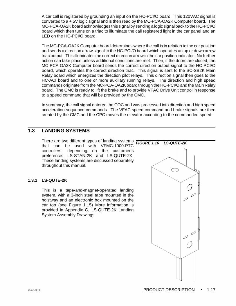
1.3.1 LS-QUTE-2K
This is a tape-and-magnet-operated landingsystem, with a 3-inch steel tape mounted in thehoistway and an electronic box mounted on thecar top (see Figure 1.15) More information isprovided in Appendix G, LS-QUTE-2K LandingSystem Assembly Drawings.
FIGURE 1.16 LS-QUTE-2K
• PRODUCT DESCRIPTION 42-02-2P221-18
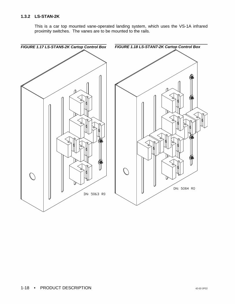
1.3.2 LS-STAN-2K
This is a car top mounted vane-operated landing system, which uses the VS-1A infraredproximity switches. The vanes are to be mounted to the rails.
FIGURE 1.17 LS-STAN5-2K Cartop Control Box FIGURE 1.18 LS-STAN7-2K Cartop Control Box
42-02-2P22 INSTALLATION • 2-1
SECTION 2INSTALLATION
2.0 GENERAL INFORMATION
This section contains important recommendations and instructions for site selection,environmental considerations, installation guidelines and other factors that will help ensure asuccessful installation.
2.0.1 SITE SELECTION
In choosing a proper location for the control equipment, the factors listed below should beconsidered.
• Provide adequate working space for comfort and efficiency.
• Mount the controller in a logical location, taking into consideration the location of otherequipment in the machine room and proper routing of electrical power and controlwiring. Note that MCE controllers do not require rear access.
• Do not install equipment in a hazardous location.
• Provide space for future expansion, if possible.
• Install a telephone in the machine room. Remote diagnostics are available via thetelephone which make start-up and adjustment assistance easier to obtain.
• If any areas in the machine room are subject to vibration, they should be avoided orreinforced to prevent equipment from being adversely affected.
• Provide adequate lighting for the control cabinets and machines. A good working spacesuch as a workbench or table should also be provided.
• The location of the Drive Isolation Transformer is flexible, however, wiring is reducedif it is located near the controller.
2.0.2 ENVIRONMENTAL CONSIDERATIONS
The following are some important environmental considerations that will help to provide for thelongevity of the elevator equipment and reduce maintenance requirements.
• The ambient temperature should not exceed 32E to 104E Fahrenheit (0E - 40E Celsius).Higher ambient temperatures are possible, but not recommended because it willshorten the life of the equipment. Adequate ventilation and possibly air conditioning maybe required.
• The air in the machine room should be free of excessive dust, corrosive atmosphere orexcessive moisture to avoid condensation. A NEMA 4 or NEMA 12 enclosure wouldhelp meet these requirements. If open windows exist in the machine room, it ispreferable to place cabinets away from these windows so that severe weather does notdamage the equipment.
• INSTALLATION 42-02-2P222-2
• High levels of radio frequency (RF) radiation from nearby sources may causeinterference to the computers and other parts of the control system. Using hand-heldcommunication devices in close proximity to the computers may also causeinterference. The controller is designed to EN12015 and EN12016 RFI susceptibilityand radiation standards.
• Power line fluctuation should not be greater than ±10%.
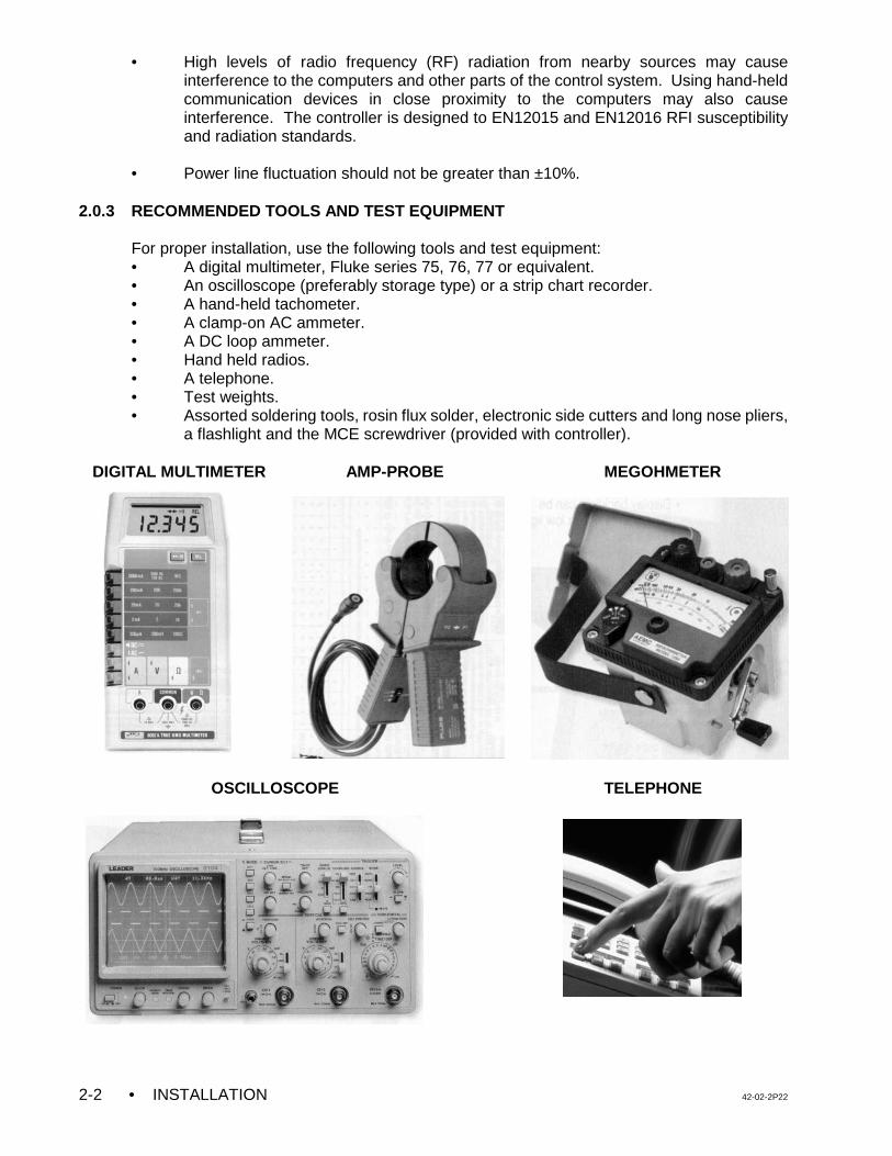
2.0.3 RECOMMENDED TOOLS AND TEST EQUIPMENT
For proper installation, use the following tools and test equipment:• A digital multimeter, Fluke series 75, 76, 77 or equivalent.• An oscilloscope (preferably storage type) or a strip chart recorder.• A hand-held tachometer.• A clamp-on AC ammeter.• A DC loop ammeter.• Hand held radios.• A telephone.• Test weights.• Assorted soldering tools, rosin flux solder, electronic side cutters and long nose pliers,
a flashlight and the MCE screwdriver (provided with controller).
DIGITAL MULTIMETER AMP-PROBE MEGOHMETER
OSCILLOSCOPE TELEPHONE
42-02-2P22 INSTALLATION • 2-3
NOTE: DRAWING NAME - Some drawings have a drawing name directly abovethe title block or at the top of the drawing. The drawing name may be usedto refer to a particular drawing.
2.0.4 WIRING PRINTS
Become familiar with the following information as well as the wiring prints provided with thiscontrol system.
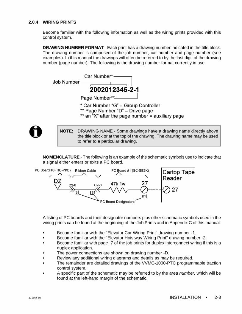
DRAWING NUMBER FORMAT - Each print has a drawing number indicated in the title block.The drawing number is comprised of the job number, car number and page number (seeexamples). In this manual the drawings will often be referred to by the last digit of the drawingnumber (page number). The following is the drawing number format currently in use.
NOMENCLATURE - The following is an example of the schematic symbols use to indicate thata signal either enters or exits a PC board.
A listing of PC boards and their designator numbers plus other schematic symbols used in thewiring prints can be found at the beginning of the Job Prints and in Appendix C of this manual.
• Become familiar with the "Elevator Car Wiring Print" drawing number -1.• Become familiar with the "Elevator Hoistway Wiring Print" drawing number -2.• Become familiar with page -7 of the job prints for duplex interconnect wiring if this is a
duplex application.• The power connections are shown on drawing number -D.• Review any additional wiring diagrams and details as may be required.• The remainder are detailed drawings of the VVMC-1000-PTC programmable traction
control system.• A specific part of the schematic may be referred to by the area number, which will be
found at the left-hand margin of the schematic.
• INSTALLATION 42-02-2P222-4
NOTE: It is strongly recommended that you review the wiring guidelines in sections2.1.1 and 2.2 before bringing wires into the controller.
CAUTION: Do not allow any metal chips to fall into the electronics.
Keep the covers on the AC Drive while wiring to prevent damage to thecomponents.
NOTE: Pay very close attention to the hierarchy of the inspection inputs. In order tomaintain safe operation of the lift while on access, car top or in car inspection,the inspection circuits must be wired as shown in the prints.
CAUTION: Power conductors from the fused disconnect, isolation transformer orother high voltage, high current conductors must be separated from thecontrol wires. It is essential that the Encoder and Speed Sensor wiresbe placed in a separate conduit, away from high current conductors.
2.1 CONTROLLER INSTALLATION
Mount the controller(s) securely to the machine room floor and cut holes to permit bringing thewires into the cabinet as shown in Figure 2.2. There may be labels in the cabinet to help identifylocations for wiring holes. Note that the standard MCE car control cabinet does not require rearaccess. Also, the doors are reversible and removable for ease of wiring.
2.1.1 CONTROLLER WIRING GUIDELINES
Figure 2.2 shows the recommended routing for the field wiring. Observe the following:
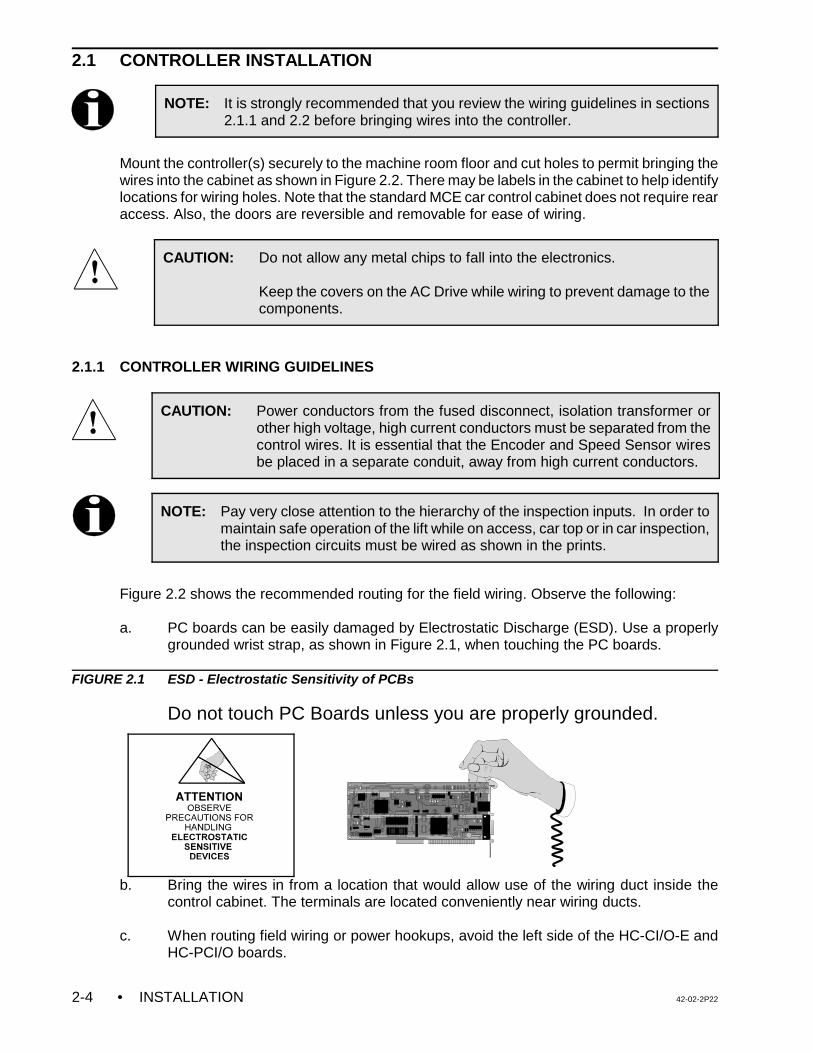
a. PC boards can be easily damaged by Electrostatic Discharge (ESD). Use a properlygrounded wrist strap, as shown in Figure 2.1, when touching the PC boards.
FIGURE 2.1 ESD - Electrostatic Sensitivity of PCBs
Do not touch PC Boards unless you are properly grounded.
b. Bring the wires in from a location that would allow use of the wiring duct inside thecontrol cabinet. The terminals are located conveniently near wiring ducts.
c. When routing field wiring or power hookups, avoid the left side of the HC-CI/O-E and
HC-PCI/O boards.
42-02-2P22 INSTALLATION • 2-5
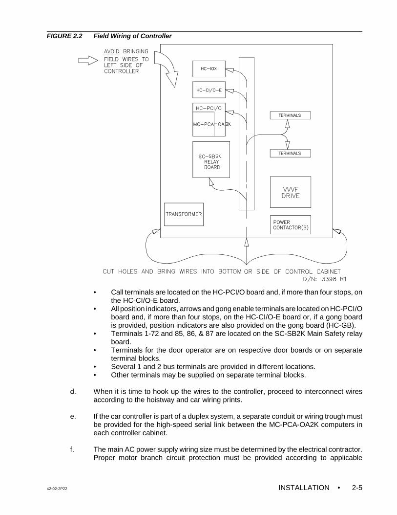
FIGURE 2.2 Field Wiring of Controller
• Call terminals are located on the HC-PCI/O board and, if more than four stops, onthe HC-CI/O-E board.
• All position indicators, arrows and gong enable terminals are located on HC-PCI/Oboard and, if more than four stops, on the HC-CI/O-E board or, if a gong boardis provided, position indicators are also provided on the gong board (HC-GB).
• Terminals 1-72 and 85, 86, & 87 are located on the SC-SB2K Main Safety relayboard.
• Terminals for the door operator are on respective door boards or on separateterminal blocks.
• Several 1 and 2 bus terminals are provided in different locations.• Other terminals may be supplied on separate terminal blocks.
d. When it is time to hook up the wires to the controller, proceed to interconnect wiresaccording to the hoistway and car wiring prints.
e. If the car controller is part of a duplex system, a separate conduit or wiring trough mustbe provided for the high-speed serial link between the MC-PCA-OA2K computers ineach controller cabinet.
f. The main AC power supply wiring size must be determined by the electrical contractor.Proper motor branch circuit protection must be provided according to applicable
• INSTALLATION 42-02-2P222-6
electrical code by using a fused disconnect switch or a circuit breaker for each elevator.Each disconnect or breaker must be clearly labeled with the elevator number.
g. If the car is part of a duplex system, there are a number of details relating to the wiringof the interconnects between the individual cars. They are as follows:
1. The wiring details for the high-speed communication link are fully detailed in thedrawing titled "Instructions for Connection of High Speed CommunicationCables" in the job prints. Follow these instructions exactly. Again, note therequirement for routing the high-speed interconnect cables through a separateconduit or wiring trough.
2. If applicable, also wire according to the drawing titled "Duplex Interconnects toIndividual Car Cabinets" in the job prints. Make sure to ground all of the cabinetsaccording to Section 2.2.1.
2.2 GENERAL WIRING GUIDELINES
Basic wiring practices and grounding requirements are discussed in this section.
2.2.1 GROUND WIRING
To obtain proper grounding, quality wiring materials and methods should be used.
All grounding in the elevator system must conform to all applicable codes. Proper groundingis essential for system safety and helps to reduce noise-induced problems. The following aresome grounding guidelines:
• The grounding wire to the equipment cabinet should be as large as, or larger than, theprimary AC power feeders for the controller and should be as short as possible.
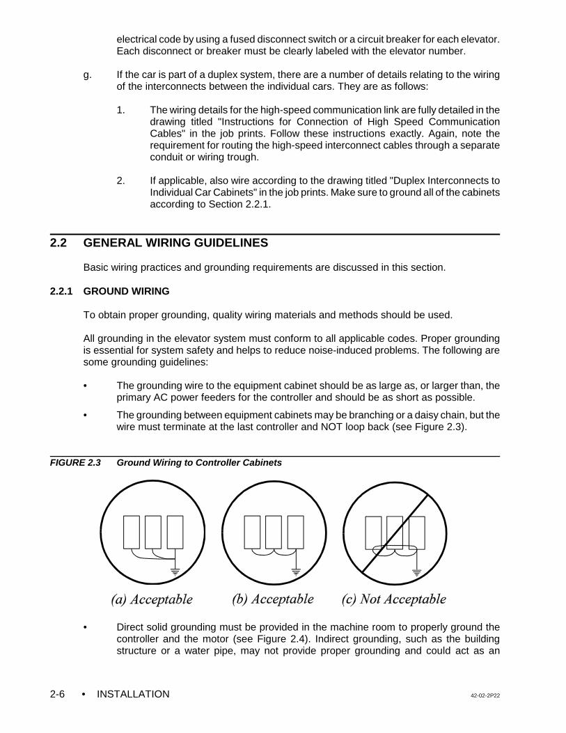
• The grounding between equipment cabinets may be branching or a daisy chain, but thewire must terminate at the last controller and NOT loop back (see Figure 2.3).
FIGURE 2.3 Ground Wiring to Controller Cabinets
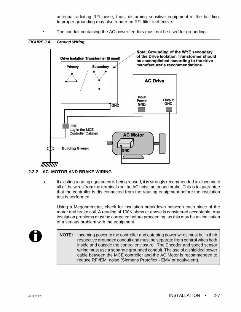
• Direct solid grounding must be provided in the machine room to properly ground thecontroller and the motor (see Figure 2.4). Indirect grounding, such as the buildingstructure or a water pipe, may not provide proper grounding and could act as an
42-02-2P22 INSTALLATION • 2-7
NOTE: Incoming power to the controller and outgoing power wires must be in theirrespective grounded conduit and must be separate from control wires bothinside and outside the control enclosure. The Encoder and speed sensorwiring must use a separate grounded conduit. The use of a shielded powercable between the MCE controller and the AC Motor is recommended toreduce RFI/EMI noise (Siemens Protoflex - EMV or equivalent).
antenna radiating RFI noise, thus, disturbing sensitive equipment in the building.Improper grounding may also render an RFI filter ineffective.
• The conduit containing the AC power feeders must not be used for grounding.
FIGURE 2.4 Ground Wiring
2.2.2 AC MOTOR AND BRAKE WIRING
a. If existing rotating equipment is being reused, it is strongly recommended to disconnectall of the wires from the terminals on the AC hoist motor and brake. This is to guaranteethat the controller is dis-connected from the rotating equipment before the insulationtest is performed.
Using a Megohmmeter, check for insulation breakdown between each piece of themotor and brake coil. A reading of 100K ohms or above is considered acceptable. Anyinsulation problems must be corrected before proceeding, as this may be an indicationof a serious problem with the equipment.
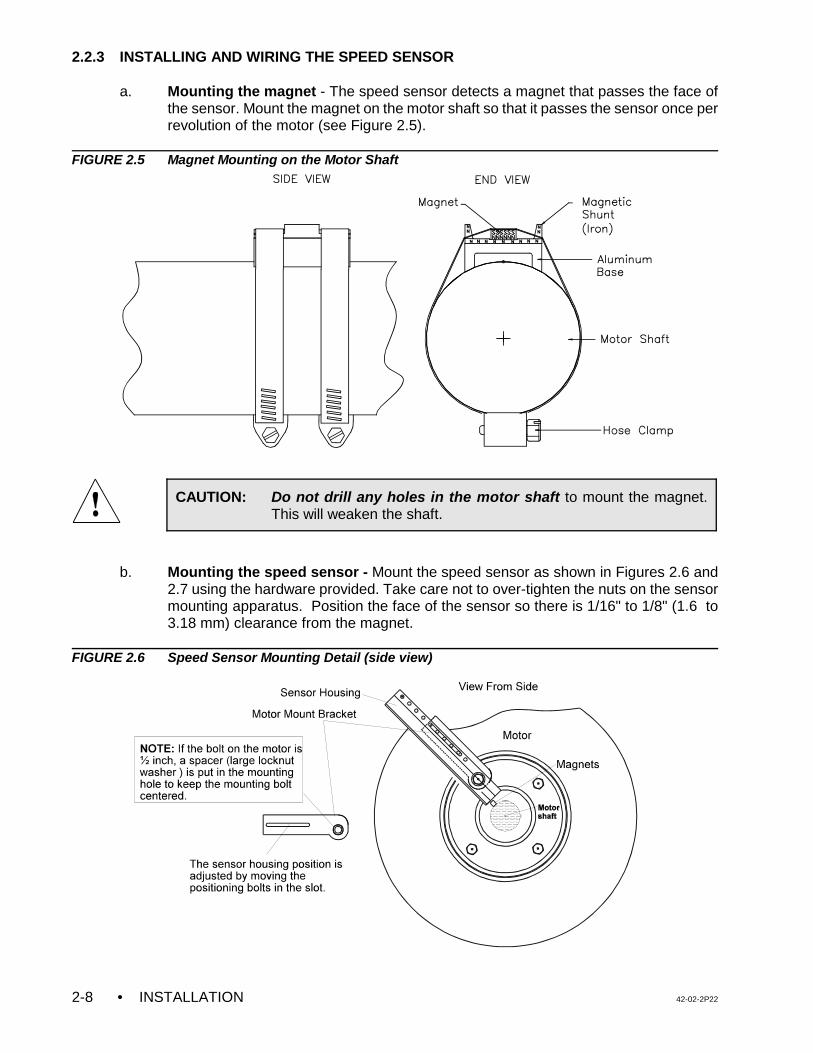
• INSTALLATION 42-02-2P222-8
CAUTION: Do not drill any holes in the motor shaft to mount the magnet.This will weaken the shaft.
2.2.3 INSTALLING AND WIRING THE SPEED SENSOR
a. Mounting the magnet - The speed sensor detects a magnet that passes the face ofthe sensor. Mount the magnet on the motor shaft so that it passes the sensor once perrevolution of the motor (see Figure 2.5).
FIGURE 2.5 Magnet Mounting on the Motor Shaft
b. Mounting the speed sensor - Mount the speed sensor as shown in Figures 2.6 and2.7 using the hardware provided. Take care not to over-tighten the nuts on the sensormounting apparatus. Position the face of the sensor so there is 1/16" to 1/8" (1.6 to3.18 mm) clearance from the magnet.
FIGURE 2.6 Speed Sensor Mounting Detail (side view)
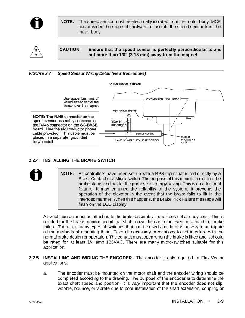
42-02-2P22 INSTALLATION • 2-9
NOTE: The speed sensor must be electrically isolated from the motor body. MCEhas provided the required hardware to insulate the speed sensor from themotor body
CAUTION: Ensure that the speed sensor is perfectly perpendicular to andnot more than 1/8" (3.18 mm) away from the magnet.
NOTE: All controllers have been set up with a BPS input that is fed directly by aBrake Contact or a Micro-switch. The purpose of this input is to monitor thebrake status and not for the purpose of energy saving. This is an additionalfeature. It may enhance the reliability of the system. It prevents theoperation of the elevator in the event that the brake fails to lift in theintended manner. When this happens, the Brake Pick Failure message willflash on the LCD display.
FIGURE 2.7 Speed Sensor Wiring Detail (view from above)
2.2.4 INSTALLING THE BRAKE SWITCH
A switch contact must be attached to the brake assembly if one does not already exist. This isneeded for the brake monitor circuit that shuts down the car in the event of a machine brakefailure. There are many types of switches that can be used and there is no way to anticipateall the methods of mounting them. Take all necessary precautions to not interfere with thenormal brake design or operation. The contact must open when the brake is lifted and it shouldbe rated for at least 1/4 amp 125VAC. There are many micro-switches suitable for thisapplication.
2.2.5 INSTALLING AND WIRING THE ENCODER - The encoder is only required for Flux Vectorapplications.
a. The encoder must be mounted on the motor shaft and the encoder wiring should becompleted according to the drawing. The purpose of the encoder is to determine theexact shaft speed and position. It is very important that the encoder does not slip,wobble, bounce, or vibrate due to poor installation of the shaft extension, coupling or
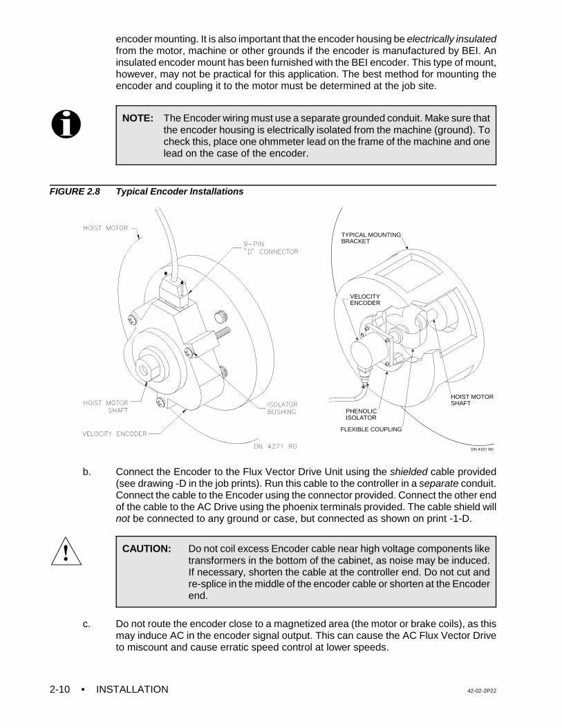
• INSTALLATION 42-02-2P222-10
NOTE: The Encoder wiring must use a separate grounded conduit. Make sure thatthe encoder housing is electrically isolated from the machine (ground). Tocheck this, place one ohmmeter lead on the frame of the machine and onelead on the case of the encoder.
CAUTION: Do not coil excess Encoder cable near high voltage components liketransformers in the bottom of the cabinet, as noise may be induced.If necessary, shorten the cable at the controller end. Do not cut andre-splice in the middle of the encoder cable or shorten at the Encoderend.
VELOCITYENCODER
PHENOLICISOLATOR
FLEXIBLE COUPLING
TYPICAL MOUNTINGBRACKET
HOIST MOTORSHAFT
DN 4107 R0
encoder mounting. It is also important that the encoder housing be electrically insulatedfrom the motor, machine or other grounds if the encoder is manufactured by BEI. Aninsulated encoder mount has been furnished with the BEI encoder. This type of mount,however, may not be practical for this application. The best method for mounting theencoder and coupling it to the motor must be determined at the job site.
FIGURE 2.8 Typical Encoder Installations
b. Connect the Encoder to the Flux Vector Drive Unit using the shielded cable provided(see drawing -D in the job prints). Run this cable to the controller in a separate conduit.Connect the cable to the Encoder using the connector provided. Connect the other endof the cable to the AC Drive using the phoenix terminals provided. The cable shield willnot be connected to any ground or case, but connected as shown on print -1-D.
c. Do not route the encoder close to a magnetized area (the motor or brake coils), as thismay induce AC in the encoder signal output. This can cause the AC Flux Vector Driveto miscount and cause erratic speed control at lower speeds.
42-02-2P22 INSTALLATION • 2-11
2.3 HOISTWAY CONTROL EQUIPMENT INSTALLATION
This section covers the recommended procedures for installing the landing system, terminalslowdown switches, directional limit switches, hoistway access switches (if required), thehoistway access limit switch, and the emergency terminal slowdown switch.
2.3.1 INSTALLING THE LANDING SYSTEM - Refer to the installation drawings for the type oflanding system provided.
2.3.2 INSTALLING THE HOISTWAY LIMIT SWITCHES
a. The terminal landing slowdown switches should be installed and adjusted to openapproximately two inches beyond the point where a normal slowdown is initiated.
b. The direction limit switches should be installed and adjusted to open approximately oneinch beyond the terminal landing.
c. The emergency terminal slowdown switch (if required) should open approximately 50%of the slowdown distance from the terminal. This switch should be installed andadjusted to achieve the required operation according to the applicable elevator code.
d. Make sure that the cam that operates the slowdown and limit switches maintains theterminal slowdown switch open until the direction limit switch and emergency terminalslowdown switches (if required) are open.
e. Make sure that the terminal slowdown, direction limit and emergency terminal slowdownswitches are held open for the entire runby or overtravel of the elevator.
f. The hoistway access limit switch (if required) should be installed and adjusted to openand stop the elevator in the down direction when the top of the elevator is approximatelylevel with the top landing (when the top hoistway access switch is activated while onAccess or Inspection operation).
g. For faster geared elevators, the face of the cam operating the limit switches must besufficiently gradual so that the impact of the switch rollers striking the cam is relativelysilent.
2.3.3 INSTALLING THE LANDING SYSTEM CONTROL BOX (LS-QUTE) - Refer to the drawingsin the job prints.
• The location for the landing system box should have already been selected.
• Holes are available on both sides and on the bottom of the landing system box formounting to any support brackets or structural channels. The mounting of the boxshould be very firm and solid so that knocking it out of alignment should be difficult. Use1/4-20 hardware.
• To install the tape into the tape guides on the LS-QUTE landing system box, removethe 2 thumbscrews on the 2 guide assemblies, insert the tape and reinstall the guideswith the thumbscrews (tighten firmly). If the installation has the LS-QUTE car topselector with the additional sensor bracket on the rear of the tape, first remove the three8-32 screws holding the protective 1" wide channel. This channel covers the back of theDoor Zone sensors on the upper tape guide bracket. Remove the single standoff thatis in the way of the thumbscrew holding the tape guide. Remove the thumbscrews
• INSTALLATION 42-02-2P222-12
holding the upper and lower tape guides, insert the tape, and reinstall the guides withthe thumbscrews (tighten firmly). Reinstall the standoff (do not over-tighten) and theprotective channel.
• After inserting the steel tape into the tape guides, check the location of the landingsystem box. The car should be at the top of the hoistway to make it easier to see if thealignment is causing any stress or binding on the tape guides. Make sure that the boxis vertical and plumb with the tape. This allows for easy tape movement and avoidsexcessive wear on the tape guides (using a level is helpful). Be careful so as to avoidpremature failure of the tape guides.
• Move the elevator to the top and bottom of the hoistway to check for smooth tapemovement and to make sure that there is no excessive pressure on the tape guides.Correct any problems immediately.
2.3.4 INSTALLING THE MAGNETIC STRIPS ON THE STEEL TAPE
a. Carefully, read and follow the Magnet Installation instructions in the job prints, but readthe rest of these instructions before proceeding.
b. Before installing the magnets, clean the steel tape thoroughly with an appropriatesolvent. No oil should be left on the tape as it will interfere with the adhesive backingon the magnets.
c. There are normally five lanes of magnets installed on the side of the tape facing the car.One lane consists of only the LU/DZ/LD and requires that a 6-inch magnet be installedat each floor. The other lanes have magnets which initiate slow downs.
d. If the installation has rear doors, it may have an LS-QUTE landing system which hasadditional Door Zone sensors on the rear of the upper tape guide assembly. Follow theMagnet Installation instructions in the job prints and install the front and rear Door Zonemagnets on the steel tape as shown.
2.3.5 DZX SWITCH
Depending on the type of landing system selector you have purchased we have installed asecond door zone sensor called DZX. For the LS-STAN-X system a second vane switch isinstalled in the center door zone lane. On the LS-QUTE system a third door zone sensor isplaced between the existing DZ sensors in the center lane. Since the DZX signal needs to berouted to the controller (SC-BASE board) you will need to connect DZX to your traveler.
2.3.6 TM SWITCH WIRING AND ADJUSTMENT (IF USED)
Refer to the drawing titled "Elevator Car Wiring Print" in the job prints for details on the wiringand setting of each contact in the TM switch. Carefully examine the functioning of this switch,especially if copper-to-carbon contacts are used. The current levels are quite low and may notbe enough to burn the oxide off the contacts.
2.3.7 DOOR OPERATOR DIODE INSTALLATION (IF USED)
Certain door operators, such as G.A.L. models MOM or MOH, require the installation of diodesin the door operator on the car top. See the drawing titled "Elevator Car Wiring Print" in the jobprints for any special instructions regarding these diodes.
42-02-2P22 INSTALLATION • 2-13
2.3.8 DOOR POSITION MONITOR SWITCH (IF USED)
If you are in a jurisdiction where ASME A17.1 - 1996 or later is being enforced, Door PositionMonitor switch(s) connected to the DPM and/or DPMR inputs, must be added to monitor theposition of the closed doors. This must be a separate physical limit switch that makes upapproximately 1 to 2 inches before the doors lock.
42-02-2P22 START-UP • 3-1
NOTE: A short to ground is defined as having a resistance of less than 20 ohmsbetween the 1-bus (common) and the terminal being checked.
NOTE: If existing rotating equipment is being reused, it is strongly recommendedto disconnect all of the wires from the terminals on the AC hoist motor andbrake. This is to guarantee that the controller is dis-connected from therotating equipment before the insulation test is performed. Using aMegohmmeter, check for insulation breakdown between the frame of eachpiece of equipment and it's associated stator terminals and the brake fieldterminals. A reading of 100K ohms or above is considered acceptable. Anyinsulation problems must be corrected before proceeding, as this may bean indication of a serious problem with the equipment.
SECTION 3START-UP
3.0 GENERAL INFORMATION
In this section, the car will be prepared for use by construction personnel so that they maycomplete the elevator installation. At this time the speed sensor must be properly installed asdescribed in Section 2.2.3. This section will cover the sequence of applying power to thecontroller and associated components, the AC hoist motor and brake, and completing the initialadjustment of the system to get basic car movement on Inspection operation.
3.1 GROUND CHECK
Conduct a ground test before powering up the system. Refer to Figure 1.1 and Figure 2.2 tohelp locate items as they are referred to in the ground check.
a. Remove fuse F4 in the individual car controller cabinet. If the system is a duplex,consult the schematics and remove the fuse that powers terminal 2H and the fuse thatpowers terminal 2F, if present.
b. Check for shorts to ground on all terminals on the bottom of the SC-SB2K Main Relayboard.
c. Check for shorts to ground on all terminals on the HC-PCI/O and HC-CI/O-E boards.
d. Check for shorts to ground on terminals F1, F2, A1, A2, and D5. If a G.A.L. MOD dooroperator is provided, remove door fuses F7 and F8. For other door operators, consultthe prints as to which fuses to remove, then check the appropriate terminals for shortsto ground.
e. Check for shorts to ground on motor power terminals T1, T2 and T3. Also check forground on brake terminals B1 and B2.
In the following instructions it is assumed that the hoist ropes are attached to the car sling, allhoistway doors are closed (but not necessarily locked), and all hoistway and machine roomwiring is complete. The car safety must be adjusted to the manufacturer’s specifications, thegovernor installed and the governor rope attached to the car safety. Correct any malfunctionbefore proceeding further.
• START-UP 42-02-2P223-2
WARNING: These instructions assume the elevator mechanic has adequateelectrical troubleshooting experience. Follow the procedures carefullyand if the elevator does not respond correctly, check the circuits anduse the troubleshooting section in this manual (Section 6). Proceedcautiously. To become familiar with the procedure, read theseinstructions all the way through before starting the work.
WARNING: This equipment contains rotating parts on motors and driven machinesand voltages that may be as high as 800 volts. High voltage and moving parts cancause serious or fatal injury. Only qualified personnel familiar with this manual andany driven machinery should attempt to start-up or troubleshoot this equipment.Observe these precautions:
a. USE EXTREME CAUTION: DO NOT TOUCH any circuit board, the VFAC Drive,or a motor electrical connection without making sure that the unit is properlygrounded and that no high voltage is present. DO NOT apply AC power beforegrounding per instructions herein.
b. Improper control operation may cause violent motion of the motor shaft anddriven equipment. Be certain that unexpected motor shaft movement will notcause injury to personnel or damage to equipment. Peak torques of severaltimes rated motor torque can occur during a control failure.
c. The VFAC Drive, the AC motor, the braking unit and the field circuits may havehigh voltage present whenever AC power is applied, even when the motor is notrotating.
d. Make sure to use SHIELDED CABLE for the speed sensor, and wire it exactlyas shown. Make sure to ground the controller cabinet according to local code.
3.2 BEFORE APPLYING POWER
Before applying power to the controller, perform the following:
a. Physically check all of the power resistors and any other components located in theresistor enclosure and inside the controller. Any components loosened during shipmentmay cause damage.
b. Remove one side of the ribbon cable connecting the SC-SB2K board to the HC-PCI/Oboard at connector C1 by pushing open the two latches.
c. Unplug the screw terminal blocks from the HC-PCI/O and any HC-CI/O-E, HC-IOX orHC-I4O boards by moving the blocks to the right. This is done to avoid damaging theboards by accidentally shorting one of the output devices to one of the power buses(terminals 2, 3, or 4) during the initial power-up of the system.
MCE's VFMC-1000-PTC controller is designed to be able to operate on Inspection and Accesswithout the computers hooked up during start-up.
3.3 APPLYING POWER - PREPARING TO MOVE THE CAR ON INSPECTION
42-02-2P22 START-UP • 3-3
WARNING: If the wire to terminal ACCN (or INICN) is not removed (step ‘a’above) and the jumper is installed between terminals 18 and ACCN(or INICN), this will bypass the in car stop switch.
This control system uses a Variable Frequency AC Drive Unit (VFAC) to run the 3-phase ACelevator motor. Drives from various manufacturers may be used. The VFAC Drive Unit variesthe frequency as well as the voltage to run the AC elevator motor at slow speeds for improvedstopping at the floor. Simplified instructions for getting the elevator moving are provided. Thisassumes the VFAC Drive Unit has been set up at the factory to provide a satisfactory matchto the motor characteristics.
At this point, it is strongly recommended to read the manual for the VFAC Drive Unit.Specifically, refer to the section on the Digital Operator (drive keypad) to learn how to displaythe output current and output frequency. Also, learn how to display and set the parameterconstants. The Drive is very flexible and can be programmed to accommodate many differentmotor characteristics.
3.3.1 INITIAL POWER UP
a. On the SC-SB2K board, turn the TEST/NORM switch to TEST, and turn the MACHINEROOM INSPECTION TRANSFER switch to INSP. For jobs with a two pole IN-CARinspection switch, temporarily remove and insulate any wire in terminal ACCN and labelit so that it may be reinstalled later. Install a temporary jumper from terminal 2 toterminal ACCN to bypass the Inspection Switch (COP Access Enable). For jobs witha three pole IN-CAR inspection switch, temporarily remove and insulate any wire interminal INICN and label it so that it may be reinstalled later. Install a temporary jumperfrom terminal 2 to terminal INICN to bypass the Inspection Switch (COP AccessEnable).
b. Verify that fuse F4 is removed to disable the primary controller relay voltage.
c. Check the line side of the main power disconnect switch to make sure that all three legsare at the correct voltage.
d. Turn ON the main power disconnect switch and verify that the proper voltages are atthe power terminals L1, L2 and L3 on the controller.
e. The VFAC Drive Unit provided with this controller should not display any fault on thedrive keypad. If a fault is indicated, refer to the Drive Manual or Section 6.5 (for G5 /GPD515 Drive), Section 6.6 (for HPV 900 Drive) Section 6.7 (for TORQMAX Drive) orSection 6.8 (for Yaskawa F7 Drive) in this manual. The Drive Faults section of the DriveManual provides a list of faults and recommended corrective action.
f. Turn OFF the power and replace fuse F4. If door fuses are provided, DO NOT replacethem at this time.
g. Before moving the car, check for obstructions or hazards. Take whatever steps arenecessary to make sure that there is sufficient brake tension to stop the car during anysituation that may be encountered.
h. Check the pit switch, buffer switches (if present), car and car top stop switches and anyother safety switches to make sure that they are ON.
i. If a field wire is connected to terminal ACCN on the SC-SB2K board, temporarilyremove the wire, label and insulate it. This will disable the Car Top Inspection
• START-UP 42-02-2P223-4
CAUTION: Exercise extreme caution when the fault monitors are bypassed.
switch. Close the car door. Leave the hall doors closed, and lock the doors that areaccessible to the public.
j. Install a temporary jumper between terminals 18 and ACCN on the SC-SB2K board.
k. Install a temporary jumper wire between terminals 2 and 9 on the SC-SB2K board tobypass the door locks. If the car is on a final limit switch, place a jumper betweenterminals 2 and 16 to bypass the main safety string. Remember to remove thesejumpers as soon as possible.
l. If the door operator is not completely wired, remove the wire from panel mount terminalDCL and place a jumper between the 2 bus and terminal DPM to defeat the door lockbypass monitoring.
m. You must also bypass the ASME A17.1 - 2000 fault logic, as this has yet to be adjusted.Follow the instructions in Section 5.6.5.2 to set the LONG TERM, INSPECTION ONLYASME A17.1-2000 REDUNDANCY BYPASS option to BYPASS ON. The car can thenbe run on Inspection indefinitely without nuisance shutdown due to the as yetunadjusted fault monitors.
When it’s time to go to Automatic operation, follow the instructions in Section 5.6.5.1to set the ASME A17.1-2000 REDUNDANCY BYPASS option to BYPASS ON. The carcan then be run for two hours without shutdown due to ASME A17.1 Redundancy faults.When the two hours expire, set the option to BYPASS ON again, for another two hours.
During initial installation, when the landing system/speed sensors are not installed andthe system is running with the ASME A17.1-2000 faults bypassed, the PLDs can stillgenerate faults and shut down the system by dropping the PFLT relay. There is a3-position PFLT Bypass Jumper on the SC-BASE-x board. The normal setting of thisjumper is OFF. During the installation phase, set the PFLT bypass jumper to the ONposition to prevent shut down due to PFLT faults.
3.3.2 DRIVE INTERFACE BOARD DETAILS
The HC-ACI board is the interface between the SC-SB2K main relay board and the VVVF DriveUnit. It performs a variety of functions including motor and brake contactor monitoring. Otherfunctions include an independent motor speed monitoring circuit plus brake and speed signalcoordination, see Figure 1.10, HC-ACI (AC Drive Interface Board).
HC-ACI BOARD DETAILS
C Trimpots:
SPD - Speed Pick Delay. This trimpot controls the delay of the application of the SpeedCommand Signal from .002 seconds to .450 seconds. Clockwise (CW) rotation of thetrimpot increases the time. This allows for proper coordination of the acceleration of thecar with the picking of the brake.
42-02-2P22 START-UP • 3-5
NOTE: Speed Pick Delay is not used on controllers with the TORQMAX drive. Turnthe SPD trimpot fully CCW and then set it 1/4 turn in the CW direction (seeSection 4.9.4 'd' and 'f').
BDD - Brake Drop Delay. Braking at the end of the run is delayed for a short time toallow the operation of the electric stop feature. This delay is adjustable from a minimumof 0.1 second fully CCW to 0.7 second fully CW.
ILO - Inspection Leveling Overspeed. The ILO trimpot on HC-ACI board is not used. Setthe ILO trimpot (on HC-ACI) fully CCW. On ASME A17.1-2000 compliant controllers,the ILO trimpot on the SC-BASE or SC-BASER board is used to set the InspectionLeveling Overspeed threshold.
C Indicator:
ILO - Inspection Leveling Overspeed indicator. This indicator should not come on asthis circuit is not used on this product.
C Push Buttons:
FAULT RESET - If the ILO indicator is ON, this push button turns the fault indicatorOFF and drops out the FLT relay.
DRIVE RESET - This push button resets VFAC drive faults. Drive faults will bedisplayed on the drive keypad and can also be reset directly by pushing the drive resetbutton on the drive keypad. The Drive Reset button on the HC-ACI board is providedfor convenience.
HC-ACIF BOARD DETAILS - This board is only used for vector applications or jobs withintermediate speed.
C Trimpots:
ETS - Emergency Terminal limit Speed adjust. The ETS trimpot on the HC-ACIF boardis not used. Set the ETS trimpot (on HC-ACIF) fully CW. On ASME A17.1-2000compliant controllers, the ETS trimpot on the SC-BASE or SC-BASER board is usedto set the Emergency Terminal limit Speed threshold.
C Indicators:
ETS FAULT - Emergency Terminal limit overspeed fault. This indicator should not comeon as this circuit is not used on this product.
AS FAULT - At Speed Fault indicator. This indicator will turn ON if the elevator’s speedexceeds the maximum or minimum limits set for contract speed.
DBF FAULT - Dynamic Braking Fault. This indicator will turn ON if the dynamic brakingtemperature exceeds its threshold.
C Push Buttons:
ETS RESET - This switch resets the Emergency Terminal Switch (ETS) Fault.
AS/DBF RESET - This switch resets the At Speed Fault (AS) and or the DynamicBraking Fault (DBF).
• START-UP 42-02-2P223-6
NOTE: The drive software has been modified for this application, therefore someof the parameters on the parameter sheet shipped with the controller aredifferent from those displayed in the drive manual. If a drive is replaced inthe field, all of the drive parameters should be entered manually and shouldbe verified according to the parameter sheet shipped with the controller.
3.4 INSPECTION OPERATION - G5 / GPD515 DRIVE
For controllers with the MagneTek HPV 900 drive, see Section 3.5.For controllers with the TORQMAX F4 drive, see Section 3.6.For controllers with the Yaskawa F7 drive, see Section 3.7.For controllers with the TORQMAX F5 drive, see Section 3.8.
3.4.1 DRIVE PARAMETER SETTINGS
Each controller is shipped with completed parameter sheets, and all of the field adjustableparameters have been entered into the drive unit based upon the provided field information.However, it is essential to verify all drive parameter settings before start up.
Refer to the instruction manual for the VFAC drive unit which is provided along with this manualas part of the documentation. Become familiar with the VFAC Drive Manual, particularly withthe operation of the Digital Operator (keypad operation). Note that the way this VFAC drive unitis being used ignores many of its functions. Pages D and DX of the job prints show the driveinterface and which external functions are being used.
3.4.2 VERIFYING THE CRITICAL G5 / GPD515 DRIVE PARAMETERS
Table 3.1 lists the critical G5 / GPD515 drive parameters which must be verified before startup. Table 3.2 lists additional parameters applicable only to flux vector drives, which must beverified. A complete listing of drive parameters can be found in Appendix B.
NOTE: Before the initial inspection run, verify the following trimpot settings:• COS trimpot on the SC-BASE or BASER board fully CW• ETS trimpot on the SC-BASE or BASER board fully CW• ILO trimpot on the SC-BASE or BASER board fully CW• ILO trimpot on the HC-ACI board fully CCW• ETS trimpot on the HC-ACIF board fully CW
42-02-2P22 START-UP • 3-7
CAUTION: The following are very critical G5 / GPD515 Drive parameters.Incorrect values for these parameters can cause erratic elevatoroperation:
• A1-02 = Setting 0 or 3 depending upon the type of controller (Open loop or Flux Vector)• B1-01 = 0 (Operator)• B1-02 = 1 (Terminals)• D1-02 (H), D1-03 (HL), D1-05 (L), D1-07 (INT), D1-09 (INS) must be set to valid speed settings.
None of these parameters may be set to zero value.• H1-01 = 7 (Multi Acc/Dec rate)• H1-02 = 14 (Fault reset)• H1-03 = 80 (Multi step spd 1F)• H1-04 = 81 (Muti step spd 2F)• H1-05 = 82 (Multi step spd 3F)• H1-06 = 6 (Jog ref - Inspection speed input terminal)• H2-01 = 37 (During run 2) This parameter is very critical for the operation of the brake
(terminal 9 & 10 contact)
TABLE 3.1 Critical G5 / GPD515 Drive Parameters
CRITICAL G5 / GPD515 DRIVE PARAMETERSParameterNumber
Digital OperatorDisplay
Parameter Description Units SettingRange
MCE drivedefault
Field/MCEsettings
A1-01 Access Level Parameter access level0: Operation Only1: User Program2: Quick Start Level3: Basic Level4: Advanced Level
- 0 - 4 3 3
A1-02 Control Method Control Method - motor 10: V/f Control1: V/f w/PG Fdbk2: Open Loop Vector3: Flux Vector
- 0 - 3 0 0 = V/fControl -
Open loop---------------
3 = FluxVector
B1-01 Reference Source Reference selection0: Operator 2: Serial Com1: Terminals 3: Option PCB
- 0 - 3 0 0
B1-02 Run Source Operation selection method0: Operator 2: Serial Com1: Terminals 3: Option PCB
- 0 - 3 1 1
C1-01 Accel time 1 Acceleration time 1 s 0 - 6000 1.96 1-3 secC1-02 Decel time 1 Deceleration time 1 s 0 - 6000 1.96 1-3 secC1-03 Accel time 2 Acceleration time 2 sec 0-6000 1.96 1.6C1-04 Decel time 2 Deceleration time 2 sec 0-6000 0.01 0.1C1-07 Accel time 4 Acceleration time 4 s 0-6000 1.96 1-3 secC1-08 Decel time 4 Deceleration time 4 s 0-6000 1.96 1-3 secD1-02 Ref. -2 Preset reference 2
(High speed)Hz 0 - 80 30 w 30 w
w This parameter will be changed to 60Hz later during final adjustment to run the car at H speed.
D1-03 Ref. - 3 Preset speed 3 (HL speed) Hz 0 - 15 8.0 6-10D1-05 Ref. - 4 Preset speed 5 (Level) Hz 0 - 10 1.3 1-3D1-07 Ref. - 7 Preset speed 7(Intermediate)
If applicable to the jobHz 0 -55 25 w 25 w
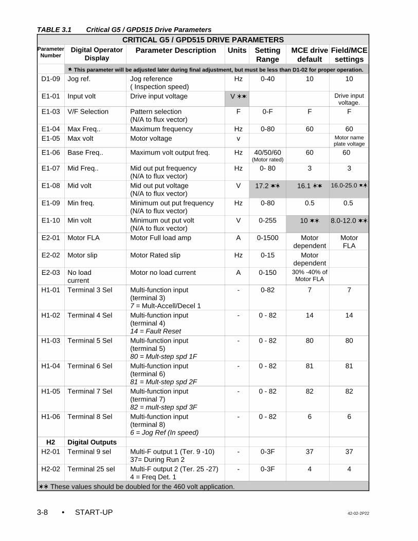
TABLE 3.1 Critical G5 / GPD515 Drive Parameters
CRITICAL G5 / GPD515 DRIVE PARAMETERSParameterNumber
Digital OperatorDisplay
Parameter Description Units SettingRange
MCE drivedefault
Field/MCEsettings
• START-UP 42-02-2P223-8
w This parameter will be adjusted later during final adjustment, but must be less than D1-02 for proper operation.
D1-09 Jog ref. Jog reference( Inspection speed)
Hz 0-40 10 10
E1-01 Input volt Drive input voltage V ww Drive inputvoltage.
E1-03 V/F Selection Pattern selection(N/A to flux vector)
F 0-F F F
E1-04 Max Freq.. Maximum frequency Hz 0-80 60 60E1-05 Max volt Motor voltage v Motor name
plate voltage
E1-06 Base Freq.. Maximum volt output freq. Hz 40/50/60(Motor rated)
60 60
E1-07 Mid Freq.. Mid out put frequency(N/A to flux vector)
Hz 0- 80 3 3
E1-08 Mid volt Mid out put voltage(N/A to flux vector)
V 17.2 ww 16.1 ww 16.0-25.0 ww
E1-09 Min freq. Minimum out put frequency(N/A to flux vector)
Hz 0-80 0.5 0.5
E1-10 Min volt Minimum out put volt(N/A to flux vector)
V 0-255 10 ww 8.0-12.0 ww
E2-01 Motor FLA Motor Full load amp A 0-1500 Motordependent
MotorFLA
E2-02 Motor slip Motor Rated slip Hz 0-15 Motordependent
E2-03 No load current
Motor no load current A 0-150 30% -40% ofMotor FLA
H1-01 Terminal 3 Sel Multi-function input (terminal 3)7 = Mult-Accell/Decel 1
- 0-82 7 7
H1-02 Terminal 4 Sel Multi-function input (terminal 4) 14 = Fault Reset
- 0 - 82 14 14
H1-03 Terminal 5 Sel Multi-function input (terminal 5) 80 = Mult-step spd 1F
- 0 - 82 80 80
H1-04 Terminal 6 Sel Multi-function input (terminal 6)81 = Mult-step spd 2F
- 0 - 82 81 81
H1-05 Terminal 7 Sel Multi-function input (terminal 7) 82 = mult-step spd 3F
- 0 - 82 82 82
H1-06 Terminal 8 Sel Multi-function input (terminal 8)6 = Jog Ref (In speed)
- 0 - 82 6 6
H2 Digital OutputsH2-01 Terminal 9 sel Multi-F output 1 (Ter. 9 -10)
37= During Run 2- 0-3F 37 37
H2-02 Terminal 25 sel Multi-F output 2 (Ter. 25 -27)4 = Freq Det. 1
- 0-3F 4 4
ww These values should be doubled for the 460 volt application.

42-02-2P22 START-UP • 3-9
TABLE 3.2 Additional G5 / GPD515 Drive Parameters Applicable to Flux Vector Applications
ADDITIONAL G5 / GPD515 DRIVE PARAMETERS APPLICABLE TO FLUX VECTOR
ParameterNumber
Digital OperatorDisplay
Parameter Description Units SettingRange
MCEdrive
default
Field/MCE
settings
C5 ASR TUNING
C5-01 ASR P Gain1 ASR proportional gain 1 - 0.0-300 20.0 20.0
C5-02 ASR I Time 1 ASR integral time 1 s 0.00- 10.0 0.50 0.20
C5-03 ASR P Gain 2 ASR proportional gain 2 - 0.00-300.0 20.0 20.0
C5-04 ASR I Time 2 ASR integral time 2 s 0.0- 10.0 0.50 0.50
F1 PG Option Setup
F1-01 PG pulse/Rev PG constant - 0-60000 1024 1024
F1-02 PG Fdbk Loss sel Stopping method at PG line brakedetection.0: Ramp to stop 2:Fast Stop1: Cost to stop 3: Alarm only
- 0-3 1 1
F1-03 PG overspeed sel Stopping method at OS detection.0: Ramp to stop 2:Fast Stop1: Cost to stop 3: Alarm only
- 0-3 1 1
F1-04 PG Deviation sel Stopping method at DEVdetection.0: Ramp to stop 2:Fast Stop1: Cost to stop 3: Alarm only
- 0-3 1 1
F1-05 PG Rotation sel PG rotation0: CCW 1: CW
- 0/1 0 0 or 1
F1-06 PG output ratio PG division rate - 1-132 1 1
F1-07 -F1-13
Set at drive defaults.
L4 Ref detection
L4-01 Spd Agree Level Speed agree det level (L4-01 = E1-06)
Hz 0-400 60 60
L4-02 Spd Agree width Speed agree det width Hz 0-20 5 5.0-8.0
L7-01 -L704
Torque limits Set at Factory defaults - 0-300 300 300
• START-UP 42-02-2P223-10
WARNING: The motor circuit may have high voltage present whenever AC poweris applied to the controller, even when the motor is not rotating. Donot open the drive cover for 5-10 minutes after removing the ACpower, to allow the capacitors to discharge. Use extreme caution. Donot touch any circuit board, power device or electrical connectionwithout insuring that high voltage is not present.
3.4.3 MOVING THE CAR ON INSPECTION OPERATION (G5 / GPD515)
Once all the steps described in Sections 3.3.1, 3.4.1 and 3.4.2 are accomplished then proceedwith the following.
a. Verify that the MACHINE ROOM INSPECTION TRANSFER switch on the SC-SB2Kboard is in the INSP position. Turn ON the main power disconnect. After a few secondsthe SAFR1 and SAFR2 relays should pick (the LED near the relay will be lit). On theHC-ACI board relays RDY and CNP must also be picked. If none of the relays havepicked, inspect fuse F4 on the controller’s back plate. Verify that there is 120 VACbetween test pins TP1 and TP2 on the SC-SB2K Main Safety Relay board.
If no problems are found, then briefly place a jumper between panel mount terminal 2and PCB terminal 20 on the SC-SB2K board and confirm that the SAFR1 & SAFR2relays turn ON after four seconds. If the SAFR relays turn OFF after removing thejumper, there is a problem with the safety string. Note that the RDY relay will turn ONas long as the VFAC drive is in normal condition and there is +/-15DVC present on theHC-ACI board. The N.C. contact of the fault tripping output on the drive is used to pickthe RDY relay. This contact opens if there is a fault in the VFAC drive unit. The fault canbe reset by pressing the drive reset button on the HC-ACI board or by pressing thedrive reset button on the drive keypad.
b. All of the speed commands (acceleration, deceleration and the S curves) are adjusted
by setting drive parameters using the drive key pad. A complete listing of theG5/GPD515 Drive Parameters is found in Appendix B. A parameter sheet, listing theparameter settings as shipped from MCE, is shipped with each controller.
c. If required, install a temporary jumper between terminals 2 and 9 to bypass the doorlocks. If the car is on a final limit switch, place a jumper between terminals 2 and 16 tobypass the main safety string. Remember to remove these jumpers as soon aspossible.
d. For Flux Vector applications, the encoder must be mounted on the motor shaft and itsconnections must be complete according to the job prints at this time.
e. The inspection speed is set by drive parameter D1-09 in Hz. For flux vectorapplications, set D1-09 = 4Hz as the initial setting to slowly move the car & toprevent arcing on the contactors during initial start up. Verify that the MACHINEROOM INSPECTION TRANSFER switch on the SC-SB2K board is in the INSPposition. Verify that the drive is in OPERATION mode. Run the car in the desireddirection by toggling the UP/DN toggle switch on the SC-SB2K board. The PMcontactor and the BK contactor should pick and the car should move. Make sure thatthe car moves in the appropriate direction and the brake works properly.

42-02-2P22 START-UP • 3-11
NOTE: If the elevator does not run on Inspection, refer to Section 6.5,Troubleshooting the G5 / GPD515 AC Drive.
If the car moves in the opposite direction:
• for open loop applications, interchange two of the motor leads.
• for flux vector applications, display the OUTPUT CURRENT on the drive keypadby pressing the UP arrow (twice). Pick direction on Inspection and check thefollowing:
1. If the car moves in the opposite direction and draws a normal value ofcurrent(less than the Motor FLA or approximately 30% to 40% of motorFLA), then perform the following steps:
(a) Turn the controller power OFF. Interchange two of the motorconnections.
(b) Turn the controller power ON. Set parameter F1-05 = CCW if itsoriginal setting is CW. If the original setting was CCW then set F1-05to CW. The car should now move in the correct direction and draw thenormal value of current.
2. If the car moves in the opposite direction and draws higher current thannormal:
(a) Turn the controller power OFF. Interchange two of the motor leads.
(b) Turn the controller power ON and check the direction and current. Ifthe car moves in correct direction but still draws higher than normalcurrent, go to step 3.
3. If the car moves in the correct direction and draws higher current thanthe Motor FLA and the value of current keeps increasing, stop the car andset parameter F1-05 = CCW if its original setting is CW. If the originalsetting is CCW then set F1-05 to CW. The car should now move in thecorrect direction and draw the normal value of current.
f. The inspection speed in Hz should show on the drive key pad whenever the car movesat inspection speed. Adjust drive parameter D1-09 for a comfortable inspection speed.For proper brake operation, adjust the SPD trimpot on the HC-ACI board to coordinatethe application of the speed command with the picking of the brake so that the car doesnot move under the brake or rollback at the start.
g. At this time the adjustment of the BDD trimpot on the HC-ACI board is also necessary.Otherwise the car may be stopping under the brake, causing a lot of current to beapplied to the motor that might cause arcing on the main contactor during the stop. OnInspection operation, how quickly the car stops at the terminal landings is controlled bydrive parameter C1-04. A higher value of this parameter will cause the car to overshootat terminal landings and may drop the SAFR1 relay. Also, on Inspection operation thesmoothness in the stop at intermediate landings is controlled by the normal decelerationparameter C1-02.
h. Test the safety by hand to make sure that it will hold the car.
• START-UP 42-02-2P223-12
NOTE: If the car is not completely wired (temporary), check the following:• wire removed from panel mount terminal DCL• 2-bus jumped to terminal DPM • wire removed from terminal 47 on the SC-SB2K board• jumper from 2 bus to terminal 36 on the SC-SB2K board• jumper from 2 bus to terminal 38 on the SC-SB2K board• jumper from 2 bus to panel mount terminal EPI (if present)
NOTE: On modernizations it is easy to overlook the typical 40% counter-weighting.Always put a 40% load in the car and check for equal motor current (upverses down) at Inspection speed in the middle of the hoistway. Equalcurrent readings on the keypad display indicate that the counterweight isclose to the correct value. Take whatever steps are necessary to achieveproper counterweighting. This is especially important since many tractioninstallations do not have compensation cables or chains.
i. To make sure that the Car Top Inspection switch is working properly, turn OFF the maindisconnect, remove the jumper between terminals 18 and ACCN, from step 3.3.1 (j),and reinstall the wire into terminal ACCN. Turn ON the main disconnect. Make sure thatthere is 115VAC on terminal ACCN with respect to terminal 1 when the car topinspection switch is in the NORMAL position. There should be no power on terminalACCN when the car top inspection switch is in the INSP position.
j. Stop the car so that the car top is accessible from the top hall door. Remove jumpersfrom the safety circuit. Run the car from the car top Inspection station. Verify thatthe SAFR1 relay drops out and the car stops when the Car Top Emergency StopSwitch is released. Also, by opening the Emergency Stop Switch while the car ismoving up or down, verify that the brake stops and holds the car.
k. Run the car through the hoist way, checking clearance and the door locks. When all ofthe doors are closed, remove the jumpers from terminals 2 and 9, and fromterminals 18 and ACCN (if present). Correct any problem with the door locks and thedoor closed contacts.
l. Temporarily take the car off of Inspection operation. If the LED display does not showTEST MODE, see what message is being displayed and correct the problem. Forexample, if the indicators show that the car is on Fire Service Phase 1, a jumper mustbe connected between terminal 2 on the back plate and terminal 38 on the SC-SB2Kboard in order to run the car on Normal Operation. Remove the jumper once the FireService input is brought into the controller. Place the car back on Inspection.
m. Check the counter weight balance. Make whatever corrections are necessary to makethe counter weight correct. Check to see what the counter weighing should be beforemaking any changes. If a drum machine is being used, follow the manufacturer’scounterweighting recommendation, and test the drum machine’s limit switches.
n. Turn OFF the power and reinstall the fuses that power terminals 2H and 2F. Thecontroller installation should now be complete. Proceed to Section 4 Final Adjustment.
42-02-2P22 START-UP • 3-13
NOTE: The drive software has been modified for this application, therefore someof the parameters on the parameter sheet shipped with the controller aredifferent from those shown in the drive manual. If a drive is replaced in thefield, all of the drive parameters should be entered manually and should beverified according to the parameter sheet shipped with the controller.
3.5 INSPECTION OPERATION - MAGNETEK HPV 900 DRIVEFor controllers with the G5 / GPD515 drive, see Section 3.4.For controllers with the TORQMAX F4 drive, see Section 3.6.For controllers with the Yaskawa F7 drive, see Section 3.7.For controllers with the TORQMAX F5 drive, see Section 3.8.
3.5.1 DRIVE PARAMETER SETTINGS
Each controller is shipped with completed parameter sheets, and all of the field adjustableparameters have been entered into the drive unit based upon the provided field information.However, it is essential to verify all drive parameter settings before start up.
Refer to the instruction manual for the VFAC drive unit which is provided along with this manualas part of the documentation. Become familiar with the VFAC Drive Manual, particularly withthe operation of the Digital Operator (keypad operation). Note that the way this VFAC drive unitis being used ignores many of its functions. Pages D and DX of the job prints show the driveinterface and which external functions are being used.
3.5.2 VERIFYING THE CRITICAL MAGNETEK HPV 900 DRIVE PARAMETERS
The AC drive parameters must be verified before moving the car on inspection operation. TheCaution box below lists critical drive parameters which must be verified before start up. Theremaining drive parameters must be verified with the Quick Reference for HPV 900 DriveParameters for the Series M product which was shipped with the controller. This completelisting of drive parameters can also be found in Appendix C of this manual.
NOTE: Before the initial inspection run, verify the following trimpot settings:• COS trimpot on the SC-BASE or BASER board fully CW• ETS trimpot on the SC-BASE or BASER board fully CW• ILO trimpot on the SC-BASE or BASER board fully CW• ILO trimpot on the HC-ACI board fully CCW• ETS trimpot on the HC-ACIF board fully CW
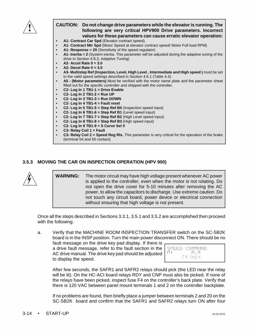
• START-UP 42-02-2P223-14
CAUTION: Do not change drive parameters while the elevator is running. Thefollowing are very critical HPV900 Drive parameters. Incorrectvalues for these parameters can cause erratic elevator operation:
• A1- Contract Car Spd (Elevator contract speed).• A1- Contract Mtr Spd (Motor Speed at elevator contract speed/ Motor Full load RPM)• A1- Response = 20 (Sensitivity of the speed regulator) • A1- Inertia = 2 (System inertia. This parameter will be adjusted during the adaptive tuning of the
drive in Section 4.8.3, Adaptive Tuning) • A2- Accel Rate 0 = 3.0 • A2- Decel Rate 0 = 3.0 • A3- Multistep Ref (Inspection, Level, High Level , Intermediate and High speed ) must be set
to the valid speed settings described in Section 4.6.1 (Table 4.4).• A5 - (Motor parameters) Must be verified with the motor name plate and the parameter sheet
filled out for the specific controller and shipped with the controller.• C2- Log In 1 TB1-1 = Drive Enable• C2- Log In 2 TB1-2 = Run UP• C2- Log In 3 TB1-3 = Run DOWN• C2- Log In 4 TB1-4 = Fault reset• C2- Log In 5 TB1-5 = Step Ref B0 (Inspection speed input)• C2- Log In 6 TB1-6 = Step Ref B1 (Level speed input) • C2- Log In 7 TB1-7 = Step Ref B2 (High Level speed input)• C2- Log In 8 TB1-8 = Step Ref B3 (High speed input)• C2- Log In 9 TB1-9 = S Curve Sel 0• C3- Relay Coil 1 = Fault• C3- Relay Coil 2 = Speed Reg Rls. This parameter is very critical for the operation of the brake
(terminal 54 and 55 contact)
WARNING: The motor circuit may have high voltage present whenever AC poweris applied to the controller, even when the motor is not rotating. Donot open the drive cover for 5-10 minutes after removing the ACpower, to allow the capacitors to discharge. Use extreme caution. Donot touch any circuit board, power device or electrical connectionwithout ensuring that high voltage is not present.
SPEED COMMAND
D1 0.0
ft/min
3.5.3 MOVING THE CAR ON INSPECTION OPERATION (HPV 900)
Once all the steps described in Sections 3.3.1, 3.5.1 and 3.5.2 are accomplished then proceedwith the following.
a. Verify that the MACHINE ROOM INSPECTION TRANSFER switch on the SC-SB2K
board is in the INSP position. Turn the main power disconnect ON. There should be nofault message on the drive key pad display. If there isa drive fault message, refer to the fault section in theAC drive manual. The drive key pad should be adjustedto display the speed.
After few seconds, the SAFR1 and SAFR2 relays should pick (the LED near the relaywill be lit). On the HC-ACI board relays RDY and CNP must also be picked. If none ofthe relays have been picked, inspect fuse F4 on the controller’s back plate. Verify thatthere is 120 VAC between panel mount terminals 1 and 2 on the controller backplate.
If no problems are found, then briefly place a jumper between terminals 2 and 20 on theSC-SB2K board and confirm that the SAFR1 and SAFR2 relays turn ON after four
42-02-2P22 START-UP • 3-15
NOTE: If the elevator does not run on Inspection, refer to Section 6.6,Troubleshooting the MagneTek HPV 900 AC Drive.
seconds. If the SAFR relays turn OFF after removing the jumper, there is a problemwith the safety string. Note that the RDY relay will turn ON as long as the VFAC driveis in normal condition and there is +/-15DVC present on the HC-ACI board. The N.C.contact of the fault tripping output on the drive is used to pick the RDY relay. Thiscontact opens if there is a fault in the VFAC drive unit. The fault can be reset bypressing the drive reset button on the HC-ACI board or by pressing the drive resetbutton on the drive keypad.
b. All of the speed commands (acceleration, deceleration and the S curves) are adjusted
by setting drive parameters using the drive key pad. A complete listing of the HPV 900Drive Parameters is found in Appendix C. A parameter sheet, listing the parametersettings as programmed by MCE, is shipped with each controller.
c. If required, install a temporary jumper between terminals 2 and 9 to bypass the doorlocks. If the car is on a final limit switch, place a jumper between terminals 2 and 16 tobypass the main safety string. Remember to remove these jumpers as soon aspossible.
d. At this time the encoder must be mounted on the motor shaft and its connections mustbe complete according to the job prints.
e. The Inspection Speed is set by the A3 - Inspection / Speed Command 1, parameterin ft/min. Verify that the MACHINE ROOM INSPECTION TRANSFER switch on the SC-SB2K board is in the INSP position. Run the car by toggling the UP/DN toggle switchon the SC-SB2K board in the desired direction using constant pressure. The PMcontactor and the BK contactor should pick and the car should move. Make sure thatthe car moves in the appropriate direction and the brake works properly.
If the car moves in the opposite direction, display the MOTOR CURRENT on thedrive keypad under DISPLAY POWER DATA D2. Pick direction on Inspection andcheck for one of the following conditions:
1. If the car moves in the correct direction and the drive draws normal current (30%to 40% of motor FLA) proceed to step f.
2. If the car oscillates at zero speed, moves at slow speed, or a Torque Limit DriveFault is tripped, interchange two of the motor leads to correct this problem.
3. If the motor draws normal current but the car moves in the opposite direction,change the C1- Motor Rotation parameter from Forward to Reverse, or viceversa.
f. Verify the inspection speed using a hand held Tachometer. If the car moves slower thanthe set value of A3 - Inspection/Speed Command 1 then increase the A1 - ContractMtr Spd rpm parameter. If the speed is higher, decrease the value of the A1-ContractMtr Spd rpm parameter. The A1- Contract Mtr Spd parameter can be adjusted up to+/-5% of the motor rated F.L. RPM without having much effect on the performance.
The correct Inspection speed in feet per minute (ft/m) should now be displayed on thedrive key pad whenever the car moves on Inspection. Adjust the Inspection Speed
• START-UP 42-02-2P223-16
NOTE: If the car is not completely wired (temporary), check the following:• wire removed from panel mount terminal DCL• jumper between 2-bus and panel mount terminal DPM• wire removed from terminal 47 on the SC-SB2K board• jumper from 2 bus to terminal 36 on the SC-SB2K board• jumper from 2 bus to terminal 38 on the SC-SB2K board• jumper from 2 bus to panel mount terminal EPI (if present)
(A3 - Inspection/Speed Command 1) parameter for a comfortable inspection speed.For proper brake operation, adjust the SPD trimpot on the HC-ACI board to coordinatethe application of the speed command with the picking of the brake so that the car doesnot move under the brake or rollback at the start.
g. At this time the adjustment of the BDD trimpot on the HC-ACI board is also necessary.Otherwise the car may be stopping under the brake, causing a lot of current to beapplied to the motor that might cause arcing on the main contactor during the stop.
h. Test the safety by hand to make sure that it will hold the car.
i. To make sure that the Car Top Inspection switch is working properly, turn OFF the maindisconnect, remove the jumper between terminals 18 and ACCN, from step 3.3.1 (j),and reinstall the wire into terminal ACCN. Turn ON. the main disconnect. Make surethat there is 115VAC on terminal ACCN with respect to terminal 1 when the car topinspection switch is in the NORMAL position. There should be no power on terminalACCN when the car top inspection switch is in the INSP position.
j. Stop the car so that the car top is accessible from the top hall door. Remove jumpersfrom the safety circuit. Run the car from the car top Inspection station. Verify thatthe SAFR1 relay drops out and the car stops when the Car Top Emergency StopSwitch is released. Also, by opening the Emergency Stop Switch while the car ismoving up or down, verify that the brake stops and holds the car.
k. Run the car through the hoist way, checking clearance and the door locks. When all ofthe doors are closed, remove the jumpers from terminals 2 and 9, and fromterminals 18 and ACCN (if present). Correct any problem with the door locks and thedoor closed contacts.
l. Temporarily take the car off of Inspection operation. If the LCD display does not showTEST MODE, see what message is being displayed and correct the problem. Forexample, if the indicators show that the car is on Fire Service Phase 1, a jumper mustbe connected between terminal 2 on the back plate and terminal 38 on the SC-SB2Kboard in order to run the car on Normal Operation. Remove the jumper once the FireService input is brought into the controller. Place the car back on Inspection.
m. Check the counter weight balance. Make whatever corrections are necessary to makethe counter weight correct. Check to see what the counter weighing should be beforemaking any changes. If a drum machine is being used, follow the manufacturer’scounterweighting recommendation, and test the drum machine’s limit switches.
42-02-2P22 START-UP • 3-17
NOTE: On modernizations it is easy to overlook the typical 40% counter-weighting.Always put a 40% load in the car and check for equal motor current (upverses down) at Inspection speed in the middle of the hoistway. Equalcurrent readings on the keypad display indicate that the counterweight isclose to the correct value. Take whatever steps are necessary to achieveproper counterweighting. This is especially important since many tractioninstallations do not have compensation cables or chains.
NOTE: The drive software has been modified for this application, therefore someof the parameters on the parameter sheet shipped with the controller aredifferent from those shown in the drive manual. If a drive is replaced in thefield, all of the drive parameters should be entered manually and should beverified according to the parameter sheet shipped with the controller.
n. Turn OFF the power and reinstall the fuses that power terminals 2H and 2F. Theelevator controller installation should now be complete. Proceed to Section 4 FinalAdjustment.
3.6 INSPECTION OPERATION - TORQMAX F4 DRIVE
For controllers with the G5 / GPD515 drive, see Section 3.4.For controllers with the HPV 900 drive, see Section 3.5.For controllers with the Yaskawa F7 drive, see Section 3.7.For controllers with the TORQMAX F5 drive, see Section 3.8.
3.6.1 TORQMAX F4 DRIVE PARAMETER SETTINGS
Each controller is shipped with completed parameter sheets, and all of the field adjustableparameters have been entered into the drive unit based upon the provided field information.However, it is essential to verify all drive parameter settings before start up.
Refer to the instruction manual for the VFAC drive unit which is provided along with this manualas part of the documentation. Become familiar with the VFAC Drive Manual, particularly withthe operation of the Digital Operator (keypad operation). Note that the way this VFAC drive unitis being used ignores many of its functions. Pages D and DX of the job prints show the driveinterface and which external functions are being used.
3.6.2 VERIFYING THE CRITICAL TORQMAX F4 DRIVE PARAMETERS
The AC drive parameters must be verified before moving the car on inspection operation. TheCaution box below lists critical drive parameters which must be verified before start up. The
NOTE: Before the initial inspection run, verify the following trimpot settings:• COS trimpot on the SC-BASE or BASER board fully CW• ETS trimpot on the SC-BASE or BASER board fully CW• ILO trimpot on the SC-BASE or BASER board fully CW• ILO trimpot on the HC-ACI board fully CCW• ETS trimpot on the HC-ACIF board fully CW
• START-UP 42-02-2P223-18
CAUTION: Do not change drive parameters while the elevator is running. Thefollowing are very critical TORQMAX Drive parameters. Incorrectvalues for these parameters can cause erratic elevator operation:
• LF.02 = 2 (Operating mode)• LF.04 = 0 (Induction motor)• LF.07 = US (Unit selection)• LF.10 Rated motor power (HP).• LF.11 Rated motor speed (RPM). • LF.12 Rated motor current (Amp).• LF.13 Rated motor frequency (Hz).• LF.14 Rated motor voltage.• LF.17 Encoder pulse number (PPR)closed loop• LF.20 Rated speed (FPM)• LF.21 Traction sheave diameter (inches)
• LF.22 Gear Reduction ratio • LF.23 Roping Ratio• LF.24 Load (LBS)• LF.30 ( 2 = Closed loop: 0 = open loop)• LF.31 Speed Prop gain• LF.32 Speed Int gain• LF.42 High Speed (FPM)• LF.43 Inspection speed (FPM)• LF.44 High level speed (FPM)• LF.45 Intermediate speed (FPM)• LF.51 Acceleration ft/s.s• LF.53 Deceleration ft/s.s
WARNING: The motor circuit may have high voltage present whenever AC poweris applied to the controller, even when the motor is not rotating. Donot open the drive cover for 5-10 minutes after removing the ACpower, to allow the capacitors to discharge. Use extreme caution. Donot touch any circuit board, power device or electrical connectionwithout ensuring that high voltage is not present.
remaining drive parameters must be verified with the Quick Reference for TORQMAX DriveParameters for Series M product which was shipped with the controller. This complete listingof drive parameters can also be found in Appendix D of this manual.
3.6.3 MOVING THE CAR ON INSPECTION OPERATION (TORQMAX F4)
Once all the steps described in Sections 3.3.1, 3.6.1 and 3.6.2 are accomplished then proceedwith the following.
a. Verify that the MACHINE ROOM INSPECTION TRANSFER switch on the SC-SB2Kboard is in the INSP position. Turn ON the main power disconnect. Under normalconditions there should be no fault message on the drive key pad display. If there is adrive fault message, refer to the fault section in the AC drive manual. The drive key padshould be adjusted to display the speed.
After a few seconds, the SAFR1 and SAFR2 relays should pick (the LED near the relaywill be lit). On the HC-ACI board, relays RDY and CNP must also be picked. If none ofthe relays have picked, inspect fuse F4 on the controller’s back plate. Verify that thereis 120 VAC between panel mount terminals 1 and 2.
If no problems are found, then briefly place a jumper between panel mount terminal 2and 20 (on the SC-SB2K) and confirm that the SAFR1 and SAFR2 (SAFR relays) relaysturn ON after four seconds. If the SAFR relays turn OFF after removing the jumper,there is a problem with the safety string. Note that the RDY relay will turn ON as longas the VFAC drive is normal and there is +/-15DVC present on the HC-ACI board. TheN.C. contact of the fault tripping output on the drive is used to pick the RDY relay. Thiscontact opens if there is a fault in the VFAC drive unit. The fault can be reset bypressing the drive reset button on the HC-ACI board or by pressing the drive resetbutton on the drive keypad.
42-02-2P22 START-UP • 3-19
NOTE: If the elevator does not run on Inspection, refer to Section 6.7,Troubleshooting the TORQMAX AC Drive.
b. All of the speed commands (acceleration, deceleration and the S curves) are adjustedby setting drive parameters using the drive key pad. A complete listing of theTORQMAX Drive Parameters is found in Appendix D. A parameter sheet, listing theparameter settings as programmed by MCE, is shipped with each controller.
c. If required, install a temporary jumper between terminals 2 and 9 to bypass the doorlocks. If the car is on a final limit switch, place a jumper between terminals 2 and 16 tobypass the main safety string. Remember to remove these jumpers as soon aspossible.
d. For Flux Vector applications, the encoder must be mounted on the motor shaft and itsconnections must be complete according to the job prints at this time.
e. The Inspection Speed is set by drive parameter LF.43. Verify that the MACHINEROOM INSPECTION TRANSFER switch on the SC-SB2K board is in the INSPposition. Run the car by toggling the UP/DN toggle switch on the SC-SB2K board in thedesired direction using constant pressure. The PM and BK contactors should pick andthe car should move.
If the car doesn't move, select drive parameter LF.86. The value of LF.86 changes fromzero (0) to four (4) when direction is picked on Inspection. If the value remains zero (0),the drive is not receiving the Inspection speed command from the controller. Refer toSection 6.7 for troubleshooting information.
f. Verify that the car moves in the appropriate direction and the brake works properly.
• Open loop applications - If the car moves in the opposite direction, interchangetwo of the motor leads.
• Flux vector applications - Display the MOTOR CURRENT on the drive keypadby selecting parameter ru.9. Run the car on Inspection and check for one of thefollowing conditions:
1. If the car moves in the correct direction and the drive draws normal current(30% to 40% of motor FLA) proceed to step g.
2. If the car oscillates at zero speed, moves at slow speed, or trips the E.ENCfault on the drive then set LF.18 = ON or OFF (change from previousvalue). This parameter will swap the encoder channels internally in the drive.It is not recommended to change the external encoder connections as thedrive has the capability of changing them through software.
3. If the motor draws normal current but the car moves in the oppositedirection, turn OFF the power and wait until there is no voltage present onthe DC bus. Then interchange two of the motor leads.
Turn ON the power and set parameter LF18 = ON or OFF(change fromprevious value). The car should now move in the correct direction and drawnormal current.
• START-UP 42-02-2P223-20
g. Verify the inspection speed using a hand held tachometer. If the car moves slower thanthe set value of the Inspection speed parameter (LF.43) then verify the following:
• LF.11 Rated motor speed.• LF.20 Rated system speed• LF.21 Traction sheave diameter.• LF.22 Gear reduction ratio. • LF.30 (2 = Close loop, 0 = Open loop)
If the gear reduction ratio is not available from the machine name plate, calculate thevalue by first measuring the motor revolutions using a marker on the motor shaft orbrake drum. Reduce the inspection speed by decreasing LF.43, then determine thenumber of motor shaft revolutions required to complete one revolution of the sheave.Calculate the gear reduction ration using the formula: Gear reduction ratio = MotorRPM / Sheave RPM. Enter the calculated value in parameter LF.22.
Note: The drive has the capability of estimating the gear reduction ratio. Run the car oninspection and read the value parameter LF.25, the gear ratio estimated by the drive.The value of LF.25 can be used for LF.22. However, the correct value of LF.22 is criticalfor overall system performance, therefore MCE/TORQMAX recommends calculating ormeasuring the gear reduction ratio and entering the calculated value in parameter LF.22if it is not available from the machine name plate.
Adjust the Inspection Speed for a comfortable inspection speed using parameter LF.43.For proper brake operation, adjust the SPD trimpot on the HC-ACI board to coordinatethe application of the speed command with the picking of the brake so that the car doesnot move under the brake or rollback at the start.
h. At this time the adjustment of the BDD trimpot on the HC-ACI board is also necessary.Otherwise the car may be stopping under the brake, causing a lot of current to beapplied to the motor that might cause arcing on the main contactor during the stop.
i. Test the safety by hand to make sure that it will hold the car.
j. To make sure that the Car Top Inspection switch is working properly, turn OFF the maindisconnect, remove the jumper between terminals 18 and ACCN, from step 3.3.1 (j),and reinstall the wire into terminal ACCN. Turn ON the main disconnect. Make sure thatthere is 115VAC on terminal ACCN with respect to terminal 1 when the car topinspection switch is in the NORMAL position. There should be no power on terminalACCN when the car top inspection switch is in the INSP position.
k. Stop the car so that the car top is accessible from the top hall door. Remove jumpersfrom the safety circuit. Run the car from the car top Inspection station. Verify thatthe SAFR1 relay drops out and the car stops when the Car Top Emergency StopSwitch is released. Also, by opening the Emergency Stop Switch while the car ismoving up or down, verify that the brake stops and holds the car.
l. Run the car through the hoist way, checking clearance and the door locks. When all ofthe doors are closed, remove the jumpers from terminals 2 and 9, and fromterminals 18 and ACCN (if present). Correct any problem with the door locks and thedoor closed contacts.
42-02-2P22 START-UP • 3-21
NOTE: If the car is not completely wired (temporary), check the following:• wire removed from panel mount terminal DCL• jumper placed between 2-bus and panel mount terminal DPM• wire removed from terminal 47 on the SC-SB2K board• jumper from 2 bus to terminal 36 on the SC-SB2K board• jumper from 2 bus to terminal 38 on the SC-SB2K board• jumper from 2 bus to panel mount terminal EPI (if present)
NOTE: On modernizations it is easy to overlook the typical 40% counter-weighting.Always put a 40% load in the car and check for equal motor current (upverses down) at Inspection speed in the middle of the hoistway. Equalcurrent readings on the keypad display indicate that the counterweight isclose to the correct value. Take whatever steps are necessary to achieveproper counterweighting. This is especially important since many tractioninstallations do not have compensation cables or chains.
m. Temporarily take the car off of Inspection operation. If the LCD display does not showTEST MODE, see what message is being displayed and correct the problem. Forexample, if the indicators show that the car is on Fire Service Phase 1, a jumper mustbe connected between terminal 2 on the back plate and terminal 38 on the SC-SB2Kboard in order to run the car on Normal Operation. Remove the jumper once the FireService input is brought into the controller. Place the car back on Inspection.
n. Check the counter weight balance. Make whatever corrections are necessary to makethe counter weight correct. Check to see what the counter weighing should be beforemaking any changes. If a drum machine is being used, follow the manufacturer’scounterweighting recommendation, and test the drum machine’s limit switches.
o. Turn OFF the power and reinstall the fuses that power terminals 2H and 2F. Theelevator controller installation should now be complete. Proceed to Section 4 FinalAdjustment.
• START-UP 42-02-2P223-22
NOTE: The drive software has been modified for this application, therefore someof the parameters on the parameter sheet shipped with the controller aredifferent from those shown in the drive manual. If a drive is replaced in thefield, all of the drive parameters should be entered manually and should beverified according to the parameter sheet shipped with the controller.
3.7 INSPECTION OPERATION - YASKAWA F7 DRIVE
For controllers with the G5 / GPD515 drive, see Section 3.4.For controllers with the MagneTek HPV 900 drive, see Section 3.5.For controllers with the TORQMAX F4 drive, see Section 3.6.For controllers with the TORQMAX F5 drive, see Section 3.8.
3.7.1 DRIVE PARAMETER SETTINGS
Each controller is shipped with completed parameter sheets, and all of the field adjustableparameters have been entered into the drive unit based upon the provided field information.However, it is essential to verify all drive parameter settings before start up.
Refer to the instruction manual for the VFAC drive unit which is provided along with this manualas part of the documentation. Become familiar with the VFAC Drive Manual, particularly withthe operation of the Digital Operator (keypad operation). Note that the way this VFAC drive unitis being used ignores many of its functions. Pages D and DX of the job prints show the driveinterface and which external functions are being used.
3.7.2 VERIFYING THE CRITICAL YASKAWA F7 DRIVE PARAMETERS
Table 3.1 lists the critical Yaskawa F7 drive parameters which must be verified before start up.Table 3.2 lists additional parameters applicable only to flux vector drives, which must beverified. A complete listing of drive parameters can be found in Appendix J.
NOTE: Before the initial inspection run, verify the following trimpot settings:• COS trimpot on the SC-BASE or BASER board fully CW• ETS trimpot on the SC-BASE or BASER board fully CW• ILO trimpot on the SC-BASE or BASER board fully CW• ILO trimpot on the HC-ACI board fully CCW• ETS trimpot on the HC-ACIF board fully CW
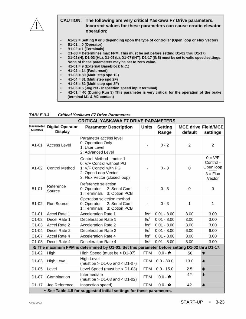
42-02-2P22 START-UP • 3-23
CAUTION: The following are very critical Yaskawa F7 Drive parameters.Incorrect values for these parameters can cause erratic elevatoroperation:
• A1-02 = Setting 0 or 3 depending upon the type of controller (Open loop or Flux Vector)• B1-01 = 0 (Operator)• B1-02 = 1 (Terminals)• O1-03 = Determines max FPM. This must be set before setting D1-02 thru D1-17)• D1-02 (H), D1-03 (HL), D1-05 (L), D1-07 (INT), D1-17 (INS) must be set to valid speed settings.
None of these parameters may be set to zero value.• H1-01 = 9 (External BaseBlock N.C.)• H1-02 = 14 (Fault reset)• H1-03 = 80 (Multi step spd 1F)• H1-04 = 81 (Muti step spd 2F)• H1-05 = 82 (Multi step spd 3F)• H1-06 = 6 (Jog ref - Inspection speed input terminal)• H2-01 = 40 (During Run 3) This parameter is very critical for the operation of the brake
(terminal M1 & M2 contact)
TABLE 3.3 Critical Yaskawa F7 Drive Parameters
CRITICAL YASKAWA F7 DRIVE PARAMETERSParameterNumber
Digital OperatorDisplay
Parameter Description Units SettingRange
MCE drivedefault
Field/MCEsettings
A1-01 Access Level
Parameter access level0: Operation Only1: User Level 2: Advanced Level
- 0 - 2 2 2
A1-02 Control Method
Control Method - motor 10: V/F Control without PG1: V/F Control with PG2: Open Loop Vector3: Flux Vector (closed loop)
- 0 - 3 0
0 = V/FControl -
Open loop---------------
3 = FluxVector
B1-01ReferenceSource
Reference selection0: Operator 2: Serial Com1: Terminals 3: Option PCB
- 0 - 3 0 0
B1-02 Run SourceOperation selection method0: Operator 2: Serial Com1: Terminals 3: Option PCB
- 0 - 3 1 1
C1-01 Accel Rate 1 Acceleration Rate 1 f/s2 0.01 - 8.00 3.00 3.00C1-02 Decel Rate 1 Deceleration Rate 1 f/s2 0.01 - 8.00 3.00 3.00C1-03 Accel Rate 2 Acceleration Rate 2 f/s2 0.01 - 8.00 3.00 3.00C1-04 Decel Rate 2 Deceleration Rate 2 f/s2 0.01 - 8.00 6.00 6.00C1-07 Accel Rate 4 Acceleration Rate 4 f/s2 0.01 - 8.00 3.00 3.00C1-08 Decel Rate 4 Deceleration Rate 4 f/s2 0.01 - 8.00 3.00 3.00 The maximum FPM is determined by O1-03. Set this parameter before setting D1-02 thru D1-17.
D1-02 High High Speed (must be > D1-07) FPM 0.0 - 50 w
D1-03 High Level High Level (must be > D1-05 and < D1-07)
FPM 0.0 - 30.0 13.0 w
D1-05 Level Level Speed (must be < D1-03) FPM 0.0 - 15.0 2.5 w
D1-07 Combination Intermediate (must be > D1-03 and < D1-02)
FPM 0.0 - 42 w
D1-17 Jog Reference Inspection speed) FPM 0.0 - 42 ww See Table 4.8 for suggested initial settings for these parameters.
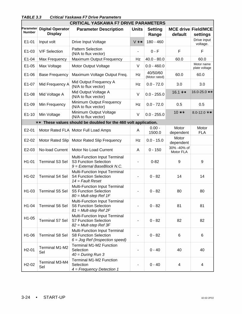
TABLE 3.3 Critical Yaskawa F7 Drive Parameters
CRITICAL YASKAWA F7 DRIVE PARAMETERSParameterNumber
Digital OperatorDisplay
Parameter Description Units SettingRange
MCE drivedefault
Field/MCEsettings
• START-UP 42-02-2P223-24
E1-01 Input volt Drive Input Voltage V ww 180 - 460 Drive inputvoltage.
E1-03 V/F Selection Pattern Selection(N/A to flux vector)
- 0 - F F F
E1-04 Max Frequency Maximum Output Frequency Hz 40.0 - 80.0 60.0 60.0
E1-05 Max Voltage Motor Output Voltage V 0.0 - 460.0 Motor nameplate voltage
E1-06 Base Frequency Maximum Voltage Output Freq. Hz 40/50/60(Motor rated)
60.0 60.0
E1-07 Mid Frequency A Mid Output Frequency A(N/A to flux vector)
Hz 0.0 - 72.0 3.0 3.0
E1-08 Mid Voltage A Mid Output Voltage A(N/A to flux vector)
V 0.0 - 255.0 16.1 ww 16.0-25.0 ww
E1-09 Min Frequency Minimum Output Frequency(N/A to flux vector)
Hz 0.0 - 72.0 0.5 0.5
E1-10 Min Voltage Minimum Output Voltage(N/A to flux vector)
V 0.0 - 255.0 10 ww 8.0-12.0 ww
ww These values should be doubled for the 460 volt application.
E2-01 Motor Rated FLA Motor Full Load Amps A 0.00 -1500.0
Motordependent
MotorFLA
E2-02 Motor Rated Slip Motor Rated Slip Frequency Hz 0.0 - 15.0 Motordependent
E2-03 No-load Current Motor No Load Current A 0 - 150 30% -40% ofMotor FLA
H1-01 Terminal S3 SelMulti-Function Input TerminalS3 Function Selection9 = External BaseBlock N.C.
- 0-82 9 9
H1-02 Terminal S4 SelMulti-Function Input TerminalS4 Function Selection14 = Fault Reset
- 0 - 82 14 14
H1-03 Terminal S5 SelMulti-Function Input TerminalS5 Function Selection80 = Mult-step Ref 1F
- 0 - 82 80 80
H1-04 Terminal S6 SelMulti-Function Input TerminalS6 Function Selection81 = Mult-step Ref 2F
- 0 - 82 81 81
H1-05Terminal S7 Sel
Multi-Function Input TerminalS7 Function Selection82 = Mult-step Ref 3F
- 0 - 82 82 82
H1-06 Terminal S8 SelMulti-Function Input TerminalS8 Function Selection6 = Jog Ref (Inspection speed)
- 0 - 82 6 6
H2-01Terminal M1-M2Sel
Terminal M1-M2 FunctionSelection40 = During Run 3
- 0 - 40 40 40
H2-02Terminal M3-M4Sel
Terminal M1-M2 FunctionSelection4 = Frequency Detection 1
- 0 - 40 4 4
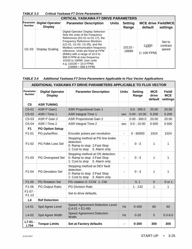
TABLE 3.3 Critical Yaskawa F7 Drive Parameters
CRITICAL YASKAWA F7 DRIVE PARAMETERSParameterNumber
Digital OperatorDisplay
Parameter Description Units SettingRange
MCE drivedefault
Field/MCEsettings
42-02-2P22 START-UP • 3-25
O1-03 Display Scaling
Digital Operator Display SelectionSets the units of the FrequencyReferences (D1-01 to D1-17), theFrequency Reference Monitors(U1-01, U1-02, U1-05), and theModbus communication frequencyreference. Units are fixed at FPM(ft/Min) with a range of 10.0 to999.9 FPM at max frequency. 10100 to 19999: User unitse.g. (10100 = 10.0 FPM) (19999 = 999.9 FPM)
-10110 -19999
11000
(= 100 FPM)
Set tocontractspeed
TABLE 3.4 Additional Yaskawa F7 Drive Parameters Applicable to Flux Vector Applications
ADDITIONAL YASKAWA F7 DRIVE PARAMETERS APPLICABLE TO FLUX VECTOR
ParameterNumber
Digital OperatorDisplay
Parameter Description Units SettingRange
MCEdrive
default
Field/MCE
settings
C5 ASR TUNING
C5-01 ASR P Gain1 ASR Proportional Gain 1 - 0.0 - 300.0 20.00 20.00
C5-02 ASR I Time 1 ASR Integral Time 1 sec 0.00 - 10.00 0.200 0.200
C5-03 ASR P Gain 2 ASR Proportional Gain 2 - 0.00 - 300.0 20.00 20.00
C5-04 ASR I Time 2 ASR Integral Time 2 sec 0.0 - 10.00 0.500 0.500
F1 PG Option Setup
F1-01 PG pulse/Rev Encoder pulses per revolution - 0 - 60000 1024 1024
F1-02 PG Fdbk Loss Sel
Stopping method at PG line brakedetection.0: Ramp to stop 2:Fast Stop1: Cost to stop 3: Alarm only
- 0 - 3 1 1
F1-03 PG Overspeed SelStopping method at OS detection.0: Ramp to stop 2:Fast Stop1: Cost to stop 3: Alarm only
- 0 - 3 1 1
F1-04 PG Deviation Sel
Stopping method at DEV faultdetection.0: Ramp to stop 2:Fast Stop1: Cost to stop 3: Alarm only
- 0 - 3 1 1
F1-05 PG Rotation Sel PG rotation 0: CCW 1: CW - 0, 1 0 0 or 1
F1-06 PG Output Ratio PG Division Rate - 1 - 132 1 1
F1-07 -F1-13
Set to drive defaults.
L4 Ref Detection
L4-01 Spd Agree Level Speed Agreement Detection Level (L4-01 = E1-06)
Hz 0-400 60 60
L4-02 Spd Agree Width Speed Agreement DetectionWidth
Hz 0-20 5 5.0-8.0
L7-01 -L704
Torque Limits Set at Factory defaults - 0-300 300 300
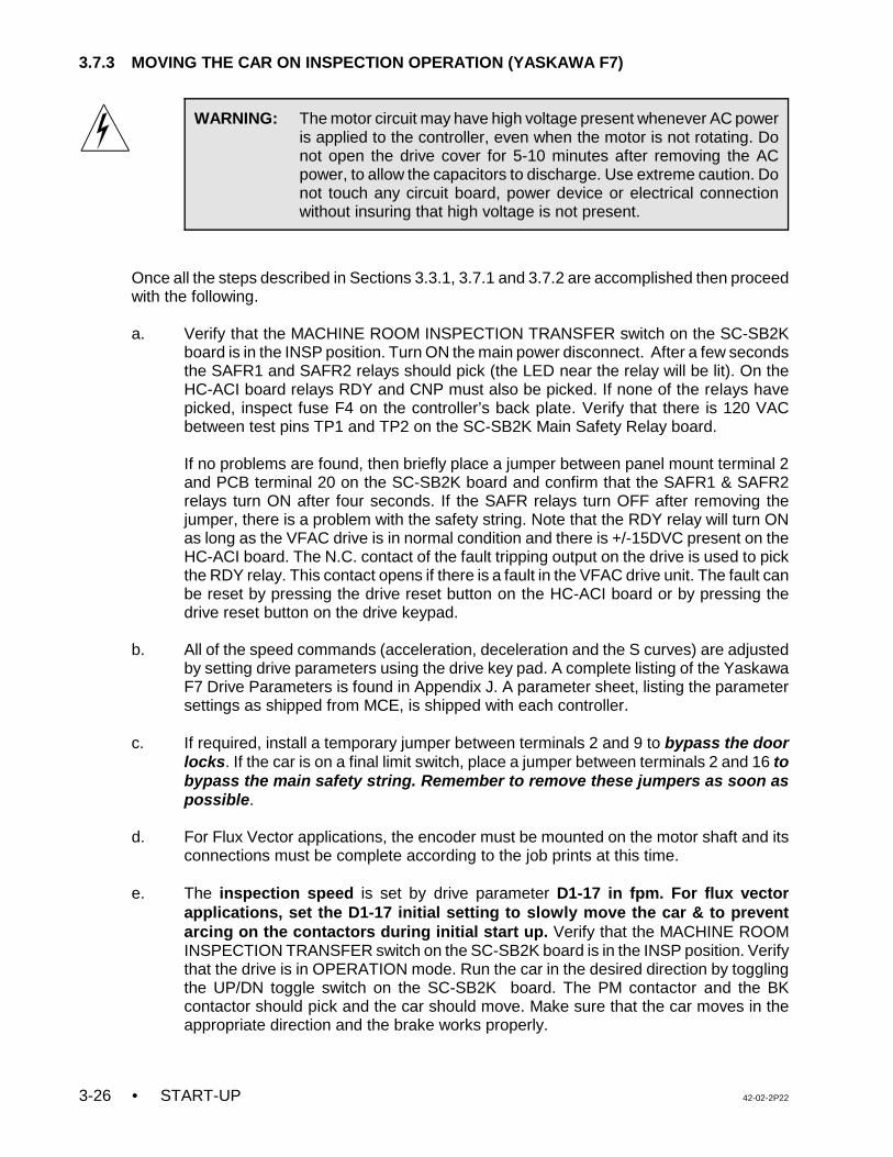
• START-UP 42-02-2P223-26
WARNING: The motor circuit may have high voltage present whenever AC poweris applied to the controller, even when the motor is not rotating. Donot open the drive cover for 5-10 minutes after removing the ACpower, to allow the capacitors to discharge. Use extreme caution. Donot touch any circuit board, power device or electrical connectionwithout insuring that high voltage is not present.
3.7.3 MOVING THE CAR ON INSPECTION OPERATION (YASKAWA F7)
Once all the steps described in Sections 3.3.1, 3.7.1 and 3.7.2 are accomplished then proceedwith the following.
a. Verify that the MACHINE ROOM INSPECTION TRANSFER switch on the SC-SB2Kboard is in the INSP position. Turn ON the main power disconnect. After a few secondsthe SAFR1 and SAFR2 relays should pick (the LED near the relay will be lit). On theHC-ACI board relays RDY and CNP must also be picked. If none of the relays havepicked, inspect fuse F4 on the controller’s back plate. Verify that there is 120 VACbetween test pins TP1 and TP2 on the SC-SB2K Main Safety Relay board.
If no problems are found, then briefly place a jumper between panel mount terminal 2and PCB terminal 20 on the SC-SB2K board and confirm that the SAFR1 & SAFR2relays turn ON after four seconds. If the SAFR relays turn OFF after removing thejumper, there is a problem with the safety string. Note that the RDY relay will turn ONas long as the VFAC drive is in normal condition and there is +/-15DVC present on theHC-ACI board. The N.C. contact of the fault tripping output on the drive is used to pickthe RDY relay. This contact opens if there is a fault in the VFAC drive unit. The fault canbe reset by pressing the drive reset button on the HC-ACI board or by pressing thedrive reset button on the drive keypad.
b. All of the speed commands (acceleration, deceleration and the S curves) are adjusted
by setting drive parameters using the drive key pad. A complete listing of the YaskawaF7 Drive Parameters is found in Appendix J. A parameter sheet, listing the parametersettings as shipped from MCE, is shipped with each controller.
c. If required, install a temporary jumper between terminals 2 and 9 to bypass the doorlocks. If the car is on a final limit switch, place a jumper between terminals 2 and 16 tobypass the main safety string. Remember to remove these jumpers as soon aspossible.
d. For Flux Vector applications, the encoder must be mounted on the motor shaft and itsconnections must be complete according to the job prints at this time.
e. The inspection speed is set by drive parameter D1-17 in fpm. For flux vectorapplications, set the D1-17 initial setting to slowly move the car & to preventarcing on the contactors during initial start up. Verify that the MACHINE ROOMINSPECTION TRANSFER switch on the SC-SB2K board is in the INSP position. Verifythat the drive is in OPERATION mode. Run the car in the desired direction by togglingthe UP/DN toggle switch on the SC-SB2K board. The PM contactor and the BKcontactor should pick and the car should move. Make sure that the car moves in theappropriate direction and the brake works properly.
42-02-2P22 START-UP • 3-27
NOTE: If the elevator does not run on Inspection, refer to Section 6.8,Troubleshooting the Yaskawa F7 AC Drive.
If the car moves in the opposite direction:
• for open loop applications, interchange two of the motor leads.
• for flux vector applications, display the OUTPUT CURRENT on the drive keypadby pressing the UP arrow (twice). Pick direction on Inspection and check thefollowing:
1. If the car moves in the opposite direction and draws a normal value ofcurrent(less than the Motor FLA or approximately 30% to 40% of motorFLA), then perform the following steps:
(a) Turn the controller power OFF. Interchange two of the motorconnections.
(b) Turn the controller power ON. Set parameter F1-05 = CCW if itsoriginal setting is CW. If the original setting was CCW then set F1-05to CW. The car should now move in the correct direction and draw thenormal value of current.
2. If the car moves in the opposite direction and draws higher current thannormal:
(a) Turn the controller power OFF. Interchange two of the motor leads.
(b) Turn the controller power ON and check the direction and current. Ifthe car moves in correct direction but still draws higher than normalcurrent, go to step 3.
3. If the car moves in the correct direction and draws higher current thanthe Motor FLA and the value of current keeps increasing, stop the car andset parameter F1-05 = CCW if its original setting is CW. If the originalsetting is CCW then set F1-05 to CW. The car should now move in thecorrect direction and draw the normal value of current.
f. The inspection speed in FPM should show on the drive key pad whenever the carmoves at inspection speed. Adjust drive parameter D1-17 for a comfortable inspectionspeed. For proper brake operation, adjust the SPD trimpot on the HC-ACI board tocoordinate the application of the speed command with the picking of the brake so thatthe car does not move under the brake or rollback at the start.
g. At this time the adjustment of the BDD trimpot on the HC-ACI board is also necessary.Otherwise the car may be stopping under the brake, causing a lot of current to beapplied to the motor that might cause arcing on the main contactor during the stop. OnInspection operation, how quickly the car stops at the terminal landings is controlled bydrive parameter C1-04. A higher value of this parameter will cause the car to overshootat terminal landings and may drop the SAFR1 relay. Also, on Inspection operation thesmoothness in the stop at intermediate landings is controlled by the normal decelerationparameter C1-02.
h. Test the safety by hand to make sure that it will hold the car.

• START-UP 42-02-2P223-28
NOTE: If the car is not completely wired (temporary), check the following:• wire removed from panel mount terminal DCL• 2-bus jumped to terminal DPM • wire removed from terminal 47 on the SC-SB2K board• jumper from 2 bus to terminal 36 on the SC-SB2K board• jumper from 2 bus to terminal 38 on the SC-SB2K board• jumper from 2 bus to panel mount terminal EPI (if present)
NOTE: On modernizations it is easy to overlook the typical 40% counter-weighting.Always put a 40% load in the car and check for equal motor current (upverses down) at Inspection speed in the middle of the hoistway. Equalcurrent readings on the keypad display indicate that the counterweight isclose to the correct value. Take whatever steps are necessary to achieveproper counterweighting. This is especially important since many tractioninstallations do not have compensation cables or chains.
i. To make sure that the Car Top Inspection switch is working properly, turn OFF the maindisconnect, remove the jumper between terminals 18 and ACCN, from step 3.3.1 (j),and reinstall the wire into terminal ACCN. Turn ON the main disconnect. Make sure thatthere is 115VAC on terminal ACCN with respect to terminal 1 when the car topinspection switch is in the NORMAL position. There should be no power on terminalACCN when the car top inspection switch is in the INSP position.
j. Stop the car so that the car top is accessible from the top hall door. Remove jumpersfrom the safety circuit. Run the car from the car top Inspection station. Verify thatthe SAFR1 relay drops out and the car stops when the Car Top Emergency StopSwitch is released. Also, by opening the Emergency Stop Switch while the car ismoving up or down, verify that the brake stops and holds the car.
k. Run the car through the hoist way, checking clearance and the door locks. When all ofthe doors are closed, remove the jumpers from terminals 2 and 9, and fromterminals 18 and ACCN (if present). Correct any problem with the door locks and thedoor closed contacts.
l. Temporarily take the car off of Inspection operation. If the LED display does not showTEST MODE, see what message is being displayed and correct the problem. Forexample, if the indicators show that the car is on Fire Service Phase 1, a jumper mustbe connected between terminal 2 on the back plate and terminal 38 on the SC-SB2Kboard in order to run the car on Normal Operation. Remove the jumper once the FireService input is brought into the controller. Place the car back on Inspection.
m. Check the counter weight balance. Make whatever corrections are necessary to makethe counter weight correct. Check to see what the counter weighing should be beforemaking any changes. If a drum machine is being used, follow the manufacturer’scounterweighting recommendation, and test the drum machine’s limit switches.
n. Turn OFF the power and reinstall the fuses that power terminals 2H and 2F. Thecontroller installation should now be complete. Proceed to Section 4 Final Adjustment.
42-02-2P22 START-UP • 3-29
NOTE: The drive software has been modified for this application, therefore someof the parameters on the parameter sheet shipped with the controller aredifferent from those shown in the drive manual. If a drive is replaced in thefield, all of the drive parameters should be entered manually and should beverified according to the parameter sheet shipped with the controller.
3.8 INSPECTION OPERATION - TORQMAX F5 DRIVE
For controllers with the G5 / GPD515 drive, see Section 3.4.For controllers with the HPV 900 drive, see Section 3.5.For controllers with the TORQMAX F4 drive, see Section 3.6.For controllers with the Yaskawa F7 drive, see Section 3.7.
3.8.1 TORQMAX F5 DRIVE PARAMETER SETTINGS
Each controller is shipped with completed parameter sheets, and all of the field adjustableparameters have been entered into the drive unit based upon the provided field information.However, it is essential to verify all drive parameter settings before start up.
Refer to the instruction manual for the VFAC drive unit which is provided along with this manualas part of the documentation. Become familiar with the VFAC Drive Manual, particularly withthe operation of the Digital Operator (keypad operation). Note that the way this VFAC drive unitis being used ignores many of its functions. Pages D and DX of the job prints show the driveinterface and which external functions are being used.
3.8.2 VERIFYING THE CRITICAL TORQMAX F5 DRIVE PARAMETERS
The AC drive parameters must be verified before moving the car on inspection operation. TheCaution box below lists critical drive parameters which must be verified before start up. Theremaining drive parameters must be verified with the Quick Reference for TORQMAX F5 DriveParameters for Series M product which was shipped with the controller. This complete listingof drive parameters can also be found in Appendix L of this manual.
NOTE: Before the initial inspection run, verify the following trimpot settings:• COS trimpot on the SC-BASE or BASER board fully CW• ETS trimpot on the SC-BASE or BASER board fully CW• ILO trimpot on the SC-BASE or BASER board fully CW• ILO trimpot on the HC-ACI board fully CCW• ETS trimpot on the HC-ACIF board fully CW
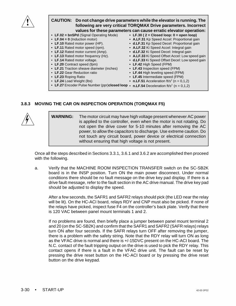
• START-UP 42-02-2P223-30
CAUTION: Do not change drive parameters while the elevator is running. Thefollowing are very critical TORQMAX Drive parameters. Incorrectvalues for these parameters can cause erratic elevator operation:
• LF.02 = bnSPd (Signal Operating Mode)• LF.04 = 0 (Induction motor)• LF.10 Rated motor power (HP).• LF.11 Rated motor speed (rpm). • LF.12 Rated motor current (Amp).• LF.13 Rated motor frequency (Hz).• LF.14 Rated motor voltage.• LF.20 Contract speed (fpm)• LF.21 Traction sheave diameter (inches)• LF.22 Gear Reduction ratio • LF.23 Roping Ratio• LF.24 Load Weight (lbs)• LF.27 Encoder Pulse Number (ppr)closed loop
• LF.30 ( 2 = Closed loop: 0 = open loop)• A.LF.31 Kp Speed Accel: Proportional gain• d.LF.31 Kp Speed Decel: Proportional gain• A.LF.32 Ki Speed Accel: Integral gain• d.LF.32 Ki Speed Decel: Integral gain• A.LF.33 Ki Speed Offset Accel: Low speed gain• d.LF.33 Ki Speed Offset Decel: Low speed gain• LF.42 High Speed (FPM)• LF.43 Inspection speed (FPM)• LF.44 High leveling speed (FPM)• LF.45 Intermediate speed (FPM)• n.LF.51 Acceleration ft/s2 (n = 0,1,2)• n.LF.54 Deceleration ft/s2 (n = 0,1,2)
WARNING: The motor circuit may have high voltage present whenever AC poweris applied to the controller, even when the motor is not rotating. Donot open the drive cover for 5-10 minutes after removing the ACpower, to allow the capacitors to discharge. Use extreme caution. Donot touch any circuit board, power device or electrical connectionwithout ensuring that high voltage is not present.
3.8.3 MOVING THE CAR ON INSPECTION OPERATION (TORQMAX F5)
Once all the steps described in Sections 3.3.1, 3.6.1 and 3.6.2 are accomplished then proceedwith the following.
a. Verify that the MACHINE ROOM INSPECTION TRANSFER switch on the SC-SB2Kboard is in the INSP position. Turn ON the main power disconnect. Under normalconditions there should be no fault message on the drive key pad display. If there is adrive fault message, refer to the fault section in the AC drive manual. The drive key padshould be adjusted to display the speed.
After a few seconds, the SAFR1 and SAFR2 relays should pick (the LED near the relaywill be lit). On the HC-ACI board, relays RDY and CNP must also be picked. If none ofthe relays have picked, inspect fuse F4 on the controller’s back plate. Verify that thereis 120 VAC between panel mount terminals 1 and 2.
If no problems are found, then briefly place a jumper between panel mount terminal 2and 20 (on the SC-SB2K) and confirm that the SAFR1 and SAFR2 (SAFR relays) relaysturn ON after four seconds. If the SAFR relays turn OFF after removing the jumper,there is a problem with the safety string. Note that the RDY relay will turn ON as longas the VFAC drive is normal and there is +/-15DVC present on the HC-ACI board. TheN.C. contact of the fault tripping output on the drive is used to pick the RDY relay. Thiscontact opens if there is a fault in the VFAC drive unit. The fault can be reset bypressing the drive reset button on the HC-ACI board or by pressing the drive resetbutton on the drive keypad.
42-02-2P22 START-UP • 3-31
b. All of the speed commands (acceleration, deceleration and the S curves) are adjustedby setting drive parameters using the drive key pad. A complete listing of theTORQMAX F5 Drive Parameters is found in Appendix L. A parameter sheet, listing theparameter settings as programmed by MCE, is shipped with each controller.
c. If required, install a temporary jumper between terminals 2 and 9 to bypass the doorlocks. If the car is on a final limit switch, place a jumper between terminals 2 and 16 tobypass the main safety string. Remember to remove these jumpers as soon aspossible.
d. For Flux Vector applications, the encoder must be mounted on the motor shaft and itsconnections must be complete according to the job prints at this time.
Auto-Tuning Induction Motors - For best performance with induction motors it is recommendto first perform the auto-tuning procedure as follows:
a. Make sure that the rated motor power (LF.10), rated motor speed (LF.11), rated motorcurrent (LF.12), rated motor frequency (LF.13), rated motor voltage (LF.14) and ratedpower factor (LF.15) are entered into the drive before you begin. If the power factor isnot on the name plate, use 0.90 as the value.
b. Remove one brake wire to prevent the brake from picking.
c. On the TORQMAX F5 drive keypad, set parameter LF.3 = S Lrn. This will start the learnprocess. The display will change to StArt.
d. With the controller on machine room inspection, pick and hold Up direction. The motorcontactor should pull in and the brake should not pick. Motor current will begin to flow,an audible noise in the motor will be heard, and the drive display will change to LS103.
The drive will measure various parameters in the motor as well as in the drive’s ownpower stage. During each measurement the display will change to signify what is beingmeasured. In the event of problems during the measurement phase, the factory can usethe codes to determine what is happening. Continue to hold the inspection switch ONuntil the drive displays “done”.
e. In the event that the drive cannot complete the measurements, two error messagesmay occur:• FAILd - the drive is not able to begin measurements due to a configuration error.
Consult the factory to resolve.• FAIL - the measurement sequence was interrupted, e.g., the inspection switch
was released prematurely, electrically the motor was not properly connected. Trythe measurement again.
f. When “done” is displayed, release the inspection switch. The drive will finish by makingseveral calculations, CALC is displayed, and updating the parameter values with themeasured values.
g. Reinstall the brake wire removed in step ‘b’ above.
• START-UP 42-02-2P223-32
NOTE: If the elevator does not run on Inspection, refer to Section 6.7,Troubleshooting the TORQMAX AC Drive.
Verify proper car movement and brake operation:
a. The Inspection Speed is set by drive parameter LF.43. Verify that the MACHINEROOM INSPECTION TRANSFER switch on the SC-SB2K board is in the INSPposition. Run the car by toggling the UP/DN toggle switch on the SC-SB2K board in thedesired direction using constant pressure. The PM and BK contactors should pick andthe car should move.
b. Verify that the car moves in the appropriate direction and the brake works properly.
• Open loop applications - If the car moves in the opposite direction, interchangetwo of the motor leads.
• Flux vector applications - Display the MOTOR CURRENT on the drive keypadby selecting parameter LF.93. Run the car on Inspection and check for one of thefollowing conditions:
1. If the car moves in the correct direction and the drive draws normal current(30% to 40% of motor FLA) proceed to step g.
2. If the car oscillates at zero speed, moves at slow speed, or trips the E.ENCfault on the drive, change parameter LF.28 setting (see parameters quickreference in Appendix L). This parameter will swap the encoder channelsinternally in the drive. It is not recommended to change the external encoderconnections as the drive has the capability of changing them throughsoftware.
3. If the motor draws normal current but the car moves in the oppositedirection, turn OFF the power and wait until there is no voltage present onthe DC bus. Then interchange two of the motor leads.
Turn ON the power and change parameter LF.28 setting (see parametersquick reference in Appendix L). The car should now move in the correctdirection and draw normal current.
c. Verify the inspection speed using a hand held tachometer. If the car moves slower thanthe set value of the Inspection speed parameter (LF.43) then verify the following:
• LF.11 Rated motor speed.• LF.20 Contract speed• LF.21 Traction sheave diameter.• LF.22 Gear reduction ratio. • LF.30 (2 = Close loop, 0 = Open loop)
If the gear reduction ratio is not available from the machine name plate, calculate thevalue by first measuring the motor revolutions using a marker on the motor shaft orbrake drum. Reduce the inspection speed by decreasing LF.43, then determine thenumber of motor shaft revolutions required to complete one revolution of the sheave.Calculate the gear reduction ration using the formula: Gear reduction ratio = MotorRPM / Sheave RPM. Enter the calculated value in parameter LF.22.
42-02-2P22 START-UP • 3-33
NOTE: If the car is not completely wired (temporary), check the following:• wire removed from panel mount terminal DCL• jumper placed between 2-bus and panel mount terminal DPM• wire removed from terminal 47 on the SC-SB2K board• jumper from 2 bus to terminal 36 on the SC-SB2K board• jumper from 2 bus to terminal 38 on the SC-SB2K board• jumper from 2 bus to panel mount terminal EPI (if present)
Note: The drive has the capability of estimating the gear reduction ratio. Run the car oninspection and read the value parameter LF.25, the gear ratio estimated by the drive.The value of LF.25 can be used for LF.22. However, the correct value of LF.22 is criticalfor overall system performance, therefore MCE/TORQMAX recommends calculating ormeasuring the gear reduction ratio and entering the calculated value in parameter LF.22if it is not available from the machine name plate.
Adjust the Inspection Speed for a comfortable inspection speed using parameter LF.43.For proper brake operation, adjust the SPD trimpot on the HC-ACI board to coordinatethe application of the speed command with the picking of the brake so that the car doesnot move under the brake or rollback at the start.
d. At this time the adjustment of the BDD trimpot on the HC-ACI board is also necessary.Otherwise the car may be stopping under the brake, causing a lot of current to beapplied to the motor that might cause arcing on the main contactor during the stop.
e. Test the safety by hand to make sure that it will hold the car.
f. To make sure that the Car Top Inspection switch is working properly, turn OFF the maindisconnect, remove the jumper between terminals 18 and ACCN, from step 3.3.1 (j),and reinstall the wire into terminal ACCN. Turn ON the main disconnect. Make sure thatthere is 115VAC on terminal ACCN with respect to terminal 1 when the car topinspection switch is in the NORMAL position. There should be no power on terminalACCN when the car top inspection switch is in the INSP position.
g. Stop the car so that the car top is accessible from the top hall door. Remove jumpersfrom the safety circuit. Run the car from the car top Inspection station. Verify thatthe SAFR1 relay drops out and the car stops when the Car Top Emergency StopSwitch is released. Also, by opening the Emergency Stop Switch while the car ismoving up or down, verify that the brake stops and holds the car.
h. Run the car through the hoist way, checking clearance and the door locks. When all ofthe doors are closed, remove the jumpers from terminals 2 and 9, and fromterminals 18 and ACCN (if present). Correct any problem with the door locks and thedoor closed contacts.
i. Temporarily take the car off of Inspection operation. If the LCD display does not showTEST MODE, see what message is being displayed and correct the problem. Forexample, if the indicators show that the car is on Fire Service Phase 1, a jumper mustbe connected between terminal 2 on the back plate and terminal 38 on the SC-SB2Kboard in order to run the car on Normal Operation. Remove the jumper once the FireService input is brought into the controller. Place the car back on Inspection.
• START-UP 42-02-2P223-34
NOTE: On modernizations it is easy to overlook the typical 40% counter-weighting.Always put a 40% load in the car and check for equal motor current (upverses down) at Inspection speed in the middle of the hoistway. Equalcurrent readings on the keypad display indicate that the counterweight isclose to the correct value. Take whatever steps are necessary to achieveproper counterweighting. This is especially important since many tractioninstallations do not have compensation cables or chains.
j. Check the counter weight balance. Make whatever corrections are necessary to makethe counter weight correct. Check to see what the counter weighing should be beforemaking any changes. If a drum machine is being used, follow the manufacturer’scounterweighting recommendation, and test the drum machine’s limit switches.
k. Turn OFF the power and reinstall the fuses that power terminals 2H and 2F. Theelevator controller installation should now be complete. Proceed to Section 4 FinalAdjustment.
42-02-2P22 FINAL ADJUSTMENT • 4-1
NOTE: Pin 1 on both the ribbon cable connector and the header on the HC-PCI/Oboard must match. These are designated with arrows on the connector andheader. Press the connector in until the latches snap, securing theconnector in place.
NOTE: Speed Pick Delay is not used on controllers with the TORQMAX drive. Turnthe SPD trimpot fully CCW and then set it 1/8 turn in the CW direction (seeSection 4.9.4 'd' and 'f').
SECTION 4FINAL ADJUSTMENT
4.0 GENERAL INFORMATION
At this point, all the steps in Section 3 should have been completed. Please read Section 5before proceeding; it explains the adjustment and troubleshooting tools available with thecomputer. This section is divided into three main parts:
1. Preparing to run on High Speed and Automatic operation - Section 4.1.
2. Final adjustment and testing procedures for controllers with:
• EMS, IDM Yaskawa or MagneTek (G5 / GPD515) AC drive - Sections 4.2 thru 4.4.
• MagneTek HPV 900 AC drive - Sections 4.5 thru 4.7.
• TORQMAX F4 AC drive - Sections 4.8 thru 4.10.
• Yaskawa F7 AC drive - Sections 4.11 thru 4.13.
• TORQMAX F5 AC drive - Sections 4.14 thru 4.16.
3. Compliance testing for ASME A17.1 2000 Code - Section 4.17
4.1 PREPARING TO RUN ON HIGH SPEED AND AUTOMATIC OPERATION
Move the car to the bottom landing on Inspection operation and turn OFF the main disconnect.Reinsert connector C1 into receptacle C1 on the HC-PCI/O board (if previously removed).
4.1.1 DOOR OPERATOR
If the door operator is not working, pull the door fuses and close the doors so the door clutchwill not hit any of the door lock rollers. Take whatever steps are necessary to keep theinstallation safe, but make sure that the car top is still accessible after closing all of the doors.Turn ON the AC power to the elevator.
4.1.2 TRIMPOT ADJUSTMENTS - In the process of preparing for running the elevator on high speedand automatic operation the following trimpots may require adjustment.
C SPD trimpot (Speed Pick Delay)on the HC-ACI board - This trimpot was adjusted inSection 3 on Inspection operation to coordinate the application of the speed command withthe picking of the brake. This trimpot may require readjustment when the car is adjustedfor High speed.
• FINAL ADJUSTMENT 42-02-2P224-2
NOTE: Read Section 5.1: The MC-PCA-OA2K Computer Panel - Your Tool forProgramming, Diagnostics and Data Communication and Section 5.3,Diagnostic Mode.
C BDD trimpot (Brake Drop Delay) on the HC-ACI board - This trimpot may needreadjustment. BDD controls the delay in dropping the brake so that the brake drops just ascar motion ceases.
C ILO trimpot (Inspection Leveling Overspeed) on the HC-ACI board - Not used on ASMEA17.1-2000 compliant controllers. Leave the ILO trimpot on the HC-ACI board fully CCW.Use the ILO trimpot on the SC-BASE or SC-BASER board to adjust the Inspection LevelingOverspeed threshold.
C ETS trimpot (Emergency Terminal Limit) on the HC-ACIF board - Not used on ASMEA17.1-2000 compliant controllers. Leave the ETS trimpot on the HC-ACIF board fullyCW. Use the ETS trimpot on the SC-BASE or SC-BASER board to adjust the EmergencyTerminal Limit Speed threshold.
4.1.3 DIAGNOSTIC MESSAGES AND INPUT/OUTPUT SIGNALS
To speed up the final adjustment and troubleshooting, become familiar with the Error StatusMessages (Table 5.2) and Input/Output signals (Flags and Variables, Tables 5.3 and 5.4) .
ON-BOARD DIAGNOSTICS - When the Elevator Controller’s Computer (MC-PCA-OA2K) isin DIAGNOSTIC MODE, with switches F1 - F8 in the down position, the LCD display providesa description of normal and abnormal conditions. When the LCD displays NORMAL, the systemis ready for normal operation. A complete listing of the status and error messages, theirmeaning, probable cause and needed response are found in Table 5.2, Error Status Messagesand Response Chart.
The computer displays abnormal conditions in the same priority that the computer evaluatesthem. For example, if the safety string is open and the system is also on Fire Service, thecomputer will first show that the safety string is open and will expect this problem to becorrected first. When the safety circuit problem has been corrected and the computer hasrecognized the safety input, the diagnostics will then show the Fire Service indication. Aftersuccessfully bringing in the Fire Service input, the computer will then show NORMAL on theLCD display, provided that the system is not on some other function such as IndependentService or Car Top Inspection operation. The display will show NORMAL only if everything isnormal. If the LCD display is showing any other message, an abnormal condition exists.
4.1.4 A FEW WORDS ABOUT ABSOLUTE FLOOR ENCODING
Absolute floor encoding (AFE) allows the controller to read encoding vanes or magnets at eachlanding and thereby identify the floor. Absolute floor encoding is provided as a standard.
All controllers are shipped with AFE as standard. If the car is not at a landing when power isturned ON, the controller will generate a down direction command and the car will move towardthe closest landing, provided that all abnormal conditions have been corrected. When the carreaches a landing and is within the Door Zone (relay DZ picked) with leveling completed (relaysLU1/2 and LD1/2 not picked) the controller reads the floor code vanes or magnets and correctsthe Position Indicator. If the car is on Automatic Operation, and if a home floor has beendesignated, the car will move to the home landing at this time. If the car is at a landing, withinthe Door Zone (relay DZ picked) with leveling completed (relays LU1/2 and LD1/2 not picked)when AC power is turned ON, the controller will read the floor code vanes or magnets at the
42-02-2P22 FINAL ADJUSTMENT • 4-3
CAUTION: The call terminals on the HC-PCI/O and HC-CI/O-E board should neverbe connected to any of the power terminals (such as 2, 3, 4, etc.). Ifthis happens and the call is turned on, it will blow the resistor-fuse ortriac which plugs into the Call board. Later versions of these boardsmay have plug-in zener diodes. These parts are designed to be field re-placeable and spares are provided in unused positions on the Callboard, or are available from MCE. DO NOT JUMPER THESE PLUG-INCOMPONENTS AS IT MAY DESTROY THE BOARD OR OTHERCONTROLLER COMPONENTS. If any of these components shouldblow, FIND OUT WHY instead of constantly replacing them, as theconstant faults can eventually damage the board.
landing and correct the Position Indicator. Again, if a home floor has been designated the carwill move to this landing to park.
4.1.5 REGISTERING CAR CALLS
In the process of making final adjustments to the controller, you will be asked to register carcalls periodically. A call or series of calls can be registered at the controller by momentarilyplacing a jumper between terminal 1 (system common) and the desired car call terminal orterminals on the HC-PCI/O or HC-CI/O-E board, and then between terminal 2 and terminal 45to allow the car to travel to each call. The car may move immediately after the first call is putin, or it may wait several seconds before moving.
4.1.6 TEST MODE OPERATION
The purpose of Test mode is to allow easy and convenient operation of the car so that the finaladjustments can be made without cycling the doors. When the elevator is operated in the TESTmode, the elevator doors do not open. The door open relays are disconnected automaticallyduring Test mode operation.
The car is put into TEST mode by placing the TEST/NORMAL switch on the SC-SB2K (MainSafety Relay) board in the TEST position. Note that when the TEST/NORMAL switch is in theTEST position, it puts the car into Test mode, provided that the Car Top Inspection and RelayPanel Inspection switches are in the OFF or normal positions. In that case, the LCD should beshowing TEST MODE and not NORMAL. If the expected indication is not displayed, check tosee what message is being displayed and correct the problem. Operation while in Test modeshould be easy to understand by knowing the following:
a. Every time the car stops, a non-interference timer must elapse before the car can moveagain (the car will not move unless there is another car call). Note that after the timer haselapsed, the car will move immediately as soon as the next car call is placed (the car willnot move if the system is a single button collective system and there is no jumper fromterminal 2 to terminal 45). Placing a car call right after the car stops will require the non-interference timer to elapse before the car can move again.
b. Simply having one or more car calls registered will not necessarily cause the car to move.It will be necessary to jumper terminal 2 to terminal 45 to create a Door Close Button inputto get the car to move. If the car is not a single button collective but is a selective-collective,the jumper from terminal 2 to 45 will not be necessary. Leave a jumper connected fromterminal 1 to the last car call in the line of calls that have been placed. This will create aconstant pressure signal on the car call which is an alternate means of creating a DoorClose Button signal to get a car that is on Independent Service to leave the landing.However, the jumper from terminal 2 to terminal 45 may be more convenient.
• FINAL ADJUSTMENT 42-02-2P224-4
CAUTION: Verify the critical drive parameter settings as described in Section3.4.2. Incorrect values for these parameters can cause erraticelevator operation.
CAUTION: It is very important that drive parameters only be changed when thecar is stopped and the elevator is on Inspection or Test operation.The Programming mode has to be accessed in order to change adrive parameter. The drive will not function in Programming mode, itmust be in Operation mode to run the elevator.
CAUTION: The drive will trip on OPE40 or OPE41 fault if the following conditionsare not met: parameters D1-02 > D1-07 > D1-03 > D1-05 > 0.0 butless than the maximum specified value.
c. If a jumper from terminal 1 is touched to the car call input for the floor where the car islocated, it will reestablish the non-interference timer and it must elapse before the car canmove again.
d. If the elevator is trying to level, it will not pick high speed and leave the landing until it hascompleted the leveling process. Drive Unit speed adjustments and direction limits atterminal landings may cause this problem.
e. If any of the inputs that open the door are active (Safety Edge On, Photo Eye On, Car Callinput grounded to 1 for the floor matching the Position Indicator, etc.) the car will not leavethe landing.
f. Both slowdown switch inputs (terminals 11 and 13) should never be dead at the same timewhen the doors are closed and locked and the safety circuit is good.
4.2 EXPLANATION OF G5 / GPD515 DRIVE PARAMETERS AND S CURVES
For controllers with the MagneTek HPV 900 AC Drive, see Sections 4.5 thru 4.7 and 4.17.For controllers with the TORQMAX F4 AC Drive, see Sections 4.8 thru 4.10 and 4.17.For controllers with the Yaskawa F7 AC Drive, see Sections 4.11 thru 4.13 and 4.17.For controllers with the TORQMAX F5 AC Drive, see Sections 4.14 thru 4.16 and 4.17.
While setting up the drive, set ASME A17.1-2000 REDUNDANCY BYPASS = BYPASS ON fortwo hours of run time with the ASME A17.1-2000 functions bypassed (see section 5.6.5.1).
Before attempting to bring the car up to contract speed, or making any adjustments, it isimportant to verify the following control parameters in the VFAC Drive Unit. It is very importantto become familiar with drive keypad operation to access the drive program. Review the useof the Digital Operator (drive keypad) in the VFAC Drive manual.
4.2.1 SETTING THE SPEED LEVELS
There are five speed levels (D1 parameters) that can be set in the drive software (see Table4.1 and Figure 4.1). The drive software will not accept data entry to any D1 parameters otherthan those listed in Table 4.1. If you change a drive parameter and there is an OPE40 fault, theonly way to correct this fault is to access the PROGRAM mode again and access the particularD1-D9 parameter. You must enter a correct value and then reset the drive by pushing the drivefault reset button on the HC-ACI board or by pressing the drive reset button on the drive keypad.
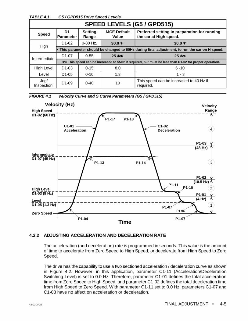
42-02-2P22 FINAL ADJUSTMENT • 4-5
Velocity (Hz)
Time
Zero Speed
Level D1-05 (1.3 Hz)
High LevelD1-03 (8 Hz)
IntermediateD1-07 (45 Hz)
High SpeedD1-02 (60 Hz)
P1-04
C1-01 Acceleration
C1-02 Deceleration
P1-13 P1-14
P1-11P1-10
P1-07P1-06
P1-07
P1-17 P1-18
P1-03 (48 Hz)
P1-02 (10.5 Hz)
P1-01 (4 Hz)
1
2
3
4
VelocityRange
TABLE 4.1 G5 / GPD515 Drive Speed Levels
SPEED LEVELS (G5 / GPD515)
Speed D1Parameter
SettingRange
MCE DefaultValue
Preferred setting in preparation for runningthe car at High speed.
HighD1-02 0-80 Hz. 30.0 w 30.0 w
w This parameter should be changed to 60Hz during final adjustment, to run the car on H speed.
Intermediate D1-07 0-55 25 ww 25 ww ww This speed can be increased to 55Hz if required, but must be less than D1-02 for proper operation.
High Level D1-03 0-15 8.0 6 -10
Level D1-05 0-10 1.3 1 - 3
Jog/Inspection
D1-09 0-40 10 This speed can be increased to 40 Hz ifrequired.
FIGURE 4.1 Velocity Curve and S Curve Parameters (G5 / GPD515)
4.2.2 ADJUSTING ACCELERATION AND DECELERATION RATE
The acceleration (and deceleration) rate is programmed in seconds. This value is the amountof time to accelerate from Zero Speed to High Speed, or decelerate from High Speed to ZeroSpeed.
The drive has the capability to use a two sectioned acceleration / deceleration curve as shownin Figure 4.2. However, in this application, parameter C1-11 (Acceleration/DecelerationSwitching Level) is set to 0.0 Hz. Therefore, parameter C1-01 defines the total accelerationtime from Zero Speed to High Speed, and parameter C1-02 defines the total deceleration timefrom High Speed to Zero Speed. With parameter C1-11 set to 0.0 Hz, parameters C1-07 andC1-08 have no affect on acceleration or deceleration.
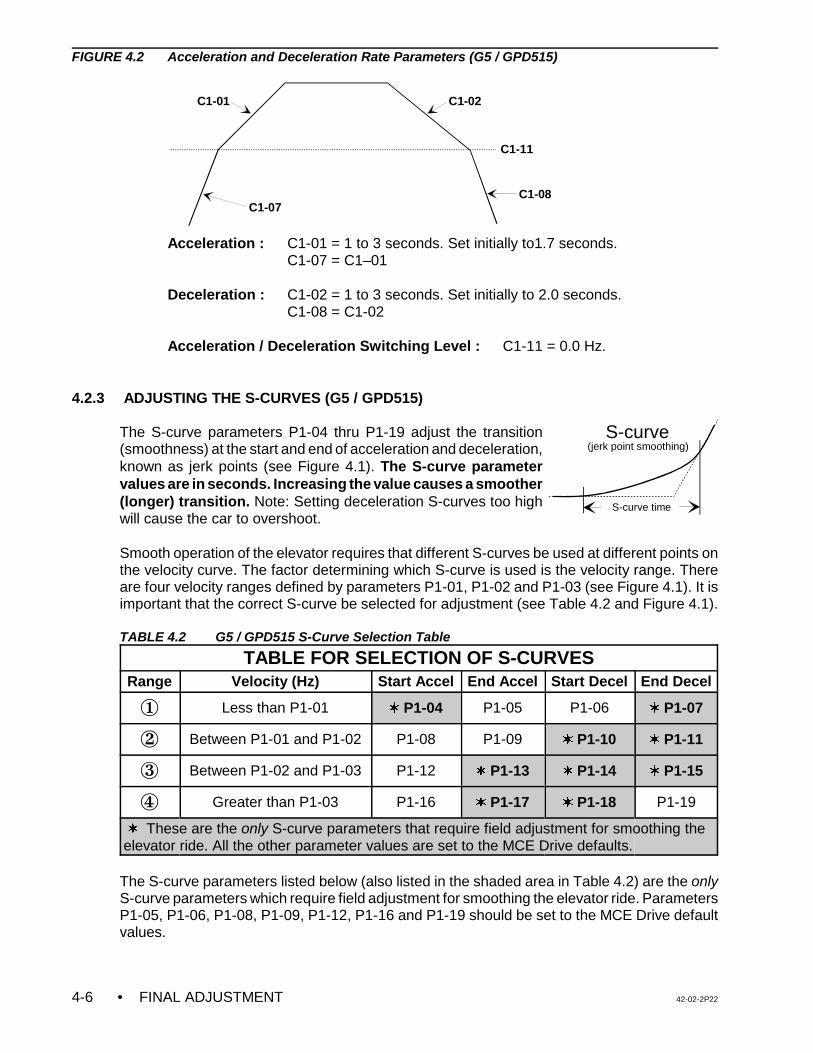
• FINAL ADJUSTMENT 42-02-2P224-6
C1-07
C1-01 C1-02
C1-08
C1-11
S-curve time
(jerk point smoothing)S-curve
FIGURE 4.2 Acceleration and Deceleration Rate Parameters (G5 / GPD515)
Acceleration : C1-01 = 1 to 3 seconds. Set initially to1.7 seconds. C1-07 = C1–01
Deceleration : C1-02 = 1 to 3 seconds. Set initially to 2.0 seconds.C1-08 = C1-02
Acceleration / Deceleration Switching Level : C1-11 = 0.0 Hz.
4.2.3 ADJUSTING THE S-CURVES (G5 / GPD515)
The S-curve parameters P1-04 thru P1-19 adjust the transition(smoothness) at the start and end of acceleration and deceleration,known as jerk points (see Figure 4.1). The S-curve parametervalues are in seconds. Increasing the value causes a smoother(longer) transition. Note: Setting deceleration S-curves too highwill cause the car to overshoot.
Smooth operation of the elevator requires that different S-curves be used at different points onthe velocity curve. The factor determining which S-curve is used is the velocity range. Thereare four velocity ranges defined by parameters P1-01, P1-02 and P1-03 (see Figure 4.1). It isimportant that the correct S-curve be selected for adjustment (see Table 4.2 and Figure 4.1).
TABLE 4.2 G5 / GPD515 S-Curve Selection Table
TABLE FOR SELECTION OF S-CURVESRange Velocity (Hz) Start Accel End Accel Start Decel End Decel
Î Less than P1-01 w P1-04 P1-05 P1-06 w P1-07
Ï Between P1-01 and P1-02 P1-08 P1-09 w P1-10 w P1-11
Ð Between P1-02 and P1-03 P1-12 w P1-13 w P1-14 w P1-15
Ñ Greater than P1-03 P1-16 w P1-17 w P1-18 P1-19
w These are the only S-curve parameters that require field adjustment for smoothing theelevator ride. All the other parameter values are set to the MCE Drive defaults.
The S-curve parameters listed below (also listed in the shaded area in Table 4.2) are the onlyS-curve parameters which require field adjustment for smoothing the elevator ride. ParametersP1-05, P1-06, P1-08, P1-09, P1-12, P1-16 and P1-19 should be set to the MCE Drive defaultvalues.
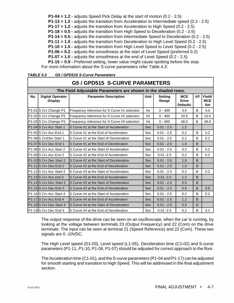
42-02-2P22 FINAL ADJUSTMENT • 4-7
P1-04 = 1.2 - adjusts Speed Pick Delay at the start of motion (0.2 - 2.5)P1-13 = 1.2 - adjusts the transition from Acceleration to Intermediate speed (0.2 - 2.5)P1-17 = 1.2 - adjusts the transition from Acceleration to High Speed (0.2 - 2.5)P1-18 = 0.5 - adjusts the transition from High Speed to Deceleration (0.2 - 2.5)P1-14 = 0.5 - adjusts the transition from Intermediate Speed to Deceleration (0.2 - 2.5)P1-11 = 1.0 - adjusts the transition from Deceleration to High Level Speed (0.2 - 2.5)P1-10 = 1.5 - adjusts the transition from High Level Speed to Level Speed (0.2 - 2.5)P1-06 = 0.2 - adjusts the smoothness at the start of Level Speed (preferred 0.2)P1-07 = 1.0 - adjusts the smoothness at the end of Level Speed (0.2 - 2.5)P1-15 = 0.9 - Preferred setting, lower value might cause spotting before the stop.
For more information about the S-curve parameters refer Table 4.3:
TABLE 4.3 G5 / GPD515 S-Curve Parameters
G5 / GPD515 S-CURVE PARAMETERS The Field Adjustable Parameters are shown in the shaded rows.
No. Digital OperatorDisplay
Parameter Description Unit SettingRange
MCEDrive
Defaults
V/f Field/MCESet
P1-01 S Crv Change P1 Frequency reference for S Curve #1 selection Hz 0 - 400 4.0 B 4.0
P1-02 S Crv Change P2 Frequency reference for S Curve #2 selection Hz 0 - 400 10.5 B 10.5
P1-03 S Crv Change P3 Frequency reference for S Curve #3 selection Hz 0 - 400 48.0 B 48.0
P1-04 S Crv Acc Start 1 S Curve #1 at the Start of Acceleration Sec 0.01 - 2.5 1.2
P1-05 S Crv Acc End 1 S Curve #1 at the End of Acceleration Sec 0.01 - 2.5 0.2 B 0.2
P1-06 S CrvDec Start 1 S Curve #1 at the Start of Deceleration Sec 0.01 - 2.5 0.2 B 0.2
P1-07 S Crv Dec End 1 S Curve #1 at the End of Deceleration Sec 0.01 - 2.5 1.0 B
P1-08 S Crv Acc Start 2 S Curve #2 at the Start of Acceleration Sec 0.01 - 2.5 0.2 B 0.2
P1-09 S Crv Acc End 2 S Curve #2 at the End of Acceleration Sec 0.01 -2.5 0.2 B 0.2
P1-10 S Crv Dec Start 2 S Curve #2 at the Start of Deceleration Sec 0.01 - 2.5 1.5 B
P1-11 S Crv Dec End 2 S Curve #2 at the End of Deceleration Sec 0.01 - 2.5 1.0 B
P1-12 S Crv Acc Start 3 S Curve #3 at the Start of Acceleration Sec 0.01 - 2.5 0.2 B 0.2
P1-13 S Crv Acc end 3 S Curve #3 at the End of Acceleration Sec 0.01 -2.5 1.2 B
P1-14 S Crv Dec Start 3 S Curve #3 at the Start of Deceleration Sec 0.01 - 2.5 0.5 B
P1-15 S Crv Dec End 3 S Curve #3 at the End of Deceleration Sec 0.01 - 2.5 0.9 B 0.9
P1-16 S Crv Acc Start 4 S Curve #4 at the Start of Acceleration Sec 0.01 - 2.5 0.2 B 0.2
P1-17 S Crv Acc End 4 S Curve #4 at the End of Acceleration Sec 0.01 - 2.5 1.2 B
P1-18 S Crv Dec Start 4 S Curve #4 at the Start of Deceleration Sec 0.01 - 2.5 0.5 B
P1-19 S Crv Dec End 4 S Curve #4 at the End of Deceleration Sec 0.01 -2.5 0.2 B 0.2
The output response of the drive can be seen on an oscilloscope, when the car is running, bylooking at the voltage between terminals 23 (Output Frequency) and 22 (Com) on the driveterminals. The input can be seen at terminal 21 (Speed Reference) and 22 (Com). These twosignals are 0 -10VDC.
The High Level speed (D1-03), Level speed (L1-05), Deceleration time (C1-02) and S-curveparameters (P1-11, P1-10, P1-06, P1-07) should be adjusted for correct approach to the floor.
The Acceleration time (C1-01), and the S-curve parameters (P1-04 and P1-17) can be adjustedfor smooth starting and transition to High Speed. This will be addressed in the final adjustmentsection.
• FINAL ADJUSTMENT 42-02-2P224-8
4.3 FINAL ADJUSTMENTS (G5 / GPD515)
For controllers with the MagneTek HPV 900 AC Drive, see Sections 4.5 thru 4.7 and 4.17.For controllers with the TORQMAX F4 AC Drive, see Sections 4.8 thru 4.10 and 4.17.For controllers with the Yaskawa F7 AC Drive, see Sections 4.11 thru 4.13 and 4.17.For controllers with the TORQMAX F5 AC Drive, see Sections 4.14 thru 4.16 and 4.17.
4.3.1 FINAL PREPARATION FOR RUNNING ON AUTOMATIC OPERATION (G5 / GPD515)
a. Temporarily take the car off of Inspection operation. If the LCD display does not showTEST MODE, see what message is being displayed and correct the problem. Forexample, if the indicators show that the car is on Fire Service Phase 1, a jumper mustbe connected between terminal 2 on the back plate and terminal 38 on the SC-SB2Kboard in order to run the car on Normal Operation. Remove the jumper once the FireService input is brought into the controller. Place the car back on Inspection.
b. Move the car to the bottom terminal landing. Check to see if the DZ relay is picked. Ifnot, move the car on Inspection to place it in the Door Zone.
4.3.2 SWITCHING TO AUTOMATIC OPERATION (G5 / GPD515)
Place the Relay Panel Inspection switch in the OFF position. If the car is not at a landing it willmove to a landing at high leveling speed. If the car is at a landing but not in the door zone,leveling relays L and either LU1/2 or LD1/2 should pick and the car should perform a relevel.If the relevel in not successful, check the following:
C If the brake picks and the car is trying to level but is not able to, it may be necessary toadjust the Level Speed parameter (D1-05) on the G5 / GPD515 AC Drive to get the carto move.
C If leveling relays L and LD1/2 are picked, but the brake and other relays are not, thedown direction limit switch may be preventing the leveling down operation.
C If the car is trying to level, it will not leave the landing for a call until the leveling iscomplete. Move the limit switch if necessary.
The Status Indicator lights should now display the indication for Independent Service operation.At this time the Position Indicator should match the actual car location. Note that all of thePosition Indicators and direction arrows are conveniently displayed on the controller. All thecalls are also displayed on the controller.
4.3.3 BRAKE ADJUSTMENT FOR 125% LOAD (G5 / GPD515)
Put the car on Inspection at the bottom landing. Put 2/3 of a contract load in the car. Beginadding weights in 50 or 100 pound increments and move the car up and down on Inspectioneach time. Adjust the brake tension to stop and hold 125% of a contract load by tripping a stopswitch open while running down on Inspection. Hold the DOWN button in while tripping openthe stop switch (preferably on the Inspection station). KEEP THE CAR NEAR THE BOTTOMAS IT IS LIKELY TO SLIDE THROUGH THE BRAKE ONTO THE BUFFERS. If the VFAC DriveUnit trips off when the car is going down, but not while it is going up, refer to the manual for theVFAC Drive Unit and look up the failure indicated on the Drive display. If an over-voltage faultis indicated, there may be a problem in the regeneration (or braking) resistors or the brakingmodule (if one is provided). If this problem cannot be solved, call MCE Technical Support.Remove all test weights from the car.
42-02-2P22 FINAL ADJUSTMENT • 4-9
NOTE: It is very important that the drive parameters only be changed when the caris stopped and the elevator is on Inspection or Test operation so that thereis no demand. To change a drive parameter, the Programming mode hasto be accessed. When the drive is in Programming mode it will not function.The drive has to be in Operation mode to run the elevator.
NOTE: The active speed frequency in Hz will show on the drive key padcorresponding to the setting of the D parameters.
4.3.4 BRINGING THE CAR UP TO HIGH SPEED (G5 / GPD515)
a. Verify that all the steps described in Sections 4.1 and 4.2 regarding the adjustmentsand specifically the drive parameters are complete.
b. Register a car call one floor above the car. The High speed relay (H) should pick andthe drive keypad should read 30HZ as the car attempts to start. If the car runs normally,commence multi-floor runs and slowly increase the High speed parameter (D1-02) untilcontract speed is achieved. If the motor is designed for 60 Hz, contract speed shouldbe reached when the keypad displays 60Hz. Some motors are designed for 50Hz or40Hz. In those applications parameter D1-02 must be set according to the designedmotor frequency, 50Hz or 40Hz. Contract speed should be reached when the keypaddisplay reads 50Hz or 40Hz, respectively.
c. The Position Indicator will step at the slowdown distance from the next floor. Afterstepping occurs, High speed is dropped and the car should rapidly decelerate to HighLevel speed. Reduce the High Level speed parameter (D1-03 ) so that the car runs atabout 10 - 20 fpm or at a reasonable speed (use your personal judgment). Six inchesbefore the floor at which the car is to stop, High Level speed is dropped and the cardecelerates to Level speed. The Level speed can be adjusted using parameter D1-05so that the car levels into the floor and stops. Level speed should be 7 - 12 fpm, or areasonable leveling speed (use personal judgement). If the car re-levels frequently onceLevel speed is adjusted satisfactorily, spread apart the LU and LD sensors or switchesin the landing system to provide enough Dead Zone.
d. Adjust the SPD (Speed Pick Delay) trimpot by first turning it far enough clockwise sothat the empty car rolls back in the direction of the counterweight (if it can). Then adjustSPD so that the brake is fully picked just as the motor first moves. The goal is to delaylong enough to avoid moving the motor before the brake is fully lifted, but not so longas to allow the car to roll back.
e. Run the car again and verify that the car will start, accelerate, decelerate and run atHigh Level and Level speeds into the floor and stop. Place calls for all of the landings.Verify that all of the calls work. Verify the operation and placement of all vanes ormagnets and vane or magnet switches and verify that the car steps the PositionIndicators correctly. The slowdown distance for the elevator is measured from the pointwhere the STU sensor (or STD sensor, if going down) is activated by a metal vane ormagnetic strip to the position where the car is stopped at the floor with the DZ sensorcentered on the leveling target with LU or LD sensors not engaged.
The slowdown distance was chosen to give a reasonable deceleration rate. Continueto make two-floor runs and slowly increase High speed until Contract Speed is reached.It may be necessary to adjust the Deceleration rate parameters(C1-02 and C1-08) toget the car to approach the floor correctly as the car speed increases. Adjust the
• FINAL ADJUSTMENT 42-02-2P224-10
NOTE: To observe the commanded speed and the drive output with anoscilloscope or a chart recorder, monitor drive terminals 21 and 23 withrespect to 22. These are 0 -10 VDC signals. Take all necessaryprecautions while measuring the voltage signals.
CAUTION: Most oscilloscopes have a grounding pin on their power plug. Werecommend defeating the grounding pin with one of the commonlyavailable ground isolation adapter plugs so that the case of theoscilloscope is not at ground potential, but at whatever potential thenegative probe lead is connected to. TREAT THE CASE OF THEOSCILLOSCOPE AS A LETHAL SHOCK HAZARD, DEPENDINGON WHERE THE NEGATIVE PROBE IS CONNECTED. Thisrecommendation is being made because the ground potential on thegrounding pin of the power outlet may not be the same as thecontroller cabinet ground. If it is not, substantial ground loop currentmay flow between the negative probe and the power plug groundingpin which can ruin the oscilloscope.
Acceleration rate parameters(C1-01 and C1-07) until the desired acceleration isachieved. Several runs may be required to obtain optimum acceleration. Theacceleration rate should be about the same as the deceleration rate.
f. If the job is a modernization, contract speed should correspond to a VFAC Drive outputfrequency of 60 Hz (± 8 Hz). The frequency may vary with direction and load. Arrangethe VFAC Drive Unit to display the output frequency to verify this.
g. To achieve a proper start, without rollback (or snapping away from the floor), a variabledelay in the application of the speed signal has been provided by adjusting trimpot SPD(Speed Pick Delay). Trimpot SPD must be adjusted to let the brake just clear the brakedrum before attempting to accelerate the car. Do this with an empty car. The correctsetting will be obvious by watching the Drive sheave. This was adjusted previously;however, check trimpot SPD again and make adjustments if necessary. The responseof the car can be monitored using an oscilloscope by measuring the voltage on the driveterminals 21 and 23 with respect to 22. These signals are 0-10 volt. Terminal 21 isprogrammed for the drive input speed reference and terminal 23 is programmed for thedrive output frequency.
For flux vector applications only: To improve the car's response the following driveparameters can be adjusted as described below, provided that the Motor data slipparameter (E2-02) and Motor No load current ( E2-03) are set correctly.
1. ASR Proportional Gain 1, ( C5-01) - The ASR Proportional Gain 1 controls theresponse of the car to the speed command. Increasing C5-01 results in tightercontrol. A low value may result in a speed deviation error. A too high value mayresult in oscillation.
2. ASR Integral Time 1, ( C5-02) - The ASR Integral Time 1 adjusts the amount oftime for the drive to respond to a change in speed command. Response time isincreased when the C5–02 is decreased. However, the car may becomeunstable if the ASR Integral Time is set too low.
42-02-2P22 FINAL ADJUSTMENT • 4-11
NOTE: If the job has Intermediate Speed (SHR Relay), first adjust the multi-floorruns. Then make one floor runs and adjust parameter D1-07 to reach thecorrect intermediate speed. Do not change any other parameter except P1-13 or P1-14, if required, as described in Figure 4.1
3. Parameters C5-03 ( ASR P Gain 2) , and C5-04 ( ASR Integral Time 2) are notused and must be set to the factory default values.
h. The car should be running well now, except possibly for the final stop. Since the speed
reference goes to zero when the car stops, the VFAC Drive Unit will cause the machineto stop electrically. Enough delay in the setting of the brake (BDD) will have to beprovided to allow the sheave to stop turning before setting the brake firmly on the brakedrum.
When the elevator slows down to leveling speed and travels to door zone, the speedcommand will drop to zero before the brake drops. This is adjustable by the BDD (BrakeDrop Delay) trimpot. For open loop applications, the car stop will be accomplished withinjection braking current supplied by the VFAC Drive Unit at the end of the run. Thestrength and duration of this DC braking current is programmable using parametersB2-02 and B2-04 on the VFAC Drive Unit and, to start with, should be set at 50 and 0.5respectively (50% current and 0.5 second duration). A sharper and stronger electricstop is provided by increasing B2-02 and a softer stop by decreasing B2-02. Theduration of the DC injection braking must be less than the dropout time of thecontactor(s) which disconnect the motor from the VFAC Drive Unit. This assumes thatthe contactor(s) will open under zero current conditions. For Flux Vector applications,DC injection braking is not required for stopping. All B2 parameters must be set to thefactory default settings.
With the method of providing an electric stop as indicated above, provide a delay indropping the brake by turning the BDD (Brake Drop Delay) trimpot clockwise. The ideais to hold the brake up long enough to allow the motor to be stopped electrically andthen drop the brake immediately the instant the motor has stopped.
If there is too long of a delay before dropping the brake, the control system will releaseits control of the motor and the motor will drift briefly in the direction of the load beforethe brake is forced to drop by the PT relays. The BDD trimpot controls the dropping ofthe brake through the BE relay. Move the LU and LD sensors or switches closertogether (or further apart) so the car stops at the same location, up or down. Then movethe floor (leveling) magnet strips or vanes so the car stops accurately at each floor.
i. The adjustment is almost complete. The acceleration rate setting on drive parameterC1-01 should be at least as great as the deceleration rate parameter C1-02, but itshould not be so high that it substantially exceeds the value of C1-02. Excessiveacceleration will probably cause the VFAC Drive Unit circuits to saturate and therefore,lose control of the car. Ideally, the slope of the acceleration in volts per second shouldbe equal to the slope of the deceleration. Note the present value of the C1-02parameter. Increase the value of C1-02 and run the car. Continue to increase the valueof C1-02 until the car overshoots the floor, requiring a relevel operation. Observe theresponse of the car to verify a stable releveling operation. Return the value of the C1-02parameter to its original value so that the approach to the floor is the same as before.After the car stops, check the empty car releveling operation by placing a jumperbetween terminals 18 and 26 to cause an up level after which the car will stop due topicking the LD (Down Level) switch. Remove the jumper from terminals 18 and 26 and
• FINAL ADJUSTMENT 42-02-2P224-12
the car will level down against the counterweight. Make sure that it does not stall. If thecar stalls, you might have to increase the leveling speed.
4.3.5 LOAD TESTING (G5 / GPD515)
a. Begin adding test weights to the car in 100 or 200 pound increments all the way up tothe rated load. Observe the VFAC Drive Unit current on its display and check to see ifthere is an OC (Over Current) error indication as the car accelerates to full speed. If so,this indicates that the VFAC unit is being pushed close to its limits and may require oneor more of the following actions:
1. The requested acceleration rate may be excessive. Try reducing theacceleration rate by increasing parameter C1-01. The more time spent inacceleration, the lower the current demand.
2. A more gradual transition from acceleration to high speed may be made byincreasing drive parameter P1-17 for contact speed and P1-13 for intermediatespeed.
3. For Open loop applications - Adjust parameter C4-01(Torque CompensationGain) between 1.0 - 2.0. The maximum setting for this parameter is 2.5. Displaythe output current on the drive key pad in the Operation mode by pressing theup arrow twice. The drive keypad will display OUTPUT CURRENT U1-03= 0.0A.The G5 drive can provide 150% of its full load rated current for 1 minute. Runthe car and monitor the current on the drive keypad. If the motor is stalling butdoes not trip on OC faults, and if the value of the output current is morethan or close to the motor rated current but less than the maximum driveoutput current, check the motor winding configuration. Most elevatormotors are connected in Y configuration. But sometimes the DELTAconfiguration is used in order to pick the full load. The motor manufacturer’srecommendations must be taken into consideration. If the field survey data wasinaccurate, the Drive Unit may be undersized in relation to the motor. Call MCETechnical Support so that the job data can be reviewed.
For Flux Vector Applications -The Torque Compensation Gain parameter isnot available for flux vector applications. ASR Tuning (C5 parameters), asdescribed in Section 4.3.4 (g), can be adjusted to pick the full load.
4. The motor may be underrated. It may be possible to get excellent results if thespeed is reduced slightly.
5. The elevator may be improperly counter weighted. This possibility should bethoroughly investigated.
6. Make a copy of the Table in Appendix B, Quick Reference for G5 / GPD515Drive Parameters and use the digital operator on the VFAC Drive Unit to lookup and write down every parameter value as programmed in the unit. Use thisas a reference when calling MCE to review the data.
b. If there is a full load in the car and there is trouble slowing in the down direction, or ifthe VFAC Drive Unit is tripping off and there is an OV (over voltage) fault displayed, itmay mean that there is a problem with the regeneration (braking) resistors and/or thebraking unit (if supplied separately). Check for DC bus voltage. There are two methodsto check the DC bus voltage as described below:
42-02-2P22 FINAL ADJUSTMENT • 4-13
WARNING: The following tests should be performed only by qualified elevatorpersonnel skilled in final adjustment and inspections.
1. Through the drive display: When the drive is in Operation mode, press the uparrow until Monitor function U1 is displayed, press enter and then use the uparrow to access the U1-07 (DC bus voltage). Then run the elevator and watchthe voltage reading.
2. Actual measurement of voltage: Use extreme care when measuring the DCvoltage across the drive power terminals (-) and (+ 2 or +3) under the aboveconditions.
If the bus voltage is 325 VDC (for a 230 VAC motor) or 650 VDC (for 460 VAC motor), and ifthere is no voltage measured across the braking resistors while the car is slowing with a fullload going down or empty car up, there may be a wiring problem, or a defective braking unit(if provided). Be sure to investigate this thoroughly. These resistors perform the task ofregulating car speed during a full load down or empty car up run (regeneration).
4.4 FINAL ELEVATOR INSPECTION PROCEDURE (G5 / GPD515)
For controllers with the MagneTek HPV 900 AC Drive, see Sections 4.5 thru 4.7 and 4.17.For controllers with the TORQMAX F4 AC Drive, see Sections 4.8 thru 4.10 and 4.17.For controllers with the Yaskawa F7 AC Drive, see Sections 4.11 thru 4.13 and 4.17.For controllers with the TORQMAX F5 AC Drive, see Sections 4.14 thru 4.16 and 4.17.
4.4.1 INSPECTION LEVELING OVER SPEED TEST (G5 / GPD515)
Note: Before performing tests 4.4.1 and 4.4.3, please remove the jumper between pins labeled2KBP1 and 2KBP2 on the SC-BASE board. Also rotate trimpots ILO, ETS and COS fully CW.
The SC-BASE board is equipped with an independent low speed monitoring system which canshut down the system if the car runs faster than a trimpot adjustable preset speed on Car TopInspection, Hoistway Access or Leveling operation. The monitoring system is active when theLeveling (LU1/LU2, LD1/LD2) relays are picked or when the Access/Inspection relay (IN1) isdropped out. The trimpot is labeled ILO (Inspection Leveling Overspeed) and is located on theSC-BASE board. The circuit looks at pulses coming from the speed sensor, sensing a magneton the motor shaft or brake drum, etc. Calibrate this circuit as follows:
a. Place the car on Inspection operation by placing the MACHINE ROOM INSPECTIONTRANSFER switch in the INSP position on the SC-SB2K.
b. Run the car on Inspection (up or down) and record the actual values for parameter D1-09 ________. D1-09 must be returned to the original value when this test is complete.Now, run the car on Inspection and adjust the IN speed (Parameter D1-09) for thepreferred maximum leveling speed (something below 150 fpm).
c. While running the car at the adjusted maximum leveling speed, slowly turn the ILOtrimpot CCW until the ILO1/ILO2 indicators turn ON. The car should come to animmediate stop and the MC-PCA-OA2K LCD display should read “ILO Fault”. The ILOfault will self reset in a moment.
d. Now set D1-09 to a lower value. Run the car on Inspection and increase the inspection
speed by increasing parameter D1-09 to show that this low speed safety monitor circuit
• FINAL ADJUSTMENT 42-02-2P224-14
will trip at no higher than 150 fpm (or no higher than the desired maximum inspectionspeed). Check this in both directions. The overspeed monitor is now calibrated for lessthan 150 fpm for Access, Inspection and Leveling. Return parameter D1-09 to thevalue recorded in Step (b).
4.4.2 TERMINAL SLOWDOWN LIMIT SWITCHES (G5 / GPD515)
Make sure that the terminal slowdown limit switches are working properly by doing thefollowing:
a. Place the TEST/NORMAL switch on the SC-SB2K board in the TEST position.
b. Disconnect and label the wires from terminals 71 ( STU) and 72 ( STD) on the SC-SB2K board.
c. Register calls for the terminal landings (top and bottom) from the controller. The carshould make a normal slowdown at both terminal landings except that there may be aslight relevel, which is okay. If the car goes more than an inch past the floor, move theslowdown limit until the approach is normal.
d. Reconnect the wires to terminals 71(STU) and 72 (STD) on the SC-SB2K board andreturn theTEST/NORMAL switch to the NORMAL position.
4.4.3 EMERGENCY TERMINAL LIMIT SWITCH MONITOR (G5 / GPD515)
All jobs under the requirements of ANSI A17.1 -2000 Articles 2.25.4.1. or 2.25.4.2 must havea means to insure that the car speed is below contract speed after opening the associatedETS limit switches. The emergency terminal limit switch monitor performs this function.
The SC-BASE board carries out ETS monitoring functions via a speed senor that monitors amagnet installed on the motor shaft or brake drum as described in Section 2.2.3, Installing andWiring the Speed Sensor.
a. Make sure that shielded phone cable from the sensor to the SC-BASE board is securelyseated in the connectors at both ends and is also enclosed in conduit.
b. Check that the ETS trimpot is fully CW.
c. Record the value of parameter D1-02. Then, on a multi-floor run, adjust the speed ofthe car to 90% of the contract speed by adjusting the H speed (Drive parameter D1-02).
d. Remove both the Up Emergency and Terminal Limit Switch wires where they connectto the controller at terminals UETS1 and UETS2 on the SC-BASE board. Start the carat the bottom of the hoistway and while running the car in the up direction, slowly turnthe ETS trimpot CCW until the ETS indicator turns ON and the car stops. A faultmessage should be displayed on the MC-PCA board’s LCD display.
e. Press the fault reset push button on the SC-SB2K board to reset the fault.
f. Repeat (d) and (e) in the down direction with the wires from the DETS terminalsremoved. When the calibration is complete, reconnect the wires removed from theUETS and DETS terminals and return the H speed parameter D1.02 to its originalvalue.
g. Verify the calibration by turning OFF the inspection transfer switch. Place a call, andwith the car running at contract speed, remove the field wires from the UETS1 andUETS2 terminals on the SC-BASE board. The car must execute an emergencyslowdown. To restore normal operation, replace the wires and press the Fault Resetpushbutton on the SC-SB2K board. Repeat for terminals DETS1 and DETS2.
42-02-2P22 FINAL ADJUSTMENT • 4-15
NOTE: The car should be at the bottom landing with the TEST/ NORM switch on theSC-SB2K board in the TEST position.
4.4.4 CONTRACT SPEED BUFFER TEST (G5 / GPD515):
4.4.4.1. COUNTER WEIGHT BUFFER TEST WITH EMPTY CAR GOING UP
To conduct the empty car buffer test going UP, a number of functions need to be bypassedusing jumpers. Follow the steps below:
a. On the SC-BASE board, install the jumper between pins 2KBP1 and 2KBP2. Also setthe ASME A17.1-2000 REDUNDANCY BYPASS to BYPASS ON (see section 5.6.5.1).
b. On the SC-BASE board, place the PFLT Bypass jumper in the ON position to bypassthe PLD ILO, ETS and contract overspeed fault functions.
c. Disconnect the Step Up (STU) input by removing the wire from terminal 72 on theSC-SB2K board. Tape the wire to prevent shorting.
d. Bypass the Emergency Terminal Up Limits, if provided, by placing jumpers betweenterminals 2 and UETS1 / UETS2 on the SC-BASE board.
e. Bypass the Up terminal slowdown and Up Normal Limit by placing jumpersbetween terminals 9 and 10 and terminals 10 and 11 on the SC-SB2K board.
f. Register a car call for the top terminal landing from the controller. The counterweightwill strike the buffer.
g. Put the elevator on Inspection and pick the down direction to move the car.
h. Remove the jumpers between terminals 9 and 10, and terminals 10 and 11 andreconnect the wire to terminal 72 on the SC-SB2K board.
i. On the SC-BASE board, place the PFLT Bypass jumper in the OFF position to enablethe PLD ILO, ETS and contract overspeed fault functions.
j. On the SC-BASE board, remove the jumper between pins 2KBP1 and 2KBP2. Also setthe ASME A17.1-2000 REDUNDANCY BYPASS to BYPASS OFF (see Section5.6.5.1).
4.4.4.2 CAR BUFFER TEST WITH A FULL LOAD GOING DOWN
a. On the SC-BASE board, install the jumper between pins 2KBP1 and 2KBP2. Also setthe ASME A17.1-2000 REDUNDANCY BYPASS to BYPASS ON (see section 5.6.5.1).
b. On the SC-BASE board, place the PFLT Bypass jumper in the ON position to bypassthe PLD ILO, ETS and contract overspeed fault functions.
c. Disconnect the Step Down (STD) input by removing the wire from terminal 71 on theSC-SB2K board and tape the wire to prevent shorting.
d. Bypass the Emergency Terminal Down Limits, if provided, by placing jumpersbetween terminals 2 and DETS1 / DETS2 on the SC-BASE board.
e. Bypass the Down terminal slowdown and Down Normal Limit by placing jumpersbetween terminals 9 and 12 and terminals 12 and 13 on the SC-SB2K board.
f. Position the elevator several floors above the bottom landing with a full load in the car.Then register a car call for the bottom landing. The car will strike the buffer.
g. Put the elevator on Inspection and pick the up direction to move the car.
• FINAL ADJUSTMENT 42-02-2P224-16
NOTE: If the governor overspeed trip point is less than 133% of contract speedthen perform the test as described below. If the trip point is greater than133% of contract speed then use other means to overspeed the car.
h. On the SC-BASE board, place the PFLT Bypass jumper in the OFF position to enablethe PLD ILO, ETS and contract overspeed fault functions.
i. Remove the jumpers between terminals 9 and 12 and terminals 12 and 13 andreconnect the wire to terminal 71 on the SC-SB2K board.
j. On the SC-BASE board, remove the jumper between pins 2KBP1 and 2KBP2.Also setthe ASME A17.1-2000 REDUNDANCY BYPASS to BYPASS OFF (see Section5.6.5.1). Remove all of the jumpers installed in this section.
4.4.5 GOVERNOR AND CAR SAFETY TESTS (G5 / GPD515)
4.4.5.1 GOVERNOR ELECTRICAL OVERSPEED SWITCH TEST - Make sure that there areno jumpers between terminals 2 and 15. Trip open the electrical OVER SPEED switch contactmanually and verify that the main safety circuit drops out. Use which ever method is mostfamiliar to verify the actual electrical and mechanical tripping speeds.
4.4.5.2 GOVERNOR AND CAR SAFETY OVERSPEED TEST WITH FULL LOAD GOINGDOWN.
a. Move the fully loaded car to the top terminal landing. Record the value of parametersD1-02 ( High Speed) ________ and E1-04( Maximum output frequency)_________which are set to run the car on High speed. These parameters will be returned to theirrecorded values later in the adjustments.
b. Set parameter E1-04 = 80Hz and parameter D1-02 = 80Hz. This should run the car at
approximately 133% of the motor contract speed, if the motor is designed for 60Hz.
c. On the SC-BASE board, place the PFLT BYP jumper in the ON position to bypass thePLD ILO, ETS and contract overspeed fault functions.
d. If the HC-ACIF board is used in this controller, remove relays AS and ETL from theirsockets.
e. Connect a jumper between terminals EBS1 and EBS2 to bypass the governoroverspeed switch.
f. In order to observe the loss of traction (when the safety mechanism sets) connect ajumper between terminal 16 on the SC-SB2K board and panel mount terminal 17 tobypass the safety plank (SOS) switch.
g. Turn the power ON and verify that controller is functional.
h. On the SC-BASE board, install the jumper between pins 2KBP1 and 2KBP2. Also setthe ASME A17.1-2000 REDUNDANCY BYPASS to BYPASS ON (see section 5.6.5.1).
i. Register a car call in the down direction, but not for the bottom landing. The car shouldtravel at 133% of contract speed. The governor should trip and set the safety and stopthe car.
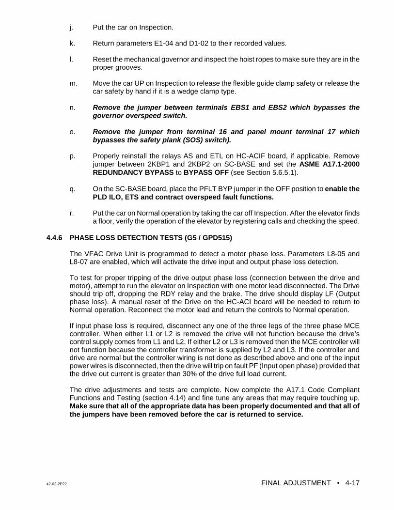
42-02-2P22 FINAL ADJUSTMENT • 4-17
j. Put the car on Inspection.
k. Return parameters E1-04 and D1-02 to their recorded values.
l. Reset the mechanical governor and inspect the hoist ropes to make sure they are in theproper grooves.
m. Move the car UP on Inspection to release the flexible guide clamp safety or release thecar safety by hand if it is a wedge clamp type.
n. Remove the jumper between terminals EBS1 and EBS2 which bypasses thegovernor overspeed switch.
o. Remove the jumper from terminal 16 and panel mount terminal 17 whichbypasses the safety plank (SOS) switch).
p. Properly reinstall the relays AS and ETL on HC-ACIF board, if applicable. Removejumper between 2KBP1 and 2KBP2 on SC-BASE and set the ASME A17.1-2000REDUNDANCY BYPASS to BYPASS OFF (see Section 5.6.5.1).
q. On the SC-BASE board, place the PFLT BYP jumper in the OFF position to enable thePLD ILO, ETS and contract overspeed fault functions.
r. Put the car on Normal operation by taking the car off Inspection. After the elevator findsa floor, verify the operation of the elevator by registering calls and checking the speed.
4.4.6 PHASE LOSS DETECTION TESTS (G5 / GPD515)
The VFAC Drive Unit is programmed to detect a motor phase loss. Parameters L8-05 andL8-07 are enabled, which will activate the drive input and output phase loss detection.
To test for proper tripping of the drive output phase loss (connection between the drive andmotor), attempt to run the elevator on Inspection with one motor lead disconnected. The Driveshould trip off, dropping the RDY relay and the brake. The drive should display LF (Outputphase loss). A manual reset of the Drive on the HC-ACI board will be needed to return toNormal operation. Reconnect the motor lead and return the controls to Normal operation.
If input phase loss is required, disconnect any one of the three legs of the three phase MCEcontroller. When either L1 or L2 is removed the drive will not function because the drive’scontrol supply comes from L1 and L2. If either L2 or L3 is removed then the MCE controller willnot function because the controller transformer is supplied by L2 and L3. If the controller anddrive are normal but the controller wiring is not done as described above and one of the inputpower wires is disconnected, then the drive will trip on fault PF (Input open phase) provided thatthe drive out current is greater than 30% of the drive full load current.
The drive adjustments and tests are complete. Now complete the A17.1 Code CompliantFunctions and Testing (section 4.14) and fine tune any areas that may require touching up.Make sure that all of the appropriate data has been properly documented and that all ofthe jumpers have been removed before the car is returned to service.
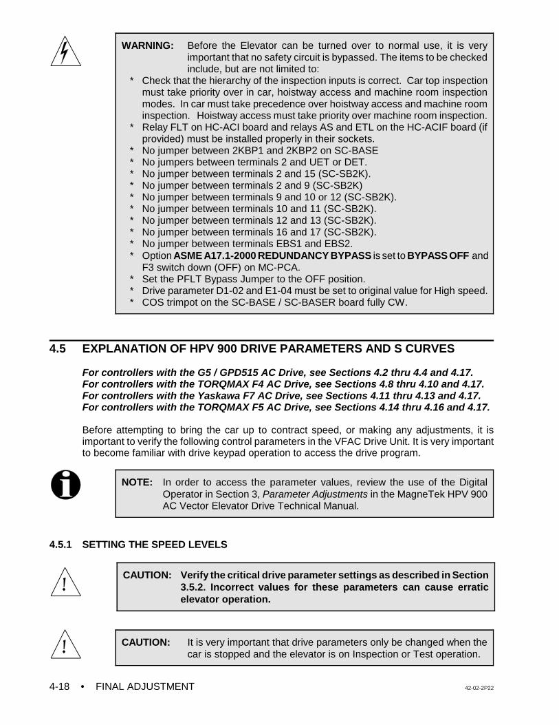
• FINAL ADJUSTMENT 42-02-2P224-18
WARNING: Before the Elevator can be turned over to normal use, it is veryimportant that no safety circuit is bypassed. The items to be checkedinclude, but are not limited to:
* Check that the hierarchy of the inspection inputs is correct. Car top inspectionmust take priority over in car, hoistway access and machine room inspectionmodes. In car must take precedence over hoistway access and machine roominspection. Hoistway access must take priority over machine room inspection.
* Relay FLT on HC-ACI board and relays AS and ETL on the HC-ACIF board (ifprovided) must be installed properly in their sockets.
* No jumper between 2KBP1 and 2KBP2 on SC-BASE * No jumpers between terminals 2 and UET or DET.* No jumper between terminals 2 and 15 (SC-SB2K).* No jumper between terminals 2 and 9 (SC-SB2K)* No jumper between terminals 9 and 10 or 12 (SC-SB2K).* No jumper between terminals 10 and 11 (SC-SB2K).* No jumper between terminals 12 and 13 (SC-SB2K).* No jumper between terminals 16 and 17 (SC-SB2K).* No jumper between terminals EBS1 and EBS2.* Option ASME A17.1-2000 REDUNDANCY BYPASS is set to BYPASS OFF and
F3 switch down (OFF) on MC-PCA. * Set the PFLT Bypass Jumper to the OFF position.* Drive parameter D1-02 and E1-04 must be set to original value for High speed.* COS trimpot on the SC-BASE / SC-BASER board fully CW.
NOTE: In order to access the parameter values, review the use of the DigitalOperator in Section 3, Parameter Adjustments in the MagneTek HPV 900AC Vector Elevator Drive Technical Manual.
CAUTION: Verify the critical drive parameter settings as described in Section3.5.2. Incorrect values for these parameters can cause erraticelevator operation.
CAUTION: It is very important that drive parameters only be changed when thecar is stopped and the elevator is on Inspection or Test operation.
4.5 EXPLANATION OF HPV 900 DRIVE PARAMETERS AND S CURVES
For controllers with the G5 / GPD515 AC Drive, see Sections 4.2 thru 4.4 and 4.17.For controllers with the TORQMAX F4 AC Drive, see Sections 4.8 thru 4.10 and 4.17.For controllers with the Yaskawa F7 AC Drive, see Sections 4.11 thru 4.13 and 4.17.For controllers with the TORQMAX F5 AC Drive, see Sections 4.14 thru 4.16 and 4.17.
Before attempting to bring the car up to contract speed, or making any adjustments, it isimportant to verify the following control parameters in the VFAC Drive Unit. It is very importantto become familiar with drive keypad operation to access the drive program.
4.5.1 SETTING THE SPEED LEVELS
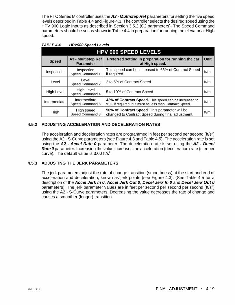
42-02-2P22 FINAL ADJUSTMENT • 4-19
The PTC Series M controller uses the A3 - Multistep Ref parameters for setting the five speedlevels described in Table 4.4 and Figure 4.3. The controller selects the desired speed using theHPV 900 Logic Inputs as described in Section 3.5.2 (C2 parameters). The Speed Commandparameters should be set as shown in Table 4.4 in preparation for running the elevator at Highspeed.
TABLE 4.4 HPV900 Speed Levels
HPV 900 SPEED LEVELS
Speed A3 - Multistep RefParameter
Preferred setting in preparation for running the carat High speed.
Unit
Inspection InspectionSpeed Command 1
This speed can be increased to 66% of Contract Speedif required. ft/m
Level LevelSpeed Command 2
2 to 5% of Contract Speed ft/m
High Level High LevelSpeed Command 4
5 to 10% of Contract Speed ft/m
Intermediate IntermediateSpeed Command 6
42% of Contract Speed. This speed can be increased to91% if required, but must be less than Contract Speed.
ft/m
High High speedSpeed Command 8
50% of Contract Speed. This parameter will bechanged to Contract Speed during final adjustment.
ft/m
4.5.2 ADJUSTING ACCELERATION AND DECELERATION RATES
The acceleration and deceleration rates are programmed in feet per second per second (ft/s2)using the A2 - S-Curve parameters (see Figure 4.3 and Table 4.5). The acceleration rate is setusing the A2 - Accel Rate 0 parameter. The deceleration rate is set using the A2 - DecelRate 0 parameter. Increasing the value increases the acceleration (deceleration) rate (steepercurve). The default value is 3.00 ft/s2.
4.5.3 ADJUSTING THE JERK PARAMETERS
The jerk parameters adjust the rate of change transition (smoothness) at the start and end ofacceleration and deceleration, known as jerk points (see Figure 4.3). (See Table 4.5 for adescription of the Accel Jerk In 0, Accel Jerk Out 0, Decel Jerk ln 0 and Decel Jerk Out 0parameters). The jerk parameter values are in feet per second per second per second (ft/s3)using the A2 - S-Curve parameters. Decreasing the value decreases the rate of change andcauses a smoother (longer) transition.
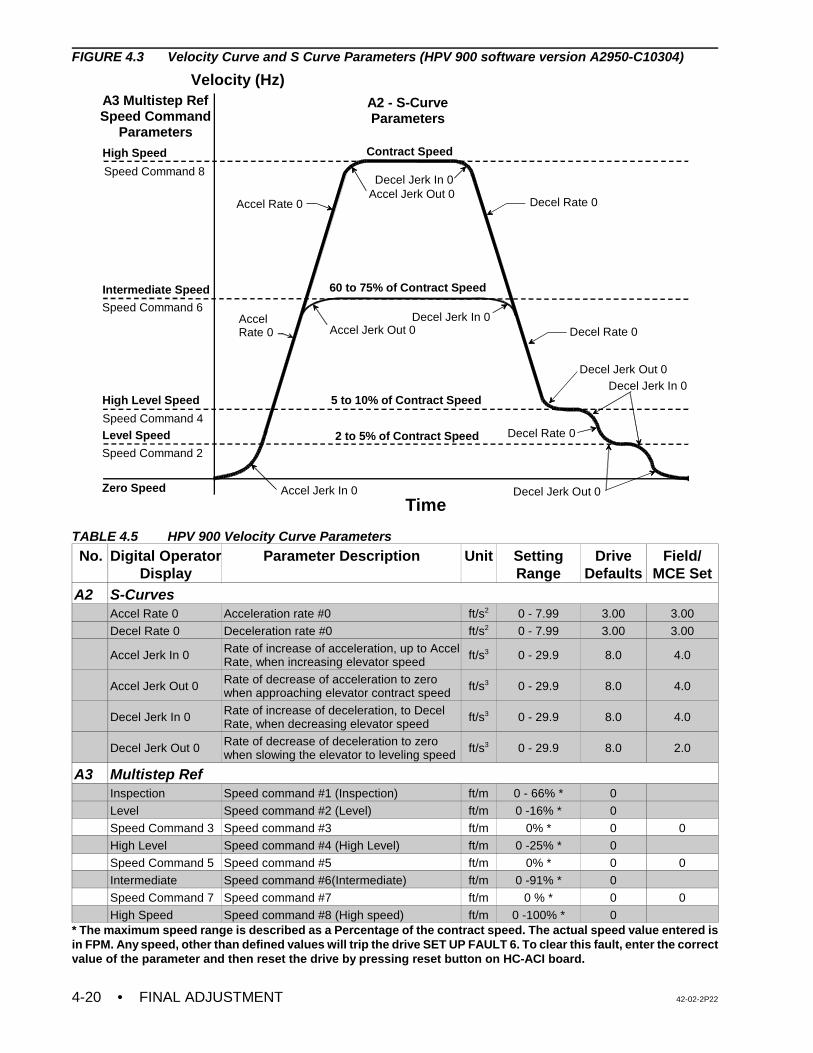
• FINAL ADJUSTMENT 42-02-2P224-20
Velocity (Hz)
TimeZero Speed
Level Speed
High Level Speed
Intermediate Speed
High Speed
Accel Jerk In 0
Accel Rate 0 Decel Rate 0
Decel Jerk Out 0
Accel Jerk Out 0
Decel Jerk In 0
Decel Jerk In 0
Decel Jerk In 0
Contract Speed
5 to 10% of Contract Speed
2 to 5% of Contract Speed
A3 Multistep RefSpeed Command
Parameters
A2 - S-CurveParameters
Decel Rate 0
Decel Rate 0Accel Rate 0
60 to 75% of Contract Speed
Speed Command 8
Speed Command 6
Speed Command 4
Speed Command 2
Accel Jerk Out 0
Decel Jerk Out 0
FIGURE 4.3 Velocity Curve and S Curve Parameters (HPV 900 software version A2950-C10304)
TABLE 4.5 HPV 900 Velocity Curve Parameters
No. Digital OperatorDisplay
Parameter Description Unit SettingRange
DriveDefaults
Field/MCE Set
A2 S-CurvesAccel Rate 0 Acceleration rate #0 ft/s2 0 - 7.99 3.00 3.00
Decel Rate 0 Deceleration rate #0 ft/s2 0 - 7.99 3.00 3.00
Accel Jerk In 0 Rate of increase of acceleration, up to AccelRate, when increasing elevator speed ft/s3 0 - 29.9 8.0 4.0
Accel Jerk Out 0 Rate of decrease of acceleration to zerowhen approaching elevator contract speed ft/s3 0 - 29.9 8.0 4.0
Decel Jerk In 0 Rate of increase of deceleration, to DecelRate, when decreasing elevator speed ft/s3 0 - 29.9 8.0 4.0
Decel Jerk Out 0 Rate of decrease of deceleration to zerowhen slowing the elevator to leveling speed ft/s3 0 - 29.9 8.0 2.0
A3 Multistep RefInspection Speed command #1 (Inspection) ft/m 0 - 66% * 0
Level Speed command #2 (Level) ft/m 0 -16% * 0
Speed Command 3 Speed command #3 ft/m 0% * 0 0
High Level Speed command #4 (High Level) ft/m 0 -25% * 0
Speed Command 5 Speed command #5 ft/m 0% * 0 0
Intermediate Speed command #6(Intermediate) ft/m 0 -91% * 0
Speed Command 7 Speed command #7 ft/m 0 % * 0 0
High Speed Speed command #8 (High speed) ft/m 0 -100% * 0* The maximum speed range is described as a Percentage of the contract speed. The actual speed value entered isin FPM. Any speed, other than defined values will trip the drive SET UP FAULT 6. To clear this fault, enter the correctvalue of the parameter and then reset the drive by pressing reset button on HC-ACI board.
42-02-2P22 FINAL ADJUSTMENT • 4-21
The output response of the drive can be seen on an oscilloscope, when the car is running, bylooking at the voltage between terminals 35 (Output Frequency) and 34 (Com) on the HPV 900drive. The input can be seen at terminal 33 (Speed Reference) and 34 (Com). The outputsignal is 0 -10VDC.
The High Level speed (A3 - Speed Command 4), Level speed (A3 - Speed Command 2),Deceleration rate (A2 - Decel Rate 0) and Deceleration Jerk (A2 - Decel Jerk In 0, A2 - DecelJerk Out 0) parameters should be adjusted for correct approach to the floor.
The Acceleration rate (A2 - Accel Rate 0), and the Acceleration Jerk (A2 - Accel Jerk In 0, A2 -Accel Jerk Out 0) parameters can be adjusted for smooth starting and transition to High speed.This will be addressed in the final adjustment section.
4.6 FINAL ADJUSTMENTS (HPV 900)
For controllers with the G5 / GPD515 AC Drive, see Sections 4.2 thru 4.4 and 4.17.For controllers with the TORQMAX F4 AC Drive, see Sections 4.8 thru 4.10 and 4.17.For controllers with the Yaskawa F7 AC Drive, see Sections 4.11 thru 4.13 and 4.17.For controllers with the TORQMAX F5 AC Drive, see Sections 4.14 thru 4.16 and 4.17.
4.6.1 FINAL PREPARATION FOR RUNNING ON AUTOMATIC OPERATION (HPV 900)
a. Temporarily take the car off of Inspection operation. If the LED display does not showTEST MODE, see what message is being displayed and correct the problem. Forexample, if the indicators show that the car is on Fire Service Phase 1, a jumper mustbe connected between terminal 2 on the back plate and terminal 38 on the SC-SB2Kboard in order to run the car on Normal Operation. Remove the jumper once the FireService input is brought into the controller. Place the car back on Inspection.
b. Move the car to the bottom terminal landing. Check to see if the DZ relay is picked. Ifnot, move the car on Inspection to place it in the Door Zone.
4.6.2 SWITCHING TO AUTOMATIC OPERATION (HPV 900)
Place the Relay Panel Inspection switch in the OFF position. If the car is not at a landing it willmove to a landing. If the car is at a landing but not in the door zone, relays L and either LU1/2or LD1/2 should pick and the car should perform a relevel. If the relevel is not successful, checkthe following:
C If the brake picks and the car is trying to level but is not able to, it may be necessary toadjust the Level Speed parameter (A3 - Speed Command 2) on the HPV 900 AC Driveto get the car to move.
C If relays L and LD1/2 are picked, but the brake and other relays are not, the downdirection limit switch may be preventing the leveling down operation.
C If the car is trying to level, it will not leave the landing for a call until the leveling iscomplete. Move the limit switch if necessary.
The Status Indicator lights should now display the indication for Independent Service operation.At this time the Position Indicator should match the actual car location. Note that all of thePosition Indicators and direction arrows are conveniently displayed on the controller. All thecalls are also displayed on the controller.
• FINAL ADJUSTMENT 42-02-2P224-22
NOTE: It is very important that the drive parameters only be changed when the caris stopped and the elevator is on Inspection or Test operation so that thereis no demand.
NOTE: Drive gain adjustments - The default values for the gain parameters (A-1Response, A1-Inertia and A1-Inner Loop Xover) are sufficient to run the caron High speed. However, for optimum performance and to help inachieving Contract Speed, adaptive tuning of the drive as described inSection 4.6.5 is strongly recommended.
4.6.3 BRAKE ADJUSTMENT FOR 125% LOAD (HPV 900)
Put the car on Inspection at the bottom landing. Put 2/3 of a contract load in the car. Beginadding weights in 50 or 100 pound increments and move the car up and down on Inspectioneach time. Adjust the brake tension to stop and hold 125% of a contract load by tripping a stopswitch open while running down on Inspection. Hold the DOWN button in while tripping openthe stop switch (preferably on the Inspection station). KEEP THE CAR NEAR THE BOTTOMAS IT IS LIKELY TO SLIDE THROUGH THE BRAKE ONTO THE BUFFERS. If the VFAC DriveUnit trips off when the car is going down, but not while it is going up, refer to the manual for theVFAC Drive Unit and look up the failure indication on the Drive display. If it is the display for anover-voltage fault, there may be a problem in the regeneration (or braking) resistors, thebraking module (if one is provided), or in the fuses that may be in series with the wires to thebraking resistors. If this problem cannot be solved, call MCE Technical Support. Remove alltest weights from the car.
4.6.4 BRINGING THE CAR UP TO HIGH SPEED (HPV 900)
a. Verify that all the steps described in Sections 4.1 and 4.5 regarding the adjustmentsand specifically the drive parameters are complete.
b. Register a car call one floor above the car. The High speed relay (H) should pick andthe drive keypad display should read 50% of Contract Speed as the car attempts tostart. If the car runs normally, commence multi-floor runs and slowly increase Highspeed by increasing the A3 - Speed Command 8 parameter until Contract Speed isachieved. If there is a problem reaching Contract Speed, see the following note.
c. At the slowdown distance from the next floor the Position Indicator will step. Afterstepping occurs, High speed is dropped and the car should rapidly decelerate to HighLevel speed. Reduce the High Level speed (A3 - Speed Command 4) so that the carruns at about 10 - 20 fpm or at a reasonable speed (use your personal judgment). Sixinches before the floor at which the car is to stop, High Level speed is dropped and thecar speed should decelerate to Level speed. The Level speed can be adjusted usingthe A3 - Speed Command 2 parameter so that the car levels into the floor and stops.Level speed should be 5 - 7 fpm, or a reasonable leveling speed (use personal judge-ment). If the car relevels frequently once Level speed is adjusted satisfactorily, spreadapart the LU and LD sensors or switches in the landing system to provide enough DeadZone (usually 1/4" to 3/8" is sufficient).
d. Adjust the SPD (Speed Pick Delay) trimpot by first turning it far enough clockwise sothat the empty car rolls back in the direction of the counterweight (if it can). Then adjustSPD so that the brake is fully picked just as the motor first moves. The goal is to delay
42-02-2P22 FINAL ADJUSTMENT • 4-23
NOTE: To observe the commanded speed and the drive output with anoscilloscope or a chart recorder, monitor drive terminal 33 and 35 withrespect to 34. Take all necessary precautions while measuring the voltagesignals.
CAUTION: Most oscilloscopes have a grounding pin on their power plug. Werecommend defeating the grounding pin with one of the commonlyavailable ground isolation adapter plugs so that the case of theoscilloscope is not at ground potential, but at whatever potential thenegative probe lead is connected to. TREAT THE CASE OF THEOSCILLOSCOPE AS A LETHAL SHOCK HAZARD, DEPENDINGON WHERE THE NEGATIVE PROBE IS CONNECTED. Thisrecommendation is being made because the ground potential on thegrounding pin of the power outlet may not be the same as thecontroller cabinet ground. If it is not, substantial ground loop currentmay flow between the negative probe and the power plug groundingpin which can ruin the oscilloscope
long enough to avoid moving the motor before the brake is fully lifted, but not so longas to allow the car to roll back.
e. Run the car again and verify that the car will start, accelerate, decelerate and run atHigh Level and Level speeds into the floor and stop. Place calls for all of the landings.Verify that all of the calls work. Verify the operation and placement of all vanes ormagnets and vane or magnet switches and verify that the car steps the PositionIndicators correctly. The slowdown distance for the elevator is measured from the pointwhere the STU sensor (or STD sensor, if going down) is activated by a metal vane ormagnetic strip to the position where the car is stopped at the floor with the DZ sensorcentered on the leveling target with LU or LD sensors not engaged.
This slowdown distance was chosen to give a reasonable deceleration rate. Continueto make two-floor runs and slowly increase High speed until Contract Speed is reached.It may be necessary to adjust the Deceleration rate (A2 - Decel Rate 0) andDeceleration Jerk (A2 - Decel Jerk In 0, A2 - Decel Jerk Out 0) parameters to get thecar to approach the floor correctly as the car speed increases. Adjust the Accelerationrate (A2 - Accel Rate 0) and Acceleration Jerk (A2 - Accel Jerk In 0, A2 - Accel Jerk Out0) parameters until the desired acceleration rate is achieved. Several runs may berequired to obtain optimum acceleration. The acceleration rate should be about thesame as the deceleration rate.
f. To achieve a proper start, without rollback (or snapping away from the floor), a variabledelay in the application of the speed signal has been provided by adjusting trimpot SPD(Speed Pick Delay). Trimpot SPD must be adjusted to let the brake just clear the brakedrum before attempting to accelerate the car. Do this with an empty car. The correctsetting will be obvious by watching the Drive sheave. This was adjusted previously;however, check trimpot SPD again and make adjustments if necessary. The responseof the car can be monitored using an oscilloscope by measuring the voltage on the driveterminals 33 and 35 with respect to 34. These signals are 0 -10 and 0 - 8 voltsrespectively. Terminal 33 is programmed for the drive input speed reference andterminal 35 is programmed for the drive output frequency.
• FINAL ADJUSTMENT 42-02-2P224-24
NOTE: After performing the test in Section 5.5.1.2 (TUNING MOTOR NO LOADCURRENT), the motor torque reading may not equal ±15%. If so, proceedto the next step in the test.
g. The car should be running well now, except possibly for the final stop. Since the speedreference goes to zero when the car stops, the VFAC Drive Unit will cause the machineto stop electrically. Enough delay in the setting of the brake (BDD) will have to beprovided to allow the sheave to stop turning before setting the brake firmly on the brakedrum.
When the elevator slows down to leveling speed and travels to door zone, the speedcommand will drop to zero before the brake drops. This is adjustable by the BDD (BrakeDrop Delay) trimpot. The idea is to hold the brake up long enough to allow the motorto be stopped electrically and then drop the brake immediately the instant the motor hasstopped.
If there is too long of a delay before dropping the brake, the control system will releaseits control of the motor and the motor will drift briefly in the direction of the load beforethe brake is forced to drop by the PT relay. The BDD trimpot controls the dropping ofthe brake through the BE relay. Move the LU and LD sensors or switches closertogether (or further apart) so the car stops at the same location, up or down. Then movethe floor (leveling) magnet strips or vanes so the car stops accurately at each floor.
h. The adjustment is almost complete. The acceleration rate parameter setting should beat least as great as the deceleration rate parameter, but it should not be so high that itsubstantially exceeds the value of the deceleration rate parameter. Excessiveacceleration may cause the VFAC Drive circuits to saturate and thereby lose control ofthe car. Ideally, the slope of the acceleration in volts per second should be equal to theslope of the deceleration. Note the present value of the A2 - Decel Rate 0 parameter.Increase the value of A2 - Decel Rate 0 and run the car. Continue to increase the valueof A2 - Decel Rate 0 until the car overshoots the floor, requiring a relevel operation.Observe the response of the car to verify a stable releveling operation. Return the valueof the A2 - Decel Rate 0 parameter to its original value so that the approach to the flooris the same as before. After the car stops, check the empty car releveling operation byplacing a jumper between terminals 18 and 26 to cause an up level after which the carwill stop due to picking the LD (Down Level) switch. Remove the jumper from terminals18 and 26 and the car will level down against the counterweight. Make sure that it doesnot stall. If the car stalls then you might have to increase the leveling speed.
4.6.5 ADAPTIVE TUNING (HPV 900)
To tune this drive for optimum performance, follow the procedure in Section 5.5 in theMagneTek HPV 900 AC Vector Drive Technical Manual. Adaptive tuning automatically adjuststhe no load current, slip, RPM (to run at Contract speed) and inertia (tunes up the speedregulator).
Note: In the adaptive tuning procedure, to achieve 70% of contract speed, adjust onlythe High Speed parameter to 70% of contract speed (A3 - Multistep Ref).
42-02-2P22 FINAL ADJUSTMENT • 4-25
4.6.6 LOAD TESTING (HPV 900)
a. Begin adding test weights to the car in 100 or 200 pound increments all the way up tothe rated load. Observe the VFAC Drive Unit current on its display and check to see ifthere is an OC (Over Current) error indication as the car accelerates to full speed. If so,this indicates that the VFAC unit is being pushed close to its limits and may require oneor more of the following actions:
1. The requested acceleration rate may be excessive. Try reducing theacceleration rate by decreasing the A2 - Accel Rate 0 parameter. The lower therate of acceleration, the lower the current demand.
2. A more gradual transition from acceleration to high speed may be made bydecreasing the A2 - Accel Jerk Out 0 parameter.
3. The motor may be underrated. It may be possible to get excellent results if thespeed is reduced slightly.
4. The elevator may be improperly counter weighted. This possibility should bethoroughly investigated.
5. Make a copy of the table in Appendix C, Quick Reference for MagneTek HPV900 Drive Parameters and use the digital operator on the HPV 900 Drive Unitto look up and write down every parameter value as programmed in the unit.Use this as a reference when calling MCE to review the data.
b. If there is a full load in the car and there is trouble slowing in the down direction, or ifthe VFAC Drive Unit is tripping off and there is an OV (over-voltage) fault displayed, itmay mean that there is a problem with the regeneration (braking) resistors and/or thebraking unit (if supplied separately). Check for DC bus voltage. There are two methodsto check the DC bus voltage as described below:
1. Through the drive keypad display: When the drive is in Operation mode, accessthe D2 Power Data - DC bus voltage parameter. You can then run the elevatorand watch the voltage reading.
2. Actual measurement of voltage: Use extreme care when measuring the DCvoltage across the drive power terminals (-) and (+ 3 or +4) under the aboveconditions.
If the bus voltage is 325 VDC (for a 230 VAC motor) or 650 VDC (for 460 VAC motor), and ifthere is no voltage measured across the braking resistors while the car is slowing with a fullload going down or empty car up, there may be a wiring problem, or a defective braking unit(if provided). Be sure to investigate this thoroughly. These resistors perform the task ofregulating car speed during a full load down or empty car up run (regeneration).
• FINAL ADJUSTMENT 42-02-2P224-26
WARNING: The following tests should be performed only by qualified elevatorpersonnel skilled in final adjustment and inspections.
4.7 FINAL ELEVATOR INSPECTION PROCEDURE (HPV 900)
For controllers with the G5 / GPD515 AC Drive, see Sections 4.2 thru 4.4 and 4.17.For controllers with the TORQMAX F4 AC Drive, see Sections 4.8 thru 4.10 and 4.17.For controllers with the Yaskawa F7 AC Drive, see Sections 4.11 thru 4.13 and 4.17.For controllers with the TORQMAX F5 AC Drive, see Sections 4.14 thru 4.16 and 4.17.
4.7.1 INSPECTION LEVELING OVER SPEED TEST (HPV 900)
Note: Before performing tests 4.7.1 and 4.7.3, please remove the jumper between pins labeled2KBP1 and 2KBP2 on the SC-BASE board. Also rotate trimpots ILO, ETS and COS fully CW.
The SC-BASE board is equipped with an independent low speed monitoring system which canshut down the system if the car runs faster than a trimpot adjustable preset speed on Car TopInspection, Hoistway Access or Leveling operation. The monitoring system is active when theLeveling (LU1/LU2, LD1/LD2) relays are picked or when the Access/Inspection relay (IN1) isdropped out. The trimpot is labeled ILO (Inspection Leveling Overspeed) and is located on theSC-BASE board. The circuit looks at pulses coming from the speed sensor, sensing a magneton the motor shaft or brake drum, etc. Calibrate this circuit as follows:
a. Put the car on Inspection operation by placing the MACHINE ROOM INSPECTIONTRANSFER switch on the SC-SB2K Main Safety Relay board in the INSP position.
b. Run the car on Inspection (up or down) and record the actual values for parameter A3-Speed Command 1 ________. A3 - speed command 1 must be returned to the originalvalue when this test is complete. Now, run the car on Inspection and adjust the INspeed (A3) until the car is running at the desired tripping speed for ILO.
c. Next, adjust the ILO trimpot CCW until the ILO1/ILO2 indicators turn on. The car shouldcome to an immediate stop and the MC-PCA-OA2K LCD display should read “ILOFault”. The ILO fault should self reset in a moment.
d. Reduce inspection speed with A3 - speed command 1. Run the car on Inspection andincrease the inspection speed by increasing A3 -speed command 1 to show that thislow speed safety monitor circuit will trip at no higher than 150 fpm (or no higher than thesetting you calibrated in (b)). Check this in both directions. The overspeed monitor isnow calibrated for less than 150 fpm for Access, Inspection and Leveling. Returnparameter A3 -speed command 1 to the value recorded in Step (b).
4.7.2 TERMINAL SLOWDOWN LIMIT SWITCHES (HPV 900)
Make sure that the terminal slowdown limit switches are working properly by doing thefollowing:
a. Place the TEST/NORMAL switch on the SC-SB2K board in the TEST position.
b. Disconnect and label the wires from terminals 71 (STU) and 72 (STD) on the SC-SB2Kboard.
42-02-2P22 FINAL ADJUSTMENT • 4-27
c. Register calls for the terminal landings (top and bottom) from the controller. The carshould make a normal slowdown at both terminal landings except that there may be aslight relevel, which is okay. If the car goes more than an inch past the floor, move theslowdown limit until the approach is normal.
d. Reconnect the wires to terminals 71(STU) and 72 (STD) on the SC-SB2K board andreturn theTEST/NORMAL switch to the NORMAL position.
4.7.3 EMERGENCY TERMINAL LIMIT SWITCH MONITOR (HPV 900)
All jobs under the requirements of ANSI A17.1 -2000 Articles 2.25.4.1. or 2.25.4.2 must havea means to insure that the car speed is below contract speed after opening the associatedETS limit switches. The emergency terminal limit switch monitor performs this function.
The SC-BASE board carries out ETS monitoring functions via a speed senor that monitors amagnet installed on the motor shaft or brake drum as described in Section 2.2.3, Installing andWiring the Speed Sensor.
a. Make sure that shielded phone cable from the sensor to the SC-BASE board is securelyseated in the connectors at both ends and is also enclosed in conduit.
b. Check that the ETS trimpot, located on the SC-BASE, is fully CW.
c. Record the value of the H speed parameter (A3 - speed command 8) Then on a multi-floor run, adjust the speed of the car to 90% of the contract speed by adjusting theH speed (A3 - speed command 8) parameter.
d. Remove both the Up Emergency and Terminal Limit Switch wires where they connectto the controller at terminals UETS1 and UETS2 on the SC-BASE board. Start the carat the bottom of the hoistway and while running the car in the up direction, slowly turnthe ETS trimpot CCW until the ETS indicator turns ON and the car stops. A faultmessage should be displayed on the MC-PCA board’s LCD display.
e. Press the fault reset push button on the SC-SB2K board to reset the fault.
f. Repeat (d) and (e) in the down direction with the wires from the DETS terminalsremoved. When the calibration is complete, reconnect the wires removed from theUETS and DETS terminals and return the H speed parameter (A3 - speed command8) to its original value.
g. Verify the calibration by turning OFF the inspection transfer switch. Place a call, andwith the car running at contract speed, remove the field wires from the UETS1 andUETS2 terminals on the SC-BASE board. The car must execute an emergencyslowdown. To restore normal operation, replace the wires and press the Fault Resetpushbutton on the SC-SB2K board. Repeat for terminals DETS1 and DETS2.
4.7.4 CONTRACT SPEED BUFFER TEST (HPV 900):
4.7.4.1. COUNTER WEIGHT BUFFER TEST WITH EMPTY CAR GOING UP
a. On the SC-BASE board, install the jumper between pins 2KBP1 and 2KBP2. Also setthe ASME A17.1-2000 REDUNDANCY BYPASS to BYPASS ON (see section 5.6.5.1).
b. On the SC-BASE board, place the PFLT Bypass jumper in the ON position to bypassthe PLD ILO, ETS and contract overspeed fault functions.
c. Disconnect the Step Up (STU) input by removing the wire from terminal 72 on theSC-SB2K board. Tape the wire to prevent shorting.
• FINAL ADJUSTMENT 42-02-2P224-28
d. Bypass the Emergency Terminal Up Limits, if provided, by placing jumpers betweenterminals 2 and UETS1 / UETS2 on the SC-BASE board.
e. Bypass the Up terminal slowdown and Up Normal Limit by placing jumpersbetween terminals 9 and 10 and terminals 10 and 11 on the SC-SB2K board.
f. Register a car call for the top terminal landing from the controller. The counterweightwill strike the buffer.
g. Put the elevator on Inspection and pick the down direction to move the car.
h. Remove the jumpers between terminals 9 and 10, and terminals 10 and 11 andreconnect the wire to terminal 72 on the SC-SB2K board.
i. On the SC-BASE board, place the PFLT Bypass jumper in the OFF position to enablethe PLD ILO, ETS and contract overspeed fault functions.
j. On the SC-BASE board, remove the jumper between pins 2KBP1 and 2KBP2. Also setthe ASME A17.1-2000 REDUNDANCY BYPASS to BYPASS OFF (see Section5.6.5.1).
4.7.4.2 CAR BUFFER TEST WITH A FULL LOAD GOING DOWN
a. On the SC-BASE board, install the jumper between pins 2KBP1 and 2KBP2. Also setthe ASME A17.1-2000 REDUNDANCY BYPASS to BYPASS ON (see section 5.6.5.1).
b. On the SC-BASE board, place the PFLT Bypass jumper in the ON position to bypassthe PLD ILO, ETS and contract overspeed fault functions.
c. Disconnect the Step Down (STD) input by removing the wire from terminal 71 on theSC-SB2K board and tape the wire to prevent shorting.
d. Bypass the Emergency Terminal Down Limits, if provided, by placing jumpersbetween terminals 2 and DETS1 / DETS2 on the SC-BASE board.
e. Bypass the Down terminal slowdown and Down Normal Limit by placing jumpersbetween terminals 9 and 12 and terminals 12 and 13 on the SC-SB2K board.
f. Position the elevator several floors above the bottom landing with a full load in the car.Then register a car call for the bottom landing. The car will strike the buffer.
g. Put the elevator on Inspection and pick the up direction to move the car.
h. On the SC-BASE board, place the PFLT Bypass jumper in the OFF position to enablethe PLD ILO, ETS and contract overspeed fault functions.
i. Remove the jumpers between terminals 9 and 12 and terminals 12 and 13 andreconnect the wire to terminal 71 on the SC-SB2K board.
j. On the SC-BASE board, remove the jumper between pins 2KBP1 and 2KBP2. Also setthe ASME A17.1-2000 REDUNDANCY BYPASS to BYPASS OFF (see Section5.6.5.1). Remove all of the jumpers installed in this section.
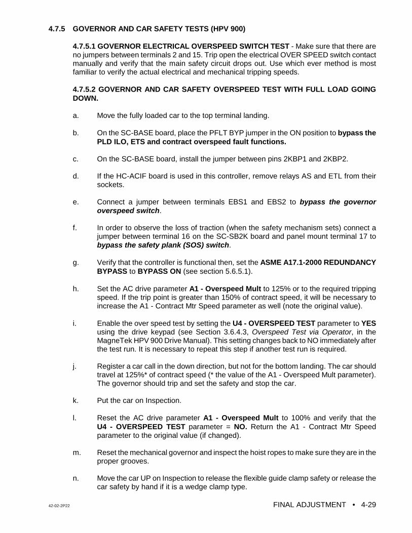
42-02-2P22 FINAL ADJUSTMENT • 4-29
4.7.5 GOVERNOR AND CAR SAFETY TESTS (HPV 900)
4.7.5.1 GOVERNOR ELECTRICAL OVERSPEED SWITCH TEST - Make sure that there areno jumpers between terminals 2 and 15. Trip open the electrical OVER SPEED switch contactmanually and verify that the main safety circuit drops out. Use which ever method is mostfamiliar to verify the actual electrical and mechanical tripping speeds.
4.7.5.2 GOVERNOR AND CAR SAFETY OVERSPEED TEST WITH FULL LOAD GOINGDOWN.
a. Move the fully loaded car to the top terminal landing.
b. On the SC-BASE board, place the PFLT BYP jumper in the ON position to bypass thePLD ILO, ETS and contract overspeed fault functions.
c. On the SC-BASE board, install the jumper between pins 2KBP1 and 2KBP2.
d. If the HC-ACIF board is used in this controller, remove relays AS and ETL from theirsockets.
e. Connect a jumper between terminals EBS1 and EBS2 to bypass the governoroverspeed switch.
f. In order to observe the loss of traction (when the safety mechanism sets) connect a
jumper between terminal 16 on the SC-SB2K board and panel mount terminal 17 tobypass the safety plank (SOS) switch.
g. Verify that the controller is functional then, set the ASME A17.1-2000 REDUNDANCYBYPASS to BYPASS ON (see section 5.6.5.1).
h. Set the AC drive parameter A1 - Overspeed Mult to 125% or to the required trippingspeed. If the trip point is greater than 150% of contract speed, it will be necessary toincrease the A1 - Contract Mtr Speed parameter as well (note the original value).
i. Enable the over speed test by setting the U4 - OVERSPEED TEST parameter to YESusing the drive keypad (see Section 3.6.4.3, Overspeed Test via Operator, in theMagneTek HPV 900 Drive Manual). This setting changes back to NO immediately afterthe test run. It is necessary to repeat this step if another test run is required.
j. Register a car call in the down direction, but not for the bottom landing. The car shouldtravel at 125%* of contract speed (* the value of the A1 - Overspeed Mult parameter).The governor should trip and set the safety and stop the car.
k. Put the car on Inspection.
l. Reset the AC drive parameter A1 - Overspeed Mult to 100% and verify that theU4 - OVERSPEED TEST parameter = NO. Return the A1 - Contract Mtr Speedparameter to the original value (if changed).
m. Reset the mechanical governor and inspect the hoist ropes to make sure they are in theproper grooves.
n. Move the car UP on Inspection to release the flexible guide clamp safety or release thecar safety by hand if it is a wedge clamp type.
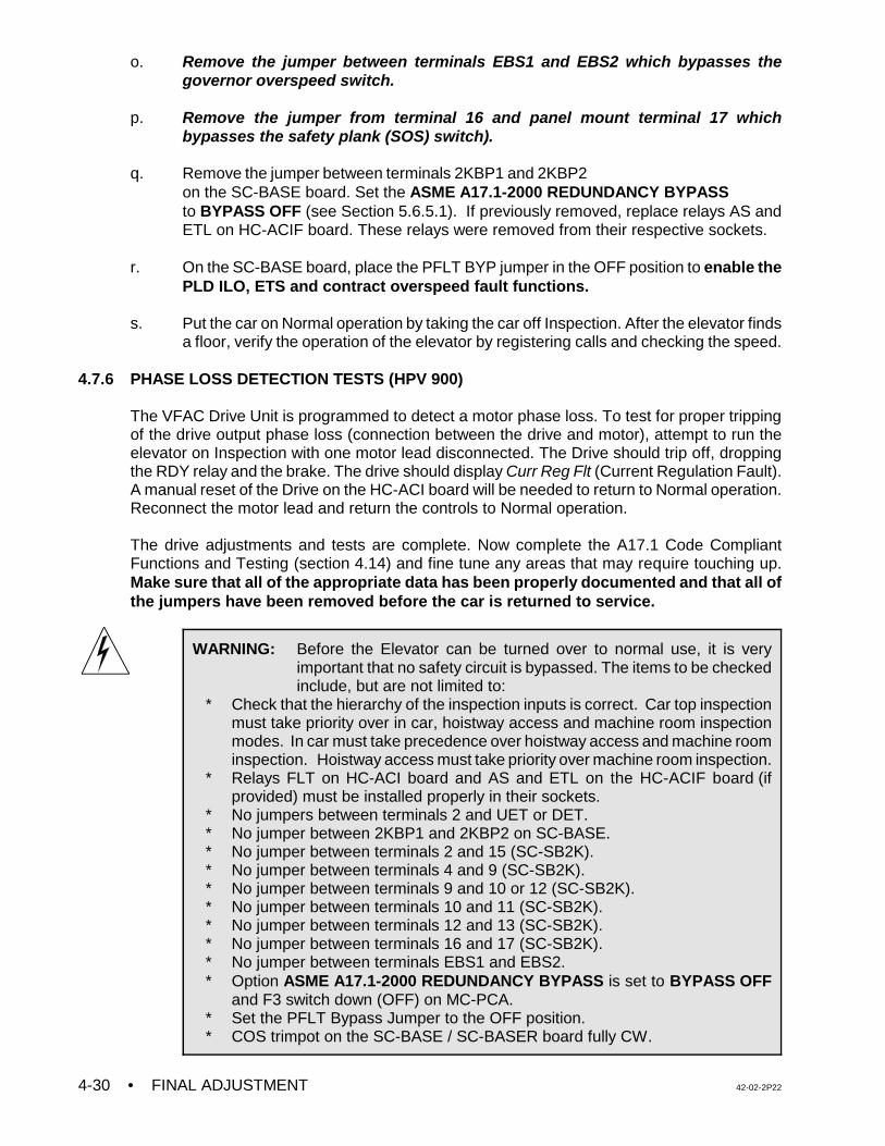
• FINAL ADJUSTMENT 42-02-2P224-30
WARNING: Before the Elevator can be turned over to normal use, it is veryimportant that no safety circuit is bypassed. The items to be checkedinclude, but are not limited to:
* Check that the hierarchy of the inspection inputs is correct. Car top inspectionmust take priority over in car, hoistway access and machine room inspectionmodes. In car must take precedence over hoistway access and machine roominspection. Hoistway access must take priority over machine room inspection.
* Relays FLT on HC-ACI board and AS and ETL on the HC-ACIF board (ifprovided) must be installed properly in their sockets.
* No jumpers between terminals 2 and UET or DET.* No jumper between 2KBP1 and 2KBP2 on SC-BASE.* No jumper between terminals 2 and 15 (SC-SB2K).* No jumper between terminals 4 and 9 (SC-SB2K).* No jumper between terminals 9 and 10 or 12 (SC-SB2K).* No jumper between terminals 10 and 11 (SC-SB2K).* No jumper between terminals 12 and 13 (SC-SB2K).* No jumper between terminals 16 and 17 (SC-SB2K).* No jumper between terminals EBS1 and EBS2.* Option ASME A17.1-2000 REDUNDANCY BYPASS is set to BYPASS OFF
and F3 switch down (OFF) on MC-PCA. * Set the PFLT Bypass Jumper to the OFF position.* COS trimpot on the SC-BASE / SC-BASER board fully CW.
o. Remove the jumper between terminals EBS1 and EBS2 which bypasses thegovernor overspeed switch.
p. Remove the jumper from terminal 16 and panel mount terminal 17 whichbypasses the safety plank (SOS) switch).
q. Remove the jumper between terminals 2KBP1 and 2KBP2 on the SC-BASE board. Set the ASME A17.1-2000 REDUNDANCY BYPASSto BYPASS OFF (see Section 5.6.5.1). If previously removed, replace relays AS andETL on HC-ACIF board. These relays were removed from their respective sockets.
r. On the SC-BASE board, place the PFLT BYP jumper in the OFF position to enable thePLD ILO, ETS and contract overspeed fault functions.
s. Put the car on Normal operation by taking the car off Inspection. After the elevator findsa floor, verify the operation of the elevator by registering calls and checking the speed.
4.7.6 PHASE LOSS DETECTION TESTS (HPV 900)
The VFAC Drive Unit is programmed to detect a motor phase loss. To test for proper trippingof the drive output phase loss (connection between the drive and motor), attempt to run theelevator on Inspection with one motor lead disconnected. The Drive should trip off, droppingthe RDY relay and the brake. The drive should display Curr Reg Flt (Current Regulation Fault).A manual reset of the Drive on the HC-ACI board will be needed to return to Normal operation.Reconnect the motor lead and return the controls to Normal operation.
The drive adjustments and tests are complete. Now complete the A17.1 Code CompliantFunctions and Testing (section 4.14) and fine tune any areas that may require touching up.Make sure that all of the appropriate data has been properly documented and that all ofthe jumpers have been removed before the car is returned to service.
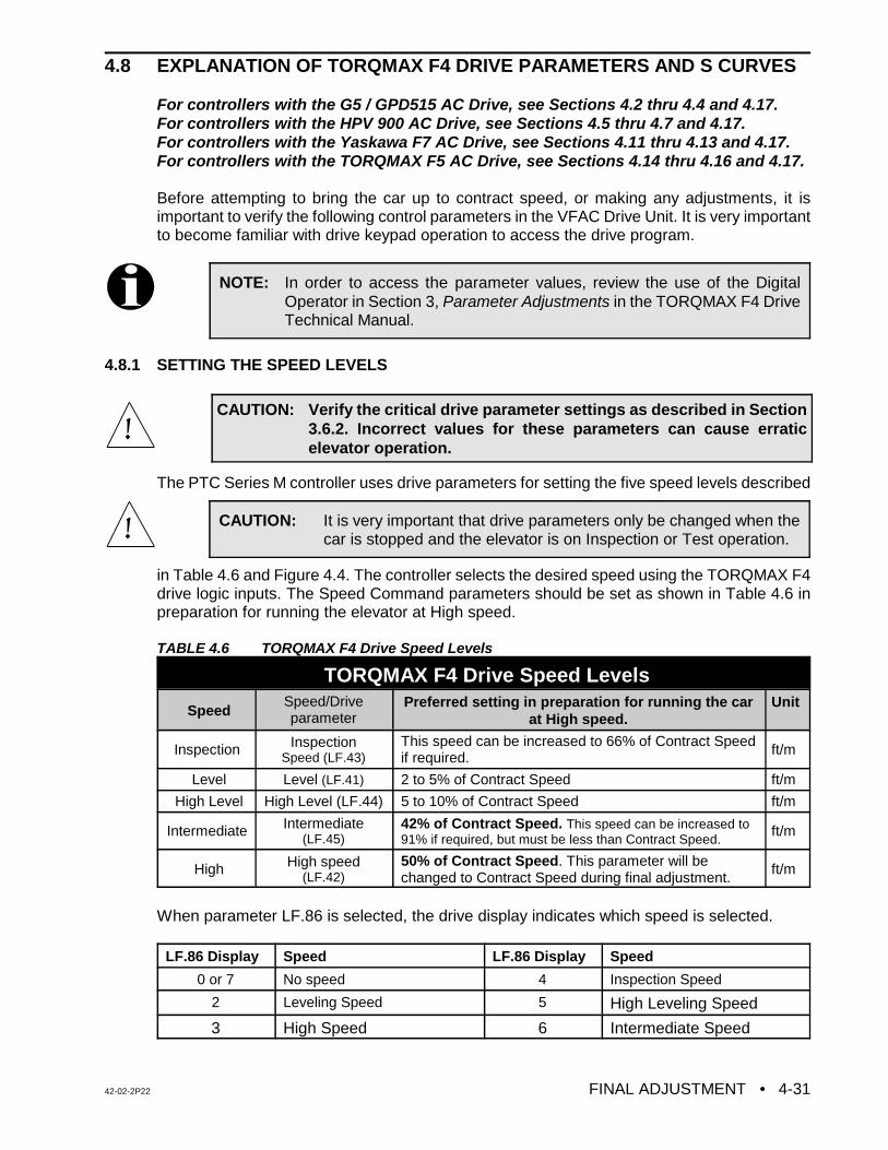
42-02-2P22 FINAL ADJUSTMENT • 4-31
NOTE: In order to access the parameter values, review the use of the DigitalOperator in Section 3, Parameter Adjustments in the TORQMAX F4 DriveTechnical Manual.
CAUTION: Verify the critical drive parameter settings as described in Section3.6.2. Incorrect values for these parameters can cause erraticelevator operation.
CAUTION: It is very important that drive parameters only be changed when thecar is stopped and the elevator is on Inspection or Test operation.
4.8 EXPLANATION OF TORQMAX F4 DRIVE PARAMETERS AND S CURVES
For controllers with the G5 / GPD515 AC Drive, see Sections 4.2 thru 4.4 and 4.17.For controllers with the HPV 900 AC Drive, see Sections 4.5 thru 4.7 and 4.17.For controllers with the Yaskawa F7 AC Drive, see Sections 4.11 thru 4.13 and 4.17.For controllers with the TORQMAX F5 AC Drive, see Sections 4.14 thru 4.16 and 4.17.
Before attempting to bring the car up to contract speed, or making any adjustments, it isimportant to verify the following control parameters in the VFAC Drive Unit. It is very importantto become familiar with drive keypad operation to access the drive program.
4.8.1 SETTING THE SPEED LEVELS
The PTC Series M controller uses drive parameters for setting the five speed levels described
in Table 4.6 and Figure 4.4. The controller selects the desired speed using the TORQMAX F4drive logic inputs. The Speed Command parameters should be set as shown in Table 4.6 inpreparation for running the elevator at High speed.
TABLE 4.6 TORQMAX F4 Drive Speed Levels
TORQMAX F4 Drive Speed Levels
SpeedSpeed/Driveparameter
Preferred setting in preparation for running the carat High speed.
Unit
Inspection InspectionSpeed (LF.43)
This speed can be increased to 66% of Contract Speedif required. ft/m
Level Level (LF.41) 2 to 5% of Contract Speed ft/m
High Level High Level (LF.44) 5 to 10% of Contract Speed ft/m
Intermediate Intermediate(LF.45)
42% of Contract Speed. This speed can be increased to91% if required, but must be less than Contract Speed.
ft/m
High High speed(LF.42)
50% of Contract Speed. This parameter will bechanged to Contract Speed during final adjustment.
ft/m
When parameter LF.86 is selected, the drive display indicates which speed is selected.
LF.86 Display Speed LF.86 Display Speed
0 or 7 No speed 4 Inspection Speed
2 Leveling Speed 5 High Leveling Speed
3 High Speed 6 Intermediate Speed
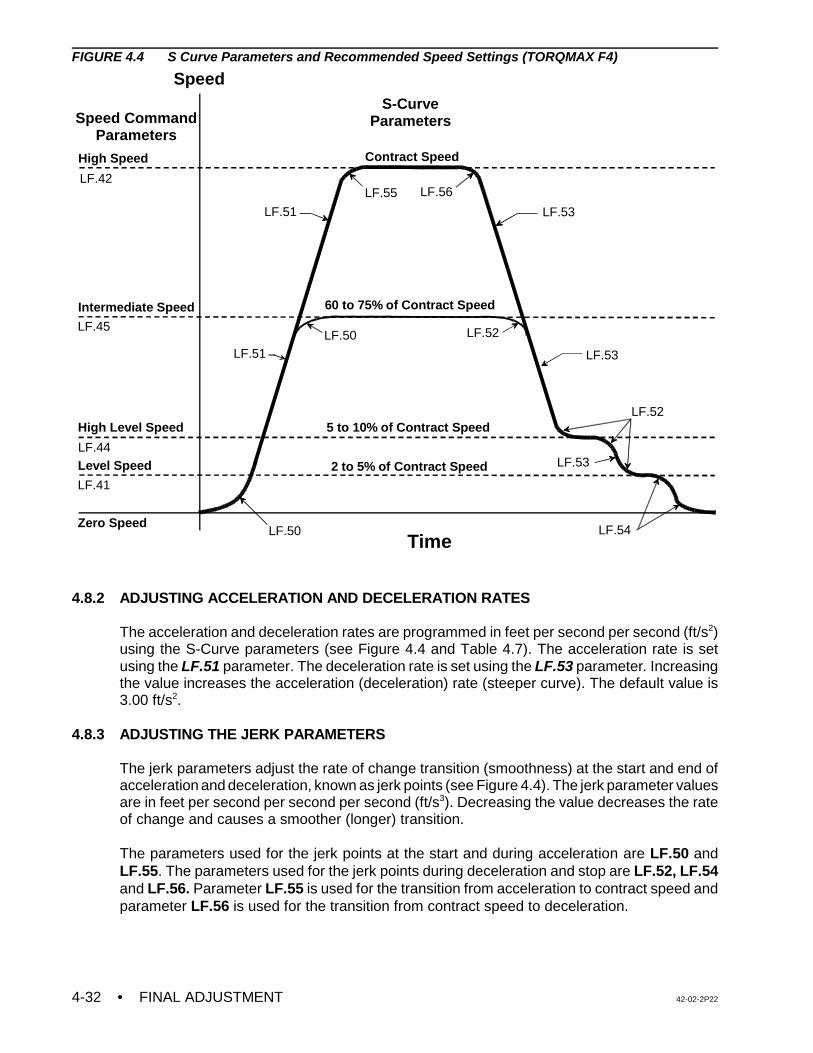
• FINAL ADJUSTMENT 42-02-2P224-32
Speed
TimeZero Speed
Level Speed
High Level Speed
Intermediate Speed
High Speed
LF.50
LF.51 LF.53
LF.54
LF.50
LF.55
LF.52
LF.52
Contract Speed
5 to 10% of Contract Speed
2 to 5% of Contract Speed
Speed CommandParameters
S-CurveParameters
LF.53
LF.53LF.51
60 to 75% of Contract Speed
LF.42
LF.45
LF.44
LF.41
LF.56
FIGURE 4.4 S Curve Parameters and Recommended Speed Settings (TORQMAX F4)
4.8.2 ADJUSTING ACCELERATION AND DECELERATION RATES
The acceleration and deceleration rates are programmed in feet per second per second (ft/s2)using the S-Curve parameters (see Figure 4.4 and Table 4.7). The acceleration rate is setusing the LF.51 parameter. The deceleration rate is set using the LF.53 parameter. Increasingthe value increases the acceleration (deceleration) rate (steeper curve). The default value is3.00 ft/s2.
4.8.3 ADJUSTING THE JERK PARAMETERS
The jerk parameters adjust the rate of change transition (smoothness) at the start and end ofacceleration and deceleration, known as jerk points (see Figure 4.4). The jerk parameter valuesare in feet per second per second per second (ft/s3). Decreasing the value decreases the rateof change and causes a smoother (longer) transition.
The parameters used for the jerk points at the start and during acceleration are LF.50 andLF.55. The parameters used for the jerk points during deceleration and stop are LF.52, LF.54and LF.56. Parameter LF.55 is used for the transition from acceleration to contract speed andparameter LF.56 is used for the transition from contract speed to deceleration.
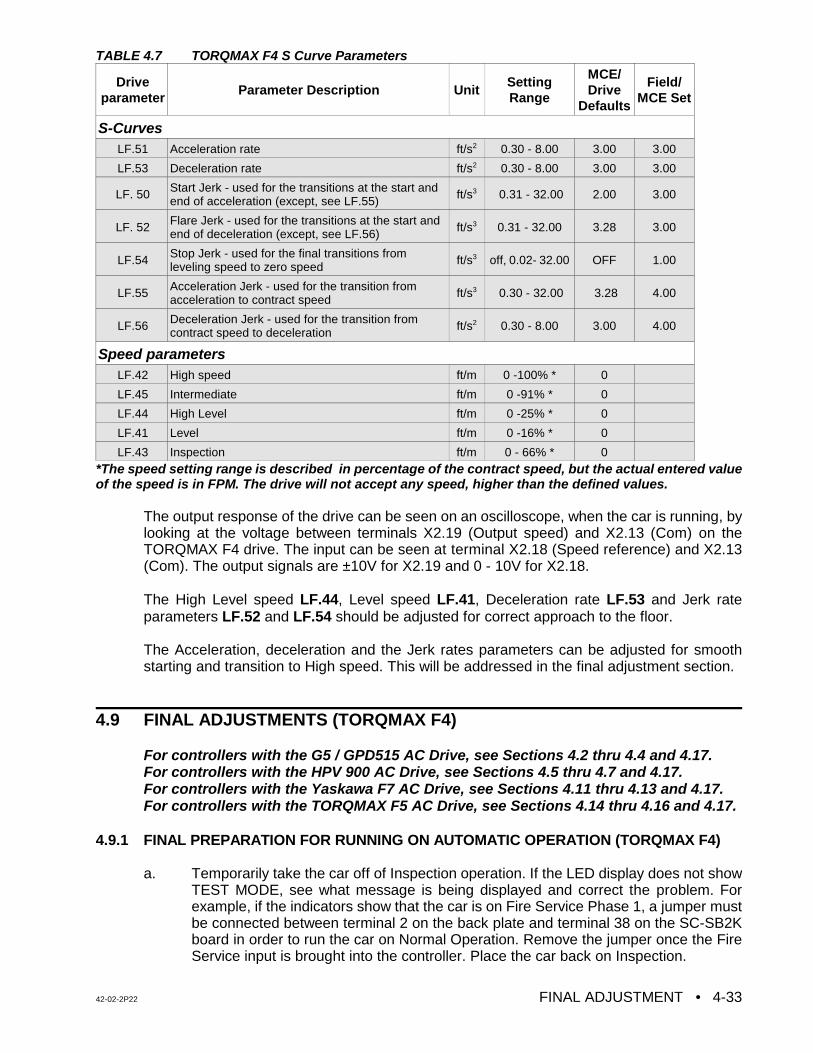
42-02-2P22 FINAL ADJUSTMENT • 4-33
TABLE 4.7 TORQMAX F4 S Curve Parameters
Driveparameter Parameter Description Unit
SettingRange
MCE/Drive
Defaults
Field/MCE Set
S-CurvesLF.51 Acceleration rate ft/s2 0.30 - 8.00 3.00 3.00
LF.53 Deceleration rate ft/s2 0.30 - 8.00 3.00 3.00
LF. 50 Start Jerk - used for the transitions at the start andend of acceleration (except, see LF.55) ft/s3 0.31 - 32.00 2.00 3.00
LF. 52 Flare Jerk - used for the transitions at the start andend of deceleration (except, see LF.56) ft/s3 0.31 - 32.00 3.28 3.00
LF.54 Stop Jerk - used for the final transitions fromleveling speed to zero speed ft/s3 off, 0.02- 32.00 OFF 1.00
LF.55 Acceleration Jerk - used for the transition fromacceleration to contract speed ft/s3 0.30 - 32.00 3.28 4.00
LF.56 Deceleration Jerk - used for the transition fromcontract speed to deceleration ft/s2 0.30 - 8.00 3.00 4.00
Speed parametersLF.42 High speed ft/m 0 -100% * 0
LF.45 Intermediate ft/m 0 -91% * 0
LF.44 High Level ft/m 0 -25% * 0
LF.41 Level ft/m 0 -16% * 0
LF.43 Inspection ft/m 0 - 66% * 0*The speed setting range is described in percentage of the contract speed, but the actual entered valueof the speed is in FPM. The drive will not accept any speed, higher than the defined values.
The output response of the drive can be seen on an oscilloscope, when the car is running, bylooking at the voltage between terminals X2.19 (Output speed) and X2.13 (Com) on theTORQMAX F4 drive. The input can be seen at terminal X2.18 (Speed reference) and X2.13(Com). The output signals are ±10V for X2.19 and 0 - 10V for X2.18.
The High Level speed LF.44, Level speed LF.41, Deceleration rate LF.53 and Jerk rateparameters LF.52 and LF.54 should be adjusted for correct approach to the floor.
The Acceleration, deceleration and the Jerk rates parameters can be adjusted for smoothstarting and transition to High speed. This will be addressed in the final adjustment section.
4.9 FINAL ADJUSTMENTS (TORQMAX F4)
For controllers with the G5 / GPD515 AC Drive, see Sections 4.2 thru 4.4 and 4.17.For controllers with the HPV 900 AC Drive, see Sections 4.5 thru 4.7 and 4.17.For controllers with the Yaskawa F7 AC Drive, see Sections 4.11 thru 4.13 and 4.17.For controllers with the TORQMAX F5 AC Drive, see Sections 4.14 thru 4.16 and 4.17.
4.9.1 FINAL PREPARATION FOR RUNNING ON AUTOMATIC OPERATION (TORQMAX F4)
a. Temporarily take the car off of Inspection operation. If the LED display does not showTEST MODE, see what message is being displayed and correct the problem. Forexample, if the indicators show that the car is on Fire Service Phase 1, a jumper mustbe connected between terminal 2 on the back plate and terminal 38 on the SC-SB2Kboard in order to run the car on Normal Operation. Remove the jumper once the FireService input is brought into the controller. Place the car back on Inspection.
• FINAL ADJUSTMENT 42-02-2P224-34
NOTE: It is very important that the drive parameters only be changed when the caris stopped and the elevator is on Inspection or Test operation so that thereis no demand.
b. Move the car to the bottom terminal landing. Check to see if the DZ relay is picked. Ifnot, move the car on Inspection to place it in the Door Zone.
4.9.2 SWITCHING TO AUTOMATIC OPERATION (TORQMAX F4)
Place the Relay Panel Inspection switch in the OFF position. If the car is not at a landing it willmove to a landing. If the car is at a landing but not in the door zone, relays L and either LU1/2or LD1/2 should pick and the car should perform a relevel. If the relevel in not successful, checkthe following:
C If the brake picks and the car is trying to level but is not able to, it may be necessary toadjust the Level Speed parameter (LF.41) on the TORQMAX F4 Drive to get the car tomove.
C If relays L (on HC-ACI) and LD1/2 and LEX (on SC-SB2K) are picked, but the brakeand other relays are not, the down direction limit switch may be preventing the levelingdown operation.
C If the car is trying to level, it will not leave the landing for a call until the leveling iscomplete. Move the limit switch if necessary.
The Status Indicator lights should now display the indication for Independent Service operation.At this time the Position Indicator should match the actual car location. Note that all of thePosition Indicators and direction arrows are conveniently displayed on the controller. All thecalls are also displayed on the controller.
4.9.3 BRAKE ADJUSTMENT FOR 125% LOAD (TORQMAX F4)
Put the car on Inspection at the bottom landing. Put 2/3 of a contract load in the car. Beginadding weights in 50 or 100 pound increments and move the car up and down on Inspectioneach time. Adjust the brake tension to stop and hold 125% of a contract load by tripping a stopswitch open while running down on Inspection. Hold the DOWN button in while tripping openthe stop switch (preferably on the Inspection station). KEEP THE CAR NEAR THE BOTTOMAS IT IS LIKELY TO SLIDE THROUGH THE BRAKE ONTO THE BUFFERS. If the AC DriveUnit trips on a fault when the car is going down, but not while it is going up, refer to the manualfor the VFAC Drive Unit and look up the failure indicated on the Drive display. If the displayedfault is E.OP (over-voltage fault), there may be a problem in the regeneration (or braking)resistors, the braking module (if one is provided), or in the fuses that may be in series with thewires to the braking resistors.
If there is a problem lifting the load, Set parameter LF.38 = 0 (PWM = 8KHz). Then increasethe drive gain using parameters LF.31 and LF.32. If this problem cannot be solved, call MCETechnical Support.
4.9.4 BRINGING THE CAR UP TO HIGH SPEED (TORQMAX F4)
a. Remove all test weights from the car. Verify that all the steps described in Sections 4.1and 4.8 regarding the adjustments and specifically the drive parameters are complete.
42-02-2P22 FINAL ADJUSTMENT • 4-35
NOTE: Drive gain adjustments - The default values for the gain parameters(LF.31 Speed Prop Gain and LF.32 Speed Integral Gain) may not besufficient to run the car on High speed. It may be necessary to increase thevalue of these parameters.
NOTE: To observe the commanded speed and the drive output with anoscilloscope or a chart recorder, monitor drive terminal X2.18 and X2.19with respect to X2.13. Take all necessary precautions while measuring thevoltage signals.
b. Register a car call one floor above the car. The High speed relay (H) shouldpick and the drive keypad display should read 50% of Contract Speed as thecar attempts to start. If the car runs normally, commence multi-floor runs andslowly increase High speed by increasing parameter LF.42 until ContractSpeed is achieved. If there is a problem reaching Contract Speed, see thefollowing note.
c. At the slowdown distance from the next floor the Position Indicator will step. Afterstepping occurs, High speed is dropped and the car should rapidly decelerate to HighLevel speed. Reduce the High Level speed (LF.44) so that the car runs at about 10 -20 fpm or at a reasonable speed (use your personal judgment). Six inches before thefloor at which the car is to stop, High Level speed is dropped and the car shoulddecelerate to Level speed. The Level speed can be adjusted using parameter LF.41 sothat the car levels into the floor and stops. Level speed should be 7 - 12 fpm, or areasonable leveling speed (use personal judgement). If the car re-levels frequently onceLevel speed is adjusted satisfactorily, spread apart the LU and LD sensors or switchesin the landing system to provide enough Dead Zone.
d. Turn the Speed Pick Delay (SPD) trimpot fully CCW (fully OFF) and then set it 1/4 turnin the CW direction. The speed pick delay is achieved using the TORQMAX F4 driveparameter LF.70. Adjust LF.70 so that the brake is fully picked just as the motor firstmoves. The goal is to delay the speed command long enough to avoid moving themotor before the brake is fully lifted, but not so long as to allow the car to roll back.
e. Run the car again and verify that the car will start, accelerate, decelerate and run atHigh Level and Level speeds into the floor and stop. Place calls for all of the landings.Verify that all of the calls work. Verify the operation and placement of all vanes ormagnets and vane or magnet switches and verify that the car steps the PositionIndicators correctly. The slowdown distance for the elevator is measured from the pointwhere the STU sensor (or STD sensor, if going down) is activated by a metal vane ormagnetic strip to the position where the car is stopped at the floor with the DZ sensorcentered on the leveling target with LU or LD sensors not engaged.
This slowdown distance was chosen to give a reasonable deceleration rate. Continueto make two-floor runs and slowly increase High speed until Contract Speed is reached.It may be necessary to adjust the Deceleration rate (LF.53) and deceleration jerk rate(LF.52) to stop the car at the floor. Adjust the Acceleration rate parameter (LF.51) untilthe desired acceleration rate is achieved. Several runs may be required to obtainoptimum acceleration. The acceleration rate should be about the same as thedeceleration rate.
• FINAL ADJUSTMENT 42-02-2P224-36
CAUTION: Most oscilloscopes have a grounding pin on their power plug. Werecommend defeating the grounding pin with one of the commonlyavailable ground isolation adapter plugs so that the case of theoscilloscope is not at ground potential, but at whatever potential thenegative probe lead is connected to. TREAT THE CASE OF THEOSCILLOSCOPE AS A LETHAL SHOCK HAZARD, DEPENDINGON WHERE THE NEGATIVE PROBE IS CONNECTED. Thisrecommendation is being made because the ground potential on thegrounding pin of the power outlet may not be the same as thecontroller cabinet ground. If it is not, substantial ground loop currentmay flow between the negative probe and the power plug groundingpin which can ruin the oscilloscope
NOTE: During High speed, if the speed change-over can be felt in the car,increase parameter LF.33 in steps of 100. This will help in achieving asmoother transition.
f. To achieve a proper start, without rollback (or snapping away from the floor), a variabledelay in the application of the speed signal is provided using drive parameter LF.70.Parameter LF.70 must be adjusted to let the brake just clear the brake drum beforeattempting to accelerate the car. Do this with an empty car. The correct setting will beobvious by watching the Drive sheave. This was adjusted previously; however, checkparameter LF.70 again and make adjustments if necessary. The response of the carcan be monitored using an oscilloscope by measuring the voltage on the drive terminalsX2.18 and X2.19 with respect to X2.13. These signals are ±10V and 0-10 Vrespectively. Terminal X2.18 is assigned to the drive input speed reference and terminalX2.19 is assigned to the drive output frequency.
g. The car should be running well now, except possibly for the final stop. Since the speedreference goes to zero when the car stops, the VFAC Drive Unit will cause the machineto stop electrically. Enough delay in the setting of the brake (BDD) will have to beprovided to allow the sheave to stop turning before setting the brake firmly on thesheave .
When the elevator slows down to leveling speed and travels to door zone, the speedcommand will drop to zero before the brake drops. This is adjustable using the BDD(Brake Drop Delay) trimpot. The idea is to hold the brake up long enough to allow themotor to be stopped electrically and then drop the brake immediately the instant themotor has stopped.
If there is too long of a delay before dropping the brake, the control system will releaseits control of the motor and the motor will drift briefly in the direction of the load beforethe brake is forced to drop by the PT relay. The BDD trimpot controls the dropping ofthe brake through the BE relay. Move the LU and LD sensors or switches closertogether (or further apart) so the car stops at the same location, up or down. Then movethe floor (leveling) magnet strips or vanes so the car stops accurately at each floor.
h. The adjustment is almost complete. The acceleration rate parameter setting should beat least as great as the deceleration rate parameter, but it should not be so high that itsubstantially exceeds the value of the deceleration rate parameter. Excessiveacceleration may cause the AC Drive circuits to saturate and thereby lose control of thecar. Ideally, the slope of the acceleration in volts per second should be equal to theslope of the deceleration. Note the present value of the deceleration parameter LF. 53and run the car. Continue to decrease the value of LF.53 until the car overshoots the
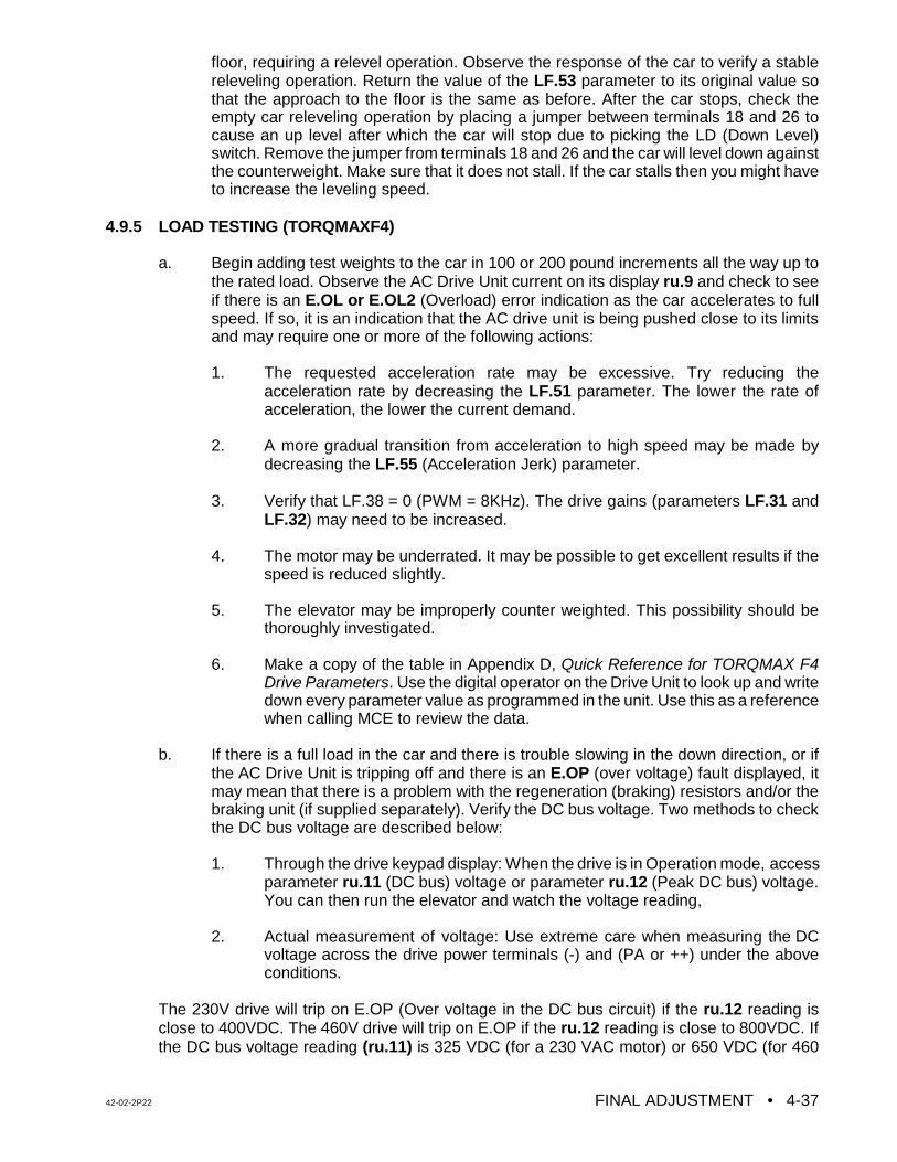
42-02-2P22 FINAL ADJUSTMENT • 4-37
floor, requiring a relevel operation. Observe the response of the car to verify a stablereleveling operation. Return the value of the LF.53 parameter to its original value sothat the approach to the floor is the same as before. After the car stops, check theempty car releveling operation by placing a jumper between terminals 18 and 26 tocause an up level after which the car will stop due to picking the LD (Down Level)switch. Remove the jumper from terminals 18 and 26 and the car will level down againstthe counterweight. Make sure that it does not stall. If the car stalls then you might haveto increase the leveling speed.
4.9.5 LOAD TESTING (TORQMAXF4)
a. Begin adding test weights to the car in 100 or 200 pound increments all the way up tothe rated load. Observe the AC Drive Unit current on its display ru.9 and check to seeif there is an E.OL or E.OL2 (Overload) error indication as the car accelerates to fullspeed. If so, it is an indication that the AC drive unit is being pushed close to its limitsand may require one or more of the following actions:
1. The requested acceleration rate may be excessive. Try reducing theacceleration rate by decreasing the LF.51 parameter. The lower the rate ofacceleration, the lower the current demand.
2. A more gradual transition from acceleration to high speed may be made bydecreasing the LF.55 (Acceleration Jerk) parameter.
3. Verify that LF.38 = 0 (PWM = 8KHz). The drive gains (parameters LF.31 andLF.32) may need to be increased.
4. The motor may be underrated. It may be possible to get excellent results if thespeed is reduced slightly.
5. The elevator may be improperly counter weighted. This possibility should bethoroughly investigated.
6. Make a copy of the table in Appendix D, Quick Reference for TORQMAX F4Drive Parameters. Use the digital operator on the Drive Unit to look up and writedown every parameter value as programmed in the unit. Use this as a referencewhen calling MCE to review the data.
b. If there is a full load in the car and there is trouble slowing in the down direction, or ifthe AC Drive Unit is tripping off and there is an E.OP (over voltage) fault displayed, itmay mean that there is a problem with the regeneration (braking) resistors and/or thebraking unit (if supplied separately). Verify the DC bus voltage. Two methods to checkthe DC bus voltage are described below:
1. Through the drive keypad display: When the drive is in Operation mode, accessparameter ru.11 (DC bus) voltage or parameter ru.12 (Peak DC bus) voltage.You can then run the elevator and watch the voltage reading,
2. Actual measurement of voltage: Use extreme care when measuring the DCvoltage across the drive power terminals (-) and (PA or ++) under the aboveconditions.
The 230V drive will trip on E.OP (Over voltage in the DC bus circuit) if the ru.12 reading isclose to 400VDC. The 460V drive will trip on E.OP if the ru.12 reading is close to 800VDC. Ifthe DC bus voltage reading (ru.11) is 325 VDC (for a 230 VAC motor) or 650 VDC (for 460
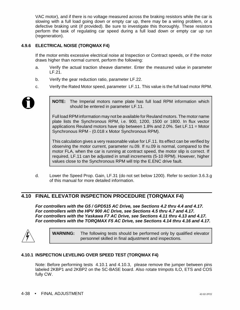
• FINAL ADJUSTMENT 42-02-2P224-38
NOTE: The Imperial motors name plate has full load RPM information whichshould be entered in parameter LF.11.
Full load RPM information may not be available for Reuland motors. The motor nameplate lists the Synchronous RPM, i.e. 900, 1200, 1500 or 1800. In flux vectorapplications Reuland motors have slip between 1.8% and 2.0%. Set LF.11 = MotorSynchronous RPM - (0.018 x Motor Synchronous RPM).
This calculation gives a very reasonable value for LF.11. Its effect can be verified byobserving the motor current, parameter ru.09. If ru.09 is normal, compared to themotor FLA, when the car is running at contract speed, the motor slip is correct. Ifrequired, LF.11 can be adjusted in small increments (5-10 RPM). However, highervalues close to the Synchronous RPM will trip the E.ENC drive fault.
WARNING: The following tests should be performed only by qualified elevatorpersonnel skilled in final adjustment and inspections.
VAC motor), and if there is no voltage measured across the braking resistors while the car isslowing with a full load going down or empty car up, there may be a wiring problem, or adefective braking unit (if provided). Be sure to investigate this thoroughly. These resistorsperform the task of regulating car speed during a full load down or empty car up run(regeneration).
4.9.6 ELECTRICAL NOISE (TORQMAX F4)
If the motor emits excessive electrical noise at Inspection or Contract speeds, or if the motordraws higher than normal current, perform the following:
a. Verify the actual traction sheave diameter. Enter the measured value in parameterLF.21.
b. Verify the gear reduction ratio, parameter LF.22.
c. Verify the Rated Motor speed, parameter LF.11. This value is the full load motor RPM.
d. Lower the Speed Prop. Gain, LF.31 (do not set below 1200). Refer to section 3.6.3.gof this manual for more detailed information.
4.10 FINAL ELEVATOR INSPECTION PROCEDURE (TORQMAX F4)
For controllers with the G5 / GPD515 AC Drive, see Sections 4.2 thru 4.4 and 4.17.For controllers with the HPV 900 AC Drive, see Sections 4.5 thru 4.7 and 4.17.For controllers with the Yaskawa F7 AC Drive, see Sections 4.11 thru 4.13 and 4.17.For controllers with the TORQMAX F5 AC Drive, see Sections 4.14 thru 4.16 and 4.17.
4.10.1 INSPECTION LEVELING OVER SPEED TEST (TORQMAX F4)
Note: Before performing tests 4.10.1 and 4.10.3, please remove the jumper between pinslabeled 2KBP1 and 2KBP2 on the SC-BASE board. Also rotate trimpots ILO, ETS and COSfully CW.
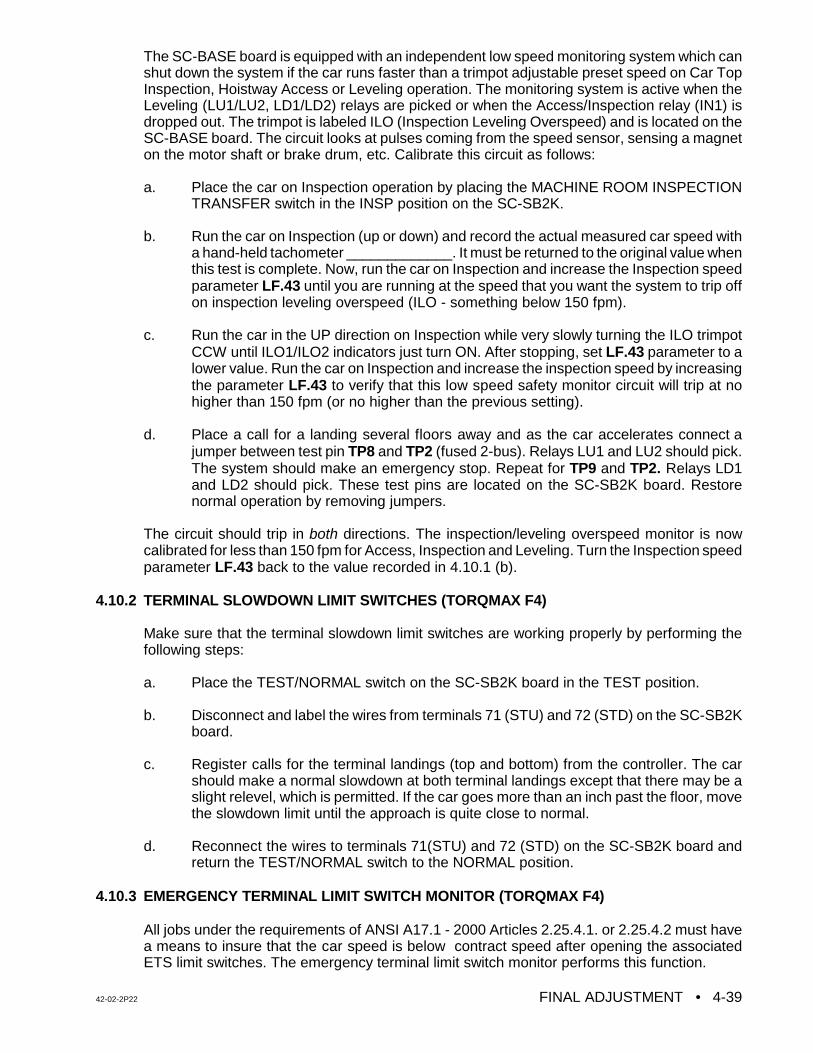
42-02-2P22 FINAL ADJUSTMENT • 4-39
The SC-BASE board is equipped with an independent low speed monitoring system which canshut down the system if the car runs faster than a trimpot adjustable preset speed on Car TopInspection, Hoistway Access or Leveling operation. The monitoring system is active when theLeveling (LU1/LU2, LD1/LD2) relays are picked or when the Access/Inspection relay (IN1) isdropped out. The trimpot is labeled ILO (Inspection Leveling Overspeed) and is located on theSC-BASE board. The circuit looks at pulses coming from the speed sensor, sensing a magneton the motor shaft or brake drum, etc. Calibrate this circuit as follows:
a. Place the car on Inspection operation by placing the MACHINE ROOM INSPECTIONTRANSFER switch in the INSP position on the SC-SB2K.
b. Run the car on Inspection (up or down) and record the actual measured car speed witha hand-held tachometer _____________. It must be returned to the original value whenthis test is complete. Now, run the car on Inspection and increase the Inspection speedparameter LF.43 until you are running at the speed that you want the system to trip offon inspection leveling overspeed (ILO - something below 150 fpm).
c. Run the car in the UP direction on Inspection while very slowly turning the ILO trimpotCCW until ILO1/ILO2 indicators just turn ON. After stopping, set LF.43 parameter to alower value. Run the car on Inspection and increase the inspection speed by increasingthe parameter LF.43 to verify that this low speed safety monitor circuit will trip at nohigher than 150 fpm (or no higher than the previous setting).
d. Place a call for a landing several floors away and as the car accelerates connect ajumper between test pin TP8 and TP2 (fused 2-bus). Relays LU1 and LU2 should pick.The system should make an emergency stop. Repeat for TP9 and TP2. Relays LD1and LD2 should pick. These test pins are located on the SC-SB2K board. Restorenormal operation by removing jumpers.
The circuit should trip in both directions. The inspection/leveling overspeed monitor is nowcalibrated for less than 150 fpm for Access, Inspection and Leveling. Turn the Inspection speedparameter LF.43 back to the value recorded in 4.10.1 (b).
4.10.2 TERMINAL SLOWDOWN LIMIT SWITCHES (TORQMAX F4)
Make sure that the terminal slowdown limit switches are working properly by performing thefollowing steps:
a. Place the TEST/NORMAL switch on the SC-SB2K board in the TEST position.
b. Disconnect and label the wires from terminals 71 (STU) and 72 (STD) on the SC-SB2Kboard.
c. Register calls for the terminal landings (top and bottom) from the controller. The carshould make a normal slowdown at both terminal landings except that there may be aslight relevel, which is permitted. If the car goes more than an inch past the floor, movethe slowdown limit until the approach is quite close to normal.
d. Reconnect the wires to terminals 71(STU) and 72 (STD) on the SC-SB2K board andreturn the TEST/NORMAL switch to the NORMAL position.
4.10.3 EMERGENCY TERMINAL LIMIT SWITCH MONITOR (TORQMAX F4)
All jobs under the requirements of ANSI A17.1 - 2000 Articles 2.25.4.1. or 2.25.4.2 must havea means to insure that the car speed is below contract speed after opening the associatedETS limit switches. The emergency terminal limit switch monitor performs this function.
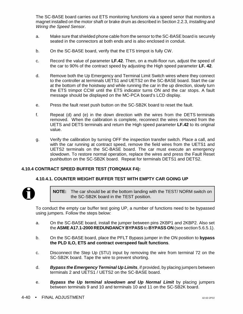
• FINAL ADJUSTMENT 42-02-2P224-40
NOTE: The car should be at the bottom landing with the TEST/ NORM switch onthe SC-SB2K board in the TEST position.
The SC-BASE board carries out ETS monitoring functions via a speed senor that monitors amagnet installed on the motor shaft or brake drum as described in Section 2.2.3, Installing andWiring the Speed Sensor.
a. Make sure that shielded phone cable from the sensor to the SC-BASE board is securelyseated in the connectors at both ends and is also enclosed in conduit.
b. On the SC-BASE board, verify that the ETS trimpot is fully CW.
c. Record the value of parameter LF.42. Then, on a multi-floor run, adjust the speed ofthe car to 90% of the contract speed by adjusting the High speed parameter LF. 42.
d. Remove both the Up Emergency and Terminal Limit Switch wires where they connectto the controller at terminals UETS1 and UETS2 on the SC-BASE board. Start the carat the bottom of the hoistway and while running the car in the up direction, slowly turnthe ETS trimpot CCW until the ETS indicator turns ON and the car stops. A faultmessage should be displayed on the MC-PCA board’s LCD display.
e. Press the fault reset push button on the SC-SB2K board to reset the fault.
f. Repeat (d) and (e) in the down direction with the wires from the DETS terminalsremoved. When the calibration is complete, reconnect the wires removed from theUETS and DETS terminals and return the High speed parameter LF.42 to its originalvalue.
g. Verify the calibration by turning OFF the inspection transfer switch. Place a call, andwith the car running at contract speed, remove the field wires from the UETS1 andUETS2 terminals on the SC-BASE board. The car must execute an emergencyslowdown. To restore normal operation, replace the wires and press the Fault Resetpushbutton on the SC-SB2K board. Repeat for terminals DETS1 and DETS2.
4.10.4 CONTRACT SPEED BUFFER TEST (TORQMAX F4):
4.10.4.1. COUNTER WEIGHT BUFFER TEST WITH EMPTY CAR GOING UP
To conduct the empty car buffer test going UP, a number of functions need to be bypassedusing jumpers. Follow the steps below:
a. On the SC-BASE board, install the jumper between pins 2KBP1 and 2KBP2. Also setthe ASME A17.1-2000 REDUNDANCY BYPASS to BYPASS ON (see section 5.6.5.1).
b. On the SC-BASE board, place the PFLT Bypass jumper in the ON position to bypassthe PLD ILO, ETS and contract overspeed fault functions.
c. Disconnect the Step Up (STU) input by removing the wire from terminal 72 on theSC-SB2K board. Tape the wire to prevent shorting.
d. Bypass the Emergency Terminal Up Limits, if provided, by placing jumpers betweenterminals 2 and UETS1 / UETS2 on the SC-BASE board.
e. Bypass the Up terminal slowdown and Up Normal Limit by placing jumpersbetween terminals 9 and 10 and terminals 10 and 11 on the SC-SB2K board.
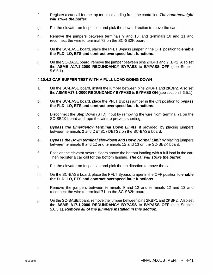
42-02-2P22 FINAL ADJUSTMENT • 4-41
f. Register a car call for the top terminal landing from the controller. The counterweightwill strike the buffer.
g. Put the elevator on Inspection and pick the down direction to move the car.
h. Remove the jumpers between terminals 9 and 10, and terminals 10 and 11 andreconnect the wire to terminal 72 on the SC-SB2K board.
i. On the SC-BASE board, place the PFLT Bypass jumper in the OFF position to enablethe PLD ILO, ETS and contract overspeed fault functions.
j. On the SC-BASE board, remove the jumper between pins 2KBP1 and 2KBP2. Also setthe ASME A17.1-2000 REDUNDANCY BYPASS to BYPASS OFF (see Section5.6.5.1).
4.10.4.2 CAR BUFFER TEST WITH A FULL LOAD GOING DOWN
a. On the SC-BASE board, install the jumper between pins 2KBP1 and 2KBP2. Also setthe ASME A17.1-2000 REDUNDANCY BYPASS to BYPASS ON (see section 5.6.5.1).
b. On the SC-BASE board, place the PFLT Bypass jumper in the ON position to bypassthe PLD ILO, ETS and contract overspeed fault functions.
c. Disconnect the Step Down (STD) input by removing the wire from terminal 71 on theSC-SB2K board and tape the wire to prevent shorting.
d. Bypass the Emergency Terminal Down Limits, if provided, by placing jumpersbetween terminals 2 and DETS1 / DETS2 on the SC-BASE board.
e. Bypass the Down terminal slowdown and Down Normal Limit by placing jumpersbetween terminals 9 and 12 and terminals 12 and 13 on the SC-SB2K board.
f. Position the elevator several floors above the bottom landing with a full load in the car.Then register a car call for the bottom landing. The car will strike the buffer.
g. Put the elevator on Inspection and pick the up direction to move the car.
h. On the SC-BASE board, place the PFLT Bypass jumper in the OFF position to enablethe PLD ILO, ETS and contract overspeed fault functions.
i. Remove the jumpers between terminals 9 and 12 and terminals 12 and 13 andreconnect the wire to terminal 71 on the SC-SB2K board.
j. On the SC-BASE board, remove the jumper between pins 2KBP1 and 2KBP2. Also setthe ASME A17.1-2000 REDUNDANCY BYPASS to BYPASS OFF (see Section5.6.5.1). Remove all of the jumpers installed in this section.
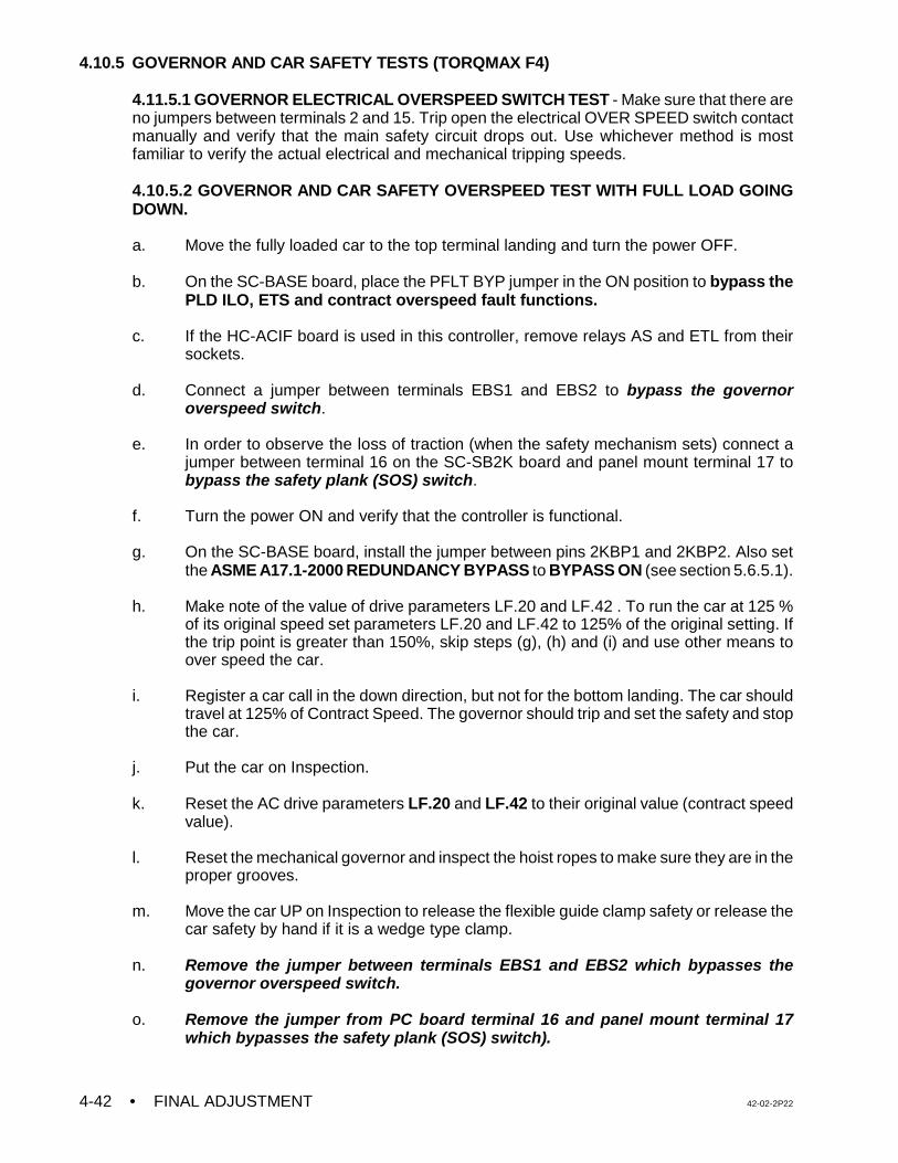
• FINAL ADJUSTMENT 42-02-2P224-42
4.10.5 GOVERNOR AND CAR SAFETY TESTS (TORQMAX F4)
4.11.5.1 GOVERNOR ELECTRICAL OVERSPEED SWITCH TEST - Make sure that there areno jumpers between terminals 2 and 15. Trip open the electrical OVER SPEED switch contactmanually and verify that the main safety circuit drops out. Use whichever method is mostfamiliar to verify the actual electrical and mechanical tripping speeds.
4.10.5.2 GOVERNOR AND CAR SAFETY OVERSPEED TEST WITH FULL LOAD GOINGDOWN.
a. Move the fully loaded car to the top terminal landing and turn the power OFF.
b. On the SC-BASE board, place the PFLT BYP jumper in the ON position to bypass thePLD ILO, ETS and contract overspeed fault functions.
c. If the HC-ACIF board is used in this controller, remove relays AS and ETL from their
sockets.
d. Connect a jumper between terminals EBS1 and EBS2 to bypass the governoroverspeed switch.
e. In order to observe the loss of traction (when the safety mechanism sets) connect a
jumper between terminal 16 on the SC-SB2K board and panel mount terminal 17 tobypass the safety plank (SOS) switch.
f. Turn the power ON and verify that the controller is functional.
g. On the SC-BASE board, install the jumper between pins 2KBP1 and 2KBP2. Also setthe ASME A17.1-2000 REDUNDANCY BYPASS to BYPASS ON (see section 5.6.5.1).
h. Make note of the value of drive parameters LF.20 and LF.42 . To run the car at 125 %of its original speed set parameters LF.20 and LF.42 to 125% of the original setting. Ifthe trip point is greater than 150%, skip steps (g), (h) and (i) and use other means toover speed the car.
i. Register a car call in the down direction, but not for the bottom landing. The car shouldtravel at 125% of Contract Speed. The governor should trip and set the safety and stopthe car.
j. Put the car on Inspection.
k. Reset the AC drive parameters LF.20 and LF.42 to their original value (contract speedvalue).
l. Reset the mechanical governor and inspect the hoist ropes to make sure they are in theproper grooves.
m. Move the car UP on Inspection to release the flexible guide clamp safety or release thecar safety by hand if it is a wedge type clamp.
n. Remove the jumper between terminals EBS1 and EBS2 which bypasses thegovernor overspeed switch.
o. Remove the jumper from PC board terminal 16 and panel mount terminal 17which bypasses the safety plank (SOS) switch).
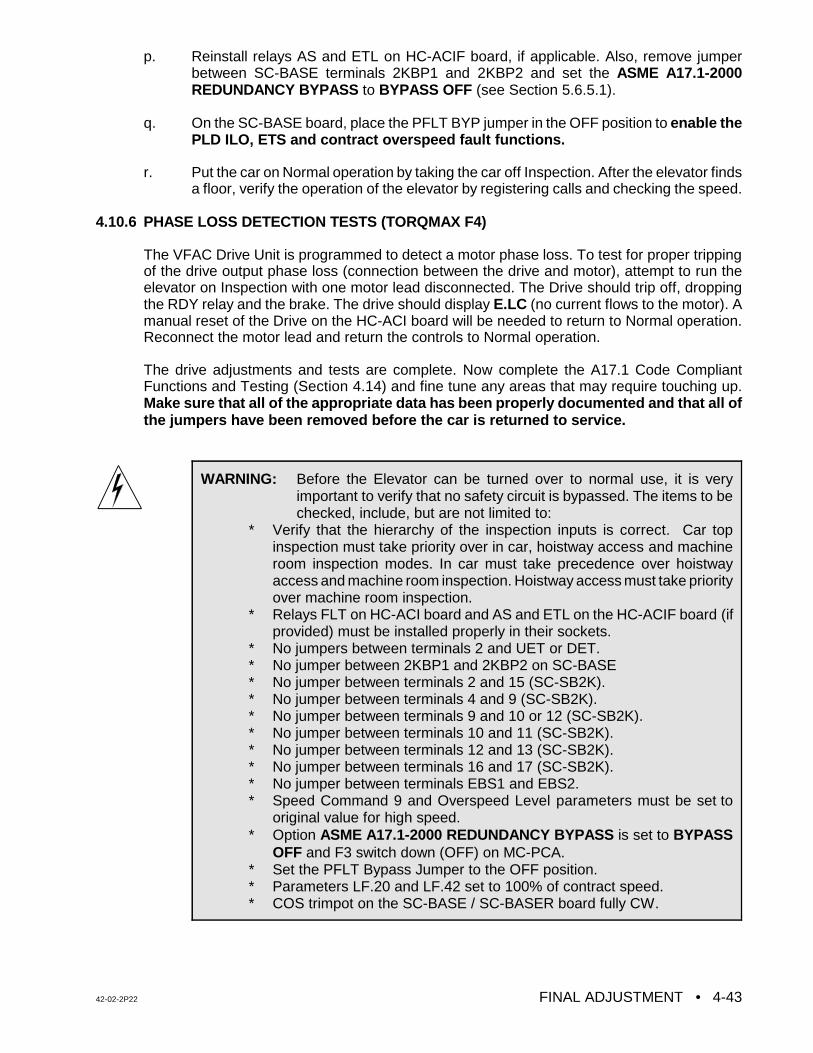
42-02-2P22 FINAL ADJUSTMENT • 4-43
WARNING: Before the Elevator can be turned over to normal use, it is veryimportant to verify that no safety circuit is bypassed. The items to bechecked, include, but are not limited to:
* Verify that the hierarchy of the inspection inputs is correct. Car topinspection must take priority over in car, hoistway access and machineroom inspection modes. In car must take precedence over hoistwayaccess and machine room inspection. Hoistway access must take priorityover machine room inspection.
* Relays FLT on HC-ACI board and AS and ETL on the HC-ACIF board (ifprovided) must be installed properly in their sockets.
* No jumpers between terminals 2 and UET or DET.* No jumper between 2KBP1 and 2KBP2 on SC-BASE* No jumper between terminals 2 and 15 (SC-SB2K).* No jumper between terminals 4 and 9 (SC-SB2K).* No jumper between terminals 9 and 10 or 12 (SC-SB2K).* No jumper between terminals 10 and 11 (SC-SB2K).* No jumper between terminals 12 and 13 (SC-SB2K).* No jumper between terminals 16 and 17 (SC-SB2K).* No jumper between terminals EBS1 and EBS2.* Speed Command 9 and Overspeed Level parameters must be set to
original value for high speed.* Option ASME A17.1-2000 REDUNDANCY BYPASS is set to BYPASS
OFF and F3 switch down (OFF) on MC-PCA. * Set the PFLT Bypass Jumper to the OFF position.* Parameters LF.20 and LF.42 set to 100% of contract speed.* COS trimpot on the SC-BASE / SC-BASER board fully CW.
p. Reinstall relays AS and ETL on HC-ACIF board, if applicable. Also, remove jumperbetween SC-BASE terminals 2KBP1 and 2KBP2 and set the ASME A17.1-2000REDUNDANCY BYPASS to BYPASS OFF (see Section 5.6.5.1).
q. On the SC-BASE board, place the PFLT BYP jumper in the OFF position to enable thePLD ILO, ETS and contract overspeed fault functions.
r. Put the car on Normal operation by taking the car off Inspection. After the elevator findsa floor, verify the operation of the elevator by registering calls and checking the speed.
4.10.6 PHASE LOSS DETECTION TESTS (TORQMAX F4)
The VFAC Drive Unit is programmed to detect a motor phase loss. To test for proper trippingof the drive output phase loss (connection between the drive and motor), attempt to run theelevator on Inspection with one motor lead disconnected. The Drive should trip off, droppingthe RDY relay and the brake. The drive should display E.LC (no current flows to the motor). Amanual reset of the Drive on the HC-ACI board will be needed to return to Normal operation.Reconnect the motor lead and return the controls to Normal operation.
The drive adjustments and tests are complete. Now complete the A17.1 Code CompliantFunctions and Testing (Section 4.14) and fine tune any areas that may require touching up.Make sure that all of the appropriate data has been properly documented and that all ofthe jumpers have been removed before the car is returned to service.
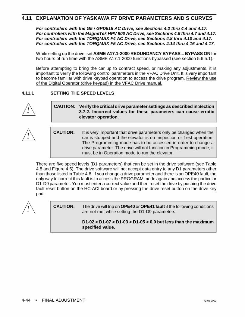
• FINAL ADJUSTMENT 42-02-2P224-44
CAUTION: Verify the critical drive parameter settings as described in Section3.7.2. Incorrect values for these parameters can cause erraticelevator operation.
CAUTION: It is very important that drive parameters only be changed when thecar is stopped and the elevator is on Inspection or Test operation.The Programming mode has to be accessed in order to change adrive parameter. The drive will not function in Programming mode, itmust be in Operation mode to run the elevator.
CAUTION: The drive will trip on OPE40 or OPE41 fault if the following conditionsare not met while setting the D1-D9 parameters:
D1-02 > D1-07 > D1-03 > D1-05 > 0.0 but less than the maximumspecified value.
4.11 EXPLANATION OF YASKAWA F7 DRIVE PARAMETERS AND S CURVES
For controllers with the G5 / GPD515 AC Drive, see Sections 4.2 thru 4.4 and 4.17.For controllers with the MagneTek HPV 900 AC Drive, see Sections 4.5 thru 4.7 and 4.17.For controllers with the TORQMAX F4 AC Drive, see Sections 4.8 thru 4.10 and 4.17.For controllers with the TORQMAX F5 AC Drive, see Sections 4.14 thru 4.16 and 4.17.
While setting up the drive, set ASME A17.1-2000 REDUNDANCY BYPASS = BYPASS ON fortwo hours of run time with the ASME A17.1-2000 functions bypassed (see section 5.6.5.1).
Before attempting to bring the car up to contract speed, or making any adjustments, it isimportant to verify the following control parameters in the VFAC Drive Unit. It is very importantto become familiar with drive keypad operation to access the drive program. Review the useof the Digital Operator (drive keypad) in the VFAC Drive manual.
4.11.1 SETTING THE SPEED LEVELS
There are five speed levels (D1 parameters) that can be set in the drive software (see Table4.8 and Figure 4.5). The drive software will not accept data entry to any D1 parameters otherthan those listed in Table 4.8. If you change a drive parameter and there is an OPE40 fault, theonly way to correct this fault is to access the PROGRAM mode again and access the particularD1-D9 parameter. You must enter a correct value and then reset the drive by pushing the drivefault reset button on the HC-ACI board or by pressing the drive reset button on the drive keypad.
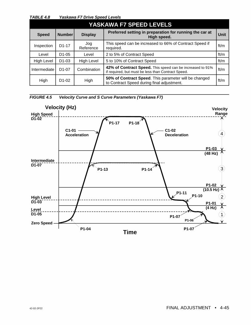
42-02-2P22 FINAL ADJUSTMENT • 4-45
Velocity (Hz)
Time
Zero Speed
Level D1-05
High LevelD1-03
IntermediateD1-07
High SpeedD1-02
P1-04
C1-01 Acceleration
C1-02 Deceleration
P1-13 P1-14
P1-11P1-10
P1-07P1-06
P1-07
P1-17 P1-18
P1-03 (48 Hz)
P1-02 (10.5 Hz)
P1-01 (4 Hz)
1
2
3
4
VelocityRange
TABLE 4.8 Yaskawa F7 Drive Speed Levels
YASKAWA F7 SPEED LEVELS
Speed Number Display Preferred setting in preparation for running the car atHigh speed. Unit
Inspection D1-17 JogReference
This speed can be increased to 66% of Contract Speed ifrequired. ft/m
Level D1-05 Level 2 to 5% of Contract Speed ft/m
High Level D1-03 High Level 5 to 10% of Contract Speed ft/m
Intermediate D1-07 Combination 42% of Contract Speed. This speed can be increased to 91%if required, but must be less than Contract Speed.
ft/m
High D1-02 High 50% of Contract Speed. This parameter will be changedto Contract Speed during final adjustment.
ft/m
FIGURE 4.5 Velocity Curve and S Curve Parameters (Yaskawa F7)
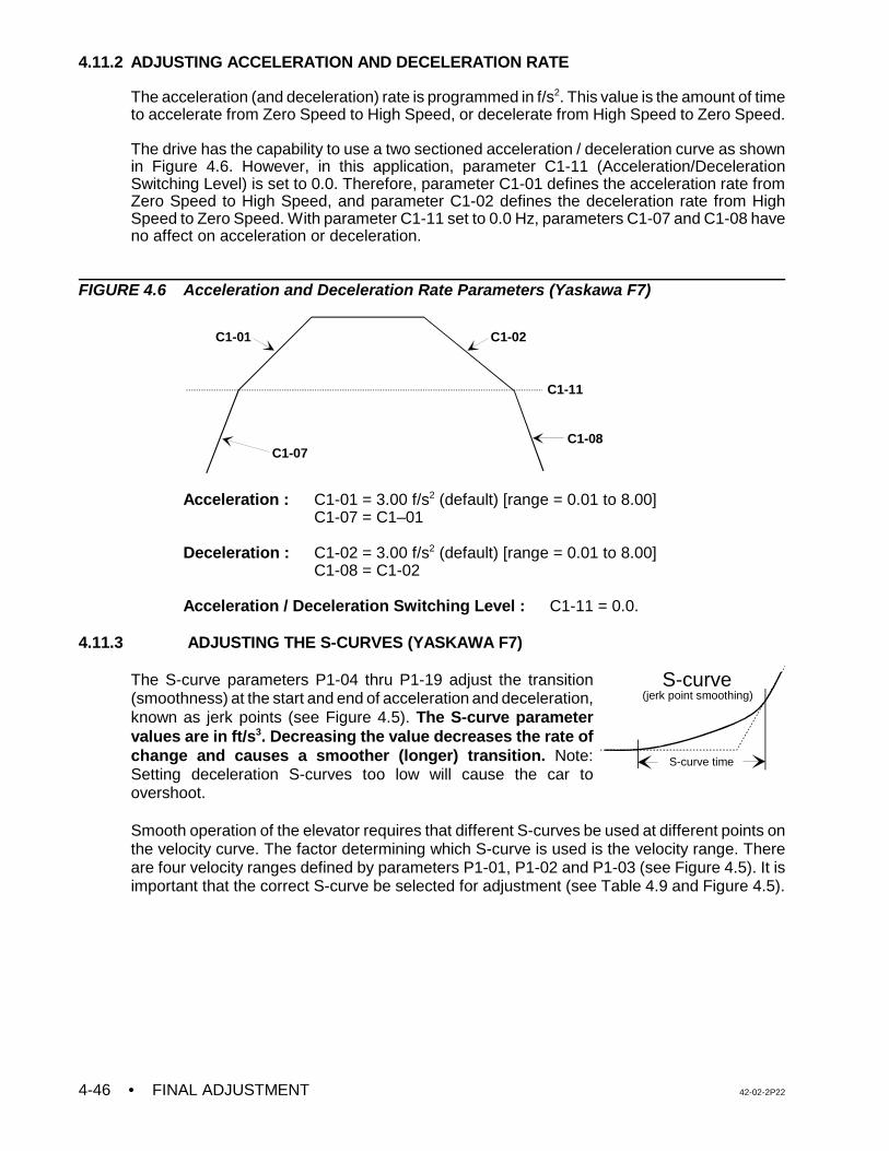
• FINAL ADJUSTMENT 42-02-2P224-46
C1-07
C1-01 C1-02
C1-08
C1-11
S-curve time
(jerk point smoothing)S-curve
4.11.2 ADJUSTING ACCELERATION AND DECELERATION RATE
The acceleration (and deceleration) rate is programmed in f/s2. This value is the amount of timeto accelerate from Zero Speed to High Speed, or decelerate from High Speed to Zero Speed.
The drive has the capability to use a two sectioned acceleration / deceleration curve as shownin Figure 4.6. However, in this application, parameter C1-11 (Acceleration/DecelerationSwitching Level) is set to 0.0. Therefore, parameter C1-01 defines the acceleration rate fromZero Speed to High Speed, and parameter C1-02 defines the deceleration rate from HighSpeed to Zero Speed. With parameter C1-11 set to 0.0 Hz, parameters C1-07 and C1-08 haveno affect on acceleration or deceleration.
FIGURE 4.6 Acceleration and Deceleration Rate Parameters (Yaskawa F7)
Acceleration : C1-01 = 3.00 f/s2 (default) [range = 0.01 to 8.00]C1-07 = C1–01
Deceleration : C1-02 = 3.00 f/s2 (default) [range = 0.01 to 8.00]C1-08 = C1-02
Acceleration / Deceleration Switching Level : C1-11 = 0.0.
4.11.3 ADJUSTING THE S-CURVES (YASKAWA F7)
The S-curve parameters P1-04 thru P1-19 adjust the transition(smoothness) at the start and end of acceleration and deceleration,known as jerk points (see Figure 4.5). The S-curve parametervalues are in ft/s3. Decreasing the value decreases the rate ofchange and causes a smoother (longer) transition. Note:Setting deceleration S-curves too low will cause the car toovershoot.
Smooth operation of the elevator requires that different S-curves be used at different points onthe velocity curve. The factor determining which S-curve is used is the velocity range. Thereare four velocity ranges defined by parameters P1-01, P1-02 and P1-03 (see Figure 4.5). It isimportant that the correct S-curve be selected for adjustment (see Table 4.9 and Figure 4.5).
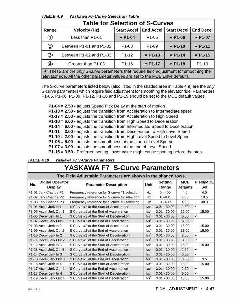
42-02-2P22 FINAL ADJUSTMENT • 4-47
TABLE 4.9 Yaskawa F7-Curve Selection Table
Table for Selection of S-CurvesRange Velocity (Hz) Start Accel End Accel Start Decel End Decel
Î Less than P1-01 w P1-04 P1-05 w P1-06 w P1-07
Ï Between P1-01 and P1-02 P1-08 P1-09 w P1-10 w P1-11
Ð Between P1-02 and P1-03 P1-12 w P1-13 w P1-14 w P1-15
Ñ Greater than P1-03 P1-16 w P1-17 w P1-18 P1-19
w These are the only S-curve parameters that require field adjustment for smoothing theelevator ride. All the other parameter values are set to the MCE Drive defaults.
The S-curve parameters listed below (also listed in the shaded area in Table 4.9) are the onlyS-curve parameters which require field adjustment for smoothing the elevator ride. ParametersP1-05, P1-08, P1-09, P1-12, P1-16 and P1-19 should be set to the MCE default values.
P1-04 = 2.50 - adjusts Speed Pick Delay at the start of motionP1-13 = 2.50 - adjusts the transition from Acceleration to Intermediate speedP1-17 = 2.50 - adjusts the transition from Acceleration to High SpeedP1-18 = 6.00 - adjusts the transition from High Speed to DecelerationP1-14 = 6.00 - adjusts the transition from Intermediate Speed to DecelerationP1-11 = 3.00 - adjusts the transition from Deceleration to High Level SpeedP1-10 = 2.00 - adjusts the transition from High Level Speed to Level SpeedP1-06 = 5.00 - adjusts the smoothness at the start of Level SpeedP1-07 = 3.00 - adjusts the smoothness at the end of Level SpeedP1-15 = 3.50 - Preferred setting, lower value might cause spotting before the stop.
TABLE 4.10 Yaskawa F7 S-Curve Parameters
YASKAWA F7 S-Curve Parameters
The Field Adjustable Parameters are shown in the shaded rows.
No.Digital Operator
DisplayParameter Description Unit
SettingRange
MCEDefaults
Field/MCESet
P1-01 Jerk Change P1 Frequency reference for S curve #1 selection Hz 0 - 400 4.0 4.0P1-02 Jerk Change P2 Frequency reference for S curve #2 selection Hz 0 -400 10.5 10.5P1-03 Jerk Change P3 Frequency reference for S curve #3 selecting Hz 0 - 400 48.0 48.0P1-04 Accel Jerk In 1 S Curve #1 at the Start of Acceleration f/s3 0.01 - 30.00 2.50 u
P1-05 Accel Jerk Out 1 S Curve #1 at the End of Acceleration f/s3 0.01 - 30.00 15.00 15.00P1-06 Decel Jerk In 1 S Curve #1 at the Start of Deceleration f/s3 0.01 - 30.00 5.00 u
P1-07 Decel Jerk Out 1 S Curve #1 at the End of Deceleration f/s3 0.01 - 30.00 3.00 u
P1-08 Accel Jerk In 2 S Curve #2 at the Start of Acceleration f/s3 0.01 - 30.00 15.00 15.00P1-09 Accel Jerk Out 2 S Curve #2 at the End of Acceleration f/s3 0.01 - 30.00 15.00 15.00P1-10 Decel Jerk In 2 S Curve #2 at the Start of Deceleration f/s3 0.01 - 30.00 2.00 u
P1-11 Decel Jerk Out 2 S Curve #2 at the End of Deceleration f/s3 0.01 - 30.00 3.00 u
P1-12 Accel Jerk In 3 S Curve #3 at the Start of Acceleration f/s3 0.01 - 30.00 15.00 15.00P1-13 Accel Jerk Out 3 S Curve #3 at the End of Acceleration f/s3 0.01 - 30.00 2.50 u
P1-14 Decel Jerk In 3 S Curve #3 at the Start of Deceleration f/s3 0.01 - 30.00 6.00 u
P1-15 Decel Jerk Out 3 S Curve #3 at the End of Deceleration f/s3 0.01 - 30.00 3.50 3.5P1-16 Accel Jerk In 4 S Curve #4 at the Start of Acceleration f/s3 0.01 - 30.00 15.00 15.00P1-17 Accel Jerk Out 4 S Curve #4 at the End of Acceleration f/s3 0.01 - 30.00 2.50 u
P1-18 Decel Jerk In 4 S Curve #4 at the Start of Deceleration f/s3 0.01 - 30.00 6.00 u
P1-19 Decel Jerk Out 4 S Curve #4 at the End of Deceleration f/s3 0.01 - 30.00 15.00 15.00
• FINAL ADJUSTMENT 42-02-2P224-48
The output response of the drive can be seen on an oscilloscope, when the car is running, bylooking at the voltage between terminals AM (Output Frequency) and AC (Com) on the driveterminals. The input can be seen at terminal FM (Speed Reference) and AC (Com). These twosignals are 0 -10VDC.
The High Level speed (D1-03), Level speed (L1-05), Deceleration time (C1-02) and S-curveparameters (P1-11, P1-10, P1-06, P1-07) should be adjusted for correct approach to the floor.
The Acceleration time (C1-01), and the S-curve parameters (P1-04 and P1-17) can be adjustedfor smooth starting and transition to High Speed. This will be addressed in the final adjustmentsection.
4.12 FINAL ADJUSTMENTS (YASKAWA F7)
For controllers with the G5 / GPD515 AC Drive, see Sections 4.2 thru 4.4 and 4.17.For controllers with the MagneTek HPV 900 AC Drive, see Sections 4.5 thru 4.7 and 4.17.For controllers with the TORQMAX F4 AC Drive, see Sections 4.8 thru 4.10 and 4.17.For controllers with the TORQMAX F5 AC Drive, see Sections 4.14 thru 4.16 and 4.17.
4.12.1 FINAL PREPARATION FOR RUNNING ON AUTOMATIC OPERATION (YASKAWA F7)
a. Temporarily take the car off of Inspection operation. If the LCD display does not showTEST MODE, see what message is being displayed and correct the problem. Forexample, if the indicators show that the car is on Fire Service Phase 1, a jumper mustbe connected between terminal 2 on the back plate and terminal 38 on the SC-SB2Kboard in order to run the car on Normal Operation. Remove the jumper once the FireService input is brought into the controller. Place the car back on Inspection.
b. Move the car to the bottom terminal landing. Check to see if the DZ relay is picked. Ifnot, move the car on Inspection to place it in the Door Zone.
4.12.2 SWITCHING TO AUTOMATIC OPERATION (YASKAWA F7)
Place the Relay Panel Inspection switch in the OFF position. If the car is not at a landing it willmove to a landing. If the car is at a landing but not in the door zone, relays L and either LU orLD should pick and the car should perform a relevel. If the relevel in not successful, check thefollowing:
C If the brake picks and the car is trying to level but is not able to, it may be necessary toadjust the Level Speed parameter (D1-05) on the Yaskawa F7 AC Drive to get the carto move.
C If relays L and LD are picked, but the brake and other relays are not, the down directionlimit switch may be preventing the leveling down operation.
C If the car is trying to level, it will not leave the landing for a call until the leveling iscomplete. Move the limit switch if necessary.
The Status Indicator lights should now display the indication for Independent Service operation.At this time the Position Indicator should match the actual car location. Note that all of thePosition Indicators and direction arrows are conveniently displayed on the controller. All thecalls are also displayed on the controller.
42-02-2P22 FINAL ADJUSTMENT • 4-49
NOTE: It is very important that the drive parameters only be changed when the caris stopped and the elevator is on Inspection or Test operation so that thereis no demand. To change a drive parameter, the Programming mode hasto be accessed. When the drive is in Programming mode it will not function.The drive has to be in Operation mode to run the elevator.
NOTE: The active speed will show on the drive key pad corresponding to thesetting of the D parameters.
4.12.3 BRAKE ADJUSTMENT FOR 125% LOAD (YASKAWA F7)
Put the car on Inspection at the bottom landing. Put 2/3 of a contract load in the car. Beginadding weights in 50 or 100 pound increments and move the car up and down on Inspectioneach time. Adjust the brake tension to stop and hold 125% of a contract load by tripping a stopswitch open while running down on Inspection. Hold the DOWN button in while tripping openthe stop switch (preferably on the Inspection station). KEEP THE CAR NEAR THE BOTTOMAS IT IS LIKELY TO SLIDE THROUGH THE BRAKE ONTO THE BUFFERS. If the VFAC DriveUnit trips off when the car is going down, but not while it is going up, refer to the manual for theVFAC Drive Unit and look up the failure indicated on the Drive display. If an over-voltage faultis indicated, there may be a problem in the regeneration (or braking) resistors, the brakingmodule (if one is provided). If this problem cannot be solved, call MCE Technical Support.Remove all test weights from the car.
4.12.4 BRINGING THE CAR UP TO HIGH SPEED (YASKAWA F7)
a. Verify that all the steps described in Sections 4.1 and 4.11 regarding the adjustmentsand specifically the drive parameters are complete.
b. Register a car call one floor above the car. The High speed relay (H) should pick andthe drive keypad should read 50% of contract speed as the car attempts to start. If thecar runs normally, commence multi-floor runs and slowly increase the High speedparameter (D1-02) until contract speed is achieved.
c. The Position Indicator will step at the slowdown distance from the next floor. Afterstepping occurs, High speed is dropped and the car should rapidly decelerate to HighLevel speed. Reduce the High Level speed parameter (D1-03 ) so that the car runs atabout 10 - 20 fpm or at a reasonable speed (use your personal judgment). Six inchesbefore the floor at which the car is to stop, High Level speed is dropped and the cardecelerates to Level speed. The Level speed can be adjusted using parameter D1-05so that the car levels into the floor and stops. Level speed should be 7 - 12 fpm, or areasonable leveling speed (use personal judgement). If the car re-levels frequently onceLevel speed is adjusted satisfactorily, spread apart the LU and LD sensors or switchesin the landing system to provide enough Dead Zone.
d. Adjust the SPD (Speed Pick Delay) trimpot by first turning it far enough clockwise sothat the empty car rolls back in the direction of the counterweight (if it can). Then adjustSPD so that the brake is fully picked just as the motor first moves. The goal is to delaylong enough to avoid moving the motor before the brake is fully lifted, but not so longas to allow the car to roll back.
e. Run the car again and verify that the car will start, accelerate, decelerate and run atHigh Level and Level speeds into the floor and stop. Place calls for all of the landings.Verify that all of the calls work. Verify the operation and placement of all vanes ormagnets and vane or magnet switches and verify that the car steps the Position
• FINAL ADJUSTMENT 42-02-2P224-50
NOTE: To observe the commanded speed and the drive output with anoscilloscope or a chart recorder, monitor drive terminals FM and AM withrespect to AC. These are 0 -10 VDC signals. Take all necessaryprecautions while measuring the voltage signals.
CAUTION: Most oscilloscopes have a grounding pin on their power plug. Werecommend defeating the grounding pin with one of the commonlyavailable ground isolation adapter plugs so that the case of theoscilloscope is not at ground potential, but at whatever potential thenegative probe lead is connected to. TREAT THE CASE OF THEOSCILLOSCOPE AS A LETHAL SHOCK HAZARD, DEPENDINGON WHERE THE NEGATIVE PROBE IS CONNECTED. Thisrecommendation is being made because the ground potential on thegrounding pin of the power outlet may not be the same as thecontroller cabinet ground. If it is not, substantial ground loop currentmay flow between the negative probe and the power plug groundingpin which can ruin the oscilloscope.
Indicators correctly. The slowdown distance for the elevator is measured from the pointwhere the STU sensor (or STD sensor, if going down) is activated by a metal vane ormagnetic strip to the position where the car is stopped at the floor with the DZ sensorcentered on the leveling target with LU or LD sensors not engaged.
The slowdown distance was chosen to give a reasonable deceleration rate. Continueto make two-floor runs and slowly increase High speed until Contract Speed is reached.It may be necessary to adjust the Deceleration rate parameters(C1-02 and C1-08) toget the car to approach the floor correctly as the car speed increases. Adjust theAcceleration rate parameters(C1-01 and C1-07) until the desired acceleration isachieved. Several runs may be required to obtain optimum acceleration. Theacceleration rate should be about the same as the deceleration rate.
f. If the job is a modernization, contract speed should correspond to a VFAC Drive outputfrequency of 60 Hz (± 8 Hz). The frequency may vary with direction and load. Arrangethe VFAC Drive Unit to display the output frequency to verify this.
g. To achieve a proper start, without rollback (or snapping away from the floor), a variabledelay in the application of the speed signal has been provided by adjusting trimpot SPD(Speed Pick Delay). Trimpot SPD must be adjusted to let the brake just clear the brakedrum before attempting to accelerate the car. Do this with an empty car. The correctsetting will be obvious by watching the Drive sheave. This was adjusted previously;however, check trimpot SPD again and make adjustments if necessary. The responseof the car can be monitored using an oscilloscope by measuring the voltage on the driveterminals FM and AM with respect to AC. These signals are 0 -10 volt. Terminal FM isprogrammed for the drive input speed reference and terminal AM is programmed for thedrive output frequency.
42-02-2P22 FINAL ADJUSTMENT • 4-51
NOTE: If the job has Intermediate Speed (SHR Relay), first adjust the multi-floorruns. Then make one floor runs and adjust parameter D1-07 to reach thecorrect intermediate speed. Do not change any other parameter exceptP1-13 or P1-14, if required, as described in Figure 4.6
For flux vector applications only: To improve the car's response the following driveparameters can be adjusted as described below, provided that the Motor data slipparameter (E2-02) and Motor No load current ( E2-03) are set correctly.
1. ASR Proportional Gain 1, ( C5-01) - The ASR Proportional Gain 1 controls theresponse of the car to the speed command. Increasing C5-01 results in tightercontrol. A low value may result in a speed deviation error. A too high value mayresult in oscillation.
2. ASR Integral Time 1, ( C5-02) - The ASR Integral Time 1 adjusts the amount oftime for the drive to respond to a change in speed command. Response time isincreased when the C5–02 is decreased. However, the car may becomeunstable if the ASR Integral Time is set too low.
3. Parameters C5-03 ( ASR P Gain 2) , and C5-04 ( ASR Integral Time 2) are notused and must be set to the factory default values.
h. The car should be running well now, except possibly for the final stop. Since the speed
reference goes to zero when the car stops, the VFAC Drive Unit will cause the machineto stop electrically. Enough delay in the setting of the brake (BDD) will have to beprovided to allow the sheave to stop turning before setting the brake firmly on the brakedrum.
When the elevator slows down to leveling speed and travels to door zone, the speedcommand will drop to zero before the brake drops. This is adjustable by the BDD (BrakeDrop Delay) trimpot. For open loop applications, the car stop will be accomplished withinjection braking current supplied by the VFAC Drive Unit at the end of the run. Thestrength and duration of this DC braking current is programmable using parametersB2-02 and B2-04 on the VFAC Drive Unit and, to start with, should be set at 50 and 0.5respectively (50% current and 0.5 second duration). A sharper and stronger electricstop is provided by increasing B2-02 and a softer stop by decreasing B2-02. Theduration of the DC injection braking must be less than the dropout time of thecontactor(s) which disconnect the motor from the VFAC Drive Unit. This assumes thatthe contactor(s) will open under zero current conditions. For Flux Vector applications,DC injection braking is not required for stopping. All B2 parameters must be set to thefactory default settings.
With the method of providing an electric stop as indicated above, provide a delay indropping the brake by turning the BDD (Brake Drop Delay) trimpot clockwise. The ideais to hold the brake up long enough to allow the motor to be stopped electrically andthen drop the brake immediately the instant the motor has stopped.
If there is too long of a delay before dropping the brake, the control system will releaseits control of the motor and the motor will drift briefly in the direction of the load beforethe brake is forced to drop by the PT relay. The BDD trimpot controls the dropping ofthe brake through the BE relay. Move the LU and LD sensors or switches closertogether (or further apart) so the car stops at the same location, up or down. Then movethe floor (leveling) magnet strips or vanes so the car stops accurately at each floor.
• FINAL ADJUSTMENT 42-02-2P224-52
i. The adjustment is almost complete. The acceleration rate setting on drive parameterC1-01 should be at least as great as the deceleration rate parameter C1-02, but itshould not be so high that it substantially exceeds the value of C1-02. Excessiveacceleration will probably cause the VFAC Drive Unit circuits to saturate and therefore,lose control of the car. Ideally, the slope of the acceleration in volts per second shouldbe equal to the slope of the deceleration. Note the present value of the C1-02parameter. Increase the value of C1-02 and run the car. Continue to increase the valueof C1-02 until the car overshoots the floor, requiring a relevel operation. Observe theresponse of the car to verify a stable releveling operation. Return the value of the C1-02parameter to its original value so that the approach to the floor is the same as before.After the car stops, check the empty car releveling operation by placing a jumperbetween terminals 18 and 26 to cause an up level after which the car will stop due topicking the LD (Down Level) switch. Remove the jumper from terminals 18 and 26 andthe car will level down against the counterweight. Make sure that it does not stall. If thecar stalls, you might have to increase the leveling speed.
4.12.5 LOAD TESTING (YASKAWA F7)
a. Begin adding test weights to the car in 100 or 200 pound increments all the way up tothe rated load. Observe the VFAC Drive Unit current on its display and check to see ifthere is an OC (Over Current) error indication as the car accelerates to full speed. If so,this indicates that the VFAC unit is being pushed close to its limits and may require oneor more of the following actions:
1. The requested acceleration rate may be excessive. Try reducing theacceleration rate by increasing parameter C1-01. The more time spent inacceleration, the lower the current demand.
2. A more gradual transition from acceleration to high speed may be made byincreasing drive parameter P1-17 for contact speed and P1-13 for intermediatespeed.
3. For Open loop applications - Adjust parameter C4-01(Torque CompensationGain) between 1.0 - 2.0. The maximum setting for this parameter is 2.5. Displaythe output current on the drive key pad in the Operation mode by pressing theup arrow twice. The drive keypad will display OUTPUT CURRENT U1-03= 0.0A.The F7 drive can provide 150% of its full load rated current for 1 minute. Runthe car and monitor the current on the drive keypad. If the motor is stalling butdoes not trip on OC faults, and if the value of the output current is morethan or close to the motor rated current but less than the maximum driveoutput current, check the motor winding configuration. Most elevatormotors are connected in Y configuration. But sometimes the DELTAconfiguration is used in order to pick the full load. The motor manufacturer’srecommendations must be taken into consideration. If the field survey data wasinaccurate, the Drive Unit may be undersized in relation to the motor. Call MCETechnical Support so that the job data can be reviewed.
For Flux Vector Applications -The Torque Compensation Gain parameter isnot available for flux vector applications. ASR Tuning (C5 parameters), asdescribed in Section 4.12.4 (g), can be adjusted to pick the full load.
42-02-2P22 FINAL ADJUSTMENT • 4-53
4. The motor may be underrated. It may be possible to get excellent results if thespeed is reduced slightly.
5. The elevator may be improperly counter weighted. This possibility should bethoroughly investigated.
6. Make a copy of the Table in Appendix J, Quick Reference for Yaskawa F7 DriveParameters and use the digital operator on the VFAC Drive Unit to look up andwrite down every parameter value as programmed in the unit. Use this as areference when calling MCE to review the data.
b. If there is a full load in the car and there is trouble slowing in the down direction, or ifthe VFAC Drive Unit is tripping off and there is an OV (over voltage) fault displayed, itmay mean that there is a problem with the regeneration (braking) resistors and/or thebraking unit (if supplied separately). Check for DC bus voltage. There are two methodsto check the DC bus voltage as described below:
1. Through the drive display: When the drive is in Operation mode, press the uparrow until Monitor function U1 is displayed, press enter and then use the uparrow to access the U1-07 (DC bus voltage). Then run the elevator and watchthe voltage reading.
2. Actual measurement of voltage: Use extreme care when measuring the DCvoltage across the drive power terminals (-) and (+ 2 or +3) under the aboveconditions.
If the bus voltage is 325 VDC (for a 230 VAC motor) or 650 VDC (for 460 VAC motor), and ifthere is no voltage measured across the braking resistors while the car is slowing with a fullload going down or empty car up, there may be a wiring problem, or a defective braking unit(if provided). Be sure to investigate this thoroughly. These resistors perform the task ofregulating car speed during a full load down or empty car up run (regeneration).
• FINAL ADJUSTMENT 42-02-2P224-54
WARNING: The following tests should be performed only by the qualified elevatorpersonnel skilled in final adjustment and inspections.
4.13 FINAL ELEVATOR INSPECTION PROCEDURE (YASKAWA F7)
For controllers with the G5 / GPD515 AC Drive, see Sections 4.2 thru 4.4 and 4.17.For controllers with the MagneTek HPV 900 AC Drive, see Sections 4.5 thru 4.7 and 4.17.For controllers with the TORQMAX F4 AC Drive, see Sections 4.8 thru 4.10 and 4.17.For controllers with the TORQMAX F5 AC Drive, see Sections 4.14 thru 4.16 and 4.17.
4.13.1 INSPECTION LEVELING OVER SPEED TEST (YASKAWA F7)
Note: Before performing tests 4.13.1 and 4.13.3, please remove the jumper between pinslabeled 2KBP1 and 2KBP2 on the SC-BASE board. Also rotate trimpots ILO, ETS and COSfully CW.
The SC-BASE board is equipped with an independent low speed monitoring system which canshut down the system if the car runs faster than a trimpot adjustable preset speed on Car TopInspection, Hoistway Access or Leveling operation. The monitoring system is active when theLeveling (LU1/LU2, LD1/LD2) relays are picked or when the Access/Inspection relay (IN1) isdropped out. The trimpot is labeled ILO (Inspection Leveling Overspeed) and is located on theSC-BASE board. The circuit looks at pulses coming from the speed sensor, sensing a magneton the motor shaft or brake drum, etc. Calibrate this circuit as follows:
a. Place the car on Inspection operation by placing the MACHINE ROOM INSPECTIONTRANSFER switch in the INSP position on the SC-SB2K.
b. Run the car on Inspection (up or down) and record the actual values for parameterD1-17 ________. D1-17 must be returned to the original value when this test iscomplete. Now, run the car on Inspection and adjust parameter D1-17 (Inspectionspeed) for the preferred maximum leveling speed (something below 150 fpm).
c. While running the car at the adjusted maximum leveling speed, slowly turn the ILOtrimpot CCW until the ILO1/ILO2 indicators turn ON. The car should come to animmediate stop and the MC-PCA LCD display should read “ILO Fault”. The ILO faultwill self reset in a moment.
d. Now set D1-17 to a lower value. Run the car on Inspection and increase the inspection
speed by increasing parameter D1-17 to show that this low speed safety monitor circuitwill trip at no higher than 150 fpm (or no higher than the desired maximum inspectionspeed). Check this in both directions. The overspeed monitor is now calibrated for lessthan 150 fpm for Access, Inspection and Leveling. Return parameter D1-17 to thevalue recorded in Step (b).
42-02-2P22 FINAL ADJUSTMENT • 4-55
4.13.2 TERMINAL SLOWDOWN LIMIT SWITCHES (YASKAWA F7)
Make sure that the terminal slowdown limit switches are working properly by doing thefollowing:
a. Place the TEST/NORMAL switch on the SC-SB2K board in the TEST position.
b. Disconnect and label the wires from terminals 71 ( STU) and 72 ( STD) on the SC-SB2K board.
c. Register calls for the terminal landings (top and bottom) from the controller. The carshould make a normal slowdown at both terminal landings except that there may be aslight relevel, which is okay. If the car goes more than an inch past the floor, move theslowdown limit until the approach is normal.
d. Reconnect the wires to terminals 71(STU) and 72 (STD) on the SC-SB2K board andreturn theTEST/NORMAL switch to the NORMAL position.
4.13.3 EMERGENCY TERMINAL LIMIT SWITCH MONITOR (YASKAWA F7)
All jobs under the requirements of ANSI A17.1 -2000 Articles 2.25.4.1. or 2.25.4.2 must havea means to ensure that the car speed is below contract speed after opening the associatedETS limit switches. The emergency terminal limit switch monitor performs this function.
The SC-BASE board carries out ETS monitoring functions via a speed senor that monitors amagnet installed on the motor shaft or brake drum as described in Section 2.2.3, Installing andWiring the Speed Sensor.
a. Make sure that shielded phone cable from the sensor to the SC-BASE board is securelyseated in the connectors at both ends and is also enclosed in conduit.
b. Check that the ETS trimpot is fully CW.
c. Record the value of parameter D1-02. Then, on a multi-floor run, adjust the speed ofthe car to 90% of the contract speed by adjusting the H speed (Drive parameter D1-02).
d. Remove both the Up Emergency and Terminal Limit Switch wires where they connectto the controller at terminals UETS1 and UETS2 on the SC-BASE board. Start the carat the bottom of the hoistway and while running the car in the up direction, slowly turnthe ETS trimpot CCW until the ETS indicator turns ON and the car stops. A faultmessage should be displayed on the MC-PCA board’s LCD display.
e. Press the fault reset push button on the SC-SB2K board to reset the fault.
f. Repeat (d) and (e) in the down direction with the wires from the DETS terminalsremoved. When the calibration is complete, reconnect the wires removed from theUETS and DETS terminals and return the H speed parameter D1.02 to its originalvalue.
g. Verify the calibration by turning OFF the inspection transfer switch. Place a call, andwith the car running at contract speed, remove the field wires from the UETS1 andUETS2 terminals on the SC-BASE board. The car must execute an emergencyslowdown. To restore normal operation, replace the wires and press the Fault Resetpushbutton on the SC-SB2K board. Repeat for terminals DETS1 and DETS2.
• FINAL ADJUSTMENT 42-02-2P224-56
NOTE: The car should be at the bottom landing with the TEST/ NORM switch onthe SC-SB2K board in the TEST position.
4.13.4 CONTRACT SPEED BUFFER TEST (YASKAWA F7):
4.13.4.1. COUNTER WEIGHT BUFFER TEST WITH EMPTY CAR GOING UP
To conduct the empty car buffer test going UP, a number of functions need to be bypassedusing jumpers. Follow the steps below:
a. On the SC-BASE board, install the jumper between pins 2KBP1 and 2KBP2. Also setthe ASME A17.1-2000 REDUNDANCY BYPASS to BYPASS ON (see section 5.6.5.1).
b. On the SC-BASE board, place the PFLT Bypass jumper in the ON position to bypassthe PLD ILO, ETS and contract overspeed fault functions.
c. Disconnect the Step Up (STU) input by removing the wire from terminal 72 on theSC-SB2K board. Tape the wire to prevent shorting.
d. Bypass the Emergency Terminal Up Limits, if provided, by placing jumpers betweenterminals 2 and UETS1 / UETS2 on the SC-BASE board.
e. Bypass the Up terminal slowdown and Up Normal Limit by placing jumpersbetween terminals 9 and 10 and terminals 10 and 11 on the SC-SB2K board.
f. Register a car call for the top terminal landing from the controller. The counterweightwill strike the buffer.
g. Put the elevator on Inspection and pick the down direction to move the car.
h. Remove the jumpers between terminals 9 and 10, and terminals 10 and 11 and
reconnect the wire to terminal 72 on the SC-SB2K board.
i. On the SC-BASE board, place the PFLT Bypass jumper in the OFF position to enablethe PLD ILO, ETS and contract overspeed fault functions.
j. On the SC-BASE board, remove the jumper between pins 2KBP1 and 2KBP2. Also setthe ASME A17.1-2000 REDUNDANCY BYPASS to BYPASS OFF (see Section5.6.5.1).
4.13.4.2 CAR BUFFER TEST WITH A FULL LOAD GOING DOWN
a. On the SC-BASE board, install the jumper between pins 2KBP1 and 2KBP2. Also setthe ASME A17.1-2000 REDUNDANCY BYPASS to BYPASS ON (see section 5.6.5.1).
b. On the SC-BASE board, place the PFLT Bypass jumper in the ON position to bypassthe PLD ILO, ETS and contract overspeed fault functions.
c. Disconnect the Step Down (STD) input by removing the wire from terminal 71 on theSC-SB2K board and tape the wire to prevent shorting.
42-02-2P22 FINAL ADJUSTMENT • 4-57
NOTE: If the governor overspeed trip point is less than 133% of contract speedthen perform the test as described below. If the trip point is greater than133% of contract speed then use other means to overspeed the car.
d. Bypass the Emergency Terminal Down Limits, if provided, by placing jumpersbetween terminals 2 and DETS1 / DETS2 on the SC-BASE board.
e. Bypass the Down terminal slowdown and Down Normal Limit by placing jumpersbetween terminals 9 and 12 and terminals 12 and 13 on the SC-SB2K board.
f. Position the elevator several floors above the bottom landing with a full load in the car.Then register a car call for the bottom landing. The car will strike the buffer.
g. Put the elevator on Inspection and pick the up direction to move the car.
h. On the SC-BASE board, place the PFLT Bypass jumper in the OFF position to enablethe PLD ILO, ETS and contract overspeed fault functions.
i. Remove the jumpers between terminals 9 and 12 and terminals 12 and 13 andreconnect the wire to terminal 71 on the SC-SB2K board.
j. On the SC-BASE board, remove the jumper between pins 2KBP1 and 2KBP2. Also set
the ASME A17.1-2000 REDUNDANCY BYPASS to BYPASS OFF (see Section5.6.5.1). Remove all of the jumpers installed in this section.
4.13.5 GOVERNOR AND CAR SAFETY TESTS (YASKAWA F7)
4.13.5.1 GOVERNOR ELECTRICAL OVERSPEED SWITCH TEST - Make sure that there areno jumpers between terminals 2 and 15. Trip open the electrical OVER SPEED switch contactmanually and verify that the main safety circuit drops out. Use which ever method is mostfamiliar to verify the actual electrical and mechanical tripping speeds.
4.13.5.2 GOVERNOR AND CAR SAFETY OVERSPEED TEST WITH FULL LOAD GOINGDOWN.
a. Move the fully loaded car to the top terminal landing. Record the value of parametersD1-02 (High Speed) ________ , E1-04(Maximum Output Frequency)_________ andO1-03 (Display Scaling) _________which are set to run the car on High speed. Theseparameters will be returned to their recorded values later in the adjustments.
b. Set parameter E1-04 = 80Hz, parameter D1-02 = governor tripping speed (fpm) and
parameter O1-03 - 1XXX00, where XXX = governor trip speed. This should run the carat governor tripping speed, if the motor is designed for 60Hz.
c. On the SC-BASE board, place the PFLT BYP jumper in the ON position to bypass thePLD ILO, ETS and contract overspeed fault functions.
d. If the HC-ACIF board is used in this controller, remove relays AS and ETL from theirsockets.
e. Connect a jumper between terminals EBS1 and EBS2 to bypass the governoroverspeed switch. Also, place a jumper between F7 Drive terminals SN and S3.
• FINAL ADJUSTMENT 42-02-2P224-58
f. In order to observe the loss of traction (when the safety mechanism sets) connect ajumper between terminal 16 on the SC-SB2K board and panel mount terminal 17 tobypass the safety plank (SOS) switch.
g. Turn the power ON and verify that controller is functional.
h. On the SC-BASE board, install the jumper between pins 2KBP1 and 2KBP2. Also setthe ASME A17.1-2000 REDUNDANCY BYPASS to BYPASS ON (see section 5.6.5.1).
i. Register a car call in the down direction, but not for the bottom landing. The car shouldtravel at 133% of contract speed. The governor should trip and set the safety and stopthe car.
j. Put the car on Inspection.
k. Return parameters E1-04, D1-02 and O1-03 to their recorded values.
l. Reset the mechanical governor and inspect the hoist ropes to make sure they are in theproper grooves.
m. Move the car UP on Inspection to release the flexible guide clamp safety or release thecar safety by hand if it is a wedge clamp type.
n. Remove the jumper between terminals EBS1 and EBS2 which bypasses thegovernor overspeed switch. Also remove the jumper between F7 Drive terminals SNand S3.
o. Remove the jumper from terminal 16 and panel mount terminal 17 whichbypasses the safety plank (SOS) switch).
p. Properly reinstall the relays AS and ETL on HC-ACIF board, if applicable. Removejumper between 2KBP1 and 2KBP2 on SC-BASE and set the ASME A17.1-2000REDUNDANCY BYPASS to BYPASS OFF (see Section 5.6.5.1).
q. On the SC-BASE board, place the PFLT BYP jumper in the OFF position to enable thePLD ILO, ETS and contract overspeed fault functions.
r. Put the car on Normal operation by taking the car off Inspection. After the elevator findsa floor, verify the operation of the elevator by registering calls and checking the speed.
4.13.6 PHASE LOSS DETECTION TESTS (YASKAWA F7)
The VFAC Drive Unit is programmed to detect a motor phase loss. Parameters L8-05 andL8-07 are enabled, which will activate the drive input and output phase loss detection.
To test for proper tripping of the drive output phase loss (connection between the drive andmotor), attempt to run the elevator on Inspection with one motor lead disconnected. The Driveshould trip off, dropping the RDY relay and the brake. The drive should display LF (Outputphase loss). A manual reset of the Drive on the HC-ACI board will be needed to return toNormal operation. Reconnect the motor lead and return the controls to Normal operation.
If input phase loss is required, disconnect any one of the three legs of the three phase MCEcontroller. When either L1 or L2 is removed the drive will not function because the drive’scontrol supply comes from L1 and L2. If either L2 or L3 is removed then the MCE controller will
42-02-2P22 FINAL ADJUSTMENT • 4-59
WARNING: Before the Elevator can be turned over to normal use, it is veryimportant that no safety circuit is bypassed. The items to be checkedinclude, but are not limited to:
* Check that the hierarchy of the inspection inputs is correct. Car top inspectionmust take priority over in car, hoistway access and machine room inspectionmodes. In car must take precedence over hoistway access and machine roominspection. Hoistway access must take priority over machine room inspection.
* Relay FLT on HC-ACI board and relays AS and ETL on the HC-ACIF board (ifprovided) must be installed properly in their sockets.
* No jumper between 2KBP1 and 2KBP2 on SC-BASE(R) * No jumpers between terminals 2 and UETS1/2 or DETS1/2.* No jumper between terminals 2 and 15 (SC-SB2K).* No jumper between terminals 2 and 9 (SC-SB2K)* No jumper between terminals 9 and 10 or 12 (SC-SB2K).* No jumper between terminals 10 and 11 (SC-SB2K).* No jumper between terminals 12 and 13 (SC-SB2K).* No jumper between terminals 16 and 17 (SC-SB2K).* No jumper between terminals EBS1 and EBS2.* Option ASME A17.1-2000 REDUNDANCY BYPASS to BYPASS OFF and F3
switch down (OFF) on MC-PCA. * Set the PFLT Bypass Jumper to the OFF position.* Drive parameter D1-02, E1-04 and O1-03 must be set to original value for High
speed and the jumper between F7 Drive terminals SN and S3 removed.* COS trimpot on the SC-BASE / SC-BASER board fully CW.
not function because the controller transformer is supplied by L2 and L3. If the controller anddrive are normal but the controller wiring is not done as described above and one of the inputpower wires is disconnected, then the drive will trip on fault PF (Input open phase) provided thatthe drive out current is greater than 30% of the drive full load current.
The adjustments and tests are complete. Now complete the A17.1 Code Compliant Functionsand Testing (Section 4.14) and fine tune any areas that may require touching up. Make surethat all of the appropriate data has been properly documented and that all of the jumpershave been removed before the car is returned to service.
• FINAL ADJUSTMENT 42-02-2P224-60
NOTE: In order to access the parameter values, review the use of the DigitalOperator in Section 3, Parameter Adjustments in the TORQMAX F5 DriveTechnical Manual.
CAUTION: Verify the critical drive parameter settings as described in Section3.6.2. Incorrect values for these parameters can cause erraticelevator operation.
CAUTION: It is very important that drive parameters only be changed when thecar is stopped and the elevator is on Inspection or Test operation.
4.14 EXPLANATION OF TORQMAX F5 DRIVE PARAMETERS AND S CURVES
For controllers with the G5 / GPD515 AC Drive, see Sections 4.2 thru 4.4 and 4.17.For controllers with the HPV 900 AC Drive, see Sections 4.5 thru 4.7 and 4.17.For controllers with the TORQMAX F4 AC Drive, see Sections 4.8 thru 4.10 and 4.17.For controllers with the Yaskawa F7 AC Drive, see Sections 4.11 thru 4.13 and 4.17.
Before attempting to bring the car up to contract speed, or making any adjustments, it isimportant to verify the following control parameters in the VFAC Drive Unit. It is very importantto become familiar with drive keypad operation to access the drive program.
4.14.1 SETTING THE SPEED LEVELS
The PTC Series M controller uses drive parameters for setting the five speed levels describedin Table 4.11 and Figure 4.7. The controller selects the desired speed using the TORQMAXF5 drive logic inputs. The Speed Command parameters should be set as shown in Table 4.11in preparation for running the elevator at High speed.
TABLE 4.11 TORQMAX F5 Drive Speed Levels
TORQMAX F5 Drive Speed Levels
SpeedSpeed/Driveparameter
Preferred setting in preparation for running the carat High speed.
Unit
Inspection InspectionSpeed (LF.43)
This speed can be increased to 66% of Contract Speedif required. ft/m
Level Level (LF.41) 2 to 5% of Contract Speed ft/m
High Level High Level (LF.44) 5 to 10% of Contract Speed ft/m
Intermediate Intermediate(LF.45)
42% of Contract Speed. This speed can be increased to91% if required, but must be less than Contract Speed.
ft/m
High High speed(LF.42)
50% of Contract Speed. This parameter will bechanged to Contract Speed during final adjustment.
ft/m
When parameter LF.86 is selected, the drive display indicates which speed is selected.
LF.86 Display Speed LF.86 Display Speed
0 or 7 No speed 4 Inspection Speed
2 Leveling Speed 5 High Leveling Speed
3 High Speed 6 Intermediate Speed
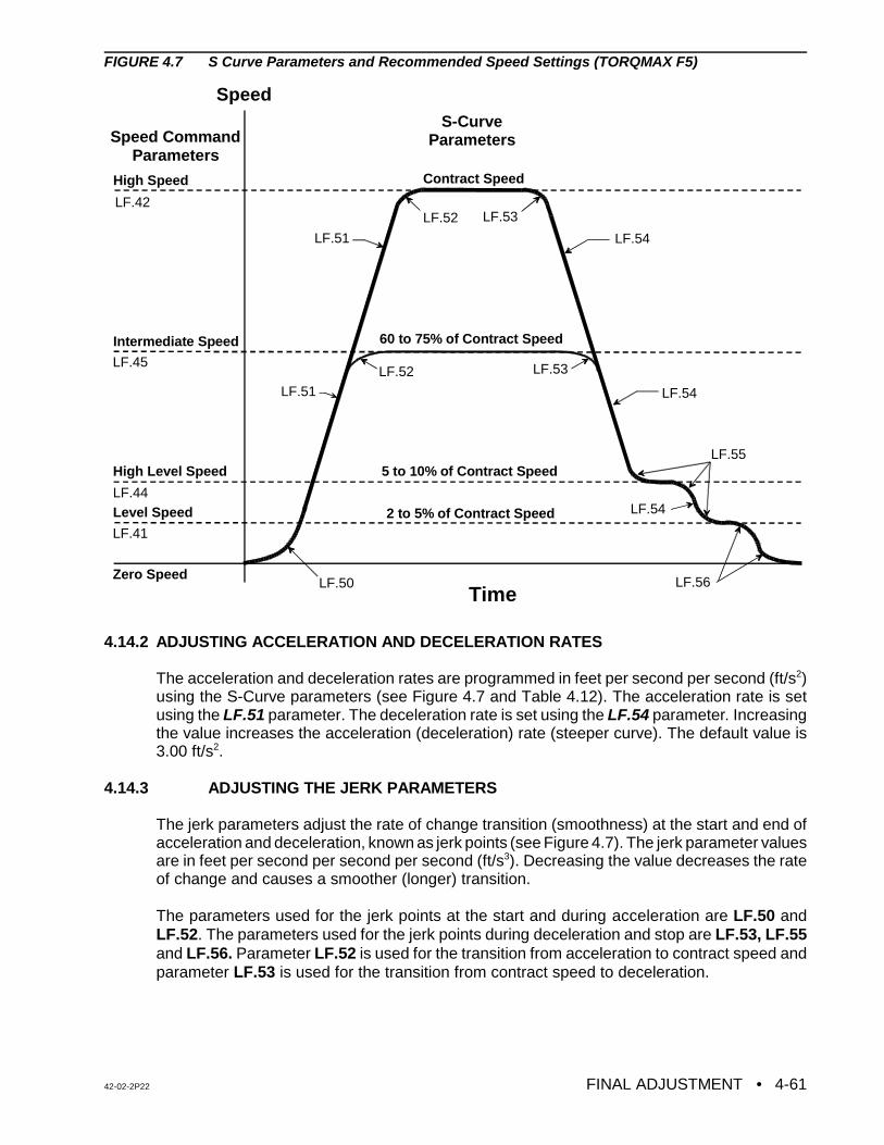
42-02-2P22 FINAL ADJUSTMENT • 4-61
Speed
TimeZero Speed
Level Speed
High Level Speed
Intermediate Speed
High Speed
LF.50
LF.51 LF.54
LF.56
LF.52
LF.52
LF.55
LF.53
Contract Speed
5 to 10% of Contract Speed
2 to 5% of Contract Speed
Speed CommandParameters
S-CurveParameters
LF.54
LF.54LF.51
60 to 75% of Contract Speed
LF.42
LF.45
LF.44
LF.41
LF.53
FIGURE 4.7 S Curve Parameters and Recommended Speed Settings (TORQMAX F5)
4.14.2 ADJUSTING ACCELERATION AND DECELERATION RATES
The acceleration and deceleration rates are programmed in feet per second per second (ft/s2)using the S-Curve parameters (see Figure 4.7 and Table 4.12). The acceleration rate is setusing the LF.51 parameter. The deceleration rate is set using the LF.54 parameter. Increasingthe value increases the acceleration (deceleration) rate (steeper curve). The default value is3.00 ft/s2.
4.14.3 ADJUSTING THE JERK PARAMETERS
The jerk parameters adjust the rate of change transition (smoothness) at the start and end ofacceleration and deceleration, known as jerk points (see Figure 4.7). The jerk parameter valuesare in feet per second per second per second (ft/s3). Decreasing the value decreases the rateof change and causes a smoother (longer) transition.
The parameters used for the jerk points at the start and during acceleration are LF.50 andLF.52. The parameters used for the jerk points during deceleration and stop are LF.53, LF.55and LF.56. Parameter LF.52 is used for the transition from acceleration to contract speed andparameter LF.53 is used for the transition from contract speed to deceleration.

• FINAL ADJUSTMENT 42-02-2P224-62
TABLE 4.12 TORQMAX F5 S Curve ParametersDrive
parameter Parameter Description Unit Setting Range DefaultSettings
FactorySettings
S-Curves (Profile 0)
0.LF.50 Start Jerk - used for the transition at the start ofacceleration ft/s3 0.30 - 32.00 3.00 3.00
0.LF.51 Acceleration rate ft/s2 0.30 - 12.00 3..50 3.50
0.LF.52 Acceleration Jerk - used for the transition fromacceleration to contract speed ft/s3 0.30 - 32.00 4.00 4.00
0.LF.53 Deceleration Jerk - used for the transition fromcontract speed to deceleration ft/s2 0.30 - 32.00 4.50 4.50
0.LF.54 Deceleration rate ft/s2 0.30 - 12.00 3.50 3.50
0.LF.55 Approach Jerk - used for the transitions at the endof deceleration ft/s3 0.30 - 32.00 2.50 2.50
LF.56 Stop Jerk - used for the final transitions fromleveling speed to zero speed ft/s3 off, 0.30 -32.00 1.00 1.50
Speed parametersLF.42 High speed ft/m 0 -100% * 0
LF.45 Intermediate speed ft/m 0 -91% * 0
LF.44 High Leveling speed ft/m 0 -25% * 0
LF.41 Leveling speed ft/m 0 -16% * 0
LF.43 Inspection speed ft/m 0 - 66% * 0*The speed setting range is described in percentage of the contract speed, but the actual entered valueof the speed is in FPM. The drive will not accept any speed, higher than the defined values.
The output response of the drive can be seen on an oscilloscope, when the car is running, bylooking at the voltage between terminals X2A.6 (Motor torque) and X2A.8 (Com) on theTORQMAX F5 drive. The input can be seen at terminal X2A.5 (Actual speed) and X2A.8(Com). The output signals are ±10V for X2A.6 and 0 - 10V for X2A.5.
The High Level speed LF.44, Level speed LF.41, Deceleration rate LF.54 and Jerk rateparameters LF.53 and LF.55 should be adjusted for correct approach to the floor.
The Acceleration, deceleration and the Jerk rates parameters can be adjusted for smoothstarting and transition to High speed. This will be addressed in the final adjustment section.
4.15 FINAL ADJUSTMENTS (TORQMAX F5)
For controllers with the G5 / GPD515 AC Drive, see Sections 4.2 thru 4.4 and 4.17.For controllers with the HPV 900 AC Drive, see Sections 4.5 thru 4.7 and 4.17.For controllers with the TORQMAX F4 AC Drive, see Sections 4.8 thru 4.10 and 4.17.For controllers with the Yaskawa F7 AC Drive, see Sections 4.11 thru 4.13 and 4.17.
4.15.1 FINAL PREPARATION FOR RUNNING ON AUTOMATIC OPERATION (TORQMAX F5)
a. Temporarily take the car off of Inspection operation. If the LED display does not showTEST MODE, see what message is being displayed and correct the problem. Forexample, if the indicators show that the car is on Fire Service Phase 1, a jumper mustbe connected between terminal 2 on the back plate and terminal 38 on the SC-SB2Kboard in order to run the car on Normal Operation. Remove the jumper once the FireService input is brought into the controller. Place the car back on Inspection.
42-02-2P22 FINAL ADJUSTMENT • 4-63
NOTE: It is very important that the drive parameters only be changed when the caris stopped and the elevator is on Inspection or Test operation so that thereis no demand.
b. Move the car to the bottom terminal landing. Check to see if the DZ relay is picked. Ifnot, move the car on Inspection to place it in the Door Zone.
4.15.2 SWITCHING TO AUTOMATIC OPERATION (TORQMAX F5)
Place the Relay Panel Inspection switch in the OFF position. If the car is not at a landing it willmove to a landing. If the car is at a landing but not in the door zone, relays L and either LU1/2or LD1/2 should pick and the car should perform a relevel. If the relevel in not successful, checkthe following:
C If the brake picks and the car is trying to level but is not able to, it may be necessary toadjust the Leveling Speed parameter (LF.41) on the TORQMAX F5 Drive to get the carto move.
C If relays L (on HC-ACI) and LD1/2 and LEX (on SC-SB2K) are picked, but the brakeand other relays are not, the down direction limit switch may be preventing the levelingdown operation.
C If the car is trying to level, it will not leave the landing for a call until the leveling iscomplete. Move the limit switch if necessary.
The Status Indicator lights should now display the indication for Independent Service operation.At this time the Position Indicator should match the actual car location. Note that all of thePosition Indicators and direction arrows are conveniently displayed on the controller. All thecalls are also displayed on the controller.
4.15.3 BRAKE ADJUSTMENT FOR 125% LOAD (TORQMAX F5)
Put the car on Inspection at the bottom landing. Put 2/3 of a contract load in the car. Beginadding weights in 50 or 100 pound increments and move the car up and down on Inspectioneach time. Adjust the brake tension to stop and hold 125% of a contract load by tripping a stopswitch open while running down on Inspection. Hold the DOWN button in while tripping openthe stop switch (preferably on the Inspection station). KEEP THE CAR NEAR THE BOTTOMAS IT IS LIKELY TO SLIDE THROUGH THE BRAKE ONTO THE BUFFERS. If the AC DriveUnit trips on a fault when the car is going down, but not while it is going up, refer to the manualfor the VFAC Drive Unit and look up the failure indicated on the Drive display. If the displayedfault is E.OP (over-voltage fault), there may be a problem in the regeneration (or braking)resistors, the braking module (if one is provided), or in the fuses that may be in series with thewires to the braking resistors.
If there is a problem lifting the load, Set parameter LF.38 = 0 (PWM = 8KHz). Then increasethe drive gain using parameters A.LF.31 KP Speed Accel: Proportional Gain and A.LF.32 KiSpeed Accel: Integral Gain. If this problem cannot be solved, call MCE Technical Support.
4.15.4 BRINGING THE CAR UP TO HIGH SPEED (TORQMAX F5)
a. Remove all test weights from the car. Verify that all the steps described in Sections 4.1and 4.14 regarding the adjustments and specifically the drive parameters are complete.
• FINAL ADJUSTMENT 42-02-2P224-64
NOTE: Drive gain adjustments - The default values for the gain parameters(A.LF.31 Kp Speed Accel: Proportional Gain and A.LF.32 Speed Accel:Integral Gain) may not be sufficient to run the car on High speed. It may benecessary to increase the value of these parameters.
NOTE: To observe the Actual speed and the motor torque with an oscilloscope ora chart recorder, monitor drive terminal X2A.5 and X2A.6 with respect toX2A.8. Take all necessary precautions while measuring the voltage signals.
b. Register a car call one floor above the car. The High speed relay (H) shouldpick and the drive keypad display should read 50% of Contract Speed as thecar attempts to start. If the car runs normally, commence multi-floor runs andslowly increase High speed by increasing parameter LF.42 until ContractSpeed is achieved. If there is a problem reaching Contract Speed, see thefollowing note.
c. At the slowdown distance from the next floor the Position Indicator will step. Afterstepping occurs, High speed is dropped and the car should rapidly decelerate to HighLevel speed. Reduce the High Level speed (LF.44) so that the car runs at about 10 -20 fpm or at a reasonable speed (use your personal judgment). Six inches before thefloor at which the car is to stop, High Level speed is dropped and the car shoulddecelerate to Level speed. The Level speed can be adjusted using parameter LF.41 sothat the car levels into the floor and stops. Level speed should be 7 - 12 fpm, or areasonable leveling speed (use personal judgement). If the car re-levels frequently onceLevel speed is adjusted satisfactorily, spread apart the LU and LD sensors or switchesin the landing system to provide enough Dead Zone.
d. Turn the Speed Pick Delay (SPD) trimpot fully CCW (fully OFF) and then set it 1/4 turnin the CW direction. The speed pick delay is achieved using the TORQMAX F5 driveparameter LF.70. Adjust LF.70 so that the brake is fully picked just as the motor firstmoves. The goal is to delay the speed command long enough to avoid moving themotor before the brake is fully lifted, but not so long as to allow the car to roll back.
e. Run the car again and verify that the car will start, accelerate, decelerate and run atHigh Level and Level speeds into the floor and stop. Place calls for all of the landings.Verify that all of the calls work. Verify the operation and placement of all vanes ormagnets and vane or magnet switches and verify that the car steps the PositionIndicators correctly. The slowdown distance for the elevator is measured from the pointwhere the STU sensor (or STD sensor, if going down) is activated by a metal vane ormagnetic strip to the position where the car is stopped at the floor with the DZ sensorcentered on the leveling target with LU or LD sensors not engaged.
This slowdown distance was chosen to give a reasonable deceleration rate. Continueto make two-floor runs and slowly increase High speed until Contract Speed is reached.It may be necessary to adjust the Deceleration rate (LF.54) and deceleration jerk rate(LF.55) to stop the car at the floor. Adjust the Acceleration rate parameter (LF.51) untilthe desired acceleration rate is achieved. Several runs may be required to obtainoptimum acceleration. The acceleration rate should be about the same as thedeceleration rate.
42-02-2P22 FINAL ADJUSTMENT • 4-65
CAUTION: Most oscilloscopes have a grounding pin on their power plug. Werecommend defeating the grounding pin with one of the commonlyavailable ground isolation adapter plugs so that the case of theoscilloscope is not at ground potential, but at whatever potential thenegative probe lead is connected to. TREAT THE CASE OF THEOSCILLOSCOPE AS A LETHAL SHOCK HAZARD, DEPENDINGON WHERE THE NEGATIVE PROBE IS CONNECTED. Thisrecommendation is being made because the ground potential on thegrounding pin of the power outlet may not be the same as thecontroller cabinet ground. If it is not, substantial ground loop currentmay flow between the negative probe and the power plug groundingpin which can ruin the oscilloscope
NOTE: During High speed, if the speed change-over can be felt in the car,increase parameter A.LF.33 Ki Speed Offset Accel and d.LF.33 Ki SpeedOffset Decel in steps of 100. This will help in achieving a smoothertransition.
f. To achieve a proper start, without rollback (or snapping away from the floor), a variabledelay in the application of the speed signal is provided using drive parameter LF.70Speed Pick Delay. Parameter LF.70 must be adjusted to let the brake just clear thebrake drum before attempting to accelerate the car. Do this with an empty car. Thecorrect setting will be obvious by watching the Drive sheave. This was adjustedpreviously; however, check parameter LF.70 again and make adjustments if necessary.The response of the car can be monitored using an oscilloscope by measuring thevoltage on the drive terminals X2A.5 and X2A.6 with respect to X2A.8. These signalsare ±10V and 0-10 V respectively. Terminal X2A.5 is assigned to the drive Actual speedreference and terminal X2A.6 is assigned to the drive motor torque.
g. The car should be running well now, except possibly for the final stop. Since the speedreference goes to zero when the car stops, the VFAC Drive Unit will cause the machineto stop electrically. Enough delay in the setting of the brake (BDD) will have to beprovided to allow the sheave to stop turning before setting the brake firmly on thesheave .
When the elevator slows down to leveling speed and travels to door zone, the speedcommand will drop to zero before the brake drops. This is adjustable using the BDD(Brake Drop Delay) trimpot. The idea is to hold the brake up long enough to allow themotor to be stopped electrically and then drop the brake immediately the instant themotor has stopped.
If there is too long of a delay before dropping the brake, the control system will releaseits control of the motor and the motor will drift briefly in the direction of the load beforethe brake is forced to drop by the PT relay. The BDD trimpot controls the dropping ofthe brake through the BE relay. Move the LU and LD sensors or switches closertogether (or further apart) so the car stops at the same location, up or down. Then movethe floor (leveling) magnet strips or vanes so the car stops accurately at each floor.
h. The adjustment is almost complete. The acceleration rate parameter setting should beat least as great as the deceleration rate parameter, but it should not be so high that itsubstantially exceeds the value of the deceleration rate parameter. Excessiveacceleration may cause the AC Drive circuits to saturate and thereby lose control of thecar. Ideally, the slope of the acceleration in volts per second should be equal to the
• FINAL ADJUSTMENT 42-02-2P224-66
slope of the deceleration. Note the present value of the deceleration parameter LF.54and run the car. Continue to decrease the value of LF.54 until the car overshoots thefloor, requiring a relevel operation. Observe the response of the car to verify a stablereleveling operation. Return the value of the LF.54 parameter to its original value sothat the approach to the floor is the same as before. After the car stops, check theempty car releveling operation by placing a jumper between terminals 18 and 26 tocause an up level after which the car will stop due to picking the LD (Down Level)switch. Remove the jumper from terminals 18 and 26 and the car will level down againstthe counterweight. Make sure that it does not stall. If the car stalls then you might haveto increase the leveling speed.
4.15.5 LOAD TESTING (TORQMAXF5)
a. Begin adding test weights to the car in 100 or 200 pound increments all the way up tothe rated load. Observe the AC Drive Unit current on its display LF.93 and check to seeif there is an E.OL or E.OL2 (Overload) error indication as the car accelerates to fullspeed. If so, it is an indication that the AC drive unit is being pushed close to its limitsand may require one or more of the following actions:
1. The requested acceleration rate may be excessive. Try reducing theacceleration rate by decreasing the LF.51 parameter. The lower the rate ofacceleration, the lower the current demand.
2. A more gradual transition from acceleration to high speed may be made bydecreasing the LF.52 (Acceleration Jerk) parameter.
3. Verify that LF.38 = 0 (PWM = 8KHz). The drive gains (parameters LF.31 andLF.32) may need to be increased.
4. The motor may be underrated. It may be possible to get excellent results if thespeed is reduced slightly.
5. The elevator may be improperly counter weighted. This possibility should bethoroughly investigated.
6. Make a copy of the table in Appendix D, Quick Reference for TORQMAX F5Drive Parameters. Use the digital operator on the Drive Unit to look up and writedown every parameter value as programmed in the unit. Use this as a referencewhen calling MCE to review the data.
b. If there is a full load in the car and there is trouble slowing in the down direction, or ifthe AC Drive Unit is tripping off and there is an E.OP (over voltage) fault displayed, itmay mean that there is a problem with the regeneration (braking) resistors and/or thebraking unit (if supplied separately). Verify the DC bus voltage. Two methods to checkthe DC bus voltage are described below:
1. Through the drive keypad display: When the drive is in Operation mode, accessparameter LF.95 (DC bus) voltage or parameter LF.96 (Peak DC bus) voltage.You can then run the elevator and watch the voltage reading,
2. Actual measurement of voltage: Use extreme care when measuring the DCvoltage across the drive power terminals (-) and (PA or ++) under the aboveconditions.
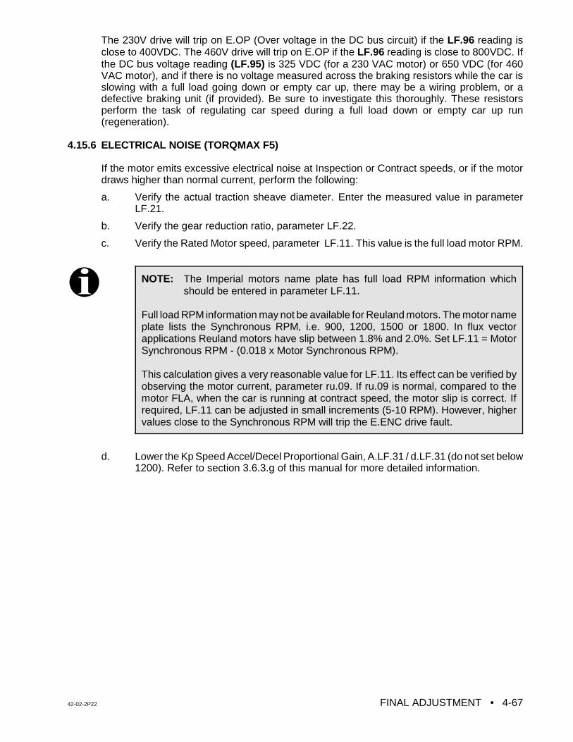
42-02-2P22 FINAL ADJUSTMENT • 4-67
NOTE: The Imperial motors name plate has full load RPM information whichshould be entered in parameter LF.11.
Full load RPM information may not be available for Reuland motors. The motor nameplate lists the Synchronous RPM, i.e. 900, 1200, 1500 or 1800. In flux vectorapplications Reuland motors have slip between 1.8% and 2.0%. Set LF.11 = MotorSynchronous RPM - (0.018 x Motor Synchronous RPM).
This calculation gives a very reasonable value for LF.11. Its effect can be verified byobserving the motor current, parameter ru.09. If ru.09 is normal, compared to themotor FLA, when the car is running at contract speed, the motor slip is correct. Ifrequired, LF.11 can be adjusted in small increments (5-10 RPM). However, highervalues close to the Synchronous RPM will trip the E.ENC drive fault.
The 230V drive will trip on E.OP (Over voltage in the DC bus circuit) if the LF.96 reading isclose to 400VDC. The 460V drive will trip on E.OP if the LF.96 reading is close to 800VDC. Ifthe DC bus voltage reading (LF.95) is 325 VDC (for a 230 VAC motor) or 650 VDC (for 460VAC motor), and if there is no voltage measured across the braking resistors while the car isslowing with a full load going down or empty car up, there may be a wiring problem, or adefective braking unit (if provided). Be sure to investigate this thoroughly. These resistorsperform the task of regulating car speed during a full load down or empty car up run(regeneration).
4.15.6 ELECTRICAL NOISE (TORQMAX F5)
If the motor emits excessive electrical noise at Inspection or Contract speeds, or if the motordraws higher than normal current, perform the following:
a. Verify the actual traction sheave diameter. Enter the measured value in parameterLF.21.
b. Verify the gear reduction ratio, parameter LF.22.
c. Verify the Rated Motor speed, parameter LF.11. This value is the full load motor RPM.
d. Lower the Kp Speed Accel/Decel Proportional Gain, A.LF.31 / d.LF.31 (do not set below1200). Refer to section 3.6.3.g of this manual for more detailed information.
• FINAL ADJUSTMENT 42-02-2P224-68
WARNING: The following tests should be performed only by qualified elevatorpersonnel skilled in final adjustment and inspections.
4.16 FINAL ELEVATOR INSPECTION PROCEDURE (TORQMAX F5)
For controllers with the G5 / GPD515 AC Drive, see Sections 4.2 thru 4.4 and 4.17.For controllers with the HPV 900 AC Drive, see Sections 4.5 thru 4.7 and 4.17.For controllers with the TORQMAX F4 AC Drive, see Sections 4.8 thru 4.10 and 4.17.For controllers with the Yaskawa F7 AC Drive, see Sections 4.11 thru 4.13 and 4.17.
4.16.1 INSPECTION LEVELING OVER SPEED TEST (TORQMAX F5)
Note: Before performing tests 4.16.1 and 4.16.3, please remove the jumper between pinslabeled 2KBP1 and 2KBP2 on the SC-BASE board. Also rotate trimpots ILO, ETS and COSfully CW.
The SC-BASE board is equipped with an independent low speed monitoring system which canshut down the system if the car runs faster than a trimpot adjustable preset speed on Car TopInspection, Hoistway Access or Leveling operation. The monitoring system is active when theLeveling (LU1/LU2, LD1/LD2) relays are picked or when the Access/Inspection relay (IN1) isdropped out. The trimpot is labeled ILO (Inspection Leveling Overspeed) and is located on theSC-BASE board. The circuit looks at pulses coming from the speed sensor, sensing a magneton the motor shaft or brake drum, etc. Calibrate this circuit as follows:
a. Place the car on Inspection operation by placing the MACHINE ROOM INSPECTIONTRANSFER switch in the INSP position on the SC-SB2K.
b. Run the car on Inspection (up or down) and record the actual measured car speed witha hand-held tachometer _____________. It must be returned to the original value whenthis test is complete. Now, run the car on Inspection and increase the Inspection speedparameter LF.43 until you are running at the speed that you want the system to trip offon inspection leveling overspeed (ILO - something below 150 fpm).
c. Run the car in the UP direction on Inspection while very slowly turning the ILO trimpotCCW until ILO1/ILO2 indicators just turn ON. After stopping, set LF.43 parameter to alower value. Run the car on Inspection and increase the inspection speed by increasingthe parameter LF.43 to verify that this low speed safety monitor circuit will trip at nohigher than 150 fpm (or no higher than the previous setting).
d. Place a call for a landing several floors away and as the car accelerates connect ajumper between test pin TP8 and TP2 (fused 2-bus). Relays LU1 and LU2 should pick.The system should make an emergency stop. Repeat for TP9 and TP2. Relays LD1and LD2 should pick. These test pins are located on the SC-SB2K board. Restorenormal operation by removing jumpers.
The circuit should trip in both directions. The inspection/leveling overspeed monitor is nowcalibrated for less than 150 fpm for Access, Inspection and Leveling. Turn the Inspection speedparameter LF.43 back to the value recorded in 4.16.1 (b).
42-02-2P22 FINAL ADJUSTMENT • 4-69
4.16.2 TERMINAL SLOWDOWN LIMIT SWITCHES (TORQMAX F5)
Make sure that the terminal slowdown limit switches are working properly by performing thefollowing steps:
a. Place the TEST/NORMAL switch on the SC-SB2K board in the TEST position.
b. Disconnect and label the wires from terminals 71 (STU) and 72 (STD) on the SC-SB2Kboard.
c. Register calls for the terminal landings (top and bottom) from the controller. The carshould make a normal slowdown at both terminal landings except that there may be aslight relevel, which is permitted. If the car goes more than an inch past the floor, movethe slowdown limit until the approach is quite close to normal.
d. Reconnect the wires to terminals 71(STU) and 72 (STD) on the SC-SB2K board andreturn the TEST/NORMAL switch to the NORMAL position.
4.16.3 EMERGENCY TERMINAL LIMIT SWITCH MONITOR (TORQMAX F5)
All jobs under the requirements of ANSI A17.1 - 2000 Articles 2.25.4.1. or 2.25.4.2 must havea means to insure that the car speed is below contract speed after opening the associatedETS limit switches. The emergency terminal limit switch monitor performs this function.
The SC-BASE board carries out ETS monitoring functions via a speed senor that monitors amagnet installed on the motor shaft or brake drum as described in Section 2.2.3, Installing andWiring the Speed Sensor.
a. Make sure that shielded phone cable from the sensor to the SC-BASE board is securelyseated in the connectors at both ends and is also enclosed in conduit.
b. On the SC-BASE board, verify that the ETS trimpot is fully CW.
c. Record the value of parameter LF.42. Then, on a multi-floor run, adjust the speed ofthe car to 90% of the contract speed by adjusting the High speed parameter LF. 42.
d. Remove both the Up Emergency and Terminal Limit Switch wires where they connectto the controller at terminals UETS1 and UETS2 on the SC-BASE board. Start the carat the bottom of the hoistway and while running the car in the up direction, slowly turnthe ETS trimpot CCW until the ETS indicator turns ON and the car stops. A faultmessage should be displayed on the MC-PCA board’s LCD display.
e. Press the fault reset push button on the SC-SB2K board to reset the fault.
f. Repeat (d) and (e) in the down direction with the wires from the DETS terminalsremoved. When the calibration is complete, reconnect the wires removed from theUETS and DETS terminals and return the High speed parameter LF.42 to its originalvalue.
g. Verify the calibration by turning OFF the inspection transfer switch. Place a call, andwith the car running at contract speed, remove the field wires from the UETS1 andUETS2 terminals on the SC-BASE board. The car must execute an emergencyslowdown. To restore normal operation, replace the wires and press the Fault Resetpushbutton on the SC-SB2K board. Repeat for terminals DETS1 and DETS2.
• FINAL ADJUSTMENT 42-02-2P224-70
NOTE: The car should be at the bottom landing with the TEST/ NORM switch onthe SC-SB2K board in the TEST position.
4.16.4 CONTRACT SPEED BUFFER TEST (TORQMAX F5):
4.16.4.1. COUNTER WEIGHT BUFFER TEST WITH EMPTY CAR GOING UP
To conduct the empty car buffer test going UP, a number of functions need to be bypassedusing jumpers. Follow the steps below:
a. On the SC-BASE board, install the jumper between pins 2KBP1 and 2KBP2. Also setthe ASME A17.1-2000 REDUNDANCY BYPASS to BYPASS ON (see section 5.6.5.1).
b. On the SC-BASE board, place the PFLT Bypass jumper in the ON position to bypassthe PLD ILO, ETS and contract overspeed fault functions.
c. Disconnect the Step Up (STU) input by removing the wire from terminal 72 on theSC-SB2K board. Tape the wire to prevent shorting.
d. Bypass the Emergency Terminal Up Limits, if provided, by placing jumpers betweenterminals 2 and UETS1 / UETS2 on the SC-BASE board.
e. Bypass the Up terminal slowdown and Up Normal Limit by placing jumpersbetween terminals 9 and 10 and terminals 10 and 11 on the SC-SB2K board.
f. Register a car call for the top terminal landing from the controller. The counterweightwill strike the buffer.
g. Put the elevator on Inspection and pick the down direction to move the car.
h. Remove the jumpers between terminals 9 and 10, and terminals 10 and 11 andreconnect the wire to terminal 72 on the SC-SB2K board.
i. On the SC-BASE board, place the PFLT Bypass jumper in the OFF position to enablethe PLD ILO, ETS and contract overspeed fault functions.
j. On the SC-BASE board, remove the jumper between pins 2KBP1 and 2KBP2. Also setthe ASME A17.1-2000 REDUNDANCY BYPASS to BYPASS OFF (see Section5.6.5.1).
4.16.4.2 CAR BUFFER TEST WITH A FULL LOAD GOING DOWN
a. On the SC-BASE board, install the jumper between pins 2KBP1 and 2KBP2. Also setthe ASME A17.1-2000 REDUNDANCY BYPASS to BYPASS ON (see section 5.6.5.1).
b. On the SC-BASE board, place the PFLT Bypass jumper in the ON position to bypassthe PLD ILO, ETS and contract overspeed fault functions.
c. Disconnect the Step Down (STD) input by removing the wire from terminal 71 on theSC-SB2K board and tape the wire to prevent shorting.
d. Bypass the Emergency Terminal Down Limits, if provided, by placing jumpersbetween terminals 2 and DETS1 / DETS2 on the SC-BASE board.
42-02-2P22 FINAL ADJUSTMENT • 4-71
e. Bypass the Down terminal slowdown and Down Normal Limit by placing jumpersbetween terminals 9 and 12 and terminals 12 and 13 on the SC-SB2K board.
f. Position the elevator several floors above the bottom landing with a full load in the car.Then register a car call for the bottom landing. The car will strike the buffer.
g. Put the elevator on Inspection and pick the up direction to move the car.
h. On the SC-BASE board, place the PFLT Bypass jumper in the OFF position to enablethe PLD ILO, ETS and contract overspeed fault functions.
i. Remove the jumpers between terminals 9 and 12 and terminals 12 and 13 andreconnect the wire to terminal 71 on the SC-SB2K board.
j. On the SC-BASE board, remove the jumper between pins 2KBP1 and 2KBP2. Also setthe ASME A17.1-2000 REDUNDANCY BYPASS to BYPASS OFF (see Section5.6.5.1). Remove all of the jumpers installed in this section.
4.16.5 GOVERNOR AND CAR SAFETY TESTS (TORQMAX F5)
4.16.5.1 GOVERNOR ELECTRICAL OVERSPEED SWITCH TEST - Make sure that there areno jumpers between terminals 2 and 15. Trip open the electrical OVER SPEED switch contactmanually and verify that the main safety circuit drops out. Use whichever method is mostfamiliar to verify the actual electrical and mechanical tripping speeds.
4.16.5.2 GOVERNOR AND CAR SAFETY OVERSPEED TEST WITH FULL LOAD GOINGDOWN.
a. Move the fully loaded car to the top terminal landing and turn the power OFF.
b. On the SC-BASE board, place the PFLT BYP jumper in the ON position to bypass thePLD ILO, ETS and contract overspeed fault functions.
c. If the HC-ACIF board is used in this controller, remove relays AS and ETL from their
sockets.
d. Connect a jumper between terminals EBS1 and EBS2 to bypass the governoroverspeed switch.
e. In order to observe the loss of traction (when the safety mechanism sets) connect a
jumper between terminal 16 on the SC-SB2K board and panel mount terminal 17 tobypass the safety plank (SOS) switch.
f. Turn the power ON and verify that the controller is functional.
g. On the SC-BASE board, install the jumper between pins 2KBP1 and 2KBP2. Also setthe ASME A17.1-2000 REDUNDANCY BYPASS to BYPASS ON (see section 5.6.5.1).
h. Make note of the value of drive parameters LF.20 and LF.42 . To run the car at 125 %of its original speed set parameters LF.20 and LF.42 to 125% of the original setting. Ifthe trip point is greater than 150%, skip steps (g), (h) and (i) and use other means toover speed the car.
i. Register a car call in the down direction, but not for the bottom landing. The car shouldtravel at 125% of Contract Speed. The governor should trip and set the safety and stopthe car.
• FINAL ADJUSTMENT 42-02-2P224-72
j. Put the car on Inspection.
k. Reset the AC drive parameters LF.20 and LF.42 to their original value (contract speedvalue).
l. Reset the mechanical governor and inspect the hoist ropes to make sure they are in theproper grooves.
m. Move the car UP on Inspection to release the flexible guide clamp safety or release thecar safety by hand if it is a wedge type clamp.
n. Remove the jumper between terminals EBS1 and EBS2 which bypasses thegovernor overspeed switch.
o. Remove the jumper from PC board terminal 16 and panel mount terminal 17which bypasses the safety plank (SOS) switch).
p. Reinstall relays AS and ETL on HC-ACIF board, if applicable. Also, remove jumperbetween SC-BASE terminals 2KBP1 and 2KBP2 and set the ASME A17.1-2000REDUNDANCY BYPASS to BYPASS OFF (see Section 5.6.5.1).
q. On the SC-BASE board, place the PFLT BYP jumper in the OFF position to enable thePLD ILO, ETS and contract overspeed fault functions.
r. Put the car on Normal operation by taking the car off Inspection. After the elevator findsa floor, verify the operation of the elevator by registering calls and checking the speed.
4.16.6 PHASE LOSS DETECTION TESTS (TORQMAX F5)
The VFAC Drive Unit is programmed to detect a motor phase loss. To test for proper trippingof the drive output phase loss (connection between the drive and motor), attempt to run theelevator on Inspection with one motor lead disconnected. The Drive should trip off, droppingthe RDY relay and the brake. The drive should display E.LC (no current flows to the motor). Amanual reset of the Drive on the HC-ACI board will be needed to return to Normal operation.Reconnect the motor lead and return the controls to Normal operation.
The drive adjustments and tests are complete. Now complete the A17.1 Code CompliantFunctions and Testing (Section 4.14) and fine tune any areas that may require touching up.Make sure that all of the appropriate data has been properly documented and that all ofthe jumpers have been removed before the car is returned to service.
42-02-2P22 FINAL ADJUSTMENT • 4-73
WARNING: Before the Elevator can be turned over to normal use, it is veryimportant to verify that no safety circuit is bypassed. The items to bechecked, include, but are not limited to:
* Verify that the hierarchy of the inspection inputs is correct. Car topinspection must take priority over in car, hoistway access and machineroom inspection modes. In car must take precedence over hoistwayaccess and machine room inspection. Hoistway access must take priorityover machine room inspection.
* Relays FLT on HC-ACI board and AS and ETL on the HC-ACIF board (ifprovided) must be installed properly in their sockets.
* No jumpers between terminals 2 and UET or DET.* No jumper between 2KBP1 and 2KBP2 on SC-BASE* No jumper between terminals 2 and 15 (SC-SB2K).* No jumper between terminals 4 and 9 (SC-SB2K).* No jumper between terminals 9 and 10 or 12 (SC-SB2K).* No jumper between terminals 10 and 11 (SC-SB2K).* No jumper between terminals 12 and 13 (SC-SB2K).* No jumper between terminals 16 and 17 (SC-SB2K).* No jumper between terminals EBS1 and EBS2.* Speed Command 9 and Overspeed Level parameters must be set to
original value for high speed.* Option ASME A17.1-2000 REDUNDANCY BYPASS is set to BYPASS
OFF and F3 switch down (OFF) on MC-PCA. * Set the PFLT Bypass Jumper to the OFF position.* Parameters LF.20 and LF.42 set to 100% of contract speed.* COS trimpot on the SC-BASE / SC-BASER board fully CW.
4.17 ASME A17.1 - 2000 CODE COMPLIANT FUNCTIONS AND TESTING
This section of the manual outlines the calibration and testing of the portion of the controlsystem used to meet the requirements of the ASME A17.1-2000 code. After completing theoverspeed test, test both the ascending car overspeed and unintended car movementprotection.
First, verify that the overspeed functions for ETS and ILO have been calibrated.
4.17.1 OVERSPEED CALIBRATION AND TESTING
Refer to one of the following sections:
• Section 4.4 for G5 / GPD515 drives,
• Section 4.7 for MagneTek HPV 900 drives,
• Section 4.10 for TORQMAX F4 drives
• Section 4.13 for Yaskawa F7 drives or
• Section 4.16 for TORQMAX F5 drives.
• FINAL ADJUSTMENT 42-02-2P224-74
4.17.2 ASCENDING CAR OVERSPEED PROTECTION
Prior to this test the governor overspeed switch velocity setting needs to be checked bywhatever means is normally used. The emergency brake must be installed and adjusted permanufacturer’s specifications. Note that it is critical for the Hollister-Whitney Rope Gripper, thatthe brake shoes are properly “arced-in” to conform with the curvature of the ropes (refer to theHollister-Whitney Rope Gripper instructions).
a. On the SC-BASE board, place a jumper between 2KBP1 and 2KBP2.
b. On MC-PCA board, place the F3 switch UP and set the ASME A17.1-2000
REDUNDANCY BYPASS to BYPASS ON (see Section 5.6.5.1).
c. On SC-SB2K board, place TEST/NORMAL switch in TEST position.
d. Run empty car to bottom landing and have a technician monitor car speed with a handoperated tachometer. With doors closed, use what ever method you are familiar withto overspeed the car in the up direction. As the car accelerates have the technician callout car speed so that the car can be stopped if the governor overspeed switch does notactivate when required.
e. Once the governor overspeed switch opens the Emergency Brake should immediately
apply and bring the car to a rapid stop.
f. To restore normal operation, reset GOV overspeed switch. Remove all jumpers andset the ASME A17.1-2000 REDUNDANCY BYPASS to BYPASS OFF (see Section5.6.5.1). Turn Inspection OFF and place TEST/NORMAL on NORMAL.
4.17.3 UNINTENDED CAR MOVEMENT PROTECTION
a. For safety, station a mechanic at the landing where the test is to be performed.
b. Bring the car to the mechanic and arrange to open both the car and hoistway doors.Place barricades in front of the open car and hoistway doors.
c. Meanwhile, back in the machine room, use whatever method you are familiar with toallow the car to drift away from the landing with doors open.
d. As the car moves away from the floor, observe that the emergency brake stops and
holds the car within 48" of floor level.
e. To restore normal operation, close and lock both the car and hoistway doors and thenpress and hold the Emergency Brake Reset pushbutton (SC-BASE board) until theemergency brake resets.
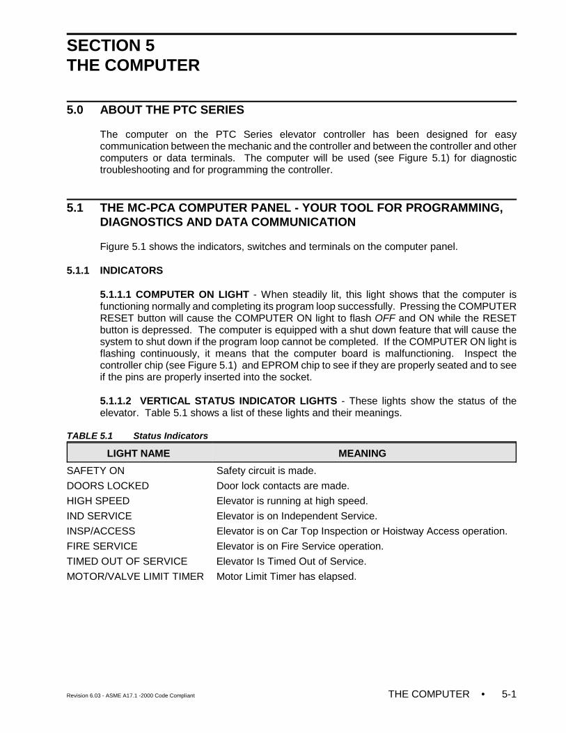
Revision 6.03 - ASME A17.1 -2000 Code Compliant THE COMPUTER • 5-1
SECTION 5THE COMPUTER
5.0 ABOUT THE PTC SERIES
The computer on the PTC Series elevator controller has been designed for easycommunication between the mechanic and the controller and between the controller and othercomputers or data terminals. The computer will be used (see Figure 5.1) for diagnostictroubleshooting and for programming the controller.
5.1 THE MC-PCA COMPUTER PANEL - YOUR TOOL FOR PROGRAMMING, DIAGNOSTICS AND DATA COMMUNICATION
Figure 5.1 shows the indicators, switches and terminals on the computer panel.
5.1.1 INDICATORS
5.1.1.1 COMPUTER ON LIGHT - When steadily lit, this light shows that the computer isfunctioning normally and completing its program loop successfully. Pressing the COMPUTERRESET button will cause the COMPUTER ON light to flash OFF and ON while the RESETbutton is depressed. The computer is equipped with a shut down feature that will cause thesystem to shut down if the program loop cannot be completed. If the COMPUTER ON light isflashing continuously, it means that the computer board is malfunctioning. Inspect thecontroller chip (see Figure 5.1) and EPROM chip to see if they are properly seated and to seeif the pins are properly inserted into the socket.
5.1.1.2 VERTICAL STATUS INDICATOR LIGHTS - These lights show the status of theelevator. Table 5.1 shows a list of these lights and their meanings.
TABLE 5.1 Status Indicators
LIGHT NAME MEANING
SAFETY ON Safety circuit is made.
DOORS LOCKED Door lock contacts are made.
HIGH SPEED Elevator is running at high speed.
IND SERVICE Elevator is on Independent Service.
INSP/ACCESS Elevator is on Car Top Inspection or Hoistway Access operation.
FIRE SERVICE Elevator is on Fire Service operation.
TIMED OUT OF SERVICE Elevator Is Timed Out of Service.
MOTOR/VALVE LIMIT TIMER Motor Limit Timer has elapsed.
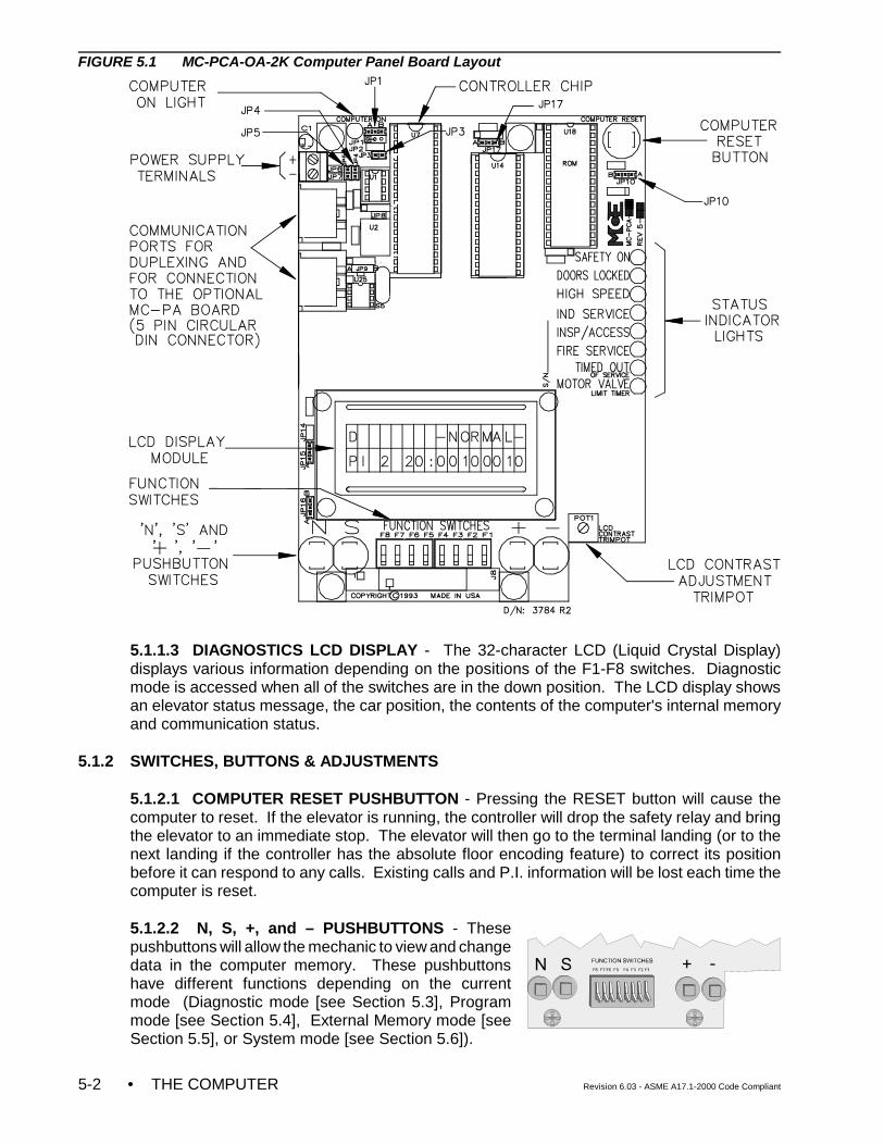
• THE COMPUTER Revision 6.03 - ASME A17.1-2000 Code Compliant5-2
FIGURE 5.1 MC-PCA-OA-2K Computer Panel Board Layout
5.1.1.3 DIAGNOSTICS LCD DISPLAY - The 32-character LCD (Liquid Crystal Display)displays various information depending on the positions of the F1-F8 switches. Diagnosticmode is accessed when all of the switches are in the down position. The LCD display showsan elevator status message, the car position, the contents of the computer's internal memoryand communication status.
5.1.2 SWITCHES, BUTTONS & ADJUSTMENTS
5.1.2.1 COMPUTER RESET PUSHBUTTON - Pressing the RESET button will cause thecomputer to reset. If the elevator is running, the controller will drop the safety relay and bringthe elevator to an immediate stop. The elevator will then go to the terminal landing (or to thenext landing if the controller has the absolute floor encoding feature) to correct its positionbefore it can respond to any calls. Existing calls and P.I. information will be lost each time thecomputer is reset.
5.1.2.2 N, S, +, and – PUSHBUTTONS - Thesepushbuttons will allow the mechanic to view and changedata in the computer memory. These pushbuttonshave different functions depending on the currentmode (Diagnostic mode [see Section 5.3], Programmode [see Section 5.4], External Memory mode [seeSection 5.5], or System mode [see Section 5.6]).
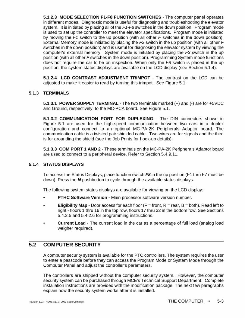
Revision 6.03 - ASME A17.1 -2000 Code Compliant THE COMPUTER • 5-3
5.1.2.3 MODE SELECTION F1-F8 FUNCTION SWITCHES - The computer panel operatesin different modes. Diagnostic mode is useful for diagnosing and troubleshooting the elevatorsystem. It is initiated by placing all of the F1-F8 switches in the down position. Program modeis used to set up the controller to meet the elevator specifications. Program mode is initiatedby moving the F1 switch to the up position (with all other F switches in the down position).External Memory mode is initiated by placing the F2 switch in the up position (with all other Fswitches in the down position) and is useful for diagnosing the elevator system by viewing thecomputer's external memory. System mode is initiated by placing the F3 switch in the upposition (with all other F switches in the down position). Programming System mode functionsdoes not require the car to be on inspection. When only the F8 switch is placed in the upposition, the system status displays are available on the LCD display (see Section 5.1.4).
5.1.2.4 LCD CONTRAST ADJUSTMENT TRIMPOT - The contrast on the LCD can beadjusted to make it easier to read by turning this trimpot. See Figure 5.1.
5.1.3 TERMINALS
5.1.3.1 POWER SUPPLY TERMINAL - The two terminals marked (+) and (-) are for +5VDCand Ground, respectively, to the MC-PCA board. See Figure 5.1.
5.1.3.2 COMMUNICATION PORT FOR DUPLEXING - The DIN connectors shown inFigure 5.1 are used for the high-speed communication between two cars in a duplexconfiguration and connect to an optional MC-PA-2K Peripherals Adaptor board. Thecommunication cable is a twisted pair shielded cable. Two wires are for signals and the thirdis for grounding the shield (see the Job Prints for hook-up details).
5.1.3.3 COM PORT 1 AND 2 - These terminals on the MC-PA-2K Peripherals Adaptor boardare used to connect to a peripheral device. Refer to Section 5.4.9.11.
5.1.4 STATUS DISPLAYS
To access the Status Displays, place function switch F8 in the up position (F1 thru F7 must bedown). Press the N pushbutton to cycle through the available status displays.
The following system status displays are available for viewing on the LCD display:
• PTHC Software Version - Main processor software version number.
• Eligibility Map - Door access for each floor (F = front, R = rear, B = both). Read left toright - floors 1 thru 16 in the top row, floors 17 thru 32 in the bottom row. See Sections5.4.2.5 and 5.4.2.6 for programming instructions.
• Current Load - The current load in the car as a percentage of full load (analog loadweigher required).
5.2 COMPUTER SECURITY
A computer security system is available for the PTC controllers. The system requires the userto enter a passcode before they can access the Program Mode or System Mode through theComputer Panel and adjust the controller’s parameters.
The controllers are shipped without the computer security system. However, the computersecurity system can be purchased through MCE's Technical Support Department. Completeinstallation instructions are provided with the modification package. The next few paragraphsexplain how the security system works after it is installed.
• THE COMPUTER Revision 6.03 - ASME A17.1-2000 Code Compliant5-4
PASSCODE REQUEST
PI 8 20:10001000
NOTE: This message is not related to ComputerSecurity. If the message on the LCD screenis “PASSCODE REQUEST,” it means that thePasscode Request Option has been activated and that a passcode isrequired in order to run the elevator on any mode of operation other thanInspection. See Section 5.6.2, Passcode Request Menu for more info.
Diagnostic mode
5.2.1 PASSWORD
There are two sections that are secured by an 8-digit, alpha-numeric code chosen by thecustomer, Program Mode and System Mode.
When either of these two sections is accessed, the LCDdisplay will show:
ENTER PASSWORD:
00000000
The mechanic must then enter the correct passcode to log into the system. Only then can thecomputer be used to program the controller.
The password is entered the same way and has the same code for both modes.
N Pushbutton Change the position of the cursor.+ Pushbutton Increment the current position by one.– Pushbutton Decrement the current position by one.S Pushbutton Check for a match
If an invalid code is entered, the operator will be prompted to re-enter the code. Once a validcode has been entered, access is granted to the programming options and the password willnot have to be reentered until the Password Timer expires.
5.3 DIAGNOSTIC MODE
MCE's PTC Elevator Controller Computer with On-Board Diagnostics is self-sufficient; externaldevices are not required when using the computer. The computer is generally the most reliablecomponent of the elevator control system and the On-Board Diagnostics were designed to aidin evaluating the status of the control system. The On-Board Diagnostics help to pinpoint thecause of elevator malfunctions.
5.3.1 GETTING INTO DIAGNOSTIC MODE
Diagnostic mode is initiated by placing the F1-F8 switches inthe down position. A description of the LCD display formatand the function of the N, S, +, and ! pushbuttons duringDiagnostic mode follows.
5.3.2 FUNCTION OF N PUSHBUTTON
The N pushbutton (see Figure 5.1) allows for the advancementof the computer memory address, which is displayed on thesecond line of the LCD. For example, in this display, pressingthe N pushbutton once will cause the 2 of the address 20 tobegin blinking. By continuing to press the N pushbutton, the 0 of the address 20 will begin to
NORMAL OPERATION
PI 8 20:10110011
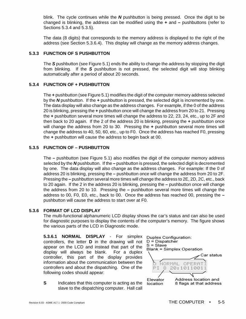
Revision 6.03 - ASME A17.1 -2000 Code Compliant THE COMPUTER • 5-5
blink. The cycle continues while the N pushbutton is being pressed. Once the digit to bechanged is blinking, the address can be modified using the + and – pushbuttons (refer toSections 5.3.4 and 5.3.5).
The data (8 digits) that corresponds to the memory address is displayed to the right of theaddress (see Section 5.3.6.4). This display will change as the memory address changes.
5.3.3 FUNCTION OF S PUSHBUTTON
The S pushbutton (see Figure 5.1) ends the ability to change the address by stopping the digitfrom blinking. If the S pushbutton is not pressed, the selected digit will stop blinkingautomatically after a period of about 20 seconds.
5.3.4 FUNCTION OF + PUSHBUTTON
The + pushbutton (see Figure 5.1) modifies the digit of the computer memory address selectedby the N pushbutton. If the + pushbutton is pressed, the selected digit is incremented by one.The data display will also change as the address changes. For example, if the 0 of the address20 is blinking, pressing the + pushbutton once will change the address from 20 to 21. Pressingthe + pushbutton several more times will change the address to 22, 23, 24, etc., up to 2F andthen back to 20 again. If the 2 of the address 20 is blinking, pressing the + pushbutton oncewill change the address from 20 to 30. Pressing the + pushbutton several more times willchange the address to 40, 50, 60, etc., up to F0. Once the address has reached F0, pressingthe + pushbutton will cause the address to begin back at 00.
5.3.5 FUNCTION OF – PUSHBUTTON
The – pushbutton (see Figure 5.1) also modifies the digit of the computer memory addressselected by the N pushbutton. If the – pushbutton is pressed, the selected digit is decrementedby one. The data display will also change as the address changes. For example: If the 0 ofaddress 20 is blinking, pressing the – pushbutton once will change the address from 20 to 2F.Pressing the – pushbutton several more times will change the address to 2E, 2D, 2C, etc., backto 20 again. If the 2 in the address 20 is blinking, pressing the – pushbutton once will changethe address from 20 to 10. Pressing the – pushbutton several more times will change theaddress to 00, F0, E0, etc., back to 00. Once the address has reached 00, pressing the –pushbutton will cause the address to start over at F0.
5.3.6 FORMAT OF LCD DISPLAY The multi-functional alphanumeric LCD display shows the car’s status and can also be usedfor diagnostic purposes to display the contents of the computer’s memory. The figure showsthe various parts of the LCD in Diagnostic mode.
5.3.6.1 NORMAL DISPLAY - For simplexcontrollers, the letter D in the drawing will notappear on the LCD and instead that part of thedisplay will always be blank. For a duplexcontroller, this part of the display providesinformation about the communication between thecontrollers and about the dispatching. One of thefollowing codes should appear:
S Indicates that this computer is acting as theslave to the dispatching computer. Hall call
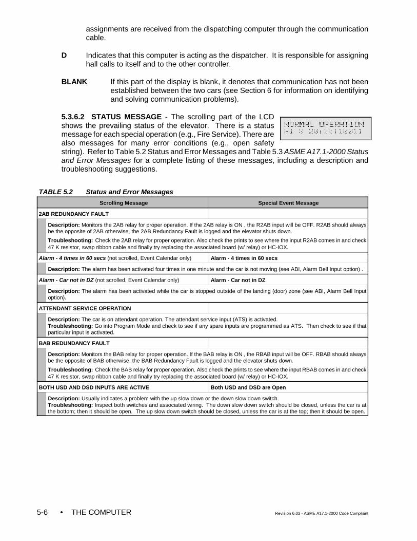
• THE COMPUTER Revision 6.03 - ASME A17.1-2000 Code Compliant5-6
assignments are received from the dispatching computer through the communicationcable.
D Indicates that this computer is acting as the dispatcher. It is responsible for assigninghall calls to itself and to the other controller.
BLANK If this part of the display is blank, it denotes that communication has not beenestablished between the two cars (see Section 6 for information on identifyingand solving communication problems).
5.3.6.2 STATUS MESSAGE - The scrolling part of the LCDshows the prevailing status of the elevator. There is a statusmessage for each special operation (e.g., Fire Service). There arealso messages for many error conditions (e.g., open safetystring). Refer to Table 5.2 Status and Error Messages and Table 5.3 ASME A17.1-2000 Statusand Error Messages for a complete listing of these messages, including a description andtroubleshooting suggestions.
TABLE 5.2 Status and Error Messages
Scrolling Message Special Event Message
2AB REDUNDANCY FAULT
Description: Monitors the 2AB relay for proper operation. If the 2AB relay is ON , the R2AB input will be OFF. R2AB should alwaysbe the opposite of 2AB otherwise, the 2AB Redundancy Fault is logged and the elevator shuts down.
Troubleshooting: Check the 2AB relay for proper operation. Also check the prints to see where the input R2AB comes in and check47 K resistor, swap ribbon cable and finally try replacing the associated board (w/ relay) or HC-IOX.
Alarm - 4 times in 60 secs (not scrolled, Event Calendar only) Alarm - 4 times in 60 secs
Description: The alarm has been activated four times in one minute and the car is not moving (see ABI, Alarm Bell Input option) .
Alarm - Car not in DZ (not scrolled, Event Calendar only) Alarm - Car not in DZ
Description: The alarm has been activated while the car is stopped outside of the landing (door) zone (see ABI, Alarm Bell Inputoption).
ATTENDANT SERVICE OPERATION
Description: The car is on attendant operation. The attendant service input (ATS) is activated.Troubleshooting: Go into Program Mode and check to see if any spare inputs are programmed as ATS. Then check to see if thatparticular input is activated.
BAB REDUNDANCY FAULT
Description: Monitors the BAB relay for proper operation. If the BAB relay is ON , the RBAB input will be OFF. RBAB should alwaysbe the opposite of BAB otherwise, the BAB Redundancy Fault is logged and the elevator shuts down.
Troubleshooting: Check the BAB relay for proper operation. Also check the prints to see where the input RBAB comes in and check47 K resistor, swap ribbon cable and finally try replacing the associated board (w/ relay) or HC-IOX.
BOTH USD AND DSD INPUTS ARE ACTIVE Both USD and DSD are Open
Description: Usually indicates a problem with the up slow down or the down slow down switch.Troubleshooting: Inspect both switches and associated wiring. The down slow down switch should be closed, unless the car is atthe bottom; then it should be open. The up slow down switch should be closed, unless the car is at the top; then it should be open.
NORMAL OPERATION
PI 8 20:10110011
TABLE 5.2 Status and Error Messages
Scrolling Message Special Event Message
Revision 6.03 - ASME A17.1 -2000 Code Compliant THE COMPUTER • 5-7
BOTTOM FLOOR OR TOP FLOOR DEMAND Bottom Floor Demand / Top Floor Demand
Description: The controller is trying to establish the position of the car by sending it to either the top or the bottom. Usually associatedwith bottom floor demand. Bottom Floor Demand has four possible causes:1. A change from Inspection to Automatic operation.2. Pressing the COMPUTER RESET button.3. Initial Power-up.4. If the car is at the top floor, and the controller gets an up slow down signal (USD), the controller will create a Bottom Floor Demand.Troubleshooting: Bottom Floor Demand should be cleared when all of the following conditions are met:1. The car is at the bottom and the down slow down (DSD) input to the controller is OFF (because the switch should be open).2. The Door Zone (DZ) input to the controller is ON.3. The Door Lock (DLK) input to the controller is ON.If the car is at the bottom, and the message still flashes, check the Down Slow Down switch & associated wiring. Also, inspect the doorzone landing system vane or magnet at the bottom floor and the door lock circuit.
Top Floor Demand should be cleared when all of the following conditions are met:1. The car is at the top and the up slow down (USD) input to the controller is OFF (because the switch should be open).2. The Door Zone (DZ) input to the controller is ON.3. The Door Lock (DLK) input to the controller is ON.If the car is at the top, and the message still flashes, inspect the Up Slow Down Switch & associated wiring. Also, inspect the door zonelanding system vane or magnet at the top floor and the door lock circuit.
NOTE: If the controller has the absolute floor encoding feature, then the Bottom and Top Floor Demands should be cleared when thecar stops in any door zone. The car does not have to travel to the top or bottom.
BRAKE PICK FAILURE (Traction only)
Description: The car is shut down due to the BPS input being seen as activated during three consecutive runs indicating the brakeis not fully picked. (BPS is high)Troubleshooting: Go into Program Mode and check to see if any spare inputs are programmed as BPS. Then check to see if thatparticular input is activated.
CAPTURE FOR TEST
Description: CTST input has been activated.Troubleshooting: Go into Program Mode. Check the spare inputs to see if any are programmed as CTST. Ensure that this input isNOT activated.
CAR CALL BUS IS DISCONNECTED Bus Fuse Blown (2C)
Description: Usually indicates a problem in the wiring or fuses. There is no power to the Car Call circuits on the HC-CI/O-E and HC-PCI/O board(s).Troubleshooting: Check the Car Call Bus fuse. Check the wires that go to the Car Call Power inputs on the HC-PCI/O & HC-CI/O-Eboard(s) in the controller.
CAR IN TEST MODE
Description: The spare input TEST has been activated.Troubleshooting: Check the TEST/NORM switch on the Relay Board. Check voltage level at the TEST input.
Car Out of Svc. w/ DLK (not scrolled, Event Calendar only) Car Out of Svc. w/ DLK
Description: The car was delayed from leaving a landing for a significant period of time and the doors were locked.Troubleshooting: Check the door locks, PHE and DOB circuits.
Car Out of Svc. w/o DLK (not scrolled, Event Calendar only) Car Out of Svc. w/o DLK
Description: The car was delayed from leaving a landing for a significant period of time and the doors were not locked.Troubleshooting: Check for an obstruction that has kept the doors from closing. Also check the door locks, PHE and DOB circuits.
CAR SAFETY DEVICE OPEN Car Safety Device Open
Description: One of the car safety devices has activated, opening the safety circuit (e.g., emergency exit contact, safety clamp switch,car-top emergency stop switch).Troubleshooting: Check all car safety devices. Refer to controller wiring prints for applicable devices.
CAR TO FLOOR FUNCTION
Description: The CTF input has been activated.Troubleshooting: Go into Program Mode and see if any spare inputs are programmed as CTF. Then, check to see if that particularinput is activated.
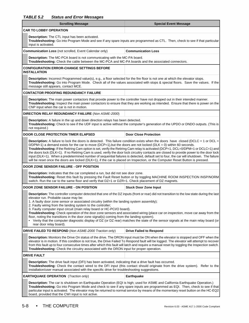
TABLE 5.2 Status and Error Messages
Scrolling Message Special Event Message
• THE COMPUTER Revision 6.03 - ASME A17.1-2000 Code Compliant5-8
CAR TO LOBBY OPERATION
Description: The CTL input has been activated.Troubleshooting: Go into Program Mode and see if any spare inputs are programmed as CTL. Then, check to see if that particularinput is activated.
Communication Loss (not scrolled, Event Calendar only) Communication Loss
Description: The MC-PCA board is not communicating with the MC-PA board.Troubleshooting: Check the cable between the MC-PCA and MC-PA boards and the associated connectors.
CONFIGURATION ERROR-CHANGE SETTINGS BEFOREINSTALLATION
Description: Incorrect Programmed value(s), e.g., a floor selected for the fire floor is not one at which the elevator stops.Troubleshooting: Go into Program Mode. Check all of the values associated with stops & special floors. Save the values. If themessage still appears, contact MCE.
CONTACTOR PROOFING REDUNDANCY FAILURE
Description: The main power contactors that provide power to the controller have not dropped out in their intended manner.Troubleshooting: Inspect the main power contactors to ensure that they are working as intended. Ensure that there is power on theCNP input when the car is not in motion.
DIRECTION RELAY REDUNDANCY FAILURE (Non ASME-2000)
Description: A failure in the up and down direction relays has been detected.Troubleshooting: Check to see if the UDF input is active without the computer’s generation of the UPDO or DNDO outputs. (This isnot required.)
DOOR CLOSE PROTECTION TIMER ELAPSED Door Close Protection
Description: A failure to lock the doors is detected. This failure condition exists when the doors have closed (DCLC = 1 or DCL =0/DPM=1) a demand exists for the car to move (DCP=1),but the doors are not locked (DLK = 0) within 60 seconds.Troubleshooting: If the Retiring Cam option is set, verify the Retiring Cam relay is activated (DCP=1, DCL=0/DPM=1 or DCLC=1) andthe doors lock (DLK=1). If no Retiring Cam is used, verify the door lock circuitry contacts are closed to provide power to the door lockinput (DLK=1). When a predetermined number of sequential failures is detected, default set to four, the car will shutdown. The failurewill be reset once the doors are locked (DLK=1), if the car is placed on Inspection, or the Computer Reset Button is pressed.
DOOR ZONE SENSOR FAILURE - OFF POSITION
Description: Indicates that the car completed a run, but did not see door zone.Troubleshooting: Reset this fault by pressing the Fault Reset button or by toggling MACHINE ROOM INSPECTION INSP/NORMswitch. Run the car to the same floor and verify that DZ=1 or DZR=1. Check placement of DZ magnets.
DOOR ZONE SENSOR FAILURE - ON POSITION Stuck Door Zone Input
Description: The controller computer detected that one of the DZ inputs (front or rear) did not transition to the low state during the lastelevator run. Probable cause may be:1. A faulty door zone sensor or associated circuitry (within the landing system assembly);2. Faulty wiring from the landing system to the controller;3. Faulty computer input circuit (main relay board or HC-PCI/O board).Troubleshooting: Check operation of the door zone sensors and associated wiring (place car on inspection, move car away from thefloor, noting the transitions in the door zone signal(s) coming from the landing system).• Verity that the computer diagnostic display of DZ (or DZ rear) matches the state of the sensor signals at the main relay board (or
rear door relay board).
DRIVE FAILED TO RESPOND (Non ASME-2000 Traction only) Drive Failed to Respond
Description: Monitors the Drive On status of the drive. The DRON input must be ON when the elevator is stopped and OFF when theelevator is in motion. If this condition is not true, the Drive Failed To Respond fault will be logged. The elevator will attempt to recoverfrom this fault up to four consecutive times after which this fault will latch and require a manual reset by toggling the Inspection switch.Troubleshooting: Check the circuitry associated with the DRON input for proper operation.
DRIVE FAULT
Description: The drive fault input (DFI) has been activated, indicating that a drive fault has occurred.Troubleshooting: Check the contact wired to the DFI input (this contact should originate from the drive system). Refer to theinstallation/user manual associated with the specific drive for troubleshooting suggestions.
EARTHQUAKE OPERATION (Traction only) Earthquake
Description: The car is shutdown on Earthquake Operation (EQI is high; used for ASME and California Earthquake Operation.)Troubleshooting: Go into Program Mode and check to see if any spare inputs are programmed as EQI. Then, check to see if thatparticular input is activated. The elevator may be returned to normal service by means of the momentary reset button on the HC-EQ2board, provided that the CWI input is not active.
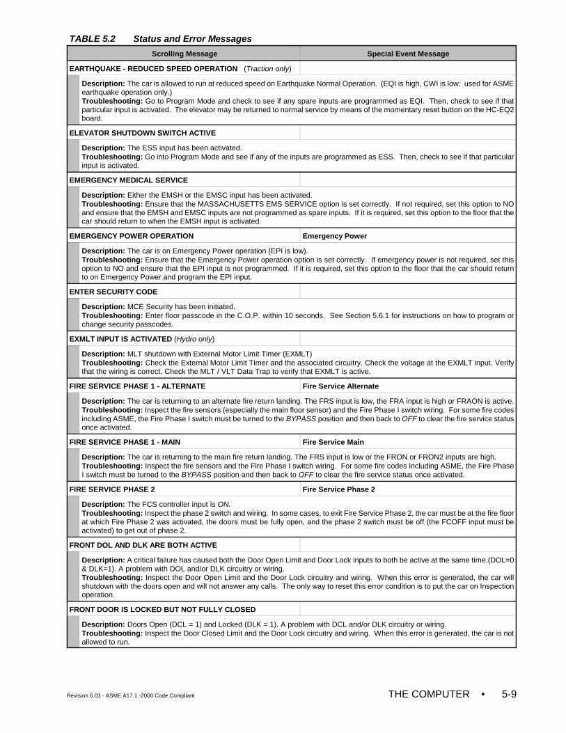
TABLE 5.2 Status and Error Messages
Scrolling Message Special Event Message
Revision 6.03 - ASME A17.1 -2000 Code Compliant THE COMPUTER • 5-9
EARTHQUAKE - REDUCED SPEED OPERATION (Traction only)
Description: The car is allowed to run at reduced speed on Earthquake Normal Operation. (EQI is high, CWI is low; used for ASMEearthquake operation only.)Troubleshooting: Go to Program Mode and check to see if any spare inputs are programmed as EQI. Then, check to see if thatparticular input is activated. The elevator may be returned to normal service by means of the momentary reset button on the HC-EQ2board.
ELEVATOR SHUTDOWN SWITCH ACTIVE
Description: The ESS input has been activated.Troubleshooting: Go into Program Mode and see if any of the inputs are programmed as ESS. Then, check to see if that particularinput is activated.
EMERGENCY MEDICAL SERVICE
Description: Either the EMSH or the EMSC input has been activated.Troubleshooting: Ensure that the MASSACHUSETTS EMS SERVICE option is set correctly. If not required, set this option to NOand ensure that the EMSH and EMSC inputs are not programmed as spare inputs. If it is required, set this option to the floor that thecar should return to when the EMSH input is activated.
EMERGENCY POWER OPERATION Emergency Power
Description: The car is on Emergency Power operation (EPI is low). Troubleshooting: Ensure that the Emergency Power operation option is set correctly. If emergency power is not required, set thisoption to NO and ensure that the EPI input is not programmed. If it is required, set this option to the floor that the car should returnto on Emergency Power and program the EPI input.
ENTER SECURITY CODE
Description: MCE Security has been initiated.Troubleshooting: Enter floor passcode in the C.O.P. within 10 seconds. See Section 5.6.1 for instructions on how to program orchange security passcodes.
EXMLT INPUT IS ACTIVATED (Hydro only)
Description: MLT shutdown with External Motor Limit Timer (EXMLT)Troubleshooting: Check the External Motor Limit Timer and the associated circuitry. Check the voltage at the EXMLT input. Verifythat the wiring is correct. Check the MLT / VLT Data Trap to verify that EXMLT is active.
FIRE SERVICE PHASE 1 - ALTERNATE Fire Service Alternate
Description: The car is returning to an alternate fire return landing. The FRS input is low, the FRA input is high or FRAON is active.Troubleshooting: Inspect the fire sensors (especially the main floor sensor) and the Fire Phase I switch wiring. For some fire codesincluding ASME, the Fire Phase I switch must be turned to the BYPASS position and then back to OFF to clear the fire service statusonce activated.
FIRE SERVICE PHASE 1 - MAIN Fire Service Main
Description: The car is returning to the main fire return landing. The FRS input is low or the FRON or FRON2 inputs are high.Troubleshooting: Inspect the fire sensors and the Fire Phase I switch wiring. For some fire codes including ASME, the Fire PhaseI switch must be turned to the BYPASS position and then back to OFF to clear the fire service status once activated.
FIRE SERVICE PHASE 2 Fire Service Phase 2
Description: The FCS controller input is ON. Troubleshooting: Inspect the phase 2 switch and wiring. In some cases, to exit Fire Service Phase 2, the car must be at the fire floorat which Fire Phase 2 was activated, the doors must be fully open, and the phase 2 switch must be off (the FCOFF input must beactivated) to get out of phase 2.
FRONT DOL AND DLK ARE BOTH ACTIVE
Description: A critical failure has caused both the Door Open Limit and Door Lock inputs to both be active at the same time.(DOL=0& DLK=1). A problem with DOL and/or DLK circuitry or wiring. Troubleshooting: Inspect the Door Open Limit and the Door Lock circuitry and wiring. When this error is generated, the car willshutdown with the doors open and will not answer any calls. The only way to reset this error condition is to put the car on Inspectionoperation.
FRONT DOOR IS LOCKED BUT NOT FULLY CLOSED
Description: Doors Open (DCL = 1) and Locked (DLK = 1). A problem with DCL and/or DLK circuitry or wiring.Troubleshooting: Inspect the Door Closed Limit and the Door Lock circuitry and wiring. When this error is generated, the car is notallowed to run.
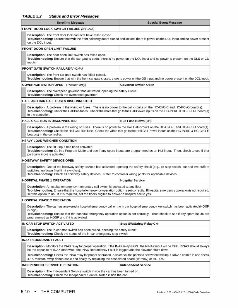
TABLE 5.2 Status and Error Messages
Scrolling Message Special Event Message
• THE COMPUTER Revision 6.03 - ASME A17.1-2000 Code Compliant5-10
FRONT DOOR LOCK SWITCH FAILURE (NYCHA)
Description: The front door lock contacts have failed closed. Troubleshooting: Ensure that with the front hoistway doors closed and locked, there is power on the DLS input and no power presenton the DCL input.
FRONT DOOR OPEN LIMIT FAILURE
Description: The door open limit switch has failed open.Troubleshooting: Ensure that the car gate is open, there is no power on the DOL input and no power is present on the DLS or CDinputs.
FRONT GATE SWITCH FAILURE(NYCHA)
Description: The front car gate switch has failed closed. Troubleshooting: Ensure that with the front car gate closed, there is power on the GS input and no power present on the DCL input.
GOVERNOR SWITCH OPEN (Traction only) Governor Switch Open
Description: The overspeed governor has activated, opening the safety circuit.Troubleshooting: Check the overspeed governor.
HALL AND CAR CALL BUSES DISCONNECTED
Description: A problem in the wiring or fuses. There is no power to the call circuits on the HC-CI/O-E and HC-PCI/O board(s).Troubleshooting: Check the Call Bus fuses. Check the wires that go to the Call Power inputs on the HC-PCI/O & HC-CI/O-E board(s)in the controller.
HALL CALL BUS IS DISCONNECTED Bus Fuse Blown (2H)
Description: A problem in the wiring or fuses. There is no power to the Hall Call circuits on the HC-CI/O-E and HC-PCI/O board(s).Troubleshooting: Check the Hall Call Bus fuse. Check the wires that go to the Hall Call Power inputs on the HC-PCI/O & HC-CI/O-Eboard(s) in the controller.
HEAVY LOAD WEIGHER CONDITION
Description: The HLI input has been activated.Troubleshooting: Go into Program Mode and see if any spare inputs are programmed as an HLI input. Then, check to see if thatparticular input is activated.
HOISTWAY SAFETY DEVICE OPEN
Description: One of the hoistway safety devices has activated, opening the safety circuit (e.g., pit stop switch, car and cwt buffersswitches, up/down final limit switches).Troubleshooting: Check all hoistway safety devices. Refer to controller wiring prints for applicable devices.
HOSPITAL PHASE 1 OPERATION Hospital Service
Description: A hospital emergency momentary call switch is activated at any floor.Troubleshooting: Ensure that the hospital emergency operation option is set correctly. If hospital emergency operation is not required,set this option to no. If it is required, set the floors eligible to answer a hospital call to yes.
HOSPITAL PHASE 2 OPERATION
Description: The car has answered a hospital emergency call or the in car hospital emergency key switch has been activated (HOSPis high).Troubleshooting: Ensure that the hospital emergency operation option is set correctly. Then check to see if any spare inputs areprogrammed as HOSP and if it is activated.
IN CAR STOP SWITCH ACTIVATED Stop SW/Safety Relay Ckt
Description: The in-car stop switch has been pulled, opening the safety circuit.Troubleshooting: Check the status of the in-car emergency stop switch.
INAX REDUNDANCY FAULT
Description: Monitors the INAX relay for proper operation. If the INAX relay is ON , the RINAX input will be OFF. RINAX should alwaysbe the opposite of INAX otherwise, the INAX Redundancy Fault is logged and the elevator shuts down.
Troubleshooting: Check the INAX relay for proper operation. Also check the prints to see where the input RINAX comes in and check47 K resistor, swap ribbon cable and finally try replacing the associated board (w/ relay) or HC-IOX.
INDEPENDENT SERVICE OPERATION Independent Service
Description: The Independent Service switch inside the car has been turned on.Troubleshooting: Check the Independent Service switch inside the car.
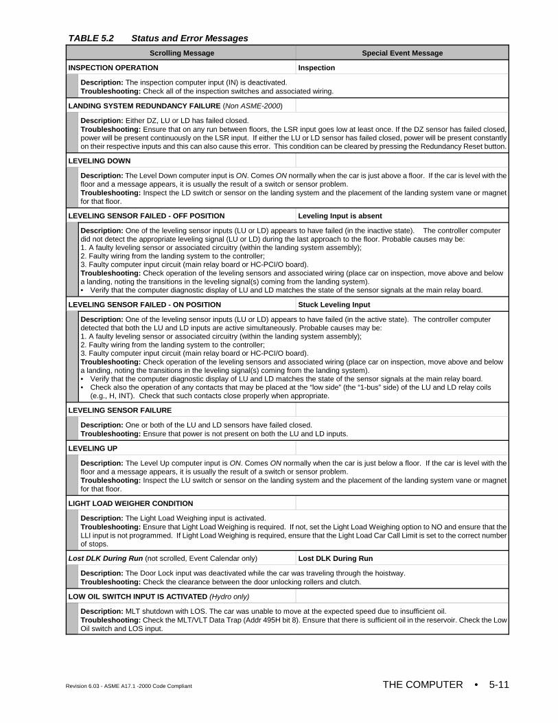
TABLE 5.2 Status and Error Messages
Scrolling Message Special Event Message
Revision 6.03 - ASME A17.1 -2000 Code Compliant THE COMPUTER • 5-11
INSPECTION OPERATION Inspection
Description: The inspection computer input (IN) is deactivated.Troubleshooting: Check all of the inspection switches and associated wiring.
LANDING SYSTEM REDUNDANCY FAILURE (Non ASME-2000)
Description: Either DZ, LU or LD has failed closed.Troubleshooting: Ensure that on any run between floors, the LSR input goes low at least once. If the DZ sensor has failed closed,power will be present continuously on the LSR input. If either the LU or LD sensor has failed closed, power will be present constantlyon their respective inputs and this can also cause this error. This condition can be cleared by pressing the Redundancy Reset button.
LEVELING DOWN
Description: The Level Down computer input is ON. Comes ON normally when the car is just above a floor. If the car is level with thefloor and a message appears, it is usually the result of a switch or sensor problem.Troubleshooting: Inspect the LD switch or sensor on the landing system and the placement of the landing system vane or magnetfor that floor.
LEVELING SENSOR FAILED - OFF POSITION Leveling Input is absent
Description: One of the leveling sensor inputs (LU or LD) appears to have failed (in the inactive state). The controller computerdid not detect the appropriate leveling signal (LU or LD) during the last approach to the floor. Probable causes may be: 1. A faulty leveling sensor or associated circuitry (within the landing system assembly);2. Faulty wiring from the landing system to the controller;3. Faulty computer input circuit (main relay board or HC-PCI/O board). Troubleshooting: Check operation of the leveling sensors and associated wiring (place car on inspection, move above and belowa landing, noting the transitions in the leveling signal(s) coming from the landing system). • Verify that the computer diagnostic display of LU and LD matches the state of the sensor signals at the main relay board.
LEVELING SENSOR FAILED - ON POSITION Stuck Leveling Input
Description: One of the leveling sensor inputs (LU or LD) appears to have failed (in the active state). The controller computerdetected that both the LU and LD inputs are active simultaneously. Probable causes may be: 1. A faulty leveling sensor or associated circuitry (within the landing system assembly);2. Faulty wiring from the landing system to the controller;3. Faulty computer input circuit (main relay board or HC-PCI/O board). Troubleshooting: Check operation of the leveling sensors and associated wiring (place car on inspection, move above and belowa landing, noting the transitions in the leveling signal(s) coming from the landing system). • Verify that the computer diagnostic display of LU and LD matches the state of the sensor signals at the main relay board. • Check also the operation of any contacts that may be placed at the “low side” (the “1-bus” side) of the LU and LD relay coils
(e.g., H, INT). Check that such contacts close properly when appropriate.
LEVELING SENSOR FAILURE
Description: One or both of the LU and LD sensors have failed closed.Troubleshooting: Ensure that power is not present on both the LU and LD inputs.
LEVELING UP
Description: The Level Up computer input is ON. Comes ON normally when the car is just below a floor. If the car is level with thefloor and a message appears, it is usually the result of a switch or sensor problem.Troubleshooting: Inspect the LU switch or sensor on the landing system and the placement of the landing system vane or magnetfor that floor.
LIGHT LOAD WEIGHER CONDITION
Description: The Light Load Weighing input is activated.Troubleshooting: Ensure that Light Load Weighing is required. If not, set the Light Load Weighing option to NO and ensure that theLLI input is not programmed. If Light Load Weighing is required, ensure that the Light Load Car Call Limit is set to the correct numberof stops.
Lost DLK During Run (not scrolled, Event Calendar only) Lost DLK During Run
Description: The Door Lock input was deactivated while the car was traveling through the hoistway. Troubleshooting: Check the clearance between the door unlocking rollers and clutch.
LOW OIL SWITCH INPUT IS ACTIVATED (Hydro only)
Description: MLT shutdown with LOS. The car was unable to move at the expected speed due to insufficient oil.Troubleshooting: Check the MLT/VLT Data Trap (Addr 495H bit 8). Ensure that there is sufficient oil in the reservoir. Check the LowOil switch and LOS input.

TABLE 5.2 Status and Error Messages
Scrolling Message Special Event Message
• THE COMPUTER Revision 6.03 - ASME A17.1-2000 Code Compliant5-12
LSA Movement Failure (not scrolled, Event Calendar only) LSA Movement Failure
Description: The car has failed to complete an LSA movement check after being idle for 10 minutes at a landing (see ABI, Alarm BellInput option).
MOTOR LIMIT TIMER (ANTI-STALL) ELAPSED Motor Limit Timer
Description: The Starter Overload or the Thermal Overload has tripped, or there is a mechanical problem that prevents or slows themotion of the car. Troubleshooting: To clear the condition, the car must be put on Inspection, then back into Normal operation, or the RESET buttonmust be pressed. Immediately check the starter and thermal overloads and all circuitry associated with the motor.
NORMAL OPERATION
Description: The elevator and controller are operating normally.
OVERLOAD CONDITION
Description: The car appears to be overloaded, as indicated by the load weigher input OVL.Troubleshooting: Check the OVL input. If power is present on the OVL input, the load weigher contact associated with this input isclosed. This contact being closed indicates to the elevator computer that the car is overloaded.
PASSCODE REQUEST
Description: The Passcode Request Option has been activated from the System Mode Menu.Troubleshooting: The system can be run on Inspection operation only. The passcode must be entered correctly in the System ModeMenu in order to deactivate this option and allow the controller to run normally (see Section 5.6.2).
Photo Eye Failure (not scrolled, Event Calendar only) Photo Eye Failure
Description: The Photo Eye input has been continuously active for a considerable period of time.Troubleshooting: Check for abnormal blockage of the optical device, frayed or defective photo eye relating cable or failure of the photoeye input circuit.
POWER TRANSFER INPUT ACTIVE
Description: The PTI input has been activated.Troubleshooting: Go into Program Mode and see if any of the inputs are programmed as PTI. Then, check to see if that particularinput is activated.
POWER UP SHUT DOWN DUE TO EARTHQUAKE (Traction only)
Description: The CWI and/or EQI input was detected high at power up. (Used for ASME Earthquake Operation only.)Troubleshooting: Go into Program Mode and check to see if any spare inputs are programmed as EQI or CWI. Then check to seeif those particular inputs are activated. The elevator may be returned to normal service by means of the momentary reset button onthe HC-EQ2 board. If both the EQI and CWI input were activated at power up, the MC-PCA board would need to be reset as well.
PRESSURE SWITCH ACTIVATED (Hydro only)
Description: This message is displayed when the Pressure Switch Input (PSS) is programmed and activated (low).Troubleshooting: Check the associated hardware device and take appropriate action.
REAR DOL & DLK ARE BOTH ACTIVE
Description: The Door Open Limit Rear and the Door Lock inputs are both active, DOLR=0 and DLK=1. A problem with DOLR and/orDLK circuitry or wiring.Troubleshooting: Inspect the Door Open Limit Rear and the Door Lock circuitry and wiring. When this error is generated, the car willshutdown with the doors open and will not answer any calls. The only way to reset this error condition is to put the car on Inspectionoperation.
REAR DOOR IS LOCKED BUT NOT FULLY CLOSED
Description: Rear Doors Open (DCLR = 1) and Locked (DLK = 1). Indicates a problem with DCLR and/or DLK circuitry or wiring.Troubleshooting: Inspect the Door Closed Limit Rear and the Door Lock circuitry and wiring. When this error is generated, the caris not allowed to run.
REAR DOOR LOCK SWITCH FAILURE (NYCHA)
Description: The rear door lock contacts have failed closed.Troubleshooting: Ensure that with the rear hoistway doors closed and locked, there is power on the DLSR input an no power presenton the DCLR input.
REAR DOOR OPEN LIMIT FAILURE
Description: The rear door open limit switch has failed open.Troubleshooting: Ensure that the rear car gate is open, there is no power on the DOLR input and no power is present on the DLSRor CDR inputs.
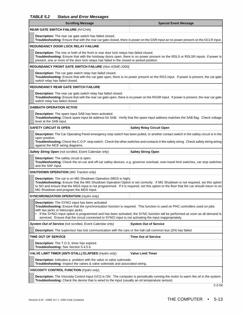
TABLE 5.2 Status and Error Messages
Scrolling Message Special Event Message
Revision 6.03 - ASME A17.1 -2000 Code Compliant THE COMPUTER • 5-13
REAR GATE SWITCH FAILURE (NYCHA)
Description: The rear car gate switch has failed closed.Troubleshooting: Ensure that with the rear car gate closed, there is power on the GSR input an no power present on the DCLR input.
REDUNDANCY DOOR LOCK RELAY FAILURE
Description: The one or both of the front or rear door lock relays has failed closed.Troubleshooting: Ensure that with the hoistway doors open, there is no power present on the RDLS or RDLSR inputs. If power ispresent, one or more of the door lock relays has failed in the closed or picked position.
REDUNDANCY FRONT GATE SWITCH FAILURE (Non ASME-2000)
Description: The car gate switch relay has failed closed.Troubleshooting: Ensure that with the car gate open, there is no power present on the RGS input. If power is present, the car gateswitch relay has failed closed.
REDUNDANCY REAR GATE SWITCH FAILURE
Description: The rear car gate switch relay has failed closed.Troubleshooting: Ensure that with the rear car gate open, there is no power on the RGSR input. If power is present, the rear car gateswitch relay has failed closed.
SABBATH OPERATION ACTIVE
Description: The spare input SAB has been activated.Troubleshooting: Check spare input bit address for SAB. Verify that the spare input address matches the SAB flag. Check voltagelevel at the SAB input.
SAFETY CIRCUIT IS OPEN Safety Relay Circuit Open
Description: The Car Operating Panel emergency stop switch has been pulled, or another contact switch in the safety circuit is in theopen position.Troubleshooting: Check the C.O.P. stop switch. Check the other switches and contacts in the safety string. Check safety string wiringagainst the MCE wiring diagrams.
Safety String Open (not scrolled, Event Calendar only) Safety String Open
Description: The safety circuit is open.Troubleshooting: Check the on-car and off-car safety devices, e.g. governor overload, over-travel limit switches, car stop switchesand the SAF input.
SHUTDOWN OPERATION (MG Traction only)
Description: The car is on MG Shutdown Operation (MGS is high).Troubleshooting: Ensure that the MG Shutdown Operation Option is set correctly. If MG Shutdown is not required, set this optionto NO and ensure that the MGS Input is not programmed. If it is required, set this option to the floor that the car should return to onMG Shutdown and program the MGS Input.
SYNCHRONIZATION OPERATION (Hydro only)
Description: The SYNCI input has been activatedTroubleshooting: Ensure that the synchronization function is required. This function is used on PHC controllers used on jobs with two jacks or telescopic jacks. • If the SYNCI Input option is programmed and has been activated, the SYNC function will be performed as soon as all demand is
serviced. Ensure that the circuit connected to SYNCI input is not activating the input inappropriately.
System Out of Service (not scrolled, Event Calendar only) System Out of Service
Description: The supervisor has lost communication with the cars or the hall call common bus (2H) has failed.
TIME OUT OF SERVICE Time Out of Service
Description: The T.O.S. timer has expired.Troubleshooting: See Section 5.4.5.6.
VALVE LIMIT TIMER (ANTI-STALL) ELAPSED (Hydro only) Valve Limit Timer
Description: Indicates a problem with the valve or valve solenoids.Troubleshooting: Inspect the valves & valve solenoids and associated wiring.
VISCOSITY CONTROL FUNCTION (Hydro only)
Description: The Viscosity Control Input (VCI) is ON. The computer is periodically running the motor to warm the oil in the system.Troubleshooting: Check the device that is wired to the input (usually an oil temperature sensor).
2-2-04
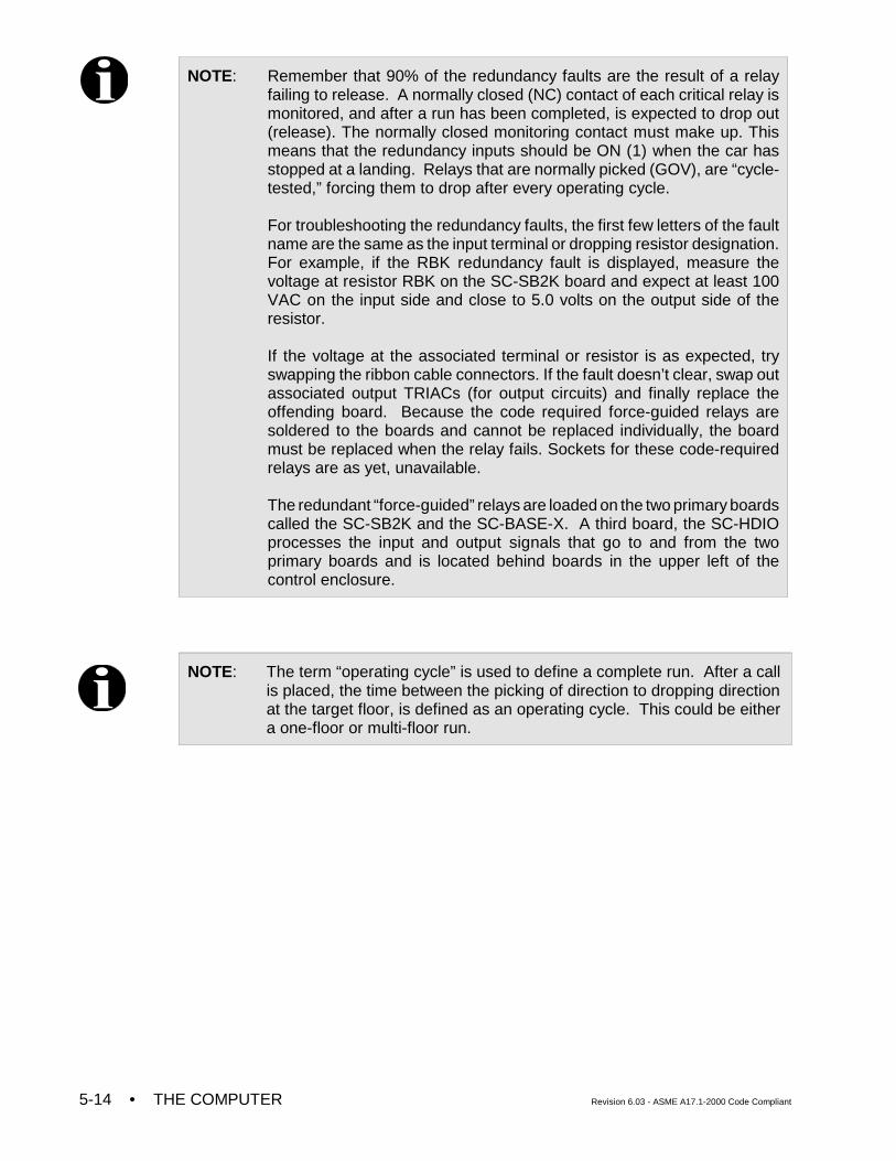
• THE COMPUTER Revision 6.03 - ASME A17.1-2000 Code Compliant5-14
NOTE: Remember that 90% of the redundancy faults are the result of a relayfailing to release. A normally closed (NC) contact of each critical relay ismonitored, and after a run has been completed, is expected to drop out(release). The normally closed monitoring contact must make up. Thismeans that the redundancy inputs should be ON (1) when the car hasstopped at a landing. Relays that are normally picked (GOV), are “cycle-tested,” forcing them to drop after every operating cycle.
For troubleshooting the redundancy faults, the first few letters of the faultname are the same as the input terminal or dropping resistor designation.For example, if the RBK redundancy fault is displayed, measure thevoltage at resistor RBK on the SC-SB2K board and expect at least 100VAC on the input side and close to 5.0 volts on the output side of theresistor.
If the voltage at the associated terminal or resistor is as expected, tryswapping the ribbon cable connectors. If the fault doesn’t clear, swap outassociated output TRIACs (for output circuits) and finally replace theoffending board. Because the code required force-guided relays aresoldered to the boards and cannot be replaced individually, the boardmust be replaced when the relay fails. Sockets for these code-requiredrelays are as yet, unavailable.
The redundant “force-guided” relays are loaded on the two primary boardscalled the SC-SB2K and the SC-BASE-X. A third board, the SC-HDIOprocesses the input and output signals that go to and from the twoprimary boards and is located behind boards in the upper left of thecontrol enclosure.
NOTE: The term “operating cycle” is used to define a complete run. After a callis placed, the time between the picking of direction to dropping directionat the target floor, is defined as an operating cycle. This could be eithera one-floor or multi-floor run.
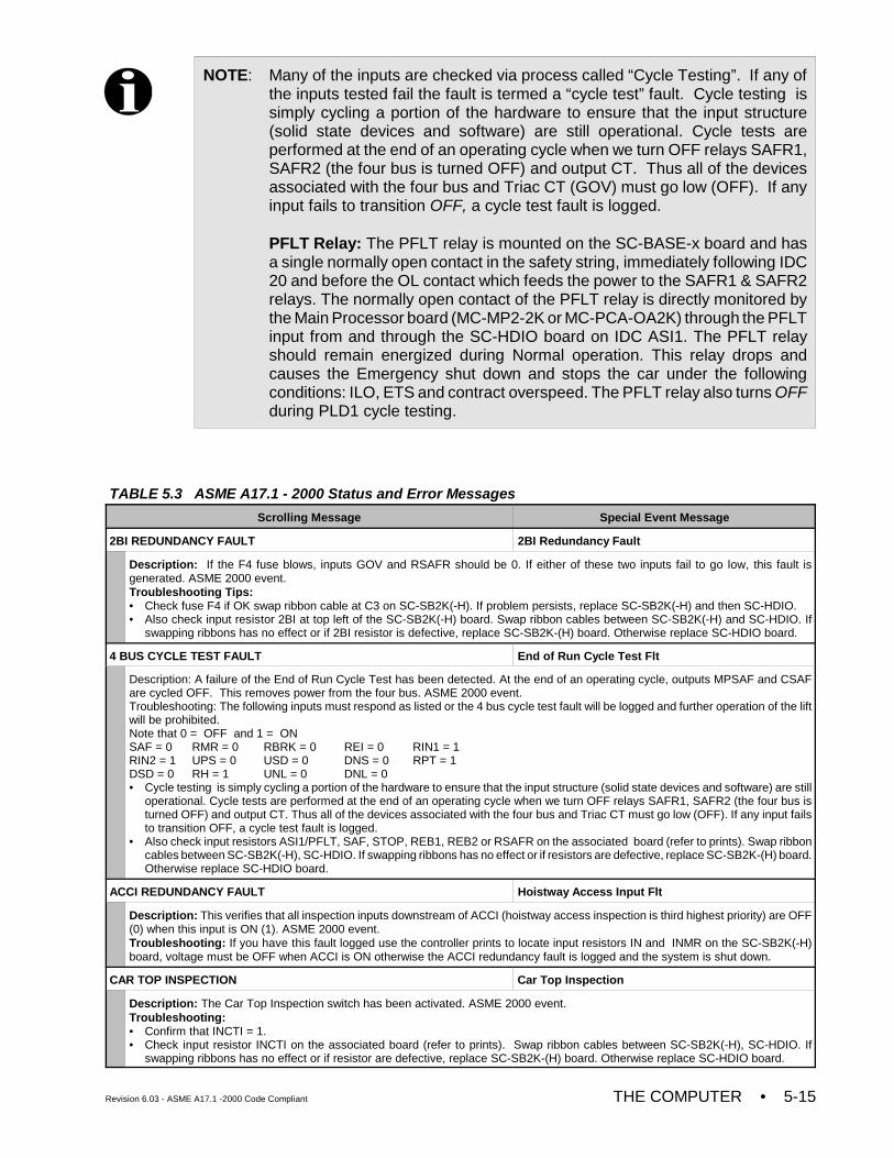
Revision 6.03 - ASME A17.1 -2000 Code Compliant THE COMPUTER • 5-15
TABLE 5.3 ASME A17.1 - 2000 Status and Error Messages
Scrolling Message Special Event Message
2BI REDUNDANCY FAULT 2BI Redundancy Fault
Description: If the F4 fuse blows, inputs GOV and RSAFR should be 0. If either of these two inputs fail to go low, this fault isgenerated. ASME 2000 event.Troubleshooting Tips:• Check fuse F4 if OK swap ribbon cable at C3 on SC-SB2K(-H). If problem persists, replace SC-SB2K(-H) and then SC-HDIO.• Also check input resistor 2BI at top left of the SC-SB2K(-H) board. Swap ribbon cables between SC-SB2K(-H) and SC-HDIO. If
swapping ribbons has no effect or if 2BI resistor is defective, replace SC-SB2K-(H) board. Otherwise replace SC-HDIO board.
4 BUS CYCLE TEST FAULT End of Run Cycle Test Flt
Description: A failure of the End of Run Cycle Test has been detected. At the end of an operating cycle, outputs MPSAF and CSAFare cycled OFF. This removes power from the four bus. ASME 2000 event. Troubleshooting: The following inputs must respond as listed or the 4 bus cycle test fault will be logged and further operation of the liftwill be prohibited.Note that 0 = OFF and 1 = ONSAF = 0 RMR = 0 RBRK = 0 REI = 0 RIN1 = 1 RIN2 = 1 UPS = 0 USD = 0 DNS = 0 RPT = 1DSD = 0 RH = 1 UNL = 0 DNL = 0• Cycle testing is simply cycling a portion of the hardware to ensure that the input structure (solid state devices and software) are still
operational. Cycle tests are performed at the end of an operating cycle when we turn OFF relays SAFR1, SAFR2 (the four bus isturned OFF) and output CT. Thus all of the devices associated with the four bus and Triac CT must go low (OFF). If any input failsto transition OFF, a cycle test fault is logged.
• Also check input resistors ASI1/PFLT, SAF, STOP, REB1, REB2 or RSAFR on the associated board (refer to prints). Swap ribboncables between SC-SB2K(-H), SC-HDIO. If swapping ribbons has no effect or if resistors are defective, replace SC-SB2K-(H) board.Otherwise replace SC-HDIO board.
ACCI REDUNDANCY FAULT Hoistway Access Input Flt
Description: This verifies that all inspection inputs downstream of ACCI (hoistway access inspection is third highest priority) are OFF(0) when this input is ON (1). ASME 2000 event. Troubleshooting: If you have this fault logged use the controller prints to locate input resistors IN and INMR on the SC-SB2K(-H)board, voltage must be OFF when ACCI is ON otherwise the ACCI redundancy fault is logged and the system is shut down.
CAR TOP INSPECTION Car Top Inspection
Description: The Car Top Inspection switch has been activated. ASME 2000 event.Troubleshooting: • Confirm that INCTI = 1.• Check input resistor INCTI on the associated board (refer to prints). Swap ribbon cables between SC-SB2K(-H), SC-HDIO. If
swapping ribbons has no effect or if resistor are defective, replace SC-SB2K-(H) board. Otherwise replace SC-HDIO board.
NOTE: Many of the inputs are checked via process called “Cycle Testing”. If any ofthe inputs tested fail the fault is termed a “cycle test” fault. Cycle testing issimply cycling a portion of the hardware to ensure that the input structure(solid state devices and software) are still operational. Cycle tests areperformed at the end of an operating cycle when we turn OFF relays SAFR1,SAFR2 (the four bus is turned OFF) and output CT. Thus all of the devicesassociated with the four bus and Triac CT (GOV) must go low (OFF). If anyinput fails to transition OFF, a cycle test fault is logged.
PFLT Relay: The PFLT relay is mounted on the SC-BASE-x board and hasa single normally open contact in the safety string, immediately following IDC20 and before the OL contact which feeds the power to the SAFR1 & SAFR2relays. The normally open contact of the PFLT relay is directly monitored bythe Main Processor board (MC-MP2-2K or MC-PCA-OA2K) through the PFLTinput from and through the SC-HDIO board on IDC ASI1. The PFLT relayshould remain energized during Normal operation. This relay drops andcauses the Emergency shut down and stops the car under the followingconditions: ILO, ETS and contract overspeed. The PFLT relay also turns OFFduring PLD1 cycle testing.
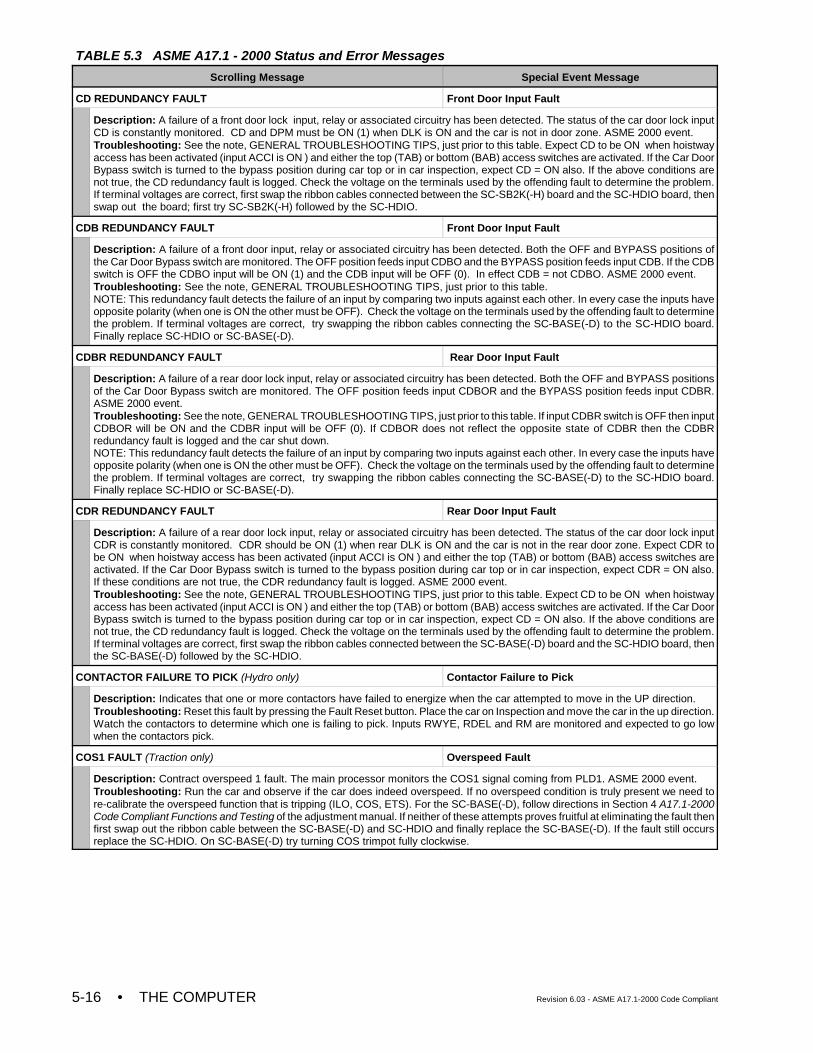
TABLE 5.3 ASME A17.1 - 2000 Status and Error Messages
Scrolling Message Special Event Message
• THE COMPUTER Revision 6.03 - ASME A17.1-2000 Code Compliant5-16
CD REDUNDANCY FAULT Front Door Input Fault
Description: A failure of a front door lock input, relay or associated circuitry has been detected. The status of the car door lock inputCD is constantly monitored. CD and DPM must be ON (1) when DLK is ON and the car is not in door zone. ASME 2000 event.Troubleshooting: See the note, GENERAL TROUBLESHOOTING TIPS, just prior to this table. Expect CD to be ON when hoistwayaccess has been activated (input ACCI is ON ) and either the top (TAB) or bottom (BAB) access switches are activated. If the Car DoorBypass switch is turned to the bypass position during car top or in car inspection, expect CD = ON also. If the above conditions arenot true, the CD redundancy fault is logged. Check the voltage on the terminals used by the offending fault to determine the problem.If terminal voltages are correct, first swap the ribbon cables connected between the SC-SB2K(-H) board and the SC-HDIO board, thenswap out the board; first try SC-SB2K(-H) followed by the SC-HDIO.
CDB REDUNDANCY FAULT Front Door Input Fault
Description: A failure of a front door input, relay or associated circuitry has been detected. Both the OFF and BYPASS positions ofthe Car Door Bypass switch are monitored. The OFF position feeds input CDBO and the BYPASS position feeds input CDB. If the CDBswitch is OFF the CDBO input will be ON (1) and the CDB input will be OFF (0). In effect CDB = not CDBO. ASME 2000 event.Troubleshooting: See the note, GENERAL TROUBLESHOOTING TIPS, just prior to this table.NOTE: This redundancy fault detects the failure of an input by comparing two inputs against each other. In every case the inputs haveopposite polarity (when one is ON the other must be OFF). Check the voltage on the terminals used by the offending fault to determinethe problem. If terminal voltages are correct, try swapping the ribbon cables connecting the SC-BASE(-D) to the SC-HDIO board.Finally replace SC-HDIO or SC-BASE(-D).
CDBR REDUNDANCY FAULT Rear Door Input Fault
Description: A failure of a rear door lock input, relay or associated circuitry has been detected. Both the OFF and BYPASS positionsof the Car Door Bypass switch are monitored. The OFF position feeds input CDBOR and the BYPASS position feeds input CDBR.ASME 2000 event. Troubleshooting: See the note, GENERAL TROUBLESHOOTING TIPS, just prior to this table. If input CDBR switch is OFF then inputCDBOR will be ON and the CDBR input will be OFF (0). If CDBOR does not reflect the opposite state of CDBR then the CDBRredundancy fault is logged and the car shut down. NOTE: This redundancy fault detects the failure of an input by comparing two inputs against each other. In every case the inputs haveopposite polarity (when one is ON the other must be OFF). Check the voltage on the terminals used by the offending fault to determinethe problem. If terminal voltages are correct, try swapping the ribbon cables connecting the SC-BASE(-D) to the SC-HDIO board.Finally replace SC-HDIO or SC-BASE(-D).
CDR REDUNDANCY FAULT Rear Door Input Fault
Description: A failure of a rear door lock input, relay or associated circuitry has been detected. The status of the car door lock inputCDR is constantly monitored. CDR should be ON (1) when rear DLK is ON and the car is not in the rear door zone. Expect CDR tobe ON when hoistway access has been activated (input ACCI is ON ) and either the top (TAB) or bottom (BAB) access switches areactivated. If the Car Door Bypass switch is turned to the bypass position during car top or in car inspection, expect CDR = ON also.If these conditions are not true, the CDR redundancy fault is logged. ASME 2000 event.Troubleshooting: See the note, GENERAL TROUBLESHOOTING TIPS, just prior to this table. Expect CD to be ON when hoistwayaccess has been activated (input ACCI is ON ) and either the top (TAB) or bottom (BAB) access switches are activated. If the Car DoorBypass switch is turned to the bypass position during car top or in car inspection, expect CD = ON also. If the above conditions arenot true, the CD redundancy fault is logged. Check the voltage on the terminals used by the offending fault to determine the problem.If terminal voltages are correct, first swap the ribbon cables connected between the SC-BASE(-D) board and the SC-HDIO board, thenthe SC-BASE(-D) followed by the SC-HDIO.
CONTACTOR FAILURE TO PICK (Hydro only) Contactor Failure to Pick
Description: Indicates that one or more contactors have failed to energize when the car attempted to move in the UP direction.Troubleshooting: Reset this fault by pressing the Fault Reset button. Place the car on Inspection and move the car in the up direction.Watch the contactors to determine which one is failing to pick. Inputs RWYE, RDEL and RM are monitored and expected to go lowwhen the contactors pick.
COS1 FAULT (Traction only) Overspeed Fault
Description: Contract overspeed 1 fault. The main processor monitors the COS1 signal coming from PLD1. ASME 2000 event. Troubleshooting: Run the car and observe if the car does indeed overspeed. If no overspeed condition is truly present we need tore-calibrate the overspeed function that is tripping (ILO, COS, ETS). For the SC-BASE(-D), follow directions in Section 4 A17.1-2000Code Compliant Functions and Testing of the adjustment manual. If neither of these attempts proves fruitful at eliminating the fault thenfirst swap out the ribbon cable between the SC-BASE(-D) and SC-HDIO and finally replace the SC-BASE(-D). If the fault still occursreplace the SC-HDIO. On SC-BASE(-D) try turning COS trimpot fully clockwise.
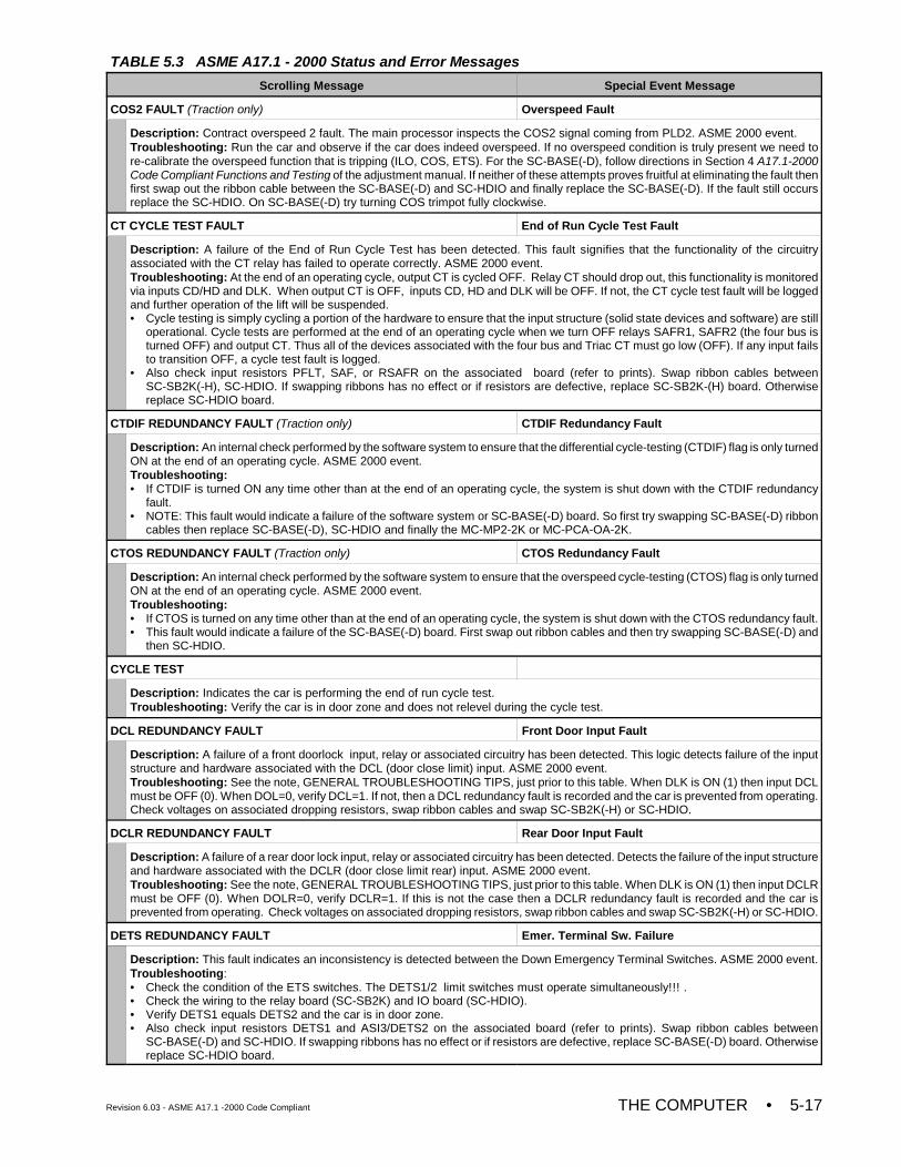
TABLE 5.3 ASME A17.1 - 2000 Status and Error Messages
Scrolling Message Special Event Message
Revision 6.03 - ASME A17.1 -2000 Code Compliant THE COMPUTER • 5-17
COS2 FAULT (Traction only) Overspeed Fault
Description: Contract overspeed 2 fault. The main processor inspects the COS2 signal coming from PLD2. ASME 2000 event.Troubleshooting: Run the car and observe if the car does indeed overspeed. If no overspeed condition is truly present we need tore-calibrate the overspeed function that is tripping (ILO, COS, ETS). For the SC-BASE(-D), follow directions in Section 4 A17.1-2000Code Compliant Functions and Testing of the adjustment manual. If neither of these attempts proves fruitful at eliminating the fault thenfirst swap out the ribbon cable between the SC-BASE(-D) and SC-HDIO and finally replace the SC-BASE(-D). If the fault still occursreplace the SC-HDIO. On SC-BASE(-D) try turning COS trimpot fully clockwise.
CT CYCLE TEST FAULT End of Run Cycle Test Fault
Description: A failure of the End of Run Cycle Test has been detected. This fault signifies that the functionality of the circuitryassociated with the CT relay has failed to operate correctly. ASME 2000 event. Troubleshooting: At the end of an operating cycle, output CT is cycled OFF. Relay CT should drop out, this functionality is monitoredvia inputs CD/HD and DLK. When output CT is OFF, inputs CD, HD and DLK will be OFF. If not, the CT cycle test fault will be loggedand further operation of the lift will be suspended.• Cycle testing is simply cycling a portion of the hardware to ensure that the input structure (solid state devices and software) are still
operational. Cycle tests are performed at the end of an operating cycle when we turn OFF relays SAFR1, SAFR2 (the four bus isturned OFF) and output CT. Thus all of the devices associated with the four bus and Triac CT must go low (OFF). If any input failsto transition OFF, a cycle test fault is logged.
• Also check input resistors PFLT, SAF, or RSAFR on the associated board (refer to prints). Swap ribbon cables betweenSC-SB2K(-H), SC-HDIO. If swapping ribbons has no effect or if resistors are defective, replace SC-SB2K-(H) board. Otherwisereplace SC-HDIO board.
CTDIF REDUNDANCY FAULT (Traction only) CTDIF Redundancy Fault
Description: An internal check performed by the software system to ensure that the differential cycle-testing (CTDIF) flag is only turnedON at the end of an operating cycle. ASME 2000 event.Troubleshooting: • If CTDIF is turned ON any time other than at the end of an operating cycle, the system is shut down with the CTDIF redundancy
fault.• NOTE: This fault would indicate a failure of the software system or SC-BASE(-D) board. So first try swapping SC-BASE(-D) ribbon
cables then replace SC-BASE(-D), SC-HDIO and finally the MC-MP2-2K or MC-PCA-OA-2K.
CTOS REDUNDANCY FAULT (Traction only) CTOS Redundancy Fault
Description: An internal check performed by the software system to ensure that the overspeed cycle-testing (CTOS) flag is only turnedON at the end of an operating cycle. ASME 2000 event.Troubleshooting: • If CTOS is turned on any time other than at the end of an operating cycle, the system is shut down with the CTOS redundancy fault.• This fault would indicate a failure of the SC-BASE(-D) board. First swap out ribbon cables and then try swapping SC-BASE(-D) and
then SC-HDIO.
CYCLE TEST
Description: Indicates the car is performing the end of run cycle test.Troubleshooting: Verify the car is in door zone and does not relevel during the cycle test.
DCL REDUNDANCY FAULT Front Door Input Fault
Description: A failure of a front doorlock input, relay or associated circuitry has been detected. This logic detects failure of the inputstructure and hardware associated with the DCL (door close limit) input. ASME 2000 event.Troubleshooting: See the note, GENERAL TROUBLESHOOTING TIPS, just prior to this table. When DLK is ON (1) then input DCLmust be OFF (0). When DOL=0, verify DCL=1. If not, then a DCL redundancy fault is recorded and the car is prevented from operating.Check voltages on associated dropping resistors, swap ribbon cables and swap SC-SB2K(-H) or SC-HDIO.
DCLR REDUNDANCY FAULT Rear Door Input Fault
Description: A failure of a rear door lock input, relay or associated circuitry has been detected. Detects the failure of the input structureand hardware associated with the DCLR (door close limit rear) input. ASME 2000 event. Troubleshooting: See the note, GENERAL TROUBLESHOOTING TIPS, just prior to this table. When DLK is ON (1) then input DCLRmust be OFF (0). When DOLR=0, verify DCLR=1. If this is not the case then a DCLR redundancy fault is recorded and the car isprevented from operating. Check voltages on associated dropping resistors, swap ribbon cables and swap SC-SB2K(-H) or SC-HDIO.
DETS REDUNDANCY FAULT Emer. Terminal Sw. Failure
Description: This fault indicates an inconsistency is detected between the Down Emergency Terminal Switches. ASME 2000 event.Troubleshooting: • Check the condition of the ETS switches. The DETS1/2 limit switches must operate simultaneously!!! .• Check the wiring to the relay board (SC-SB2K) and IO board (SC-HDIO).• Verify DETS1 equals DETS2 and the car is in door zone.• Also check input resistors DETS1 and ASI3/DETS2 on the associated board (refer to prints). Swap ribbon cables between
SC-BASE(-D) and SC-HDIO. If swapping ribbons has no effect or if resistors are defective, replace SC-BASE(-D) board. Otherwisereplace SC-HDIO board.
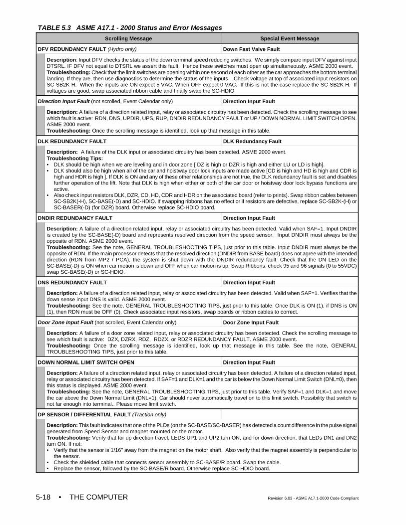
TABLE 5.3 ASME A17.1 - 2000 Status and Error Messages
Scrolling Message Special Event Message
• THE COMPUTER Revision 6.03 - ASME A17.1-2000 Code Compliant5-18
DFV REDUNDANCY FAULT (Hydro only) Down Fast Valve Fault
Description: Input DFV checks the status of the down terminal speed reducing switches. We simply compare input DFV against inputDTSRL. IF DFV not equal to DTSRL we assert this fault. Hence these switches must open up simultaneously. ASME 2000 event.Troubleshooting: Check that the limit switches are opening within one second of each other as the car approaches the bottom terminallanding. If they are, then use diagnostics to determine the status of the inputs. Check voltage at top of associated input resistors onSC-SB2K-H. When the inputs are ON expect 5 VAC. When OFF expect 0 VAC. If this is not the case replace the SC-SB2K-H. Ifvoltages are good, swap associated ribbon cable and finally swap the SC-HDIO
Direction Input Fault (not scrolled, Event Calendar only) Direction Input Fault
Description: A failure of a direction related input, relay or associated circuitry has been detected. Check the scrolling message to seewhich fault is active: RDN, DNS, UPDIR, UPS, RUP, DNDIR REDUNDANCY FAULT or UP / DOWN NORMAL LIMIT SWITCH OPEN.ASME 2000 event.Troubleshooting: Once the scrolling message is identified, look up that message in this table.
DLK REDUNDANCY FAULT DLK Redundancy Fault
Description: A failure of the DLK input or associated circuitry has been detected. ASME 2000 event.Troubleshooting Tips:• DLK should be high when we are leveling and in door zone [ DZ is high or DZR is high and either LU or LD is high].• DLK should also be high when all of the car and hoistway door lock inputs are made active [CD is high and HD is high and CDR is
high and HDR is high ]. If DLK is ON and any of these other relationships are not true, the DLK redundancy fault is set and disablesfurther operation of the lift. Note that DLK is high when either or both of the car door or hoistway door lock bypass functions areactive.
• Also check input resistors DLK, DZR, CD, HD, CDR and HDR on the associated board (refer to prints). Swap ribbon cables betweenSC-SB2K(-H), SC-BASE(-D) and SC-HDIO. If swapping ribbons has no effect or if resistors are defective, replace SC-SB2K-(H) orSC-BASER(-D) (for DZR) board. Otherwise replace SC-HDIO board.
DNDIR REDUNDANCY FAULT Direction Input Fault
Description: A failure of a direction related input, relay or associated circuitry has been detected. Valid when SAF=1. Input DNDIRis created by the SC-BASE(-D) board and represents resolved direction from the speed sensor. Input DNDIR must always be theopposite of RDN. ASME 2000 event.Troubleshooting: See the note, GENERAL TROUBLESHOOTING TIPS, just prior to this table. Input DNDIR must always be theopposite of RDN. If the main processor detects that the resolved direction (DNDIR from BASE board) does not agree with the intendeddirection (RDN from MP2 / PCA), the system is shut down with the DNDIR redundancy fault. Check that the DN LED on theSC-BASE(-D) is ON when car motion is down and OFF when car motion is up. Swap Ribbons, check 95 and 96 signals (0 to 55VDC)swap SC-BASE(-D) or SC-HDIO.
DNS REDUNDANCY FAULT Direction Input Fault
Description: A failure of a direction related input, relay or associated circuitry has been detected. Valid when SAF=1. Verifies that thedown sense input DNS is valid. ASME 2000 event. Troubleshooting: See the note, GENERAL TROUBLESHOOTING TIPS, just prior to this table. Once DLK is ON (1), if DNS is ON(1), then RDN must be OFF (0). Check associated input resistors, swap boards or ribbon cables to correct.
Door Zone Input Fault (not scrolled, Event Calendar only) Door Zone Input Fault
Description: A failure of a door zone related input, relay or associated circuitry has been detected. Check the scrolling message tosee which fault is active: DZX, DZRX, RDZ, RDZX, or RDZR REDUNDANCY FAULT. ASME 2000 event.Troubleshooting: Once the scrolling message is identified, look up that message in this table. See the note, GENERALTROUBLESHOOTING TIPS, just prior to this table.
DOWN NORMAL LIMIT SWITCH OPEN Direction Input Fault
Description: A failure of a direction related input, relay or associated circuitry has been detected. A failure of a direction related input,relay or associated circuitry has been detected. If SAF=1 and DLK=1 and the car is below the Down Normal Limit Switch (DNL=0), thenthis status is displayed. ASME 2000 event.Troubleshooting: See the note, GENERAL TROUBLESHOOTING TIPS, just prior to this table. Verify SAF=1 and DLK=1 and movethe car above the Down Normal Limit (DNL=1). Car should never automatically travel on to this limit switch. Possibility that switch isnot far enough into terminal.. Please move limit switch.
DP SENSOR / DIFFERENTIAL FAULT (Traction only)
Description: This fault indicates that one of the PLDs (on the SC-BASE/SC-BASER) has detected a count difference in the pulse signalgenerated from Speed Sensor and magnet mounted on the motor.Troubleshooting: Verify that for up direction travel, LEDS UP1 and UP2 turn ON, and for down direction, that LEDs DN1 and DN2turn ON. If not:• Verify that the sensor is 1/16" away from the magnet on the motor shaft. Also verify that the magnet assembly is perpendicular to
the sensor. • Check the shielded cable that connects sensor assembly to SC-BASE/R board. Swap the cable.• Replace the sensor, followed by the SC-BASE/R board. Otherwise replace SC-HDIO board.
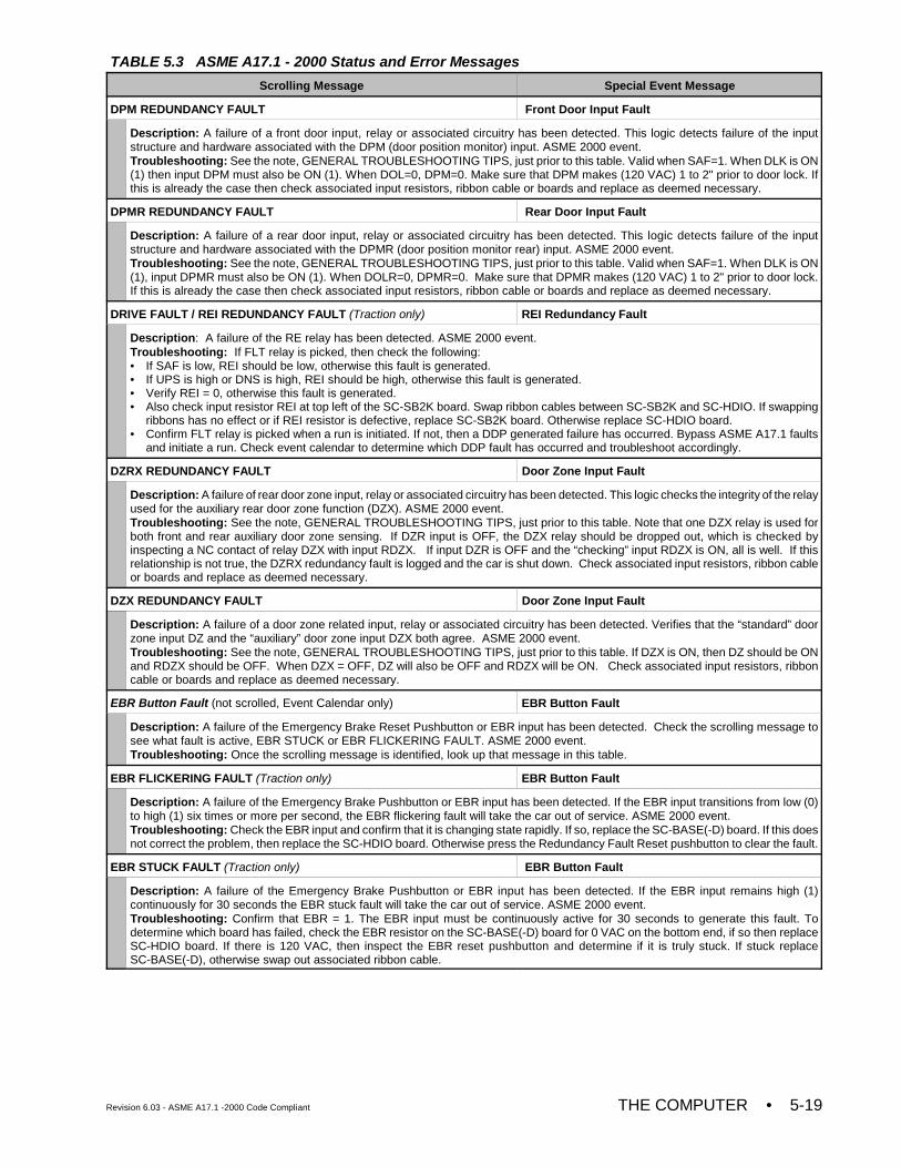
TABLE 5.3 ASME A17.1 - 2000 Status and Error Messages
Scrolling Message Special Event Message
Revision 6.03 - ASME A17.1 -2000 Code Compliant THE COMPUTER • 5-19
DPM REDUNDANCY FAULT Front Door Input Fault
Description: A failure of a front door input, relay or associated circuitry has been detected. This logic detects failure of the inputstructure and hardware associated with the DPM (door position monitor) input. ASME 2000 event.Troubleshooting: See the note, GENERAL TROUBLESHOOTING TIPS, just prior to this table. Valid when SAF=1. When DLK is ON(1) then input DPM must also be ON (1). When DOL=0, DPM=0. Make sure that DPM makes (120 VAC) 1 to 2" prior to door lock. Ifthis is already the case then check associated input resistors, ribbon cable or boards and replace as deemed necessary.
DPMR REDUNDANCY FAULT Rear Door Input Fault
Description: A failure of a rear door input, relay or associated circuitry has been detected. This logic detects failure of the inputstructure and hardware associated with the DPMR (door position monitor rear) input. ASME 2000 event.Troubleshooting: See the note, GENERAL TROUBLESHOOTING TIPS, just prior to this table. Valid when SAF=1. When DLK is ON(1), input DPMR must also be ON (1). When DOLR=0, DPMR=0. Make sure that DPMR makes (120 VAC) 1 to 2" prior to door lock.If this is already the case then check associated input resistors, ribbon cable or boards and replace as deemed necessary.
DRIVE FAULT / REI REDUNDANCY FAULT (Traction only) REI Redundancy Fault
Description: A failure of the RE relay has been detected. ASME 2000 event.Troubleshooting: If FLT relay is picked, then check the following:• If SAF is low, REI should be low, otherwise this fault is generated.• If UPS is high or DNS is high, REI should be high, otherwise this fault is generated.• Verify REI = 0, otherwise this fault is generated.• Also check input resistor REI at top left of the SC-SB2K board. Swap ribbon cables between SC-SB2K and SC-HDIO. If swapping
ribbons has no effect or if REI resistor is defective, replace SC-SB2K board. Otherwise replace SC-HDIO board.• Confirm FLT relay is picked when a run is initiated. If not, then a DDP generated failure has occurred. Bypass ASME A17.1 faults
and initiate a run. Check event calendar to determine which DDP fault has occurred and troubleshoot accordingly.
DZRX REDUNDANCY FAULT Door Zone Input Fault
Description: A failure of rear door zone input, relay or associated circuitry has been detected. This logic checks the integrity of the relayused for the auxiliary rear door zone function (DZX). ASME 2000 event.Troubleshooting: See the note, GENERAL TROUBLESHOOTING TIPS, just prior to this table. Note that one DZX relay is used forboth front and rear auxiliary door zone sensing. If DZR input is OFF, the DZX relay should be dropped out, which is checked byinspecting a NC contact of relay DZX with input RDZX. If input DZR is OFF and the “checking” input RDZX is ON, all is well. If thisrelationship is not true, the DZRX redundancy fault is logged and the car is shut down. Check associated input resistors, ribbon cableor boards and replace as deemed necessary.
DZX REDUNDANCY FAULT Door Zone Input Fault
Description: A failure of a door zone related input, relay or associated circuitry has been detected. Verifies that the “standard” doorzone input DZ and the “auxiliary” door zone input DZX both agree. ASME 2000 event.Troubleshooting: See the note, GENERAL TROUBLESHOOTING TIPS, just prior to this table. If DZX is ON, then DZ should be ONand RDZX should be OFF. When DZX = OFF, DZ will also be OFF and RDZX will be ON. Check associated input resistors, ribboncable or boards and replace as deemed necessary.
EBR Button Fault (not scrolled, Event Calendar only) EBR Button Fault
Description: A failure of the Emergency Brake Reset Pushbutton or EBR input has been detected. Check the scrolling message tosee what fault is active, EBR STUCK or EBR FLICKERING FAULT. ASME 2000 event.Troubleshooting: Once the scrolling message is identified, look up that message in this table.
EBR FLICKERING FAULT (Traction only) EBR Button Fault
Description: A failure of the Emergency Brake Pushbutton or EBR input has been detected. If the EBR input transitions from low (0)to high (1) six times or more per second, the EBR flickering fault will take the car out of service. ASME 2000 event. Troubleshooting: Check the EBR input and confirm that it is changing state rapidly. If so, replace the SC-BASE(-D) board. If this doesnot correct the problem, then replace the SC-HDIO board. Otherwise press the Redundancy Fault Reset pushbutton to clear the fault.
EBR STUCK FAULT (Traction only) EBR Button Fault
Description: A failure of the Emergency Brake Pushbutton or EBR input has been detected. If the EBR input remains high (1)continuously for 30 seconds the EBR stuck fault will take the car out of service. ASME 2000 event.Troubleshooting: Confirm that EBR = 1. The EBR input must be continuously active for 30 seconds to generate this fault. Todetermine which board has failed, check the EBR resistor on the SC-BASE(-D) board for 0 VAC on the bottom end, if so then replaceSC-HDIO board. If there is 120 VAC, then inspect the EBR reset pushbutton and determine if it is truly stuck. If stuck replaceSC-BASE(-D), otherwise swap out associated ribbon cable.
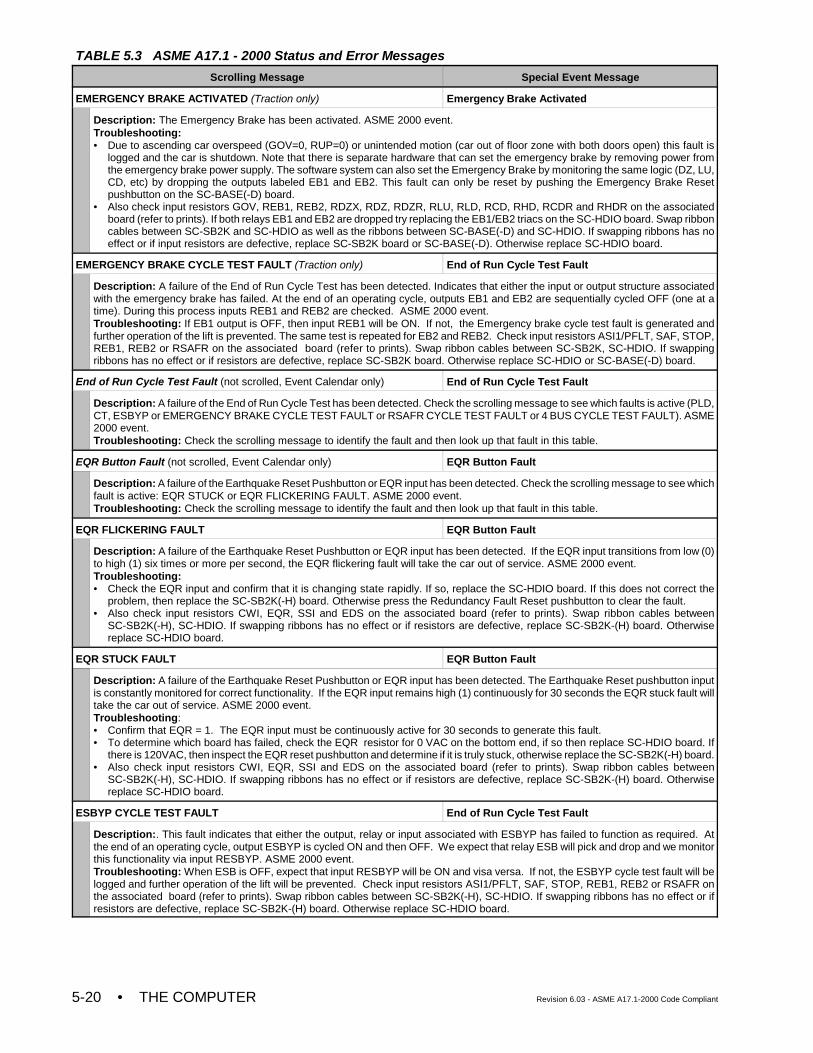
TABLE 5.3 ASME A17.1 - 2000 Status and Error Messages
Scrolling Message Special Event Message
• THE COMPUTER Revision 6.03 - ASME A17.1-2000 Code Compliant5-20
EMERGENCY BRAKE ACTIVATED (Traction only) Emergency Brake Activated
Description: The Emergency Brake has been activated. ASME 2000 event.Troubleshooting:• Due to ascending car overspeed (GOV=0, RUP=0) or unintended motion (car out of floor zone with both doors open) this fault is
logged and the car is shutdown. Note that there is separate hardware that can set the emergency brake by removing power fromthe emergency brake power supply. The software system can also set the Emergency Brake by monitoring the same logic (DZ, LU,CD, etc) by dropping the outputs labeled EB1 and EB2. This fault can only be reset by pushing the Emergency Brake Resetpushbutton on the SC-BASE(-D) board.
• Also check input resistors GOV, REB1, REB2, RDZX, RDZ, RDZR, RLU, RLD, RCD, RHD, RCDR and RHDR on the associatedboard (refer to prints). If both relays EB1 and EB2 are dropped try replacing the EB1/EB2 triacs on the SC-HDIO board. Swap ribboncables between SC-SB2K and SC-HDIO as well as the ribbons between SC-BASE(-D) and SC-HDIO. If swapping ribbons has noeffect or if input resistors are defective, replace SC-SB2K board or SC-BASE(-D). Otherwise replace SC-HDIO board.
EMERGENCY BRAKE CYCLE TEST FAULT (Traction only) End of Run Cycle Test Fault
Description: A failure of the End of Run Cycle Test has been detected. Indicates that either the input or output structure associatedwith the emergency brake has failed. At the end of an operating cycle, outputs EB1 and EB2 are sequentially cycled OFF (one at atime). During this process inputs REB1 and REB2 are checked. ASME 2000 event.Troubleshooting: If EB1 output is OFF, then input REB1 will be ON. If not, the Emergency brake cycle test fault is generated andfurther operation of the lift is prevented. The same test is repeated for EB2 and REB2. Check input resistors ASI1/PFLT, SAF, STOP,REB1, REB2 or RSAFR on the associated board (refer to prints). Swap ribbon cables between SC-SB2K, SC-HDIO. If swappingribbons has no effect or if resistors are defective, replace SC-SB2K board. Otherwise replace SC-HDIO or SC-BASE(-D) board.
End of Run Cycle Test Fault (not scrolled, Event Calendar only) End of Run Cycle Test Fault
Description: A failure of the End of Run Cycle Test has been detected. Check the scrolling message to see which faults is active (PLD,CT, ESBYP or EMERGENCY BRAKE CYCLE TEST FAULT or RSAFR CYCLE TEST FAULT or 4 BUS CYCLE TEST FAULT). ASME2000 event.Troubleshooting: Check the scrolling message to identify the fault and then look up that fault in this table.
EQR Button Fault (not scrolled, Event Calendar only) EQR Button Fault
Description: A failure of the Earthquake Reset Pushbutton or EQR input has been detected. Check the scrolling message to see whichfault is active: EQR STUCK or EQR FLICKERING FAULT. ASME 2000 event.Troubleshooting: Check the scrolling message to identify the fault and then look up that fault in this table.
EQR FLICKERING FAULT EQR Button Fault
Description: A failure of the Earthquake Reset Pushbutton or EQR input has been detected. If the EQR input transitions from low (0)to high (1) six times or more per second, the EQR flickering fault will take the car out of service. ASME 2000 event.Troubleshooting:• Check the EQR input and confirm that it is changing state rapidly. If so, replace the SC-HDIO board. If this does not correct the
problem, then replace the SC-SB2K(-H) board. Otherwise press the Redundancy Fault Reset pushbutton to clear the fault.• Also check input resistors CWI, EQR, SSI and EDS on the associated board (refer to prints). Swap ribbon cables between
SC-SB2K(-H), SC-HDIO. If swapping ribbons has no effect or if resistors are defective, replace SC-SB2K-(H) board. Otherwisereplace SC-HDIO board.
EQR STUCK FAULT EQR Button Fault
Description: A failure of the Earthquake Reset Pushbutton or EQR input has been detected. The Earthquake Reset pushbutton inputis constantly monitored for correct functionality. If the EQR input remains high (1) continuously for 30 seconds the EQR stuck fault willtake the car out of service. ASME 2000 event.Troubleshooting:• Confirm that EQR = 1. The EQR input must be continuously active for 30 seconds to generate this fault.• To determine which board has failed, check the EQR resistor for 0 VAC on the bottom end, if so then replace SC-HDIO board. If
there is 120VAC, then inspect the EQR reset pushbutton and determine if it is truly stuck, otherwise replace the SC-SB2K(-H) board.• Also check input resistors CWI, EQR, SSI and EDS on the associated board (refer to prints). Swap ribbon cables between
SC-SB2K(-H), SC-HDIO. If swapping ribbons has no effect or if resistors are defective, replace SC-SB2K-(H) board. Otherwisereplace SC-HDIO board.
ESBYP CYCLE TEST FAULT End of Run Cycle Test Fault
Description:. This fault indicates that either the output, relay or input associated with ESBYP has failed to function as required. Atthe end of an operating cycle, output ESBYP is cycled ON and then OFF. We expect that relay ESB will pick and drop and we monitorthis functionality via input RESBYP. ASME 2000 event.Troubleshooting: When ESB is OFF, expect that input RESBYP will be ON and visa versa. If not, the ESBYP cycle test fault will belogged and further operation of the lift will be prevented. Check input resistors ASI1/PFLT, SAF, STOP, REB1, REB2 or RSAFR onthe associated board (refer to prints). Swap ribbon cables between SC-SB2K(-H), SC-HDIO. If swapping ribbons has no effect or ifresistors are defective, replace SC-SB2K-(H) board. Otherwise replace SC-HDIO board.
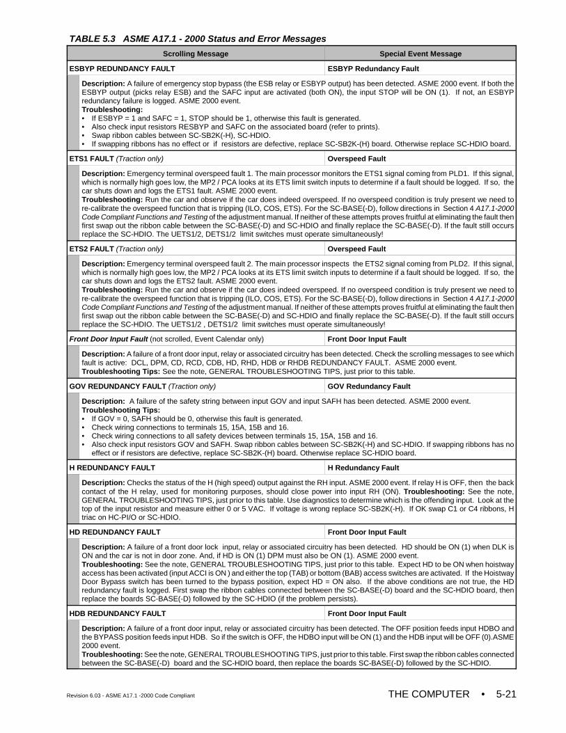
TABLE 5.3 ASME A17.1 - 2000 Status and Error Messages
Scrolling Message Special Event Message
Revision 6.03 - ASME A17.1 -2000 Code Compliant THE COMPUTER • 5-21
ESBYP REDUNDANCY FAULT ESBYP Redundancy Fault
Description: A failure of emergency stop bypass (the ESB relay or ESBYP output) has been detected. ASME 2000 event. If both theESBYP output (picks relay ESB) and the SAFC input are activated (both ON), the input STOP will be ON (1). If not, an ESBYPredundancy failure is logged. ASME 2000 event.Troubleshooting: • If ESBYP = 1 and SAFC = 1, STOP should be 1, otherwise this fault is generated.• Also check input resistors RESBYP and SAFC on the associated board (refer to prints). • Swap ribbon cables between SC-SB2K(-H), SC-HDIO.• If swapping ribbons has no effect or if resistors are defective, replace SC-SB2K-(H) board. Otherwise replace SC-HDIO board.
ETS1 FAULT (Traction only) Overspeed Fault
Description: Emergency terminal overspeed fault 1. The main processor monitors the ETS1 signal coming from PLD1. If this signal,which is normally high goes low, the MP2 / PCA looks at its ETS limit switch inputs to determine if a fault should be logged. If so, thecar shuts down and logs the ETS1 fault. ASME 2000 event.Troubleshooting: Run the car and observe if the car does indeed overspeed. If no overspeed condition is truly present we need tore-calibrate the overspeed function that is tripping (ILO, COS, ETS). For the SC-BASE(-D), follow directions in Section 4 A17.1-2000Code Compliant Functions and Testing of the adjustment manual. If neither of these attempts proves fruitful at eliminating the fault thenfirst swap out the ribbon cable between the SC-BASE(-D) and SC-HDIO and finally replace the SC-BASE(-D). If the fault still occursreplace the SC-HDIO. The UETS1/2, DETS1/2 limit switches must operate simultaneously!
ETS2 FAULT (Traction only) Overspeed Fault
Description: Emergency terminal overspeed fault 2. The main processor inspects the ETS2 signal coming from PLD2. If this signal,which is normally high goes low, the MP2 / PCA looks at its ETS limit switch inputs to determine if a fault should be logged. If so, thecar shuts down and logs the ETS2 fault. ASME 2000 event.Troubleshooting: Run the car and observe if the car does indeed overspeed. If no overspeed condition is truly present we need tore-calibrate the overspeed function that is tripping (ILO, COS, ETS). For the SC-BASE(-D), follow directions in Section 4 A17.1-2000Code Compliant Functions and Testing of the adjustment manual. If neither of these attempts proves fruitful at eliminating the fault thenfirst swap out the ribbon cable between the SC-BASE(-D) and SC-HDIO and finally replace the SC-BASE(-D). If the fault still occursreplace the SC-HDIO. The UETS1/2 , DETS1/2 limit switches must operate simultaneously!
Front Door Input Fault (not scrolled, Event Calendar only) Front Door Input Fault
Description: A failure of a front door input, relay or associated circuitry has been detected. Check the scrolling messages to see whichfault is active: DCL, DPM, CD, RCD, CDB, HD, RHD, HDB or RHDB REDUNDANCY FAULT. ASME 2000 event.Troubleshooting Tips: See the note, GENERAL TROUBLESHOOTING TIPS, just prior to this table.
GOV REDUNDANCY FAULT (Traction only) GOV Redundancy Fault
Description: A failure of the safety string between input GOV and input SAFH has been detected. ASME 2000 event.Troubleshooting Tips:• If GOV = 0, SAFH should be 0, otherwise this fault is generated.• Check wiring connections to terminals 15, 15A, 15B and 16.• Check wiring connections to all safety devices between terminals 15, 15A, 15B and 16. • Also check input resistors GOV and SAFH. Swap ribbon cables between SC-SB2K(-H) and SC-HDIO. If swapping ribbons has no
effect or if resistors are defective, replace SC-SB2K-(H) board. Otherwise replace SC-HDIO board.
H REDUNDANCY FAULT H Redundancy Fault
Description: Checks the status of the H (high speed) output against the RH input. ASME 2000 event. If relay H is OFF, then the backcontact of the H relay, used for monitoring purposes, should close power into input RH (ON). Troubleshooting: See the note,GENERAL TROUBLESHOOTING TIPS, just prior to this table. Use diagnostics to determine which is the offending input. Look at thetop of the input resistor and measure either 0 or 5 VAC. If voltage is wrong replace SC-SB2K(-H). If OK swap C1 or C4 ribbons, Htriac on HC-PI/O or SC-HDIO.
HD REDUNDANCY FAULT Front Door Input Fault
Description: A failure of a front door lock input, relay or associated circuitry has been detected. HD should be ON (1) when DLK isON and the car is not in door zone. And, if HD is ON (1) DPM must also be ON (1). ASME 2000 event.Troubleshooting: See the note, GENERAL TROUBLESHOOTING TIPS, just prior to this table. Expect HD to be ON when hoistwayaccess has been activated (input ACCI is ON ) and either the top (TAB) or bottom (BAB) access switches are activated. If the HoistwayDoor Bypass switch has been turned to the bypass position, expect HD = ON also. If the above conditions are not true, the HDredundancy fault is logged. First swap the ribbon cables connected between the SC-BASE(-D) board and the SC-HDIO board, thenreplace the boards SC-BASE(-D) followed by the SC-HDIO (if the problem persists).
HDB REDUNDANCY FAULT Front Door Input Fault
Description: A failure of a front door input, relay or associated circuitry has been detected. The OFF position feeds input HDBO andthe BYPASS position feeds input HDB. So if the switch is OFF, the HDBO input will be ON (1) and the HDB input will be OFF (0).ASME2000 event.Troubleshooting: See the note, GENERAL TROUBLESHOOTING TIPS, just prior to this table. First swap the ribbon cables connectedbetween the SC-BASE(-D) board and the SC-HDIO board, then replace the boards SC-BASE(-D) followed by the SC-HDIO.
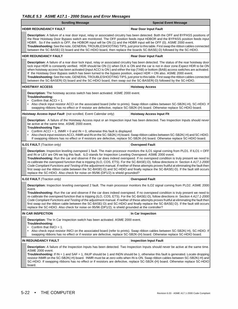
TABLE 5.3 ASME A17.1 - 2000 Status and Error Messages
Scrolling Message Special Event Message
• THE COMPUTER Revision 6.03 - ASME A17.1-2000 Code Compliant5-22
HDBR REDUNDANCY FAULT Rear Door Input Fault
Description: A failure of a rear door input, relay or associated circuitry has been detected. Both the OFF and BYPASS positions ofthe Rear Hoistway Door Bypass switch are monitored. The OFF position feeds input HDBOR and the BYPASS position feeds inputHDBR. So if the switch is OFF, the HDBOR input will be ON (1) and the HDBR input will be OFF (0). ASME 2000 event.Troubleshooting: See the note, GENERAL TROUBLESHOOTING TIPS, just prior to this table. First swap the ribbon cables connectedbetween the SC-BASE(-D) board and the SC-HDIO board, then replace the boards SC-BASE(-D) followed by the SC-HDIO.
HDR REDUNDANCY FAULT Rear Door Input Fault
Description: A failure of a rear door lock input, relay or associated circuitry has been detected. The status of the rear hoistway doorlock input HDR is constantly verified. HDR should be ON (1) when DLK is ON and the car is not in door zone.Expect HDR to be ONwhen hoistway access has been activated (input ACCI is ON ) and either the top (TAB) or bottom (BAB) access switches are activated.If the Hoistway Door Bypass switch has been turned to the bypass position, expect HDR = ON also. ASME 2000 event. Troubleshooting: See the note, GENERAL TROUBLESHOOTING TIPS, just prior to this table. First swap the ribbon cables connectedbetween the SC-BASER(-D) board and the SC-HDIO board, then swap out the SC-BASER(-D) followed by the SC-HDIO.
HOISTWAY ACCESS Hoistway Access
Description: The hoistway access switch has been activated. ASME 2000 event.Troubleshooting: • Confirm that ACCI = 1.• Also check input resistor ACCI on the associated board (refer to prints). Swap ribbon cables between SC-SB2K(-H), SC-HDIO. If
swapping ribbons has no effect or if resistor are defective, replace SC-SB2K-(H) board. Otherwise replace SC-HDIO board.
Hoistway Access Input Fault (not scrolled, Event Calendar only) Hoistway Access Input Flt
Description: A failure of the Hoistway Access input or an Inspection input has been detected. Two Inspection Inputs should neverbe active at the same time. ASME 2000 event.Troubleshooting Tips:• Confirm ACCI = 1, INMR = 0 and IN = 0, otherwise this fault is displayed.• Also check input resistors ACCI, INMR and IN on the SC-SB2K(-H) board. Swap ribbon cables between SC-SB2K(-H) and SC-HDIO.
If swapping ribbons has no effect or if resistors are defective, replace SC-SB2K-(H) board. Otherwise replace SC-HDIO board.
ILO1 FAULT (Traction only) Overspeed Fault
Description: Inspection leveling overspeed 1 fault. The main processor monitors the ILO1 signal coming from PLD1. If ILO1 = OFFand IN or LEV are ON we log this fault. ILO stands for Inspection Leveling Overspeed. ASME 2000 event.Troubleshooting: Run the car and observe if the car does indeed overspeed. If no overspeed condition is truly present we need tore-calibrate the overspeed function that is tripping (ILO, COS, ETS). For the SC-BASE(-D), follow directions in Section 4 A17.1-2000Code Compliant Functions and Testing of the adjustment manual. If neither of these attempts proves fruitful at eliminating the fault thenfirst swap out the ribbon cable between the SC-BASE(-D) and SC-HDIO and finally replace the SC-BASE(-D). If the fault still occursreplace the SC-HDIO. Also check for noise on 95/96 (DP1/2) is shield grounded?
ILO2 FAULT (Traction only) Overspeed Fault
Description: Inspection leveling overspeed 2 fault. The main processor monitors the ILO2 signal coming from PLD2. ASME 2000event.Troubleshooting: Run the car and observe if the car does indeed overspeed. If no overspeed condition is truly present we need tore-calibrate the overspeed function that is tripping (ILO, COS, ETS). For the SC-BASE(-D), follow directions in Section 4 A17.1-2000Code Compliant Functions and Testing of the adjustment manual. If neither of these attempts proves fruitful at eliminating the fault thenfirst swap out the ribbon cable between the SC-BASE(-D) and SC-HDIO and finally replace the SC-BASE(-D). If the fault still occursreplace the SC-HDIO. Also check for noise on 95/96 (DP1/2); is shield grounded at the controller?
IN CAR INSPECTION In Car Inspection
Description: The In Car Inspection switch has been activated. ASME 2000 event.Troubleshooting:• Confirm that INICI = 1.• Also check input resistor INICI on the associated board (refer to prints). Swap ribbon cables between SC-SB2K(-H), SC-HDIO. If
swapping ribbons has no effect or if resistor are defective, replace SC-SB2K-(H) board. Otherwise replace SC-HDIO board.
IN REDUNDANCY FAULT Inspection Input Fault
Description: A failure of the Inspection Inputs has been detected. Two Inspection Inputs should never be active at the same time.ASME 2000 event.Troubleshooting: If IN = 1 and SAF = 1, INUP should be 1 and INDN should be 1, otherwise this fault is generated. Locate droppingresistor INMR on the SC-SB2K(-H) board. INMR must be at zero volts when IN is ON. Swap ribbon cables between SC-SB2K(-H) andSC-HDIO. If swapping ribbons has no effect or if resistors are defective, replace SC-SB2K-(H) board. Otherwise replace SC-HDIOboard.
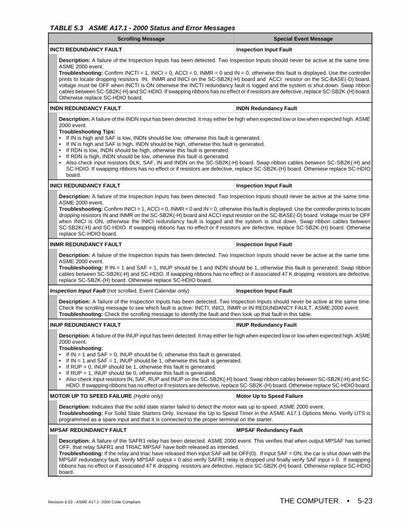
TABLE 5.3 ASME A17.1 - 2000 Status and Error Messages
Scrolling Message Special Event Message
Revision 6.03 - ASME A17.1 -2000 Code Compliant THE COMPUTER • 5-23
INCTI REDUNDANCY FAULT Inspection Input Fault
Description: A failure of the Inspection Inputs has been detected. Two Inspection Inputs should never be active at the same time.ASME 2000 event.Troubleshooting: Confirm INCTI = 1, INICI = 0, ACCI = 0, INMR = 0 and IN = 0, otherwise this fault is displayed. Use the controllerprints to locate dropping resistors IN, INMR and INICI on the SC-SB2K(-H) board and ACCI resistor on the SC-BASE(-D) board,voltage must be OFF when INCTI is ON otherwise the INCTI redundancy fault is logged and the system is shut down. Swap ribboncables between SC-SB2K(-H) and SC-HDIO. If swapping ribbons has no effect or if resistors are defective, replace SC-SB2K-(H) board.Otherwise replace SC-HDIO board.
INDN REDUNDANCY FAULT INDN Redundancy Fault
Description: A failure of the INDN input has been detected. It may either be high when expected low or low when expected high. ASME2000 event.Troubleshooting Tips:• If IN is high and SAF is low, INDN should be low, otherwise this fault is generated.• If IN is high and SAF is high, INDN should be high, otherwise this fault is generated.• If RDN is low, INDN should be high, otherwise this fault is generated.• If RDN is high, INDN should be low, otherwise this fault is generated.• Also check input resistors DLK, SAF, IN and INDN on the SC-SB2K(-H) board. Swap ribbon cables between SC-SB2K(-H) and
SC-HDIO. If swapping ribbons has no effect or if resistors are defective, replace SC-SB2K-(H) board. Otherwise replace SC-HDIOboard.
INICI REDUNDANCY FAULT Inspection Input Fault
Description: A failure of the Inspection Inputs has been detected. Two Inspection Inputs should never be active at the same time.ASME 2000 event.Troubleshooting: Confirm INICI = 1, ACCI = 0, INMR = 0 and IN = 0, otherwise this fault is displayed. Use the controller prints to locatedropping resistors IN and INMR on the SC-SB2K(-H) board and ACCI input resistor on the SC-BASE(-D) board. Voltage must be OFFwhen INICI is ON, otherwise the INICI redundancy fault is logged and the system is shut down. Swap ribbon cables betweenSC-SB2K(-H) and SC-HDIO. If swapping ribbons has no effect or if resistors are defective, replace SC-SB2K-(H) board. Otherwisereplace SC-HDIO board.
INMR REDUNDANCY FAULT Inspection Input Fault
Description: A failure of the Inspection Inputs has been detected. Two Inspection Inputs should never be active at the same time.ASME 2000 event.Troubleshooting: If IN = 1 and SAF = 1, INUP should be 1 and INDN should be 1, otherwise this fault is generated. Swap ribboncables between SC-SB2K(-H) and SC-HDIO. If swapping ribbons has no effect or if associated 47 K dropping resistors are defective,replace SC-SB2K-(H) board. Otherwise replace SC-HDIO board.
Inspection Input Fault (not scrolled, Event Calendar only) Inspection Input Fault
Description: A failure of the Inspection Inputs has been detected. Two Inspection Inputs should never be active at the same time.Check the scrolling message to see which fault is active: INCTI, INICI, INMR or IN REDUNDANCY FAULT. ASME 2000 event.Troubleshooting: Check the scrolling message to identify the fault and then look up that fault in this table.
INUP REDUNDANCY FAULT INUP Redundancy Fault
Description: A failure of the INUP input has been detected. It may either be high when expected low or low when expected high. ASME2000 event.Troubleshooting:• If IN = 1 and SAF = 0, INUP should be 0, otherwise this fault is generated.• If IN = 1 and SAF = 1, INUP should be 1, otherwise this fault is generated.• If RUP = 0, INUP should be 1, otherwise this fault is generated.• If RUP = 1, INUP should be 0, otherwise this fault is generated.• Also check input resistors IN, SAF, RUP and INUP on the SC-SB2K(-H) board. Swap ribbon cables between SC-SB2K(-H) and SC-
HDIO. If swapping ribbons has no effect or if resistors are defective, replace SC-SB2K-(H) board. Otherwise replace SC-HDIO board.
MOTOR UP TO SPEED FAILURE (Hydro only) Motor Up to Speed Failure
Description: Indicates that the solid state starter failed to detect the motor was up to speed. ASME 2000 event.Troubleshooting: For Solid State Starters Only. Increase the Up to Speed Timer in the ASME A17.1 Options Menu. Verify UTS isprogrammed as a spare input and that it is connected to the proper terminal on the starter.
MPSAF REDUNDANCY FAULT MPSAF Redundancy Fault
Description: A failure of the SAFR1 relay has been detected. ASME 2000 event. This verifies that when output MPSAF has turnedOFF, that relay SAFR1 and TRIAC MPSAF have both released as intended.Troubleshooting: If the relay and triac have released then input SAF will be OFF(0). If input SAF = ON, the car is shut down with theMPSAF redundancy fault. Verify MPSAF output = 0 also verify SAFR1 relay is dropped und finally verify SAF input = 0. If swappingribbons has no effect or if associated 47 K dropping resistors are defective, replace SC-SB2K-(H) board. Otherwise replace SC-HDIOboard.
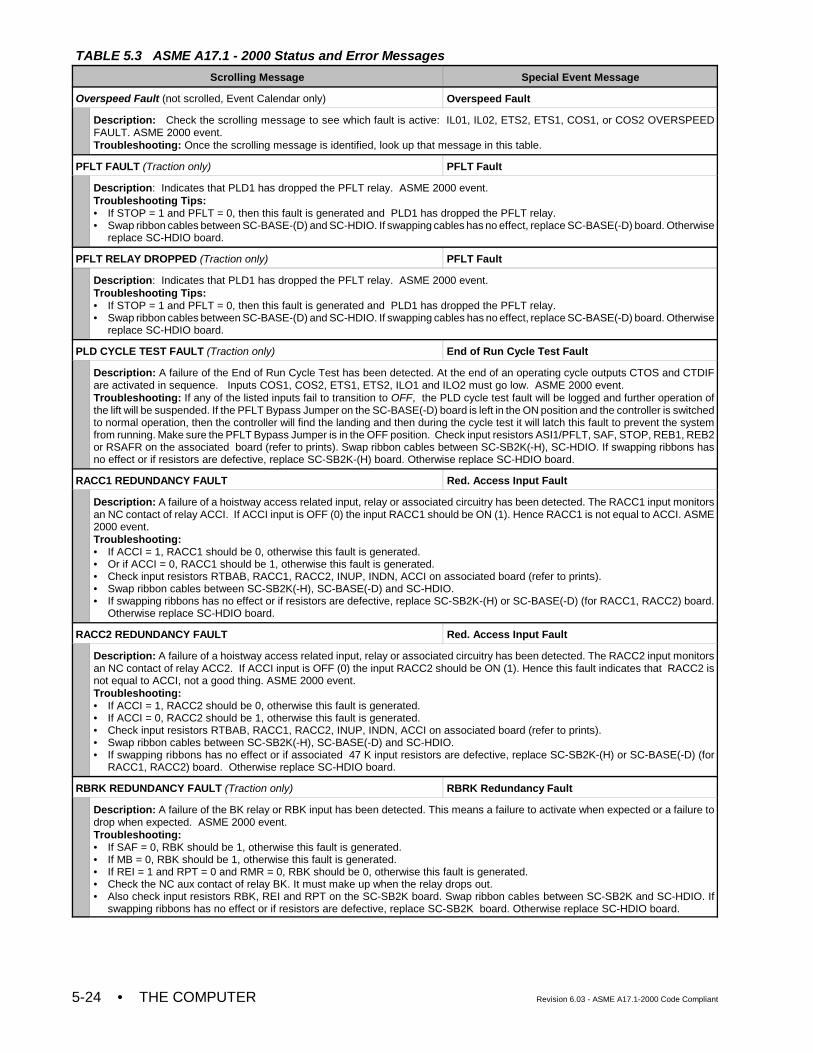
TABLE 5.3 ASME A17.1 - 2000 Status and Error Messages
Scrolling Message Special Event Message
• THE COMPUTER Revision 6.03 - ASME A17.1-2000 Code Compliant5-24
Overspeed Fault (not scrolled, Event Calendar only) Overspeed Fault
Description: Check the scrolling message to see which fault is active: IL01, IL02, ETS2, ETS1, COS1, or COS2 OVERSPEEDFAULT. ASME 2000 event.Troubleshooting: Once the scrolling message is identified, look up that message in this table.
PFLT FAULT (Traction only) PFLT Fault
Description: Indicates that PLD1 has dropped the PFLT relay. ASME 2000 event.Troubleshooting Tips:• If STOP = 1 and PFLT = 0, then this fault is generated and PLD1 has dropped the PFLT relay.• Swap ribbon cables between SC-BASE-(D) and SC-HDIO. If swapping cables has no effect, replace SC-BASE(-D) board. Otherwise
replace SC-HDIO board.
PFLT RELAY DROPPED (Traction only) PFLT Fault
Description: Indicates that PLD1 has dropped the PFLT relay. ASME 2000 event.Troubleshooting Tips:• If STOP = 1 and PFLT = 0, then this fault is generated and PLD1 has dropped the PFLT relay.• Swap ribbon cables between SC-BASE-(D) and SC-HDIO. If swapping cables has no effect, replace SC-BASE(-D) board. Otherwise
replace SC-HDIO board.
PLD CYCLE TEST FAULT (Traction only) End of Run Cycle Test Fault
Description: A failure of the End of Run Cycle Test has been detected. At the end of an operating cycle outputs CTOS and CTDIFare activated in sequence. Inputs COS1, COS2, ETS1, ETS2, ILO1 and ILO2 must go low. ASME 2000 event.Troubleshooting: If any of the listed inputs fail to transition to OFF, the PLD cycle test fault will be logged and further operation ofthe lift will be suspended. If the PFLT Bypass Jumper on the SC-BASE(-D) board is left in the ON position and the controller is switchedto normal operation, then the controller will find the landing and then during the cycle test it will latch this fault to prevent the systemfrom running. Make sure the PFLT Bypass Jumper is in the OFF position. Check input resistors ASI1/PFLT, SAF, STOP, REB1, REB2or RSAFR on the associated board (refer to prints). Swap ribbon cables between SC-SB2K(-H), SC-HDIO. If swapping ribbons hasno effect or if resistors are defective, replace SC-SB2K-(H) board. Otherwise replace SC-HDIO board.
RACC1 REDUNDANCY FAULT Red. Access Input Fault
Description: A failure of a hoistway access related input, relay or associated circuitry has been detected. The RACC1 input monitorsan NC contact of relay ACCI. If ACCI input is OFF (0) the input RACC1 should be ON (1). Hence RACC1 is not equal to ACCI. ASME2000 event.Troubleshooting: • If ACCI = 1, RACC1 should be 0, otherwise this fault is generated.• Or if ACCI = 0, RACC1 should be 1, otherwise this fault is generated.• Check input resistors RTBAB, RACC1, RACC2, INUP, INDN, ACCI on associated board (refer to prints). • Swap ribbon cables between SC-SB2K(-H), SC-BASE(-D) and SC-HDIO. • If swapping ribbons has no effect or if resistors are defective, replace SC-SB2K-(H) or SC-BASE(-D) (for RACC1, RACC2) board.
Otherwise replace SC-HDIO board.
RACC2 REDUNDANCY FAULT Red. Access Input Fault
Description: A failure of a hoistway access related input, relay or associated circuitry has been detected. The RACC2 input monitorsan NC contact of relay ACC2. If ACCI input is OFF (0) the input RACC2 should be ON (1). Hence this fault indicates that RACC2 isnot equal to ACCI, not a good thing. ASME 2000 event.Troubleshooting: • If ACCI = 1, RACC2 should be 0, otherwise this fault is generated.• If ACCI = 0, RACC2 should be 1, otherwise this fault is generated.• Check input resistors RTBAB, RACC1, RACC2, INUP, INDN, ACCI on associated board (refer to prints). • Swap ribbon cables between SC-SB2K(-H), SC-BASE(-D) and SC-HDIO. • If swapping ribbons has no effect or if associated 47 K input resistors are defective, replace SC-SB2K-(H) or SC-BASE(-D) (for
RACC1, RACC2) board. Otherwise replace SC-HDIO board.
RBRK REDUNDANCY FAULT (Traction only) RBRK Redundancy Fault
Description: A failure of the BK relay or RBK input has been detected. This means a failure to activate when expected or a failure todrop when expected. ASME 2000 event.Troubleshooting:• If SAF = 0, RBK should be 1, otherwise this fault is generated.• If MB = 0, RBK should be 1, otherwise this fault is generated.• If REI = 1 and RPT = 0 and RMR = 0, RBK should be 0, otherwise this fault is generated.• Check the NC aux contact of relay BK. It must make up when the relay drops out.• Also check input resistors RBK, REI and RPT on the SC-SB2K board. Swap ribbon cables between SC-SB2K and SC-HDIO. If
swapping ribbons has no effect or if resistors are defective, replace SC-SB2K board. Otherwise replace SC-HDIO board.
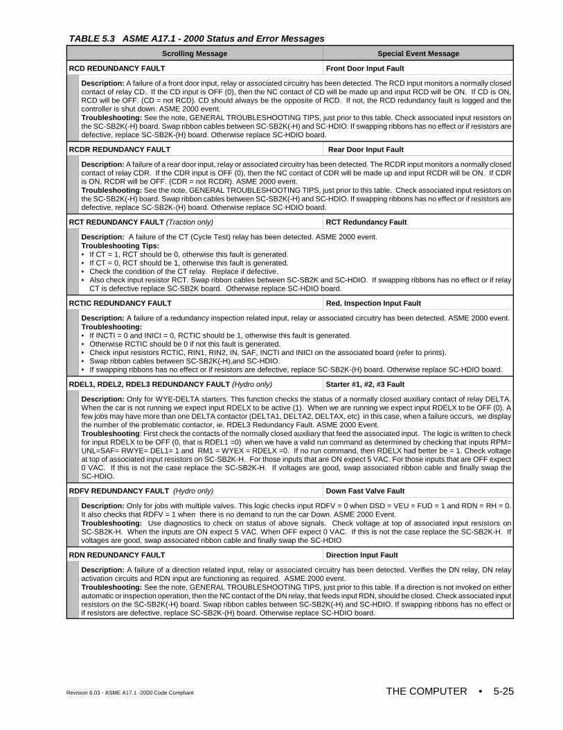
TABLE 5.3 ASME A17.1 - 2000 Status and Error Messages
Scrolling Message Special Event Message
Revision 6.03 - ASME A17.1 -2000 Code Compliant THE COMPUTER • 5-25
RCD REDUNDANCY FAULT Front Door Input Fault
Description: A failure of a front door input, relay or associated circuitry has been detected. The RCD input monitors a normally closedcontact of relay CD. If the CD input is OFF (0), then the NC contact of CD will be made up and input RCD will be ON. If CD is ON,RCD will be OFF. (CD = not RCD). CD should always be the opposite of RCD. If not, the RCD redundancy fault is logged and thecontroller is shut down. ASME 2000 event.Troubleshooting: See the note, GENERAL TROUBLESHOOTING TIPS, just prior to this table. Check associated input resistors onthe SC-SB2K(-H) board. Swap ribbon cables between SC-SB2K(-H) and SC-HDIO. If swapping ribbons has no effect or if resistors aredefective, replace SC-SB2K-(H) board. Otherwise replace SC-HDIO board.
RCDR REDUNDANCY FAULT Rear Door Input Fault
Description: A failure of a rear door input, relay or associated circuitry has been detected. The RCDR input monitors a normally closedcontact of relay CDR. If the CDR input is OFF (0), then the NC contact of CDR will be made up and input RCDR will be ON. If CDRis ON, RCDR will be OFF. (CDR = not RCDR). ASME 2000 event.Troubleshooting: See the note, GENERAL TROUBLESHOOTING TIPS, just prior to this table. Check associated input resistors onthe SC-SB2K(-H) board. Swap ribbon cables between SC-SB2K(-H) and SC-HDIO. If swapping ribbons has no effect or if resistors aredefective, replace SC-SB2K-(H) board. Otherwise replace SC-HDIO board.
RCT REDUNDANCY FAULT (Traction only) RCT Redundancy Fault
Description: A failure of the CT (Cycle Test) relay has been detected. ASME 2000 event.Troubleshooting Tips:• If CT = 1, RCT should be 0, otherwise this fault is generated.• If CT = 0, RCT should be 1, otherwise this fault is generated.• Check the condition of the CT relay. Replace if defective.• Also check input resistor RCT. Swap ribbon cables between SC-SB2K and SC-HDIO. If swapping ribbons has no effect or if relay
CT is defective replace SC-SB2K board. Otherwise replace SC-HDIO board.
RCTIC REDUNDANCY FAULT Red. Inspection Input Fault
Description: A failure of a redundancy inspection related input, relay or associated circuitry has been detected. ASME 2000 event.Troubleshooting: • If INCTI = 0 and INICI = 0, RCTIC should be 1, otherwise this fault is generated.• Otherwise RCTIC should be 0 if not this fault is generated.• Check input resistors RCTIC, RIN1, RIN2, IN, SAF, INCTI and INICI on the associated board (refer to prints). • Swap ribbon cables between SC-SB2K(-H),and SC-HDIO.• If swapping ribbons has no effect or if resistors are defective, replace SC-SB2K-(H) board. Otherwise replace SC-HDIO board.
RDEL1, RDEL2, RDEL3 REDUNDANCY FAULT (Hydro only) Starter #1, #2, #3 Fault
Description: Only for WYE-DELTA starters. This function checks the status of a normally closed auxiliary contact of relay DELTA.When the car is not running we expect input RDELX to be active (1). When we are running we expect input RDELX to be OFF (0). Afew jobs may have more than one DELTA contactor (DELTA1, DELTA2, DELTAX, etc) in this case, when a failure occurs, we displaythe number of the problematic contactor, ie. RDEL3 Redundancy Fault. ASME 2000 Event.Troubleshooting: First check the contacts of the normally closed auxiliary that feed the associated input. The logic is written to checkfor input RDELX to be OFF (0, that is RDEL1 =0) when we have a valid run command as determined by checking that inputs RPM=UNL=SAF= RWYE= DEL1= 1 and RM1 = WYEX = RDELX =0. If no run command, then RDELX had better be = 1. Check voltageat top of associated input resistors on SC-SB2K-H. For those inputs that are ON expect 5 VAC. For those inputs that are OFF expect0 VAC. If this is not the case replace the SC-SB2K-H. If voltages are good, swap associated ribbon cable and finally swap theSC-HDIO.
RDFV REDUNDANCY FAULT (Hydro only) Down Fast Valve Fault
Description: Only for jobs with multiple valves. This logic checks input RDFV = 0 when DSD = VEU = FUD = 1 and RDN = RH = 0.It also checks that RDFV = 1 when there is no demand to run the car Down. ASME 2000 Event.Troubleshooting: Use diagnostics to check on status of above signals. Check voltage at top of associated input resistors onSC-SB2K-H. When the inputs are ON expect 5 VAC. When OFF expect 0 VAC. If this is not the case replace the SC-SB2K-H. Ifvoltages are good, swap associated ribbon cable and finally swap the SC-HDIO
RDN REDUNDANCY FAULT Direction Input Fault
Description: A failure of a direction related input, relay or associated circuitry has been detected. Verifies the DN relay, DN relayactivation circuits and RDN input are functioning as required. ASME 2000 event.Troubleshooting: See the note, GENERAL TROUBLESHOOTING TIPS, just prior to this table. If a direction is not invoked on eitherautomatic or inspection operation, then the NC contact of the DN relay, that feeds input RDN, should be closed. Check associated inputresistors on the SC-SB2K(-H) board. Swap ribbon cables between SC-SB2K(-H) and SC-HDIO. If swapping ribbons has no effect orif resistors are defective, replace SC-SB2K-(H) board. Otherwise replace SC-HDIO board.
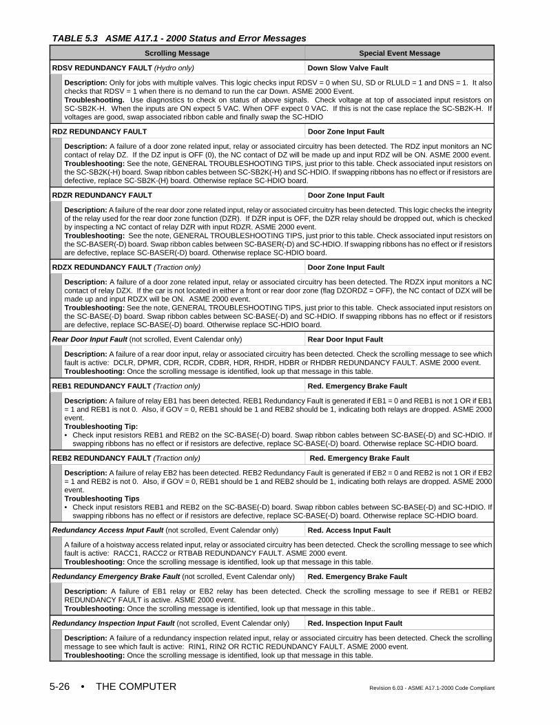
TABLE 5.3 ASME A17.1 - 2000 Status and Error Messages
Scrolling Message Special Event Message
• THE COMPUTER Revision 6.03 - ASME A17.1-2000 Code Compliant5-26
RDSV REDUNDANCY FAULT (Hydro only) Down Slow Valve Fault
Description: Only for jobs with multiple valves. This logic checks input RDSV = 0 when SU, SD or RLULD = 1 and DNS = 1. It alsochecks that RDSV = 1 when there is no demand to run the car Down. ASME 2000 Event. Troubleshooting. Use diagnostics to check on status of above signals. Check voltage at top of associated input resistors onSC-SB2K-H. When the inputs are ON expect 5 VAC. When OFF expect 0 VAC. If this is not the case replace the SC-SB2K-H. Ifvoltages are good, swap associated ribbon cable and finally swap the SC-HDIO
RDZ REDUNDANCY FAULT Door Zone Input Fault
Description: A failure of a door zone related input, relay or associated circuitry has been detected. The RDZ input monitors an NCcontact of relay DZ. If the DZ input is OFF (0), the NC contact of DZ will be made up and input RDZ will be ON. ASME 2000 event.Troubleshooting: See the note, GENERAL TROUBLESHOOTING TIPS, just prior to this table. Check associated input resistors onthe SC-SB2K(-H) board. Swap ribbon cables between SC-SB2K(-H) and SC-HDIO. If swapping ribbons has no effect or if resistors aredefective, replace SC-SB2K-(H) board. Otherwise replace SC-HDIO board.
RDZR REDUNDANCY FAULT Door Zone Input Fault
Description: A failure of the rear door zone related input, relay or associated circuitry has been detected. This logic checks the integrityof the relay used for the rear door zone function (DZR). If DZR input is OFF, the DZR relay should be dropped out, which is checkedby inspecting a NC contact of relay DZR with input RDZR. ASME 2000 event. Troubleshooting: See the note, GENERAL TROUBLESHOOTING TIPS, just prior to this table. Check associated input resistors onthe SC-BASER(-D) board. Swap ribbon cables between SC-BASER(-D) and SC-HDIO. If swapping ribbons has no effect or if resistorsare defective, replace SC-BASER(-D) board. Otherwise replace SC-HDIO board.
RDZX REDUNDANCY FAULT (Traction only) Door Zone Input Fault
Description: A failure of a door zone related input, relay or associated circuitry has been detected. The RDZX input monitors a NCcontact of relay DZX. If the car is not located in either a front or rear door zone (flag DZORDZ = OFF), the NC contact of DZX will bemade up and input RDZX will be ON. ASME 2000 event.Troubleshooting: See the note, GENERAL TROUBLESHOOTING TIPS, just prior to this table. Check associated input resistors onthe SC-BASE(-D) board. Swap ribbon cables between SC-BASE(-D) and SC-HDIO. If swapping ribbons has no effect or if resistorsare defective, replace SC-BASE(-D) board. Otherwise replace SC-HDIO board.
Rear Door Input Fault (not scrolled, Event Calendar only) Rear Door Input Fault
Description: A failure of a rear door input, relay or associated circuitry has been detected. Check the scrolling message to see whichfault is active: DCLR, DPMR, CDR, RCDR, CDBR, HDR, RHDR, HDBR or RHDBR REDUNDANCY FAULT. ASME 2000 event.Troubleshooting: Once the scrolling message is identified, look up that message in this table.
REB1 REDUNDANCY FAULT (Traction only) Red. Emergency Brake Fault
Description: A failure of relay EB1 has been detected. REB1 Redundancy Fault is generated if EB1 = 0 and REB1 is not 1 OR if EB1= 1 and REB1 is not 0. Also, if GOV = 0, REB1 should be 1 and REB2 should be 1, indicating both relays are dropped. ASME 2000event.Troubleshooting Tip:• Check input resistors REB1 and REB2 on the SC-BASE(-D) board. Swap ribbon cables between SC-BASE(-D) and SC-HDIO. If
swapping ribbons has no effect or if resistors are defective, replace SC-BASE(-D) board. Otherwise replace SC-HDIO board.
REB2 REDUNDANCY FAULT (Traction only) Red. Emergency Brake Fault
Description: A failure of relay EB2 has been detected. REB2 Redundancy Fault is generated if EB2 = 0 and REB2 is not 1 OR if EB2= 1 and REB2 is not 0. Also, if GOV = 0, REB1 should be 1 and REB2 should be 1, indicating both relays are dropped. ASME 2000event.Troubleshooting Tips• Check input resistors REB1 and REB2 on the SC-BASE(-D) board. Swap ribbon cables between SC-BASE(-D) and SC-HDIO. If
swapping ribbons has no effect or if resistors are defective, replace SC-BASE(-D) board. Otherwise replace SC-HDIO board.
Redundancy Access Input Fault (not scrolled, Event Calendar only) Red. Access Input Fault
A failure of a hoistway access related input, relay or associated circuitry has been detected. Check the scrolling message to see whichfault is active: RACC1, RACC2 or RTBAB REDUNDANCY FAULT. ASME 2000 event.Troubleshooting: Once the scrolling message is identified, look up that message in this table.
Redundancy Emergency Brake Fault (not scrolled, Event Calendar only) Red. Emergency Brake Fault
Description: A failure of EB1 relay or EB2 relay has been detected. Check the scrolling message to see if REB1 or REB2REDUNDANCY FAULT is active. ASME 2000 event.Troubleshooting: Once the scrolling message is identified, look up that message in this table..
Redundancy Inspection Input Fault (not scrolled, Event Calendar only) Red. Inspection Input Fault
Description: A failure of a redundancy inspection related input, relay or associated circuitry has been detected. Check the scrollingmessage to see which fault is active: RIN1, RIN2 OR RCTIC REDUNDANCY FAULT. ASME 2000 event.Troubleshooting: Once the scrolling message is identified, look up that message in this table.
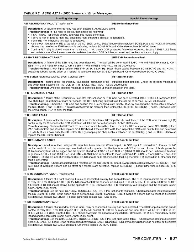
TABLE 5.3 ASME A17.1 - 2000 Status and Error Messages
Scrolling Message Special Event Message
Revision 6.03 - ASME A17.1 -2000 Code Compliant THE COMPUTER • 5-27
REI REDUNDANCY FAULT (Traction only) REI Redundancy Fault
Description: A failure of the RE relay has been detected. ASME 2000 event.Troubleshooting: If FLT relay is picked, then check the following:• If SAF is low, REI should be low, otherwise this fault is generated.• If UPS is high or DNS is high, REI should be high, otherwise this fault is generated.• Verify REI = 0, otherwise this fault is generated.• Also check input resistor REI at top left of the SC-SB2K board. Swap ribbon cables between SC-SB2K and SC-HDIO. If swapping
ribbons has no effect or if REI resistor is defective, replace SC-SB2K board. Otherwise replace SC-HDIO board.• Confirm FLT relay is picked when a run is initiated. If not, then a DDP generated failure has occurred. Bypass ASME A17.1 faults
and initiate a run. Check event calendar to determine which DDP fault has occurred and troubleshoot accordingly.
RESBYP REDUNDANCY FAULT RESBYP Redundancy Fault
Description: A failure of the ESB relay has been detected. The fault will be generated if SAFC = 0 and RESBYP is not 1, OR ifESBYP = 1 and RESBYP is not 0, OR if ESBYP = 0 and RESBYP is not 1. ASME 2000 event.Troubleshooting: Check input resistor RESBYP on SC-SB2K(-H). Swap ribbon cables between SC-SB2K(-H) and SC-HDIO. Ifswapping ribbons has no effect or if resistor is defective, replace SC-SB2K-(H) board. Otherwise replace SC-HDIO board.
RFR Button Fault (not scrolled, Event Calendar only) RFR Button Fault
Description: A failure of the Redundancy Fault Reset Pushbutton or RFR input has been detected. Check the scrolling message tosee which fault is active: RFR STUCK or RFR FLICKERING FAULT. ASME 2000 event.Troubleshooting: Once the scrolling message is identified, look up that message in this table.
RFR FLICKERING FAULT RFR Button Fault
Description: A failure of the Redundancy Fault Reset Pushbutton or RFR input has been detected. If the RFR input transitions fromlow (0) to high (1) six times or more per second, the RFR flickering fault will take the car out of service. ASME 2000 event. Troubleshooting: Check the RFR input and confirm that it is changing state rapidly. If so, try swapping the ribbon cables betweenthe SC-SB2K(-H) and SC-HDIO. If this does not correct the problem, then replace the SC-HDIO / SC-SB2K(-H) board. Otherwise resetthe swing panel / PCA to clear the fault.
RFR STUCK FAULT RFR Button Fault
Description: A failure of the Redundancy Fault Reset Pushbutton or RFR input has been detected. If the RFR input remains high (1)continuously for 30 seconds the RFR stuck fault will take the car out of service. ASME 2000 event.Troubleshooting: Confirm that RFR = 1. To determine which board has failed, check the RFR resistor on board SC-SB2K(-H) for 0VAC on the bottom end, if so then replace SC-HDIO board. If there is 120 VAC, then inspect the EBR reset pushbutton and determineif it is truly stuck, if so replace the SC-SB2K(-H). Try swapping the ribbon cables between the SC-SB2K(-H) and SC-HDIO. Otherwisereplace the SC-SB2K(-H) board.
RH REDUNDANCY FAULT Front Door Input Fault
Description: A failure of the H relay or RH input has been detected.When output H is OFF, input RH should be 1. If relay H's NOcontacts weld closed, the monitoring contact will not make up when the H output is turned OFF at the end of a run. If this happens theRH redundancy fault will be logged and the system shut down.If SAF = 0 and DLK = 0 (28 bit 7), RH should be 1, otherwise this faultis generated.If H = 1 and RLULD = 1 and RIN2 = 0 AND there is an intent to move up/down UP - if UNL = 1 and RUP = 0 and USD= 1 DOWN - if DNL = 1 and RDN = 0 and DSD = 1 RH should be 0, otherwise this fault is generated. If RH should be 1, otherwise thisfault is generated.Troubleshooting: Check associated input resistors on the SC-SB2K(-H) board. Swap ribbon cables between SC-SB2K(-H) andSC-HDIO. If swapping ribbons has no effect or if resistors are defective, replace SC-SB2K(-H) board. Otherwise replace SC-HDIOboard.
RHD REDUNDANCY FAULT (Traction only) Front Door Input Fault
Description: A failure of a front door input, relay or associated circuitry has been detected. The RHD input monitors an NC contactof relay HD. If the HD input is OFF (0), the NC contact of HD will be made up and input RHD will be ON. If HD is ON, RHD will be OFF(HD = not RHD). HD should always be the opposite of RHD. Otherwise, the RHD redundancy fault is logged and the controller is shutdown. ASME 2000 event.Troubleshooting: See the note, GENERAL TROUBLESHOOTING TIPS, just prior to this table. Check associated input resistors onthe SC-SB2K(-H) board. Swap ribbon cables between SC-SB2K(-H) and SC-HDIO. If swapping ribbons has no effect or if resistorsare defective, replace SC-SB2K(-H) board. Otherwise replace SC-HDIO board.
RHDB REDUNDANCY FAULT Front Door Input Fault
Description: A failure of a front door bypass input, relay or associated circuitry has been detected. The RHDB input monitors an NCcontact of relay HDB. If the HDB input is OFF (0), the NC contact of HDB will be made up and input RHDB will be ON. If HDB is ON,RHDB will be OFF (HDB = not RHDB). HDB should always be the opposite of input RHDB. Otherwise, the RHDB redundancy fault islogged and the controller is shut down. ASME 2000 event.Troubleshooting: See the note, GENERAL TROUBLESHOOTING TIPS, just prior to this table. Check associated input resistorson the SC-BASE(-D) board. Swap ribbon cables between SC-BASE(-D) and SC-HDIO. If swapping ribbons has no effect or if resistorsare defective, replace SC-BASE(-D) board. Otherwise replace SC-HDIO board.
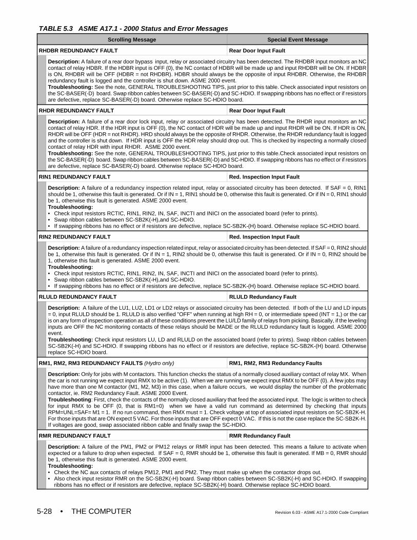
TABLE 5.3 ASME A17.1 - 2000 Status and Error Messages
Scrolling Message Special Event Message
• THE COMPUTER Revision 6.03 - ASME A17.1-2000 Code Compliant5-28
RHDBR REDUNDANCY FAULT Rear Door Input Fault
Description: A failure of a rear door bypass input, relay or associated circuitry has been detected. The RHDBR input monitors an NCcontact of relay HDBR. If the HDBR input is OFF (0), the NC contact of HDBR will be made up and input RHDBR will be ON. If HDBRis ON, RHDBR will be OFF (HDBR = not RHDBR). HDBR should always be the opposite of input RHDBR. Otherwise, the RHDBRredundancy fault is logged and the controller is shut down. ASME 2000 event.Troubleshooting: See the note, GENERAL TROUBLESHOOTING TIPS, just prior to this table. Check associated input resistors onthe SC-BASER(-D) board. Swap ribbon cables between SC-BASER(-D) and SC-HDIO. If swapping ribbons has no effect or if resistorsare defective, replace SC-BASER(-D) board. Otherwise replace SC-HDIO board.
RHDR REDUNDANCY FAULT Rear Door Input Fault
Description: A failure of a rear door lock input, relay or associated circuitry has been detected. The RHDR input monitors an NCcontact of relay HDR. If the HDR input is OFF (0), the NC contact of HDR will be made up and input RHDR will be ON. If HDR is ON,RHDR will be OFF (HDR = not RHDR). HRD should always be the opposite of RHDR. Otherwise, the RHDR redundancy fault is loggedand the controller is shut down. If HDR input is OFF the HDR relay should drop out. This is checked by inspecting a normally closedcontact of relay HDR with input RHDR. ASME 2000 event.Troubleshooting: See the note, GENERAL TROUBLESHOOTING TIPS, just prior to this table.Check associated input resistors onthe SC-BASER(-D) board. Swap ribbon cables between SC-BASER(-D) and SC-HDIO. If swapping ribbons has no effect or if resistorsare defective, replace SC-BASER(-D) board. Otherwise replace SC-HDIO board.
RIN1 REDUNDANCY FAULT Red. Inspection Input Fault
Description: A failure of a redundancy inspection related input, relay or associated circuitry has been detected. If SAF = 0, RIN1should be 1, otherwise this fault is generated. Or if IN = 1, RIN1 should be 0, otherwise this fault is generated. Or if IN = 0, RIN1 shouldbe 1, otherwise this fault is generated. ASME 2000 event.Troubleshooting:• Check input resistors RCTIC, RIN1, RIN2, IN, SAF, INCTI and INICI on the associated board (refer to prints). • Swap ribbon cables between SC-SB2K(-H),and SC-HDIO.• If swapping ribbons has no effect or if resistors are defective, replace SC-SB2K-(H) board. Otherwise replace SC-HDIO board.
RIN2 REDUNDANCY FAULT Red. Inspection Input Fault
Description: A failure of a redundancy inspection related input, relay or associated circuitry has been detected. If SAF = 0, RIN2 shouldbe 1, otherwise this fault is generated. Or if IN = 1, RIN2 should be 0, otherwise this fault is generated. Or if IN = 0, RIN2 should be1, otherwise this fault is generated. ASME 2000 event.Troubleshooting:• Check input resistors RCTIC, RIN1, RIN2, IN, SAF, INCTI and INICI on the associated board (refer to prints). • Swap ribbon cables between SC-SB2K(-H),and SC-HDIO.• If swapping ribbons has no effect or if resistors are defective, replace SC-SB2K-(H) board. Otherwise replace SC-HDIO board.
RLULD REDUNDANCY FAULT RLULD Redundancy Fault
Description: A failure of the LU1, LU2, LD1 or LD2 relays or associated circuitry has been detected. If both of the LU and LD inputs= 0, input RLULD should be 1. RLULD is also verified "OFF" when running at high RH = 0, or intermediate speed (INT = 1,) or the caris on any form of inspection operation as all of these conditions prevent the LU/LD family of relays from picking. Basically, if the levelinginputs are OFF the NC monitoring contacts of these relays should be MADE or the RLULD redundancy fault is logged. ASME 2000event.Troubleshooting: Check input resistors LU, LD and RLULD on the associated board (refer to prints). Swap ribbon cables betweenSC-SB2K(-H) and SC-HDIO. If swapping ribbons has no effect or if resistors are defective, replace SC-SB2K-(H) board. Otherwisereplace SC-HDIO board.
RM1, RM2, RM3 REDUNDANCY FAULTS (Hydro only) RM1, RM2, RM3 Redundancy Faults
Description: Only for jobs with M contactors. This function checks the status of a normally closed auxiliary contact of relay MX. Whenthe car is not running we expect input RMX to be active (1). When we are running we expect input RMX to be OFF (0). A few jobs mayhave more than one M contactor (M1, M2, M3) in this case, when a failure occurs, we would display the number of the problematiccontactor, ie. RM2 Redundancy Fault. ASME 2000 Event.Troubleshooting: First, check the contacts of the normally closed auxiliary that feed the associated input. The logic is written to checkfor input RMX to be OFF (0, that is RM1=0) when we have a valid run command as determined by checking that inputsRPM=UNL=SAF= M1 = 1. If no run command, then RMX must = 1. Check voltage at top of associated input resistors on SC-SB2K-H.For those inputs that are ON expect 5 VAC. For those inputs that are OFF expect 0 VAC. If this is not the case replace the SC-SB2K-H.If voltages are good, swap associated ribbon cable and finally swap the SC-HDIO.
RMR REDUNDANCY FAULT RMR Redundancy Fault
Description: A failure of the PM1, PM2 or PM12 relays or RMR input has been detected. This means a failure to activate whenexpected or a failure to drop when expected. If SAF = 0, RMR should be 1, otherwise this fault is generated. If MB = 0, RMR shouldbe 1, otherwise this fault is generated. ASME 2000 event.Troubleshooting:• Check the NC aux contacts of relays PM12, PM1 and PM2. They must make up when the contactor drops out.• Also check input resistor RMR on the SC-SB2K(-H) board. Swap ribbon cables between SC-SB2K(-H) and SC-HDIO. If swapping
ribbons has no effect or if resistors are defective, replace SC-SB2K(-H) board. Otherwise replace SC-HDIO board.
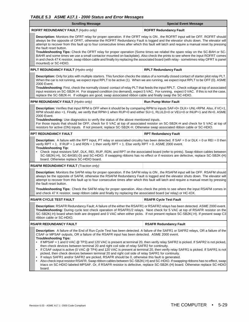
TABLE 5.3 ASME A17.1 - 2000 Status and Error Messages
Scrolling Message Special Event Message
Revision 6.03 - ASME A17.1 -2000 Code Compliant THE COMPUTER • 5-29
ROFRT REDUNDANCY FAULT (Hydro only) ROFRT Redundancy Fault
Description: Monitors the OFRT relay for proper operation. If the OFRT relay is ON , the ROFRT input will be OFF. ROFRT shouldalways be the opposite of OFRT, otherwise the ROFRT Redundancy Fault is logged and the elevator shuts down. The elevator willattempt to recover from this fault up to four consecutive times after which this fault will latch and require a manual reset by pressingthe fault reset button.Troubleshooting Tips: Check the OFRT relay for proper operation (Some times we relabel the spare relay on the SC-BAH or SC-BAHR and some times we use a small contactor mounted on backplate). Also check the prints to see where the input ROFRT comesin and check 47 K resistor, swap ribbon cable and finally try replacing the associated board (with relay - sometimes relay OFRT is panelmounted) or SC-HDIO.
RPLT REDUNDANCY FAULT (Hydro only) RPLT Redundancy Fault
Description: Only for jobs with multiple starters. This function checks the status of a normally closed contact of starter pilot relay PLT.When the car is not running, we expect input RPLT to be active (1). When we are running, we expect input RPLT to be OFF (0). ASME2000 Event.Troubleshooting: First, check the normally closed contact of relay PLT that feeds the input RPLT. Check voltage at top of associatedinput resistors on SC-SB2K-H. For stopped condition (no demand), expect 5 VAC. For running, expect 0 VAC. If this is not the case,replace the SC-SB2K-H. If voltages are good, swap associated ribbon cable and finally swap the SC-HDIO.
RPM REDUNDANCY FAULT (Hydro only) Run Pump Motor Fault
Description: Verifies that input RPM is OFF when it should be by comparing RPM to inputs SAF=0= DLK= UNL=RPM. Also, if VC=1,RPM should also =1. Finally, we verify that RPM=1 when RUP=0 and either SU=1, RLULD=0 or VEU=0 or INUP=1 and IN=0. ASME2000 Event. Troubleshooting: Use diagnostics to verify the status of the above mentioned inputs. For those inputs that should be OFF, check for 0 VAC at top of associated resistor on SC-SB2K-H and check for 5 VAC at top ofresistors for active (ON) inputs. If not present, replace SC-SB2K-H. Otherwise swap associated ribbon cable or SC-HDIO.
RPT REDUNDANCY FAULT RPT Redundancy Fault
Description: A failure with the RPT input, PT relay or associated circuitry has been detected. If SAF = 0 or DLK = 0 or REI = 0 thenverify RPT = 1. If RUP = 1 and RDN = 1 then verify RPT = 1. Else verify RPT = 0. ASME 2000 event.Troubleshooting Tip:• Check input resistors SAF, DLK, REI, RUP, RDN, and RPT on the associated board (refer to prints). Swap ribbon cables between
SC-SB2K(-H), SC-BASE(-D) and SC-HDIO. If swapping ribbons has no effect or if resistors are defective, replace SC-SB2K-(H)board. Otherwise replace SC-HDIO board.
RSAFM REDUNDANCY FAULT (Traction only)
Description: Monitors the SAFM relay for proper operation. If the SAFM relay is ON , the RSAFM input will be OFF. RSAFM shouldalways be the opposite of SAFM, otherwise the RSAFM Redundancy Fault is logged and the elevator shuts down. The elevator willattempt to recover from this fault up to four consecutive times after which this fault will latch and require a manual reset by pressingthe fault reset button.
Troubleshooting Tips: Check the SAFM relay for proper operation. Also check the prints to see where the input RSAFM comes inand check 47 K resistor, swap ribbon cable and finally try replacing the associated board (w/ relay) or HC-IOX.
RSAFR CYCLE TEST FAULT RSAFR Cycle Test Fault
Description: RSAFR Redundancy Fault; A failure of the either the RSAFR1 or RSAFR2 relays has been detected. ASME 2000 event.Troubleshooting: During cycle test check operation of RSAFR1/2 relays. Next check for 5 VAC at top of RSAFR resistor on theSC-SB2K(-H) board when both are dropped and 0 VAC when either picks. If not present replace SC-SB2K(-H). If present swap C3ribbon cable or SC-HDIO.
RSAFR REDUNDANCY FAULT RSAFR Redundancy Fault
Description: A failure of the End of Run Cycle Test has been detected. A failure of the SAFR1 or SAFR2 relays, OR a failure of theCSAF or MPSAF outputs, OR a failure of the RSAFR input has been detected. ASME 2000 event.Troubleshooting Tips:• If MPSAF = 1 and 0 VAC @ TP3) and 120 VAC is present at terminal 20, then verify relay SAFR2 is picked. If SAFR2 is not picked,
then check devices between terminal 20 and right coil side of relay SAFR2 for continuity.• If CSAF output is active (0 VAC @ TP4) and 120 VAC is present at terminal 20, then verify relay SAFR1 is picked. If SAFR1 is not
picked, then check devices between terminal 20 and right coil side of relay SAFR1 for continuity.• If relays SAFR1 and/or SAFR2 are picked, RSAFR should be 0, otherwise this fault is generated. • Also check input resistor RSAFR. Swap ribbon cables between SC-SB2K(-H) and SC-HDIO. If swapping ribbons has no effect, swap
triacs on SC-HDIO labeled MPSAF. Or, if RSAFR resistor is defective, replace SC-SB2K-(H) board. Otherwise replace SC-HDIOboard.
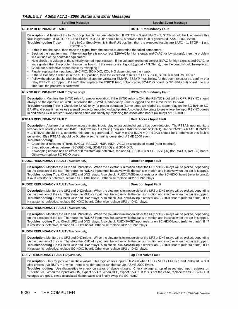
TABLE 5.3 ASME A17.1 - 2000 Status and Error Messages
Scrolling Message Special Event Message
• THE COMPUTER Revision 6.03 - ASME A17.1-2000 Code Compliant5-30
RSTOP REDUNDANCY FAULT RSTOP Redundancy Fault
Description: A failure of the In Car Stop Switch has been detected. If RSTOP = 0 and SAFC = 1, STOP should be 1, otherwise thisfault is generated. If RSTOP = 1 and ESBYP = 0, STOP should be 0, otherwise this fault is generated. ASME 2000 event.Troubleshooting Tips:• If the In Car Stop Switch is in the RUN position, then the expected results are SAFC = 1, STOP = 1 and
RSTOP = 0. • If this is not the case, then trace the signal from the source to determine the failed component. • Begin at the input terminal. If the voltage here is not correct (120VAC for high signals and 0VAC for low signals), then the problem
lies outside of the controller equipment.• Next check the voltage at the similarly named input resistor. If the voltage here is not correct (5VAC for high signals and 0VAC for
low signals), then the problem lies on this board. If the resistor is still good (typically 47kOhms), then the board should be replaced.• Check for a defective ribbon cable by swapping it.• Finally, replace the input board (HC-PIO, SC-HDIO, IOX, I4O depending on the input).• If the In Car Stop Switch is in the STOP position, then the expected results are ESBYP = 0, STOP = 0 and RSTOP = 1.• Follow the above checks with the additional step for validating ESBYP. ESBYP must be low for this event to occur so, confirm that
relay ESBYP is dropped. If it isn’t, then replace the ESBYP triac, ribbon cable, SC-HDIO board, or SC-SB2K(-H) board one at atime until the problem is corrected.
RSYNC REDUNDANCY FAULT (Hydro only) RSYNC Redundancy Fault
Description: Monitors the SYNC relay for proper operation. If the SYNC relay is ON , the RSYNC input will be OFF. RSYNC shouldalways be the opposite of SYNC, otherwise the RSYNC Redundancy Fault is logged and the elevator shuts down.Troubleshooting Tips: : Check the SYNC relay for proper operation (Some times we relabel the spare relay on the SC-BAH or SC-BAHR and some times we use a small contactor mounted on backplate). Also check the prints to see where the input RSYNC comesin and check 47 K resistor, swap ribbon cable and finally try replacing the associated board (w/ relay) or SC-HDIO.
RTBAB REDUNDANCY FAULT Red. Access Input Fault
Description: A failure of a hoistway access related input, relay or associated circuitry has been detected. The RTBAB input monitorsNC contacts of relays TAB and BAB. If RACC1 input is ON (1) then input RACC2 should be ON (1). Hence RACC1 = RTAB. If RACC1= 1, RTBAB should be 1, otherwise this fault is generated. If INUP = 0 and INDN = 0, RTBAB should be 1, otherwise this fault isgenerated. Else RTBAB should be 0, otherwise this fault is generated. ASME 2000 event.Troubleshooting: • Check input resistors RTBAB, RACC1, RACC2, INUP, INDN, ACCI on associated board (refer to prints). • Swap ribbon cables between SC-SB2K(-H), SC-BASE(-D) and SC-HDIO. • If swapping ribbons has no effect or if resistors are defective, replace SC-SB2K-(H) or SC-BASE(-D) (for RACC1, RACC2) board.
Otherwise replace SC-HDIO board.
RUDX1 REDUNDANCY FAULT (Traction only) Direction Input Fault
Description: Monitors the UP2 and DN2 relays. When the elevator is in motion either the UP2 or DN2 relays will be picked, dependingon the direction of the car. Therefore the RUDX1 input must be active while the car is in motion and inactive when the car is stopped.Troubleshooting Tips: Check UP2 and DN2 relays. Also check RUDX1/ASI5 input resistor on the SC-HDIO board (refer to prints).If 47 K resistor is defective, replace SC-HDIO board. Otherwise replace UP2 or DN2 relays.
RUDX2 REDUNDANCY FAULT (Traction only) Direction Input Fault
Description: Monitors the UP2 and DN2 relays. When the elevator is in motion either the UP2 or DN2 relays will be picked, dependingon the direction of the car. Therefore the RUDX2 input must be active while the car is in motion and inactive when the car is stopped.Troubleshooting Tips: Check UP2 and DN2 relays. Also check RUDX2/ASI6 input resistor on SC-HDIO board (refer to prints). If 47K resistor is defective, replace SC-HDIO board. Otherwise replace UP2 or DN2 relays.
RUDX3 REDUNDANCY FAULT (Traction only)
Description: Monitors the UP2 and DN2 relays. When the elevator is in motion either the UP2 or DN2 relays will be picked, dependingon the direction of the car. Therefore the RUDX3 input must be active while the car is in motion and inactive when the car is stopped.Troubleshooting Tips: Check UP2 and DN2 relays. Also check RUDX3/ASI7 input resistor on SC-HDIO board (refer to prints). If 47K resistor is defective, replace SC-HDIO board. Otherwise replace UP2 or DN2 relays.
RUDX4 REDUNDANCY FAULT (Traction only)
Description: Monitors the UP2 and DN2 relays. When the elevator is in motion either the UP2 or DN2 relays will be picked, dependingon the direction of the car. Therefore the RUDX4 input must be active while the car is in motion and inactive when the car is stopped.Troubleshooting Tips: Check UP2 and DN2 relays. Also check RUDX4/ASI8 input resistor on SC-HDIO board (refer to prints). If 47K resistor is defective, replace SC-HDIO board. Otherwise replace UP2 or DN2 relays.
RUFV REDUNDANCY FAULT (Hydro only) Up Fast Valve Fault
Description: Only for jobs with multiple valves. This logic checks input RUFV = 0 when USD = VEU = FUD = 1 and RUP= RH = 0. Italso checks that RUFV = 1 when there is no demand to run the car Up. ASME 2000 Event.Troubleshooting: Use diagnostics to check on status of above signals. Check voltage at top of associated input resistors onSC-SB2K-H. When the inputs are ON, expect 5 VAC. When OFF, expect 0 VAC. If this is not the case, replace the SC-SB2K-H. Ifvoltages are good, swap associated ribbon cable and finally swap the SC-HDIO
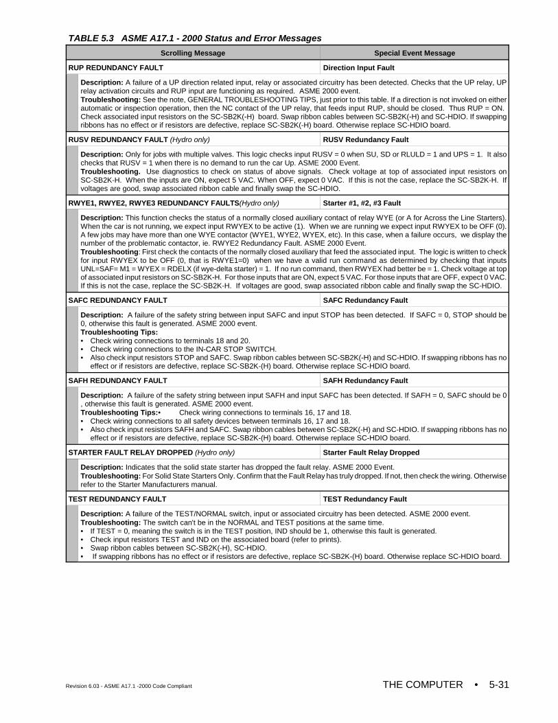
TABLE 5.3 ASME A17.1 - 2000 Status and Error Messages
Scrolling Message Special Event Message
Revision 6.03 - ASME A17.1 -2000 Code Compliant THE COMPUTER • 5-31
RUP REDUNDANCY FAULT Direction Input Fault
Description: A failure of a UP direction related input, relay or associated circuitry has been detected. Checks that the UP relay, UPrelay activation circuits and RUP input are functioning as required. ASME 2000 event.Troubleshooting: See the note, GENERAL TROUBLESHOOTING TIPS, just prior to this table. If a direction is not invoked on eitherautomatic or inspection operation, then the NC contact of the UP relay, that feeds input RUP, should be closed. Thus RUP = ON. Check associated input resistors on the SC-SB2K(-H) board. Swap ribbon cables between SC-SB2K(-H) and SC-HDIO. If swappingribbons has no effect or if resistors are defective, replace SC-SB2K(-H) board. Otherwise replace SC-HDIO board.
RUSV REDUNDANCY FAULT (Hydro only) RUSV Redundancy Fault
Description: Only for jobs with multiple valves. This logic checks input RUSV = 0 when SU, SD or RLULD = 1 and UPS = 1. It alsochecks that RUSV = 1 when there is no demand to run the car Up. ASME 2000 Event. Troubleshooting. Use diagnostics to check on status of above signals. Check voltage at top of associated input resistors onSC-SB2K-H. When the inputs are ON, expect 5 VAC. When OFF, expect 0 VAC. If this is not the case, replace the SC-SB2K-H. Ifvoltages are good, swap associated ribbon cable and finally swap the SC-HDIO.
RWYE1, RWYE2, RWYE3 REDUNDANCY FAULTS(Hydro only) Starter #1, #2, #3 Fault
Description: This function checks the status of a normally closed auxiliary contact of relay WYE (or A for Across the Line Starters).When the car is not running, we expect input RWYEX to be active (1). When we are running we expect input RWYEX to be OFF (0).A few jobs may have more than one WYE contactor (WYE1, WYE2, WYEX, etc). In this case, when a failure occurs, we display thenumber of the problematic contactor, ie. RWYE2 Redundancy Fault. ASME 2000 Event.Troubleshooting: First check the contacts of the normally closed auxiliary that feed the associated input. The logic is written to checkfor input RWYEX to be OFF (0, that is RWYE1=0) when we have a valid run command as determined by checking that inputsUNL=SAF= M1 = WYEX = RDELX (if wye-delta starter) = 1. If no run command, then RWYEX had better be = 1. Check voltage at topof associated input resistors on SC-SB2K-H. For those inputs that are ON, expect 5 VAC. For those inputs that are OFF, expect 0 VAC.If this is not the case, replace the SC-SB2K-H. If voltages are good, swap associated ribbon cable and finally swap the SC-HDIO.
SAFC REDUNDANCY FAULT SAFC Redundancy Fault
Description: A failure of the safety string between input SAFC and input STOP has been detected. If SAFC = 0, STOP should be0, otherwise this fault is generated. ASME 2000 event.Troubleshooting Tips:• Check wiring connections to terminals 18 and 20.• Check wiring connections to the IN-CAR STOP SWITCH. • Also check input resistors STOP and SAFC. Swap ribbon cables between SC-SB2K(-H) and SC-HDIO. If swapping ribbons has no
effect or if resistors are defective, replace SC-SB2K-(H) board. Otherwise replace SC-HDIO board.
SAFH REDUNDANCY FAULT SAFH Redundancy Fault
Description: A failure of the safety string between input SAFH and input SAFC has been detected. If SAFH = 0, SAFC should be 0, otherwise this fault is generated. ASME 2000 event.Troubleshooting Tips:• Check wiring connections to terminals 16, 17 and 18.• Check wiring connections to all safety devices between terminals 16, 17 and 18.• Also check input resistors SAFH and SAFC. Swap ribbon cables between SC-SB2K(-H) and SC-HDIO. If swapping ribbons has no
effect or if resistors are defective, replace SC-SB2K-(H) board. Otherwise replace SC-HDIO board.
STARTER FAULT RELAY DROPPED (Hydro only) Starter Fault Relay Dropped
Description: Indicates that the solid state starter has dropped the fault relay. ASME 2000 Event.Troubleshooting: For Solid State Starters Only. Confirm that the Fault Relay has truly dropped. If not, then check the wiring. Otherwiserefer to the Starter Manufacturers manual.
TEST REDUNDANCY FAULT TEST Redundancy Fault
Description: A failure of the TEST/NORMAL switch, input or associated circuitry has been detected. ASME 2000 event.Troubleshooting: The switch can't be in the NORMAL and TEST positions at the same time.• If TEST = 0, meaning the switch is in the TEST position, IND should be 1, otherwise this fault is generated.• Check input resistors TEST and IND on the associated board (refer to prints). • Swap ribbon cables between SC-SB2K(-H), SC-HDIO.• If swapping ribbons has no effect or if resistors are defective, replace SC-SB2K-(H) board. Otherwise replace SC-HDIO board.
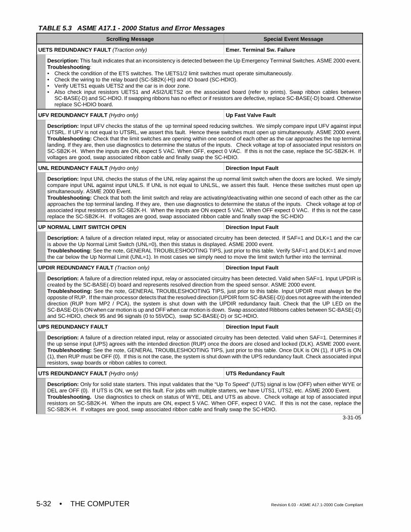
TABLE 5.3 ASME A17.1 - 2000 Status and Error Messages
Scrolling Message Special Event Message
• THE COMPUTER Revision 6.03 - ASME A17.1-2000 Code Compliant5-32
UETS REDUNDANCY FAULT (Traction only) Emer. Terminal Sw. Failure
Description: This fault indicates that an inconsistency is detected between the Up Emergency Terminal Switches. ASME 2000 event.Troubleshooting: • Check the condition of the ETS switches. The UETS1/2 limit switches must operate simultaneously.• Check the wiring to the relay board (SC-SB2K(-H)) and IO board (SC-HDIO).• Verify UETS1 equals UETS2 and the car is in door zone.• Also check input resistors UETS1 and ASI2/UETS2 on the associated board (refer to prints). Swap ribbon cables between
SC-BASE(-D) and SC-HDIO. If swapping ribbons has no effect or if resistors are defective, replace SC-BASE(-D) board. Otherwisereplace SC-HDIO board.
UFV REDUNDANCY FAULT (Hydro only) Up Fast Valve Fault
Description: Input UFV checks the status of the up terminal speed reducing switches. We simply compare input UFV against inputUTSRL. If UFV is not equal to UTSRL, we assert this fault. Hence these switches must open up simultaneously. ASME 2000 event.Troubleshooting: Check that the limit switches are opening within one second of each other as the car approaches the top terminallanding. If they are, then use diagnostics to determine the status of the inputs. Check voltage at top of associated input resistors onSC-SB2K-H. When the inputs are ON, expect 5 VAC. When OFF, expect 0 VAC. If this is not the case, replace the SC-SB2K-H. Ifvoltages are good, swap associated ribbon cable and finally swap the SC-HDIO.
UNL REDUNDANCY FAULT (Hydro only) Direction Input Fault
Description: Input UNL checks the status of the UNL relay against the up normal limit switch when the doors are locked. We simplycompare input UNL against input UNLS. If UNL is not equal to UNLSL, we assert this fault. Hence these switches must open upsimultaneously. ASME 2000 Event.Troubleshooting: Check that both the limit switch and relay are activating/deactivating within one second of each other as the carapproaches the top terminal landing. If they are, then use diagnostics to determine the status of the inputs. Check voltage at top ofassociated input resistors on SC-SB2K-H. When the inputs are ON expect 5 VAC. When OFF expect 0 VAC. If this is not the casereplace the SC-SB2K-H. If voltages are good, swap associated ribbon cable and finally swap the SC-HDIO
UP NORMAL LIMIT SWITCH OPEN Direction Input Fault
Description: A failure of a direction related input, relay or associated circuitry has been detected. If SAF=1 and DLK=1 and the caris above the Up Normal Limit Switch (UNL=0), then this status is displayed. ASME 2000 event.Troubleshooting: See the note, GENERAL TROUBLESHOOTING TIPS, just prior to this table. Verify SAF=1 and DLK=1 and movethe car below the Up Normal Limit (UNL=1). In most cases we simply need to move the limit switch further into the terminal.
UPDIR REDUNDANCY FAULT (Traction only) Direction Input Fault
Description: A failure of a direction related input, relay or associated circuitry has been detected. Valid when SAF=1. Input UPDIR iscreated by the SC-BASE(-D) board and represents resolved direction from the speed sensor. ASME 2000 event. Troubleshooting: See the note, GENERAL TROUBLESHOOTING TIPS, just prior to this table. Input UPDIR must always be theopposite of RUP. If the main processor detects that the resolved direction (UPDIR form SC-BASE(-D)) does not agree with the intendeddirection (RUP from MP2 / PCA), the system is shut down with the UPDIR redundancy fault. Check that the UP LED on theSC-BASE-D) is ON when car motion is up and OFF when car motion is down. Swap associated Ribbons cables between SC-BASE(-D)and SC-HDIO, check 95 and 96 signals (0 to 55VDC), swap SC-BASE(-D) or SC-HDIO.
UPS REDUNDANCY FAULT Direction Input Fault
Description: A failure of a direction related input, relay or associated circuitry has been detected. Valid when SAF=1. Determines ifthe up sense input (UPS) agrees with the intended direction (RUP) once the doors are closed and locked (DLK). ASME 2000 event.Troubleshooting: See the note, GENERAL TROUBLESHOOTING TIPS, just prior to this table. Once DLK is ON (1), if UPS is ON(1), then RUP must be OFF (0). If this is not the case, the system is shut down with the UPS redundancy fault. Check associated inputresistors, swap boards or ribbon cables to correct.
UTS REDUNDANCY FAULT (Hydro only) UTS Redundancy Fault
Description: Only for solid state starters. This input validates that the “Up To Speed” (UTS) signal is low (OFF) when either WYE orDEL are OFF (0). If UTS is ON, we set this fault. For jobs with multiple starters, we have UTS1, UTS2, etc. ASME 2000 Event. Troubleshooting. Use diagnostics to check on status of WYE, DEL and UTS as above. Check voltage at top of associated inputresistors on SC-SB2K-H. When the inputs are ON, expect 5 VAC. When OFF, expect 0 VAC. If this is not the case, replace theSC-SB2K-H. If voltages are good, swap associated ribbon cable and finally swap the SC-HDIO.
3-31-05
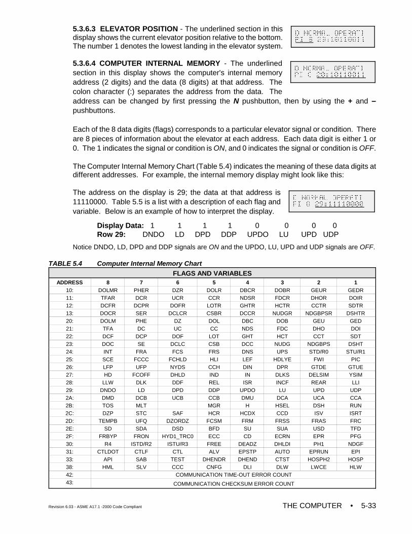
Revision 6.03 - ASME A17.1 -2000 Code Compliant THE COMPUTER • 5-33
5.3.6.3 ELEVATOR POSITION - The underlined section in thisdisplay shows the current elevator position relative to the bottom.The number 1 denotes the lowest landing in the elevator system.
5.3.6.4 COMPUTER INTERNAL MEMORY - The underlinedsection in this display shows the computer's internal memoryaddress (2 digits) and the data (8 digits) at that address. Thecolon character (:) separates the address from the data. Theaddress can be changed by first pressing the N pushbutton, then by using the + and –pushbuttons.
Each of the 8 data digits (flags) corresponds to a particular elevator signal or condition. Thereare 8 pieces of information about the elevator at each address. Each data digit is either 1 or0. The 1 indicates the signal or condition is ON, and 0 indicates the signal or condition is OFF.
The Computer Internal Memory Chart (Table 5.4) indicates the meaning of these data digits atdifferent addresses. For example, the internal memory display might look like this:
The address on the display is 29; the data at that address is11110000. Table 5.5 is a list with a description of each flag andvariable. Below is an example of how to interpret the display.
Display Data: 1 1 1 1 0 0 0 0Row 29: DNDO LD DPD DDP UPDO LU UPD UDP
Notice DNDO, LD, DPD and DDP signals are ON and the UPDO, LU, UPD and UDP signals are OFF.
TABLE 5.4 Computer Internal Memory ChartFLAGS AND VARIABLES
ADDRESS 8 7 6 5 4 3 2 110: DOLMR PHER DZR DOLR DBCR DOBR GEUR GEDR11: TFAR DCR UCR CCR NDSR FDCR DHOR DOIR12: DCFR DCPR DOFR LOTR GHTR HCTR CCTR SDTR13: DOCR SER DCLCR CSBR DCCR NUDGR NDGBPSR DSHTR20: DOLM PHE DZ DOL DBC DOB GEU GED21: TFA DC UC CC NDS FDC DHO DOI22: DCF DCP DOF LOT GHT HCT CCT SDT23: DOC SE DCLC CSB DCC NUDG NDGBPS DSHT24: INT FRA FCS FRS DNS UPS STD/R0 STU/R125: SCE FCCC FCHLD HLI LEF HDLYE FWI PIC26: LFP UFP NYDS CCH DIN DPR GTDE GTUE27: HD FCOFF DHLD IND IN DLKS DELSIM YSIM28: LLW DLK DDF REL ISR INCF REAR LLI29: DNDO LD DPD DDP UPDO LU UPD UDP2A: DMD DCB UCB CCB DMU DCA UCA CCA2B: TOS MLT MGR H HSEL DSH RUN2C: DZP STC SAF HCR HCDX CCD ISV ISRT2D: TEMPB UFQ DZORDZ FCSM FRM FRSS FRAS FRC2E: SD SDA DSD BFD SU SUA USD TFD2F: FRBYP FRON HYD1_TRC0 ECC CD ECRN EPR PFG30: R4 ISTD/R2 ISTU/R3 FREE DEADZ DHLDI PH1 NDGF31: CTLDOT CTLF CTL ALV EPSTP AUTO EPRUN EPI33: API SAB TEST DHENDR DHEND CTST HOSPH2 HOSP38: HML SLV CCC CNFG DLI DLW LWCE HLW42: COMMUNICATION TIME-OUT ERROR COUNT43: COMMUNICATION CHECKSUM ERROR COUNT
D NORMAL OPERATI
PI 8 20:10110011
D NORMAL OPERATI
PI 8 20:10110011
D NORMAL OPERATI
PI 8 29:11110000
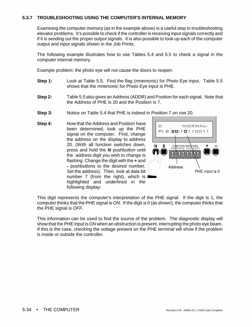
• THE COMPUTER Revision 6.03 - ASME A17.1-2000 Code Compliant5-34
5.3.7 TROUBLESHOOTING USING THE COMPUTER'S INTERNAL MEMORY
Examining the computer memory (as in the example above) is a useful step in troubleshootingelevator problems. It’s possible to check if the controller is receiving input signals correctly andif it is sending out the proper output signals. It is also possible to look up each of the computeroutput and input signals shown in the Job Prints.
The following example illustrates how to use Tables 5.4 and 5.5 to check a signal in thecomputer internal memory.
Example problem: the photo eye will not cause the doors to reopen.
Step 1: Look at Table 5.5. Find the flag (mnemonic) for Photo Eye input. Table 5.5shows that the mnemonic for Photo Eye input is PHE.
Step 2: Table 5.5 also gives an Address (ADDR) and Position for each signal. Note thatthe Address of PHE is 20 and the Position is 7.
Step 3: Notice on Table 5.4 that PHE is indeed in Position 7 on row 20.
Step 4: Now that the Address and Position havebeen determined, look up the PHEsignal on the computer. First, changethe address on the display to address20. (With all function switches down,press and hold the N pushbutton untilthe address digit you wish to change isflashing. Change the digit with the + and- pushbuttons to the desired number.Set the address). Then, look at data bitnumber 7 (from the right), which ishighlighted and underlined in thefollowing display:
This digit represents the computer's interpretation of the PHE signal. If the digit is 1, thecomputer thinks that the PHE signal is ON. If the digit is 0 (as shown), the computer thinks thatthe PHE signal is OFF.
This information can be used to find the source of the problem. The diagnostic display willshow that the PHE input is ON when an obstruction is present, interrupting the photo eye beam.If this is the case, checking the voltage present on the PHE terminal will show if the problemis inside or outside the controller.
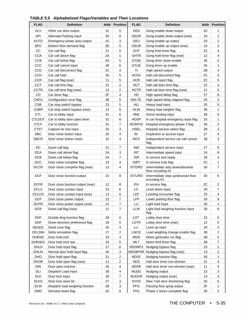
Revision 6.03 - ASME A17.1 -2000 Code Compliant THE COMPUTER • 5-35
TABLE 5.5 Alphabetized Flags/Variables and Their Locations
FLAG Definition Addr Position FLAG Definition Addr Position
ALV Other car alive output 31 5 GED Gong enable down output 20 1
API Alternate Parking Input 33 8 GEDR Gong enable down output (rear) 10 1
AUTO Emergency power auto output 31 3 GEU Gong enable up output 20 2
BFD Bottom floor demand flag 2E 5 GEUR Gong enable up output (rear) 10 2
CC Car call flag 21 5 GHT Gong hold timer flag 22 4
CCA Car call above flag 2A 1 GHTR Gong hold timer flag (rear) 12 4
CCB Car call below flag 2A 5 GTDE Gong timer down enable 26 2
CCC Car call cancel input 38 6 GTUE Gong timer up enable 26 1
CCD Car call disconnect flag 2C 3 H High speed output 2B 4
CCH Car call hold 26 5 HCDX Hall call disconnect flag 2C 4
CCR Car call flag (rear) 11 5 HCR Hall call reject flag 2C 5
CCT Car call time flag 22 2 HCT Hall call door time flag 22 3
CCTR Car call time flag (rear) 12 2 HCTR Hall call door time flag (rear) 12 3
CD Car done flag 2F 4 HD High speed delay flag 27 8
CNFG Configuration error flag 38 5 HDLYE High speed delay elapsed flag 25 3
CSB Car stop switch bypass 23 5 HLI Heavy load input 25 5
CSBR Car stop switch bypass (rear) 13 5 HLW Heavy load weigher flag 38 1
CTL Car to lobby input 31 6 HML Home landing input 38 8
CTLDOT Car to lobby door open timer 31 8 HOSP In car hospital emergency input flag 33 1
CTLF Car to lobby function 31 7 HOSPH2 Hospital emergency phase 2 flag 33 2
CTST Capture for test input 33 3 HSEL Hospital service select flag 2B 3
DBC Door close button input 20 4 IN Inspection or access input 27 4
DBCR Door close button (rear) 10 4 INCF Independent service car call cancelflag
28 3
DC Down call flag 21 7 IND Independent service input 27 5
DCA Down call above flag 2A 3 INT Intermediate speed input 24 8
DCB Down call below flag 2A 7 ISR In service and ready 28 4
DCC Door close complete flag 23 4 ISRT In service truly flag 2C 1
DCCR Door close complete flag (rear) 13 4 ISTD/R2 Intermediate step down/absolutefloor encoding #2
30 7
DCF Door close function output 22 8 ISTU/R3 Intermediate step up/absolute floorencoding #3
30 6
DCFR Door close function output (rear) 12 8 ISV In service flag 2C 2
DCLC Door close contact input 23 6 LD Level down input 29 7
DCLCR Door close contact input (rear) 13 6 LEF Leveling encounter flag 25 4
DCP Door close power output 22 7 LFP Lower parking floor flag 26 8
DCPR Door close power output (rear) 12 7 LLI Light load input 28 1
DCR Down call flag (rear) 11 7 LLW Light load weighing function inputflag
28 8
DDF Double ding function flag 28 6 LOT Lobby door time 22 5
DDP Down direction preference flag 29 5 LOTR Lobby door time (rear) 12 5
DEADZ Dead zone flag 30 4 LU Level up input 29 3
DELSIM Delta simulation flag 27 2 LWCE Load weighing change enable flag 38 2
DHEND Door hold end 33 4 MGR Motor generator run flag 2B 5
DHEND2 Door hold end rear 33 5 MLT Motor limit timer flag 2B 7
DHLD Door hold input flag 27 6 NDGBPS Nudging bypass flag 23 2
DHLDI Normal door hold input flag 30 3 NDGBPSR Nudging bypass flag (rear) 13 2
DHO Door hold open flag 21 2 NDGF Nudging function flag 30 1
DHOR Door hold open flag (rear) 11 2 NDS Hall door timer non-shorten 21 4
DIN Door open inactive 26 4 NDSR Hall door timer non-shorten (rear) 11 4
DLI Dispatch Load Input 38 4 NUDG Nudging output 23 3
DLK Door lock input 28 7 NUDGR Nudging output (rear) 13 3
DLKS Door lock store bit 27 3 NYDS New York door shortening flag 26 6
DLW Dispatch load weighing function 38 3 PFG Passing floor gong output 2F 1
DMD Demand down flag 2A 8 PH1 Phase 1 return complete flag 30 2
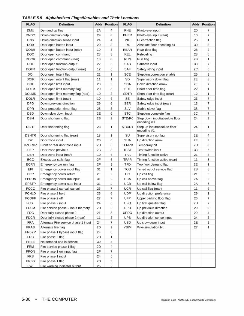
TABLE 5.5 Alphabetized Flags/Variables and Their Locations
FLAG Definition Addr Position FLAG Definition Addr Position
• THE COMPUTER Revision 6.03 - ASME A17.1-2000 Code Compliant5-36
DMU Demand up flag 2A 4 PHE Photo eye input 20 7
DNDO Down direction output 29 8 PHER Photo eye input (rear) 10 7
DNS Down direction sense input 24 4 PIC PI correction flag 25 1
DOB Door open button input 20 3 R4 Absolute floor encoding #4 30 8
DOBR Door open button input (rear) 10 3 REAR Rear door flag 28 2DOC Door open command 23 8 REL Releveling 28 5
DOCR Door open command (rear) 13 8 RUN Run flag 2B 1
DOF Door open function output 22 6 SAB Sabbath input 33 7
DOFR Door open function output (rear) 12 6 SAF Safety string input 2C 6
DOI Door open intent flag 21 1 SCE Stepping correction enable 25 8
DOIR Door open intent flag (rear) 11 1 SD Supervisory down flag 2E 8
DOL Door open limit input 20 5 SDA Down direction arrow 2E 7
DOLM Door open limit memory flag 20 8 SDT Short door time flag 22 1
DOLMR Door open limit memory flag (rear) 10 8 SDTR Short door time flag (rear) 12 1
DOLR Door open limit (rear) 10 5 SE Safety edge input 23 7
DPD Down previous direction 29 6 SER Safety edge input (rear) 13 7
DPR Door protection timer flag 26 3 SLV Stable slave flag 38 7
DSD Down slow down input 2E 6 STC Stepping complete flag 2C 7
DSH Door shortening flag 2B 2 STD/R0 Step down input/absolute floorencoding #0
24 2
DSHT Door shortening flag 23 1 STU/R1 Step up input/absolute floorencoding #1
24 1
DSHTR Door shortening flag (rear) 13 1 SU Supervisory up flag 2E 4
DZ Door zone input 20 6 SUA Up direction arrow 2E 3
DZORDZ Front or rear door zone input 2D 6 TEMPB Temporary bit 2D 8
DZP Door zone previous 2C 8 TEST Test switch input 33 6
DZR Door zone input (rear) 10 6 TFA Timing function active 21 8
ECC Excess car calls flag 2F 5 TFAR Timing function active (rear) 11 8
ECRN Emergency car run flag 2F 3 TFD Top floor demand flag 2E 1
EPI Emergency power input flag 31 1 TOS Timed out of service flag 2B 8
EPR Emergency power return 2F 2 UC Up call flag 21 6
EPRUN Emergency power run input 31 2 UCA Up call above flag 2A 2
EPSTP Emergency power stop input 31 4 UCB Up call below flag 2A 6
FCCC Fire phase 2 car call cancel 25 7 UCR Up call flag (rear) 11 6
FCHLD Fire phase 2 hold 25 6 UDP Up direction preference 29 1
FCOFF Fire phase 2 off 27 7 UFP Upper parking floor flag 26 7
FCS Fire phase 2 input 24 6 UFQ Up first qualifier flag 2D 7
FCSM Fire service phase 2 input memory 2D 5 UPD Up previous direction 29 2
FDC Door fully closed phase 2 21 3 UPDO Up direction output 29 4
FDCR Door fully closed phase 2 (rear) 11 3 UPS Up direction sense input 24 3
FRA Alternate Fire service phase 1 input 24 7 USD Up slow down input 2E 2
FRAS Alternate fire flag 2D 2 YSIM Wye simulation bit 27 1
FRBYP Fire phase 1 bypass input flag 2F 8
FRC Fire phase 2 flag 2D 1
FREE No demand and in service 30 5
FRM Fire service phase 1 flag 2D 4
FRON Fire phase 1 on input flag 2F 7
FRS Fire phase 1 input 24 5
FRSS Fire phase 1 flag 2D 3
FWI Fire warning indicator output 25 2
Revision 6.03 - ASME A17.1 -2000 Code Compliant THE COMPUTER • 5-37
NOTE: If the controller has the Absolute Floor Encoding feature, then the controllercan establish the position of the car as soon as the car reaches any doorzone. The car does not have to travel to a terminal landing to establish theposition of the car.
5.3.8 TROUBLESHOOTING SPECIFIC PROBLEMS
This section will describe how to solve some specific problems by using the computer panel.
5.3.8.1 PROBLEM: THE BFD/TFD ERROR MESSAGE IS FLASHING ON THE DISPLAY -As shown in Table 5.2, the message means that there is either a Bottom Floor Demand or aTop Floor Demand. The controller is trying to establish the position of the car by sending it toeither the bottom or top floor.
It is normal for the BFD/TFD message to appear on the display right after power up or after thecar is taken off Inspection or after the COMPUTER RESET button is pressed. However, in allthree cases, the BFD/TFD message should clear quickly and then should not appear again asthe car runs on Normal service.
If the BFD/TFD message is flashing for no apparent reason, take the following steps:
The first step in troubleshooting is to decide which of the following scenarios applies:
Scenario A: The car is stuck at the bottom floor with the BFD/TFD error message flashingconstantly.
-OR-
Scenario B: The car runs normally until it reaches the top floor, then the BFD/TFD errormessage flashes and the car goes to the bottom floor. When it reaches thebottom, the message is cleared and the car functions normally until it againreaches the top floor.
-OR-
Scenario C: The car runs normally until it reaches the bottom floor. Then the BFD/TFDerror message flashes and the car goes to the top. After it gets there, themessage is cleared and the car runs normally until it again reaches the bottomfloor.
WHAT TO DO FOR SCENARIO A: A Bottom Floor Demand should clear when all of thefollowing conditions are met:
1. The car is at the bottom and the Down Slow Down (DSD) input to the controller is OFF.2. The Door Zone (DZ) input to the controller is ON.3. The Door Lock (DLK) input to the controller is ON.
Look up the DSD, DZ and DLK signals in the computer memory (see Section 5.3.7 for anexplanation). When the car is at the bottom floor with the doors locked, the correct values forthese signals in the computer memory are as follows:
DSD = 0 (OFF)DZ = 1 (ON)DLK = 1 (ON)
• THE COMPUTER Revision 6.03 - ASME A17.1-2000 Code Compliant5-38
If there is a different value for any of the 3 signals, check the wiring associated with thatparticular signal. For example, if the DSD signal is equal to 1 (ON) in the computer memory,inspect the DSD input wiring, including the Down Slow Down limit switch. The Down Slow Downswitch contacts should be open when the car is at the bottom.
WHAT TO DO FOR SCENARIO B: For scenario B, the USD input is usually the problem. Lookat the USD signal in the computer memory (Address 2E, Position 2). USD should be ONexcept when the car is at the top; then it should be OFF. If the signal is not following this rule,then inspect the wiring associated with the USD input, including the Up Slow Down limit switch.The Up Slow Down switch contacts should be open when the car is at the top.
WHAT TO DO FOR SCENARIO C: For scenario C, the DSD input is usually the problem. Lookat the DSD signal in the computer memory (Address 2E, Position 6). DSD should be ONexcept when the car is at the bottom; then it should be OFF. If the signal is not following thisrule, then inspect the wiring associated with the DSD input, including the Down Slow Down limitswitch. The Down Slow Down switch contacts should be open when the car is at the bottom.
5.3.8.2 PROBLEMS WITH CALLS - See Section 6.3, for Call Logic and Troubleshooting ofcall circuits.
5.3.8.3 PROBLEMS WITH DOORS - See Sections 6.2 and 5.3.7, which explain how to usecomputer memory to solve door problems.
5.3.9 SETTING PARAMETERS (OPTIONS) TO DEFAULT VALUES
There are occasions when it is necessary to set the parameters (options) to their default values.Setting the parameters to their default values is usually required when:
• The MC-PCA and/or MC-PA software is changed (EPROMS changed), e.g. MC-PCAsoftware changed from version 5.02.xxxx to version 5.03.xxxx.
• RAM memory becomes corrupted. This sometimes happens due to lightening.
• Changes to Communication Port settings on the MC-PCA require that the MC-PAparameters be set to their default values.
To set the MC-PCA parameters to their default values:
1. Place the car on Machine Room Inspection.
2. Place function switches F1, F3, F5 and F7 in the On (up) position.
3. Press all four pushbuttons (N, S, +, -) at the same time.
4. Using the settings shown in Appendix A, Original Programmed Values and the Recordof Changes, reprogram the values that are different from the default values.
To set the MC-PA parameters to their default values:
1. Place function switches A1, A3, A5 and A7 in the On (up) position.
2. Press the Reset button on the MC-PA board.
3. Keep function switches A1, A3, A5 and A7 in the On (up) position for about 30 secondsor until the CRT terminal reinitializes.
4. If you have a CRT terminal, verify that parameters are correct (security and/or CMSparameters must be reprogrammed).
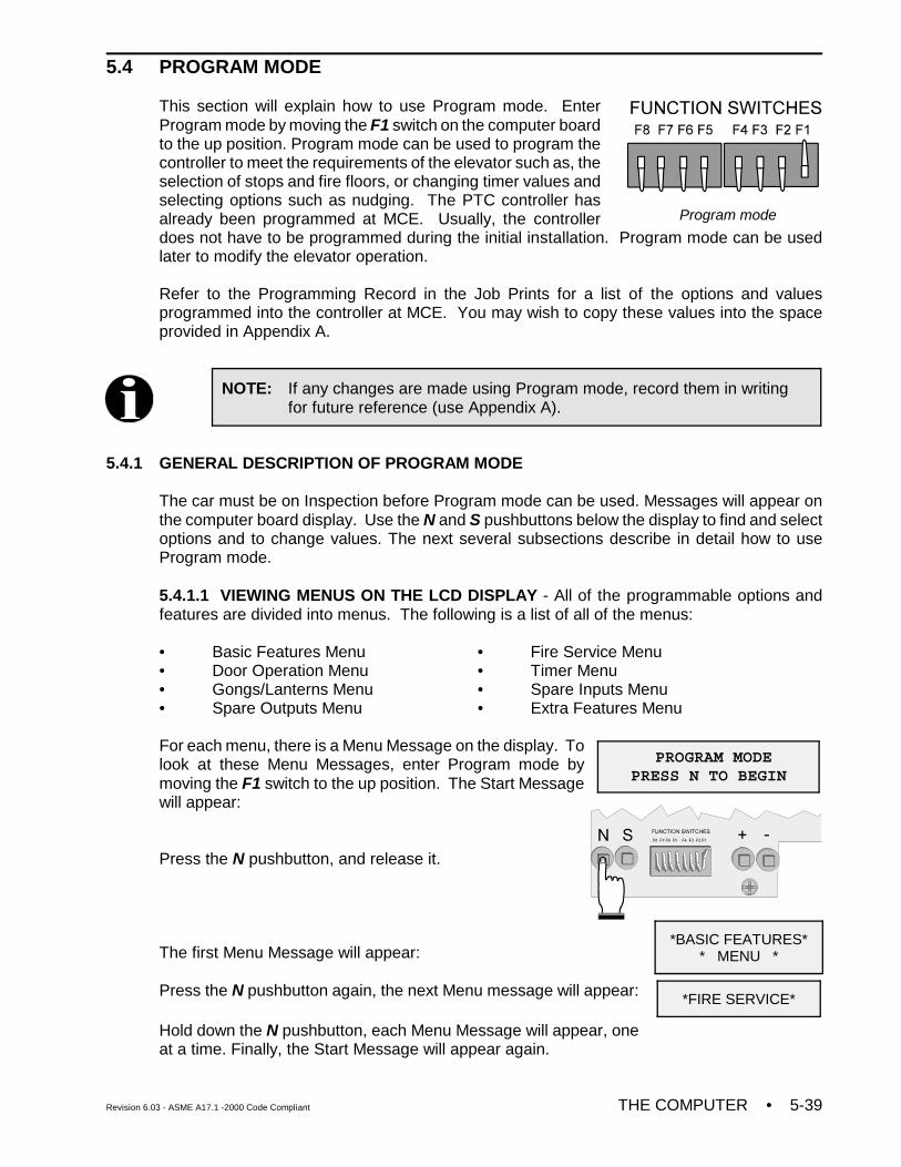
Revision 6.03 - ASME A17.1 -2000 Code Compliant THE COMPUTER • 5-39
Program mode
NOTE: If any changes are made using Program mode, record them in writingfor future reference (use Appendix A).
PROGRAM MODE PRESS N TO BEGIN
5.4 PROGRAM MODE
This section will explain how to use Program mode. EnterProgram mode by moving the F1 switch on the computer boardto the up position. Program mode can be used to program thecontroller to meet the requirements of the elevator such as, theselection of stops and fire floors, or changing timer values andselecting options such as nudging. The PTC controller hasalready been programmed at MCE. Usually, the controllerdoes not have to be programmed during the initial installation. Program mode can be usedlater to modify the elevator operation.
Refer to the Programming Record in the Job Prints for a list of the options and valuesprogrammed into the controller at MCE. You may wish to copy these values into the spaceprovided in Appendix A.
5.4.1 GENERAL DESCRIPTION OF PROGRAM MODE
The car must be on Inspection before Program mode can be used. Messages will appear onthe computer board display. Use the N and S pushbuttons below the display to find and selectoptions and to change values. The next several subsections describe in detail how to useProgram mode.
5.4.1.1 VIEWING MENUS ON THE LCD DISPLAY - All of the programmable options andfeatures are divided into menus. The following is a list of all of the menus:
• Basic Features Menu • Fire Service Menu• Door Operation Menu • Timer Menu• Gongs/Lanterns Menu • Spare Inputs Menu• Spare Outputs Menu • Extra Features Menu
For each menu, there is a Menu Message on the display. Tolook at these Menu Messages, enter Program mode bymoving the F1 switch to the up position. The Start Messagewill appear:
Press the N pushbutton, and release it.
The first Menu Message will appear:
Press the N pushbutton again, the next Menu message will appear:
Hold down the N pushbutton, each Menu Message will appear, oneat a time. Finally, the Start Message will appear again.
*BASIC FEATURES** MENU *
*FIRE SERVICE*
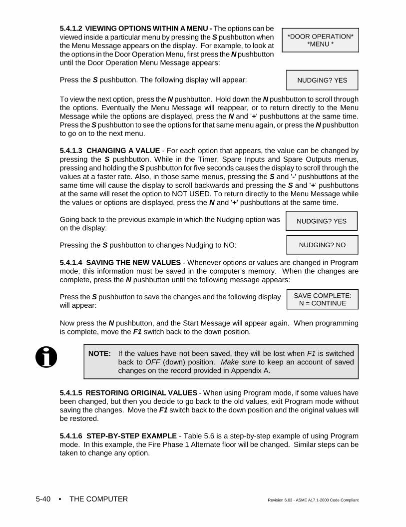
• THE COMPUTER Revision 6.03 - ASME A17.1-2000 Code Compliant5-40
NOTE: If the values have not been saved, they will be lost when F1 is switchedback to OFF (down) position. Make sure to keep an account of savedchanges on the record provided in Appendix A.
5.4.1.2 VIEWING OPTIONS WITHIN A MENU - The options can beviewed inside a particular menu by pressing the S pushbutton whenthe Menu Message appears on the display. For example, to look atthe options in the Door Operation Menu, first press the N pushbuttonuntil the Door Operation Menu Message appears:
Press the S pushbutton. The following display will appear:
To view the next option, press the N pushbutton. Hold down the N pushbutton to scroll throughthe options. Eventually the Menu Message will reappear, or to return directly to the MenuMessage while the options are displayed, press the N and '+' pushbuttons at the same time.Press the S pushbutton to see the options for that same menu again, or press the N pushbuttonto go on to the next menu.
5.4.1.3 CHANGING A VALUE - For each option that appears, the value can be changed bypressing the S pushbutton. While in the Timer, Spare Inputs and Spare Outputs menus,pressing and holding the S pushbutton for five seconds causes the display to scroll through thevalues at a faster rate. Also, in those same menus, pressing the S and '-' pushbuttons at thesame time will cause the display to scroll backwards and pressing the S and '+' pushbuttonsat the same will reset the option to NOT USED. To return directly to the Menu Message whilethe values or options are displayed, press the N and '+' pushbuttons at the same time.
Going back to the previous example in which the Nudging option wason the display:
Pressing the S pushbutton to changes Nudging to NO:
5.4.1.4 SAVING THE NEW VALUES - Whenever options or values are changed in Programmode, this information must be saved in the computer's memory. When the changes arecomplete, press the N pushbutton until the following message appears:
Press the S pushbutton to save the changes and the following displaywill appear:
Now press the N pushbutton, and the Start Message will appear again. When programmingis complete, move the F1 switch back to the down position.
5.4.1.5 RESTORING ORIGINAL VALUES - When using Program mode, if some values havebeen changed, but then you decide to go back to the old values, exit Program mode withoutsaving the changes. Move the F1 switch back to the down position and the original values willbe restored.
5.4.1.6 STEP-BY-STEP EXAMPLE - Table 5.6 is a step-by-step example of using Programmode. In this example, the Fire Phase 1 Alternate floor will be changed. Similar steps can betaken to change any option.
*DOOR OPERATION**MENU *
NUDGING? YES
NUDGING? YES
NUDGING? NO
SAVE COMPLETE:N = CONTINUE
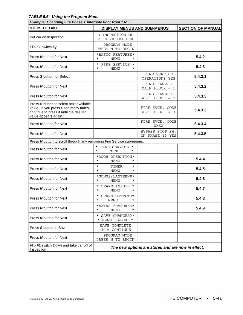
Revision 6.03 - ASME A17.1 -2000 Code Compliant THE COMPUTER • 5-41
TABLE 5.6 Using the Program ModeExample: Changing Fire Phase 1 Alternate floor from 1 to 3
STEPS TO TAKE DISPLAY MENUS AND SUB-MENUS SECTION OF MANUAL
Put car on InspectionD INSPECTION OPPI 8 20:1011000
Flip F1 switch Up PROGRAM MODE
PRESS N TO BEGIN
Press N button for Next*BASIC FEATURES** MENU * 5.4.2
Press N button for Next* FIRE SERVICE ** MENU * 5.4.3
Press S button for SelectFIRE SERVICE
OPERATION? YES 5.4.3.1
Press N button for NextFIRE PHASE 1
MAIN FLOOR = 1 5.4.3.2
Press N button for NextFIRE PHASE 1
ALT. FLOOR = 2 5.4.3.3
Press S button to select next availablevalue. If you press S too many times,continue to press it until the desiredvalue appears again.
FIRE SVCE. CODEALT. FLOOR = 3 5.4.3.3
Press N button for NextFIRE SVCE. CODE
XXXX 5.4.3.4
Press N button for NextBYPASS STOP SW.ON PHASE 1? YES 5.4.3.5
Press N button to scroll through any remaining Fire Service sub-menus.
Press N button for Next* FIRE SERVICE ** MENU *
Press N button for Next*DOOR OPERATION** MENU * 5.4.4
Press N button for Next* TIMER ** MENU * 5.4.5
Press N button for Next*GONGS/LANTERNS** MENU * 5.4.6
Press N button for Next* SPARE INPUTS ** MENU * 5.4.7
Press N button for Next* SPARE OUTPUTS** MENU * 5.4.8
Press N button for Next*EXTRA FEATURES** MENU * 5.4.9
Press N button for Next* SAVE CHANGES?** N=NO S=YES *
Press S button to Save SAVE COMPLETE: N = CONTINUE
Press N button for Next PROGRAM MODE
PRESS N TO BEGIN
Flip F1 switch Down and take car off ofInspection The new options are stored and are now in effect.
• THE COMPUTER Revision 6.03 - ASME A17.1-2000 Code Compliant5-42
NOTE: If either Single Button Collective or Single Automatic Push-Button operationis selected, then one of the spare output terminals should be used for anINDFRC output. This output is used to cut out the hall calls during FireService and Independent Service (see Section 5.4.8 for more details).Refer to the Job Prints for information on using the INDFRC output to cutout hall calls.
5.4.2 BASIC FEATURE MENU OPTIONS
5.4.2.1 SIMPLEX OR DUPLEX? - The controller has been programmed at the factory foreither simplex or duplex capability.
If the controller has simplex capability, it can only operate a single car as a simplex. TheSimplex/Duplex option message will not appear on the display.
If the controller has duplex capability, then it can operate a single car as a simplex, or it can beconnected to a second PTC controller and the 2 controllers can operate 2 cars as a duplex.
Both PTC controllers must have duplex capability for this arrangement to work. Also, theSimplex/Duplex option on each controller must be set to duplex.
5.4.2.2 OPERATION (DISPATCHING OPERATION) - For simplex operation, there are 3dispatching operations to choose from: Selective Collective, Single Button Collective, or SingleAutomatic Pushbutton. Each operation is described below.
Selective Collective - Choose this operation if there is an UP and DOWN button at eachlanding station except for the top floor (DOWN button only) and bottom floor (UP buttononly) and any number of calls can be registered at one time.
Single Button Collective - Choose this operation if there is only 1 call button at eachlanding station and any number of calls can be registered at one time.
Single Automatic Pushbutton - Choose this operation if there is only 1 call button ateach landing station and only 1 call can be registered and/or serviced at a time.
For duplex operation, the dispatching scheme is always Selective Collective. Therefore, theOperation option message will not appear on the display if the Duplex option was selected.
5.4.2.3 TOP LANDING SERVED? (simplex) / TOP LANDING FOR THIS CAR? (duplex) -Set this option to the highest floor served by this car.
5.4.2.4 CAR DOORS ARE WALK-THRU? (simplex) / THIS CARS DOORS WALK-THRU?(duplex) - Set this option to YES if independent (walk-through) doors are served by this car.
5.4.2.5 CAR SERVES FRNT/FLR 1? (simplex) /THIS CAR SERVES FRNT/FLR 1? (duplex) -Setting this option to YES indicates that this car is eligible to serve a front opening at this floor.This option will continue to be asked until the top landing is reached. Press the '+' pushbuttonto scroll through the available landings. Press the N pushbutton for the next option.
5.4.2.6 CAR SERVES REAR/FLR 1? (simplex) / THIS CAR SERVES REAR/FLR 1?(duplex) - Setting this option to YES indicates that this car is eligible to serve a rear openingat this floor. This option will not be displayed if option 5.4.2.4 is set to NO. This option inquirywill continue until the top landing is reached. Press the '+' pushbutton to scroll through theavailable landings. Press the N pushbutton for the next option.
Revision 6.03 - ASME A17.1 -2000 Code Compliant THE COMPUTER • 5-43
For a duplex, option inquiries for 5.4.2.3 through 5.4.2.6 must be answered for both cars. Eachmessage will ask what the other car’s top landing is, if it serves rear floors, etc. Again, selectYES if the other car of the duplex serves that floor and NO if the other car does not. Bothcontrollers in a duplex need to be programmed with this information.
5.4.2.7 PARKING FLOOR - Any landing can be selected to be the parking floor. The car willgo to the parking floor when it is free of call demand. In addition, there is a Parking DelayTimer that will cause a free car to wait for a short time before parking. The timer is adjustable,with a value between 0.0 minutes (no delay) and 6.0 minutes (see Section 5.4.5.10 for moredetails). If the parking feature is not needed, choose NONE when the Parking Floor optionmessage is on the display. The car will stay at the last call answered.
5.4.2.8 ALT. PARKING FLOOR - This option is available only when the API input isprogrammed and a parking floor is set. Any landing can be selected to be the alternate parkingfloor. This car will go to the alternate parking floor when it is free of call demand and the APIinput is active.
5.4.2.9 SECONDARY PARKING FLOOR - This option is for duplex systems only. Any landingcan be selected to be the secondary parking floor. The car will go to this floor when it becomesfree of call demand and the other car is already parked at the first parking floor. It is acceptableto make the secondary parking floor the same as the first parking floor, if both cars are to parkat the same floor. If a second parking floor is not needed, choose NONE when the SecondaryPark Floor option message is on the display. Then, the first free car will go to the first parkingfloor, but the second car will stay at the last call answered.
5.4.2.10 LOBBY FLOOR - Any landing can be selected to be the Lobby Floor. When the caranswers either a hall or car call at this floor, the doors will stay open until the Lobby Door Timerelapses (the Lobby Door Timer is adjustable, see Section 5.4.5.4). NOTE: The Lobby Flooris also used for CTL input.
5.4.2.11 CAR IDENTIFIER - This option is for duplex systems only. Its purpose is to specifywhich controller is assigned to car A and which controller is assigned to car B. This is primarilyused for controllers that use a peripheral device such as a CRT.
5.4.2.12 NUMBER OF IOX BOARDS? - Program the number of HC-IOX boards installed inthe controller (valid range is 0 to 4).
5.4.2.13 NUMBER OF I4O BOARDS? - Program the number of HC-I4O boards installed inthe controller (valid range is 0 to 3).
5.4.2.14 NUMBER OF AIOX BOARDS? - Program the number of HC-AIOX boards installedin the controller (valid range is 0 or 1).
5.4.3 FIRE SERVICE MENU OPTIONS
5.4.3.1 FIRE SERVICE OPERATION? - If Fire Service operation is not required, then thisoption should be set to NO. Otherwise, if set to YES, the options below will appear on the LCDdisplay.
5.4.3.2 FIRE PHASE 1 MAIN FLOOR - Any landing can be selected to be the Main Fire ReturnFloor for Fire Service.
5.4.3.3 FIRE PHASE 1 ALT. FLOOR - Any landing can be selected to be the Alternate FireReturn Floor for Fire Service.
• THE COMPUTER Revision 6.03 - ASME A17.1-2000 Code Compliant5-44
5.4.3.4 FIRE SVCE. CODE - The Fire Service Operation will conform to the selected fireservice code. There are fourteen different codes to choose from:
1. CHICAGO (OLD) 9. CITY OF HOUSTON2. VET ADMIN (Veterans' Administration) 10. AUSTRALIA3. NYC RS-18 11. CITY OF DETROIT4. ANSI A17.1 -89> 12. MASSACHUSETTS5. CALIF. TITLE 8 13. ANSI A17.1 85 - 886. HAWAII 14. CITY OF DENVER7. CSA B44-M90 15. CHICAGO 20018. 34 PA CODE, CH. 7 16. A17.1 - 2000
5.4.3.5 FIRE PHASE I 2ND ALT. FLOOR - This option is only available when the FIR SVCECODE option is set to City of Detroit. Any landing can be selected to be the 2nd alternate firereturn floor.
5.4.3.6 BYPASS STOP SW. ON PHASE 1? - This option was added to keep the stop switchfrom being bypassed on Fire Phase I. With this option set to NO, the CSB output will not comeon as the car is returning on Fire Phase I.
5.4.3.7 HONEYWELL FIRE OPERATION? (YES/NO) - This option is only available if the FIRESVCE. CODE option is set to AUSTRALIA (see section 5.4.3.4). If this option is set to YESthen the Australia fire code will conform to Honeywell’s requirements. If this option is set to NOthen the controller will conform to standard Australia code.
5.4.3.8 NEW YORK CITY FIRE PHASE 2 AND ANSI 89? (YES/NO) - This option is onlyavailable if the FIRE SVCE. CODE option is set to ANSI A17.1 89 (see section 5.4.3.4). If thisoption is set to YES then the ANSI A17.1 89 Fire Code will conform to New York City Fire Coderequirements when on Fire Phase 2. If this option is set to NO then the controller will conformto standard ANSI A17.1 89 Fire Code.
5.4.3.9 WHITE PLAINS, NY FIRE CODE? (YES/NO) - This option is only available if the FIRESVCE. CODE option is set to ANSI A17.1 89 (see section 5.4.3.4). The city of White Plainsrequires that if fire phase one is still in effect, the car can exit fire phase two regardless of theposition of the doors. Setting this option to YES will comply with this requirement.
5.4.3.10 MASS 524 CMR FIRE CODE? (YES/NO) - This option is only available if the “FIRESVCE. CODE” option is set to “A17.1 - 2000". If this option is set to YES, the ASME A17.1-2000 fire code will conform to the Massachusetts 524 CMR requirements. If this option is setto NO, the controller will conform to the standard ASME A17.1-2000 code.
5.4.4 DOOR OPERATION MENU OPTIONS
5.4.4.1 NUDGING? - This option causes Nudging Operation to occur when the doors areprevented from closing. During Nudging Operation, the controller will turn ON the NUDGoutput, to signal the door operator to close the doors at a reduced speed. The NUDG outputwill stay ON for the amount of time the Nudging Timer is set, and then cycle OFF for the sameamount of time. This cycle will continue until the doors have become fully closed. The NUDGoutput can also be used to activate a buzzer. The PHE (Photo Eye) input will be ignored duringnudging, if the Stuck Photo Eye Protection option has been selected (see Section 5.4.4.2). ASafety Edge or Door Open Button input will stop the doors from closing, but will not reopen thedoors fully. Nudging Operation will begin when the Nudging Timer elapses. The NudgingTimer starts when the regular door timer elapses. The Nudging Timer is adjustable, with avalue between 10 and 60 seconds (see Section 5.4.5.5).
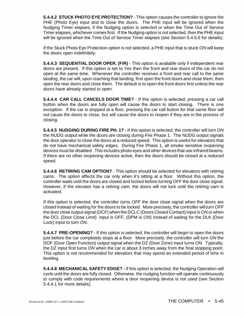
Revision 6.03 - ASME A17.1 -2000 Code Compliant THE COMPUTER • 5-45
5.4.4.2 STUCK PHOTO EYE PROTECTION? - This option causes the controller to ignore thePHE (Photo Eye) input and to close the doors. The PHE input will be ignored when theNudging Timer elapses, if the Nudging option is selected or when the Time Out of ServiceTimer elapses, whichever comes first. If the Nudging option is not selected, then the PHE inputwill be ignored when the Time Out of Service Timer elapses (see Section 5.4.5.6 for details).
If the Stuck Photo Eye Protection option is not selected, a PHE input that is stuck ON will keepthe doors open indefinitely.
5.4.4.3 SEQUENTIAL DOOR OPER. (F/R) - This option is available only if independent reardoors are present. If this option is set to Yes then the front and rear doors of the car do notopen at the same time. Whenever the controller receives a front and rear call to the samelanding, the car will, upon reaching that landing, first open the front doors and close them, thenopen the rear doors and close them. The default is to open the front doors first unless the reardoors have already started to open.
5.4.4.4 CAR CALL CANCELS DOOR TIME? - If this option is selected, pressing a car callbutton when the doors are fully open will cause the doors to start closing. There is oneexception. If the car is stopped at a floor, pressing the car call button for that same floor willnot cause the doors to close, but will cause the doors to reopen if they are in the process ofclosing.
5.4.4.5 NUDGING DURING FIRE PH. 1? - If this option is selected, the controller will turn ONthe NUDG output while the doors are closing during Fire Phase 1. The NUDG output signalsthe door operator to close the doors at a reduced speed. This option is useful for elevators thatdo not have mechanical safety edges. During Fire Phase 1, all smoke sensitive reopeningdevices must be disabled. This includes photo eyes and other devices that use infrared beams.If there are no other reopening devices active, then the doors should be closed at a reducedspeed.
5.4.4.6 RETIRING CAM OPTION? - This option should be selected for elevators with retiringcams. The option affects the car only when it’s sitting at a floor. Without this option, thecontroller waits until the doors are closed and locked before turning OFF the door close signal.However, if the elevator has a retiring cam, the doors will not lock until the retiring cam isactivated.
If this option is selected, the controller turns OFF the door close signal when the doors areclosed instead of waiting for the doors to be locked. More precisely, the controller will turn OFFthe door close output signal (DCF) when the DCLC (Doors Closed Contact) input is ON or whenthe DCL (Door Close Limit) input is OFF, (DPM is ON) instead of waiting for the DLK (DoorLock) input to turn ON.
5.4.4.7 PRE-OPENING? - If this option is selected, the controller will begin to open the doorsjust before the car completely stops at a floor. More precisely, the controller will turn ON theDOF (Door Open Function) output signal when the DZ (Door Zone) input turns ON. Typically,the DZ input first turns ON when the car is about 3 inches away from the final stopping point.This option is not recommended for elevators that may spend an extended period of time inleveling.
5.4.4.8 MECHANICAL SAFETY EDGE? - If this option is selected, the Nudging Operation willcycle until the doors are fully closed. Otherwise, the nudging function will operate continuouslyto comply with code requirements where a door reopening device is not used (see Section5.4.4.1 for more details).
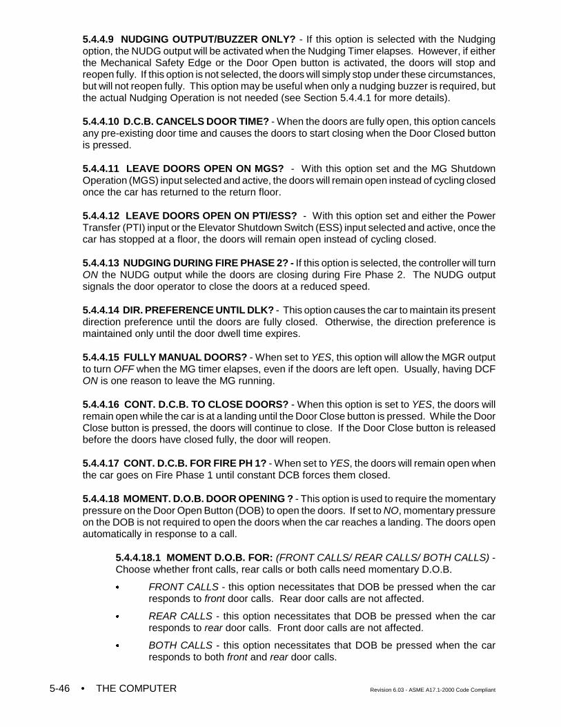
• THE COMPUTER Revision 6.03 - ASME A17.1-2000 Code Compliant5-46
5.4.4.9 NUDGING OUTPUT/BUZZER ONLY? - If this option is selected with the Nudgingoption, the NUDG output will be activated when the Nudging Timer elapses. However, if eitherthe Mechanical Safety Edge or the Door Open button is activated, the doors will stop andreopen fully. If this option is not selected, the doors will simply stop under these circumstances,but will not reopen fully. This option may be useful when only a nudging buzzer is required, butthe actual Nudging Operation is not needed (see Section 5.4.4.1 for more details).
5.4.4.10 D.C.B. CANCELS DOOR TIME? - When the doors are fully open, this option cancelsany pre-existing door time and causes the doors to start closing when the Door Closed buttonis pressed.
5.4.4.11 LEAVE DOORS OPEN ON MGS? - With this option set and the MG ShutdownOperation (MGS) input selected and active, the doors will remain open instead of cycling closedonce the car has returned to the return floor.
5.4.4.12 LEAVE DOORS OPEN ON PTI/ESS? - With this option set and either the PowerTransfer (PTI) input or the Elevator Shutdown Switch (ESS) input selected and active, once thecar has stopped at a floor, the doors will remain open instead of cycling closed.
5.4.4.13 NUDGING DURING FIRE PHASE 2? - If this option is selected, the controller will turnON the NUDG output while the doors are closing during Fire Phase 2. The NUDG outputsignals the door operator to close the doors at a reduced speed.
5.4.4.14 DIR. PREFERENCE UNTIL DLK? - This option causes the car to maintain its presentdirection preference until the doors are fully closed. Otherwise, the direction preference ismaintained only until the door dwell time expires.
5.4.4.15 FULLY MANUAL DOORS? - When set to YES, this option will allow the MGR outputto turn OFF when the MG timer elapses, even if the doors are left open. Usually, having DCFON is one reason to leave the MG running.
5.4.4.16 CONT. D.C.B. TO CLOSE DOORS? - When this option is set to YES, the doors willremain open while the car is at a landing until the Door Close button is pressed. While the DoorClose button is pressed, the doors will continue to close. If the Door Close button is releasedbefore the doors have closed fully, the door will reopen.
5.4.4.17 CONT. D.C.B. FOR FIRE PH 1? - When set to YES, the doors will remain open whenthe car goes on Fire Phase 1 until constant DCB forces them closed.
5.4.4.18 MOMENT. D.O.B. DOOR OPENING ? - This option is used to require the momentarypressure on the Door Open Button (DOB) to open the doors. If set to NO, momentary pressureon the DOB is not required to open the doors when the car reaches a landing. The doors openautomatically in response to a call.
5.4.4.18.1 MOMENT D.O.B. FOR: (FRONT CALLS/ REAR CALLS/ BOTH CALLS) -Choose whether front calls, rear calls or both calls need momentary D.O.B.
C FRONT CALLS - this option necessitates that DOB be pressed when the carresponds to front door calls. Rear door calls are not affected.
C REAR CALLS - this option necessitates that DOB be pressed when the carresponds to rear door calls. Front door calls are not affected.
C BOTH CALLS - this option necessitates that DOB be pressed when the carresponds to both front and rear door calls.
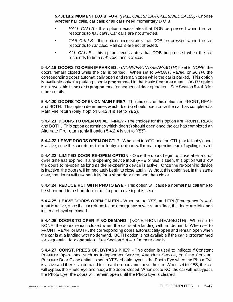
Revision 6.03 - ASME A17.1 -2000 Code Compliant THE COMPUTER • 5-47
5.4.4.18.2 MOMENT D.O.B. FOR: (HALL CALLS/ CAR CALLS/ ALL CALLS) - Choosewhether hall calls, car calls or all calls need momentary D.O.B.
C HALL CALLS - this option necessitates that DOB be pressed when the carresponds to hall calls. Car calls are not affected.
C CAR CALLS - this option necessitates that DOB be pressed when the carresponds to car calls. Hall calls are not affected.
C ALL CALLS - this option necessitates that DOB be pressed when the carresponds to both hall calls and car calls.
5.4.4.19 DOORS TO OPEN IF PARKED: - (NONE/FRONT/REAR/BOTH) If set to NONE, thedoors remain closed while the car is parked. When set to FRONT, REAR, or BOTH, thecorresponding doors automatically open and remain open while the car is parked. This optionis available only if a parking floor is programmed in the Basic Features menu. BOTH optionis not available if the car is programmed for sequential door operation. See Section 5.4.4.3 formore details.
5.4.4.20 DOORS TO OPEN ON MAIN FIRE? - The choices for this option are FRONT, REARand BOTH. This option determines which door(s) should open once the car has completed aMain Fire return (only if option 5.4.2.4 is set to YES).
5.4.4.21 DOORS TO OPEN ON ALT FIRE? - The choices for this option are FRONT, REARand BOTH. This option determines which door(s) should open once the car has completed anAlternate Fire return (only if option 5.4.2.4 is set to YES).
5.4.4.22 LEAVE DOORS OPEN ON CTL? - When set to YES, and the CTL (car to lobby) inputis active, once the car returns to the lobby, the doors will remain open instead of cycling closed.
5.4.4.23 LIMITED DOOR RE-OPEN OPTION - Once the doors begin to close after a doordwell time has expired, if a re-opening device input (PHE or SE) is seen, this option will allowthe doors to re-open as long as the re-opening device is active. Once the re-opening deviceis inactive, the doors will immediately begin to close again. Without this option set, in this samecase, the doors will re-open fully for a short door time and then close.
5.4.4.24 REDUCE HCT WITH PHOTO EYE - This option will cause a normal hall call time tobe shortened to a short door time if a photo eye input is seen.
5.4.4.25 LEAVE DOORS OPEN ON EPI - When set to YES, and EPI (Emergency Power)input is active, once the car returns to the emergency power return floor, the doors are left openinstead of cycling closed.
5.4.4.26 DOORS TO OPEN IF NO DEMAND - (NONE/FRONT/REAR/BOTH) - When set toNONE, the doors remain closed when the car is at a landing with no demand. When set toFRONT, REAR, or BOTH, the corresponding doors automatically open and remain open whenthe car is at a landing with no demand. BOTH option is not available if the car is programmedfor sequential door operation. See Section 5.4.4.3 for more details
5.4.4.27 CONST. PRESS OP. BYPASS PHE? - This option is used to indicate if ConstantPressure Operations, such as Independent Service, Attendant Service, or if the ConstantPressure Door Close option is set to YES, should bypass the Photo Eye when the Photo Eyeis active and there is a demand to close the doors and move the car. When set to YES, the carwill bypass the Photo Eye and nudge the doors closed. When set to NO, the car will not bypassthe Photo Eye; the doors will remain open until the Photo Eye is cleared.

• THE COMPUTER Revision 6.03 - ASME A17.1-2000 Code Compliant5-48
5.4.4.28 DOOR TYPE IS HORIZONTAL / VERTICAL - This option is used to indicate if thedoors open horizontally or vertically. When set to vertical, requires constant pressure on thedoor close button (DCB) to shut the doors when exiting Fire Phase 2 away from the recall floorwith Fire Phase 1 active (ASME A17.1 requirement).
5.4.4.29 FRONT DOOR MECH. COUPLED? YES/ NO - Set to YES if the front car gate ismechanically coupled to the hallway doors. To satisfy A17.1-2000 code requirements, thisoption is used to qualify the HD Redundancy fault when the Retiring Cam Option (Section5.4.4.6) is set to YES and this option is set to YES.
5.4.4.30 REAR DOOR MECH. COUPLED? YES/ NO - Set to YES if the rear car gate ismechanically coupled to the hallway doors. To satisfy A17.1-2000 code requirements, thisoption is used to qualify the HDR Redundancy fault when the Retiring Cam Option (Section5.4.4.6) is set to YES and this option is set to YES.
5.4.4.31 PREVENT DCP TIL DOORS CLOSE? - When this option is set to YES, the DCPoutput will not be generated until the doors close and a demand is present. Set this option toYES when it is required that the doors be fully closed before asserting DCP, e.g., when DCPis used to power the retiring cam RC relay, DCP should be asserted only after the doors havefully closed as indicated by the DCL input.
5.4.4.32 MOMENT. D.C.B TO CLOSE DOORS? YES/NO - When this option is set to “YES”a momentary push on the door close button is required to allow the doors to close while onnormal operation.
5.4.4.33 DOORS TO LATCH DOF? FRONT/REAR/BOTH/NONE - This option would maintainthe Door Open Function on the selected doors continuously as long as a door closingcommand is absent.
5.4.4.34 DOORS TO LATCH DCF? FRONT/REAR/BOTH/NONE - This option would maintainthe Door Close Function on the selected doors continuously as long as a door openingcommand is absent.
5.4.4.35 INV. DOOR CLOSE LIMIT? NONE/ FRONT/ REAR/ BOTH - Set this option for doorsthat require inverted door close limit input logic (DCL and/or DCLR). When this option is set,the DCL and/or DCLR inputs must be active when the doors are closed and inactive when thedoors are open.
5.4.5 TIMER MENU OPTIONS
5.4.5.1 SHORT DOOR TIMER (Range: 0.5-120.0 Seconds) - This is the length of time thedoors will stay open after being reopened by the Photo Eye, Safety Edge or Door Open button.
5.4.5.2 CAR CALL DOOR TIMER (Range: 0.5-120.0 Seconds) - This is the length of time thedoors will stay open when the car stops to answer a car call.
5.4.5.3 HALL CALL DOOR TIMER (Range: 0.5-120.0 Seconds) - This is the length of timethe doors will stay open when the car stops to answer a hall call.
5.4.5.4 LOBBY DOOR TIMER (Range: 0.5-120.0 Seconds) - This is the length of time thedoors will stay open when the car stops to answer either a hall call or a car call at the LobbyFloor. The location of the Lobby Floor is programmable (see Section 5.4.2.9).
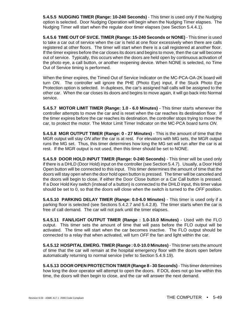
Revision 6.03 - ASME A17.1 -2000 Code Compliant THE COMPUTER • 5-49
5.4.5.5 NUDGING TIMER (Range: 10-240 Seconds) - This timer is used only if the Nudgingoption is selected. Door Nudging Operation will begin when the Nudging Timer elapses. TheNudging Timer will start when the regular door timer elapses (see Section 5.4.4.1).
5.4.5.6 TIME OUT OF SVCE. TIMER (Range: 15-240 Seconds or NONE) - This timer is usedto take a car out of service when the car is held at one floor excessively when there are callsregistered at other floors. The timer will start when there is a call registered at another floor.If the timer expires before the car closes its doors and begins to move, then the car will becomeout of service. Typically, this occurs when the doors are held open by continuous activation ofthe photo eye, a call button, or another reopening device. When NONE is selected, no TimeOut of Service timing is performed.
When the timer expires, the Timed Out of Service Indicator on the MC-PCA-OA-2K board willturn ON. The controller will ignore the PHE (Photo Eye) input, if the Stuck Photo EyeProtection option is selected. In duplexes, the car's assigned hall calls will be assigned to theother car. When the car closes its doors and begins to move again, it will go back into Normalservice.
5.4.5.7 MOTOR LIMIT TIMER (Range: 1.0 - 6.0 Minutes) - This timer starts whenever thecontroller attempts to move the car and is reset when the car reaches its destination floor. Ifthe timer expires before the car reaches its destination, the controller stops trying to move thecar, to protect the motor. The Motor Limit Timer Indicator on the MC-PCA board turns ON.
5.4.5.8 MGR OUTPUT TIMER (Range: 0 - 27 Minutes) - This is the amount of time that theMGR output will stay ON after the car is at rest. For elevators with MG sets, the MGR outputruns the MG set. Thus, this timer determines how long the MG set will run after the car is atrest. If the MGR output is not used, then this timer should be set to NONE.
5.4.5.9 DOOR HOLD INPUT TIMER (Range: 0-240 Seconds) - This timer will be used onlyif there is a DHLD (Door Hold) input on the controller (see Section 5.4.7). Usually, a Door HoldOpen button will be connected to this input. This timer determines the amount of time that thedoors will stay open when the door hold open button is pressed. The timer will be canceled andthe doors will begin to close, if either the Door Close button or a Car Call button is pressed.If a Door Hold Key switch (instead of a button) is connected to the DHLD input, this timer valueshould be set to 0, so that the doors will close when the switch is turned to the OFF position.
5.4.5.10 PARKING DELAY TIMER (Range: 0.0-6.0 Minutes) - This timer is used only if aparking floor is selected (see Sections 5.4.2.7 and 5.4.2.8). The timer starts when the car isfree of call demand. The car will not park until the timer elapses.
5.4.5.11 FAN/LIGHT OUTPUT TIMER (Range : 1.0-10.0 Minutes) - Used with the FLOoutput. This timer sets the amount of time that will pass before the FLO output will beactivated. The time will start when the car becomes inactive. The FLO output should beconnected to a relay that when activated, will turn OFF the fan and light within the car.
5.4.5.12 HOSPITAL EMERG. TIMER (Range : 0.0-10.0 Minutes) - This timer sets the amountof time that the car will remain at the hospital emergency floor with the doors open beforeautomatically returning to normal service (refer to Section 5.4.9.19).
5.4.5.13 DOOR OPEN PROTECTION TIMER (Range 8 - 30 Seconds) - This timer determineshow long the door operator will attempt to open the doors. If DOL does not go low within thistime, the doors will then begin to close, and the car will answer the next demand.
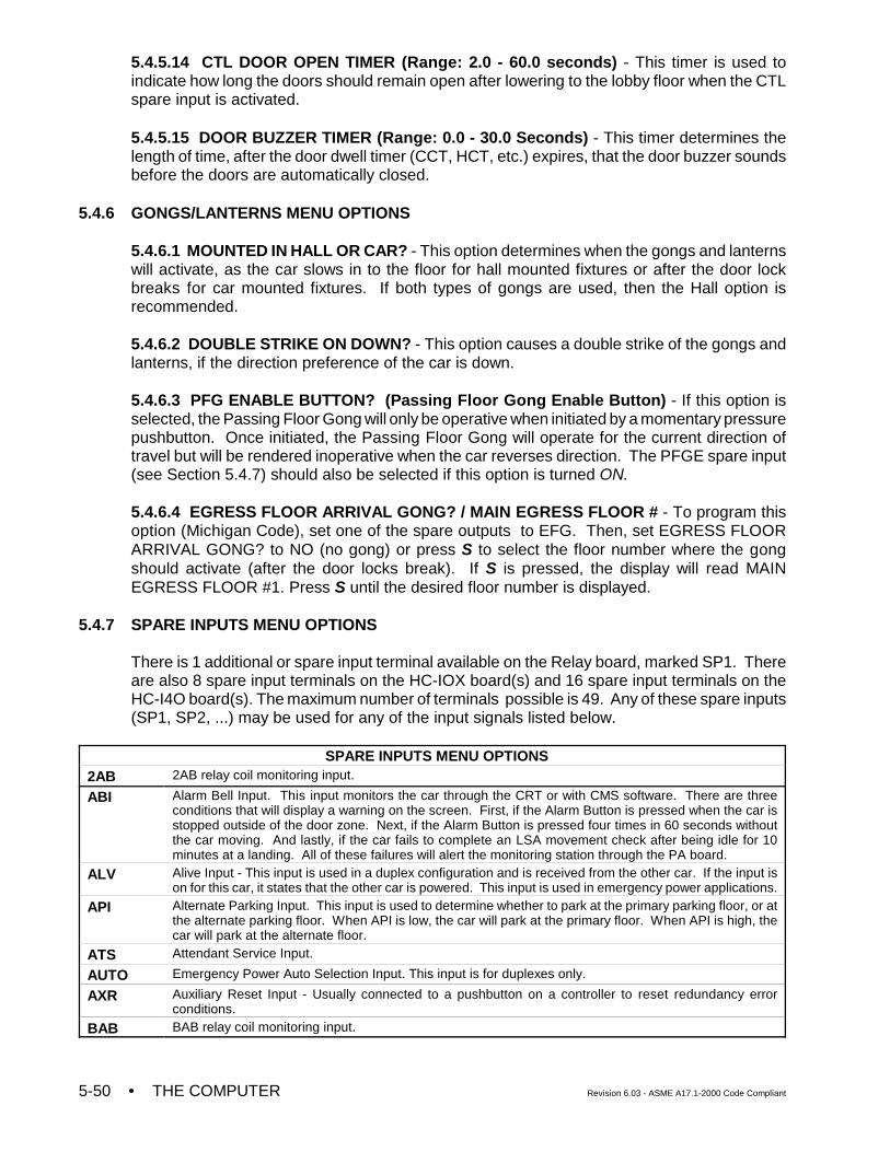
• THE COMPUTER Revision 6.03 - ASME A17.1-2000 Code Compliant5-50
5.4.5.14 CTL DOOR OPEN TIMER (Range: 2.0 - 60.0 seconds) - This timer is used toindicate how long the doors should remain open after lowering to the lobby floor when the CTLspare input is activated.
5.4.5.15 DOOR BUZZER TIMER (Range: 0.0 - 30.0 Seconds) - This timer determines thelength of time, after the door dwell timer (CCT, HCT, etc.) expires, that the door buzzer soundsbefore the doors are automatically closed.
5.4.6 GONGS/LANTERNS MENU OPTIONS
5.4.6.1 MOUNTED IN HALL OR CAR? - This option determines when the gongs and lanternswill activate, as the car slows in to the floor for hall mounted fixtures or after the door lockbreaks for car mounted fixtures. If both types of gongs are used, then the Hall option isrecommended.
5.4.6.2 DOUBLE STRIKE ON DOWN? - This option causes a double strike of the gongs andlanterns, if the direction preference of the car is down.
5.4.6.3 PFG ENABLE BUTTON? (Passing Floor Gong Enable Button) - If this option isselected, the Passing Floor Gong will only be operative when initiated by a momentary pressurepushbutton. Once initiated, the Passing Floor Gong will operate for the current direction oftravel but will be rendered inoperative when the car reverses direction. The PFGE spare input(see Section 5.4.7) should also be selected if this option is turned ON.
5.4.6.4 EGRESS FLOOR ARRIVAL GONG? / MAIN EGRESS FLOOR # - To program thisoption (Michigan Code), set one of the spare outputs to EFG. Then, set EGRESS FLOORARRIVAL GONG? to NO (no gong) or press S to select the floor number where the gongshould activate (after the door locks break). If S is pressed, the display will read MAINEGRESS FLOOR #1. Press S until the desired floor number is displayed.
5.4.7 SPARE INPUTS MENU OPTIONS
There is 1 additional or spare input terminal available on the Relay board, marked SP1. Thereare also 8 spare input terminals on the HC-IOX board(s) and 16 spare input terminals on theHC-I4O board(s). The maximum number of terminals possible is 49. Any of these spare inputs(SP1, SP2, ...) may be used for any of the input signals listed below.
SPARE INPUTS MENU OPTIONS2AB 2AB relay coil monitoring input.
ABI Alarm Bell Input. This input monitors the car through the CRT or with CMS software. There are threeconditions that will display a warning on the screen. First, if the Alarm Button is pressed when the car isstopped outside of the door zone. Next, if the Alarm Button is pressed four times in 60 seconds withoutthe car moving. And lastly, if the car fails to complete an LSA movement check after being idle for 10minutes at a landing. All of these failures will alert the monitoring station through the PA board.
ALV Alive Input - This input is used in a duplex configuration and is received from the other car. If the input ison for this car, it states that the other car is powered. This input is used in emergency power applications.
API Alternate Parking Input. This input is used to determine whether to park at the primary parking floor, or atthe alternate parking floor. When API is low, the car will park at the primary floor. When API is high, thecar will park at the alternate floor.
ATS Attendant Service Input.
AUTO Emergency Power Auto Selection Input. This input is for duplexes only.
AXR Auxiliary Reset Input - Usually connected to a pushbutton on a controller to reset redundancy errorconditions.
BAB BAB relay coil monitoring input.
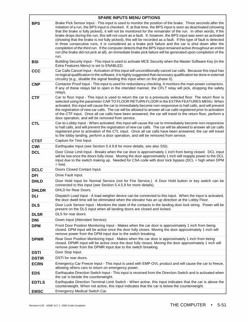
SPARE INPUTS MENU OPTIONS
Revision 6.03 - ASME A17.1 -2000 Code Compliant THE COMPUTER • 5-51
BPS Brake Pick Sensor Input - This input is used to monitor the position of the brake. Three seconds after theinitiation of a run, the BPS input is checked. If, at that time, the BPS input is seen as deactivated (showingthat the brake is fully picked), it will not be monitored for the remainder of the run. In other words, if thebrake drops during the run, this will not count as a fault. If, however, the BPS input was seen as activated(showing that the brake is not fully picked), this will be recorded as a fault. If this type of fault is detectedin three consecutive runs, it is considered as a brake pick failure and the car is shut down after thecompletion of the third run. If the computer detects that the BPS input remained active throughout an entirerun (the brake did not pick at all), an immediate brake pick failure will be generated upon completion of therun.
BSI Building Security Input - This input is used to activate MCE Security when the Master Software Key (in theExtra Features Menu) is set to ENABLED.
CCC Car Calls Cancel Input - Activation of this input will unconditionally cancel car calls. Because this input hasno logical qualification in the software, it is highly suggested that necessary qualification be done in externalcircuitry (e.g., disable the signal feeding this input when on fire phase II).
CNP Contactor Proof Input - This input is used for redundancy checking. It monitors the main power contactors.If any of these relays fail to open in the intended manner, the CFLT relay will pick, dropping the safetyrelays.
CTF Car to floor Input - This input is used to return the car to a previously selected floor. The return floor isselected using the parameter CAR TO FLOOR RETURN FLOOR in the EXTRA FEATURES MENU. Whenactivated, this input will cause the car to immediately become non-responsive to hall calls, and will preventthe registration of new car calls. The car will be allowed to answer all car calls registered prior to activationof the CTF input. Once all car calls have been answered, the car will travel to the return floor, perform adoor operation, and will be removed from service.
CTL Car-to-Lobby Input - When activated, this input will cause the car to immediately become non-responsiveto hall calls, and will prevent the registration of new car calls. The car will be allowed to answer all car callsregistered prior to activation of the CTL input. Once all car calls have been answered, the car will travelto the lobby landing, perform a door operation, and will be removed from service.
CTST Capture for Test Input.
CWI Earthquake Input (see Section 5.4.9.8 for more details, see also SSI).
DCL Door Close Limit Input - Breaks when the car door is approximately 1 inch from being closed. DCL inputwill be low once the doors fully close. Moving the door approximately 1 inch will reapply power to the DCLinput due to the switch making up. Needed for CSA code with door lock bypass (DCL = high when DPM= low).
DCLC Doors Closed Contact Input.
DFI Drive Fault Input.
DHLD Door Hold Input for Normal Service (not for Fire Service.) A Door Hold button or key switch can beconnected to this input (see Section 5.4.5.9 for more details).
DHLDR DHLD for Rear Doors.
DLI Dispatch Load Input - A load weigher device can be connected to this input. When the input is activated,the door dwell time will be eliminated when the elevator has an up direction at the Lobby Floor.
DLS Door Lock Sensor Input - Monitors the state of the contacts in the landing door lock string. Power will bepresent on the DLS input when all landing doors are closed and locked.
DLSR DLS for rear doors.
DNI Down Input (Attendant Service).
DPM Front Door Position Monitoring Input - Makes when the car door is approximately 1 inch from beingclosed. DPM input will be active once the door fully closes. Moving the door approximately 1 inch willremove power from the DPM input due to the switch breaking.
DPMR Rear Door Position Monitoring Input - Makes when the car door is approximately 1 inch from beingclosed. DPMR input will be active once the door fully closes. Moving the door approximately 1 inch willremove power from the DPMR input due to the switch breaking.
DSTI Door Stop Input.
DSTIR DSTI for rear doors.
ECRN Emergency Car Freeze Input - This input is used with EMP-OVL product and will cause the car to freeze,allowing others cars to return on emergency power.
EDS Earthquake Direction Switch Input - This input is received from the Direction Switch and is activated whenthe car is beside the counterweight.
EDTLS Earthquake Direction Terminal Limit Switch - When active, this input indicates that the car is above thecounterweight. When not active, this input indicates that the car is below the counterweight.
EMSC Emergency Medical Switch Car.
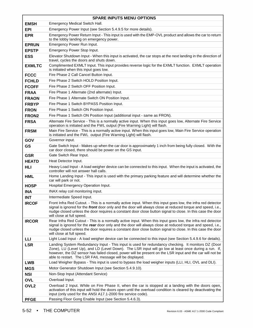
SPARE INPUTS MENU OPTIONS
• THE COMPUTER Revision 6.03 - ASME A17.1-2000 Code Compliant5-52
EMSH Emergency Medical Switch Hall.
EPI Emergency Power Input (see Section 5.4.9.5 for more details).
EPR Emergency Power Return Input - This input is used with the EMP-OVL product and allows the car to returnto the lobby landing on emergency power.
EPRUN Emergency Power Run Input.
EPSTP Emergency Power Stop Input.
ESS Elevator Shutdown Input - When this input is activated, the car stops at the next landing in the direction oftravel, cycles the doors and shuts down.
EXMLTC Complimented EXMLT Input. This input provides reverse logic for the EXMLT function. EXMLT operationis initiated when this input goes low.
FCCC Fire Phase 2 Call Cancel Button Input.
FCHLD Fire Phase 2 Switch HOLD Position Input.
FCOFF Fire Phase 2 Switch OFF Position Input.
FRAA Fire Phase 1 Alternate (2nd alternate) Input.
FRAON Fire Phase 1 Alternate Switch ON Position Input.
FRBYP Fire Phase 1 Switch BYPASS Position Input.
FRON Fire Phase 1 Switch ON Position Input.
FRON2 Fire Phase 1 Switch ON Position Input (additional input - same as FRON).
FRSA Alternate Fire Service - This is a normally active input. When this input goes low, Alternate Fire Serviceoperation is initiated and the FWL output (Fire Warning Light) will flash.
FRSM Main Fire Service - This is a normally active input. When this input goes low, Main Fire Service operationis initiated and the FWL output (Fire Warning Light) will flash.
GOV Governor input.
GS Gate Switch Input - Makes up when the car door is approximately 1 inch from being fully closed. With thecar door closed, there should be power on the GS input.
GSR Gate Switch Rear Input.
HEATD Heat Detector Input.
HLI Heavy Load Input - A load weigher device can be connected to this input. When the input is activated, thecontroller will not answer hall calls.
HML Home Landing Input - This input is used with the primary parking feature and will determine whether thecar will park or not.
HOSP Hospital Emergency Operation Input.
INA INAX relay coil monitoring input.
INT Intermediate Speed Input.
IRCOF Front Infra Red Cutout. - This is a normally active input. When this input goes low, the infra red detectorsignal is ignored for the front door only and the door will always close at reduced torque and speed, i.e.,nudge closed unless the door requires a constant door close button signal to close. In this case the doorwill close at full speed.
IRCOR Rear Infra Red Cutout - This is a normally active input. When this input goes low, the infra red detectorsignal is ignored for the rear door only and the door will always close at reduced torque and speed, i.e.,nudge closed unless the door requires a constant door close button signal to close. In this case the doorwill close at full speed.
LLI Light Load Input - A load weigher device can be connected to this input (see Section 5.4.9.6 for details).
LSR Landing System Redundancy Input - This input is used for redundancy checking. It monitors DZ (DoorZone), LU (Level Up), and LD (Level Down). The LSR input will go low at least once during a run. If,however, the DZ sensor has failed closed, power will be present on the LSR input and the car will not beable to restart. The LSR FAIL message will be displayed.
LWB Load Weigher Bypass - This input is used to bypass the load weigher inputs (LLI, HLI, OVL and DLI).
MGS Motor Generator Shutdown Input (see Section 5.4.9.10).
NSI Non-Stop Input (Attendant Service)
OVL Overload Input.
OVL2 Overload 2 Input. While on Fire Phase II, when the car is stopped at a landing with the doors open,activation of this input will hold the doors open until the overload condition is cleared by deactivating theinput (only used for the ANSI A17.1-2000 fire service code).
PFGE Passing Floor Gong Enable Input (see Section 5.4.6.3).
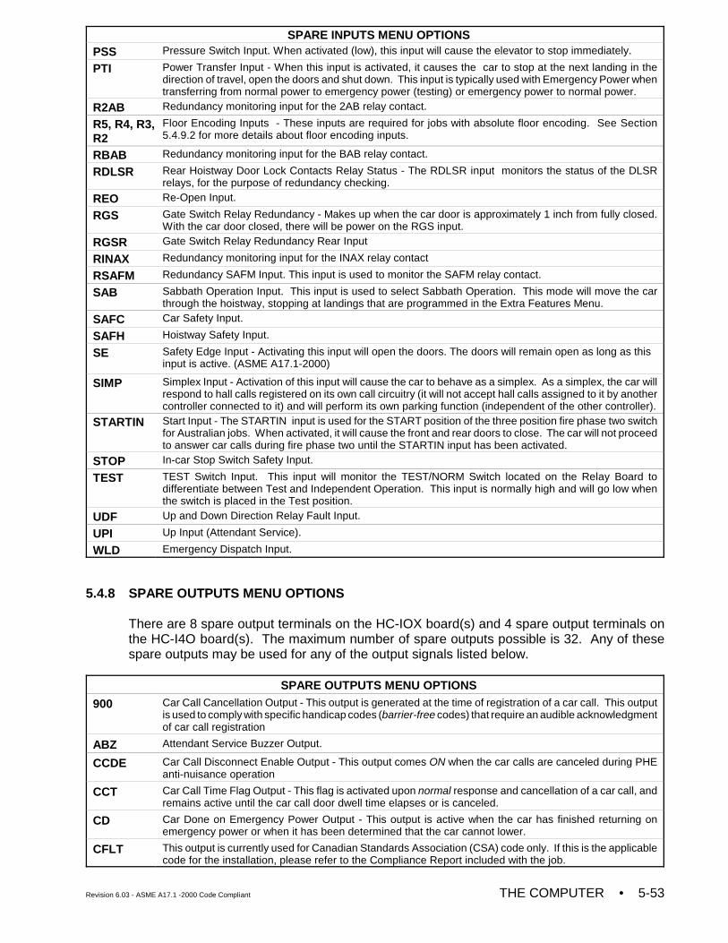
SPARE INPUTS MENU OPTIONS
Revision 6.03 - ASME A17.1 -2000 Code Compliant THE COMPUTER • 5-53
PSS Pressure Switch Input. When activated (low), this input will cause the elevator to stop immediately.
PTI Power Transfer Input - When this input is activated, it causes the car to stop at the next landing in thedirection of travel, open the doors and shut down. This input is typically used with Emergency Power whentransferring from normal power to emergency power (testing) or emergency power to normal power.
R2AB Redundancy monitoring input for the 2AB relay contact.
R5, R4, R3,R2
Floor Encoding Inputs - These inputs are required for jobs with absolute floor encoding. See Section5.4.9.2 for more details about floor encoding inputs.
RBAB Redundancy monitoring input for the BAB relay contact.
RDLSR Rear Hoistway Door Lock Contacts Relay Status - The RDLSR input monitors the status of the DLSRrelays, for the purpose of redundancy checking.
REO Re-Open Input.
RGS Gate Switch Relay Redundancy - Makes up when the car door is approximately 1 inch from fully closed.With the car door closed, there will be power on the RGS input.
RGSR Gate Switch Relay Redundancy Rear Input
RINAX Redundancy monitoring input for the INAX relay contact
RSAFM Redundancy SAFM Input. This input is used to monitor the SAFM relay contact.
SAB Sabbath Operation Input. This input is used to select Sabbath Operation. This mode will move the carthrough the hoistway, stopping at landings that are programmed in the Extra Features Menu.
SAFC Car Safety Input.
SAFH Hoistway Safety Input.
SE Safety Edge Input - Activating this input will open the doors. The doors will remain open as long as thisinput is active. (ASME A17.1-2000)
SIMP Simplex Input - Activation of this input will cause the car to behave as a simplex. As a simplex, the car willrespond to hall calls registered on its own call circuitry (it will not accept hall calls assigned to it by anothercontroller connected to it) and will perform its own parking function (independent of the other controller).
STARTIN Start Input - The STARTIN input is used for the START position of the three position fire phase two switchfor Australian jobs. When activated, it will cause the front and rear doors to close. The car will not proceedto answer car calls during fire phase two until the STARTIN input has been activated.
STOP In-car Stop Switch Safety Input.
TEST TEST Switch Input. This input will monitor the TEST/NORM Switch located on the Relay Board todifferentiate between Test and Independent Operation. This input is normally high and will go low whenthe switch is placed in the Test position.
UDF Up and Down Direction Relay Fault Input.
UPI Up Input (Attendant Service).
WLD Emergency Dispatch Input.
5.4.8 SPARE OUTPUTS MENU OPTIONS
There are 8 spare output terminals on the HC-IOX board(s) and 4 spare output terminals onthe HC-I4O board(s). The maximum number of spare outputs possible is 32. Any of thesespare outputs may be used for any of the output signals listed below.
SPARE OUTPUTS MENU OPTIONS
900 Car Call Cancellation Output - This output is generated at the time of registration of a car call. This outputis used to comply with specific handicap codes (barrier-free codes) that require an audible acknowledgmentof car call registration
ABZ Attendant Service Buzzer Output.
CCDE Car Call Disconnect Enable Output - This output comes ON when the car calls are canceled during PHEanti-nuisance operation
CCT Car Call Time Flag Output - This flag is activated upon normal response and cancellation of a car call, andremains active until the car call door dwell time elapses or is canceled.
CD Car Done on Emergency Power Output - This output is active when the car has finished returning onemergency power or when it has been determined that the car cannot lower.
CFLT This output is currently used for Canadian Standards Association (CSA) code only. If this is the applicablecode for the installation, please refer to the Compliance Report included with the job.
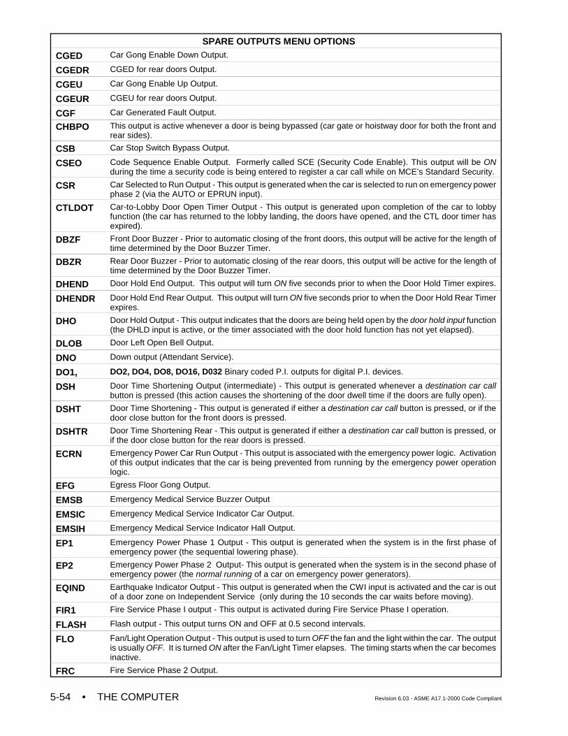
SPARE OUTPUTS MENU OPTIONS
• THE COMPUTER Revision 6.03 - ASME A17.1-2000 Code Compliant5-54
CGED Car Gong Enable Down Output.
CGEDR CGED for rear doors Output.
CGEU Car Gong Enable Up Output.
CGEUR CGEU for rear doors Output.
CGF Car Generated Fault Output.
CHBPO This output is active whenever a door is being bypassed (car gate or hoistway door for both the front andrear sides).
CSB Car Stop Switch Bypass Output.
CSEO Code Sequence Enable Output. Formerly called SCE (Security Code Enable). This output will be ONduring the time a security code is being entered to register a car call while on MCE’s Standard Security.
CSR Car Selected to Run Output - This output is generated when the car is selected to run on emergency powerphase 2 (via the AUTO or EPRUN input).
CTLDOT Car-to-Lobby Door Open Timer Output - This output is generated upon completion of the car to lobbyfunction (the car has returned to the lobby landing, the doors have opened, and the CTL door timer hasexpired).
DBZF Front Door Buzzer - Prior to automatic closing of the front doors, this output will be active for the length oftime determined by the Door Buzzer Timer.
DBZR Rear Door Buzzer - Prior to automatic closing of the rear doors, this output will be active for the length oftime determined by the Door Buzzer Timer.
DHEND Door Hold End Output. This output will turn ON five seconds prior to when the Door Hold Timer expires.
DHENDR Door Hold End Rear Output. This output will turn ON five seconds prior to when the Door Hold Rear Timerexpires.
DHO Door Hold Output - This output indicates that the doors are being held open by the door hold input function(the DHLD input is active, or the timer associated with the door hold function has not yet elapsed).
DLOB Door Left Open Bell Output.
DNO Down output (Attendant Service).
DO1, DO2, DO4, DO8, DO16, D032 Binary coded P.I. outputs for digital P.I. devices.
DSH Door Time Shortening Output (intermediate) - This output is generated whenever a destination car callbutton is pressed (this action causes the shortening of the door dwell time if the doors are fully open).
DSHT Door Time Shortening - This output is generated if either a destination car call button is pressed, or if thedoor close button for the front doors is pressed.
DSHTR Door Time Shortening Rear - This output is generated if either a destination car call button is pressed, orif the door close button for the rear doors is pressed.
ECRN Emergency Power Car Run Output - This output is associated with the emergency power logic. Activationof this output indicates that the car is being prevented from running by the emergency power operationlogic.
EFG Egress Floor Gong Output.
EMSB Emergency Medical Service Buzzer Output
EMSIC Emergency Medical Service Indicator Car Output.
EMSIH Emergency Medical Service Indicator Hall Output.
EP1 Emergency Power Phase 1 Output - This output is generated when the system is in the first phase ofemergency power (the sequential lowering phase).
EP2 Emergency Power Phase 2 Output- This output is generated when the system is in the second phase ofemergency power (the normal running of a car on emergency power generators).
EQIND Earthquake Indicator Output - This output is generated when the CWI input is activated and the car is outof a door zone on Independent Service (only during the 10 seconds the car waits before moving).
FIR1 Fire Service Phase I output - This output is activated during Fire Service Phase I operation.
FLASH Flash output - This output turns ON and OFF at 0.5 second intervals.
FLO Fan/Light Operation Output - This output is used to turn OFF the fan and the light within the car. The outputis usually OFF. It is turned ON after the Fan/Light Timer elapses. The timing starts when the car becomesinactive.
FRC Fire Service Phase 2 Output.
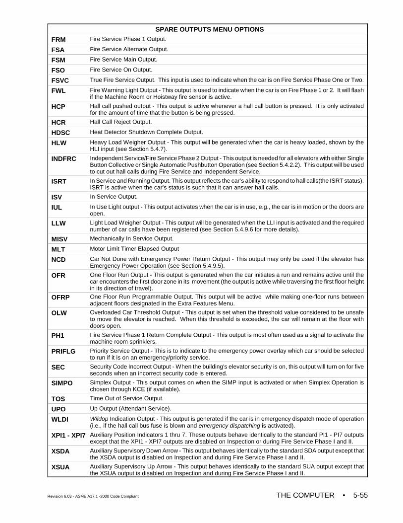
SPARE OUTPUTS MENU OPTIONS
Revision 6.03 - ASME A17.1 -2000 Code Compliant THE COMPUTER • 5-55
FRM Fire Service Phase 1 Output.
FSA Fire Service Alternate Output.
FSM Fire Service Main Output.
FSO Fire Service On Output.
FSVC True Fire Service Output. This input is used to indicate when the car is on Fire Service Phase One or Two.
FWL Fire Warning Light Output - This output is used to indicate when the car is on Fire Phase 1 or 2. It will flashif the Machine Room or Hoistway fire sensor is active.
HCP Hall call pushed output - This output is active whenever a hall call button is pressed. It is only activatedfor the amount of time that the button is being pressed.
HCR Hall Call Reject Output.
HDSC Heat Detector Shutdown Complete Output.
HLW Heavy Load Weigher Output - This output will be generated when the car is heavy loaded, shown by theHLI input (see Section 5.4.7).
INDFRC Independent Service/Fire Service Phase 2 Output - This output is needed for all elevators with either SingleButton Collective or Single Automatic Pushbutton Operation (see Section 5.4.2.2). This output will be usedto cut out hall calls during Fire Service and Independent Service.
ISRT In Service and Running Output. This output reflects the car’s ability to respond to hall calls(the ISRT status).ISRT is active when the car’s status is such that it can answer hall calls.
ISV In Service Output.
IUL In Use Light output - This output activates when the car is in use, e.g., the car is in motion or the doors areopen.
LLW Light Load Weigher Output - This output will be generated when the LLI input is activated and the requirednumber of car calls have been registered (see Section 5.4.9.6 for more details).
MISV Mechanically In Service Output.
MLT Motor Limit Timer Elapsed Output
NCD Car Not Done with Emergency Power Return Output - This output may only be used if the elevator hasEmergency Power Operation (see Section 5.4.9.5).
OFR One Floor Run Output - This output is generated when the car initiates a run and remains active until thecar encounters the first door zone in its movement (the output is active while traversing the first floor heightin its direction of travel).
OFRP One Floor Run Programmable Output. This output will be active while making one-floor runs betweenadjacent floors designated in the Extra Features Menu.
OLW Overloaded Car Threshold Output - This output is set when the threshold value considered to be unsafeto move the elevator is reached. When this threshold is exceeded, the car will remain at the floor withdoors open.
PH1 Fire Service Phase 1 Return Complete Output - This output is most often used as a signal to activate themachine room sprinklers.
PRIFLG Priority Service Output - This is to indicate to the emergency power overlay which car should be selectedto run if it is on an emergency/priority service.
SEC Security Code Incorrect Output - When the building's elevator security is on, this output will turn on for fiveseconds when an incorrect security code is entered.
SIMPO Simplex Output - This output comes on when the SIMP input is activated or when Simplex Operation ischosen through KCE (if available).
TOS Time Out of Service Output.
UPO Up Output (Attendant Service).
WLDI Wildop Indication Output - This output is generated if the car is in emergency dispatch mode of operation(i.e., if the hall call bus fuse is blown and emergency dispatching is activated).
XPI1 - XPI7 Auxiliary Position Indicators 1 thru 7. These outputs behave identically to the standard PI1 - PI7 outputsexcept that the XPI1 - XPI7 outputs are disabled on Inspection or during Fire Service Phase I and II.
XSDA Auxiliary Supervisory Down Arrow - This output behaves identically to the standard SDA output except thatthe XSDA output is disabled on Inspection and during Fire Service Phase I and II.
XSUA Auxiliary Supervisory Up Arrow - This output behaves identically to the standard SUA output except thatthe XSUA output is disabled on Inspection and during Fire Service Phase I and II.
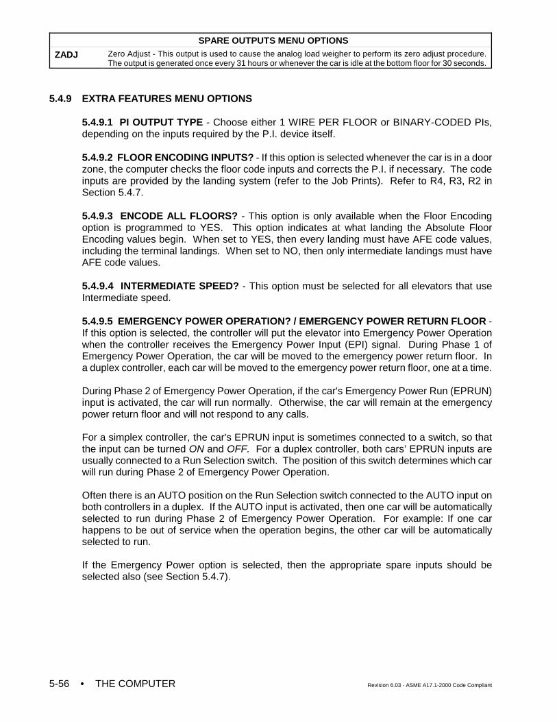
SPARE OUTPUTS MENU OPTIONS
• THE COMPUTER Revision 6.03 - ASME A17.1-2000 Code Compliant5-56
ZADJ Zero Adjust - This output is used to cause the analog load weigher to perform its zero adjust procedure.The output is generated once every 31 hours or whenever the car is idle at the bottom floor for 30 seconds.
5.4.9 EXTRA FEATURES MENU OPTIONS
5.4.9.1 PI OUTPUT TYPE - Choose either 1 WIRE PER FLOOR or BINARY-CODED PIs,depending on the inputs required by the P.I. device itself.
5.4.9.2 FLOOR ENCODING INPUTS? - If this option is selected whenever the car is in a doorzone, the computer checks the floor code inputs and corrects the P.I. if necessary. The codeinputs are provided by the landing system (refer to the Job Prints). Refer to R4, R3, R2 inSection 5.4.7.
5.4.9.3 ENCODE ALL FLOORS? - This option is only available when the Floor Encodingoption is programmed to YES. This option indicates at what landing the Absolute FloorEncoding values begin. When set to YES, then every landing must have AFE code values,including the terminal landings. When set to NO, then only intermediate landings must haveAFE code values.
5.4.9.4 INTERMEDIATE SPEED? - This option must be selected for all elevators that useIntermediate speed.
5.4.9.5 EMERGENCY POWER OPERATION? / EMERGENCY POWER RETURN FLOOR -If this option is selected, the controller will put the elevator into Emergency Power Operationwhen the controller receives the Emergency Power Input (EPI) signal. During Phase 1 ofEmergency Power Operation, the car will be moved to the emergency power return floor. Ina duplex controller, each car will be moved to the emergency power return floor, one at a time.
During Phase 2 of Emergency Power Operation, if the car's Emergency Power Run (EPRUN)input is activated, the car will run normally. Otherwise, the car will remain at the emergencypower return floor and will not respond to any calls.
For a simplex controller, the car's EPRUN input is sometimes connected to a switch, so thatthe input can be turned ON and OFF. For a duplex controller, both cars’ EPRUN inputs areusually connected to a Run Selection switch. The position of this switch determines which carwill run during Phase 2 of Emergency Power Operation.
Often there is an AUTO position on the Run Selection switch connected to the AUTO input onboth controllers in a duplex. If the AUTO input is activated, then one car will be automaticallyselected to run during Phase 2 of Emergency Power Operation. For example: If one carhappens to be out of service when the operation begins, the other car will be automaticallyselected to run.
If the Emergency Power option is selected, then the appropriate spare inputs should beselected also (see Section 5.4.7).
Revision 6.03 - ASME A17.1 -2000 Code Compliant THE COMPUTER • 5-57
5.4.9.6 LIGHT LOAD WEIGHING? / LIGHT LOAD CAR CALL LIMIT - This option is only usedwhen the Light Load Weigher Input is activated (refer to Section 5.4.7, LLI spare input). Toprogram this option, activate the LLI input. Then, set LIGHT LOAD WEIGHING? to NO or pressS to select the maximum number of car calls registered before all the car calls are canceled.If S is pressed, the display will read LIGHT LOAD CAR CALL LIMIT. Press S until the desirednumber is displayed.
5.4.9.7 PHOTO EYE ANTI-NUISANCE? / CONSEC STOPS W/O PHE LIMIT - When thisoption is ON, the car calls will cancel if the Photo Eye input has not been activated after aprogrammed number of consecutive stops. The number of consecutive stops must beprogrammed before the car calls will cancel. To program this option, set PHOTO EYE ANTI-NUISANCE? to NO or press S to select the number of consecutive stops. If S is pressed, thedisplay will read CONSEC STOPS W/O PHE LIMIT. Press S until the desired number isdisplayed.
5.4.9.8 EARTHQUAKE OPERATION - The controller should be equipped with the propercircuitry before selecting the inputs needed for Earthquake Operation. This option can be setto ANSI EARTHQUAKE OPERATION or CALIFORNIA EARTHQUAKE OPERATION.Descriptions of these options follow.
1. ANSI EARTHQUAKE OPERATION - When ANSI Earthquake Operation is selectedupon activation of a Seismic switch (EQI input), the elevator in motion will continue tothe nearest available floor at a speed of not more than 150 ft/min (0.76 m/s), open thedoors and shut down. If the Counterweight Displacement switch is not activated (CWI),the elevator will be allowed to run at reduced speed on Automatic Operation.
If the elevator is in motion when the Counterweight Displacement switch is activated(CWI input) an emergency stop is initiated and then the car will proceed away from thecounterweight at reduced speed to the nearest available floor, open the doors and shutdown. For this operation the Earthquake Direction Switch input (EDS) must be selected(see Section 5.4.7). An elevator may be returned to Normal service by means of theMomentary Reset button on the HC-EQ2 board, provided that the Displacement switch(CWI) is no longer activated.
2. CALIFORNIA EARTHQUAKE OPERATION - When CALIF Earthquake Operation isselected upon activation of a Seismic switch (EQI input), the elevator, if in motion, willproceed to the nearest available floor at a speed of not more than 150 ft/min (0.76 m/s)open the doors and shut down.
When a Counterweight Displacement switch is required and the CounterweightDisplacement switch (CWI input) has been activated, the elevator, if in motion, willinitiate an emergency stop and proceed away from the counterweight at reduced speedto the nearest available floor, open the doors and shut down. For this operation, theEarthquake Direction Switch (EDS) input must be selected (see Section 5.4.7). Anelevator may be returned to Normal service by means of the Momentary Reset buttonon the HC-EQ2 board, provided that the Displacement switch (CWI) is not activated.When Earthquake Operation is needed, the appropriate spare inputs should beselected (see Section 5.4.7).
5.4.9.9 COUNTERWEIGHTED DRUM MACHINE? - Only jobs that are termed“Counterweighted Drum Machines” should set this option to Yes. For normal California jobs,this option should be set to NO. When set to YES it indicates that there is only one Earthquakeinput, EQI. When activated, EQI will shut down the elevator and will not move it until EQI isreset. Once deactivated, the car will move to the next landing and cycle the doors beforereturning to normal operation.
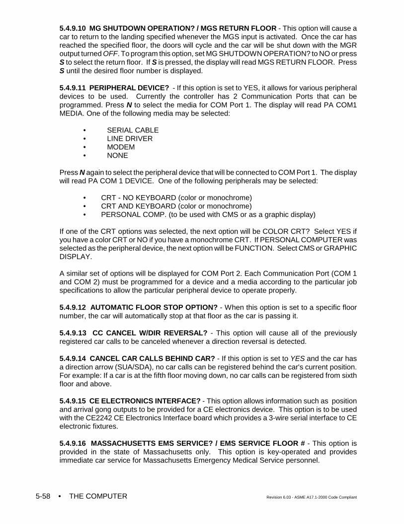
• THE COMPUTER Revision 6.03 - ASME A17.1-2000 Code Compliant5-58
5.4.9.10 MG SHUTDOWN OPERATION? / MGS RETURN FLOOR - This option will cause acar to return to the landing specified whenever the MGS input is activated. Once the car hasreached the specified floor, the doors will cycle and the car will be shut down with the MGRoutput turned OFF. To program this option, set MG SHUTDOWN OPERATION? to NO or pressS to select the return floor. If S is pressed, the display will read MGS RETURN FLOOR. PressS until the desired floor number is displayed.
5.4.9.11 PERIPHERAL DEVICE? - If this option is set to YES, it allows for various peripheraldevices to be used. Currently the controller has 2 Communication Ports that can beprogrammed. Press N to select the media for COM Port 1. The display will read PA COM1MEDIA. One of the following media may be selected:
• SERIAL CABLE• LINE DRIVER• MODEM• NONE
Press N again to select the peripheral device that will be connected to COM Port 1. The displaywill read PA COM 1 DEVICE. One of the following peripherals may be selected:
• CRT - NO KEYBOARD (color or monochrome)• CRT AND KEYBOARD (color or monochrome)• PERSONAL COMP. (to be used with CMS or as a graphic display)
If one of the CRT options was selected, the next option will be COLOR CRT? Select YES ifyou have a color CRT or NO if you have a monochrome CRT. If PERSONAL COMPUTER wasselected as the peripheral device, the next option will be FUNCTION. Select CMS or GRAPHICDISPLAY.
A similar set of options will be displayed for COM Port 2. Each Communication Port (COM 1and COM 2) must be programmed for a device and a media according to the particular jobspecifications to allow the particular peripheral device to operate properly.
5.4.9.12 AUTOMATIC FLOOR STOP OPTION? - When this option is set to a specific floornumber, the car will automatically stop at that floor as the car is passing it.
5.4.9.13 CC CANCEL W/DIR REVERSAL? - This option will cause all of the previouslyregistered car calls to be canceled whenever a direction reversal is detected.
5.4.9.14 CANCEL CAR CALLS BEHIND CAR? - If this option is set to YES and the car hasa direction arrow (SUA/SDA), no car calls can be registered behind the car's current position.For example: If a car is at the fifth floor moving down, no car calls can be registered from sixthfloor and above.
5.4.9.15 CE ELECTRONICS INTERFACE? - This option allows information such as positionand arrival gong outputs to be provided for a CE electronics device. This option is to be usedwith the CE2242 CE Electronics Interface board which provides a 3-wire serial interface to CEelectronic fixtures.
5.4.9.16 MASSACHUSETTS EMS SERVICE? / EMS SERVICE FLOOR # - This option isprovided in the state of Massachusetts only. This option is key-operated and providesimmediate car service for Massachusetts Emergency Medical Service personnel.
Revision 6.03 - ASME A17.1 -2000 Code Compliant THE COMPUTER • 5-59
5.4.9.17 MASTER SOFTWARE KEY - This option is a board-level control of the securitysystem. MCE Security is initiated by the Master Software Key. There are three possiblesettings for the Master Software Key: ACTIVATED, ENABLED, and DEACTIVATED.
• If set to ACTIVATED, Security is initiated. • If set to ENABLED, Security is initiated if the Building Security Input (BSI) is ON.• If set to DEACTIVATED, Security is deactivated regardless of the status of the
BSI input.
5.4.9.18 PI TURNED OFF IF NO DEMAND? - Setting this option to yes will allow the PIoutputs to turn OFF if the car has been inactive for an adjustable time (from 1 to 10 minutes)
5.4.9.19 HOSPITAL EMERG. OPERATION? - This option calls any eligible in-service elevatorto any floor on an emergency basis. If this installation has Hospital Emergency ServiceOperation, a hospital emergency call switch will be installed at each floor where this service isdesired.
When the hospital emergency momentary call switch is activated at any floor, the hospitalemergency call registered light will illuminate at that floor only, and the nearest availableelevator will respond to the hospital emergency call. All car calls within the selected car will becanceled and any landing calls which had previously been assigned to that car will betransferred to the other car. If the selected car is traveling away from the hospital emergencycall, it will slow down and stop at the nearest floor without opening the doors, reverse direction,and proceed nonstop to the hospital emergency floor. If the selected car is traveling toward thehospital emergency floor, it shall proceed nonstop to that floor. At the time of selection, if thecar happens to slow down for a stop, it will stop without opening the doors and then startimmediately toward the hospital emergency floor.When the car reaches the hospital emergency floor, it will remain with doors open for a pre-determined time interval. After this interval has expired, if the car has not been placed on in-carHospital Emergency Service Operation, the car will automatically return to normal service.
A hospital emergency key switch will be located in each car operating station for selecting in-car Hospital Emergency Service Operation. Upon activation of the key switch, the car will beready to accept a call for any floor, and after the doors are closed, will proceed nonstop to thatfloor. Returning the key switch to the normal position will restore the car to normal service.
Either car selected to respond to a hospital emergency call will be removed from automaticservice and will accept no additional calls, emergency or otherwise, until it completes the initialhospital emergency function. If both cars are out of service and unable to answer anemergency call, the hospital emergency call registered light will not illuminate.
Four outputs are available on the first HC-CI/O-E board used for the hospital emergencyservice calls. Hospital Emergency Operation (HEO) will flash once the car has been selectedto respond to a hospital emergency call and will remain flashing until the in-car hospital switchis returned to normal or the time interval that the car must wait for the in-car switch to be turnedON expires. Hospital Emergency Warning Indicator (HWI) will remain steadily ON for a car onIndependent Service when the hospital call is registered. Hospital Emergency Select (HSEL)will remain steadily ON, indicating that the car has been selected to answer a hospital call, untilthe in-car hospital switch is turned ON or the time interval expires. Hospital Emergency Phase2 (HOSPH2) will remain ON, indicating that the car has arrived at the floor where the hospitalcall was registered, until the in-car hospital switch is returned to normal or the time interval thatthe car must wait for the in-car switch to be turned ON expires.
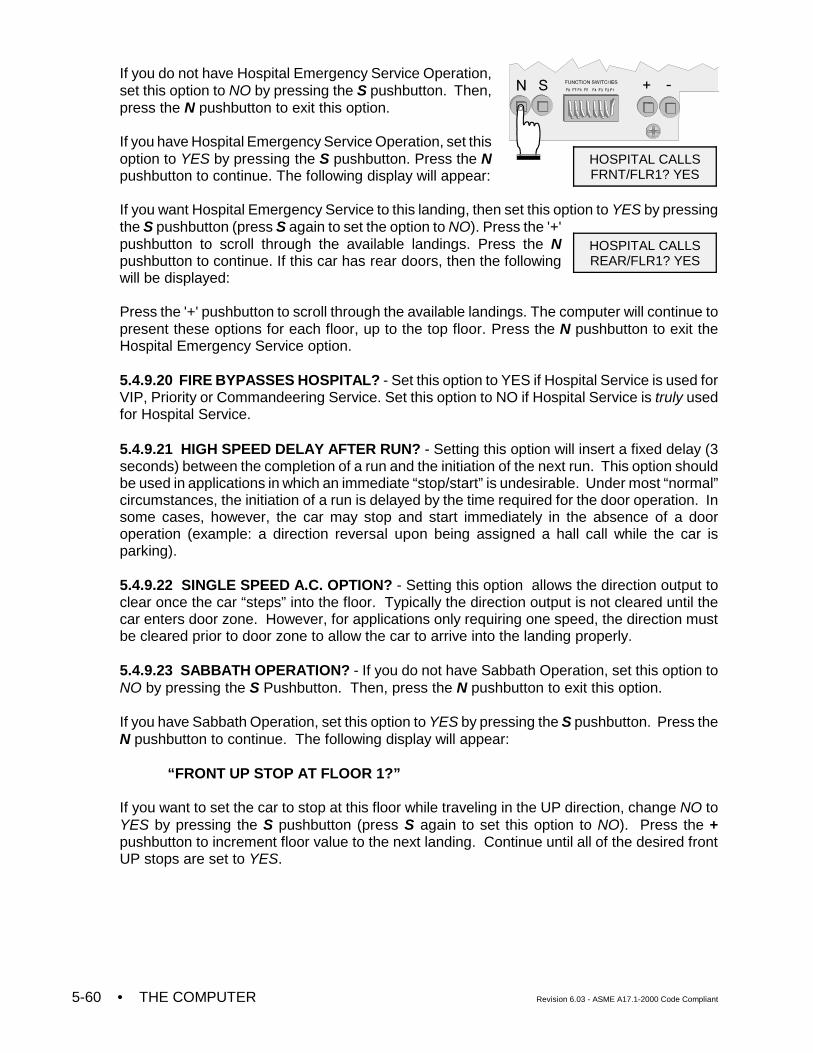
• THE COMPUTER Revision 6.03 - ASME A17.1-2000 Code Compliant5-60
If you do not have Hospital Emergency Service Operation,set this option to NO by pressing the S pushbutton. Then,press the N pushbutton to exit this option.
If you have Hospital Emergency Service Operation, set thisoption to YES by pressing the S pushbutton. Press the Npushbutton to continue. The following display will appear:
If you want Hospital Emergency Service to this landing, then set this option to YES by pressingthe S pushbutton (press S again to set the option to NO). Press the '+'pushbutton to scroll through the available landings. Press the Npushbutton to continue. If this car has rear doors, then the followingwill be displayed:
Press the '+' pushbutton to scroll through the available landings. The computer will continue topresent these options for each floor, up to the top floor. Press the N pushbutton to exit theHospital Emergency Service option.
5.4.9.20 FIRE BYPASSES HOSPITAL? - Set this option to YES if Hospital Service is used forVIP, Priority or Commandeering Service. Set this option to NO if Hospital Service is truly usedfor Hospital Service.
5.4.9.21 HIGH SPEED DELAY AFTER RUN? - Setting this option will insert a fixed delay (3seconds) between the completion of a run and the initiation of the next run. This option shouldbe used in applications in which an immediate “stop/start” is undesirable. Under most “normal”circumstances, the initiation of a run is delayed by the time required for the door operation. Insome cases, however, the car may stop and start immediately in the absence of a dooroperation (example: a direction reversal upon being assigned a hall call while the car isparking).
5.4.9.22 SINGLE SPEED A.C. OPTION? - Setting this option allows the direction output toclear once the car “steps” into the floor. Typically the direction output is not cleared until thecar enters door zone. However, for applications only requiring one speed, the direction mustbe cleared prior to door zone to allow the car to arrive into the landing properly.
5.4.9.23 SABBATH OPERATION? - If you do not have Sabbath Operation, set this option toNO by pressing the S Pushbutton. Then, press the N pushbutton to exit this option.
If you have Sabbath Operation, set this option to YES by pressing the S pushbutton. Press theN pushbutton to continue. The following display will appear:
“FRONT UP STOP AT FLOOR 1?”
If you want to set the car to stop at this floor while traveling in the UP direction, change NO toYES by pressing the S pushbutton (press S again to set this option to NO). Press the +pushbutton to increment floor value to the next landing. Continue until all of the desired frontUP stops are set to YES.
HOSPITAL CALLSFRNT/FLR1? YES
HOSPITAL CALLSREAR/FLR1? YES
Revision 6.03 - ASME A17.1 -2000 Code Compliant THE COMPUTER • 5-61
Press the N pushbutton to proceed to the next eligibility map. If “walk through doors” are notprogrammed on this controller, then rear eligibility maps will not display. In order, the nexteligibility maps are as follows:
“REAR UP STOP AT FLOOR 1?”“FRONT DOWN STOP AT FLOOR 2?”“REAR DOWN STOP AT FLOOR 2?”
Remember that the + pushbutton increments the floor value to the next landing. And that theN pushbutton will proceed to the next eligibility map.
5.4.9.24 INTERMEDIATE SPEED BETWEEN FLOORS? - This option will only be availableif the controller has the Intermediate Speed option set to YES. It allows each individual floorrun to be selected to run at high speed or at intermediate speed.
If you want the car to move at intermediate speed between the shown floors, set the option toYES, otherwise set it to NO. Press the + pushbutton to increment the floor values to the nextlandings. Continue until all intermediate speed floors have been selected. Press the Npushbutton to continue to the next option.
5.4.9.25 LEVELING SENSOR ENABLED/DISABLED - If this option is set to disabled, theLFLT ON, LFLT OFF and DZ STUCK errors will not be generated.
5.4.9.26 KCE ENABLE / DISABLE - The KCE Enable is set to ON when ENABLE is selectedor OFF when DISABLE is selected from the menu display.
5.4.9.27 ANALOG LOAD WEIGHER? NONE / MCE / K-TECH - This option enables theanalog load weigher logic and selects the type of learn operation to be performed, dependingon the type of load weigher installed.
5.4.9.29 IND. BYPASS SECURITY? YES / NO - This option determines if Elevator Securityis bypassed when the car is on Independent Service (available only when Security is enabled).
5.4.9.30 ATS. BYPASS SECURITY? YES / NO - This option determines if Elevator Securityshould be bypassed when the car is on Attendant Service (available only when Security andAttendant Service are enabled).
5.4.9.31 CAR TO FLOOR RETURN FLOOR - This option determines the floor to which thecar will be returned when the CAR TO FLOOR input is activated (see CTF in Spare InputsMenu Options).
5.4.9.32 SCROLLING SPEED (SLOW / NORMAL / FAST) - Menu options which are too longto be fully displayed on the LCD display are scrolled. This option determines the scrollingspeed.
5.4.9.33 OFRP BETWEEN FLRS - This option indicates the floors in between which the OFRPspare output would trigger.
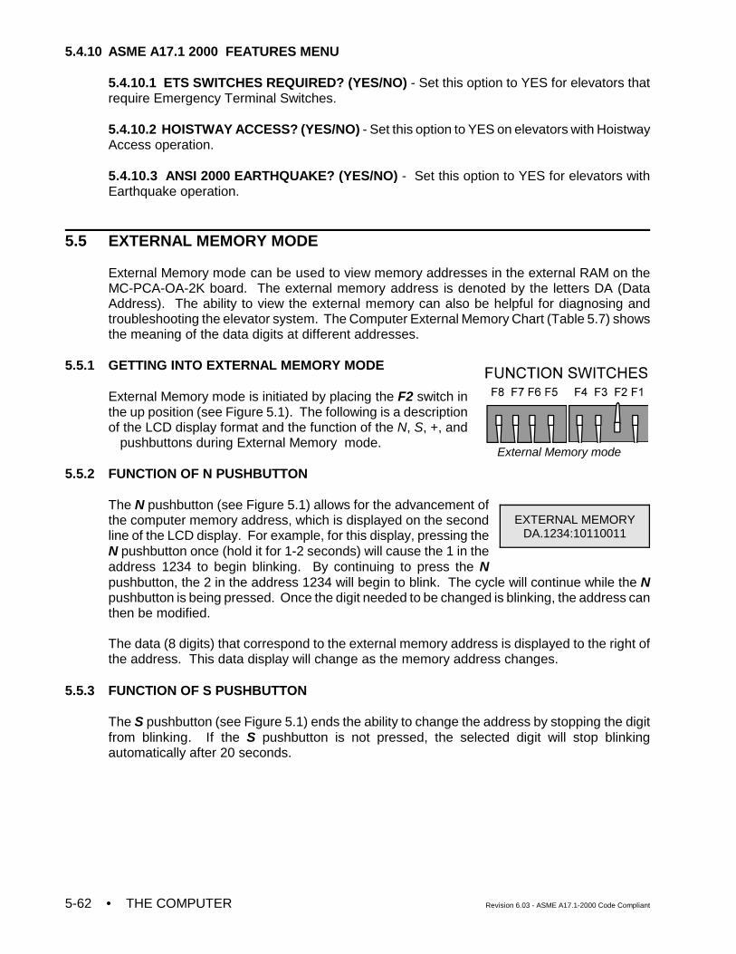
• THE COMPUTER Revision 6.03 - ASME A17.1-2000 Code Compliant5-62
External Memory mode
5.4.10 ASME A17.1 2000 FEATURES MENU
5.4.10.1 ETS SWITCHES REQUIRED? (YES/NO) - Set this option to YES for elevators thatrequire Emergency Terminal Switches.
5.4.10.2 HOISTWAY ACCESS? (YES/NO) - Set this option to YES on elevators with HoistwayAccess operation.
5.4.10.3 ANSI 2000 EARTHQUAKE? (YES/NO) - Set this option to YES for elevators withEarthquake operation.
5.5 EXTERNAL MEMORY MODE
External Memory mode can be used to view memory addresses in the external RAM on theMC-PCA-OA-2K board. The external memory address is denoted by the letters DA (DataAddress). The ability to view the external memory can also be helpful for diagnosing andtroubleshooting the elevator system. The Computer External Memory Chart (Table 5.7) showsthe meaning of the data digits at different addresses.
5.5.1 GETTING INTO EXTERNAL MEMORY MODE
External Memory mode is initiated by placing the F2 switch inthe up position (see Figure 5.1). The following is a descriptionof the LCD display format and the function of the N, S, +, and! pushbuttons during External Memory mode.
5.5.2 FUNCTION OF N PUSHBUTTON
The N pushbutton (see Figure 5.1) allows for the advancement ofthe computer memory address, which is displayed on the secondline of the LCD display. For example, for this display, pressing theN pushbutton once (hold it for 1-2 seconds) will cause the 1 in theaddress 1234 to begin blinking. By continuing to press the Npushbutton, the 2 in the address 1234 will begin to blink. The cycle will continue while the Npushbutton is being pressed. Once the digit needed to be changed is blinking, the address canthen be modified.
The data (8 digits) that correspond to the external memory address is displayed to the right ofthe address. This data display will change as the memory address changes.
5.5.3 FUNCTION OF S PUSHBUTTON
The S pushbutton (see Figure 5.1) ends the ability to change the address by stopping the digitfrom blinking. If the S pushbutton is not pressed, the selected digit will stop blinkingautomatically after 20 seconds.
EXTERNAL MEMORYDA.1234:10110011
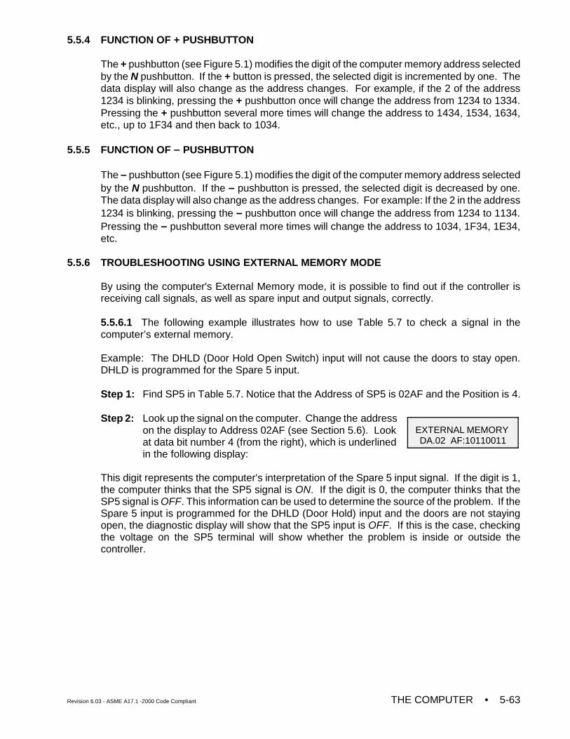
Revision 6.03 - ASME A17.1 -2000 Code Compliant THE COMPUTER • 5-63
EXTERNAL MEMORY DA.02 AF:10110011
5.5.4 FUNCTION OF + PUSHBUTTON
The + pushbutton (see Figure 5.1) modifies the digit of the computer memory address selectedby the N pushbutton. If the + button is pressed, the selected digit is incremented by one. Thedata display will also change as the address changes. For example, if the 2 of the address1234 is blinking, pressing the + pushbutton once will change the address from 1234 to 1334.Pressing the + pushbutton several more times will change the address to 1434, 1534, 1634,etc., up to 1F34 and then back to 1034.
5.5.5 FUNCTION OF – PUSHBUTTON
The – pushbutton (see Figure 5.1) modifies the digit of the computer memory address selectedby the N pushbutton. If the – pushbutton is pressed, the selected digit is decreased by one.The data display will also change as the address changes. For example: If the 2 in the address1234 is blinking, pressing the – pushbutton once will change the address from 1234 to 1134.Pressing the – pushbutton several more times will change the address to 1034, 1F34, 1E34,etc.
5.5.6 TROUBLESHOOTING USING EXTERNAL MEMORY MODE
By using the computer's External Memory mode, it is possible to find out if the controller isreceiving call signals, as well as spare input and output signals, correctly.
5.5.6.1 The following example illustrates how to use Table 5.7 to check a signal in thecomputer’s external memory.
Example: The DHLD (Door Hold Open Switch) input will not cause the doors to stay open.DHLD is programmed for the Spare 5 input.
Step 1: Find SP5 in Table 5.7. Notice that the Address of SP5 is 02AF and the Position is 4.
Step 2: Look up the signal on the computer. Change the addresson the display to Address 02AF (see Section 5.6). Lookat data bit number 4 (from the right), which is underlinedin the following display:
This digit represents the computer's interpretation of the Spare 5 input signal. If the digit is 1,the computer thinks that the SP5 signal is ON. If the digit is 0, the computer thinks that theSP5 signal is OFF. This information can be used to determine the source of the problem. If theSpare 5 input is programmed for the DHLD (Door Hold) input and the doors are not stayingopen, the diagnostic display will show that the SP5 input is OFF. If this is the case, checkingthe voltage on the SP5 terminal will show whether the problem is inside or outside thecontroller.
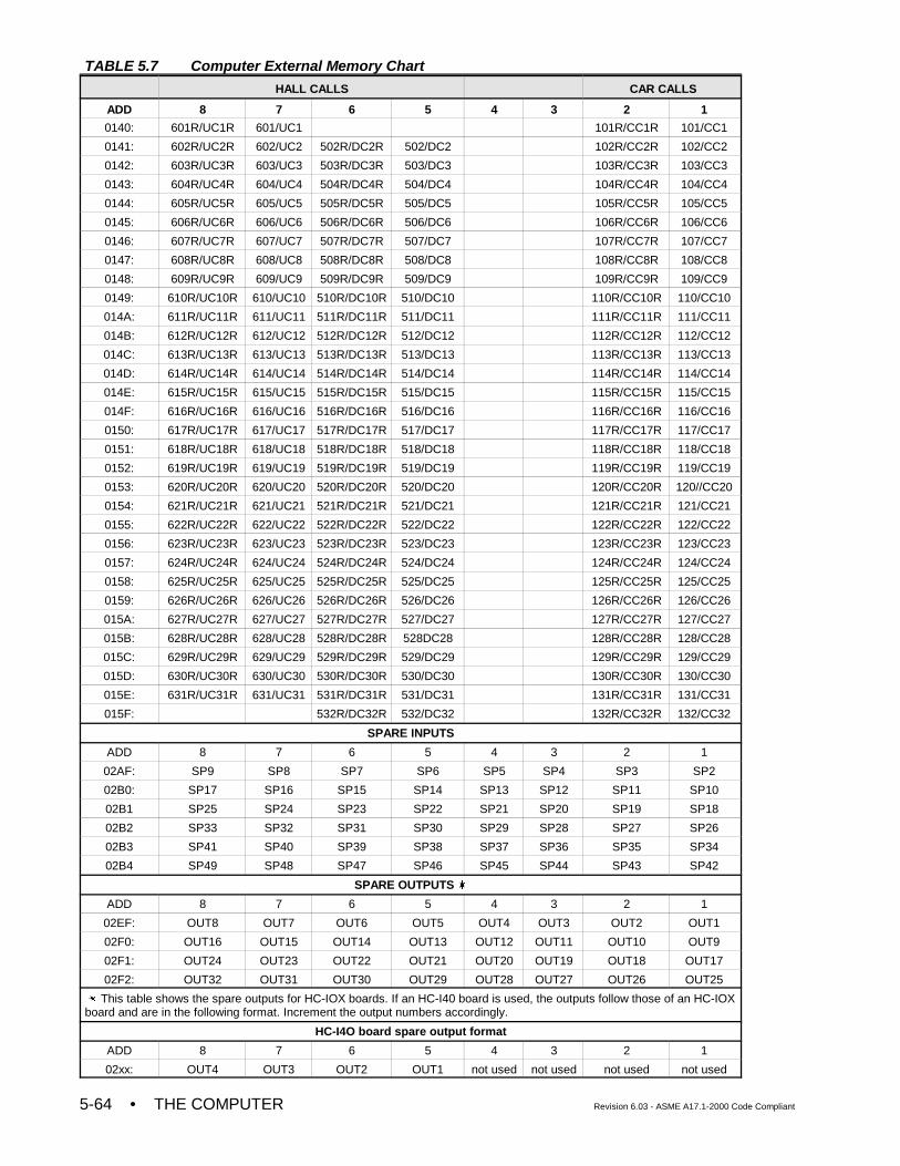
• THE COMPUTER Revision 6.03 - ASME A17.1-2000 Code Compliant5-64
TABLE 5.7 Computer External Memory Chart
HALL CALLS CAR CALLS
ADD 8 7 6 5 4 3 2 1
0140: 601R/UC1R 601/UC1 101R/CC1R 101/CC1
0141: 602R/UC2R 602/UC2 502R/DC2R 502/DC2 102R/CC2R 102/CC2
0142: 603R/UC3R 603/UC3 503R/DC3R 503/DC3 103R/CC3R 103/CC3
0143: 604R/UC4R 604/UC4 504R/DC4R 504/DC4 104R/CC4R 104/CC4
0144: 605R/UC5R 605/UC5 505R/DC5R 505/DC5 105R/CC5R 105/CC5
0145: 606R/UC6R 606/UC6 506R/DC6R 506/DC6 106R/CC6R 106/CC6
0146: 607R/UC7R 607/UC7 507R/DC7R 507/DC7 107R/CC7R 107/CC7
0147: 608R/UC8R 608/UC8 508R/DC8R 508/DC8 108R/CC8R 108/CC8
0148: 609R/UC9R 609/UC9 509R/DC9R 509/DC9 109R/CC9R 109/CC9
0149: 610R/UC10R 610/UC10 510R/DC10R 510/DC10 110R/CC10R 110/CC10
014A: 611R/UC11R 611/UC11 511R/DC11R 511/DC11 111R/CC11R 111/CC11
014B: 612R/UC12R 612/UC12 512R/DC12R 512/DC12 112R/CC12R 112/CC12
014C: 613R/UC13R 613/UC13 513R/DC13R 513/DC13 113R/CC13R 113/CC13
014D: 614R/UC14R 614/UC14 514R/DC14R 514/DC14 114R/CC14R 114/CC14
014E: 615R/UC15R 615/UC15 515R/DC15R 515/DC15 115R/CC15R 115/CC15
014F: 616R/UC16R 616/UC16 516R/DC16R 516/DC16 116R/CC16R 116/CC16
0150: 617R/UC17R 617/UC17 517R/DC17R 517/DC17 117R/CC17R 117/CC17
0151: 618R/UC18R 618/UC18 518R/DC18R 518/DC18 118R/CC18R 118/CC18
0152: 619R/UC19R 619/UC19 519R/DC19R 519/DC19 119R/CC19R 119/CC19
0153: 620R/UC20R 620/UC20 520R/DC20R 520/DC20 120R/CC20R 120//CC20
0154: 621R/UC21R 621/UC21 521R/DC21R 521/DC21 121R/CC21R 121/CC21
0155: 622R/UC22R 622/UC22 522R/DC22R 522/DC22 122R/CC22R 122/CC22
0156: 623R/UC23R 623/UC23 523R/DC23R 523/DC23 123R/CC23R 123/CC23
0157: 624R/UC24R 624/UC24 524R/DC24R 524/DC24 124R/CC24R 124/CC24
0158: 625R/UC25R 625/UC25 525R/DC25R 525/DC25 125R/CC25R 125/CC25
0159: 626R/UC26R 626/UC26 526R/DC26R 526/DC26 126R/CC26R 126/CC26
015A: 627R/UC27R 627/UC27 527R/DC27R 527/DC27 127R/CC27R 127/CC27
015B: 628R/UC28R 628/UC28 528R/DC28R 528DC28 128R/CC28R 128/CC28
015C: 629R/UC29R 629/UC29 529R/DC29R 529/DC29 129R/CC29R 129/CC29
015D: 630R/UC30R 630/UC30 530R/DC30R 530/DC30 130R/CC30R 130/CC30
015E: 631R/UC31R 631/UC31 531R/DC31R 531/DC31 131R/CC31R 131/CC31
015F: 532R/DC32R 532/DC32 132R/CC32R 132/CC32
SPARE INPUTS
ADD 8 7 6 5 4 3 2 1
02AF: SP9 SP8 SP7 SP6 SP5 SP4 SP3 SP2
02B0: SP17 SP16 SP15 SP14 SP13 SP12 SP11 SP10
02B1 SP25 SP24 SP23 SP22 SP21 SP20 SP19 SP18
02B2 SP33 SP32 SP31 SP30 SP29 SP28 SP27 SP26
02B3 SP41 SP40 SP39 SP38 SP37 SP36 SP35 SP34
02B4 SP49 SP48 SP47 SP46 SP45 SP44 SP43 SP42
SPARE OUTPUTS u
ADD 8 7 6 5 4 3 2 1
02EF: OUT8 OUT7 OUT6 OUT5 OUT4 OUT3 OUT2 OUT1
02F0: OUT16 OUT15 OUT14 OUT13 OUT12 OUT11 OUT10 OUT9
02F1: OUT24 OUT23 OUT22 OUT21 OUT20 OUT19 OUT18 OUT17
02F2: OUT32 OUT31 OUT30 OUT29 OUT28 OUT27 OUT26 OUT25
u This table shows the spare outputs for HC-IOX boards. If an HC-I40 board is used, the outputs follow those of an HC-IOXboard and are in the following format. Increment the output numbers accordingly.
HC-I4O board spare output format
ADD 8 7 6 5 4 3 2 1
02xx: OUT4 OUT3 OUT2 OUT1 not used not used not used not used
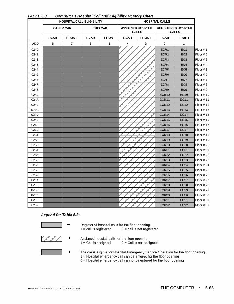
Revision 6.03 - ASME A17.1 -2000 Code Compliant THE COMPUTER • 5-65
TABLE 5.8 Computer’s Hospital Call and Eligibility Memory ChartHOSPITAL CALL ELIGIBILITY HOSPITAL CALLS
OTHER CAR THIS CAR ASSIGNED HOSPITALCALLS
REGISTERED HOSPITALCALLS
REAR FRONT REAR FRONT REAR FRONT REAR FRONT
ADD 8 7 6 5 4 3 2 1
0240: ECR1 EC1 Floor # 1
0241: ECR2 EC2 Floor # 2
0242: ECR3 EC3 Floor # 3
0243: ECR4 EC4 Floor # 4
0244: ECR5 EC5 Floor # 5
0245: ECR6 EC6 Floor # 6
0246: ECR7 EC7 Floor # 7
0247: ECR8 EC8 Floor # 8
0248: ECR9 EC9 Floor # 9
0249: ECR10 EC10 Floor # 10
024A: ECR11 EC11 Floor # 11
024B: ECR12 EC12 Floor # 12
024C: ECR13 EC13 Floor # 13
024D: ECR14 EC14 Floor # 14
024E: ECR15 EC15 Floor # 15
024F: ECR16 EC16 Floor # 16
0250: ECR17 EC17 Floor # 17
0251: ECR18 EC18 Floor # 18
0252: ECR19 EC19 Floor # 19
0253: ECR20 EC20 Floor # 20
0254: ECR21 EC21 Floor # 21
0255: ECR22 EC22 Floor # 22
0256: ECR23 EC23 Floor # 23
0257: ECR24 EC24 Floor # 24
0258: ECR25 EC25 Floor # 25
0259: ECR26 EC26 Floor # 26
025A: ECR27 EC27 Floor # 27
025B: ECR28 EC28 Floor # 28
025C: ECR29 EC29 Floor # 29
025D: ECR30 EC30 Floor # 30
025E: ECR31 EC31 Floor # 31
025F: ECR32 EC32 Floor # 32
Legend for Table 5.8:
! Registered hospital calls for the floor opening. 1 = call is registered 0 = call is not registered
! Assigned hospital calls for the floor opening.1 = Call is assigned 0 = Call is not assigned
! The car is eligible for Hospital Emergency Service Operation for the floor opening.1 = Hospital emergency call can be entered for the floor opening0 = Hospital emergency call cannot be entered for the floor opening
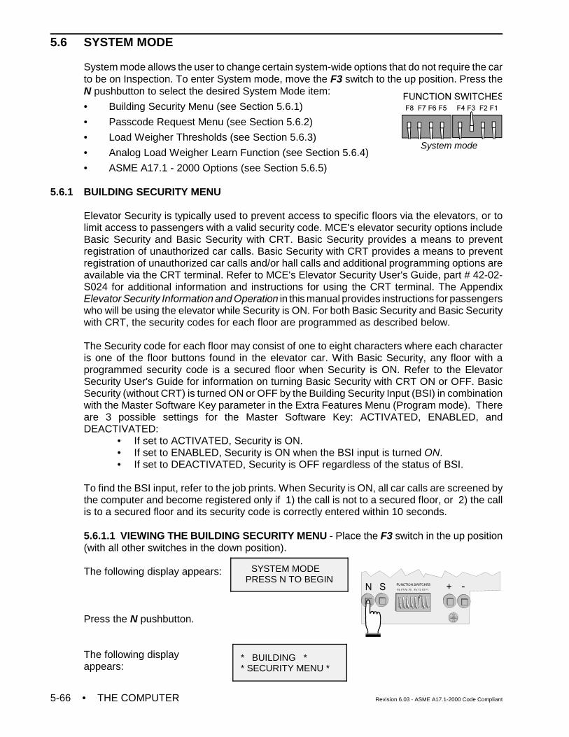
• THE COMPUTER Revision 6.03 - ASME A17.1-2000 Code Compliant5-66
System mode
SYSTEM MODE PRESS N TO BEGIN
* BUILDING ** SECURITY MENU *
5.6 SYSTEM MODE
System mode allows the user to change certain system-wide options that do not require the carto be on Inspection. To enter System mode, move the F3 switch to the up position. Press theN pushbutton to select the desired System Mode item:
• Building Security Menu (see Section 5.6.1)
• Passcode Request Menu (see Section 5.6.2)
• Load Weigher Thresholds (see Section 5.6.3)
• Analog Load Weigher Learn Function (see Section 5.6.4)
• ASME A17.1 - 2000 Options (see Section 5.6.5)
5.6.1 BUILDING SECURITY MENU
Elevator Security is typically used to prevent access to specific floors via the elevators, or tolimit access to passengers with a valid security code. MCE's elevator security options includeBasic Security and Basic Security with CRT. Basic Security provides a means to preventregistration of unauthorized car calls. Basic Security with CRT provides a means to preventregistration of unauthorized car calls and/or hall calls and additional programming options areavailable via the CRT terminal. Refer to MCE's Elevator Security User's Guide, part # 42-02-S024 for additional information and instructions for using the CRT terminal. The AppendixElevator Security Information and Operation in this manual provides instructions for passengerswho will be using the elevator while Security is ON. For both Basic Security and Basic Securitywith CRT, the security codes for each floor are programmed as described below.
The Security code for each floor may consist of one to eight characters where each characteris one of the floor buttons found in the elevator car. With Basic Security, any floor with aprogrammed security code is a secured floor when Security is ON. Refer to the ElevatorSecurity User's Guide for information on turning Basic Security with CRT ON or OFF. BasicSecurity (without CRT) is turned ON or OFF by the Building Security Input (BSI) in combinationwith the Master Software Key parameter in the Extra Features Menu (Program mode). Thereare 3 possible settings for the Master Software Key: ACTIVATED, ENABLED, andDEACTIVATED:
• If set to ACTIVATED, Security is ON. • If set to ENABLED, Security is ON when the BSI input is turned ON. • If set to DEACTIVATED, Security is OFF regardless of the status of BSI.
To find the BSI input, refer to the job prints. When Security is ON, all car calls are screened bythe computer and become registered only if 1) the call is not to a secured floor, or 2) the callis to a secured floor and its security code is correctly entered within 10 seconds.
5.6.1.1 VIEWING THE BUILDING SECURITY MENU - Place the F3 switch in the up position(with all other switches in the down position).
The following display appears:
Press the N pushbutton.
The following displayappears:
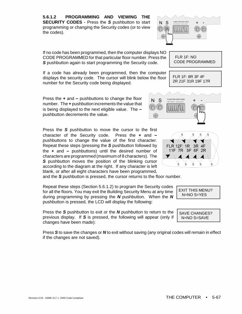
Revision 6.03 - ASME A17.1 -2000 Code Compliant THE COMPUTER • 5-67
FLR 1F: NO CODE PROGRAMMED
FLR 1F: 8R 3F 4F2R 21F 31R 19F 17R
EXIT THIS MENU? N=NO S=YES
SAVE CHANGES? N=NO S=SAVE
5.6.1.2 PROGRAMMING AND VIEWING THESECURITY CODES - Press the S pushbutton to startprogramming or changing the Security codes (or to viewthe codes).
If no code has been programmed, then the computer displays NOCODE PROGRAMMED for that particular floor number. Press theS pushbutton again to start programming the Security code.
If a code has already been programmed, then the computerdisplays the security code. The cursor will blink below the floornumber for the Security code being displayed.
Press the + and – pushbuttons to change the floornumber. The + pushbutton increments the value thatis being displayed to the next eligible value. The –pushbutton decrements the value.
Press the S pushbutton to move the cursor to the firstcharacter of the Security code. Press the + and –pushbuttons to change the value of the first character.Repeat these steps (pressing the S pushbutton followed bythe + and – pushbuttons) until the desired number ofcharacters are programmed (maximum of 8 characters). TheS pushbutton moves the position of the blinking cursoraccording to the diagram at the right. If any character is leftblank, or after all eight characters have been programmed,and the S pushbutton is pressed, the cursor returns to the floor number.
Repeat these steps (Section 5.6.1.2) to program the Security codesfor all the floors. You may exit the Building Security Menu at any timeduring programming by pressing the N pushbutton. When the Npushbutton is pressed, the LCD will display the following:
Press the S pushbutton to exit or the N pushbutton to return to theprevious display. If S is pressed, the following will appear (only ifchanges have been made):
Press S to save the changes or N to exit without saving (any original codes will remain in effectif the changes are not saved).
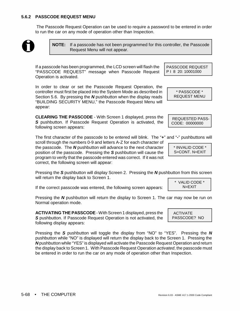
• THE COMPUTER Revision 6.03 - ASME A17.1-2000 Code Compliant5-68
NOTE: If a passcode has not been programmed for this controller, the PasscodeRequest Menu will not appear.
PASSCODE REQUEST P I 8 20: 10001000
* PASSCODE *REQUEST MENU
REQUESTED PASS- CODE: 00000000
* INVALID CODE *S=CONT. N=EXIT
* VALID CODE *N=EXIT
ACTIVATE PASSCODE? NO
5.6.2 PASSCODE REQUEST MENU
The Passcode Request Operation can be used to require a password to be entered in orderto run the car on any mode of operation other than Inspection.
If a passcode has been programmed, the LCD screen will flash the“PASSCODE REQUEST” message when Passcode RequestOperation is activated.
In order to clear or set the Passcode Request Operation, thecontroller must first be placed into the System Mode as described inSection 5.6. By pressing the N pushbutton when the display reads“BUILDING SECURITY MENU,” the Passcode Request Menu willappear:
CLEARING THE PASSCODE - With Screen 1 displayed, press theS pushbutton. If Passcode Request Operation is activated, thefollowing screen appears:
The first character of the passcode to be entered will blink. The “+” and “-” pushbuttons willscroll through the numbers 0-9 and letters A-Z for each character ofthe passcode. The N pushbutton will advance to the next characterposition of the passcode. Pressing the S pushbutton will cause theprogram to verify that the passcode entered was correct. If it was notcorrect, the following screen will appear:
Pressing the S pushbutton will display Screen 2. Pressing the N pushbutton from this screenwill return the display back to Screen 1.
If the correct passcode was entered, the following screen appears:
Pressing the N pushbutton will return the display to Screen 1. The car may now be run onNormal operation mode.
ACTIVATING THE PASSCODE - With Screen 1 displayed, press theS pushbutton. If Passcode Request Operation is not activated, thefollowing display appears:
Pressing the S pushbutton will toggle the display from “NO” to “YES”. Pressing the Npushbutton while “NO” is displayed will return the display back to the Screen 1. Pressing theN pushbutton while “YES” is displayed will activate the Passcode Request Operation and returnthe display back to Screen 1. With Passcode Request Operation activated, the passcode mustbe entered in order to run the car on any mode of operation other than Inspection.
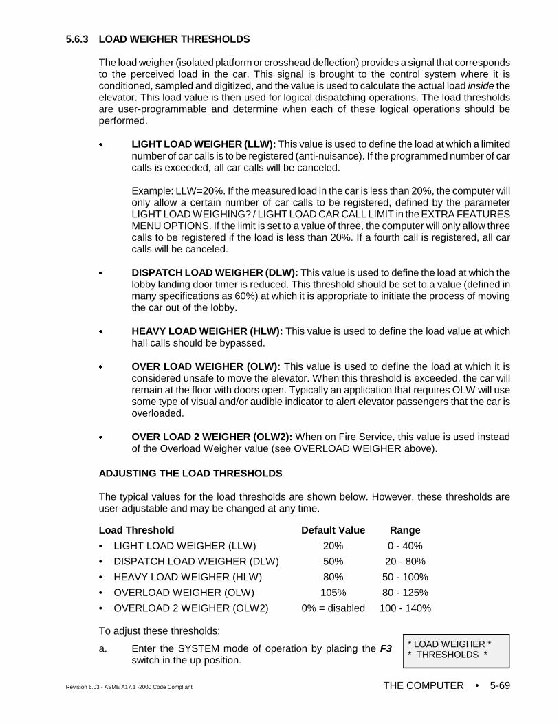
Revision 6.03 - ASME A17.1 -2000 Code Compliant THE COMPUTER • 5-69
* LOAD WEIGHER ** THRESHOLDS *
5.6.3 LOAD WEIGHER THRESHOLDS
The load weigher (isolated platform or crosshead deflection) provides a signal that correspondsto the perceived load in the car. This signal is brought to the control system where it isconditioned, sampled and digitized, and the value is used to calculate the actual load inside theelevator. This load value is then used for logical dispatching operations. The load thresholdsare user-programmable and determine when each of these logical operations should beperformed.
C LIGHT LOAD WEIGHER (LLW): This value is used to define the load at which a limitednumber of car calls is to be registered (anti-nuisance). If the programmed number of carcalls is exceeded, all car calls will be canceled.
Example: LLW=20%. If the measured load in the car is less than 20%, the computer willonly allow a certain number of car calls to be registered, defined by the parameterLIGHT LOAD WEIGHING? / LIGHT LOAD CAR CALL LIMIT in the EXTRA FEATURESMENU OPTIONS. If the limit is set to a value of three, the computer will only allow threecalls to be registered if the load is less than 20%. If a fourth call is registered, all carcalls will be canceled.
C DISPATCH LOAD WEIGHER (DLW): This value is used to define the load at which thelobby landing door timer is reduced. This threshold should be set to a value (defined inmany specifications as 60%) at which it is appropriate to initiate the process of movingthe car out of the lobby.
C HEAVY LOAD WEIGHER (HLW): This value is used to define the load value at whichhall calls should be bypassed.
C OVER LOAD WEIGHER (OLW): This value is used to define the load at which it isconsidered unsafe to move the elevator. When this threshold is exceeded, the car willremain at the floor with doors open. Typically an application that requires OLW will usesome type of visual and/or audible indicator to alert elevator passengers that the car isoverloaded.
C OVER LOAD 2 WEIGHER (OLW2): When on Fire Service, this value is used insteadof the Overload Weigher value (see OVERLOAD WEIGHER above).
ADJUSTING THE LOAD THRESHOLDS
The typical values for the load thresholds are shown below. However, these thresholds areuser-adjustable and may be changed at any time.
Load Threshold Default Value Range
• LIGHT LOAD WEIGHER (LLW) 20% 0 - 40%
• DISPATCH LOAD WEIGHER (DLW) 50% 20 - 80%
• HEAVY LOAD WEIGHER (HLW) 80% 50 - 100%
• OVERLOAD WEIGHER (OLW) 105% 80 - 125%
• OVERLOAD 2 WEIGHER (OLW2) 0% = disabled 100 - 140%
To adjust these thresholds:
a. Enter the SYSTEM mode of operation by placing the F3switch in the up position.
• THE COMPUTER Revision 6.03 - ASME A17.1-2000 Code Compliant5-70
LIGHT LOADWEIGHER = 20%
ANALOG LOAD WEIGHPRESS S TO START
b. Press the N pushbutton until LOAD WEIGHERTHRESHOLDS appears on the LCD display.
c. Press the S pushbutton to display the load threshold youwish to set.
d. The value shown is the current threshold value expressed as a percentage of the fullload value (see the table above). Press the '+' or '-' pushbutton to adjust the value. If thevalue is set to 0%, the load weigher function is disabled.
e. Press the S pushbutton to select another load threshold to adjust or press the Npushbutton to exit this menu.
f. Place the F3 switch in the down position to exit SYSTEM mode when finished.
If an analog load weigher is used, the Analog Load Weigher Learn Function must be performedbefore the load weigher system will perform properly (see Section 5.6.4).
5.6.4 ANALOG LOAD WEIGHER LEARN FUNCTION
With the isolated platform load weigher (MCE), the system simply learns the reference valuesof the empty and fully loaded car weight. However, with the crosshead deflection load weigher(K-Tech), the system must learn the reference values at each floor due to the dynamics of theelevator system. This is necessary because the perceived load at the crosshead varies with theposition of the car in the hoistway due to the changing proportion of the traveling cable hangingbeneath the car and the position of the compensation cables.
The Analog Load Weigher Learn Function is performed as follows:
a. Move the empty car to a convenient floor where the test weights are located. It is bestto have one person in the machine room and another person at the floor to load theweights.
b. Place the car on Independent Service operation. If an Independent Service switch is notavailable in the car, place a jumper between panel mount terminal 2 and terminal 49 onthe Main Relay board (SC-SB2K).
c. Place the F3 switch in the up position and press the Npushbutton to select the Analog Load Weigher LearnFunction (scrolling message is displayed).
d. Press the S pushbutton to start. The computer responds with one of two scrollingmessages:
• CAR NOT READY TO LEARN, MUST BE ON INDEPENDENT SERVICE.
Verify that the car has been placed on Independent Service.
• READY TO LEARN EMPTY CAR VALUES? PRESS S TO START.
If the empty car values have already been learned and you want to be learn the full carvalues, press the N pushbutton (go to step 'e').
To begin learning the empty car values, press the S pushbutton. The computer displaysthe message:
• LEARNING EMPTY CAR VALUES. PRESS N TO ABORT.
Revision 6.03 - ASME A17.1 -2000 Code Compliant THE COMPUTER • 5-71
CURRENT LOAD= 100%
CURRENT LOAD= NOT LEARNED
If the Extra Features Menu Option “Analog Load Weigher?” is set to K-TECH, the carwill move to the bottom floor, record the empty car value and then move up, stoppingat each floor to record the empty car value. When the top floor has been reached, thecar will move back to the floor at which the Analog Load Weigher Learn Function wasbegun and the computer will display the scrolling message:
• EMPTY CAR LEARN PROCESS COMPLETED. PRESS S TO CONT.
If the Extra Features Menu Option “Analog Load Weigher?” is set to MCE, the car willlearn the empty car value and then display the message:
• EMPTY CAR LEARN PROCESS COMPLETED. PRESS S TO CONT.
Press the S pushbutton.
e. The computer displays the scrolling message:
• READY TO LEARN FULL CAR VALUES? PRESS S TO START.
f. Place the full load test weights in the car and press the S pushbutton to begin learningthe full car values. The computer displays the message:
• LEARNING FULL CAR VALUES. PRESS N TO ABORT.
If the Extra Features Menu Option “Analog Load Weigher?” is set to K-TECH, the carwill move to the bottom floor, record the full car value and then move up, stopping ateach floor to record the full car value. When the top floor has been reached, the car willmove back to the floor at which the Analog Load Weigher Learn Function was begunand the computer will display the scrolling message:
• FULL CAR LEARN PROCESS COMPLETED. PRESS S TO CONT.
If the Extra Features Menu Option “Analog Load Weigher?” is set to MCE, the car willlearn the full car value and then display the message:
• FULL CAR LEARN PROCESS COMPLETED. PRESS S TO CONT.
Press the S pushbutton, place the F3 switch in the down position and take the car offof Independent service.
g. To verify that the Load Weigher Learn Function has beenperformed successfully, place the F8 switch in the upposition. With the test weights in the car, the followingshould be displayed:
If the Load Weigher Learn Function has not beenperformed successfully, the following will be displayed:
h. The Load Weigher Learn Function (empty or full values) may be aborted at any time bypressing the N pushbutton. The computer will display the message:
• LEARN PROCESS ABORTED... PRESS S TO CONT.
When the S pushbutton is pressed the computer displays the scrolling message:
• ANALOG LOAD WEIGHER LEARN FUNCTION. PRESS S TO START
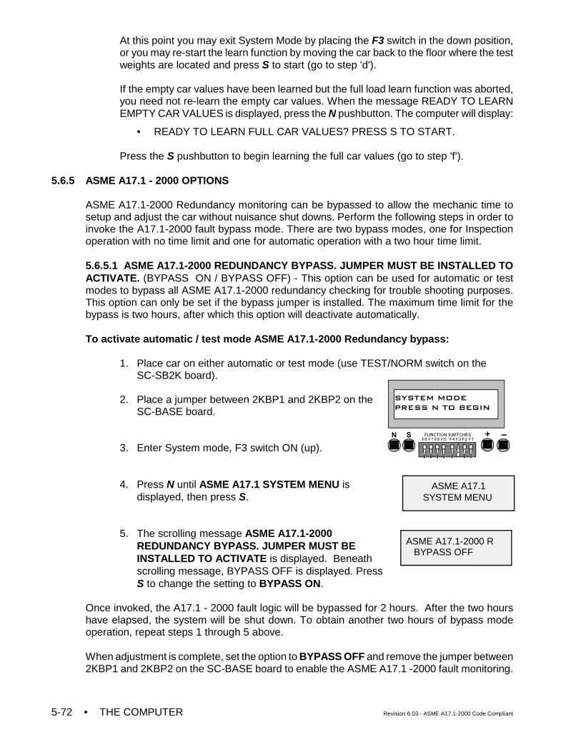
• THE COMPUTER Revision 6.03 - ASME A17.1-2000 Code Compliant5-72
ASME A17.1 SYSTEM MENU
ASME A17.1-2000 R BYPASS OFF
At this point you may exit System Mode by placing the F3 switch in the down position,or you may re-start the learn function by moving the car back to the floor where the testweights are located and press S to start (go to step 'd').
If the empty car values have been learned but the full load learn function was aborted,you need not re-learn the empty car values. When the message READY TO LEARNEMPTY CAR VALUES is displayed, press the N pushbutton. The computer will display:
• READY TO LEARN FULL CAR VALUES? PRESS S TO START.
Press the S pushbutton to begin learning the full car values (go to step 'f').
5.6.5 ASME A17.1 - 2000 OPTIONS
ASME A17.1-2000 Redundancy monitoring can be bypassed to allow the mechanic time tosetup and adjust the car without nuisance shut downs. Perform the following steps in order toinvoke the A17.1-2000 fault bypass mode. There are two bypass modes, one for Inspectionoperation with no time limit and one for automatic operation with a two hour time limit.
5.6.5.1 ASME A17.1-2000 REDUNDANCY BYPASS. JUMPER MUST BE INSTALLED TOACTIVATE. (BYPASS ON / BYPASS OFF) - This option can be used for automatic or testmodes to bypass all ASME A17.1-2000 redundancy checking for trouble shooting purposes.This option can only be set if the bypass jumper is installed. The maximum time limit for thebypass is two hours, after which this option will deactivate automatically.
To activate automatic / test mode ASME A17.1-2000 Redundancy bypass:
1. Place car on either automatic or test mode (use TEST/NORM switch on theSC-SB2K board).
2. Place a jumper between 2KBP1 and 2KBP2 on theSC-BASE board.
3. Enter System mode, F3 switch ON (up).
4. Press N until ASME A17.1 SYSTEM MENU isdisplayed, then press S.
5. The scrolling message ASME A17.1-2000REDUNDANCY BYPASS. JUMPER MUST BEINSTALLED TO ACTIVATE is displayed. Beneathscrolling message, BYPASS OFF is displayed. PressS to change the setting to BYPASS ON.
Once invoked, the A17.1 - 2000 fault logic will be bypassed for 2 hours. After the two hourshave elapsed, the system will be shut down. To obtain another two hours of bypass modeoperation, repeat steps 1 through 5 above.
When adjustment is complete, set the option to BYPASS OFF and remove the jumper between2KBP1 and 2KBP2 on the SC-BASE board to enable the ASME A17.1 -2000 fault monitoring.
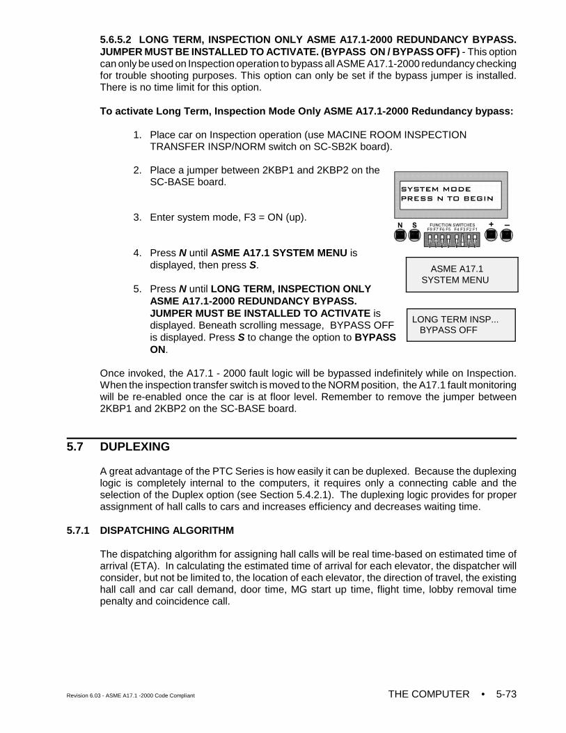
Revision 6.03 - ASME A17.1 -2000 Code Compliant THE COMPUTER • 5-73
ASME A17.1 SYSTEM MENU
LONG TERM INSP... BYPASS OFF
5.6.5.2 LONG TERM, INSPECTION ONLY ASME A17.1-2000 REDUNDANCY BYPASS.JUMPER MUST BE INSTALLED TO ACTIVATE. (BYPASS ON / BYPASS OFF) - This optioncan only be used on Inspection operation to bypass all ASME A17.1-2000 redundancy checkingfor trouble shooting purposes. This option can only be set if the bypass jumper is installed.There is no time limit for this option.
To activate Long Term, Inspection Mode Only ASME A17.1-2000 Redundancy bypass:
1. Place car on Inspection operation (use MACINE ROOM INSPECTIONTRANSFER INSP/NORM switch on SC-SB2K board).
2. Place a jumper between 2KBP1 and 2KBP2 on theSC-BASE board.
3. Enter system mode, F3 = ON (up).
4. Press N until ASME A17.1 SYSTEM MENU isdisplayed, then press S.
5. Press N until LONG TERM, INSPECTION ONLYASME A17.1-2000 REDUNDANCY BYPASS.JUMPER MUST BE INSTALLED TO ACTIVATE isdisplayed. Beneath scrolling message, BYPASS OFFis displayed. Press S to change the option to BYPASSON.
Once invoked, the A17.1 - 2000 fault logic will be bypassed indefinitely while on Inspection.When the inspection transfer switch is moved to the NORM position, the A17.1 fault monitoringwill be re-enabled once the car is at floor level. Remember to remove the jumper between2KBP1 and 2KBP2 on the SC-BASE board.
5.7 DUPLEXING
A great advantage of the PTC Series is how easily it can be duplexed. Because the duplexinglogic is completely internal to the computers, it requires only a connecting cable and theselection of the Duplex option (see Section 5.4.2.1). The duplexing logic provides for properassignment of hall calls to cars and increases efficiency and decreases waiting time.
5.7.1 DISPATCHING ALGORITHM
The dispatching algorithm for assigning hall calls will be real time-based on estimated time ofarrival (ETA). In calculating the estimated time of arrival for each elevator, the dispatcher willconsider, but not be limited to, the location of each elevator, the direction of travel, the existinghall call and car call demand, door time, MG start up time, flight time, lobby removal timepenalty and coincidence call.
• THE COMPUTER Revision 6.03 - ASME A17.1-2000 Code Compliant5-74
5.7.2 HARDWARE CONNECTIONS
There are two critical items in duplexing hardware: Proper grounding between the twocontroller subplates and proper installation of the duplexing cable. The hall calls will beconnected to both cars simultaneously. Once in a duplex configuration, either of the twocontrollers can become the dispatcher of hall calls. The controller that assumes the dispatchingduty on power up remains the dispatching processor until it is taken out of service. If, for anyreason, the communication link between the two controllers does not function, each car willrespond to the registered hall calls independently.
5.7.3 TROUBLESHOOTING
In a duplexing configuration, the controller that assumes dispatching duty is identified by theletter D in the upper left corner of the LCD display. The other car is identified by the letter S(slave), in the upper left corner of the LCD. If the upper left-hand corner of the LCD is blank(neither the D nor the S is displayed), the cars are not communicating, the followingtroubleshooting steps should be taken:
Step 1: Check for proper grounding between the two subplates.
Step 2: Check the communication cable hook-up.
Step 3: The JP3 jumper is installed on both MC-PCA-OA-2K boards (found next to thepower supply terminals, see Figure 5.1) as the default configuration for duplexcommunication. JP3 is an EIA-485 Standard Communication Termination jumper.However, in an attempt to optimize the duplex communication, the JP3 jumper maybe removed from either one or both of the MC-PCA-0A-2K boards.
Step 4: If all of the above are unsuccessful, contact MCE.
If the D and/or S indicators on the LCD are flickering, it is most likely caused by badcommunication and the following troubleshooting steps should be taken:
Step 1: Check the Communication Time-Out Error Counter shown in Table 5.4 (Address42). If the counter is actively counting errors, the slave computer is notresponding to the dispatcher's request for information. If the cause is acommunication problem, complete Steps 1-4 above.
Step 2: Check the Communication Checksum Error Counter shown in Table 5.4(Address 43). If the counter is actively counting errors, the data being receivedis bad or does not have integrity and cannot be used by the computer. If thecause is a communication problem, complete Steps 1-4 above.
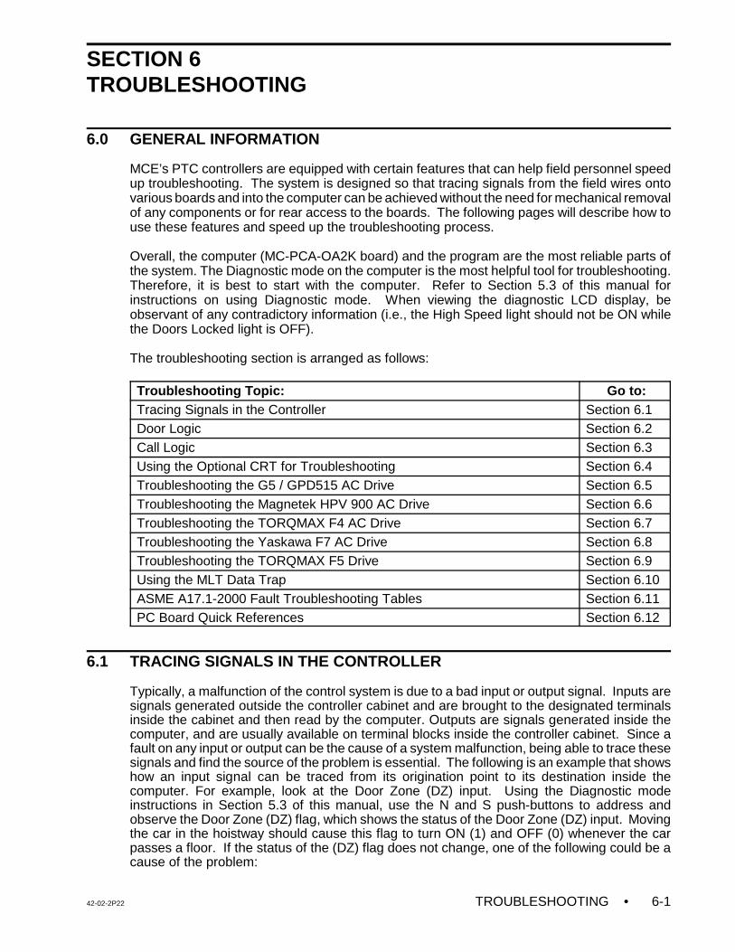
42-02-2P22 TROUBLESHOOTING • 6-1
SECTION 6TROUBLESHOOTING
6.0 GENERAL INFORMATION
MCE’s PTC controllers are equipped with certain features that can help field personnel speedup troubleshooting. The system is designed so that tracing signals from the field wires ontovarious boards and into the computer can be achieved without the need for mechanical removalof any components or for rear access to the boards. The following pages will describe how touse these features and speed up the troubleshooting process.
Overall, the computer (MC-PCA-OA2K board) and the program are the most reliable parts ofthe system. The Diagnostic mode on the computer is the most helpful tool for troubleshooting.Therefore, it is best to start with the computer. Refer to Section 5.3 of this manual forinstructions on using Diagnostic mode. When viewing the diagnostic LCD display, beobservant of any contradictory information (i.e., the High Speed light should not be ON whilethe Doors Locked light is OFF).
The troubleshooting section is arranged as follows:
Troubleshooting Topic: Go to:Tracing Signals in the Controller Section 6.1Door Logic Section 6.2Call Logic Section 6.3Using the Optional CRT for Troubleshooting Section 6.4Troubleshooting the G5 / GPD515 AC Drive Section 6.5Troubleshooting the Magnetek HPV 900 AC Drive Section 6.6Troubleshooting the TORQMAX F4 AC Drive Section 6.7Troubleshooting the Yaskawa F7 AC Drive Section 6.8Troubleshooting the TORQMAX F5 Drive Section 6.9Using the MLT Data Trap Section 6.10ASME A17.1-2000 Fault Troubleshooting Tables Section 6.11PC Board Quick References Section 6.12
6.1 TRACING SIGNALS IN THE CONTROLLER
Typically, a malfunction of the control system is due to a bad input or output signal. Inputs aresignals generated outside the controller cabinet and are brought to the designated terminalsinside the cabinet and then read by the computer. Outputs are signals generated inside thecomputer, and are usually available on terminal blocks inside the controller cabinet. Since afault on any input or output can be the cause of a system malfunction, being able to trace thesesignals and find the source of the problem is essential. The following is an example that showshow an input signal can be traced from its origination point to its destination inside thecomputer. For example, look at the Door Zone (DZ) input. Using the Diagnostic modeinstructions in Section 5.3 of this manual, use the N and S push-buttons to address andobserve the Door Zone (DZ) flag, which shows the status of the Door Zone (DZ) input. Movingthe car in the hoistway should cause this flag to turn ON (1) and OFF (0) whenever the carpasses a floor. If the status of the (DZ) flag does not change, one of the following could be acause of the problem:
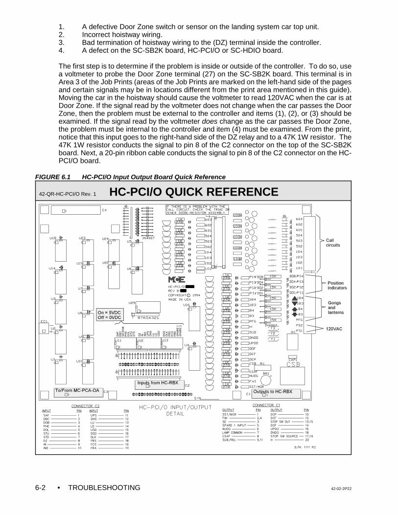
• TROUBLESHOOTING 42-02-2P226-2
1. A defective Door Zone switch or sensor on the landing system car top unit.2. Incorrect hoistway wiring. 3. Bad termination of hoistway wiring to the (DZ) terminal inside the controller.4. A defect on the SC-SB2K board, HC-PCI/O or SC-HDIO board.
The first step is to determine if the problem is inside or outside of the controller. To do so, usea voltmeter to probe the Door Zone terminal (27) on the SC-SB2K board. This terminal is inArea 3 of the Job Prints (areas of the Job Prints are marked on the left-hand side of the pagesand certain signals may be in locations different from the print area mentioned in this guide).Moving the car in the hoistway should cause the voltmeter to read 120VAC when the car is atDoor Zone. If the signal read by the voltmeter does not change when the car passes the DoorZone, then the problem must be external to the controller and items (1), (2), or (3) should beexamined. If the signal read by the voltmeter does change as the car passes the Door Zone,the problem must be internal to the controller and item (4) must be examined. From the print,notice that this input goes to the right-hand side of the DZ relay and to a 47K 1W resistor. The47K 1W resistor conducts the signal to pin 8 of the C2 connector on the top of the SC-SB2Kboard. Next, a 20-pin ribbon cable conducts the signal to pin 8 of the C2 connector on the HC-PCI/O board.
FIGURE 6.1 HC-PCI/O Input Output Board Quick Reference
42-QR-HC-PCI/O Rev. 1 HC-PCI/O QUICK REFERENCE
42-02-2P22 TROUBLESHOOTING • 6-3
Figure 6.1 is a picture of the HC-PCI/O board, which shows where the DZ signal can be foundon this board. Refer to the SC-SB2K board illustration in Section 1 for the location of the DZsignal on the Relay board. If power is present at terminal 27, there should be approximately120VAC at the bottom of the 47K 1W resistor corresponding to DZ. Whereas the top of thesame resistor should read approximately 5VAC if the C2 ribbon cable is connected. If theribbon cable is disconnected, the reading should be 120VAC at the top of this same resistor.This is because the other half of the voltage divider is on the HC-PCI/O board.
The SC-SB2K board has test pins near many of the relays. These pins are for use during theinspection and testing of section 4. Use the controller wiring diagrams to locate the test pins.Pins on the left of relay coils (as depicted in the schematics) would need to be connected toTP1 (fused 1-bus) to energize the associated relay. Pins located on the right hand side of thecoil would be connected to TP2 (fused 2-bus , 120 VAC) to allow the relays to pick. Somerelays require both test points (TP1 and TP2) to allow the coil to energize. Relays that do nothave associated test pins can be readily energized via the terminals connected to the coils (likeCHDT, use screw terminal 9).
It is therefore not necessary to remove the SC-SB2K board to check the operation of the relays.The signals can also be traced on the HC-PCI/O board. See Figure 6.1 for details. If the signalgets to the HC-PCI/O board but does not get to the computer, it would be safe to assume thatthe problem is on the HC-PCI/O board.
6.2 DOOR LOGIC
As complex as it is, the Door Logic portion of the software answers one simple question:Should the doors be open? The computer looks at certain inputs and then calls upon specificlogic to determine the answer to this basic question. All of these inputs and all of the flagsgenerated by the specific logic are available for viewing through Diagnostic mode on thecomputer. When troubleshooting a door problem, inspecting the action and sequence of theseflags and inputs is very important. When the meaning of the flags becomes more familiar, thestate of these flags will generally serve to point to the root of the problem. Once the computerhas determined the answer to the door status question, the appropriate outputs are turned ONand/or OFF to attempt to cause the doors to be in the desired state.
The computer looks at the following inputs:
DBC - Door Close Button InputDCLC - Door Closed Contacts Input (Retiring Cam only)DLK - Door Locks InputDOB - Door Open Button InputDOL - Door Open Limit InputDZ - Door Zone InputPHE - Photo Eye Input SE - Safety Edge Input
The computer generates the following outputs:
DCF - Door Close Function OutputDCP - Door Close Power OutputDOF - Door Open Function Output
• TROUBLESHOOTING 42-02-2P226-4
Associated important computer-generated logic flags:
CCT - Car Call Time FlagDOI - Door Open Intent FlagDSH - Door Shortening (Intermediate) FlagDSHT - Door Shortening (Final) FlagHCT - Hall Call Time FlagLOT - Lobby Call Time FlagSDT - Short Door Time Flag
The computer uses the flags and inputs listed above to make a decision concerning the desiredstate of the doors. This decision has only two possible goals: doors open or doors closed.The computer's answer to this question is reflected in the state of the Door Open Intent (DOI)flag. If the computer recognizes a valid reason either to open the doors or keep the doorsopen, it will set (turn ON) this internal flag. This flag can be seen by using Diagnostic mode onthe computer. When inspecting this flag using Diagnostic mode, notice that the DOI flag turnsON (1) when the computer decides that the doors should be open. If the computer decides thatthe doors should be closed, the DOI flag will be turned OFF (0).
The DOI flag is a useful flag to inspect when troubleshooting door problems. This flag showsthe intention of the computer concerning the state of the doors.
Remember that if the DOI flag is ON (1), it will turn on the DOF output which should pick theDO relay. The door will remain open until the DOL (Door Open Limit) input goes away. Thiswill shut OFF the DOF output while the doors are open and DOI is ON. Turning OFF the DOIflag will turn ON the DCF output, which will pick the DC relay and close the doors. While thereis no demand to go anywhere, the signal that shuts OFF the DCF output is DLK (DoorsLocked), or possibly DCLC if the car has a retiring cam. However, there is a 2-second delaybefore the DCF output turns OFF after the doors are locked. If there is any demand (as isevidenced by the DMU or DMD flags being ON) and if the DOI flag is not ON (0), then the DCPoutput will be turned ON regardless of the position of the door. The DCP output is used toprovide door closing power for those door operators requiring power while the car is running,such as those made by G.A.L. Corporation.
The various values of door standing open time result from the type of call canceled orresponded to. A hall call cancellation will give an HCT flag and a car call cancellation will givea CCT flag. A door reopen from a hall or car call button at the lobby, or a lobby hall or car callcancellation will give a LOT flag. A door reopen from the Photo Eye, Safety Edge or DoorOpen button will give a SDT flag. Each flag (HCT, CCT, LOT, or SDT) has a separate doorstanding open time.
The door logic provides protection timers for the door equipment both in the open and the closedirection. If the doors get stuck because of the door interlock keeper failing to lift high enoughto clear the door interlock during the opening cycle, then the doors cannot complete theiropening cycle. This could result in damage to the door motor. The door open protection timerwill eventually stop trying to open the doors so the car can go on to the next call. Similarly, ifthe doors do not close all the way (i.e., the doors do not lock), the computer will recycle thedoors at a programmed interval in an attempt to clear the problem.
To provide a clearer understanding of the computer logic, note that the logic looks for a reasonto open the doors. If a valid reason to open the doors is not found, or if conditions are detectedthat prohibit the opening of the doors, the logic will close the doors (reset or turn OFF DOI).To open the doors, the car must be in a door zone and not running at high or intermediate
42-02-2P22 TROUBLESHOOTING • 6-5
speed. Once the car has settled into a proper position to open the doors, a condition must existthat says to the logic that the doors should be open.
Some of these conditions are listed below:
• Call demand at the current landing (or a call has just been canceled)• Safety Edge/Door Open button (DOB) input• Emergency/Independent Service conditions • Photo Eye input
When a call is canceled, one of the following door time flags should be set (turned ON): CCT,HCT, or LOT. When one of the reopening devices is active (SE, PHE, or DOB), the SDT flagshould be set. When an Emergency or Independent Service condition exists, the presence ofa particular condition will cause the DOI flag to be set. Some of these conditions include thefollowing: Fire Service, Emergency Power operation, Independent Service, Attendant Service,etc.
Once the intention of the computer has been determined, inspect the high voltage hardwareto see if the appropriate functions are being carried out. For example, if the doors are closedand DOI is set, the doors should be opening (the DO relay picked). If the doors are open andDOI is cleared (turned OFF), the doors should be closing (the DC relay picked).
The trouble arises when the door control system is not doing what the mechanic thinks it shouldbe doing. However, when troubleshooting, it is vital to determine if the control system is doingwhat it thinks it should be doing. If the control system (high voltage section) is doing what thelogic intends it to do, then determining how the logic is coming to its conclusions is important.If the control system is not doing what the logic intends it to do, then determining what ispreventing the desired function from being carried out is important (bad relay, bad triac, etc.).Diagnostic mode on the MC-PCA-OA2K Computer board will help to determine which situationis present. The output flags will show which outputs the computer is attempting to turn ON orOFF. These flags can be compared with what is actually happening in the high voltagehardware.
Consider, as an example, this problem: the doors are closed and locked on the car, but the DCrelay is always picked, preventing the doors from opening when they should. The cause of theproblem must first be isolated. If both the DCF and DCP flags are cleared (turned OFF) in thecomputer, the DC relay should not be picked. If the DC relay is picked, then a problemobviously exists in the output string to the DC relay. However, if either the DCF or DCP flagis always set in the computer, then the problem is not with the output circuit, but possibly aproblem with the door lock circuitry. If the doors are truly physically locked, inspecting the DLKflag in the computer would be wise. If the flag is not set in the computer, then there is obviouslya fault in the input circuit from the door lock input. A simple inspection of the computer'sDiagnostic mode will substantially narrow down the cause of the problem.
Refer to Figure 6.2 Door Sequence of Operation, Figure 6.3 Door Closing Sequence, Timingand Fault Generation and Figure 6.4 Door Operation Timing Diagram.
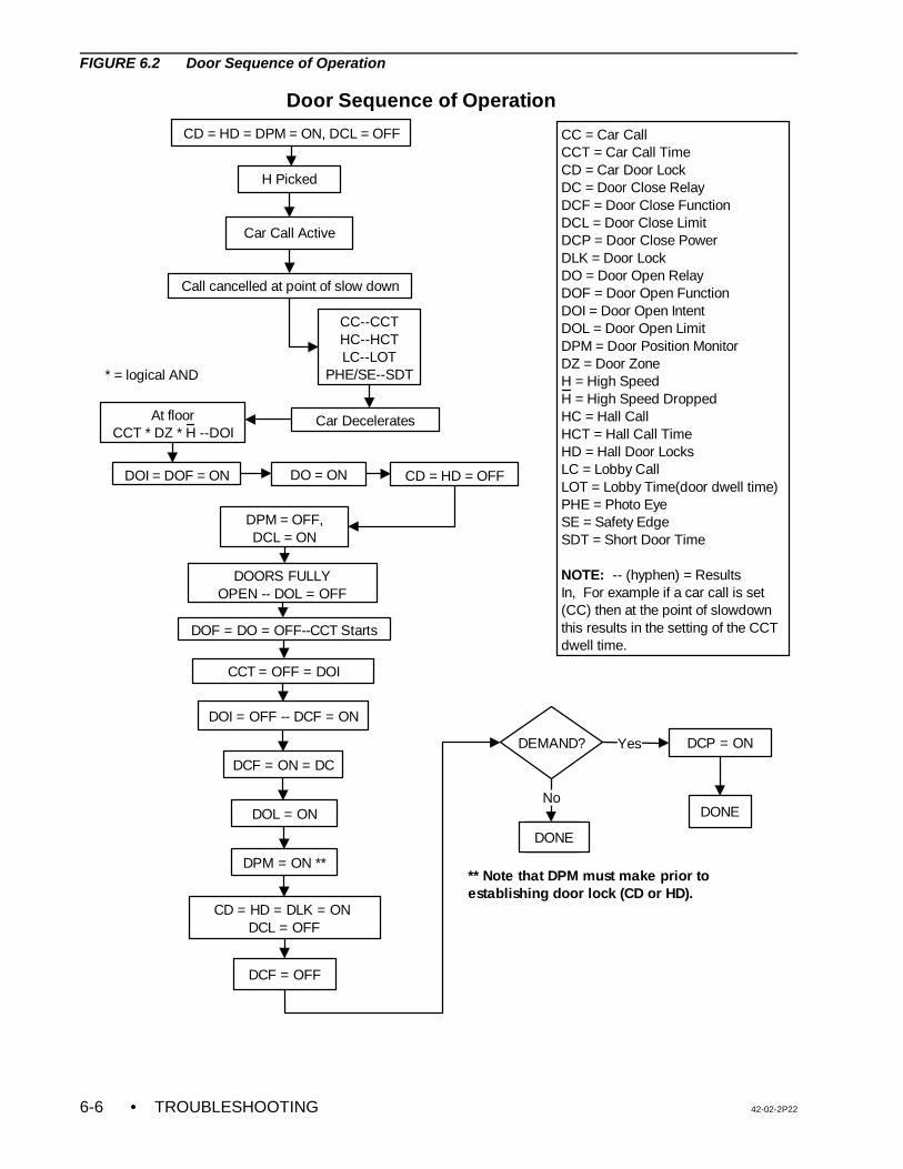
• TROUBLESHOOTING 42-02-2P226-6
H Picked
Car Call Active
Call cancelled at point of slow down
CC--CCTHC--HCTLC--LOT
PHE/SE--SDT
Car DeceleratesAt floorCCT * DZ * H --DOI
DOI = DOF = ON
DOF = DO = OFF--CCT Starts
CCT = OFF = DOI
DEMAND?
DONE
DOI = OFF -- DCF = ON
DCF = ON = DC
CD = HD = DLK = ON DCL = OFF
DCF = OFF
DCP = ON
DONE
CC = Car CallCCT = Car Call TimeCD = Car Door LockDC = Door Close RelayDCF = Door Close FunctionDCL = Door Close LimitDCP = Door Close PowerDLK = Door LockDO = Door Open RelayDOF = Door Open FunctionDOI = Door Open IntentDOL = Door Open LimitDPM = Door Position MonitorDZ = Door ZoneH = High SpeedH = High Speed DroppedHC = Hall CallHCT = Hall Call TimeHD = Hall Door LocksLC = Lobby CallLOT = Lobby Time(door dwell time)PHE = Photo EyeSE = Safety EdgeSDT = Short Door Time
NOTE: -- (hyphen) = Results In, For example if a car call is set (CC) then at the point of slowdown this results in the setting of the CCT dwell time.
CD = HD = DPM = ON, DCL = OFF
CD = HD = OFFDO = ON
DPM = OFF,DCL = ON
DOORS FULLY OPEN -- DOL = OFF
** Note that DPM must make prior to establishing door lock (CD or HD).
Door Sequence of Operation
DPM = ON **
Yes
* = logical AND
DONE
NoDOL = ON
FIGURE 6.2 Door Sequence of Operation
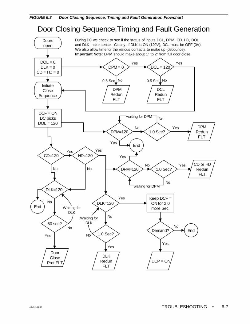
42-02-2P22 TROUBLESHOOTING • 6-7
Door Closing Sequence,Timing and Fault Generation
Doors open
DOL = 0DLK = 0
CD = HD = 0DPM = 0 DCL = 120
DPM Redun FLT
No
Yes
DCL Redun FLT
NoInitiate Close
Sequence
DCF = ONDC picks
DOL = 120
Yes
DLK=120
60 sec?
Door Close
Prot FLT
No
Yes
CD=120
DPM=120 1.0 Sec?No Yes
Keep DCF = ON for 2.0 more Sec.
Demand?
DCP = ON
EndNo
Yes
During DC we check to see if the status of inputs DCL, DPM, CD, HD, DOLand DLK make sense. Clearly, if DLK is ON (120V), DCL must be OFF (0V). We also allow time for the various contacts to make up (debounce). Important Note: DPM should make about 1" to 2" from full door close.
HD=120Yes
1.0 Sec?
DLK Redun FLT
No
Yes
NoDLK=120
No No
No
0.5 Sec 0.5 Sec
YesEnd
Yes
DPM=120 1.0 Sec?DPM
Redun FLT
No
No
Yes
Yes
No
Yes
No
waiting for DPM
waiting for DPM
Waiting forDLK
Waiting forDLK
End
CD or HD Redun FLT
FIGURE 6.3 Door Closing Sequence, Timing and Fault Generation Flowchart
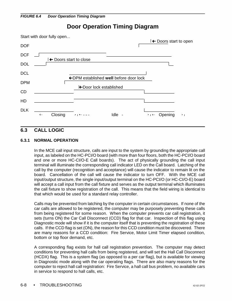
• TROUBLESHOOTING 42-02-2P226-8
FIGURE 6.4 Door Operation Timing Diagram
Door Operation Timing Diagram
Start with door fully open... , ³ Doors start to open
DOF $$$$$$$$$$$$$$$$$$$$$$$$$$$$$$$$$$$$$$$$$$$$$,&&&&&&&&&&,$$$
DCF $$,&&&&&&&&&&&&&&&&&&&&&&&,$$$$$$$$$$$$$$$$$$$$$$$$$$$$
, ³ Doors start to close DOL $$$$$,&&&&&&&&&&&&&&&&&&&&&&&&&&&&&&&&&&&&&&&&&&,$$
DCL &&&&&&&&&&&&,$$$$$$$$$$$$$$$$$$$$$$$$$$$$$$$$$,&&&&&&&&&
, ³DPM established well before door lock DPM $$$$$$$$$$$$$,&&&&&&&&&&&&&&&&&&&&&&&&&&&&&&,$$$$$$$$$
,³Door lock established CD $$$$$$$$$$$$$$$$$,&&&&&&&&&&&&&&&&&&&&&&&&,$$$$$$$$$$$$$
HD $$$$$$$$$$$$$$$$$,&&&&&&&&&&&&&&&&&&&&&&&&,$$$$$$$$$$$$$
DLK $$$$$$$$$$$$$$$$$,&&&&&&&&&&&&&&&&&&&&&&&&,$$$$$$$$$$$$$
0 ² !!!Closing !! ÷ 0 ²SSS !!!!!!! Idle S!!!!!!!!!÷ 0 ²! Opening !÷ 0
6.3 CALL LOGIC
6.3.1 NORMAL OPERATION
In the MCE call input structure, calls are input to the system by grounding the appropriate callinput, as labeled on the HC-PCI/O board (with more than four floors, both the HC-PCI/O boardand one or more HC-CI/O-E Call boards). The act of physically grounding the call inputterminal will illuminate the corresponding call indicator LED on the Call board. Latching of thecall by the computer (recognition and acceptance) will cause the indicator to remain lit on theboard. Cancellation of the call will cause the indicator to turn OFF. With the MCE callinput/output structure, the single input/output terminal on the HC-PCI/O (or HC-CI/O-E) boardwill accept a call input from the call fixture and serves as the output terminal which illuminatesthe call fixture to show registration of the call. This means that the field wiring is identical tothat which would be used for a standard relay controller.
Calls may be prevented from latching by the computer in certain circumstances. If none of thecar calls are allowed to be registered, the computer may be purposely preventing these callsfrom being registered for some reason. When the computer prevents car call registration, itsets (turns ON) the Car Call Disconnect (CCD) flag for that car. Inspection of this flag usingDiagnostic mode will show if it is the computer itself that is preventing the registration of thesecalls. If the CCD flag is set (ON), the reason for this CCD condition must be discovered. Thereare many reasons for a CCD condition: Fire Service, Motor Limit Timer elapsed condition,bottom or top floor demand, etc.
A corresponding flag exists for hall call registration prevention. The computer may detectconditions for preventing hall calls from being registered, and will set the Hall Call Disconnect(HCDX) flag. This is a system flag (as opposed to a per car flag), but is available for viewingin Diagnostic mode along with the car operating flags. There are also many reasons for thecomputer to reject hall call registration: Fire Service, a hall call bus problem, no available carsin service to respond to hall calls, etc.
42-02-2P22 TROUBLESHOOTING • 6-9
NOTE: If it appears that there is a problem with a call, disconnect the field wire (orwires) from that call terminal in order to find out if the problem is on theboard or out in the field. The calls can be disconnected by unplugging theterminals or by removing individual wires. If the individual field wire isdisconnected, lightly tighten the screw on the terminal. If the screw is loosewhile trying to ground the terminal using a jumper, contact may not bemade.
NOTE: The resistor-fuse is an assembly made up of a 10 Volt zener diode and a22 ohm ¼ Watt resistor.
It should also be mentioned that if a call circuit becomes damaged or stuck ON due to a stuckpush-button, the elevator will release itself from the stuck call automatically. It will probablyreturn there later, but will again release itself automatically, thereby allowing continued servicein the building.
6.3.2 PREPARATION FOR TROUBLESHOOTING CALL CIRCUITS
Review Section 5.5 (External Memory mode) of this manual. Then, look at Table 5.6. It showswhere to look up the calls in the computer memory (addresses 0140 through 015F). By lookingat this memory, it is possible to see if a particular call is being recognized by the computer.
Prepare a jumper with one side connected to terminal #1 which is the same as ground(subplate is grounded), then use the other end to enter the call by grounding the call terminalin question.
6.3.3 TROUBLESHOOTING
1. Once the wires have been disconnected from the call input terminal, the system shouldbe turned ON and in a normal running configuration. Use Diagnostic mode on thecomputer as described previously to check the status of the HCDX flag and CCD flag.If they are ON, they will shut OFF hall calls and car calls respectively.
2. If HCDX and CCD are normal (or OFF), take a meter with a high input impedance (suchas a good digital meter) and check the voltage on the call terminal in question.Depending on the voltage that the call circuits were set up for, the reading should beapproximately the voltage on the call terminal called for (or up to 15% less). If thevoltage is lower than what is specified, and the call terminal is on an HC-CI/O-E board,turn OFF the power and remove the resistor-fuse associated with the call terminal (i.e.,if the call terminal is the fifth one from the bottom, remove the fifth resistor-fuse fromthe bottom). Turn the power back ON. The reading should be the voltage as discussedabove. Note: the HC-PCI/O board does not have these resistor-fuses.
3. If the job has more than four floors, the controller will include at least one HC-CI/O-ECall Input/Output board. If the problem terminal is on this board and the necessaryvoltage does not read on the terminal, make sure the jumper plug (or header) is inposition on the Call board. The jumper plug socket is on the right-hand side of the Callboard near the call indicators. If a Call board is replaced, this jumper plug must alwaysbe transferred to the new board and stay in the same position. If this plug is notinstalled, any calls on the new board may become registered if the field wiring is notconnected, so make sure the jumper plug is in place (see Figure 6.5).
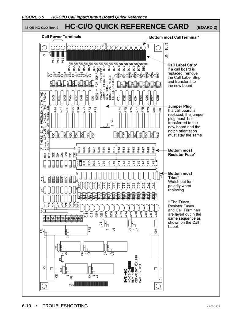
• TROUBLESHOOTING 42-02-2P226-10
FIGURE 6.5 HC-CI/O Call Input/Output Board Quick Reference
42-QR-HC-CI/O Rev. 2 HC-CI/O QUICK REFERENCE CARD (BOARD 2)
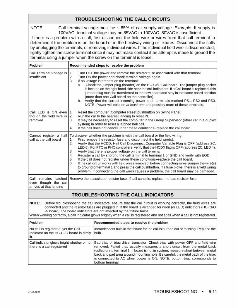
42-02-2P22 TROUBLESHOOTING • 6-11
TROUBLESHOOTING THE CALL CIRCUITS
NOTE: Call terminal voltage must be $ 85% of call supply voltage. Example: If supply is100VAC, terminal voltage may be 85VAC to 100VAC. 80VAC is insufficient.
If there is a problem with a call, first disconnect the field wire or wires from that call terminal todetermine if the problem is on the board or in the hoistway wiring or fixtures. Disconnect the callsby unplugging the terminals, or removing individual wires. If the individual field wire is disconnected,lightly tighten the screw terminal since it may not make contact if an attempt is made to ground theterminal using a jumper when the screw on the terminal is loose.
Problem Recommended steps to resolve the problem
Call Terminal Voltage isinsufficient
1. Turn OFF the power and remove the resistor fuse associated with that terminal. 2. Turn ON the power and check terminal voltage again.3. If no voltage is present on the terminal:
a. Check the jumper plug (header) on the HC-CI/O Call board. The jumper plug socketis located on the right hand side near the call indicators. If a Call board is replaced, thisjumper plug must be transferred to the new board and stay in the same board position(more than one Call board on the controller).
b. Verify that the correct incoming power is on terminals marked PS1, PS2 and PS3.NOTE: Power will exist on at least one and possibly more of these terminals.
Call LED is ON eventhough the field wire isremoved
1. Reset the computer (Computer Reset pushbutton on Swing Panel). 2. Run the car to the nearest landing to reset PI. 3. It may be necessary to reset the computer in the Group Supervisor (other car in a duplex
system) in order to reset a latched hall call.4. If the call does not cancel under these conditions--replace the call board
Cannot register a hallcall at the call board
To discover whether the problem is with the call board or the field wiring: 1. First remove the resistor fuse and disconnect the field wire(s). 2. Verify that the HCDD, Hall Call Disconnect Computer Variable Flag is OFF (address 2C,
LED 6). For PTC or PHC controllers, verify that the HCDX flag is OFF (address 2C, LED 4).3. Verify that there is proper voltage on the call terminal. 4. Register a call by shorting the call terminal to terminal 1 or GND and verify with EOD.5. If the call does not register under these conditions--replace the call board.6. If the call circuit works with field wires removed, before connecting wires, jumper the wire(s)
to ground or terminal 1 and press the call pushbutton. If a fuse blows, there is a field wiringproblem. If connecting the call wires causes a problem, the call board may be damaged.
Call remains latchedeven though the cararrives at that landing
Remove the associated resistor fuse. If call cancels, replace the bad resistor fuse.
TROUBLESHOOTING THE CALL INDICATORS
NOTE: Before troubleshooting the call indicators, ensure that the call circuit is working correctly, the field wires areconnected and the resistor fuses are plugged in. If the board is arranged for neon (or LED) indicators (HC-CI/O-N board), the board indicators are not affected by the fixture bulbs.
When working correctly, a call indicator glows brightly when a call is registered and not at all when a call is not registered.
Problem Recommended steps to resolve the problem
No call is registered, yet the CallIndicator on the HC-CI/O board is dimlylit.
Incandescent bulb in the fixture for the call is burned out or missing. Replace thebulb.
Call indicator glows bright whether or notthere is a call registered
Bad triac or triac driver transistor. Check triac with power OFF and field wireremoved. Failed triac usually measures a short circuit from the metal back(collector) to terminal 1. If board is not in system, measure short between metalback and pad area around mounting hole. Be careful, the metal back of the triacis connected to AC when power is ON. NOTE: bottom triac corresponds tobottom terminal.
• TROUBLESHOOTING 42-02-2P226-12
4. For both the HC-PCI/O board and the HC-CI/O-E board(s), make sure that the correctvoltage is coming into the terminals on the board marked PS1, PS2, and PS3. Notethat there may be power on all three of these terminals, only two, or at least one,depending on the type of calls on the board.
5. Once the proper voltage is on the call terminal in question, use External Memory modeand Table 5.6 to examine the call in the computer memory. The call should not be ON.If it is, reset the computer for that car. Let the car find itself or run it to a terminallanding to make sure the CCD flag is turned OFF. If the resistor-fuse has beenremoved (if necessary), the field wires disconnected, HCDX and CCD both OFF, andthe proper voltage exists on the call terminal, the call should not be registered. Shortingthe call terminal to terminal 1 (or ground) should register the call in the computeraccording to External Memory mode. This does not mean the call registered light onthe Call board will work correctly. If the call does not register and cancel under theconditions mentioned in this step, then a condition exists on the board that cannot becorrected in the field and the board should be replaced.
6. If the call works correctly in the previous step, and it does not register, and the boardis not arranged for neon indicator lamps in the fixtures, the indicator for that call on theboard will glow dimly. If the board is arranged for neon indicators, the call indicator onthe board will not glow. In this case, a dim glow indicates that the incandescent bulbin the fixture is burned out (when the call has the resistor-fuse plugged in and the fieldwire connected normally).
7. With a known good resistor-fuse plugged into the proper call position, check to see thatthe indicator on the Call board works correctly (glows brightly when the call is registeredand glows dimly, or not at all, when the call is not registered). If the call indicator burnsbrightly when the resistor-fuse is plugged in and shows no change in brightnesswhether the call is registered or not, then there is a bad triac or triac driver transistor.The triacs are plug-in types and can be easily replaced. Usually, if a triac has failed,it will measure as a short circuit between the metal base and terminal 1 with the powerdisconnected and the field wire removed. If the Call board is not in the system, checkfor a short circuit between the metal base of the triac to any pad area around a mount-ing screw hole. On the HC-CI/O-E board, the bottom most triac corresponds to thebottom most terminal, and terminals and triacs are corresponding from there on up (seeFigure 6.5). On the HC-PCI/O board, the triacs are labeled the same as the callterminals (see Figure 6.1).
8. If the call has passed all of the previous tests, then it should be working properly whilethe field wires are not attached. Before reconnecting the field wires, jumper the wire(or wires) to terminal 1 and go out to that hall or car call push-button and press it. If afuse blows, then a field wiring problem exists. If everything seems okay, then connectthe call wires and test it. If connecting the call wires causes a problem, the board mayhave again been damaged. In any event, once the board checks out okay, any otherproblems will probably be field wiring problems and should be investigated.
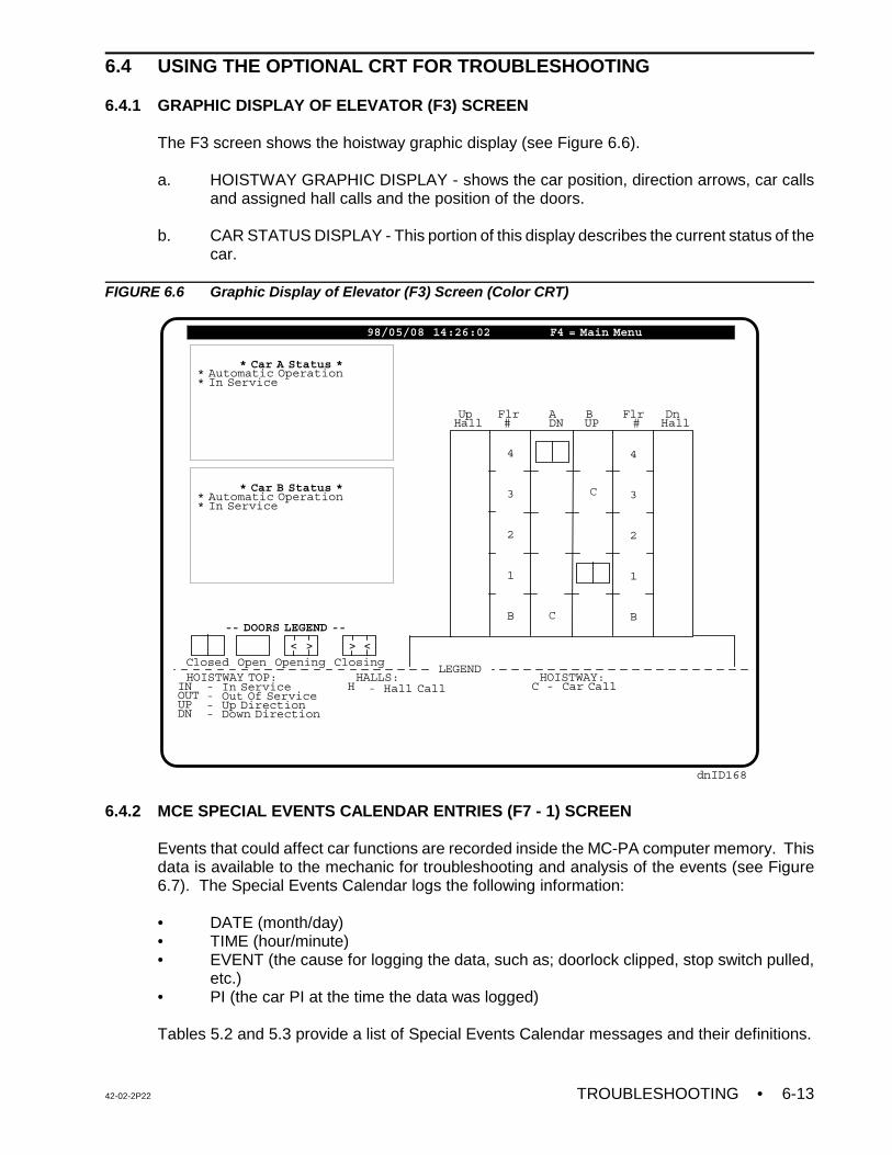
42-02-2P22 TROUBLESHOOTING • 6-13
LEGEND HOISTWAY TOP: INOUTUPDN
HOISTWAY: C
HALLS: H- In Service
- Out Of Service- Up Direction- Down Direction
- Car Call- Hall Call
Up Flr A B Flr DnHall # DN UP # Hall
dnID168
4
3
2
1
B
4
3
2
1
B
* Car A Status ** Automatic Operation* In Service
* Car B Status ** Automatic Operation* In Service
-- DOORS LEGEND --
Closed Open Opening Closing
< > > <
98/05/08 14:26:02 F4 = Main Menu
C
C
6.4 USING THE OPTIONAL CRT FOR TROUBLESHOOTING
6.4.1 GRAPHIC DISPLAY OF ELEVATOR (F3) SCREEN
The F3 screen shows the hoistway graphic display (see Figure 6.6).
a. HOISTWAY GRAPHIC DISPLAY - shows the car position, direction arrows, car callsand assigned hall calls and the position of the doors.
b. CAR STATUS DISPLAY - This portion of this display describes the current status of thecar.
FIGURE 6.6 Graphic Display of Elevator (F3) Screen (Color CRT)
6.4.2 MCE SPECIAL EVENTS CALENDAR ENTRIES (F7 - 1) SCREEN
Events that could affect car functions are recorded inside the MC-PA computer memory. Thisdata is available to the mechanic for troubleshooting and analysis of the events (see Figure6.7). The Special Events Calendar logs the following information:
• DATE (month/day)• TIME (hour/minute)• EVENT (the cause for logging the data, such as; doorlock clipped, stop switch pulled,
etc.)• PI (the car PI at the time the data was logged)
Tables 5.2 and 5.3 provide a list of Special Events Calendar messages and their definitions.
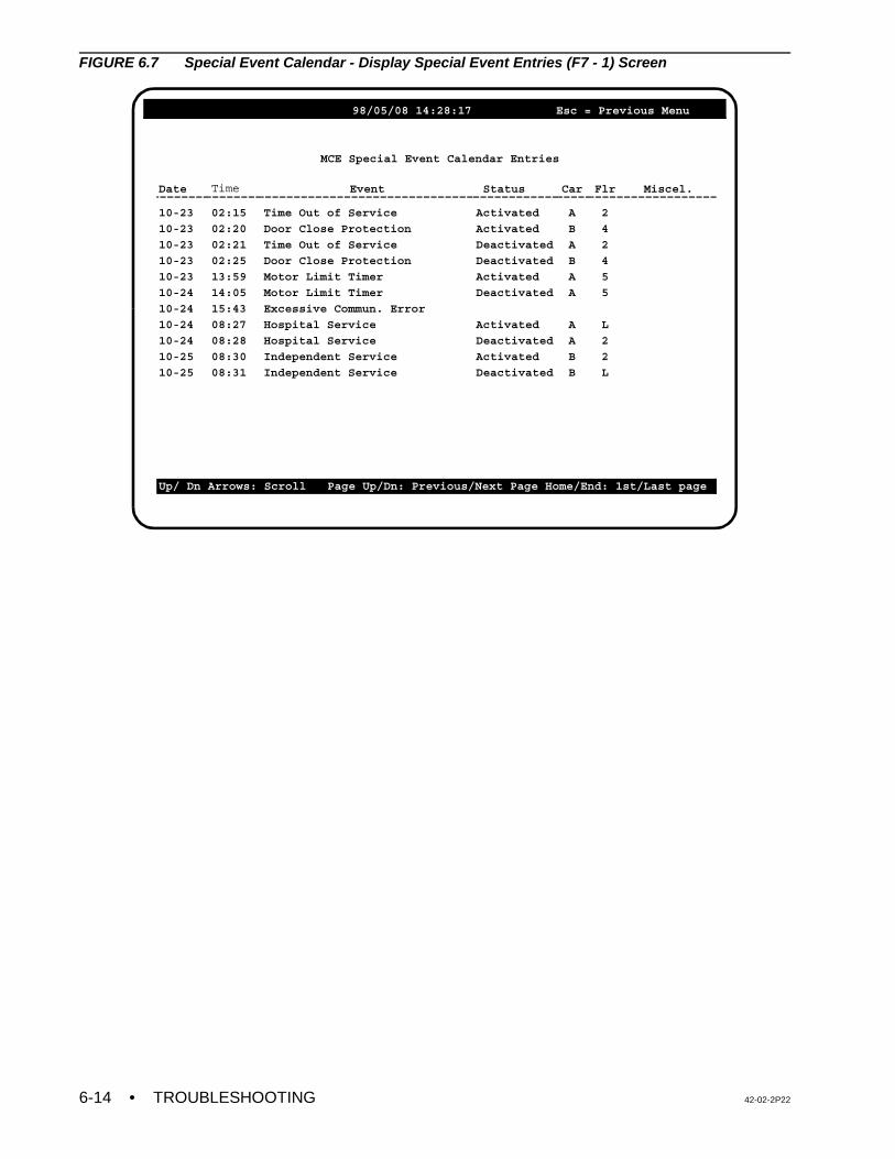
• TROUBLESHOOTING 42-02-2P226-14
98/05/08 14:28:17 Esc = Previous Menu
MCE Special Event Calendar Entries
Date Time Event Status Car Flr Miscel.
10-23
10-23
10-23
10-23
10-23
10-24
10-24
10-24
10-24
10-25
10-25
02:15
02:20
02:21
02:25
13:59
14:05
15:43
08:27
08:28
08:30
08:31
Time Out of Service
Door Close Protection
Time Out of Service
Door Close Protection
Motor Limit Timer
Motor Limit Timer
Excessive Commun. Error
Hospital Service
Hospital Service
Independent Service
Independent Service
Activated
Activated
Deactivated
Deactivated
Activated
Deactivated
Activated
Deactivated
Activated
Deactivated
A
B
A
B
A
A
A
A
B
B
2
4
2
4
5
5
L
2
2
L
Up/ Dn Arrows: Scroll Page Up/Dn: Previous/Next Page Home/End: 1st/Last page
FIGURE 6.7 Special Event Calendar - Display Special Event Entries (F7 - 1) Screen

42-02-2P22 TROUBLESHOOTING • 6-15
NOTE: The drive software has been modified for this application. Some of theparameters in the parameter sheet are different and are not available in thedrive manual. If a drive has been replaced in the field, all of the driveparameters should be entered manually and should be verified accordingto the parameter sheet shipped with the controller.
NOTE: Many of the safety relays that populate the main PC boards (SC-SB2K andSC-BASE) are soldered to the board, therefore it will be necessary toreplace the entire board when any relay fails to operate as intended.
6.5 TROUBLESHOOTING THE G5 / GPD515 AC DRIVE
The VFAC drive’s digital operator display must read as follows during power up: Frequencyreference U1-01=0. If any fault or problem is detected, then turn off the power and refer to theAlarms and Fault Displays section of the EMS/Yaskawa AC Drive Manual.
6.5.1 CAR DOES NOT MOVE ON INSPECTION
• Pick or Picked = relay energized• Drop or dropped = relay de-energized
If the car does not move on INSPECTION, check the following:
1. Relays SAFR1 and SAFR2 will drop and pick back up at the end of every run, but onlyif the code mandated “cycle tests” function as required. This means that after every runthe critical relays are dropped out to ensure that no contacts have welded. If a failureof the relays or overspeed logic is detected both SAFR1 and SAFR2 will not be allowedto pick. If this is the case, inspect the message scrolling on the MC-PCA-OA2K displayto determine which section of the hardware has failed.
PFLT Relay - The PFLT relay is mounted on the SC-BASE-x board and has a singlenormally open contact in the safety string, immediately following IDC20 and before theOL contact which feeds power to relays SAFR1 and SAFR2. The normally open contactof the PFLT relay is directly monitored by the MC-PCA-OA2K Main Processor throughthe PFLT input from and through the SC-HDIO board on IDC ASI1. The PFLT relayshould remain energized during Normal operation. This relay drops and causes anEmergency Shutdown and stops the car under the following conditions: ILO, ETS andcontract overspeed. The PFLT relay also turns OFF during PLD1 cycle testing.
2. Verify that contactors PM (Main) and BK (Brake) pick when the direction relays, U andD, are picked). If PM and BK do not pick, check the related circuit (MB) as shown in thecontroller drawings. Check for any fault that is displayed on the drive keypad before andafter picking the direction on Inspection. When the direction is picked on Inspection,relays RE and CHDT on the SC-SB2K board should be picked. Also relays PT1 andPT2 on the HC-ACI board should be picked. If these relays are not picked, check for120VAC on terminals 9, 10,12 and 20 on the SC-SB2K Main Safety Relay Board. Ifthere is no voltage on these terminals, refer to the controller drawings to find theproblem. Note that relays SAFR1, SAFR2, CNP and RDY should also be picked.
3. Verify that the drive receives the direction enable and inspection speed commandsignals from the (HC-ACI) board. The drive key pad should display the commanded Hz
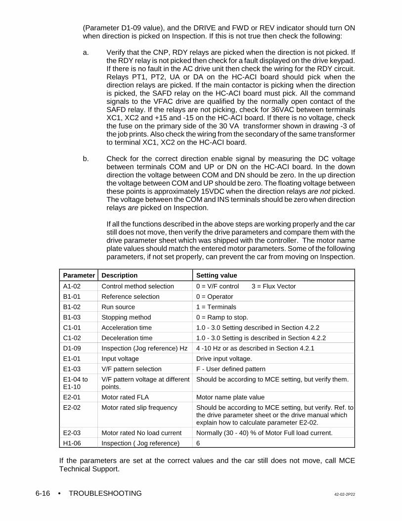
• TROUBLESHOOTING 42-02-2P226-16
(Parameter D1-09 value), and the DRIVE and FWD or REV indicator should turn ONwhen direction is picked on Inspection. If this is not true then check the following:
a. Verify that the CNP, RDY relays are picked when the direction is not picked. Ifthe RDY relay is not picked then check for a fault displayed on the drive keypad.If there is no fault in the AC drive unit then check the wiring for the RDY circuit.Relays PT1, PT2, UA or DA on the HC-ACI board should pick when thedirection relays are picked. If the main contactor is picking when the directionis picked, the SAFD relay on the HC-ACI board must pick. All the commandsignals to the VFAC drive are qualified by the normally open contact of theSAFD relay. If the relays are not picking, check for 36VAC between terminalsXC1, XC2 and +15 and -15 on the HC-ACI board. If there is no voltage, checkthe fuse on the primary side of the 30 VA transformer shown in drawing -3 ofthe job prints. Also check the wiring from the secondary of the same transformerto terminal XC1, XC2 on the HC-ACI board.
b. Check for the correct direction enable signal by measuring the DC voltagebetween terminals COM and UP or DN on the HC-ACI board. In the downdirection the voltage between COM and DN should be zero. In the up directionthe voltage between COM and UP should be zero. The floating voltage betweenthese points is approximately 15VDC when the direction relays are not picked.The voltage between the COM and INS terminals should be zero when directionrelays are picked on Inspection.
If all the functions described in the above steps are working properly and the carstill does not move, then verify the drive parameters and compare them with thedrive parameter sheet which was shipped with the controller. The motor nameplate values should match the entered motor parameters. Some of the followingparameters, if not set properly, can prevent the car from moving on Inspection.
Parameter Description Setting value
A1-02 Control method selection 0 = V/F control 3 = Flux Vector
B1-01 Reference selection 0 = Operator
B1-02 Run source 1 = Terminals
B1-03 Stopping method 0 = Ramp to stop.
C1-01 Acceleration time 1.0 - 3.0 Setting described in Section 4.2.2
C1-02 Deceleration time 1.0 - 3.0 Setting is described in Section 4.2.2
D1-09 Inspection (Jog reference) Hz 4 -10 Hz or as described in Section 4.2.1
E1-01 Input voltage Drive input voltage.
E1-03 V/F pattern selection F - User defined pattern
E1-04 toE1-10
V/F pattern voltage at differentpoints.
Should be according to MCE setting, but verify them.
E2-01 Motor rated FLA Motor name plate value
E2-02 Motor rated slip frequency Should be according to MCE setting, but verify. Ref. tothe drive parameter sheet or the drive manual whichexplain how to calculate parameter E2-02.
E2-03 Motor rated No load current Normally (30 - 40) % of Motor Full load current.
H1-06 Inspection ( Jog reference) 6
If the parameters are set at the correct values and the car still does not move, call MCETechnical Support.
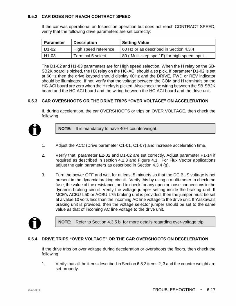
42-02-2P22 TROUBLESHOOTING • 6-17
NOTE: It is mandatory to have 40% counterweight.
NOTE: Refer to Section 4.3.5 b. for more details regarding over-voltage trip.
6.5.2 CAR DOES NOT REACH CONTRACT SPEED
If the car was operational on Inspection operation but does not reach CONTRACT SPEED,verify that the following drive parameters are set correctly:
Parameter Description Setting Value
D1-02 High speed reference 60 Hz or as described in Section 4.3.4
H1-03 Terminal 5 select 80 ( Mult -step spd 1F) for high speed input.
The D1-02 and H1-03 parameters are for High speed selection. When the H relay on the SB-SB2K board is picked, the HX relay on the HC-ACI should also pick. If parameter D1-02 is setat 60Hz then the drive keypad should display 60Hz and the DRIVE, FWD or REV indicatorshould be illuminated. If not, verify that the voltage between the COM and H terminals on theHC-ACI board are zero when the H relay is picked. Also check the wiring between the SB-SB2Kboard and the HC-ACI board and the wiring between the HC-ACI board and the drive unit.
6.5.3 CAR OVERSHOOTS OR THE DRIVE TRIPS “OVER VOLTAGE” ON ACCELERATION
If, during acceleration, the car OVERSHOOTS or trips on OVER VOLTAGE, then check thefollowing:
1. Adjust the ACC (Drive parameter C1-01, C1-07) and increase acceleration time.
2. Verify that parameter E2-02 and D1-02 are set correctly. Adjust parameter P1-14 ifrequired as described in section 4.2.3 and Figure 4.1. For Flux Vector applicationsadjust the gain parameters as described in Section 4.3.4 (g).
3. Turn the power OFF and wait for at least 5 minuets so that the DC BUS voltage is notpresent in the dynamic braking circuit. Verify this by using a multi-meter to check thefuse, the value of the resistance, and to check for any open or loose connections in thedynamic braking circuit. Verify the voltage jumper setting inside the braking unit. IfMCE's ACBU-L50 or ACBU-L75 braking unit is provided, then the jumper must be setat a value 10 volts less than the incoming AC line voltage to the drive unit. If Yaskawa'sbraking unit is provided, then the voltage selector jumper should be set to the samevalue as that of incoming AC line voltage to the drive unit.
6.5.4 DRIVE TRIPS “OVER VOLTAGE” OR THE CAR OVERSHOOTS ON DECELERATION
If the drive trips on over voltage during deceleration or overshoots the floors, then check thefollowing:
1. Verify that all the items described in Section 6.5.3 items 2, 3 and the counter weight areset properly.
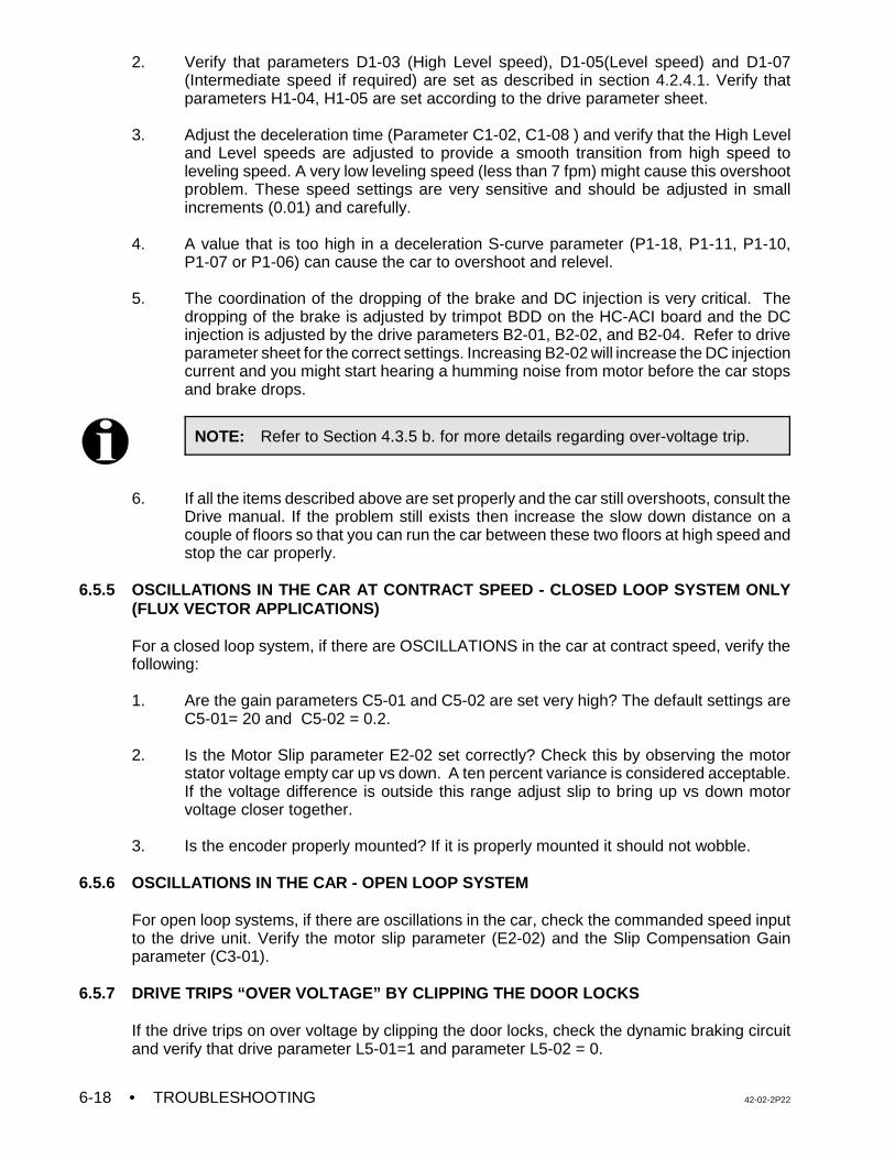
• TROUBLESHOOTING 42-02-2P226-18
NOTE: Refer to Section 4.3.5 b. for more details regarding over-voltage trip.
2. Verify that parameters D1-03 (High Level speed), D1-05(Level speed) and D1-07(Intermediate speed if required) are set as described in section 4.2.4.1. Verify thatparameters H1-04, H1-05 are set according to the drive parameter sheet.
3. Adjust the deceleration time (Parameter C1-02, C1-08 ) and verify that the High Leveland Level speeds are adjusted to provide a smooth transition from high speed toleveling speed. A very low leveling speed (less than 7 fpm) might cause this overshootproblem. These speed settings are very sensitive and should be adjusted in smallincrements (0.01) and carefully.
4. A value that is too high in a deceleration S-curve parameter (P1-18, P1-11, P1-10,P1-07 or P1-06) can cause the car to overshoot and relevel.
5. The coordination of the dropping of the brake and DC injection is very critical. Thedropping of the brake is adjusted by trimpot BDD on the HC-ACI board and the DCinjection is adjusted by the drive parameters B2-01, B2-02, and B2-04. Refer to driveparameter sheet for the correct settings. Increasing B2-02 will increase the DC injectioncurrent and you might start hearing a humming noise from motor before the car stopsand brake drops.
6. If all the items described above are set properly and the car still overshoots, consult theDrive manual. If the problem still exists then increase the slow down distance on acouple of floors so that you can run the car between these two floors at high speed andstop the car properly.
6.5.5 OSCILLATIONS IN THE CAR AT CONTRACT SPEED - CLOSED LOOP SYSTEM ONLY(FLUX VECTOR APPLICATIONS)
For a closed loop system, if there are OSCILLATIONS in the car at contract speed, verify thefollowing:
1. Are the gain parameters C5-01 and C5-02 are set very high? The default settings areC5-01= 20 and C5-02 = 0.2.
2. Is the Motor Slip parameter E2-02 set correctly? Check this by observing the motor
stator voltage empty car up vs down. A ten percent variance is considered acceptable.If the voltage difference is outside this range adjust slip to bring up vs down motorvoltage closer together.
3. Is the encoder properly mounted? If it is properly mounted it should not wobble.
6.5.6 OSCILLATIONS IN THE CAR - OPEN LOOP SYSTEM
For open loop systems, if there are oscillations in the car, check the commanded speed inputto the drive unit. Verify the motor slip parameter (E2-02) and the Slip Compensation Gainparameter (C3-01).
6.5.7 DRIVE TRIPS “OVER VOLTAGE” BY CLIPPING THE DOOR LOCKS
If the drive trips on over voltage by clipping the door locks, check the dynamic braking circuitand verify that drive parameter L5-01=1 and parameter L5-02 = 0.
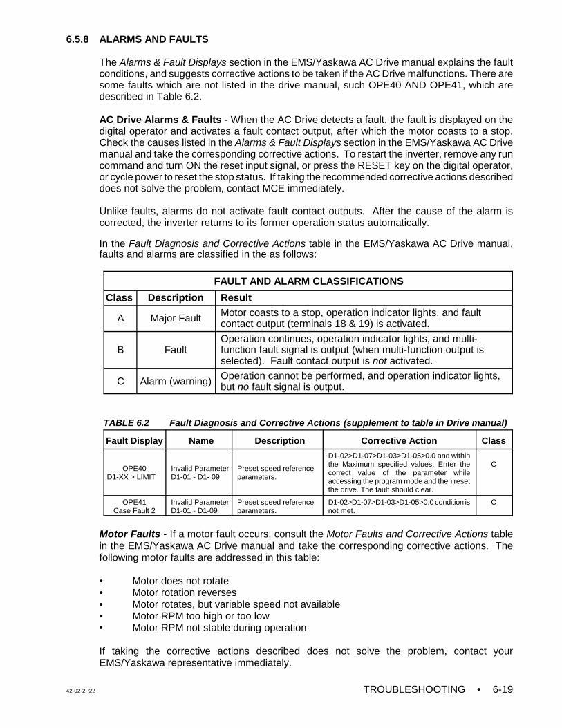
42-02-2P22 TROUBLESHOOTING • 6-19
6.5.8 ALARMS AND FAULTS
The Alarms & Fault Displays section in the EMS/Yaskawa AC Drive manual explains the faultconditions, and suggests corrective actions to be taken if the AC Drive malfunctions. There aresome faults which are not listed in the drive manual, such OPE40 AND OPE41, which aredescribed in Table 6.2.
AC Drive Alarms & Faults - When the AC Drive detects a fault, the fault is displayed on thedigital operator and activates a fault contact output, after which the motor coasts to a stop.Check the causes listed in the Alarms & Fault Displays section in the EMS/Yaskawa AC Drivemanual and take the corresponding corrective actions. To restart the inverter, remove any runcommand and turn ON the reset input signal, or press the RESET key on the digital operator,or cycle power to reset the stop status. If taking the recommended corrective actions describeddoes not solve the problem, contact MCE immediately.
Unlike faults, alarms do not activate fault contact outputs. After the cause of the alarm iscorrected, the inverter returns to its former operation status automatically.
In the Fault Diagnosis and Corrective Actions table in the EMS/Yaskawa AC Drive manual,faults and alarms are classified in the as follows:
FAULT AND ALARM CLASSIFICATIONS
Class Description Result
A Major Fault Motor coasts to a stop, operation indicator lights, and faultcontact output (terminals 18 & 19) is activated.
B FaultOperation continues, operation indicator lights, and multi-function fault signal is output (when multi-function output isselected). Fault contact output is not activated.
C Alarm (warning) Operation cannot be performed, and operation indicator lights,but no fault signal is output.
TABLE 6.2 Fault Diagnosis and Corrective Actions (supplement to table in Drive manual)
Fault Display Name Description Corrective Action Class
OPE40D1-XX > LIMIT
Invalid ParameterD1-01 - D1- 09
Preset speed referenceparameters.
D1-02>D1-07>D1-03>D1-05>0.0 and withinthe Maximum specified values. Enter thecorrect value of the parameter whileaccessing the program mode and then resetthe drive. The fault should clear.
C
OPE41Case Fault 2
Invalid ParameterD1-01 - D1-09
Preset speed referenceparameters.
D1-02>D1-07>D1-03>D1-05>0.0 condition isnot met.
C
Motor Faults - If a motor fault occurs, consult the Motor Faults and Corrective Actions tablein the EMS/Yaskawa AC Drive manual and take the corresponding corrective actions. Thefollowing motor faults are addressed in this table:
• Motor does not rotate• Motor rotation reverses• Motor rotates, but variable speed not available• Motor RPM too high or too low• Motor RPM not stable during operation
If taking the corrective actions described does not solve the problem, contact yourEMS/Yaskawa representative immediately.
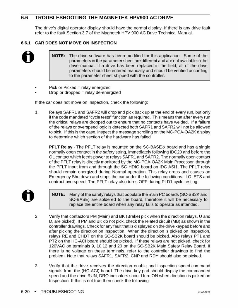
• TROUBLESHOOTING 42-02-2P226-20
NOTE: The drive software has been modified for this application. Some of theparameters in the parameter sheet are different and are not available in thedrive manual. If a drive has been replaced in the field, all of the driveparameters should be entered manually and should be verified accordingto the parameter sheet shipped with the controller.
NOTE: Many of the safety relays that populate the main PC boards (SC-SB2K andSC-BASE) are soldered to the board, therefore it will be necessary toreplace the entire board when any relay fails to operate as intended.
6.6 TROUBLESHOOTING THE MAGNETEK HPV900 AC DRIVE
The drive’s digital operator display should have the normal display. If there is any drive faultrefer to the fault Section 3.7 of the Magnetek HPV 900 AC Drive Technical Manual.
6.6.1 CAR DOES NOT MOVE ON INSPECTION
• Pick or Picked = relay energized• Drop or dropped = relay de-energized
If the car does not move on Inspection, check the following:
1. Relays SAFR1 and SAFR2 will drop and pick back up at the end of every run, but onlyif the code mandated “cycle tests” function as required. This means that after every runthe critical relays are dropped out to ensure that no contacts have welded. If a failureof the relays or overspeed logic is detected both SAFR1 and SAFR2 will not be allowedto pick. If this is the case, inspect the message scrolling on the MC-PCA-OA2K displayto determine which section of the hardware has failed.
PFLT Relay - The PFLT relay is mounted on the SC-BASE-x board and has a singlenormally open contact in the safety string, immediately following IDC20 and before theOL contact which feeds power to relays SAFR1 and SAFR2. The normally open contactof the PFLT relay is directly monitored by the MC-PCA-OA2K Main Processor throughthe PFLT input from and through the SC-HDIO board on IDC ASI1. The PFLT relayshould remain energized during Normal operation. This relay drops and causes anEmergency Shutdown and stops the car under the following conditions: ILO, ETS andcontract overspeed. The PFLT relay also turns OFF during PLD1 cycle testing.
2. Verify that contactors PM (Main) and BK (Brake) pick when the direction relays, U andD, are picked). If PM and BK do not pick, check the related circuit (MB) as shown in thecontroller drawings. Check for any fault that is displayed on the drive keypad before andafter picking the direction on Inspection. When the direction is picked on Inspection,relays RE and CHDT on the SC-SB2K board should be picked. Also relays PT1 andPT2 on the HC-ACI board should be picked. If these relays are not picked, check for120VAC on terminals 9, 10,12 and 20 on the SC-SB2K Main Safety Relay Board. Ifthere is no voltage on these terminals, refer to the controller drawings to find theproblem. Note that relays SAFR1, SAFR2, CNP and RDY should also be picked.
3. Verify that the drive receives the direction enable and inspection speed commandsignals from the (HC-ACI) board. The drive key pad should display the commandedspeed and the drive RUN, DRO indicators should turn ON when direction is picked onInspection. If this is not true then check the following:
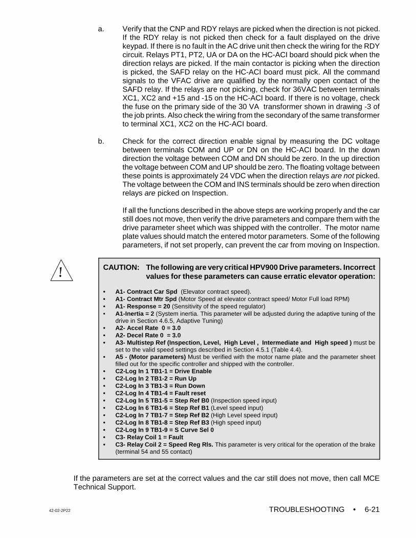
42-02-2P22 TROUBLESHOOTING • 6-21
CAUTION: The following are very critical HPV900 Drive parameters. Incorrectvalues for these parameters can cause erratic elevator operation:
• A1- Contract Car Spd (Elevator contract speed).• A1- Contract Mtr Spd (Motor Speed at elevator contract speed/ Motor Full load RPM)• A1- Response = 20 (Sensitivity of the speed regulator) • A1-Inertia = 2 (System inertia. This parameter will be adjusted during the adaptive tuning of the
drive in Section 4.6.5, Adaptive Tuning) • A2- Accel Rate 0 = 3.0 • A2- Decel Rate 0 = 3.0 • A3- Multistep Ref (Inspection, Level, High Level , Intermediate and High speed ) must be
set to the valid speed settings described in Section 4.5.1 (Table 4.4).• A5 - (Motor parameters) Must be verified with the motor name plate and the parameter sheet
filled out for the specific controller and shipped with the controller.• C2-Log In 1 TB1-1 = Drive Enable• C2-Log In 2 TB1-2 = Run Up• C2-Log In 3 TB1-3 = Run Down• C2-Log In 4 TB1-4 = Fault reset• C2-Log In 5 TB1-5 = Step Ref B0 (Inspection speed input)• C2-Log In 6 TB1-6 = Step Ref B1 (Level speed input) • C2-Log In 7 TB1-7 = Step Ref B2 (High Level speed input)• C2-Log In 8 TB1-8 = Step Ref B3 (High speed input)• C2-Log In 9 TB1-9 = S Curve Sel 0• C3- Relay Coil 1 = Fault• C3- Relay Coil 2 = Speed Reg Rls. This parameter is very critical for the operation of the brake
(terminal 54 and 55 contact)
a. Verify that the CNP and RDY relays are picked when the direction is not picked.If the RDY relay is not picked then check for a fault displayed on the drivekeypad. If there is no fault in the AC drive unit then check the wiring for the RDYcircuit. Relays PT1, PT2, UA or DA on the HC-ACI board should pick when thedirection relays are picked. If the main contactor is picking when the directionis picked, the SAFD relay on the HC-ACI board must pick. All the commandsignals to the VFAC drive are qualified by the normally open contact of theSAFD relay. If the relays are not picking, check for 36VAC between terminalsXC1, XC2 and +15 and -15 on the HC-ACI board. If there is no voltage, checkthe fuse on the primary side of the 30 VA transformer shown in drawing -3 ofthe job prints. Also check the wiring from the secondary of the same transformerto terminal XC1, XC2 on the HC-ACI board.
b. Check for the correct direction enable signal by measuring the DC voltagebetween terminals COM and UP or DN on the HC-ACI board. In the downdirection the voltage between COM and DN should be zero. In the up directionthe voltage between COM and UP should be zero. The floating voltage betweenthese points is approximately 24 VDC when the direction relays are not picked.The voltage between the COM and INS terminals should be zero when directionrelays are picked on Inspection.
If all the functions described in the above steps are working properly and the carstill does not move, then verify the drive parameters and compare them with thedrive parameter sheet which was shipped with the controller. The motor nameplate values should match the entered motor parameters. Some of the followingparameters, if not set properly, can prevent the car from moving on Inspection.
If the parameters are set at the correct values and the car still does not move, then call MCETechnical Support.
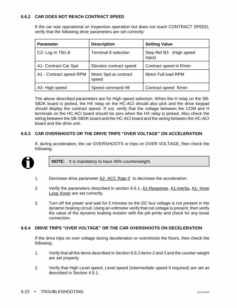
• TROUBLESHOOTING 42-02-2P226-22
NOTE: It is mandatory to have 40% counterweight.
6.6.2 CAR DOES NOT REACH CONTRACT SPEED
If the car was operational on Inspection operation but does not reach CONTRACT SPEED,verify that the following drive parameters are set correctly:
Parameter Description Setting Value
C2- Log In TB1-8 Terminal 8 selection Step Ref B3 (High speedinput)
A1- Contract Car Spd Elevator contract speed Contract speed in ft/min
A1 - Contract speed RPM Motor Spd at contractspeed
Motor Full load RPM
A3- High speed Speed command #8 Contract speed ft/min
The above described parameters are for High speed selection. When the H relay on the SB-SB2K board is picked, the HX relay on the HC-ACI should also pick and the drive keypadshould display the contract speed. If not, verify that the voltage between the COM and Hterminals on the HC-ACI board should be zero when the HX relay is picked. Also check thewiring between the SB-SB2K board and the HC-ACI board and the wiring between the HC-ACIboard and the drive unit.
6.6.3 CAR OVERSHOOTS OR THE DRIVE TRIPS “OVER VOLTAGE” ON ACCELERATION
If, during acceleration, the car OVERSHOOTS or trips on OVER VOLTAGE, then check thefollowing:
1. Decrease drive parameter A2- ACC Rate 0 to decrease the acceleration.
2. Verify the parameters described in section 6.6.1, A1-Response, A1-Inertia, A1- InnerLoop Xover are set correctly.
3. Turn off the power and wait for 5 minutes so the DC bus voltage is not present in thedynamic braking circuit. Using an voltmeter verify that not voltage is present, then verifythe value of the dynamic braking resistor with the job prints and check for any looseconnection.
6.6.4 DRIVE TRIPS “OVER VOLTAGE” OR THE CAR OVERSHOOTS ON DECELERATION
If the drive trips on over voltage during deceleration or overshoots the floors, then check thefollowing:
1. Verify that all the items described in Section 6.6.3 items 2 and 3 and the counter weightare set properly.
2. Verify that High Level speed, Level speed (Intermediate speed if required) are set asdescribed in Section 4.5.1.
42-02-2P22 TROUBLESHOOTING • 6-23
3. Increase the deceleration parameter A2- Decel Rate 0 and verify that the High Leveland Level speeds are adjusted to provide a smooth transition from high speed toleveling speed.
4. If the value of parameter A2- Lev Jerk Rate 0 is too high it can cause the car toovershoot and relevel.
5. If all the items described above are set properly and the car still overshoots, consult theDrive manual. If the problem still exists then increase the slow down distance on acouple of floors so that you can run the car between these floors at high speed and stopthe car properly.
6.6.5 OSCILLATIONS IN THE CAR AT CONTRACT SPEED
The HPV 900 series drive is used for Flux Vector applications. If there are OSCILLATIONS inthe car at contract speed, then verify the following:
1. Are the gain parameters are set two high (A1-Response, A1-Inner Loop Xover)?
2. Are the Motor parameters (A5 - Motor) set correctly?
3. Is the encoder properly mounted? If it is properly mounted it should not oscillate.
6.6.6 DRIVE TRIPS “OVER VOLTAGE” BY CLIPPING THE DOOR LOCKS
If the drive trips on over voltage by clipping the door locks, check the dynamic braking circuitand verify that drive parameters A1- Flt Reset Delay = 5 , A1 - Flt Reset / Hour = 3 .
6.6.7 ALARMS AND FAULTS
Refer to the fault section 3.7 in the Magnetek HPV 900 AC Drive Technical Manual.
• TROUBLESHOOTING 42-02-2P226-24
NOTE: The drive software has been modified for this application. Some of theparameters in the parameter sheet are different and are not available in thedrive manual. If a drive has been replaced in the field, all of the driveparameters should be entered manually and should be verified accordingto the parameter sheet shipped with the controller.
NOTE: Many of the safety relays that populate the main PC boards (SC-SB2K andSC-BASE) are soldered to the board, therefore it will be necessary toreplace the entire board when any relay fails to operate as intended.
6.7 TROUBLESHOOTING THE TORQMAX F4 AC DRIVE
The drive’s digital operator display should have the normal display. If there is any drive faultdisplayed, refer to Section 6.7.7 in this manual or the fault section in TORQMAX F4 DriveTechnical Manual.
6.7.1 CAR THE DOES NOT MOVE ON INSPECTION
• Pick or Picked = relay energized• Drop or dropped = relay de-energized
If the car does not move on Inspection, check the following:
1. Relays SAFR1 and SAFR2 will drop and pick back up at the end of every run, but onlyif the code mandated “cycle tests” function as required. This means that after every runthe critical relays are dropped out to ensure that no contacts have welded. If a failureof the relays or overspeed logic is detected both SAFR1 and SAFR2 will not be allowedto pick. If this is the case, inspect the message scrolling on the MC-PCA-OA2K displayto determine which section of the hardware has failed.
PFLT Relay - The PFLT relay is mounted on the SC-BASE-x board and has a singlenormally open contact in the safety string, immediately following IDC20 and before theOL contact which feeds power to relays SAFR1 and SAFR2. The normally open contactof the PFLT relay is directly monitored by the MC-PCA-OA2K Main Processor throughthe PFLT input from and through the SC-HDIO board on IDC ASI1. The PFLT relayshould remain energized during Normal operation. This relay drops and causes anEmergency Shutdown and stops the car under the following conditions: ILO, ETS andcontract overspeed. The PFLT relay also turns OFF during PLD1 cycle testing.
2. Verify that contactors PM (Main) and BK (Brake) pick when the direction relays, U andD, are picked). If PM and BK do not pick, check the related circuit (MB) as shown in thecontroller drawings. Check for any fault that is displayed on the drive keypad before andafter picking the direction on Inspection. When the direction is picked on Inspection,relays RE and CHDT on the SC-SB2K board should be picked. Also relays PT1 andPT2 on the HC-ACI board should be picked. If these relays are not picked, check for120VAC on terminals 9, 10,12 and 20 on the SC-SB2K Main Safety Relay Board. Ifthere is no voltage on these terminals, refer to the controller drawings to find theproblem. Note that relays SAFR1, SAFR2, CNP and RDY should also be picked.
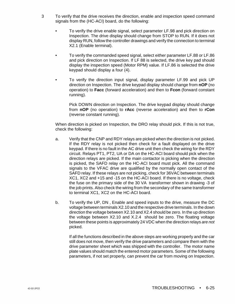
42-02-2P22 TROUBLESHOOTING • 6-25
3 To verify that the drive receives the direction, enable and inspection speed commandsignals from the (HC-ACI) board, do the following:
• To verify the drive enable signal, select parameter LF.98 and pick direction on
Inspection. The drive display should change from STOP to RUN. If it does notdisplay RUN, follow the controller drawings and verify the connection to terminalX2.1 (Enable terminal).
• To verify the commanded speed signal, select either parameter LF.88 or LF.86and pick direction on Inspection. If LF 88 is selected, the drive key pad shoulddisplay the inspection speed (Motor RPM) value. If LF.86 is selected the drivekeypad should display a four (4).
• To verify the direction input signal, display parameter LF.99 and pick UPdirection on Inspection. The drive keypad display should change from nOP (nooperation) to Facc (forward acceleration) and then to Fcon (forward constantrunning).
Pick DOWN direction on Inspection. The drive keypad display should changefrom nOP (no operation) to rAcc (reverse acceleration) and then to rCon(reverse constant running).
When direction is picked on Inspection, the DRO relay should pick. If this is not true,check the following:
a. Verify that the CNP and RDY relays are picked when the direction is not picked.If the RDY relay is not picked then check for a fault displayed on the drivekeypad. If there is no fault in the AC drive unit then check the wiring for the RDYcircuit. Relays PT1, PT2, UA or DA on the HC-ACI board should pick when thedirection relays are picked. If the main contactor is picking when the directionis picked, the SAFD relay on the HC-ACI board must pick. All the commandsignals to the VFAC drive are qualified by the normally open contact of theSAFD relay. If these relays are not picking, check for 36VAC between terminalsXC1, XC2 and +15 and -15 on the HC-ACI board. If there is no voltage, checkthe fuse on the primary side of the 30 VA transformer shown in drawing -3 ofthe job prints. Also check the wiring from the secondary of the same transformerto terminal XC1, XC2 on the HC-ACI board.
b. To verify the UP, DN , Enable and speed inputs to the drive, measure the DCvoltage between terminals X2.10 and the respective drive terminals. In the downdirection the voltage between X2.10 and X2.4 should be zero. In the up directionthe voltage between X2.10 and X.2.4 should be zero. The floating voltagebetween these points is approximately 24 VDC when the direction relays are notpicked.
If all the functions described in the above steps are working properly and the carstill does not move, then verify the drive parameters and compare them with thedrive parameter sheet which was shipped with the controller. The motor nameplate values should match the entered motor parameters. Some of the followingparameters, if not set properly, can prevent the car from moving on Inspection.
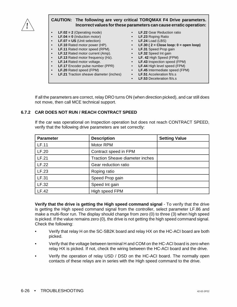
• TROUBLESHOOTING 42-02-2P226-26
CAUTION: The following are very critical TORQMAX F4 Drive parameters.Incorrect values for these parameters can cause erratic operation:
• LF.02 = 2 (Operating mode)• LF.04 = 0 (Induction motor)• LF.07 = US (Unit selection)• LF.10 Rated motor power (HP).• LF.11 Rated motor speed (RPM). • LF.12 Rated motor current (Amp).• LF.13 Rated motor frequency (Hz).• LF.14 Rated motor voltage.• LF.17 Encoder pulse number (PPR)• LF.20 Rated speed (FPM)• LF.21 Traction sheave diameter (inches)
• LF.22 Gear Reduction ratio • LF.23 Roping Ratio• LF.24 Load (LBS)• LF.30 ( 2 = Close loop: 0 = open loop)• LF.31 Speed Prop gain• LF.32 Speed Int gain• LF. 42 High Speed (FPM)• LF.43 Inspection speed (FPM)• LF.44 High level speed (FPM)• LF.45 Intermediate speed (FPM)• LF.51 Acceleration ft/s.s• LF.53 Deceleration ft/s.s
If all the parameters are correct, relay DRO turns ON (when direction picked), and car still doesnot move, then call MCE technical support.
6.7.2 CAR DOES NOT RUN / REACH CONTRACT SPEED
If the car was operational on Inspection operation but does not reach CONTRACT SPEED,verify that the following drive parameters are set correctly:
Parameter Description Setting Value
LF.11 Motor RPM
LF.20 Contract speed in FPM
LF.21 Traction Sheave diameter inches
LF.22 Gear reduction ratio
LF.23 Roping ratio
LF.31 Speed Prop gain
LF.32 Speed Int gain
LF.42 High speed FPM
Verify that the drive is getting the High speed command signal - To verify that the driveis getting the High speed command signal from the controller, select parameter LF.86 andmake a multi-floor run. The display should change from zero (0) to three (3) when high speedis picked. If the value remains zero (0), the drive is not getting the high speed command signal.Check the following:
• Verify that relay H on the SC-SB2K board and relay HX on the HC-ACI board are bothpicked.
• Verify that the voltage between terminal H and COM on the HC-ACI board is zero whenrelay HX is picked. If not, check the wiring between the HC-ACI board and the drive.
• Verify the operation of relay USD / DSD on the HC-ACI board. The normally opencontacts of these relays are in series with the High speed command to the drive.
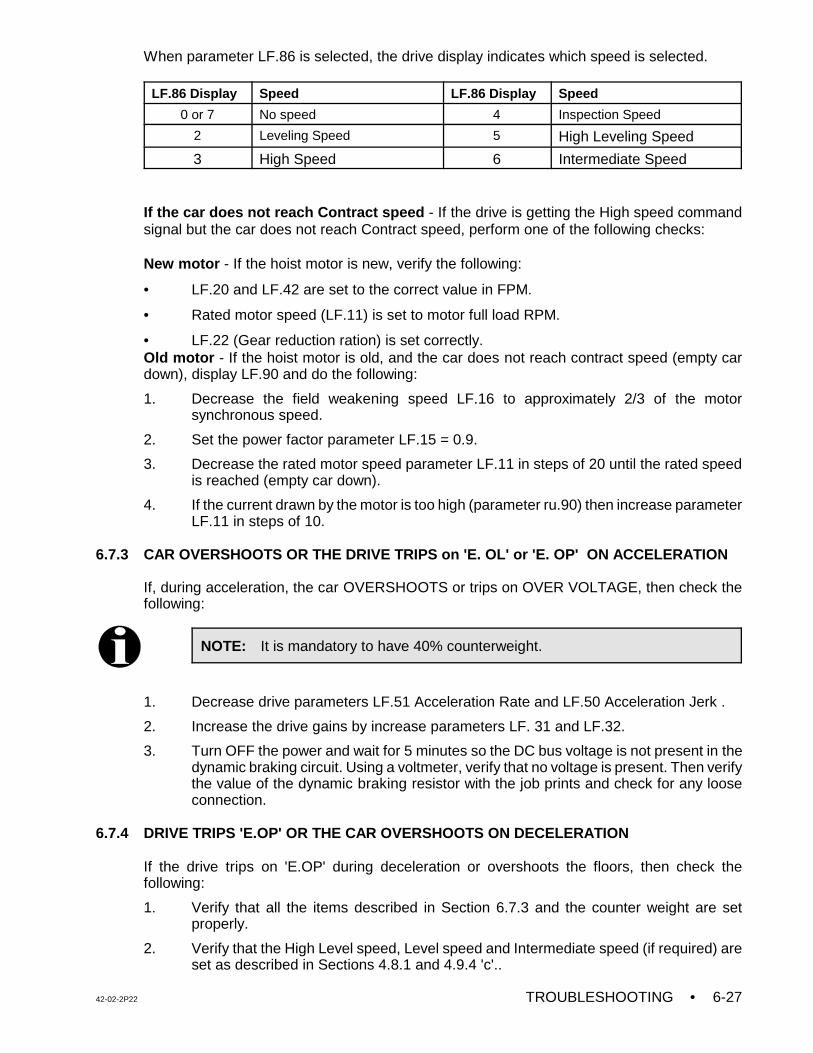
42-02-2P22 TROUBLESHOOTING • 6-27
NOTE: It is mandatory to have 40% counterweight.
When parameter LF.86 is selected, the drive display indicates which speed is selected.
LF.86 Display Speed LF.86 Display Speed
0 or 7 No speed 4 Inspection Speed
2 Leveling Speed 5 High Leveling Speed
3 High Speed 6 Intermediate Speed
If the car does not reach Contract speed - If the drive is getting the High speed commandsignal but the car does not reach Contract speed, perform one of the following checks:
New motor - If the hoist motor is new, verify the following:
• LF.20 and LF.42 are set to the correct value in FPM.
• Rated motor speed (LF.11) is set to motor full load RPM.
• LF.22 (Gear reduction ration) is set correctly.Old motor - If the hoist motor is old, and the car does not reach contract speed (empty cardown), display LF.90 and do the following:
1. Decrease the field weakening speed LF.16 to approximately 2/3 of the motorsynchronous speed.
2. Set the power factor parameter LF.15 = 0.9.
3. Decrease the rated motor speed parameter LF.11 in steps of 20 until the rated speedis reached (empty car down).
4. If the current drawn by the motor is too high (parameter ru.90) then increase parameterLF.11 in steps of 10.
6.7.3 CAR OVERSHOOTS OR THE DRIVE TRIPS on 'E. OL' or 'E. OP' ON ACCELERATION
If, during acceleration, the car OVERSHOOTS or trips on OVER VOLTAGE, then check thefollowing:
1. Decrease drive parameters LF.51 Acceleration Rate and LF.50 Acceleration Jerk .
2. Increase the drive gains by increase parameters LF. 31 and LF.32.
3. Turn OFF the power and wait for 5 minutes so the DC bus voltage is not present in thedynamic braking circuit. Using a voltmeter, verify that no voltage is present. Then verifythe value of the dynamic braking resistor with the job prints and check for any looseconnection.
6.7.4 DRIVE TRIPS 'E.OP' OR THE CAR OVERSHOOTS ON DECELERATION
If the drive trips on 'E.OP' during deceleration or overshoots the floors, then check thefollowing:
1. Verify that all the items described in Section 6.7.3 and the counter weight are setproperly.
2. Verify that the High Level speed, Level speed and Intermediate speed (if required) areset as described in Sections 4.8.1 and 4.9.4 'c'..
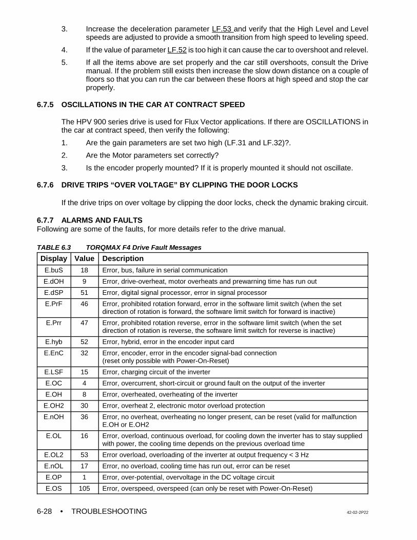
• TROUBLESHOOTING 42-02-2P226-28
3. Increase the deceleration parameter LF.53 and verify that the High Level and Levelspeeds are adjusted to provide a smooth transition from high speed to leveling speed.
4. If the value of parameter LF.52 is too high it can cause the car to overshoot and relevel.
5. If all the items above are set properly and the car still overshoots, consult the Drivemanual. If the problem still exists then increase the slow down distance on a couple offloors so that you can run the car between these floors at high speed and stop the carproperly.
6.7.5 OSCILLATIONS IN THE CAR AT CONTRACT SPEED
The HPV 900 series drive is used for Flux Vector applications. If there are OSCILLATIONS inthe car at contract speed, then verify the following:
1. Are the gain parameters are set two high (LF.31 and LF.32)?.
2. Are the Motor parameters set correctly?
3. Is the encoder properly mounted? If it is properly mounted it should not oscillate.
6.7.6 DRIVE TRIPS “OVER VOLTAGE” BY CLIPPING THE DOOR LOCKS
If the drive trips on over voltage by clipping the door locks, check the dynamic braking circuit.
6.7.7 ALARMS AND FAULTS Following are some of the faults, for more details refer to the drive manual.
TABLE 6.3 TORQMAX F4 Drive Fault Messages
Display Value Description
E.buS 18 Error, bus, failure in serial communication
E.dOH 9 Error, drive-overheat, motor overheats and prewarning time has run out
E.dSP 51 Error, digital signal processor, error in signal processor
E.PrF 46 Error, prohibited rotation forward, error in the software limit switch (when the setdirection of rotation is forward, the software limit switch for forward is inactive)
E.Prr 47 Error, prohibited rotation reverse, error in the software limit switch (when the setdirection of rotation is reverse, the software limit switch for reverse is inactive)
E.hyb 52 Error, hybrid, error in the encoder input card
E.EnC 32 Error, encoder, error in the encoder signal-bad connection(reset only possible with Power-On-Reset)
E.LSF 15 Error, charging circuit of the inverter
E.OC 4 Error, overcurrent, short-circuit or ground fault on the output of the inverter
E.OH 8 Error, overheated, overheating of the inverter
E.OH2 30 Error, overheat 2, electronic motor overload protection
E.nOH 36 Error, no overheat, overheating no longer present, can be reset (valid for malfunctionE.OH or E.OH2
E.OL 16 Error, overload, continuous overload, for cooling down the inverter has to stay suppliedwith power, the cooling time depends on the previous overload time
E.OL2 53 Error overload, overloading of the inverter at output frequency < 3 Hz
E.nOL 17 Error, no overload, cooling time has run out, error can be reset
E.OP 1 Error, over-potential, overvoltage in the DC voltage circuit
E.OS 105 Error, overspeed, overspeed (can only be reset with Power-On-Reset)
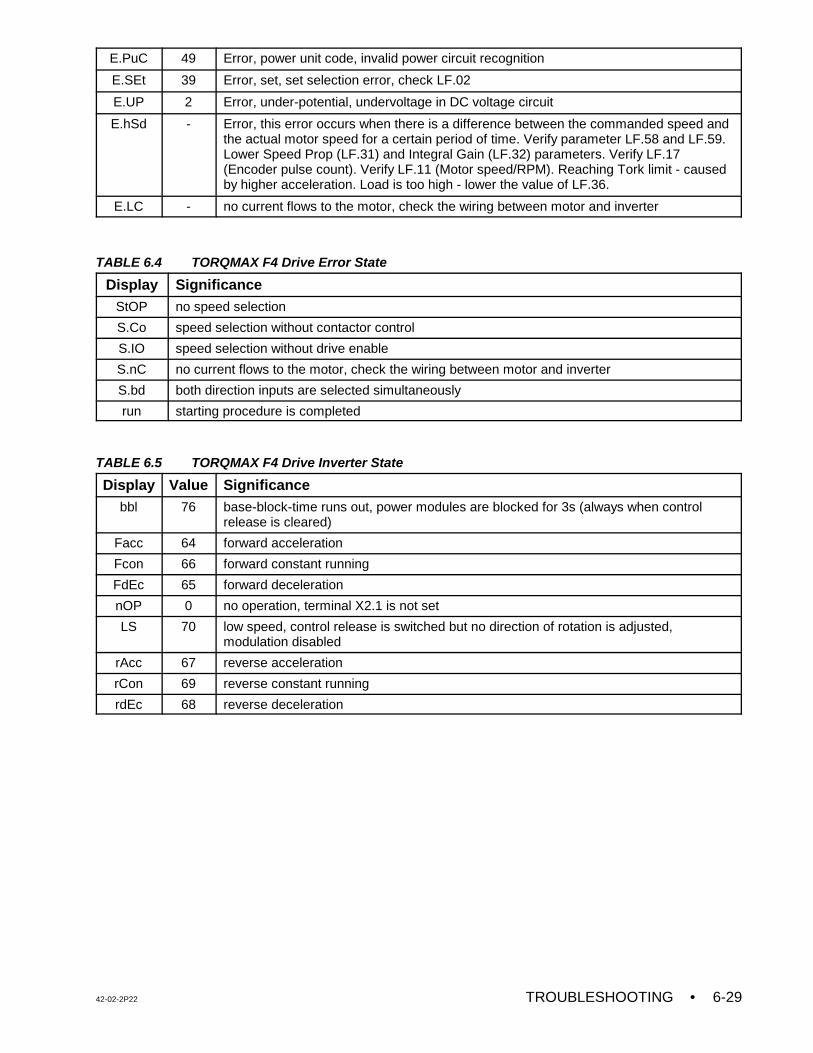
42-02-2P22 TROUBLESHOOTING • 6-29
E.PuC 49 Error, power unit code, invalid power circuit recognition
E.SEt 39 Error, set, set selection error, check LF.02
E.UP 2 Error, under-potential, undervoltage in DC voltage circuit
E.hSd - Error, this error occurs when there is a difference between the commanded speed andthe actual motor speed for a certain period of time. Verify parameter LF.58 and LF.59.Lower Speed Prop (LF.31) and Integral Gain (LF.32) parameters. Verify LF.17(Encoder pulse count). Verify LF.11 (Motor speed/RPM). Reaching Tork limit - causedby higher acceleration. Load is too high - lower the value of LF.36.
E.LC - no current flows to the motor, check the wiring between motor and inverter
TABLE 6.4 TORQMAX F4 Drive Error State
Display SignificanceStOP no speed selection
S.Co speed selection without contactor control
S.IO speed selection without drive enable
S.nC no current flows to the motor, check the wiring between motor and inverter
S.bd both direction inputs are selected simultaneously
run starting procedure is completed
TABLE 6.5 TORQMAX F4 Drive Inverter State
Display Value Significancebbl 76 base-block-time runs out, power modules are blocked for 3s (always when control
release is cleared)
Facc 64 forward acceleration
Fcon 66 forward constant running
FdEc 65 forward deceleration
nOP 0 no operation, terminal X2.1 is not set
LS 70 low speed, control release is switched but no direction of rotation is adjusted,modulation disabled
rAcc 67 reverse acceleration
rCon 69 reverse constant running
rdEc 68 reverse deceleration
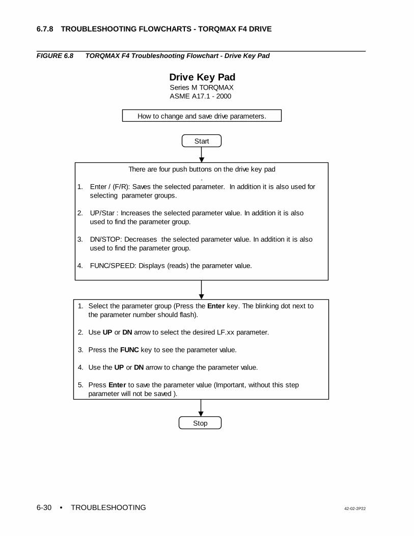
• TROUBLESHOOTING 42-02-2P226-30
Start
There are four push buttons on the drive key pad.
1. Enter / (F/R): Saves the selected parameter. In addition it is also used for selecting parameter groups.
2. UP/Star : Increases the selected parameter value. In addition it is also used to find the parameter group.
3. DN/STOP: Decreases the selected parameter value. In addition it is also used to find the parameter group.
4. FUNC/SPEED: Displays (reads) the parameter value.
1. Select the parameter group (Press the Enter key. The blinking dot next to the parameter number should flash). 2. Use UP or DN arrow to select the desired LF.xx parameter.
3. Press the FUNC key to see the parameter value.
4. Use the UP or DN arrow to change the parameter value. 5. Press Enter to save the parameter value (Important, without this step parameter will not be saved ).
Stop
Drive Key PadSeries M TORQMAXASME A17.1 - 2000
How to change and save drive parameters.
6.7.8 TROUBLESHOOTING FLOWCHARTS - TORQMAX F4 DRIVE
FIGURE 6.8 TORQMAX F4 Troubleshooting Flowchart - Drive Key Pad
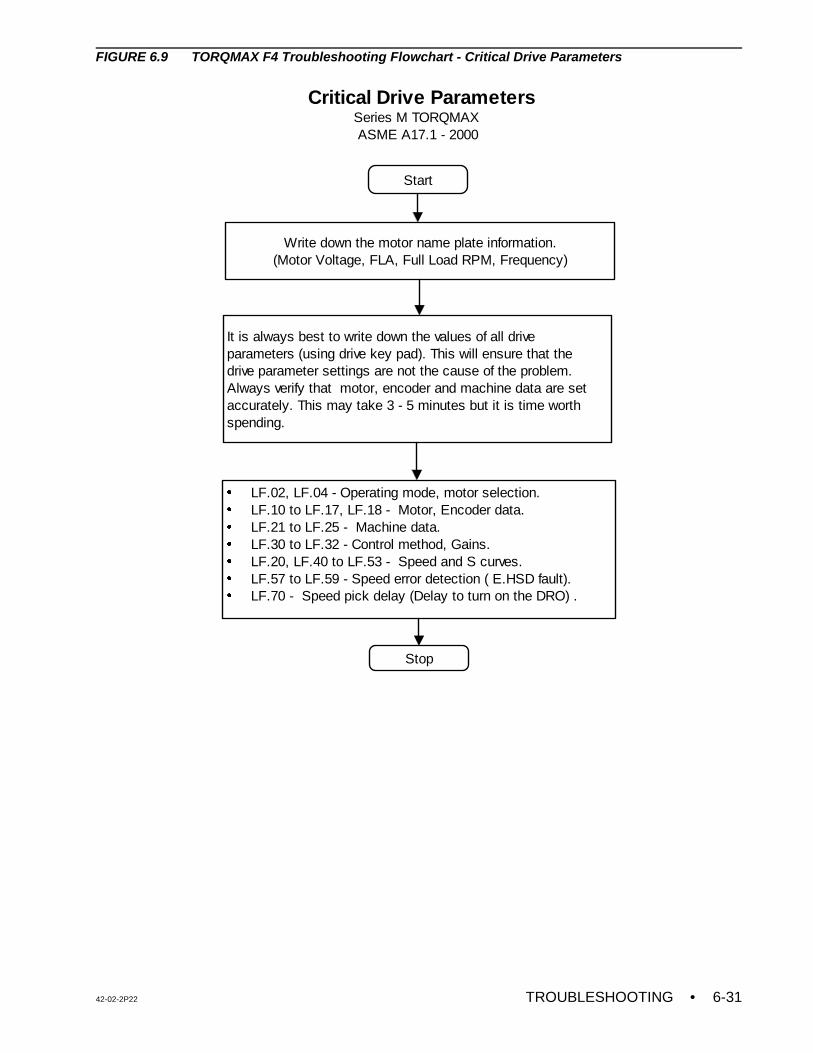
42-02-2P22 TROUBLESHOOTING • 6-31
Start
Write down the motor name plate information.(Motor Voltage, FLA, Full Load RPM, Frequency)
It is always best to write down the values of all drive parameters (using drive key pad). This will ensure that the drive parameter settings are not the cause of the problem. Always verify that motor, encoder and machine data are set accurately. This may take 3 - 5 minutes but it is time worth spending.
LF.02, LF.04 - Operating mode, motor selection.LF.10 to LF.17, LF.18 - Motor, Encoder data.LF.21 to LF.25 - Machine data.LF.30 to LF.32 - Control method, Gains.LF.20, LF.40 to LF.53 - Speed and S curves.LF.57 to LF.59 - Speed error detection ( E.HSD fault). LF.70 - Speed pick delay (Delay to turn on the DRO) .
Stop
Critical Drive Parameters Series M TORQMAX ASME A17.1 - 2000
FIGURE 6.9 TORQMAX F4 Troubleshooting Flowchart - Critical Drive Parameters
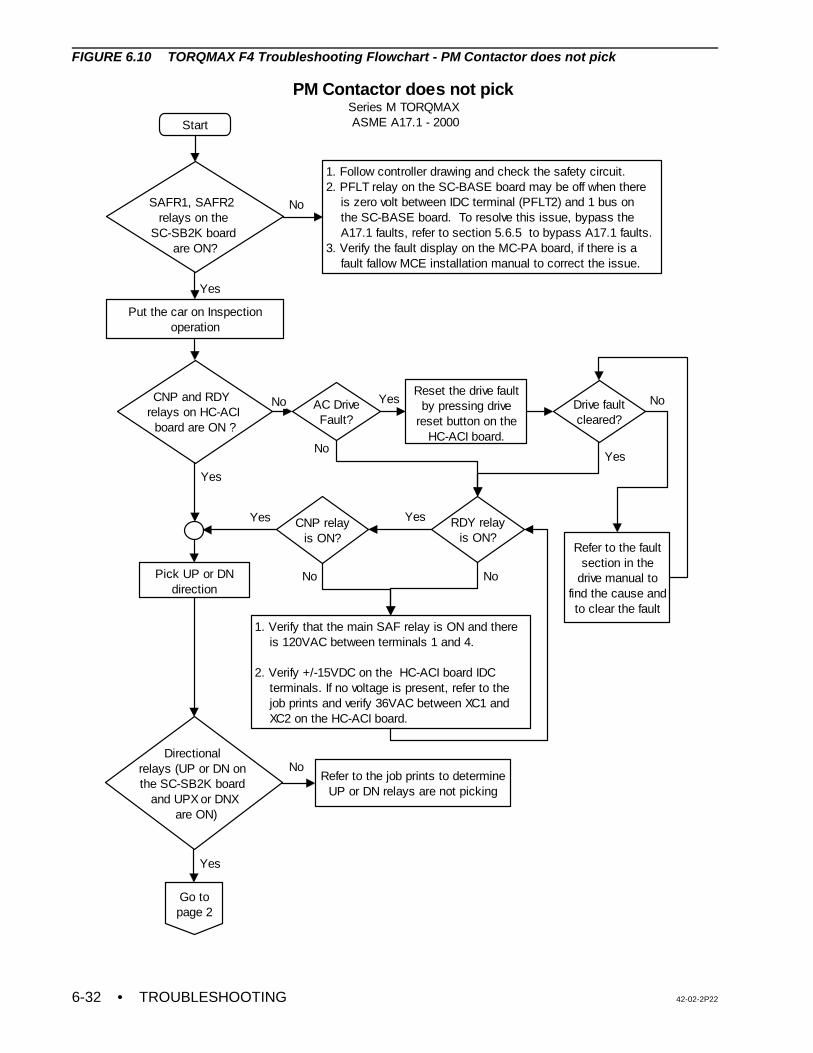
• TROUBLESHOOTING 42-02-2P226-32
Start
Put the car on Inspection operation
CNP and RDY relays on HC-ACI
board are ON ?
Reset the drive fault by pressing drive
reset button on the HC-ACI board.
CNP relayis ON?
Pick UP or DN direction
Directional relays (UP or DN on the SC-SB2K board
and UPX or DNX are ON)
Refer to the fault section in the
drive manual to find the cause and to clear the fault
Yes
Refer to the job prints to determine UP or DN relays are not picking
No
PM Contactor does not pick Series M TORQMAX ASME A17.1 - 2000
SAFR1, SAFR2 relays on the
SC-SB2K board are ON?
1. Follow controller drawing and check the safety circuit.2. PFLT relay on the SC-BASE board may be off when there is zero volt between IDC terminal (PFLT2) and 1 bus on the SC-BASE board. To resolve this issue, bypass the A17.1 faults, refer to section 5.6.5 to bypass A17.1 faults.3. Verify the fault display on the MC-PA board, if there is a fault fallow MCE installation manual to correct the issue.
No
Yes
AC DriveFault?
No Yes
RDY relayis ON?
1. Verify that the main SAF relay is ON and there is 120VAC between terminals 1 and 4.
2. Verify +/-15VDC on the HC-ACI board IDC terminals. If no voltage is present, refer to the job prints and verify 36VAC between XC1 and XC2 on the HC-ACI board.
Drive faultcleared?
No
No
Go to page 2
Yes
Yes
YesYes
No No
FIGURE 6.10 TORQMAX F4 Troubleshooting Flowchart - PM Contactor does not pick
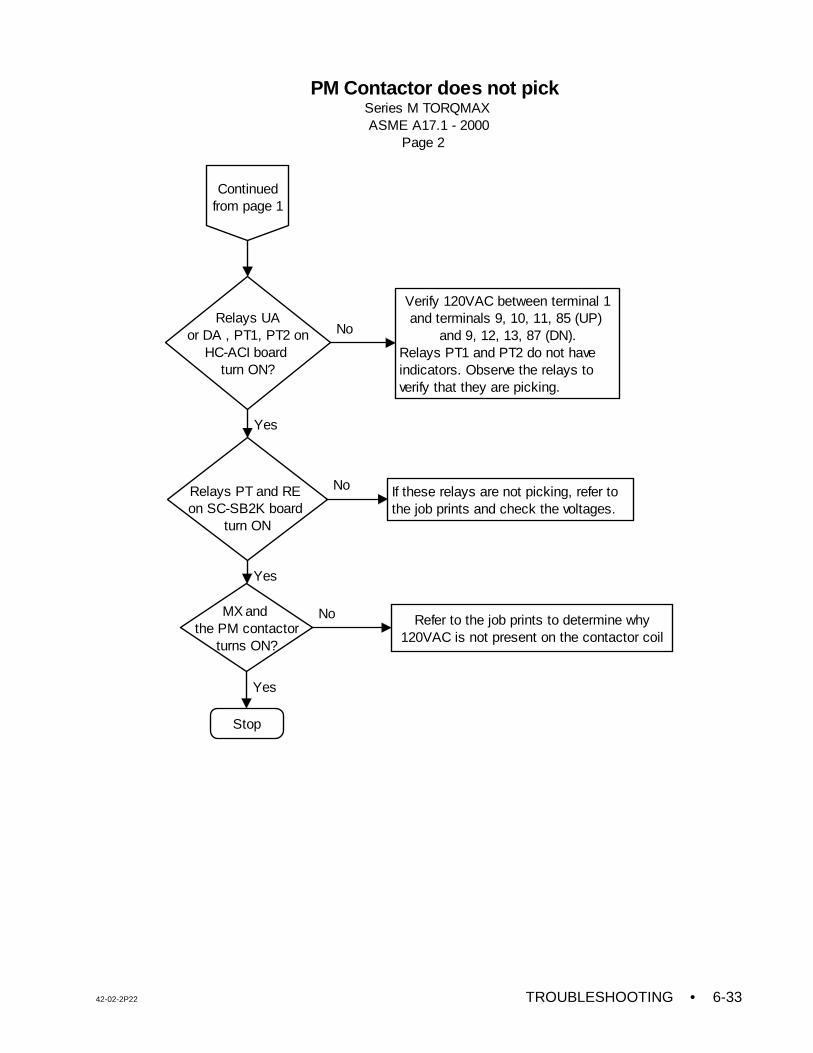
42-02-2P22 TROUBLESHOOTING • 6-33
Relays PT and RE on SC-SB2K board
turn ON
MX and the PM contactor
turns ON?
Verify 120VAC between terminal 1 and terminals 9, 10, 11, 85 (UP)
and 9, 12, 13, 87 (DN).Relays PT1 and PT2 do not have indicators. Observe the relays to verify that they are picking.
Relays UAor DA , PT1, PT2 on
HC-ACI board turn ON?
Refer to the job prints to determine why 120VAC is not present on the contactor coil
No
Yes
Yes
Stop
No
Yes
If these relays are not picking, refer to the job prints and check the voltages.
No
Continued from page 1
PM Contactor does not pick Series M TORQMAX ASME A17.1 - 2000 Page 2
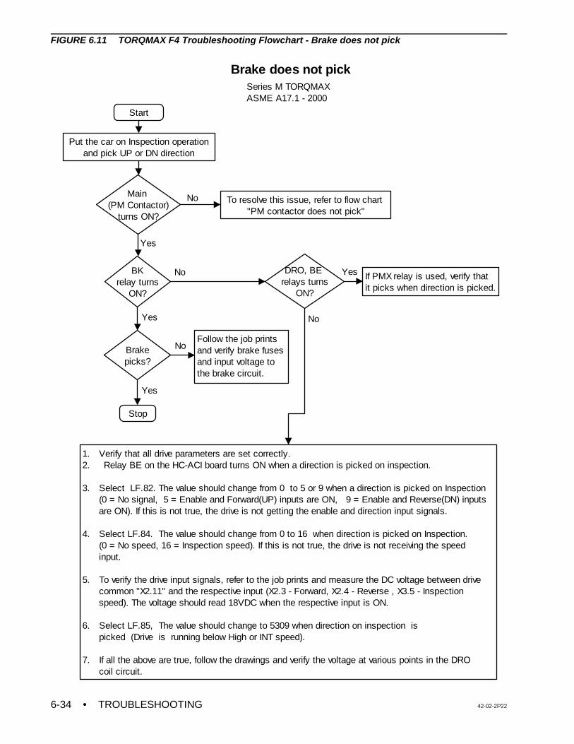
• TROUBLESHOOTING 42-02-2P226-34
Start
Put the car on Inspection operation and pick UP or DN direction
Main (PM Contactor)
turns ON?
To resolve this issue, refer to flow chart "PM contactor does not pick"
BKrelay turns
ON?
No
Yes
DRO, BE relays turns
ON?
No If PMX relay is used, verify that it picks when direction is picked.
1. Verify that all drive parameters are set correctly. 2. Relay BE on the HC-ACI board turns ON when a direction is picked on inspection. 3. Select LF.82. The value should change from 0 to 5 or 9 when a direction is picked on Inspection (0 = No signal, 5 = Enable and Forward(UP) inputs are ON, 9 = Enable and Reverse(DN) inputs are ON). If this is not true, the drive is not getting the enable and direction input signals. 4. Select LF.84. The value should change from 0 to 16 when direction is picked on Inspection. (0 = No speed, 16 = Inspection speed). If this is not true, the drive is not receiving the speed input. 5. To verify the drive input signals, refer to the job prints and measure the DC voltage between drive common "X2.11" and the respective input (X2.3 - Forward, X2.4 - Reverse , X3.5 - Inspection speed). The voltage should read 18VDC when the respective input is ON. 6. Select LF.85, The value should change to 5309 when direction on inspection is picked (Drive is running below High or INT speed).
7. If all the above are true, follow the drawings and verify the voltage at various points in the DRO coil circuit.
No
Yes
Stop
Brake does not pickSeries M TORQMAXASME A17.1 - 2000
Brakepicks?
Yes
Follow the job prints and verify brake fuses and input voltage to the brake circuit.
Yes
No
FIGURE 6.11 TORQMAX F4 Troubleshooting Flowchart - Brake does not pick
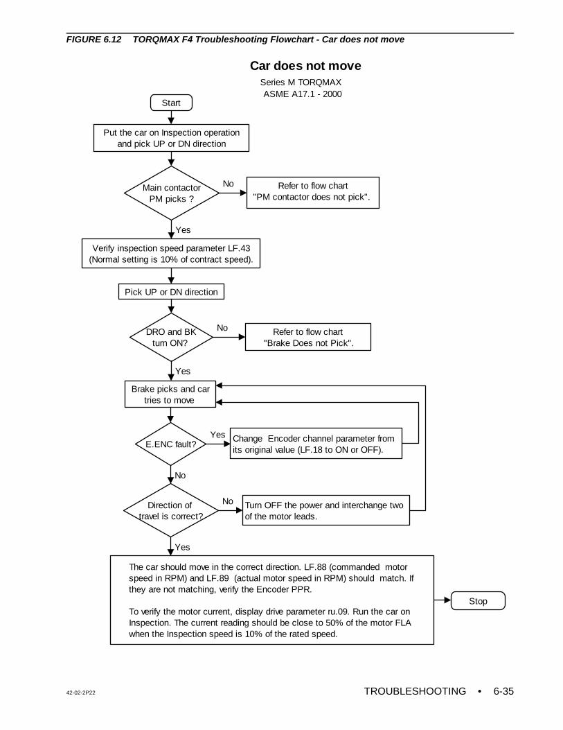
42-02-2P22 TROUBLESHOOTING • 6-35
Start
Put the car on Inspection operation and pick UP or DN direction
Main contactorPM picks ?
Refer to flow chart "PM contactor does not pick".
No
Verify inspection speed parameter LF.43 (Normal setting is 10% of contract speed).
Yes
DRO and BKturn ON?
Refer to flow chart"Brake Does not Pick".
No
Brake picks and car tries to move
E.ENC fault?
Yes
Change Encoder channel parameter from its original value (LF.18 to ON or OFF).
Direction of travel is correct?
No
Yes
Turn OFF the power and interchange two of the motor leads.
No
The car should move in the correct direction. LF.88 (commanded motor speed in RPM) and LF.89 (actual motor speed in RPM) should match. If they are not matching, verify the Encoder PPR.
To verify the motor current, display drive parameter ru.09. Run the car on Inspection. The current reading should be close to 50% of the motor FLA when the Inspection speed is 10% of the rated speed.
Yes
Stop
Car does not move Series M TORQMAX ASME A17.1 - 2000
Pick UP or DN direction
FIGURE 6.12 TORQMAX F4 Troubleshooting Flowchart - Car does not move
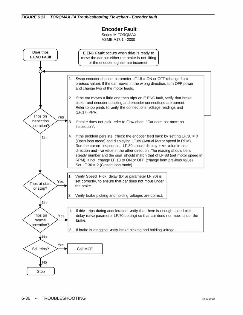
• TROUBLESHOOTING 42-02-2P226-36
Drive tripsE.ENC Fault
Trips onInspection operation?
Trips onNormal
operation?
Trips at startor stop?
Still trips?
1. If drive trips during acceleration, verify that there is enough speed pick delay (drive parameter LF.70 setting) so that car does not move under the brake.
2. If brake is dragging, verify brake picking and holding voltage.
1. Verify Speed Pick delay (Drive parameter LF.70) is set correctly, to ensure that car does not move under the brake.
2. Verify brake picking and holding voltages are correct.
Call MCE
Stop
Yes
Yes
No
Yes
1. Swap encoder channel parameter LF.18 = ON or OFF (change from previous value). If the car moves in the wrong direction, turn OFF power and change two of the motor leads.
2. If the car moves a little and then trips on E.ENC fault, verify that brake picks, and encoder coupling and encoder connections are correct. Refer to job prints to verify the connections, voltage readings and (LF.17) PPR.
3. If brake does not pick, refer to Flow chart "Car does not move on Inspection". 4. If the problem persists, check the encoder feed back by setting LF.30 = 0 (Open loop mode) and displaying LF.89 (Actual Motor speed in RPM). Run the car on Inspection. LF.89 should display + ve value in one direction and - ve value in the other direction. The reading should be a steady number and the sign should match that of LF.88 (set motor speed in RPM). If not, change LF.18 to ON or OFF (change from previous value). Set LF.30 = 2 (Closed loop mode).
Yes
Encoder FaultSeries M TORQMAXASME A17.1 - 2000
E.ENC Fault occurs when drive is ready to move the car but either the brake is not lifting
or the encoder signals are incorrect.
No
No
No
FIGURE 6.13 TORQMAX F4 Troubleshooting Flowchart - Encoder fault
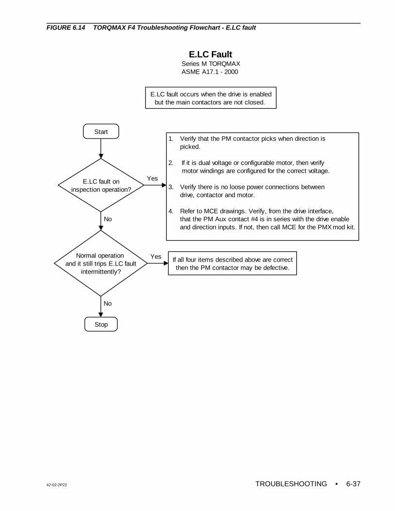
42-02-2P22 TROUBLESHOOTING • 6-37
Start
E.LC fault oninspection operation?
1. Verify that the PM contactor picks when direction is picked.
2. If it is dual voltage or configurable motor, then verify motor windings are configured for the correct voltage. 3. Verify there is no loose power connections between drive, contactor and motor.
4. Refer to MCE drawings. Verify, from the drive interface, that the PM Aux contact #4 is in series with the drive enable and direction inputs. If not, then call MCE for the PMX mod kit.
Normal operation and it still trips E.LC fault
intermittently?
Stop
No
If all four items described above are correct then the PM contactor may be defective.
Yes
No
Yes
E.LC FaultSeries M TORQMAXASME A17.1 - 2000
E.LC fault occurs when the drive is enabled but the main contactors are not closed.
FIGURE 6.14 TORQMAX F4 Troubleshooting Flowchart - E.LC fault
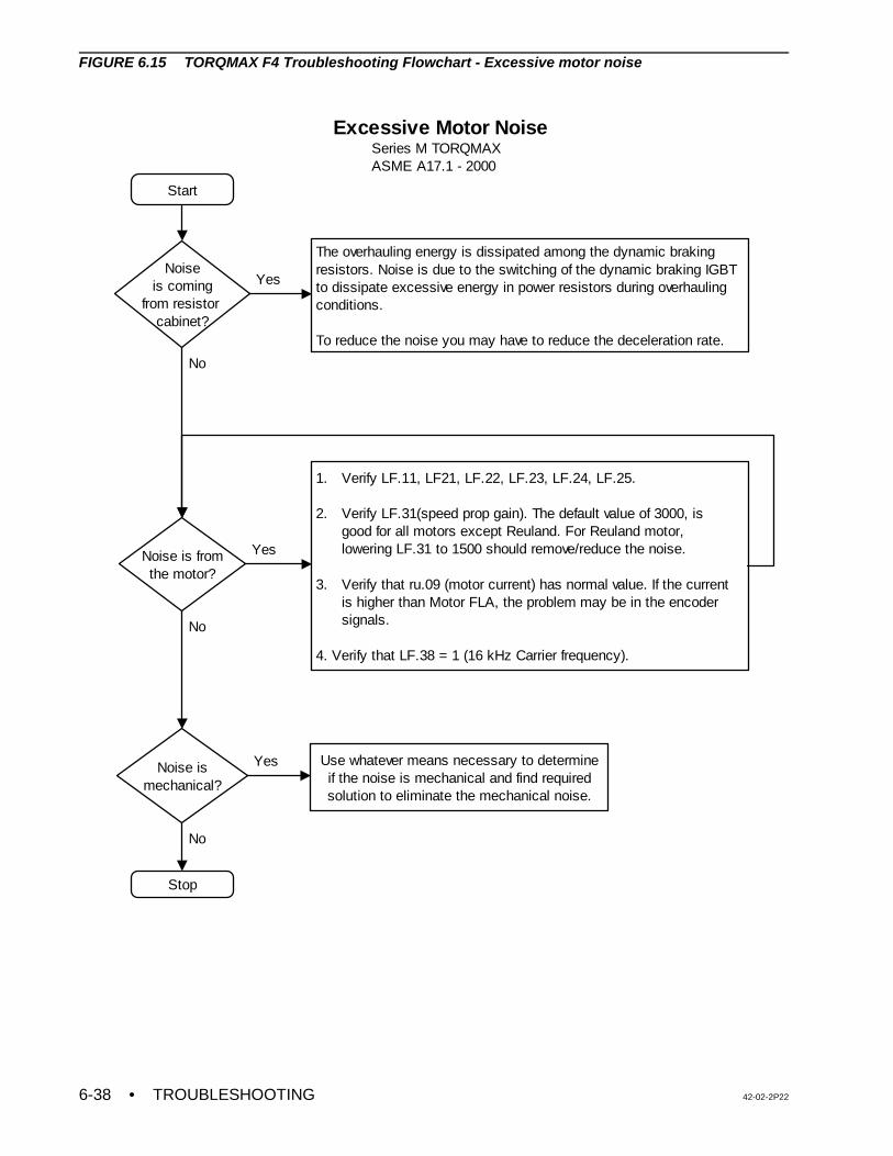
• TROUBLESHOOTING 42-02-2P226-38
Start
Noise ismechanical?
Use whatever means necessary to determine if the noise is mechanical and find required solution to eliminate the mechanical noise.
Noiseis coming
from resistor cabinet?
The overhauling energy is dissipated among the dynamic braking resistors. Noise is due to the switching of the dynamic braking IGBT to dissipate excessive energy in power resistors during overhauling conditions.
To reduce the noise you may have to reduce the deceleration rate.
Noise is fromthe motor?
Yes
No
Yes
1. Verify LF.11, LF21, LF.22, LF.23, LF.24, LF.25.
2. Verify LF.31(speed prop gain). The default value of 3000, is good for all motors except Reuland. For Reuland motor, lowering LF.31 to 1500 should remove/reduce the noise.
3. Verify that ru.09 (motor current) has normal value. If the current is higher than Motor FLA, the problem may be in the encoder signals.
4. Verify that LF.38 = 1 (16 kHz Carrier frequency).
Stop
Yes
No
No
Excessive Motor Noise Series M TORQMAX ASME A17.1 - 2000
FIGURE 6.15 TORQMAX F4 Troubleshooting Flowchart - Excessive motor noise
42-02-2P22 TROUBLESHOOTING • 6-39
NOTE: The drive software has been modified for this application. Some of theparameters in the parameter sheet are different and are not available in thedrive manual. If a drive has been replaced in the field, all of the driveparameters should be entered manually and should be verified accordingto the parameter sheet shipped with the controller.
NOTE: Many of the safety relays that populate the main PC boards (SC-SB2K andSC-BASE) are soldered to the board, therefore it will be necessary toreplace the entire board when any relay fails to operate as intended.
6.8 TROUBLESHOOTING THE YASKSWA F7 AC DRIVE
The VFAC drive’s digital operator display must read as follows during power up: Frequencyreference U1-01=0. If any fault or problem is detected, then turn off the power and refer to theAlarms and Fault Displays section of the Yaskawa F7 AC Drive Manual.
6.8.1 CAR DOES NOT MOVE ON INSPECTION
• Pick or Picked = relay energized• Drop or dropped = relay de-energized
If the car does not move on INSPECTION, check the following:
1. Relays SAFR1 and SAFR2 will drop and pick back up at the end of every run, but onlyif the code mandated “cycle tests” function as required. This means that after every runthe critical relays are dropped out to ensure that no contacts have welded. If a failureof the relays or overspeed logic is detected both SAFR1 and SAFR2 will not be allowedto pick. If this is the case, inspect the message scrolling on the MC-PCA display todetermine which section of the hardware has failed.
PFLT Relay - The PFLT relay is mounted on the SC-BASE-x board and has a singlenormally open contact in the safety string, immediately following IDC20 and before theOL contact which feeds power to relays SAFR1 and SAFR2. The normally open contactof the PFLT relay is directly monitored by the MC-PCA Main Processor through thePFLT input from and through the SC-HDIO board on IDC ASI1. The PFLT relay shouldremain energized during Normal operation. This relay drops and causes an EmergencyShutdown and stops the car under the following conditions: ILO, ETS and contractoverspeed. The PFLT relay also turns OFF during PLD1 cycle testing.
2. Verify that contactors PM (Main) and BK (Brake) pick when the direction relays, U andD, are picked). If PM and BK do not pick, check the related circuit (MB) as shown in thecontroller drawings. Check for any fault that is displayed on the drive keypad before andafter picking the direction on Inspection. When the direction is picked on Inspection,relays RE and CHDT on the SC-SB2K board should be picked. Also relays PT1 andPT2 on the HC-ACI board should be picked. If these relays are not picked, check for120VAC on terminals 9, 10,12 and 20 on the SC-SB2K Main Safety Relay Board. Ifthere is no voltage on these terminals, refer to the controller drawings to find theproblem. Note that relays SAFR1, SAFR2, CNP and RDY should also be picked.
3. Verify that the drive receives the direction enable and inspection speed commandsignals from the (HC-ACI) board. The drive key pad should display the commanded
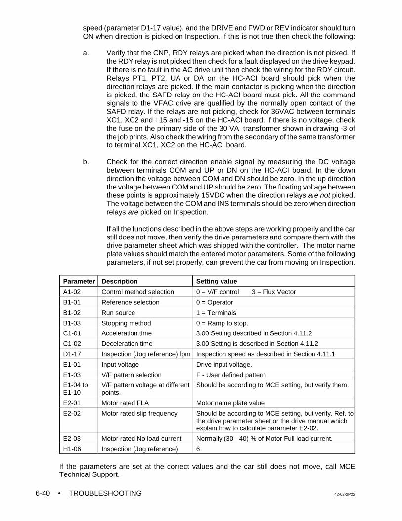
• TROUBLESHOOTING 42-02-2P226-40
speed (parameter D1-17 value), and the DRIVE and FWD or REV indicator should turnON when direction is picked on Inspection. If this is not true then check the following:
a. Verify that the CNP, RDY relays are picked when the direction is not picked. Ifthe RDY relay is not picked then check for a fault displayed on the drive keypad.If there is no fault in the AC drive unit then check the wiring for the RDY circuit.Relays PT1, PT2, UA or DA on the HC-ACI board should pick when thedirection relays are picked. If the main contactor is picking when the directionis picked, the SAFD relay on the HC-ACI board must pick. All the commandsignals to the VFAC drive are qualified by the normally open contact of theSAFD relay. If the relays are not picking, check for 36VAC between terminalsXC1, XC2 and +15 and -15 on the HC-ACI board. If there is no voltage, checkthe fuse on the primary side of the 30 VA transformer shown in drawing -3 ofthe job prints. Also check the wiring from the secondary of the same transformerto terminal XC1, XC2 on the HC-ACI board.
b. Check for the correct direction enable signal by measuring the DC voltagebetween terminals COM and UP or DN on the HC-ACI board. In the downdirection the voltage between COM and DN should be zero. In the up directionthe voltage between COM and UP should be zero. The floating voltage betweenthese points is approximately 15VDC when the direction relays are not picked.The voltage between the COM and INS terminals should be zero when directionrelays are picked on Inspection.
If all the functions described in the above steps are working properly and the carstill does not move, then verify the drive parameters and compare them with thedrive parameter sheet which was shipped with the controller. The motor nameplate values should match the entered motor parameters. Some of the followingparameters, if not set properly, can prevent the car from moving on Inspection.
Parameter Description Setting value
A1-02 Control method selection 0 = V/F control 3 = Flux Vector
B1-01 Reference selection 0 = Operator
B1-02 Run source 1 = Terminals
B1-03 Stopping method 0 = Ramp to stop.
C1-01 Acceleration time 3.00 Setting described in Section 4.11.2
C1-02 Deceleration time 3.00 Setting is described in Section 4.11.2
D1-17 Inspection (Jog reference) fpm Inspection speed as described in Section 4.11.1
E1-01 Input voltage Drive input voltage.
E1-03 V/F pattern selection F - User defined pattern
E1-04 toE1-10
V/F pattern voltage at differentpoints.
Should be according to MCE setting, but verify them.
E2-01 Motor rated FLA Motor name plate value
E2-02 Motor rated slip frequency Should be according to MCE setting, but verify. Ref. tothe drive parameter sheet or the drive manual whichexplain how to calculate parameter E2-02.
E2-03 Motor rated No load current Normally (30 - 40) % of Motor Full load current.
H1-06 Inspection (Jog reference) 6
If the parameters are set at the correct values and the car still does not move, call MCETechnical Support.
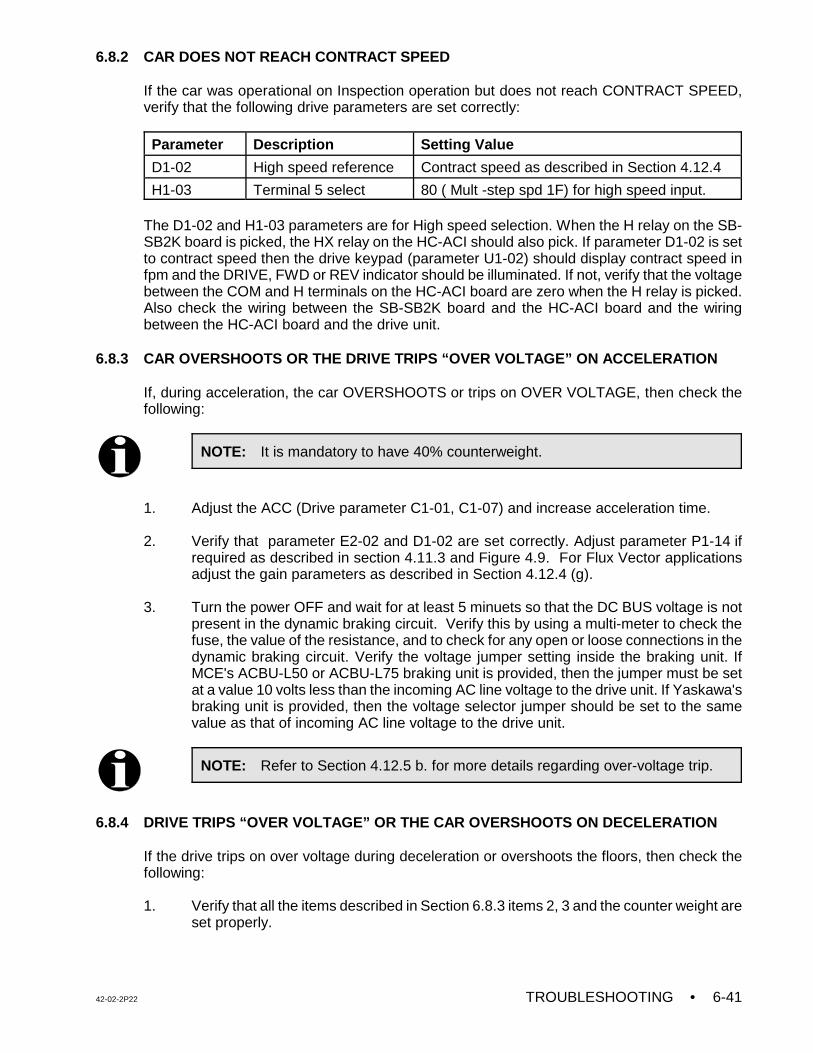
42-02-2P22 TROUBLESHOOTING • 6-41
NOTE: It is mandatory to have 40% counterweight.
NOTE: Refer to Section 4.12.5 b. for more details regarding over-voltage trip.
6.8.2 CAR DOES NOT REACH CONTRACT SPEED
If the car was operational on Inspection operation but does not reach CONTRACT SPEED,verify that the following drive parameters are set correctly:
Parameter Description Setting Value
D1-02 High speed reference Contract speed as described in Section 4.12.4
H1-03 Terminal 5 select 80 ( Mult -step spd 1F) for high speed input.
The D1-02 and H1-03 parameters are for High speed selection. When the H relay on the SB-SB2K board is picked, the HX relay on the HC-ACI should also pick. If parameter D1-02 is setto contract speed then the drive keypad (parameter U1-02) should display contract speed infpm and the DRIVE, FWD or REV indicator should be illuminated. If not, verify that the voltagebetween the COM and H terminals on the HC-ACI board are zero when the H relay is picked.Also check the wiring between the SB-SB2K board and the HC-ACI board and the wiringbetween the HC-ACI board and the drive unit.
6.8.3 CAR OVERSHOOTS OR THE DRIVE TRIPS “OVER VOLTAGE” ON ACCELERATION
If, during acceleration, the car OVERSHOOTS or trips on OVER VOLTAGE, then check thefollowing:
1. Adjust the ACC (Drive parameter C1-01, C1-07) and increase acceleration time.
2. Verify that parameter E2-02 and D1-02 are set correctly. Adjust parameter P1-14 ifrequired as described in section 4.11.3 and Figure 4.9. For Flux Vector applicationsadjust the gain parameters as described in Section 4.12.4 (g).
3. Turn the power OFF and wait for at least 5 minuets so that the DC BUS voltage is notpresent in the dynamic braking circuit. Verify this by using a multi-meter to check thefuse, the value of the resistance, and to check for any open or loose connections in thedynamic braking circuit. Verify the voltage jumper setting inside the braking unit. IfMCE's ACBU-L50 or ACBU-L75 braking unit is provided, then the jumper must be setat a value 10 volts less than the incoming AC line voltage to the drive unit. If Yaskawa'sbraking unit is provided, then the voltage selector jumper should be set to the samevalue as that of incoming AC line voltage to the drive unit.
6.8.4 DRIVE TRIPS “OVER VOLTAGE” OR THE CAR OVERSHOOTS ON DECELERATION
If the drive trips on over voltage during deceleration or overshoots the floors, then check thefollowing:
1. Verify that all the items described in Section 6.8.3 items 2, 3 and the counter weight areset properly.
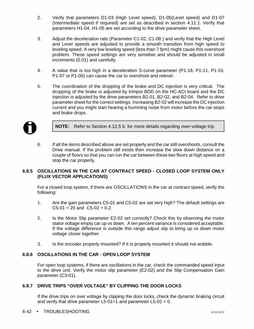
• TROUBLESHOOTING 42-02-2P226-42
NOTE: Refer to Section 4.12.5 b. for more details regarding over-voltage trip.
2. Verify that parameters D1-03 (High Level speed), D1-05(Level speed) and D1-07(Intermediate speed if required) are set as described in section 4.11.1. Verify thatparameters H1-04, H1-05 are set according to the drive parameter sheet.
3. Adjust the deceleration rate (Parameter C1-02, C1-08 ) and verify that the High Leveland Level speeds are adjusted to provide a smooth transition from high speed toleveling speed. A very low leveling speed (less than 7 fpm) might cause this overshootproblem. These speed settings are very sensitive and should be adjusted in smallincrements (0.01) and carefully.
4. A value that is too high in a deceleration S-curve parameter (P1-18, P1-11, P1-10,P1-07 or P1-06) can cause the car to overshoot and relevel.
5. The coordination of the dropping of the brake and DC injection is very critical. Thedropping of the brake is adjusted by trimpot BDD on the HC-ACI board and the DCinjection is adjusted by the drive parameters B2-01, B2-02, and B2-04. Refer to driveparameter sheet for the correct settings. Increasing B2-02 will increase the DC injectioncurrent and you might start hearing a humming noise from motor before the car stopsand brake drops.
6. If all the items described above are set properly and the car still overshoots, consult theDrive manual. If the problem still exists then increase the slow down distance on acouple of floors so that you can run the car between these two floors at high speed andstop the car properly.
6.8.5 OSCILLATIONS IN THE CAR AT CONTRACT SPEED - CLOSED LOOP SYSTEM ONLY(FLUX VECTOR APPLICATIONS)
For a closed loop system, if there are OSCILLATIONS in the car at contract speed, verify thefollowing:
1. Are the gain parameters C5-01 and C5-02 are set very high? The default settings areC5-01 = 20 and C5-02 = 0.2.
2. Is the Motor Slip parameter E2-02 set correctly? Check this by observing the motor
stator voltage empty car up vs down. A ten percent variance is considered acceptable.If the voltage difference is outside this range adjust slip to bring up vs down motorvoltage closer together.
3. Is the encoder properly mounted? If it is properly mounted it should not wobble.
6.8.6 OSCILLATIONS IN THE CAR - OPEN LOOP SYSTEM
For open loop systems, if there are oscillations in the car, check the commanded speed inputto the drive unit. Verify the motor slip parameter (E2-02) and the Slip Compensation Gainparameter (C3-01).
6.8.7 DRIVE TRIPS “OVER VOLTAGE” BY CLIPPING THE DOOR LOCKS
If the drive trips on over voltage by clipping the door locks, check the dynamic braking circuitand verify that drive parameter L5-01=1 and parameter L5-02 = 0.
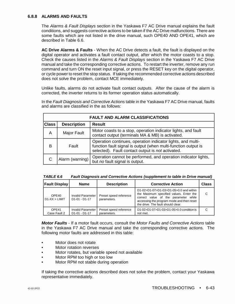
42-02-2P22 TROUBLESHOOTING • 6-43
6.8.8 ALARMS AND FAULTS
The Alarms & Fault Displays section in the Yaskawa F7 AC Drive manual explains the faultconditions, and suggests corrective actions to be taken if the AC Drive malfunctions. There aresome faults which are not listed in the drive manual, such OPE40 AND OPE41, which aredescribed in Table 6.6.
AC Drive Alarms & Faults - When the AC Drive detects a fault, the fault is displayed on thedigital operator and activates a fault contact output, after which the motor coasts to a stop.Check the causes listed in the Alarms & Fault Displays section in the Yaskawa F7 AC Drivemanual and take the corresponding corrective actions. To restart the inverter, remove any runcommand and turn ON the reset input signal, or press the RESET key on the digital operator,or cycle power to reset the stop status. If taking the recommended corrective actions describeddoes not solve the problem, contact MCE immediately.
Unlike faults, alarms do not activate fault contact outputs. After the cause of the alarm iscorrected, the inverter returns to its former operation status automatically.
In the Fault Diagnosis and Corrective Actions table in the Yaskawa F7 AC Drive manual, faultsand alarms are classified in the as follows:
FAULT AND ALARM CLASSIFICATIONS
Class Description Result
A Major Fault Motor coasts to a stop, operation indicator lights, and faultcontact output (terminals MA & MB) is activated.
B FaultOperation continues, operation indicator lights, and multi-function fault signal is output (when multi-function output isselected). Fault contact output is not activated.
C Alarm (warning) Operation cannot be performed, and operation indicator lights,but no fault signal is output.
TABLE 6.6 Fault Diagnosis and Corrective Actions (supplement to table in Drive manual)
Fault Display Name Description Corrective Action Class
OPE40D1-XX > LIMIT
Invalid ParameterD1-01 - D1-17
Preset speed referenceparameters.
D1-02>D1-07>D1-03>D1-05>0.0 and withinthe Maximum specified values. Enter thecorrect value of the parameter whileaccessing the program mode and then resetthe drive. The fault should clear.
C
OPE41Case Fault 2
Invalid ParameterD1-01 - D1-17
Preset speed referenceparameters.
D1-02>D1-07>D1-03>D1-05>0.0 condition isnot met.
C
Motor Faults - If a motor fault occurs, consult the Motor Faults and Corrective Actions tablein the Yaskawa F7 AC Drive manual and take the corresponding corrective actions. Thefollowing motor faults are addressed in this table:
• Motor does not rotate• Motor rotation reverses• Motor rotates, but variable speed not available• Motor RPM too high or too low• Motor RPM not stable during operation
If taking the corrective actions described does not solve the problem, contact your Yaskawarepresentative immediately.
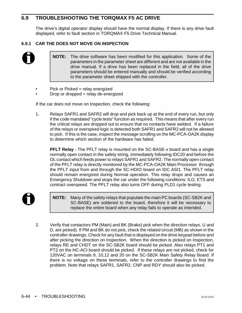
• TROUBLESHOOTING 42-02-2P226-44
NOTE: The drive software has been modified for this application. Some of theparameters in the parameter sheet are different and are not available in thedrive manual. If a drive has been replaced in the field, all of the driveparameters should be entered manually and should be verified accordingto the parameter sheet shipped with the controller.
NOTE: Many of the safety relays that populate the main PC boards (SC-SB2K andSC-BASE) are soldered to the board, therefore it will be necessary toreplace the entire board when any relay fails to operate as intended.
6.9 TROUBLESHOOTING THE TORQMAX F5 AC DRIVE
The drive’s digital operator display should have the normal display. If there is any drive faultdisplayed, refer to fault section in TORQMAX F5 Drive Technical Manual.
6.9.1 CAR THE DOES NOT MOVE ON INSPECTION
• Pick or Picked = relay energized• Drop or dropped = relay de-energized
If the car does not move on Inspection, check the following:
1. Relays SAFR1 and SAFR2 will drop and pick back up at the end of every run, but onlyif the code mandated “cycle tests” function as required. This means that after every runthe critical relays are dropped out to ensure that no contacts have welded. If a failureof the relays or overspeed logic is detected both SAFR1 and SAFR2 will not be allowedto pick. If this is the case, inspect the message scrolling on the MC-PCA-OA2K displayto determine which section of the hardware has failed.
PFLT Relay - The PFLT relay is mounted on the SC-BASE-x board and has a singlenormally open contact in the safety string, immediately following IDC20 and before theOL contact which feeds power to relays SAFR1 and SAFR2. The normally open contactof the PFLT relay is directly monitored by the MC-PCA-OA2K Main Processor throughthe PFLT input from and through the SC-HDIO board on IDC ASI1. The PFLT relayshould remain energized during Normal operation. This relay drops and causes anEmergency Shutdown and stops the car under the following conditions: ILO, ETS andcontract overspeed. The PFLT relay also turns OFF during PLD1 cycle testing.
2. Verify that contactors PM (Main) and BK (Brake) pick when the direction relays, U andD, are picked). If PM and BK do not pick, check the related circuit (MB) as shown in thecontroller drawings. Check for any fault that is displayed on the drive keypad before andafter picking the direction on Inspection. When the direction is picked on Inspection,relays RE and CHDT on the SC-SB2K board should be picked. Also relays PT1 andPT2 on the HC-ACI board should be picked. If these relays are not picked, check for120VAC on terminals 9, 10,12 and 20 on the SC-SB2K Main Safety Relay Board. Ifthere is no voltage on these terminals, refer to the controller drawings to find theproblem. Note that relays SAFR1, SAFR2, CNP and RDY should also be picked.
42-02-2P22 TROUBLESHOOTING • 6-45
3 To verify that the drive receives the direction, enable and inspection speed commandsignals from the (HC-ACI) board, do the following:
• To verify the drive enable signal, select parameter LF.99 and pick direction on
Inspection. The drive display should change from noP to Facc or rAcc. If itdoes not display Facc or rAcc, follow the controller drawings and verify theconnection to terminal X2A.16 (Enable terminal).
• To verify the commanded speed signal, select either parameter LF.88 or LF.86and pick direction on Inspection. If LF 88 is selected, the drive key pad shoulddisplay the inspection speed (Motor RPM) value.
• To verify the direction input signal, display parameter LF.99 and pick UPdirection on Inspection. The drive keypad display should change from noP (nooperation) to Facc (forward acceleration) and then to Fcon (forward constantrunning).
Pick DOWN direction on Inspection. The drive keypad display should changefrom nP (no operation) to rAcc (reverse acceleration) and then to rCon (reverseconstant running).
When direction is picked on Inspection, the DRO relay should pick. If this is not true,check the following:
a. Verify that the CNP and RDY relays are picked when the direction is not picked.If the RDY relay is not picked then check for a fault displayed on the drivekeypad. If there is no fault in the AC drive unit then check the wiring for the RDYcircuit. Relays PT1, PT2, UA or DA on the HC-ACI board should pick when thedirection relays are picked. If the main contactor is picking when the directionis picked, the SAFD relay on the HC-ACI board must pick. All the commandsignals to the VFAC drive are qualified by the normally open contact of theSAFD relay. If these relays are not picking, check for 36VAC between terminalsXC1, XC2 and +15 and -15 on the HC-ACI board. If there is no voltage, checkthe fuse on the primary side of the 30 VA transformer shown in drawing -3 ofthe job prints. Also check the wiring from the secondary of the same transformerto terminal XC1, XC2 on the HC-ACI board.
b. To verify the UP, DN , Enable and speed inputs to the drive, measure the DCvoltage between terminals X2.10 and the respective drive terminals. In the downdirection the voltage between X2.10 and X2.4 should be zero. In the up directionthe voltage between X2.10 and X.2.4 should be zero. The floating voltagebetween these points is approximately 24 VDC when the direction relays are notpicked.
If all the functions described in the above steps are working properly and the carstill does not move, then verify the drive parameters and compare them with thedrive parameter sheet which was shipped with the controller. The motor nameplate values should match the entered motor parameters. Some of the followingparameters, if not set properly, can prevent the car from moving on Inspection.
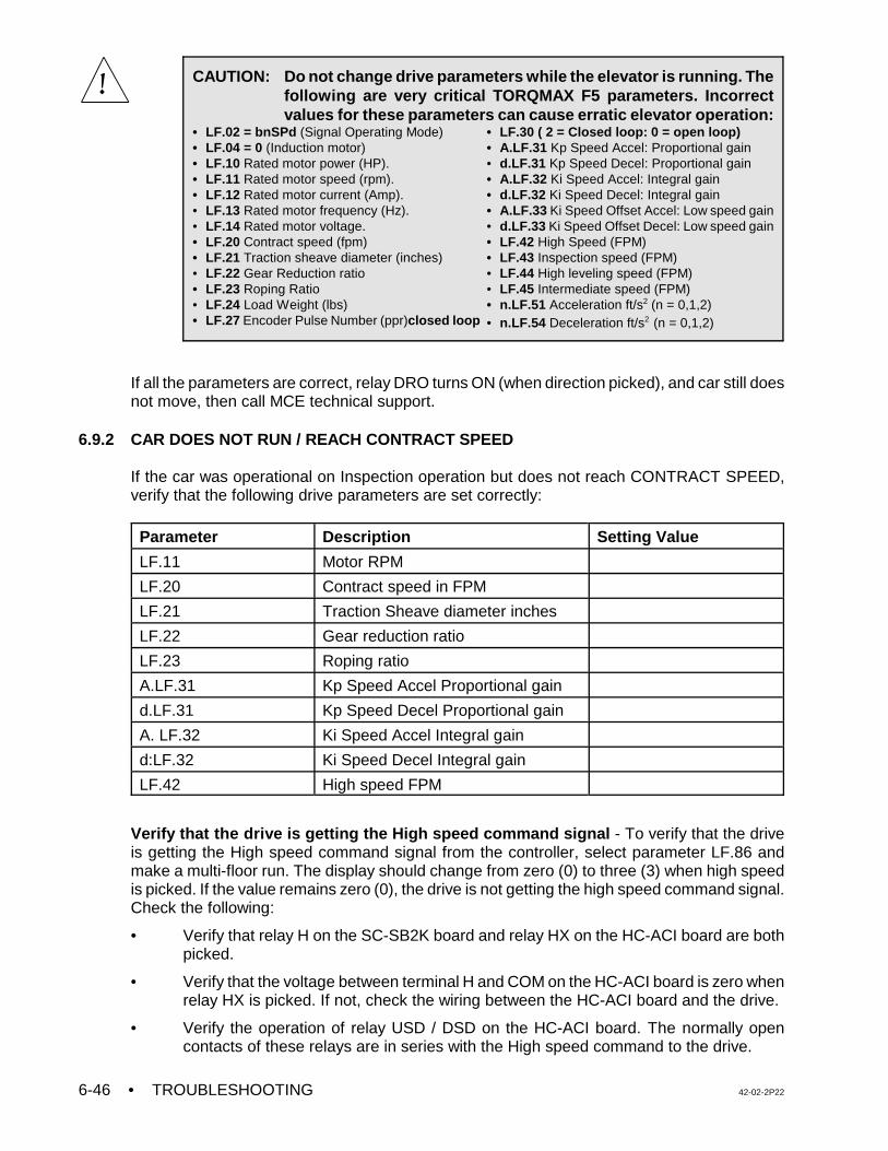
• TROUBLESHOOTING 42-02-2P226-46
CAUTION: Do not change drive parameters while the elevator is running. Thefollowing are very critical TORQMAX F5 parameters. Incorrectvalues for these parameters can cause erratic elevator operation:
• LF.02 = bnSPd (Signal Operating Mode)• LF.04 = 0 (Induction motor)• LF.10 Rated motor power (HP).• LF.11 Rated motor speed (rpm). • LF.12 Rated motor current (Amp).• LF.13 Rated motor frequency (Hz).• LF.14 Rated motor voltage.• LF.20 Contract speed (fpm)• LF.21 Traction sheave diameter (inches)• LF.22 Gear Reduction ratio • LF.23 Roping Ratio• LF.24 Load Weight (lbs)• LF.27 Encoder Pulse Number (ppr)closed loop
• LF.30 ( 2 = Closed loop: 0 = open loop)• A.LF.31 Kp Speed Accel: Proportional gain• d.LF.31 Kp Speed Decel: Proportional gain• A.LF.32 Ki Speed Accel: Integral gain• d.LF.32 Ki Speed Decel: Integral gain• A.LF.33 Ki Speed Offset Accel: Low speed gain• d.LF.33 Ki Speed Offset Decel: Low speed gain• LF.42 High Speed (FPM)• LF.43 Inspection speed (FPM)• LF.44 High leveling speed (FPM)• LF.45 Intermediate speed (FPM)• n.LF.51 Acceleration ft/s2 (n = 0,1,2)• n.LF.54 Deceleration ft/s2 (n = 0,1,2)
If all the parameters are correct, relay DRO turns ON (when direction picked), and car still doesnot move, then call MCE technical support.
6.9.2 CAR DOES NOT RUN / REACH CONTRACT SPEED
If the car was operational on Inspection operation but does not reach CONTRACT SPEED,verify that the following drive parameters are set correctly:
Parameter Description Setting Value
LF.11 Motor RPM
LF.20 Contract speed in FPM
LF.21 Traction Sheave diameter inches
LF.22 Gear reduction ratio
LF.23 Roping ratio
A.LF.31 Kp Speed Accel Proportional gain
d.LF.31 Kp Speed Decel Proportional gain
A. LF.32 Ki Speed Accel Integral gain
d:LF.32 Ki Speed Decel Integral gain
LF.42 High speed FPM
Verify that the drive is getting the High speed command signal - To verify that the driveis getting the High speed command signal from the controller, select parameter LF.86 andmake a multi-floor run. The display should change from zero (0) to three (3) when high speedis picked. If the value remains zero (0), the drive is not getting the high speed command signal.Check the following:
• Verify that relay H on the SC-SB2K board and relay HX on the HC-ACI board are bothpicked.
• Verify that the voltage between terminal H and COM on the HC-ACI board is zero whenrelay HX is picked. If not, check the wiring between the HC-ACI board and the drive.
• Verify the operation of relay USD / DSD on the HC-ACI board. The normally opencontacts of these relays are in series with the High speed command to the drive.
42-02-2P22 TROUBLESHOOTING • 6-47
NOTE: It is mandatory to have 40% counterweight.
If the car does not reach Contract speed - If the drive is getting the High speed commandsignal but the car does not reach Contract speed, perform one of the following checks:
New motor - If the hoist motor is new, verify the following:
• LF.20 and LF.42 are set to the correct value in FPM.
• Rated motor speed (LF.11) is set to motor full load RPM.
• LF.22 (Gear reduction ration) is set correctly.
Old motor - If the hoist motor is old, and the car does not reach contract speed (empty cardown), display LF.90 and do the following:
1. Decrease the field weakening speed LF.16 to approximately 2/3 of the motorsynchronous speed.
2. Set the power factor parameter LF.15 = 0.9.
3. Decrease the rated motor speed parameter LF.11 in steps of 20 until the rated speedis reached (empty car down).
4. If the current drawn by the motor is too high (parameter ru.90) then increase parameterLF.11 in steps of 10.
6.9.3 CAR OVERSHOOTS OR THE DRIVE TRIPS on 'E. OL' or 'E. OP' ON ACCELERATION
If, during acceleration, the car OVERSHOOTS or trips on OVER VOLTAGE, then check thefollowing:
1. Decrease drive parameters LF.51 Acceleration Rate and LF.52 Acceleration Jerk .
2. Increase the drive gains by increase parameters LF. 31 and LF.32.
3. Turn OFF the power and wait for 5 minutes so the DC bus voltage is not present in thedynamic braking circuit. Using a voltmeter, verify that no voltage is present. Then verifythe value of the dynamic braking resistor with the job prints and check for any looseconnection.
6.9.4 DRIVE TRIPS 'E.OP' OR THE CAR OVERSHOOTS ON DECELERATION
If the drive trips on 'E.OP' during deceleration or overshoots the floors, then check thefollowing:
1. Verify that all the items described in Section 6.9.3 and the counter weight are setproperly.
2. Verify that the High Level speed, Level speed and Intermediate speed (if required) areset as described in Sections 4.8.1 and 4.9.4 'c'..
3. Increase the deceleration parameter LF.54 and verify that the High Level and Levelspeeds are adjusted to provide a smooth transition from high speed to leveling speed.
4. If the value of parameter LF.55 Approach Jerk is too high it can cause the car toovershoot and relevel.
5. If all the items above are set properly and the car still overshoots, consult the Drivemanual. If the problem still exists then increase the slow down distance on a couple of
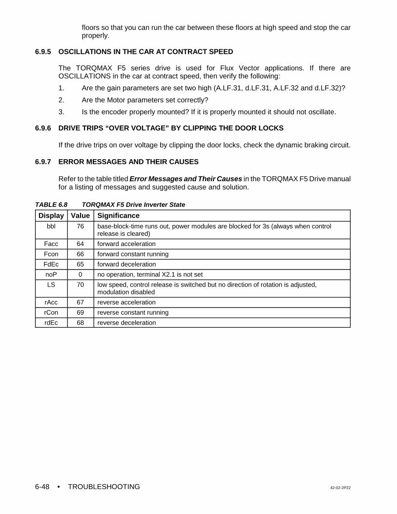
• TROUBLESHOOTING 42-02-2P226-48
floors so that you can run the car between these floors at high speed and stop the carproperly.
6.9.5 OSCILLATIONS IN THE CAR AT CONTRACT SPEED
The TORQMAX F5 series drive is used for Flux Vector applications. If there areOSCILLATIONS in the car at contract speed, then verify the following:
1. Are the gain parameters are set two high (A.LF.31, d.LF.31, A.LF.32 and d.LF.32)?
2. Are the Motor parameters set correctly?
3. Is the encoder properly mounted? If it is properly mounted it should not oscillate.
6.9.6 DRIVE TRIPS “OVER VOLTAGE” BY CLIPPING THE DOOR LOCKS
If the drive trips on over voltage by clipping the door locks, check the dynamic braking circuit.
6.9.7 ERROR MESSAGES AND THEIR CAUSES
Refer to the table titled Error Messages and Their Causes in the TORQMAX F5 Drive manualfor a listing of messages and suggested cause and solution.
TABLE 6.8 TORQMAX F5 Drive Inverter State
Display Value Significancebbl 76 base-block-time runs out, power modules are blocked for 3s (always when control
release is cleared)
Facc 64 forward acceleration
Fcon 66 forward constant running
FdEc 65 forward deceleration
noP 0 no operation, terminal X2.1 is not set
LS 70 low speed, control release is switched but no direction of rotation is adjusted,modulation disabled
rAcc 67 reverse acceleration
rCon 69 reverse constant running
rdEc 68 reverse deceleration
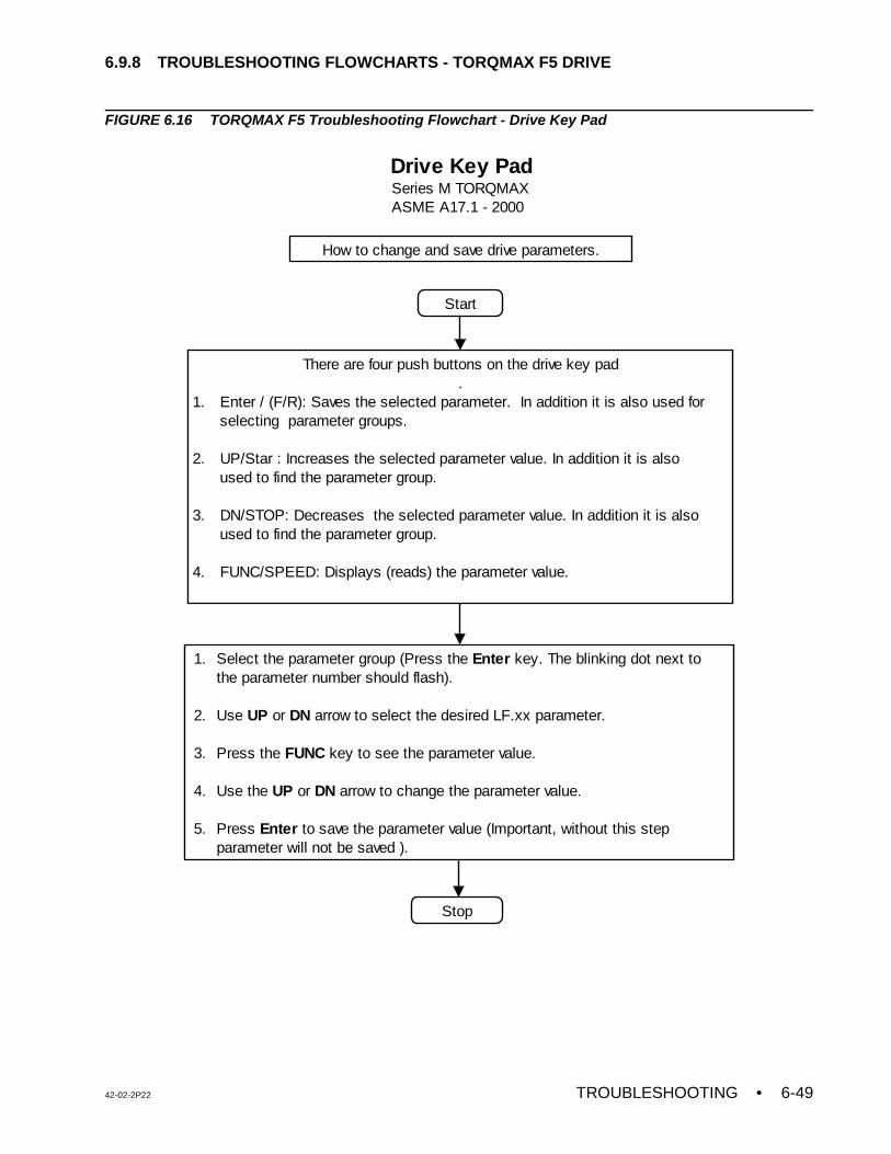
42-02-2P22 TROUBLESHOOTING • 6-49
Start
There are four push buttons on the drive key pad.
1. Enter / (F/R): Saves the selected parameter. In addition it is also used for selecting parameter groups.
2. UP/Star : Increases the selected parameter value. In addition it is also used to find the parameter group.
3. DN/STOP: Decreases the selected parameter value. In addition it is also used to find the parameter group.
4. FUNC/SPEED: Displays (reads) the parameter value.
1. Select the parameter group (Press the Enter key. The blinking dot next to the parameter number should flash). 2. Use UP or DN arrow to select the desired LF.xx parameter.
3. Press the FUNC key to see the parameter value.
4. Use the UP or DN arrow to change the parameter value. 5. Press Enter to save the parameter value (Important, without this step parameter will not be saved ).
Stop
Drive Key PadSeries M TORQMAXASME A17.1 - 2000
How to change and save drive parameters.
6.9.8 TROUBLESHOOTING FLOWCHARTS - TORQMAX F5 DRIVE
FIGURE 6.16 TORQMAX F5 Troubleshooting Flowchart - Drive Key Pad
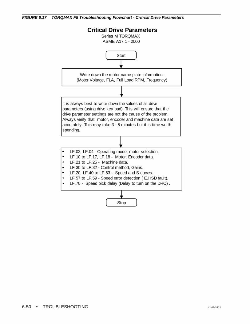
• TROUBLESHOOTING 42-02-2P226-50
Start
Write down the motor name plate information.(Motor Voltage, FLA, Full Load RPM, Frequency)
It is always best to write down the values of all drive parameters (using drive key pad). This will ensure that the drive parameter settings are not the cause of the problem. Always verify that motor, encoder and machine data are set accurately. This may take 3 - 5 minutes but it is time worth spending.
LF.02, LF.04 - Operating mode, motor selection.LF.10 to LF.17, LF.18 - Motor, Encoder data.LF.21 to LF.25 - Machine data.LF.30 to LF.32 - Control method, Gains.LF.20, LF.40 to LF.53 - Speed and S curves.LF.57 to LF.59 - Speed error detection ( E.HSD fault). LF.70 - Speed pick delay (Delay to turn on the DRO) .
Stop
Critical Drive Parameters Series M TORQMAX ASME A17.1 - 2000
FIGURE 6.17 TORQMAX F5 Troubleshooting Flowchart - Critical Drive Parameters
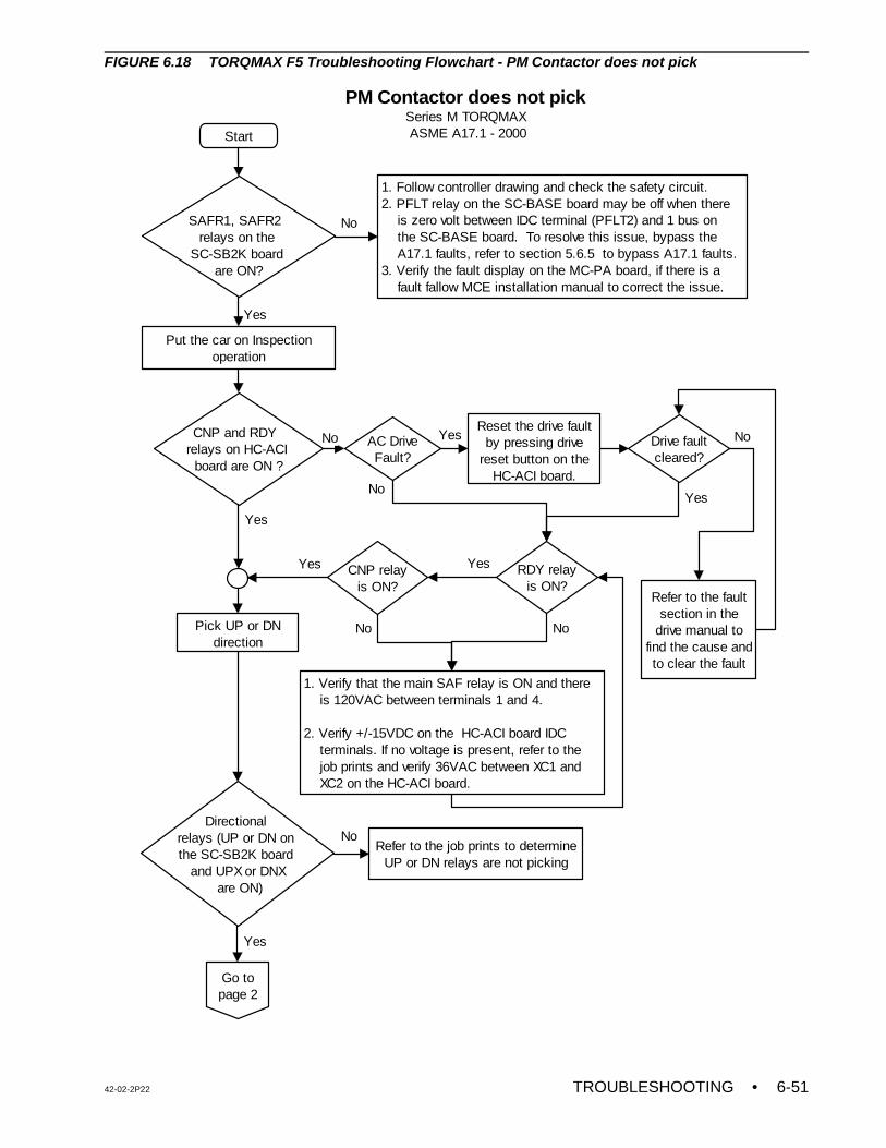
42-02-2P22 TROUBLESHOOTING • 6-51
Start
Put the car on Inspection operation
CNP and RDY relays on HC-ACI
board are ON ?
Reset the drive fault by pressing drive
reset button on the HC-ACI board.
CNP relayis ON?
Pick UP or DN direction
Directional relays (UP or DN on the SC-SB2K board
and UPX or DNX are ON)
Refer to the fault section in the
drive manual to find the cause and to clear the fault
Yes
Refer to the job prints to determine UP or DN relays are not picking
No
PM Contactor does not pick Series M TORQMAX ASME A17.1 - 2000
SAFR1, SAFR2 relays on the
SC-SB2K board are ON?
1. Follow controller drawing and check the safety circuit.2. PFLT relay on the SC-BASE board may be off when there is zero volt between IDC terminal (PFLT2) and 1 bus on the SC-BASE board. To resolve this issue, bypass the A17.1 faults, refer to section 5.6.5 to bypass A17.1 faults.3. Verify the fault display on the MC-PA board, if there is a fault fallow MCE installation manual to correct the issue.
No
Yes
AC DriveFault?
No Yes
RDY relayis ON?
1. Verify that the main SAF relay is ON and there is 120VAC between terminals 1 and 4.
2. Verify +/-15VDC on the HC-ACI board IDC terminals. If no voltage is present, refer to the job prints and verify 36VAC between XC1 and XC2 on the HC-ACI board.
Drive faultcleared?
No
No
Go to page 2
Yes
Yes
YesYes
No No
FIGURE 6.18 TORQMAX F5 Troubleshooting Flowchart - PM Contactor does not pick
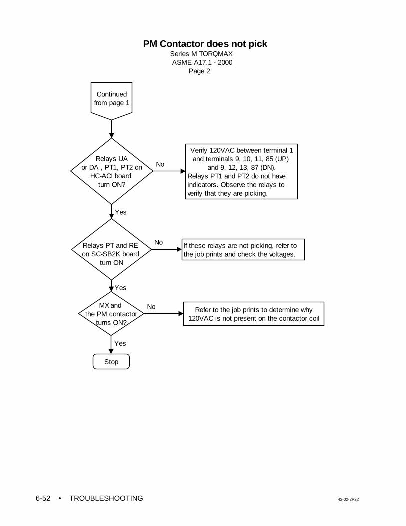
• TROUBLESHOOTING 42-02-2P226-52
Relays PT and RE on SC-SB2K board
turn ON
MX and the PM contactor
turns ON?
Verify 120VAC between terminal 1 and terminals 9, 10, 11, 85 (UP)
and 9, 12, 13, 87 (DN).Relays PT1 and PT2 do not have indicators. Observe the relays to verify that they are picking.
Relays UAor DA , PT1, PT2 on
HC-ACI board turn ON?
Refer to the job prints to determine why 120VAC is not present on the contactor coil
No
Yes
Yes
Stop
No
Yes
If these relays are not picking, refer to the job prints and check the voltages.
No
Continued from page 1
PM Contactor does not pick Series M TORQMAX ASME A17.1 - 2000 Page 2
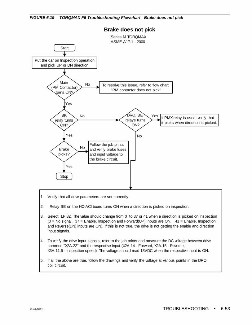
42-02-2P22 TROUBLESHOOTING • 6-53
Start
Put the car on Inspection operation and pick UP or DN direction
Main (PM Contactor)
turns ON?
To resolve this issue, refer to flow chart "PM contactor does not pick"
BKrelay turns
ON?
No
Yes
DRO, BE relays turns
ON?
No If PMX relay is used, verify that it picks when direction is picked.
1. Verify that all drive parameters are set correctly.
2. Relay BE on the HC-ACI board turns ON when a direction is picked on inspection. 3. Select LF.82. The value should change from 0 to 37 or 41 when a direction is picked on Inspection (0 = No signal, 37 = Enable, Inspection and Forward(UP) inputs are ON, 41 = Enable, Inspection and Reverse(DN) inputs are ON). If this is not true, the drive is not getting the enable and direction input signals. 4. To verify the drive input signals, refer to the job prints and measure the DC voltage between drive common "X2A.22" and the respective input (X2A.14 - Forward, X2A.15 - Reverse, X3A.11.5 - Inspection speed). The voltage should read 18VDC when the respective input is ON. 5. If all the above are true, follow the drawings and verify the voltage at various points in the DRO coil circuit.
No
Yes
Stop
Brake does not pickSeries M TORQMAXASME A17.1 - 2000
Brakepicks?
Yes
Follow the job prints and verify brake fuses and input voltage to the brake circuit.
Yes
No
FIGURE 6.19 TORQMAX F5 Troubleshooting Flowchart - Brake does not pick
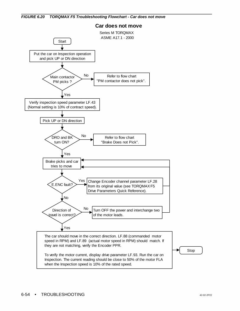
• TROUBLESHOOTING 42-02-2P226-54
Start
Put the car on Inspection operation and pick UP or DN direction
Main contactorPM picks ?
Refer to flow chart "PM contactor does not pick".
No
Verify inspection speed parameter LF.43 (Normal setting is 10% of contract speed).
Yes
DRO and BKturn ON?
Refer to flow chart"Brake Does not Pick".
No
Brake picks and car tries to move
E.ENC fault?
Yes
Change Encoder channel parameter LF.28 from its original value (see TORQMAX F5 Drive Parameters Quick Reference).
Direction of travel is correct?
No
Yes
Turn OFF the power and interchange two of the motor leads.
No
The car should move in the correct direction. LF.88 (commanded motor speed in RPM) and LF.89 (actual motor speed in RPM) should match. If they are not matching, verify the Encoder PPR.
To verify the motor current, display drive parameter LF.93. Run the car on Inspection. The current reading should be close to 50% of the motor FLA when the Inspection speed is 10% of the rated speed.
Yes
Stop
Car does not move Series M TORQMAX ASME A17.1 - 2000
Pick UP or DN direction
FIGURE 6.20 TORQMAX F5 Troubleshooting Flowchart - Car does not move
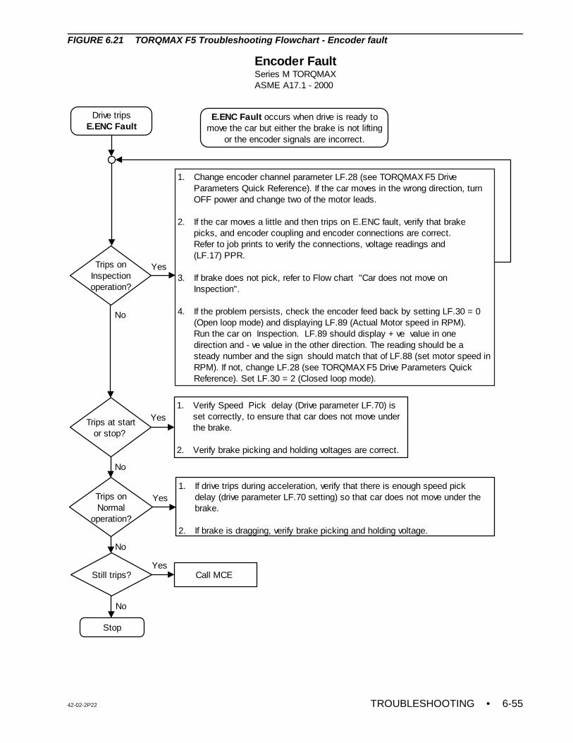
42-02-2P22 TROUBLESHOOTING • 6-55
Drive tripsE.ENC Fault
Trips onInspection operation?
Trips onNormal
operation?
Trips at startor stop?
Still trips?
1. If drive trips during acceleration, verify that there is enough speed pick delay (drive parameter LF.70 setting) so that car does not move under the brake.
2. If brake is dragging, verify brake picking and holding voltage.
1. Verify Speed Pick delay (Drive parameter LF.70) is set correctly, to ensure that car does not move under the brake.
2. Verify brake picking and holding voltages are correct.
Call MCE
Stop
Yes
Yes
No
Yes
1. Change encoder channel parameter LF.28 (see TORQMAX F5 Drive Parameters Quick Reference). If the car moves in the wrong direction, turn OFF power and change two of the motor leads.
2. If the car moves a little and then trips on E.ENC fault, verify that brake picks, and encoder coupling and encoder connections are correct. Refer to job prints to verify the connections, voltage readings and (LF.17) PPR.
3. If brake does not pick, refer to Flow chart "Car does not move on Inspection". 4. If the problem persists, check the encoder feed back by setting LF.30 = 0 (Open loop mode) and displaying LF.89 (Actual Motor speed in RPM). Run the car on Inspection. LF.89 should display + ve value in one direction and - ve value in the other direction. The reading should be a steady number and the sign should match that of LF.88 (set motor speed in RPM). If not, change LF.28 (see TORQMAX F5 Drive Parameters Quick Reference). Set LF.30 = 2 (Closed loop mode).
Yes
Encoder FaultSeries M TORQMAXASME A17.1 - 2000
E.ENC Fault occurs when drive is ready to move the car but either the brake is not lifting
or the encoder signals are incorrect.
No
No
No
FIGURE 6.21 TORQMAX F5 Troubleshooting Flowchart - Encoder fault
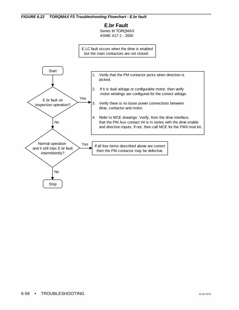
• TROUBLESHOOTING 42-02-2P226-56
Start
E.br fault oninspection operation?
1. Verify that the PM contactor picks when direction is picked.
2. If it is dual voltage or configurable motor, then verify motor windings are configured for the correct voltage. 3. Verify there is no loose power connections between drive, contactor and motor.
4. Refer to MCE drawings. Verify, from the drive interface, that the PM Aux contact #4 is in series with the drive enable and direction inputs. If not, then call MCE for the PMX mod kit.
Normal operation and it still trips E.br fault
intermittently?
Stop
No
If all four items described above are correct then the PM contactor may be defective.
Yes
No
Yes
E.br FaultSeries M TORQMAXASME A17.1 - 2000
E.LC fault occurs when the drive is enabled but the main contactors are not closed.
FIGURE 6.22 TORQMAX F5 Troubleshooting Flowchart - E.br fault
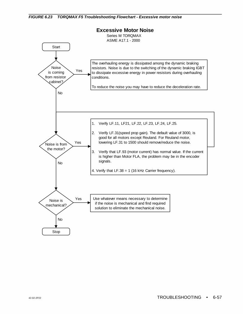
42-02-2P22 TROUBLESHOOTING • 6-57
Start
Noise ismechanical?
Use whatever means necessary to determine if the noise is mechanical and find required solution to eliminate the mechanical noise.
Noiseis coming
from resistor cabinet?
The overhauling energy is dissipated among the dynamic braking resistors. Noise is due to the switching of the dynamic braking IGBT to dissipate excessive energy in power resistors during overhauling conditions.
To reduce the noise you may have to reduce the deceleration rate.
Noise is fromthe motor?
Yes
No
Yes
1. Verify LF.11, LF21, LF.22, LF.23, LF.24, LF.25.
2. Verify LF.31(speed prop gain). The default value of 3000, is good for all motors except Reuland. For Reuland motor, lowering LF.31 to 1500 should remove/reduce the noise.
3. Verify that LF.93 (motor current) has normal value. If the current is higher than Motor FLA, the problem may be in the encoder signals.
4. Verify that LF.38 = 1 (16 kHz Carrier frequency).
Stop
Yes
No
No
Excessive Motor Noise Series M TORQMAX ASME A17.1 - 2000
FIGURE 6.23 TORQMAX F5 Troubleshooting Flowchart - Excessive motor noise
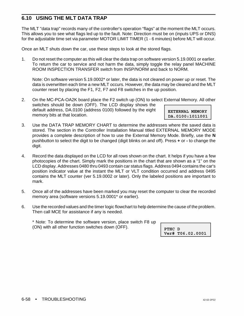
• TROUBLESHOOTING 42-02-2P226-58
EXTERNAL MEMORY DA.0100:1011001
PTHC D Ver# T06.02.0001
6.10 USING THE MLT DATA TRAP
The MLT "data trap" records many of the controller's operation “flags” at the moment the MLT occurs.This allows you to see what flags led up to the fault. Note: Direction must be on (inputs UPS or DNS)for the adjustable time set via parameter MOTOR LIMIT TIMER (1 - 6 minutes) before MLT will occur.
Once an MLT shuts down the car, use these steps to look at the stored flags.
1. Do not reset the computer as this will clear the data trap on software version 5.19.0001 or earlier.To return the car to service and not harm the data, simply toggle the relay panel MACHINEROOM INSPECTION TRANSFER switch from INSP/NORM and back to NORM.
Note: On software version 5.19.0002* or later, the data is not cleared on power up or reset. Thedata is overwritten each time a new MLT occurs. However, the data may be cleared and the MLTcounter reset by placing the F1, F2, F7 and F8 switches in the up position.
2. On the MC-PCA-OA2K board place the F2 switch up (ON) to select External Memory. All otherswitches should be down (OFF). The LCD display shows thedefault address, DA.0100 (address 0100) followed by the eightmemory bits at that location.
3. Use the DATA TRAP MEMORY CHART to determine the addresses where the saved data isstored. The section in the Controller Installation Manual titled EXTERNAL MEMORY MODEprovides a complete description of how to use the External Memory Mode. Briefly, use the Npushbutton to select the digit to be changed (digit blinks on and off). Press + or - to change thedigit.
4. Record the data displayed on the LCD for all rows shown on the chart. It helps if you have a fewphotocopies of the chart. Simply mark the positions in the chart that are shown as a “1" on theLCD display. Addresses 0480 thru 0493 contain car status flags. Address 0494 contains the car'sposition indicator value at the instant the MLT or VLT condition occurred and address 0495contains the MLT counter (ver 5.19.0002 or later). Only the labeled positions are important tomark.
5. Once all of the addresses have been marked you may reset the computer to clear the recordedmemory area (software versions 5.19.0001* or earlier).
6. Use the recorded values and the timer logic flowchart to help determine the cause of the problem.Then call MCE for assistance if any is needed.
* Note: To determine the software version, place switch F8 up(ON) with all other function switches down (OFF).
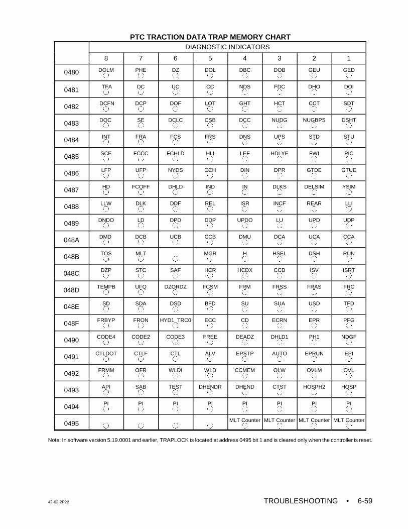
42-02-2P22 TROUBLESHOOTING • 6-59
PTC TRACTION DATA TRAP MEMORY CHARTDIAGNOSTIC INDICATORS
8 7 6 5 4 3 2 1
0480 DOLM±
PHE±
DZ±
DOL±
DBC±
DOB±
GEU±
GED±
0481 TFA±
DC±
UC±
CC±
NDS±
FDC±
DHO±
DOI±
0482 DCFN±
DCP±
DOF±
LOT±
GHT±
HCT±
CCT±
SDT±
0483 DOC ±
SE±
DCLC±
CSB±
DCC±
NUDG±
NUGBPS±
DSHT±
0484 INT±
FRA±
FCS±
FRS±
DNS±
UPS±
STD±
STU±
0485 SCE±
FCCC±
FCHLD±
HLI±
LEF±
HDLYE±
FWI±
PIC±
0486 LFP±
UFP±
NYDS±
CCH±
DIN±
DPR±
GTDE±
GTUE±
0487 HD±
FCOFF±
DHLD±
IND±
IN±
DLKS±
DELSIM±
YSIM±
0488 LLW±
DLK±
DDF±
REL±
ISR±
INCF±
REAR±
LLI±
0489 DNDO±
LD±
DPD±
DDP±
UPDO±
LU±
UPD±
UDP±
048A DMD ±
DCB±
UCB±
CCB±
DMU±
DCA±
UCA±
CCA±
048B TOS±
MLT± ±
MGR±
H±
HSEL±
DSH±
RUN±
048C DZP±
STC±
SAF±
HCR±
HCDX±
CCD±
ISV±
ISRT±
048D TEMPB±
UFQ±
DZORDZ±
FCSM±
FRM±
FRSS±
FRAS±
FRC±
048E SD±
SDA±
DSD±
BFD±
SU±
SUA±
USD±
TFD±
048F FRBYP±
FRON±
HYD1_TRC0±
ECC±
CD±
ECRN±
EPR±
PFG±
0490 CODE4±
CODE2±
CODE3±
FREE±
DEADZ±
DHLD1±
PH1±
NDGF±
0491 CTLDOT±
CTLF±
CTL±
ALV±
EPSTP±
AUTO±
EPRUN±
EPI±
0492 FRMM±
OFR±
WLDI±
WLD±
CCMEM±
OLW±
OVLM±
OVL±
0493 API±
SAB±
TEST±
DHENDR±
DHEND±
CTST±
HOSPH2±
HOSP±
0494 PI±
PI±
PI±
PI±
PI±
PI±
PI±
PI±
0495 ± ± ± ±MLT Counter
±MLT Counter
±MLT Counter
±MLT Counter
±
Note: In software version 5.19.0001 and earlier, TRAPLOCK is located at address 0495 bit 1 and is cleared only when the controller is reset.
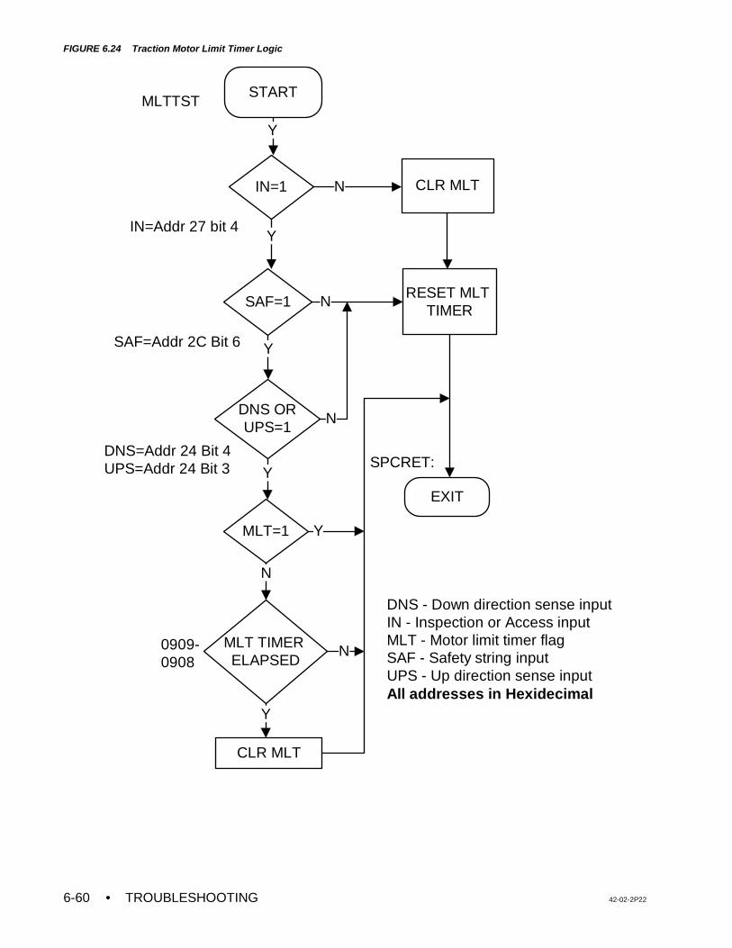
• TROUBLESHOOTING 42-02-2P226-60
CLR MLT
START
EXIT
IN=1
SAF=1
DNS ORUPS=1
MLT=1
MLT TIMER ELAPSED
RESET MLT TIMER
DNS - Down direction sense inputIN - Inspection or Access inputMLT - Motor limit timer flagSAF - Safety string inputUPS - Up direction sense inputAll addresses in Hexidecimal
SPCRET:
MLTTST
IN=Addr 27 bit 4
SAF=Addr 2C Bit 6
DNS=Addr 24 Bit 4UPS=Addr 24 Bit 3
0909-0908
CLR MLT
N
Y
Y
N
Y
N
Y
Y
N
N
Y
FIGURE 6.24 Traction Motor Limit Timer Logic
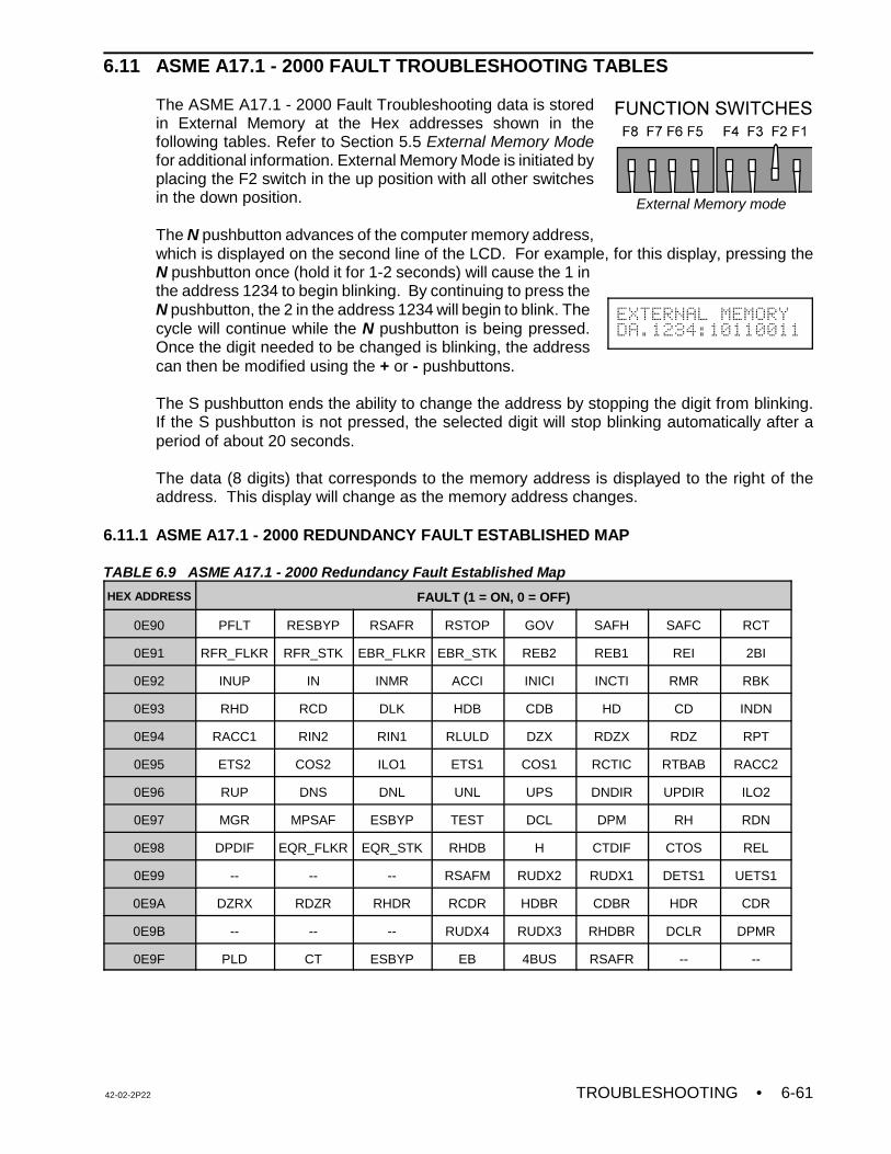
42-02-2P22 TROUBLESHOOTING • 6-61
External Memory mode
6.11 ASME A17.1 - 2000 FAULT TROUBLESHOOTING TABLES
The ASME A17.1 - 2000 Fault Troubleshooting data is storedin External Memory at the Hex addresses shown in thefollowing tables. Refer to Section 5.5 External Memory Modefor additional information. External Memory Mode is initiated byplacing the F2 switch in the up position with all other switchesin the down position.
The N pushbutton advances of the computer memory address,which is displayed on the second line of the LCD. For example, for this display, pressing theN pushbutton once (hold it for 1-2 seconds) will cause the 1 inthe address 1234 to begin blinking. By continuing to press theN pushbutton, the 2 in the address 1234 will begin to blink. Thecycle will continue while the N pushbutton is being pressed.Once the digit needed to be changed is blinking, the addresscan then be modified using the + or - pushbuttons.
The S pushbutton ends the ability to change the address by stopping the digit from blinking.If the S pushbutton is not pressed, the selected digit will stop blinking automatically after aperiod of about 20 seconds.
The data (8 digits) that corresponds to the memory address is displayed to the right of theaddress. This display will change as the memory address changes.
6.11.1 ASME A17.1 - 2000 REDUNDANCY FAULT ESTABLISHED MAP
TABLE 6.9 ASME A17.1 - 2000 Redundancy Fault Established Map
HEX ADDRESS FAULT (1 = ON, 0 = OFF)
0E90 PFLT RESBYP RSAFR RSTOP GOV SAFH SAFC RCT
0E91 RFR_FLKR RFR_STK EBR_FLKR EBR_STK REB2 REB1 REI 2BI
0E92 INUP IN INMR ACCI INICI INCTI RMR RBK
0E93 RHD RCD DLK HDB CDB HD CD INDN
0E94 RACC1 RIN2 RIN1 RLULD DZX RDZX RDZ RPT
0E95 ETS2 COS2 ILO1 ETS1 COS1 RCTIC RTBAB RACC2
0E96 RUP DNS DNL UNL UPS DNDIR UPDIR ILO2
0E97 MGR MPSAF ESBYP TEST DCL DPM RH RDN
0E98 DPDIF EQR_FLKR EQR_STK RHDB H CTDIF CTOS REL
0E99 -- -- -- RSAFM RUDX2 RUDX1 DETS1 UETS1
0E9A DZRX RDZR RHDR RCDR HDBR CDBR HDR CDR
0E9B -- -- -- RUDX4 RUDX3 RHDBR DCLR DPMR
0E9F PLD CT ESBYP EB 4BUS RSAFR -- --
EXTERNAL MEMORY
DA.1234:10110011
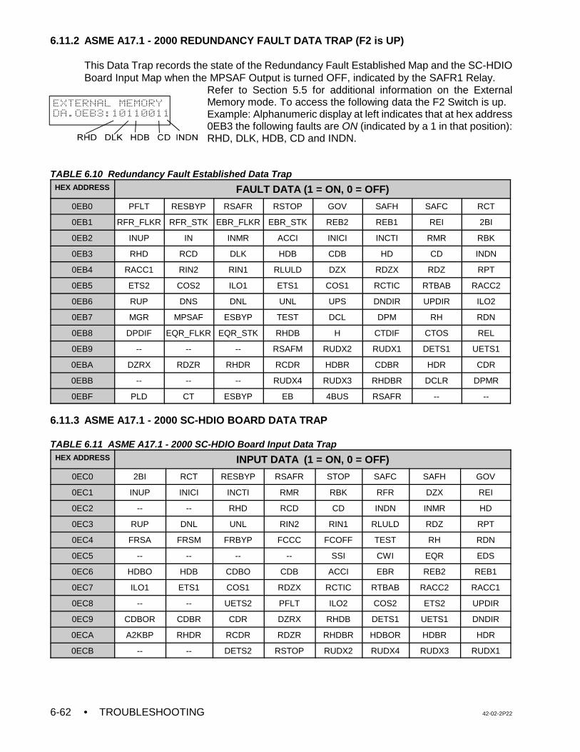
• TROUBLESHOOTING 42-02-2P226-62
6.11.2 ASME A17.1 - 2000 REDUNDANCY FAULT DATA TRAP (F2 is UP)
This Data Trap records the state of the Redundancy Fault Established Map and the SC-HDIOBoard Input Map when the MPSAF Output is turned OFF, indicated by the SAFR1 Relay.
Refer to Section 5.5 for additional information on the ExternalMemory mode. To access the following data the F2 Switch is up. Example: Alphanumeric display at left indicates that at hex address0EB3 the following faults are ON (indicated by a 1 in that position):RHD, DLK, HDB, CD and INDN.
TABLE 6.10 Redundancy Fault Established Data TrapHEX ADDRESS FAULT DATA (1 = ON, 0 = OFF)
0EB0 PFLT RESBYP RSAFR RSTOP GOV SAFH SAFC RCT
0EB1 RFR_FLKR RFR_STK EBR_FLKR EBR_STK REB2 REB1 REI 2BI
0EB2 INUP IN INMR ACCI INICI INCTI RMR RBK
0EB3 RHD RCD DLK HDB CDB HD CD INDN
0EB4 RACC1 RIN2 RIN1 RLULD DZX RDZX RDZ RPT
0EB5 ETS2 COS2 ILO1 ETS1 COS1 RCTIC RTBAB RACC2
0EB6 RUP DNS DNL UNL UPS DNDIR UPDIR ILO2
0EB7 MGR MPSAF ESBYP TEST DCL DPM RH RDN
0EB8 DPDIF EQR_FLKR EQR_STK RHDB H CTDIF CTOS REL
0EB9 -- -- -- RSAFM RUDX2 RUDX1 DETS1 UETS1
0EBA DZRX RDZR RHDR RCDR HDBR CDBR HDR CDR
0EBB -- -- -- RUDX4 RUDX3 RHDBR DCLR DPMR
0EBF PLD CT ESBYP EB 4BUS RSAFR -- --
6.11.3 ASME A17.1 - 2000 SC-HDIO BOARD DATA TRAP
TABLE 6.11 ASME A17.1 - 2000 SC-HDIO Board Input Data TrapHEX ADDRESS INPUT DATA (1 = ON, 0 = OFF)
0EC0 2BI RCT RESBYP RSAFR STOP SAFC SAFH GOV
0EC1 INUP INICI INCTI RMR RBK RFR DZX REI
0EC2 -- -- RHD RCD CD INDN INMR HD
0EC3 RUP DNL UNL RIN2 RIN1 RLULD RDZ RPT
0EC4 FRSA FRSM FRBYP FCCC FCOFF TEST RH RDN
0EC5 -- -- -- -- SSI CWI EQR EDS
0EC6 HDBO HDB CDBO CDB ACCI EBR REB2 REB1
0EC7 ILO1 ETS1 COS1 RDZX RCTIC RTBAB RACC2 RACC1
0EC8 -- -- UETS2 PFLT ILO2 COS2 ETS2 UPDIR
0EC9 CDBOR CDBR CDR DZRX RHDB DETS1 UETS1 DNDIR
0ECA A2KBP RHDR RCDR RDZR RHDBR HDBOR HDBR HDR
0ECB -- -- DETS2 RSTOP RUDX2 RUDX4 RUDX3 RUDX1
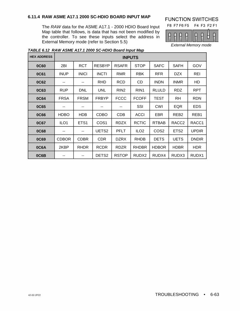
42-02-2P22 TROUBLESHOOTING • 6-63
External Memory mode
6.11.4 RAW ASME A17.1 2000 SC-HDIO BOARD INPUT MAP
The RAW data for the ASME A17.1 - 2000 HDIO Board InputMap table that follows, is data that has not been modified bythe controller. To see these inputs select the address inExternal Memory mode (refer to Section 5.5)
TABLE 6.12 RAW ASME A17.1 2000 SC-HDIO Board Input Map
HEX ADDRESS INPUTS
0C60 2BI RCT RESBYP RSAFR STOP SAFC SAFH GOV
0C61 INUP INICI INCTI RMR RBK RFR DZX REI
0C62 -- -- RHD RCD CD INDN INMR HD
0C63 RUP DNL UNL RIN2 RIN1 RLULD RDZ RPT
0C64 FRSA FRSM FRBYP FCCC FCOFF TEST RH RDN
0C65 -- -- -- -- SSI CWI EQR EDS
0C66 HDBO HDB CDBO CDB ACCI EBR REB2 REB1
0C67 ILO1 ETS1 COS1 RDZX RCTIC RTBAB RACC2 RACC1
0C68 -- -- UETS2 PFLT ILO2 COS2 ETS2 UPDIR
0C69 CDBOR CDBR CDR DZRX RHDB DETS UETS DNDIR
0C6A 2KBP RHDR RCDR RDZR RHDBR HDBOR HDBR HDR
0C6B -- -- DETS2 RSTOP RUDX2 RUDX4 RUDX3 RUDX1
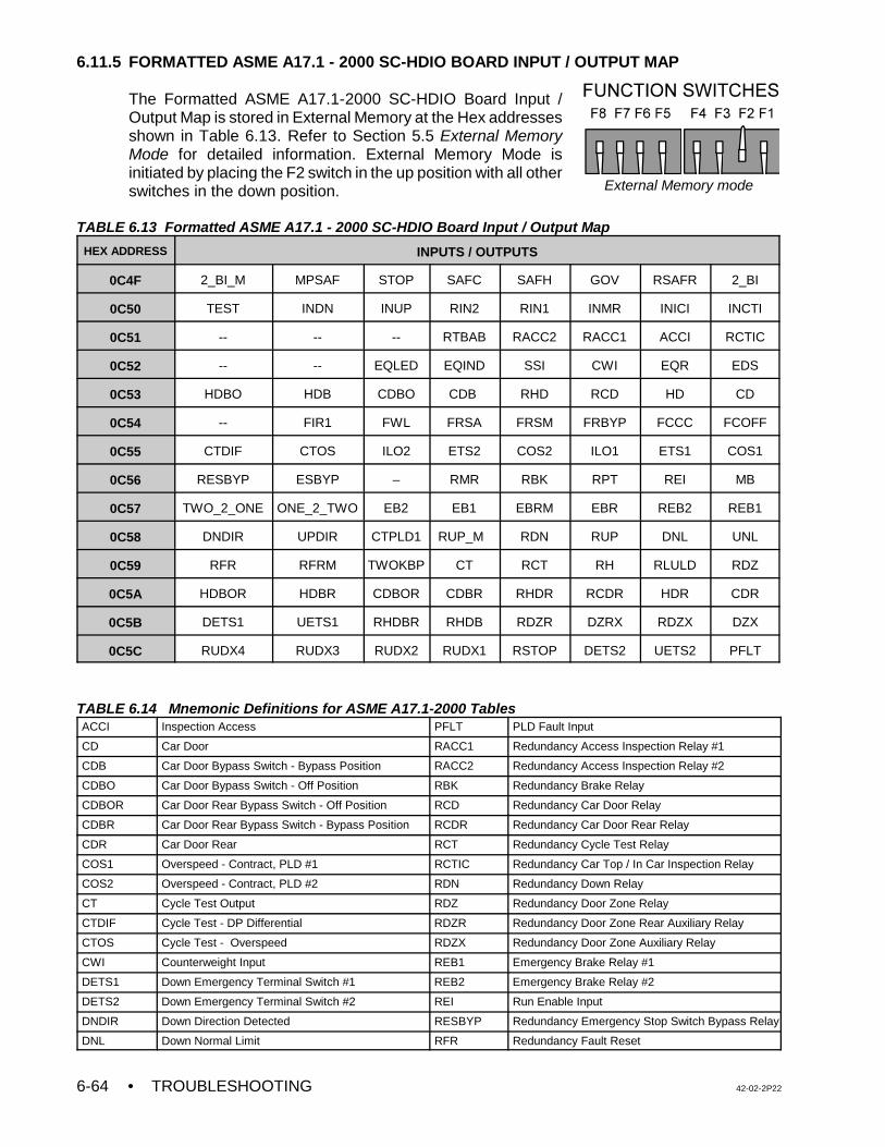
• TROUBLESHOOTING 42-02-2P226-64
External Memory mode
6.11.5 FORMATTED ASME A17.1 - 2000 SC-HDIO BOARD INPUT / OUTPUT MAP
The Formatted ASME A17.1-2000 SC-HDIO Board Input /Output Map is stored in External Memory at the Hex addressesshown in Table 6.13. Refer to Section 5.5 External MemoryMode for detailed information. External Memory Mode isinitiated by placing the F2 switch in the up position with all otherswitches in the down position.
TABLE 6.13 Formatted ASME A17.1 - 2000 SC-HDIO Board Input / Output Map
HEX ADDRESS INPUTS / OUTPUTS
0C4F 2_BI_M MPSAF STOP SAFC SAFH GOV RSAFR 2_BI
0C50 TEST INDN INUP RIN2 RIN1 INMR INICI INCTI
0C51 -- -- -- RTBAB RACC2 RACC1 ACCI RCTIC
0C52 -- -- EQLED EQIND SSI CWI EQR EDS
0C53 HDBO HDB CDBO CDB RHD RCD HD CD
0C54 -- FIR1 FWL FRSA FRSM FRBYP FCCC FCOFF
0C55 CTDIF CTOS ILO2 ETS2 COS2 ILO1 ETS1 COS1
0C56 RESBYP ESBYP – RMR RBK RPT REI MB
0C57 TWO_2_ONE ONE_2_TWO EB2 EB1 EBRM EBR REB2 REB1
0C58 DNDIR UPDIR CTPLD1 RUP_M RDN RUP DNL UNL
0C59 RFR RFRM TWOKBP CT RCT RH RLULD RDZ
0C5A HDBOR HDBR CDBOR CDBR RHDR RCDR HDR CDR
0C5B DETS1 UETS1 RHDBR RHDB RDZR DZRX RDZX DZX
0C5C RUDX4 RUDX3 RUDX2 RUDX1 RSTOP DETS2 UETS2 PFLT
TABLE 6.14 Mnemonic Definitions for ASME A17.1-2000 TablesACCI Inspection Access PFLT PLD Fault Input
CD Car Door RACC1 Redundancy Access Inspection Relay #1
CDB Car Door Bypass Switch - Bypass Position RACC2 Redundancy Access Inspection Relay #2
CDBO Car Door Bypass Switch - Off Position RBK Redundancy Brake Relay
CDBOR Car Door Rear Bypass Switch - Off Position RCD Redundancy Car Door Relay
CDBR Car Door Rear Bypass Switch - Bypass Position RCDR Redundancy Car Door Rear Relay
CDR Car Door Rear RCT Redundancy Cycle Test Relay
COS1 Overspeed - Contract, PLD #1 RCTIC Redundancy Car Top / In Car Inspection Relay
COS2 Overspeed - Contract, PLD #2 RDN Redundancy Down Relay
CT Cycle Test Output RDZ Redundancy Door Zone Relay
CTDIF Cycle Test - DP Differential RDZR Redundancy Door Zone Rear Auxiliary Relay
CTOS Cycle Test - Overspeed RDZX Redundancy Door Zone Auxiliary Relay
CWI Counterweight Input REB1 Emergency Brake Relay #1
DETS1 Down Emergency Terminal Switch #1 REB2 Emergency Brake Relay #2
DETS2 Down Emergency Terminal Switch #2 REI Run Enable Input
DNDIR Down Direction Detected RESBYP Redundancy Emergency Stop Switch Bypass Relay
DNL Down Normal Limit RFR Redundancy Fault Reset
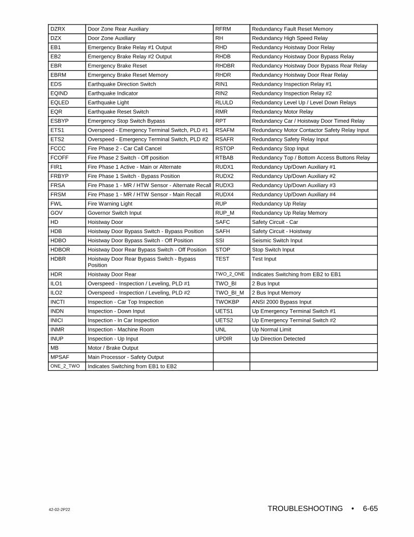
42-02-2P22 TROUBLESHOOTING • 6-65
DZRX Door Zone Rear Auxiliary RFRM Redundancy Fault Reset Memory
DZX Door Zone Auxiliary RH Redundancy High Speed Relay
EB1 Emergency Brake Relay #1 Output RHD Redundancy Hoistway Door Relay
EB2 Emergency Brake Relay #2 Output RHDB Redundancy Hoistway Door Bypass Relay
EBR Emergency Brake Reset RHDBR Redundancy Hoistway Door Bypass Rear Relay
EBRM Emergency Brake Reset Memory RHDR Redundancy Hoistway Door Rear Relay
EDS Earthquake Direction Switch RIN1 Redundancy Inspection Relay #1
EQIND Earthquake Indicator RIN2 Redundancy Inspection Relay #2
EQLED Earthquake Light RLULD Redundancy Level Up / Level Down Relays
EQR Earthquake Reset Switch RMR Redundancy Motor Relay
ESBYP Emergency Stop Switch Bypass RPT Redundancy Car / Hoistway Door Timed Relay
ETS1 Overspeed - Emergency Terminal Switch, PLD #1 RSAFM Redundancy Motor Contactor Safety Relay Input
ETS2 Overspeed - Emergency Terminal Switch, PLD #2 RSAFR Redundancy Safety Relay Input
FCCC Fire Phase 2 - Car Call Cancel RSTOP Redundancy Stop Input
FCOFF Fire Phase 2 Switch - Off position RTBAB Redundancy Top / Bottom Access Buttons Relay
FIR1 Fire Phase 1 Active - Main or Alternate RUDX1 Redundancy Up/Down Auxiliary #1
FRBYP Fire Phase 1 Switch - Bypass Position RUDX2 Redundancy Up/Down Auxiliary #2
FRSA Fire Phase 1 - MR / HTW Sensor - Alternate Recall RUDX3 Redundancy Up/Down Auxiliary #3
FRSM Fire Phase 1 - MR / HTW Sensor - Main Recall RUDX4 Redundancy Up/Down Auxiliary #4
FWL Fire Warning Light RUP Redundancy Up Relay
GOV Governor Switch Input RUP_M Redundancy Up Relay Memory
HD Hoistway Door SAFC Safety Circuit - Car
HDB Hoistway Door Bypass Switch - Bypass Position SAFH Safety Circuit - Hoistway
HDBO Hoistway Door Bypass Switch - Off Position SSI Seismic Switch Input
HDBOR Hoistway Door Rear Bypass Switch - Off Position STOP Stop Switch Input
HDBR Hoistway Door Rear Bypass Switch - BypassPosition
TEST Test Input
HDR Hoistway Door Rear TWO_2_ONE Indicates Switching from EB2 to EB1
ILO1 Overspeed - Inspection / Leveling, PLD #1 TWO_BI 2 Bus Input
ILO2 Overspeed - Inspection / Leveling, PLD #2 TWO_BI_M 2 Bus Input Memory
INCTI Inspection - Car Top Inspection TWOKBP ANSI 2000 Bypass Input
INDN Inspection - Down Input UETS1 Up Emergency Terminal Switch #1
INICI Inspection - In Car Inspection UETS2 Up Emergency Terminal Switch #2
INMR Inspection - Machine Room UNL Up Normal Limit
INUP Inspection - Up Input UPDIR Up Direction Detected
MB Motor / Brake Output
MPSAF Main Processor - Safety Output
ONE_2_TWO Indicates Switching from EB1 to EB2
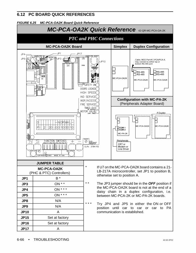
• TROUBLESHOOTING 42-02-2P226-66
6.12 PC BOARD QUICK REFERENCES
FIGURE 6.25 MC-PCA-OA2K Board Quick Reference
MC-PCA-OA2K Quick Reference 42-QR-MC-PCA-OA-2K
PTC and PHC Connections
MC-PCA-OA2K Board Simplex Duplex Configuration
Configuration with MC-PA-2K(Peripherals Adapter Board)
JUMPER TABLE* If U7 on the MC-PCA-OA2K board contains a 21-
LB-217A microcontroller, set JP1 to position B,otherwise set to position A.
* * The JP3 jumper should be in the OFF position ifthe MC-PCA-OA2K board is not at the end of adaisy chain in a duplex configuration, i.e.between MC-PCA-2K or MC-PA-2K boards.
* * * Try JP4 and JP5 in either the ON or OFFposition until car to car or car to PAcommunication is established.
MC-PCA-OA2K(PHC & PTC) Controllers)
JP1 B *
JP3 ON * *
JP4 ON * * *
JP5 ON * * *
JP8 N/A
JP9 N/A
JP10 A
JP15 Set at factory
JP16 Set at factory
JP17 A
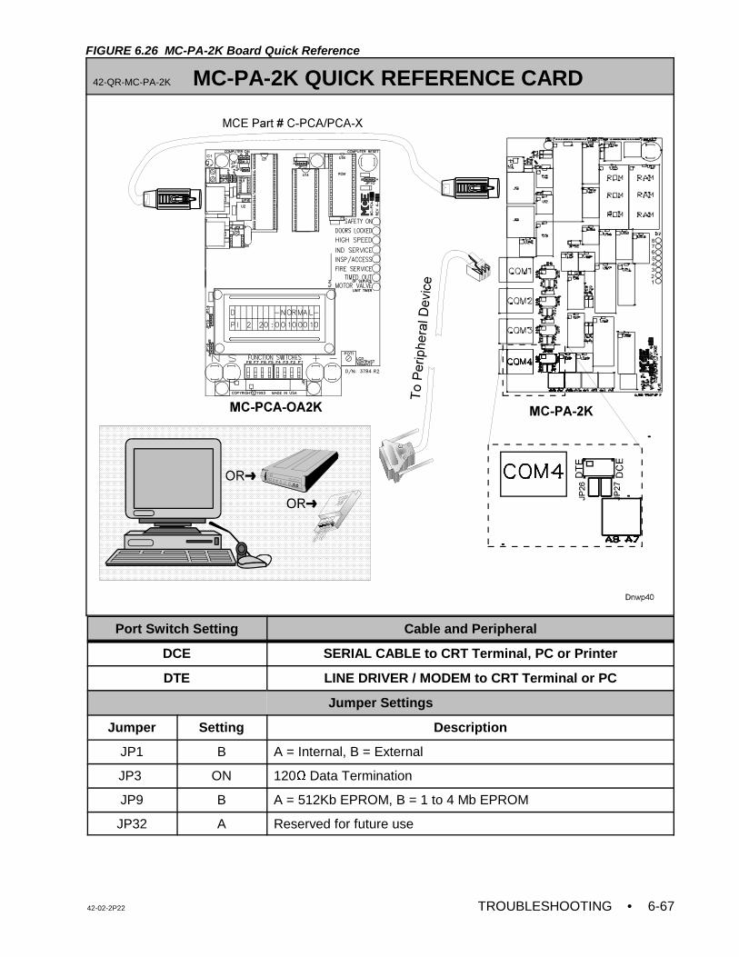
42-02-2P22 TROUBLESHOOTING • 6-67
FIGURE 6.26 MC-PA-2K Board Quick Reference
42-QR-MC-PA-2K MC-PA-2K QUICK REFERENCE CARD
Port Switch Setting Cable and Peripheral
DCE SERIAL CABLE to CRT Terminal, PC or Printer
DTE LINE DRIVER / MODEM to CRT Terminal or PC
Jumper Settings
Jumper Setting Description
JP1 B A = Internal, B = External
JP3 ON 120Ω Data Termination
JP9 B A = 512Kb EPROM, B = 1 to 4 Mb EPROM
JP32 A Reserved for future use
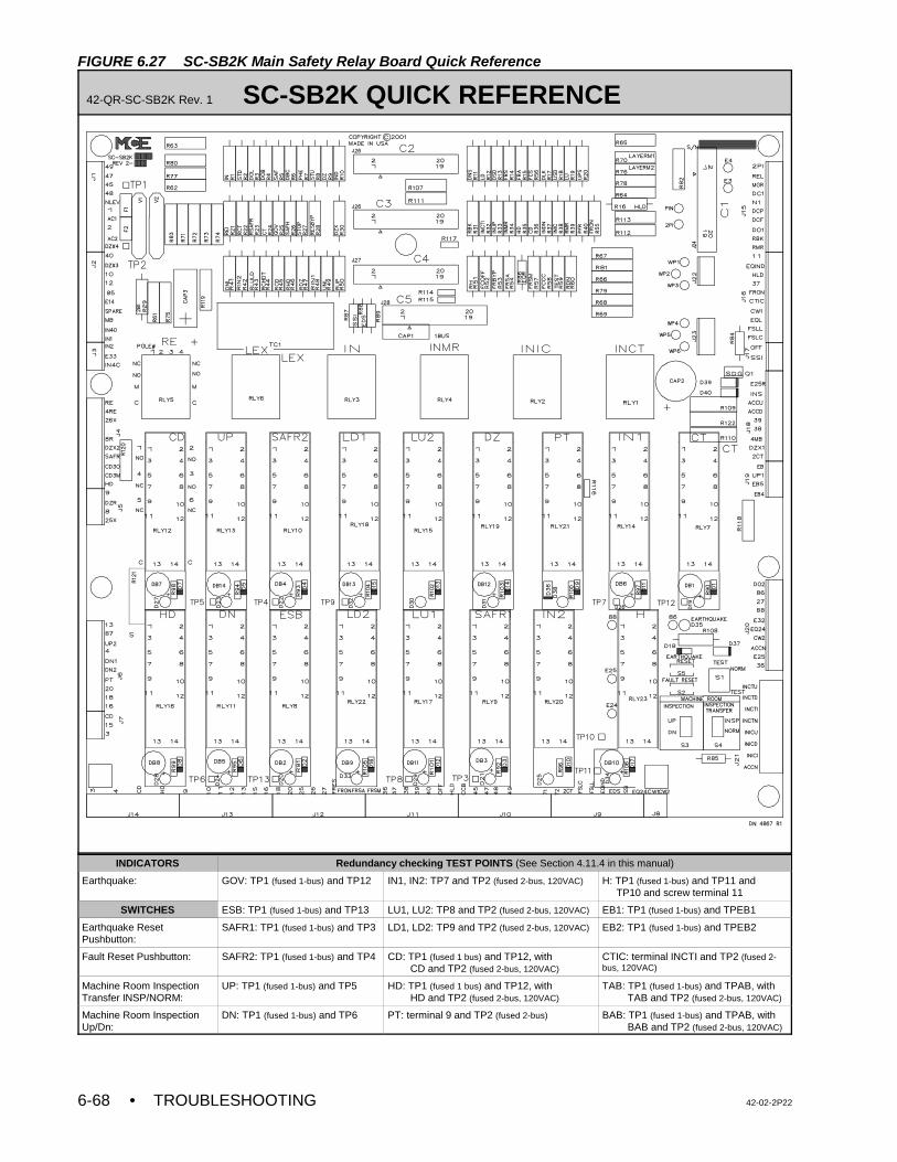
• TROUBLESHOOTING 42-02-2P226-68
FIGURE 6.27 SC-SB2K Main Safety Relay Board Quick Reference
42-QR-SC-SB2K Rev. 1 SC-SB2K QUICK REFERENCE
INDICATORS Redundancy checking TEST POINTS (See Section 4.11.4 in this manual)
Earthquake: GOV: TP1 (fused 1-bus) and TP12 IN1, IN2: TP7 and TP2 (fused 2-bus, 120VAC) H: TP1 (fused 1-bus) and TP11 and TP10 and screw terminal 11
SWITCHES ESB: TP1 (fused 1-bus) and TP13 LU1, LU2: TP8 and TP2 (fused 2-bus, 120VAC) EB1: TP1 (fused 1-bus) and TPEB1
Earthquake ResetPushbutton:
SAFR1: TP1 (fused 1-bus) and TP3 LD1, LD2: TP9 and TP2 (fused 2-bus, 120VAC) EB2: TP1 (fused 1-bus) and TPEB2
Fault Reset Pushbutton: SAFR2: TP1 (fused 1-bus) and TP4 CD: TP1 (fused 1 bus) and TP12, with CD and TP2 (fused 2-bus, 120VAC)
CTIC: terminal INCTI and TP2 (fused 2-bus, 120VAC)
Machine Room InspectionTransfer INSP/NORM:
UP: TP1 (fused 1-bus) and TP5 HD: TP1 (fused 1 bus) and TP12, with HD and TP2 (fused 2-bus, 120VAC)
TAB: TP1 (fused 1-bus) and TPAB, with TAB and TP2 (fused 2-bus, 120VAC)
Machine Room InspectionUp/Dn:
DN: TP1 (fused 1-bus) and TP6 PT: terminal 9 and TP2 (fused 2-bus) BAB: TP1 (fused 1-bus) and TPAB, with BAB and TP2 (fused 2-bus, 120VAC)
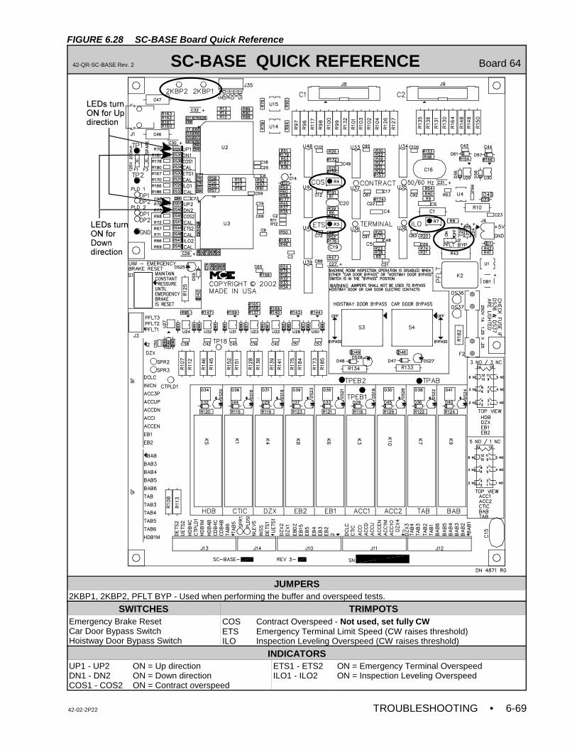
42-02-2P22 TROUBLESHOOTING • 6-69
FIGURE 6.28 SC-BASE Board Quick Reference
42-QR-SC-BASE Rev. 2 SC-BASE QUICK REFERENCE Board 64
JUMPERS2KBP1, 2KBP2, PFLT BYP - Used when performing the buffer and overspeed tests.
SWITCHES TRIMPOTSEmergency Brake ResetCar Door Bypass SwitchHoistway Door Bypass Switch
COS Contract Overspeed - Not used, set fully CWETS Emergency Terminal Limit Speed (CW raises threshold)ILO Inspection Leveling Overspeed (CW raises threshold)
INDICATORSUP1 - UP2DN1 - DN2COS1 - COS2
ON = Up directionON = Down directionON = Contract overspeed
ETS1 - ETS2ILO1 - ILO2
ON = Emergency Terminal OverspeedON = Inspection Leveling Overspeed
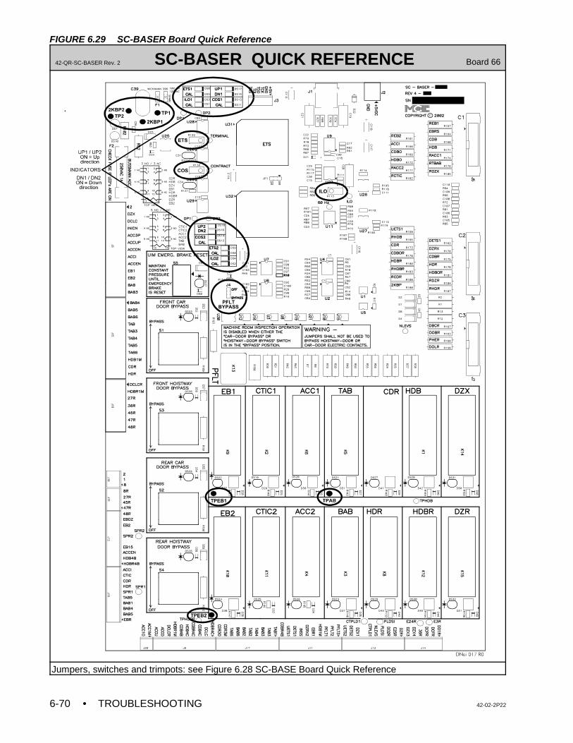
• TROUBLESHOOTING 42-02-2P226-70
FIGURE 6.29 SC-BASER Board Quick Reference
42-QR-SC-BASER Rev. 2 SC-BASER QUICK REFERENCE Board 66
Jumpers, switches and trimpots: see Figure 6.28 SC-BASE Board Quick Reference
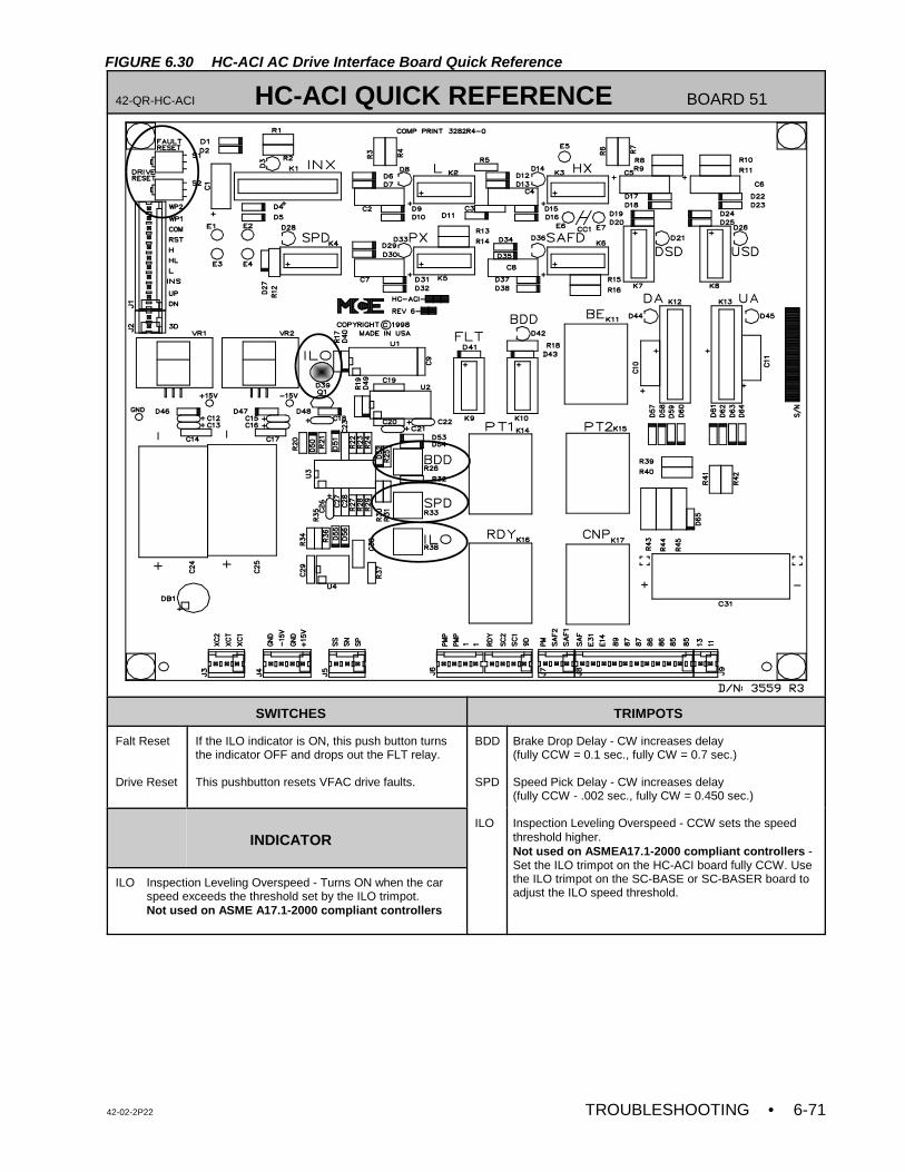
42-02-2P22 TROUBLESHOOTING • 6-71
FIGURE 6.30 HC-ACI AC Drive Interface Board Quick Reference
42-QR-HC-ACI HC-ACI QUICK REFERENCE BOARD 51
SWITCHES TRIMPOTS
Falt Reset
Drive Reset
If the ILO indicator is ON, this push button turnsthe indicator OFF and drops out the FLT relay.
This pushbutton resets VFAC drive faults.
BDD
SPD
ILO
Brake Drop Delay - CW increases delay(fully CCW = 0.1 sec., fully CW = 0.7 sec.)
Speed Pick Delay - CW increases delay (fully CCW - .002 sec., fully CW = 0.450 sec.)
Inspection Leveling Overspeed - CCW sets the speedthreshold higher. Not used on ASMEA17.1-2000 compliant controllers - Set the ILO trimpot on the HC-ACI board fully CCW. Usethe ILO trimpot on the SC-BASE or SC-BASER board toadjust the ILO speed threshold.
INDICATOR
ILO Inspection Leveling Overspeed - Turns ON when the carspeed exceeds the threshold set by the ILO trimpot.Not used on ASME A17.1-2000 compliant controllers
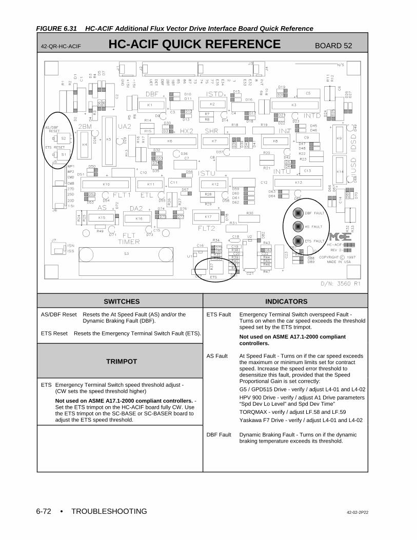
• TROUBLESHOOTING 42-02-2P226-72
FIGURE 6.31 HC-ACIF Additional Flux Vector Drive Interface Board Quick Reference
42-QR-HC-ACIF HC-ACIF QUICK REFERENCE BOARD 52
SWITCHES INDICATORS
AS/DBF Reset Resets the At Speed Fault (AS) and/or theDynamic Braking Fault (DBF).
ETS Reset Resets the Emergency Terminal Switch Fault (ETS).
ETS Fault Emergency Terminal Switch overspeed Fault -Turns on when the car speed exceeds the thresholdspeed set by the ETS trimpot.
Not used on ASME A17.1-2000 compliantcontrollers.
AS Fault At Speed Fault - Turns on if the car speed exceedsthe maximum or minimum limits set for contractspeed. Increase the speed error threshold todesensitize this fault, provided that the SpeedProportional Gain is set correctly:
G5 / GPD515 Drive - verify / adjust L4-01 and L4-02
HPV 900 Drive - verify / adjust A1 Drive parameters“Spd Dev Lo Level” and Spd Dev Time”
TORQMAX - verify / adjust LF.58 and LF.59
Yaskawa F7 Drive - verify / adjust L4-01 and L4-02
DBF Fault Dynamic Braking Fault - Turns on if the dynamicbraking temperature exceeds its threshold.
TRIMPOT
ETS Emergency Terminal Switch speed threshold adjust -(CW sets the speed threshold higher)
Not used on ASME A17.1-2000 compliant controllers. -Set the ETS trimpot on the HC-ACIF board fully CW. Usethe ETS trimpot on the SC-BASE or SC-BASER board toadjust the ETS speed threshold.
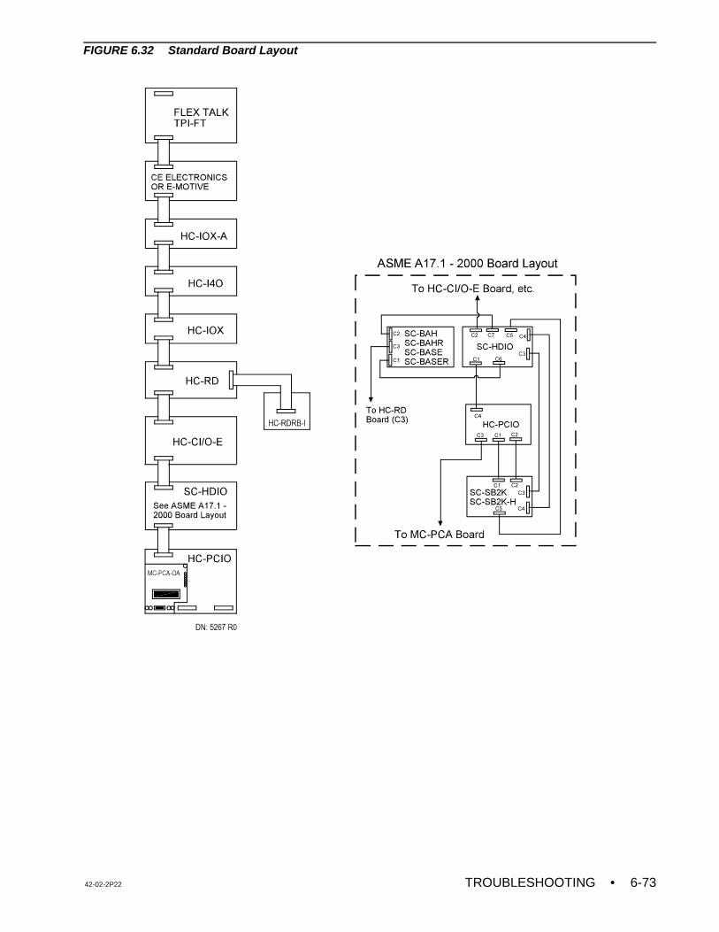
42-02-2P22 TROUBLESHOOTING • 6-73
FIGURE 6.32 Standard Board Layout


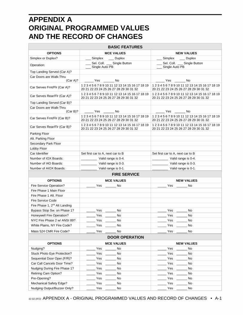
42-02-2P22 APPENDIX A - ORIGINAL PROGRAMMED VALUES AND RECORD OF CHANGES • A-1
APPENDIX AORIGINAL PROGRAMMED VALUESAND THE RECORD OF CHANGES
BASIC FEATURES
OPTIONS MCE VALUES NEW VALUES
Simplex or Duplex? ___ Simplex ___ Duplex ___ Simplex ___ Duplex
Operation: ___ Sel. Coll. ___ Single Button ___ Single Auto PB
___ Sel. Coll. ___ Single Button ___ Single Auto PB
Top Landing Served (Car A)?
Car Doors are Walk-Thru (Car A)? _____ Yes ______ No _____ Yes ______ No
Car Serves Frnt/Flr (Car A)?1 2 3 4 5 6 7 8 9 10 11 12 13 14 15 16 17 18 1920 21 22 23 24 25 26 27 28 29 30 31 32
1 2 3 4 5 6 7 8 9 10 11 12 13 14 15 16 17 18 1920 21 22 23 24 25 26 27 28 29 30 31 32
Car Serves Rear/Flr (Car A)?1 2 3 4 5 6 7 8 9 10 11 12 13 14 15 16 17 18 1920 21 22 23 24 25 26 27 28 29 30 31 32
1 2 3 4 5 6 7 8 9 10 11 12 13 14 15 16 17 18 1920 21 22 23 24 25 26 27 28 29 30 31 32
Top Landing Served (Car B)?
Car Doors are Walk-Thru (Car B)? _____ Yes ______ No _____ Yes ______ No
Car Serves Frnt/Flr (Car B)?1 2 3 4 5 6 7 8 9 10 11 12 13 14 15 16 17 18 1920 21 22 23 24 25 26 27 28 29 30 31 32
1 2 3 4 5 6 7 8 9 10 11 12 13 14 15 16 17 18 1920 21 22 23 24 25 26 27 28 29 30 31 32
Car Serves Rear/Flr (Car B)?1 2 3 4 5 6 7 8 9 10 11 12 13 14 15 16 17 18 1920 21 22 23 24 25 26 27 28 29 30 31 32
1 2 3 4 5 6 7 8 9 10 11 12 13 14 15 16 17 18 1920 21 22 23 24 25 26 27 28 29 30 31 32
Parking Floor
Alt. Parking Floor
Secondary Park Floor
Lobby Floor
Car Identifier Set first car to A, next car to B Set first car to A, next car to B
Number of IOX Boards: _________ Valid range is 0-4. _________ Valid range is 0-4.
Number of I4O Boards: _________ Valid range is 0-3. _________ Valid range is 0-3.
Number of AIOX Boards: _________ Valid range is 0-1. _________ Valid range is 0-1.
FIRE SERVICE
OPTIONS MCE VALUES NEW VALUES
Fire Service Operation? _____ Yes ______ No _____ Yes ______ No
Fire Phase 1 Main Floor
Fire Phase 1 Alt. Floor
Fire Service Code
Fire Phase 1, 2nd Alt Landing
Bypass Stop Sw. on Phase 1? _____ Yes ______ No _____ Yes ______ No
Honeywell Fire Operation? _____ Yes ______ No _____ Yes ______ No
NYC Fire Phase 2 w/ ANSI 89? _____ Yes ______ No _____ Yes ______ No
White Plains, NY Fire Code? _____ Yes ______ No _____ Yes ______ No
Mass 524 CMR Fire Code? _____ Yes ______ No _____ Yes ______ No
DOOR OPERATION
OPTIONS MCE VALUES NEW VALUES
Nudging? _____ Yes ______ No _____ Yes ______ No
Stuck Photo Eye Protection? _____ Yes ______ No _____ Yes ______ No
Sequential Door Oper.(F/R)? _____ Yes ______ No _____ Yes ______ No
Car Call Cancels Door Time? _____ Yes ______ No _____ Yes ______ No
Nudging During Fire Phase 1? _____ Yes ______ No _____ Yes ______ No
Retiring Cam Option? _____ Yes ______ No _____ Yes ______ No
Pre-Opening? _____ Yes ______ No _____ Yes ______ No
Mechanical Safety Edge? _____ Yes ______ No _____ Yes ______ No
Nudging Output/Buzzer Only? _____ Yes ______ No _____ Yes ______ No
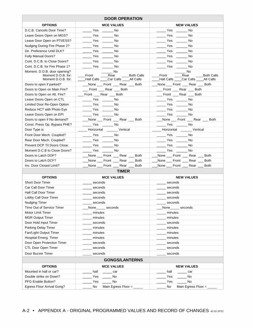
DOOR OPERATION
OPTIONS MCE VALUES NEW VALUES
• APPENDIX A - ORIGINAL PROGRAMMED VALUES AND RECORD OF CHANGES 42-02-2P22A-2
D.C.B. Cancels Door Time? _____ Yes ______ No _____ Yes ______ No
Leave Doors Open on MGS? _____ Yes ______ No _____ Yes ______ No
Leave Door Open on PTI/ESS? _____ Yes ______ No _____ Yes ______ No
Nudging During Fire Phase 2? _____ Yes ______ No _____ Yes ______ No
Dir. Preference Until DLK? _____ Yes ______ No _____ Yes ______ No
Fully Manual Doors? _____ Yes ______ No _____ Yes ______ No
Cont. D.C.B. to Close Doors? _____ Yes ______ No _____ Yes ______ No
Cont. D.C.B. for Fire Phase 1? _____ Yes ______ No _____ Yes ______ No
Moment. D.O.B. door opening? Moment D.O.B. for: Moment D.O.B. for:
______ No____Front ____Rear ____Both Calls____Hall Calls ____Car Calls ____All Calls
______ No____Front ____Rear ____Both Calls____Hall Calls ____Car Calls ____All Calls
Doors to open if parked? ___None ___ Front ___ Rear ___ Both ___None ___ Front ___ Rear ___ Both
Doors to Open on Main Fire? ___ Front ___ Rear ___ Both ___ Front ___ Rear ___ Both
Doors to Open on Alt. Fire? ___ Front ___ Rear ___ Both ___ Front ___ Rear ___ Both
Leave Doors Open on CTL _____ Yes ______ No _____ Yes ______ No
Limited Door Re-Open Option _____ Yes ______ No _____ Yes ______ No
Reduce HCT with Photo Eye _____ Yes ______ No _____ Yes ______ No
Leave Doors Open on EPI _____ Yes ______ No _____ Yes ______ No
Doors to open if No demand? ___None ___ Front ___ Rear ___ Both ___None ___ Front ___ Rear ___ Both
Const. Press Op. Bypass PHE? _____ Yes ______ No _____ Yes ______ No
Door Type is _____ Horizontal ______ Vertical _____ Horizontal ______ Vertical
Front Door Mech. Coupled? _____ Yes ______ No _____ Yes ______ No
Rear Door Mech. Coupled? _____ Yes ______ No _____ Yes ______ No
Prevent DCP Til Doors Close: _____ Yes ______ No _____ Yes ______ No
Moment D.C.B to Close Doors? _____ Yes ______ No _____ Yes ______ No
Doors to Latch DOF? ___None ___ Front ___ Rear ___ Both ___None ___ Front ___ Rear ___ Both
Doors to Latch DCF? ___None ___ Front ___ Rear ___ Both ___None ___ Front ___ Rear ___ Both
Inv. Door Closed Limit? ___None ___ Front ___ Rear ___ Both ___None ___ Front ___ Rear ___ Both
TIMEROPTIONS MCE VALUES NEW VALUES
Short Door Timer _____ seconds _____ seconds
Car Call Door Timer _____ seconds _____ seconds
Hall Call Door Timer _____ seconds _____ seconds
Lobby Call Door Timer _____ seconds _____ seconds
Nudging Timer _____ seconds _____ seconds
Time Out of Service Timer ___None_____ seconds ___None_____ seconds
Motor Limit Timer _____ minutes _____ minutes
MGR Output Timer _____ minutes _____ minutes
Door Hold Input Timer _____ seconds _____ seconds
Parking Delay Timer _____ minutes _____ minutes
Fan/Light Output Timer _____ minutes _____ minutes
Hospital Emerg. Timer _____ minutes _____ minutes
Door Open Protection Timer _____ seconds _____ seconds
CTL Door Open Timer _____ seconds _____ seconds
Door Buzzer Timer _____ seconds _____ seconds
GONGS/LANTERNS
OPTIONS MCE VALUES NEW VALUES
Mounted in hall or car? _____ hall _____ car _____ hall _____ car
Double strike on Down? _____ Yes _____ No _____ Yes _____ No
PFG Enable Button? _____ Yes _____ No _____ Yes _____ No
Egress Floor Arrival Gong? _____ No Main Egress Floor = _____ _____ No Main Egress Floor = _____
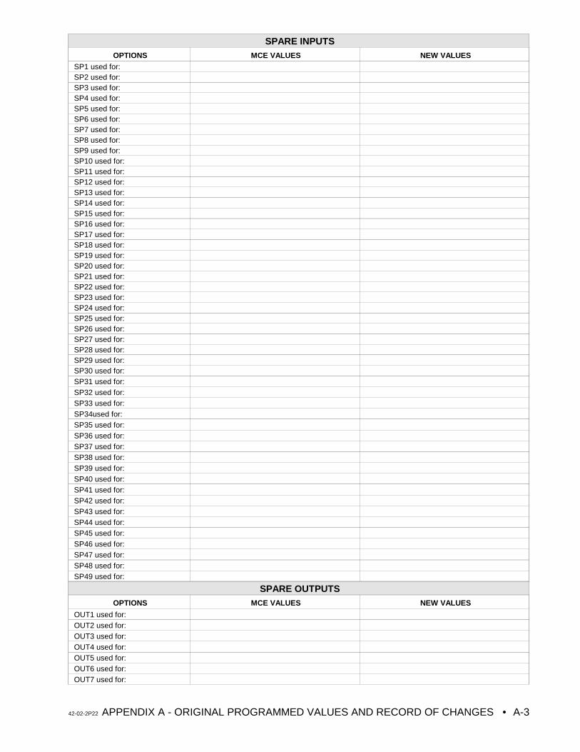
42-02-2P22 APPENDIX A - ORIGINAL PROGRAMMED VALUES AND RECORD OF CHANGES • A-3
SPARE INPUTSOPTIONS MCE VALUES NEW VALUES
SP1 used for:SP2 used for:SP3 used for:SP4 used for:SP5 used for:SP6 used for:SP7 used for:SP8 used for:SP9 used for:SP10 used for:SP11 used for:SP12 used for:SP13 used for:SP14 used for:SP15 used for:SP16 used for:SP17 used for:SP18 used for:SP19 used for:SP20 used for:SP21 used for:SP22 used for:SP23 used for:SP24 used for:SP25 used for:SP26 used for:SP27 used for:SP28 used for:SP29 used for:SP30 used for:SP31 used for:SP32 used for:SP33 used for:SP34used for:SP35 used for:SP36 used for:SP37 used for:SP38 used for:SP39 used for:SP40 used for:SP41 used for:SP42 used for:SP43 used for:SP44 used for:SP45 used for:SP46 used for:SP47 used for:SP48 used for:SP49 used for:
SPARE OUTPUTSOPTIONS MCE VALUES NEW VALUES
OUT1 used for:OUT2 used for:OUT3 used for:OUT4 used for:OUT5 used for:OUT6 used for:OUT7 used for:
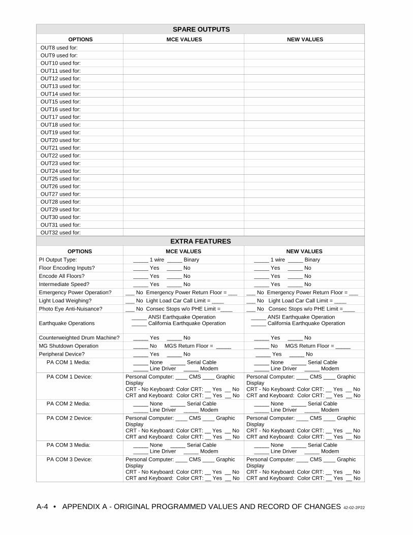
SPARE OUTPUTSOPTIONS MCE VALUES NEW VALUES
• APPENDIX A - ORIGINAL PROGRAMMED VALUES AND RECORD OF CHANGES 42-02-2P22A-4
OUT8 used for:OUT9 used for:OUT10 used for:OUT11 used for:OUT12 used for:OUT13 used for:OUT14 used for:OUT15 used for:OUT16 used for:OUT17 used for:OUT18 used for:OUT19 used for:OUT20 used for:OUT21 used for:OUT22 used for:OUT23 used for:OUT24 used for:OUT25 used for:OUT26 used for:OUT27 used for:OUT28 used for:OUT29 used for:OUT30 used for:OUT31 used for:OUT32 used for:
EXTRA FEATURESOPTIONS MCE VALUES NEW VALUES
PI Output Type: _____ 1 wire _____ Binary _____ 1 wire _____ Binary
Floor Encoding Inputs? _____ Yes _____ No _____ Yes _____ No
Encode All Floors? _____ Yes _____ No _____ Yes _____ No
Intermediate Speed? _____ Yes _____ No _____ Yes _____ No
Emergency Power Operation? ___ No Emergency Power Return Floor = ___ ___ No Emergency Power Return Floor = ___
Light Load Weighing? ___ No Light Load Car Call Limit = ____ ___ No Light Load Car Call Limit = ____
Photo Eye Anti-Nuisance? ___ No Consec Stops w/o PHE Limit =____ ___ No Consec Stops w/o PHE Limit =____
Earthquake Operations _____ ANSI Earthquake Operation _____ California Earthquake Operation
_____ ANSI Earthquake Operation _____ California Earthquake Operation
Counterweighted Drum Machine? _____ Yes _____ No _____ Yes _____ No
MG Shutdown Operation _____ No MGS Return Floor = _____ _____ No MGS Return Floor = _____
Peripheral Device? _____ Yes _____ No _____ Yes _____ No
PA COM 1 Media: _____ None _____ Serial Cable _____ Line Driver _____ Modem
_____ None _____ Serial Cable _____ Line Driver _____ Modem
PA COM 1 Device: Personal Computer: ____ CMS ____ GraphicDisplayCRT - No Keyboard: Color CRT: __ Yes __ NoCRT and Keyboard: Color CRT: __ Yes __ No
Personal Computer: ____ CMS ____ GraphicDisplayCRT - No Keyboard: Color CRT: __ Yes __ NoCRT and Keyboard: Color CRT: __ Yes __ No
PA COM 2 Media: _____ None _____ Serial Cable _____ Line Driver _____ Modem
_____ None _____ Serial Cable _____ Line Driver _____ Modem
PA COM 2 Device: Personal Computer: ____ CMS ____ GraphicDisplayCRT - No Keyboard: Color CRT: __ Yes __ NoCRT and Keyboard: Color CRT: __ Yes __ No
Personal Computer: ____ CMS ____ GraphicDisplayCRT - No Keyboard: Color CRT: __ Yes __ NoCRT and Keyboard: Color CRT: __ Yes __ No
PA COM 3 Media: _____ None _____ Serial Cable _____ Line Driver _____ Modem
_____ None _____ Serial Cable _____ Line Driver _____ Modem
PA COM 3 Device: Personal Computer: ____ CMS ____ GraphicDisplayCRT - No Keyboard: Color CRT: __ Yes __ NoCRT and Keyboard: Color CRT: __ Yes __ No
Personal Computer: ____ CMS ____ GraphicDisplayCRT - No Keyboard: Color CRT: __ Yes __ NoCRT and Keyboard: Color CRT: __ Yes __ No
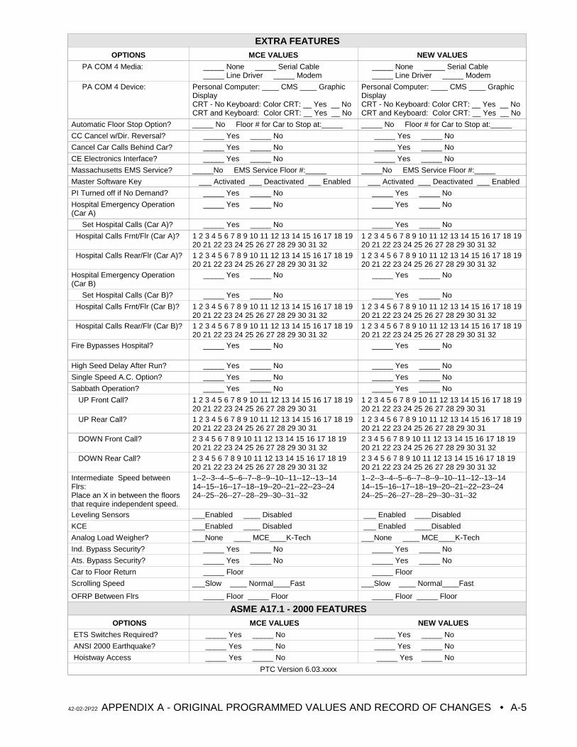
EXTRA FEATURESOPTIONS MCE VALUES NEW VALUES
42-02-2P22 APPENDIX A - ORIGINAL PROGRAMMED VALUES AND RECORD OF CHANGES • A-5
PA COM 4 Media: _____ None _____ Serial Cable _____ Line Driver _____ Modem
_____ None _____ Serial Cable _____ Line Driver _____ Modem
PA COM 4 Device: Personal Computer: ____ CMS ____ GraphicDisplayCRT - No Keyboard: Color CRT: __ Yes __ NoCRT and Keyboard: Color CRT: __ Yes __ No
Personal Computer: ____ CMS ____ GraphicDisplayCRT - No Keyboard: Color CRT: __ Yes __ NoCRT and Keyboard: Color CRT: __ Yes __ No
Automatic Floor Stop Option? _____ No Floor # for Car to Stop at:_____ _____ No Floor # for Car to Stop at:_____
CC Cancel w/Dir. Reversal? _____ Yes _____ No _____ Yes _____ No
Cancel Car Calls Behind Car? _____ Yes _____ No _____ Yes _____ No
CE Electronics Interface? _____ Yes _____ No _____ Yes _____ No
Massachusetts EMS Service? _____No EMS Service Floor #:_____ _____No EMS Service Floor #:_____
Master Software Key ___ Activated ___ Deactivated ___ Enabled ___ Activated ___ Deactivated ___ Enabled
PI Turned off if No Demand? _____ Yes _____ No _____ Yes _____ No
Hospital Emergency Operation(Car A)
_____ Yes _____ No _____ Yes _____ No
Set Hospital Calls (Car A)? _____ Yes _____ No _____ Yes _____ No
Hospital Calls Frnt/Flr (Car A)? 1 2 3 4 5 6 7 8 9 10 11 12 13 14 15 16 17 18 1920 21 22 23 24 25 26 27 28 29 30 31 32
1 2 3 4 5 6 7 8 9 10 11 12 13 14 15 16 17 18 1920 21 22 23 24 25 26 27 28 29 30 31 32
Hospital Calls Rear/Flr (Car A)? 1 2 3 4 5 6 7 8 9 10 11 12 13 14 15 16 17 18 1920 21 22 23 24 25 26 27 28 29 30 31 32
1 2 3 4 5 6 7 8 9 10 11 12 13 14 15 16 17 18 1920 21 22 23 24 25 26 27 28 29 30 31 32
Hospital Emergency Operation(Car B)
_____ Yes _____ No _____ Yes _____ No
Set Hospital Calls (Car B)? _____ Yes _____ No _____ Yes _____ No
Hospital Calls Frnt/Flr (Car B)? 1 2 3 4 5 6 7 8 9 10 11 12 13 14 15 16 17 18 1920 21 22 23 24 25 26 27 28 29 30 31 32
1 2 3 4 5 6 7 8 9 10 11 12 13 14 15 16 17 18 1920 21 22 23 24 25 26 27 28 29 30 31 32
Hospital Calls Rear/Flr (Car B)? 1 2 3 4 5 6 7 8 9 10 11 12 13 14 15 16 17 18 1920 21 22 23 24 25 26 27 28 29 30 31 32
1 2 3 4 5 6 7 8 9 10 11 12 13 14 15 16 17 18 1920 21 22 23 24 25 26 27 28 29 30 31 32
Fire Bypasses Hospital? _____ Yes _____ No _____ Yes _____ No
High Seed Delay After Run? _____ Yes _____ No _____ Yes _____ No
Single Speed A.C. Option? _____ Yes _____ No _____ Yes _____ No
Sabbath Operation? _____ Yes _____ No _____ Yes _____ No
UP Front Call? 1 2 3 4 5 6 7 8 9 10 11 12 13 14 15 16 17 18 1920 21 22 23 24 25 26 27 28 29 30 31
1 2 3 4 5 6 7 8 9 10 11 12 13 14 15 16 17 18 1920 21 22 23 24 25 26 27 28 29 30 31
UP Rear Call? 1 2 3 4 5 6 7 8 9 10 11 12 13 14 15 16 17 18 1920 21 22 23 24 25 26 27 28 29 30 31
1 2 3 4 5 6 7 8 9 10 11 12 13 14 15 16 17 18 1920 21 22 23 24 25 26 27 28 29 30 31
DOWN Front Call? 2 3 4 5 6 7 8 9 10 11 12 13 14 15 16 17 18 1920 21 22 23 24 25 26 27 28 29 30 31 32
2 3 4 5 6 7 8 9 10 11 12 13 14 15 16 17 18 1920 21 22 23 24 25 26 27 28 29 30 31 32
DOWN Rear Call? 2 3 4 5 6 7 8 9 10 11 12 13 14 15 16 17 18 1920 21 22 23 24 25 26 27 28 29 30 31 32
2 3 4 5 6 7 8 9 10 11 12 13 14 15 16 17 18 1920 21 22 23 24 25 26 27 28 29 30 31 32
Intermediate Speed betweenFlrs:Place an X in between the floorsthat require independent speed.
1--2--3--4--5--6--7--8--9--10--11--12--13--1414--15--16--17--18--19--20--21--22--23--2424--25--26--27--28--29--30--31--32
1--2--3--4--5--6--7--8--9--10--11--12--13--1414--15--16--17--18--19--20--21--22--23--2424--25--26--27--28--29--30--31--32
Leveling Sensors ___Enabled ____ Disabled ___ Enabled ____Disabled
KCE ___Enabled ____ Disabled ___ Enabled ____Disabled
Analog Load Weigher? ___None ____ MCE____K-Tech ___None ____ MCE____K-Tech
Ind. Bypass Security? _____ Yes _____ No _____ Yes _____ No
Ats. Bypass Security? _____ Yes _____ No _____ Yes _____ No
Car to Floor Return _____ Floor _____ Floor
Scrolling Speed ___Slow ____ Normal____Fast ___Slow ____ Normal____Fast
OFRP Between Flrs _____ Floor _____ Floor _____ Floor _____ Floor
ASME A17.1 - 2000 FEATURESOPTIONS MCE VALUES NEW VALUES
ETS Switches Required? _____ Yes _____ No _____ Yes _____ No
ANSI 2000 Earthquake? _____ Yes _____ No _____ Yes _____ No
Hoistway Access _____ Yes _____ No _____ Yes _____ No
PTC Version 6.03.xxxx
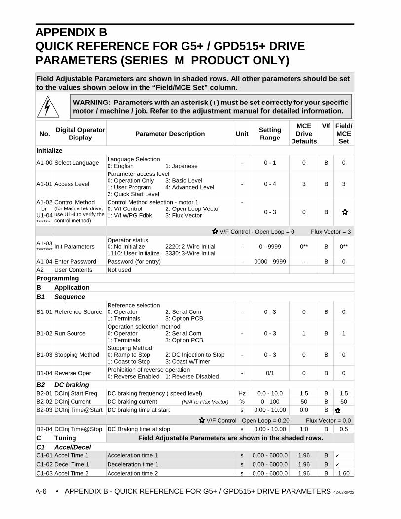
• APPENDIX B - QUICK REFERENCE FOR G5+ / GPD515+ DRIVE PARAMETERS 42-02-2P22A-6
WARNING: Parameters with an asterisk (u) must be set correctly for your specificmotor / machine / job. Refer to the adjustment manual for detailed information.
APPENDIX BQUICK REFERENCE FOR G5+ / GPD515+ DRIVEPARAMETERS (SERIES M PRODUCT ONLY)Field Adjustable Parameters are shown in shaded rows. All other parameters should be setto the values shown below in the “Field/MCE Set” column.
No. Digital OperatorDisplay
Parameter Description Unit SettingRange
MCEDrive
Defaults
V/f Field/MCESet
Initialize
A1-00 Select Language Language Selection0: English 1: Japanese - 0 - 1 0 B 0
A1-01 Access Level
Parameter access level0: Operation Only 3: Basic Level1: User Program 4: Advanced Level2: Quick Start Level
- 0 - 4 3 B 3
A1-02 or U1-04******
Control Method(for MagneTek drive,use U1-4 to verify thecontrol method)
Control Method selection - motor 10: V/f Control 2: Open Loop Vector1: V/f w/PG Fdbk 3: Flux Vector
-
0 - 3 0 B
V/F Control - Open Loop = 0 Flux Vector = 3
A1-03******* Inlt Parameters
Operator status0: No Initialize 2220: 2-Wire Initial1110: User Initialize 3330: 3-Wire Initial
- 0 - 9999 0** B 0**
A1-04 Enter Password Password (for entry) - 0000 - 9999 - B 0A2 User Contents Not used
ProgrammingB ApplicationB1 Sequence
B1-01 Reference SourceReference selection0: Operator 2: Serial Com1: Terminals 3: Option PCB
- 0 - 3 0 B 0
B1-02 Run SourceOperation selection method0: Operator 2: Serial Com1: Terminals 3: Option PCB
- 0 - 3 1 B 1
B1-03 Stopping MethodStopping Method0: Ramp to Stop 2: DC Injection to Stop1: Coast to Stop 3: Coast w/Timer
- 0 - 3 0 B 0
B1-04 Reverse Oper Prohibition of reverse operation0: Reverse Enabled 1: Reverse Disabled - 0/1 0 B 0
B2 DC brakingB2-01 DCInj Start Freq DC braking frequency ( speed level) Hz 0.0 - 10.0 1.5 B 1.5B2-02 DCInj Current DC braking current (N/A to Flux Vector) % 0 - 100 50 B 50B2-03 DCInj Time@Start DC braking time at start s 0.00 - 10.00 0.0 B
V/F Control - Open Loop = 0.20 Flux Vector = 0.0 B2-04 DCInj Time@Stop DC Braking time at stop s 0.00 - 10.00 1.0 B 0.5
C Tuning Field Adjustable Parameters are shown in the shaded rows.C1 Accel/DecelC1-01 Accel Time 1 Acceleration time 1 s 0.00 - 6000.0 1.96 B u
C1-02 Decel Time 1 Deceleration time 1 s 0.00 - 6000.0 1.96 B u
C1-03 Accel Time 2 Acceleration time 2 s 0.00 - 6000.0 1.96 B 1.60
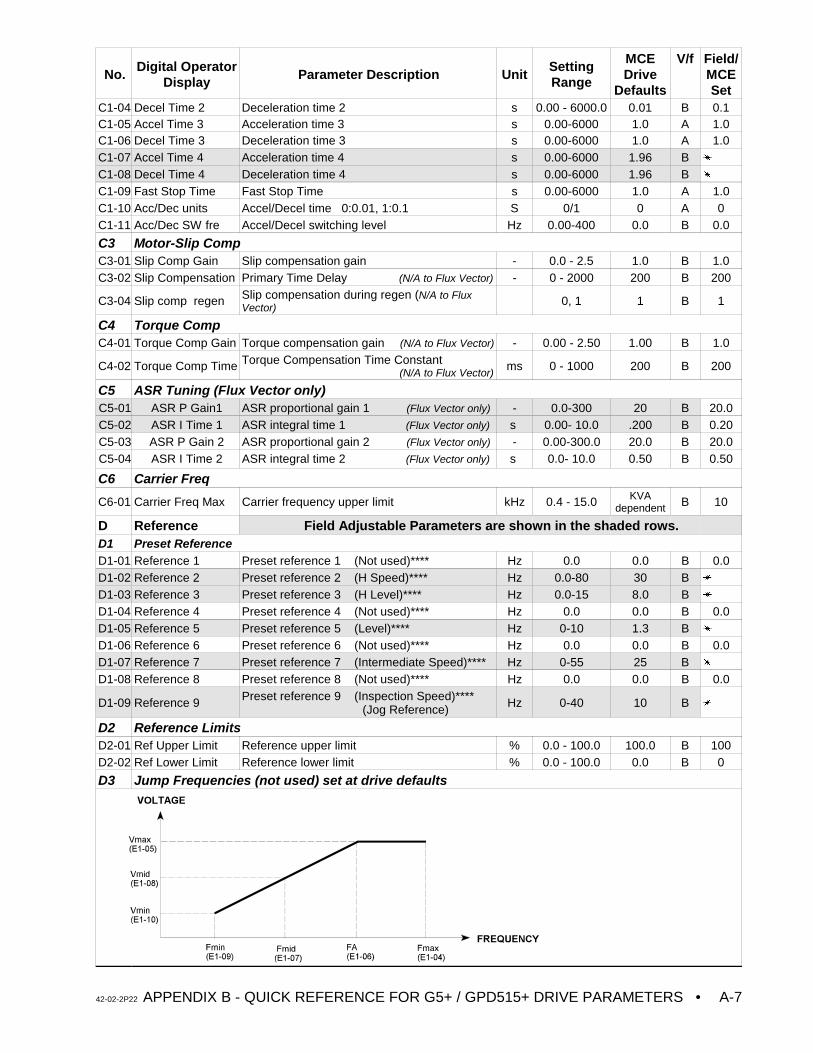
No.Digital Operator
Display Parameter Description UnitSettingRange
MCEDrive
Defaults
V/f Field/MCESet
42-02-2P22 APPENDIX B - QUICK REFERENCE FOR G5+ / GPD515+ DRIVE PARAMETERS • A-7
C1-04 Decel Time 2 Deceleration time 2 s 0.00 - 6000.0 0.01 B 0.1C1-05 Accel Time 3 Acceleration time 3 s 0.00-6000 1.0 A 1.0C1-06 Decel Time 3 Deceleration time 3 s 0.00-6000 1.0 A 1.0C1-07 Accel Time 4 Acceleration time 4 s 0.00-6000 1.96 B u
C1-08 Decel Time 4 Deceleration time 4 s 0.00-6000 1.96 B u
C1-09 Fast Stop Time Fast Stop Time s 0.00-6000 1.0 A 1.0C1-10 Acc/Dec units Accel/Decel time 0:0.01, 1:0.1 S 0/1 0 A 0C1-11 Acc/Dec SW fre Accel/Decel switching level Hz 0.00-400 0.0 B 0.0
C3 Motor-Slip CompC3-01 Slip Comp Gain Slip compensation gain - 0.0 - 2.5 1.0 B 1.0C3-02 Slip Compensation Primary Time Delay (N/A to Flux Vector) - 0 - 2000 200 B 200
C3-04 Slip comp regen Slip compensation during regen (N/A to FluxVector)
0, 1 1 B 1
C4 Torque CompC4-01 Torque Comp Gain Torque compensation gain (N/A to Flux Vector) - 0.00 - 2.50 1.00 B 1.0
C4-02 Torque Comp Time Torque Compensation Time Constant (N/A to Flux Vector)
ms 0 - 1000 200 B 200
C5 ASR Tuning (Flux Vector only)C5-01 ASR P Gain1 ASR proportional gain 1 (Flux Vector only) - 0.0-300 20 B 20.0C5-02 ASR I Time 1 ASR integral time 1 (Flux Vector only) s 0.00- 10.0 .200 B 0.20C5-03 ASR P Gain 2 ASR proportional gain 2 (Flux Vector only) - 0.00-300.0 20.0 B 20.0C5-04 ASR I Time 2 ASR integral time 2 (Flux Vector only) s 0.0- 10.0 0.50 B 0.50
C6 Carrier Freq
C6-01 Carrier Freq Max Carrier frequency upper limit kHz 0.4 - 15.0 KVAdependent B 10
D Reference Field Adjustable Parameters are shown in the shaded rows.D1 Preset ReferenceD1-01 Reference 1 Preset reference 1 (Not used)**** Hz 0.0 0.0 B 0.0D1-02 Reference 2 Preset reference 2 (H Speed)**** Hz 0.0-80 30 B u
D1-03 Reference 3 Preset reference 3 (H Level)**** Hz 0.0-15 8.0 B u
D1-04 Reference 4 Preset reference 4 (Not used)**** Hz 0.0 0.0 B 0.0D1-05 Reference 5 Preset reference 5 (Level)**** Hz 0-10 1.3 B u
D1-06 Reference 6 Preset reference 6 (Not used)**** Hz 0.0 0.0 B 0.0D1-07 Reference 7 Preset reference 7 (Intermediate Speed)**** Hz 0-55 25 B u
D1-08 Reference 8 Preset reference 8 (Not used)**** Hz 0.0 0.0 B 0.0
D1-09 Reference 9 Preset reference 9 (Inspection Speed)**** (Jog Reference) Hz 0-40 10 B u
D2 Reference LimitsD2-01 Ref Upper Limit Reference upper limit % 0.0 - 100.0 100.0 B 100D2-02 Ref Lower Limit Reference lower limit % 0.0 - 100.0 0.0 B 0
D3 Jump Frequencies (not used) set at drive defaults
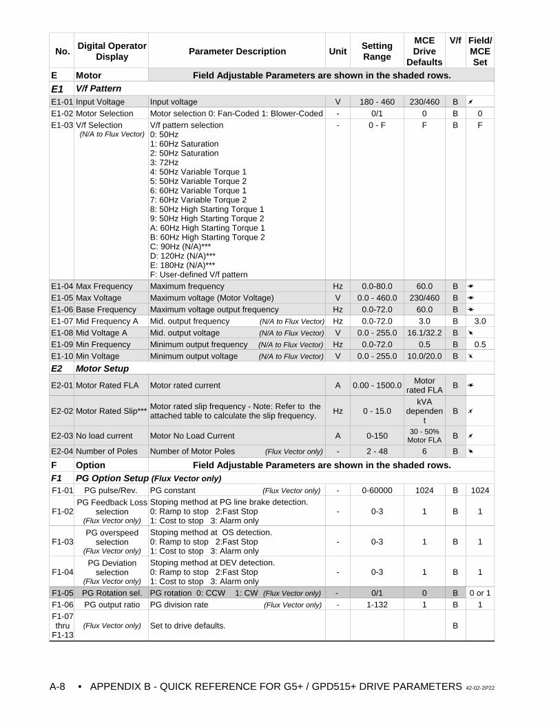
No.Digital Operator
Display Parameter Description UnitSettingRange
MCEDrive
Defaults
V/f Field/MCESet
• APPENDIX B - QUICK REFERENCE FOR G5+ / GPD515+ DRIVE PARAMETERS 42-02-2P22A-8
E Motor Field Adjustable Parameters are shown in the shaded rows.
E1 V/f PatternE1-01 Input Voltage Input voltage V 180 - 460 230/460 B u
E1-02 Motor Selection Motor selection 0: Fan-Coded 1: Blower-Coded - 0/1 0 B 0E1-03 V/f Selection
(N/A to Flux Vector)V/f pattern selection0: 50Hz1: 60Hz Saturation2: 50Hz Saturation3: 72Hz4: 50Hz Variable Torque 15: 50Hz Variable Torque 26: 60Hz Variable Torque 17: 60Hz Variable Torque 28: 50Hz High Starting Torque 19: 50Hz High Starting Torque 2A: 60Hz High Starting Torque 1B: 60Hz High Starting Torque 2C: 90Hz (N/A)***D: 120Hz (N/A)***E: 180Hz (N/A)***F: User-defined V/f pattern
- 0 - F F B F
E1-04 Max Frequency Maximum frequency Hz 0.0-80.0 60.0 B u
E1-05 Max Voltage Maximum voltage (Motor Voltage) V 0.0 - 460.0 230/460 B u
E1-06 Base Frequency Maximum voltage output frequency Hz 0.0-72.0 60.0 B u
E1-07 Mid Frequency A Mid. output frequency (N/A to Flux Vector) Hz 0.0-72.0 3.0 B 3.0E1-08 Mid Voltage A Mid. output voltage (N/A to Flux Vector) V 0.0 - 255.0 16.1/32.2 B u
E1-09 Min Frequency Minimum output frequency (N/A to Flux Vector) Hz 0.0-72.0 0.5 B 0.5E1-10 Min Voltage Minimum output voltage (N/A to Flux Vector) V 0.0 - 255.0 10.0/20.0 B u
E2 Motor Setup
E2-01 Motor Rated FLA Motor rated current A 0.00 - 1500.0 Motorrated FLA B u
E2-02 Motor Rated Slip*** Motor rated slip frequency - Note: Refer to theattached table to calculate the slip frequency. Hz 0 - 15.0
kVAdependen
tB u
E2-03 No load current Motor No Load Current A 0-150 30 - 50%Motor FLA B u
E2-04 Number of Poles Number of Motor Poles (Flux Vector only) - 2 - 48 6 B u
F Option Field Adjustable Parameters are shown in the shaded rows.F1 PG Option Setup (Flux Vector only)F1-01 PG pulse/Rev. PG constant (Flux Vector only) - 0-60000 1024 B 1024
F1-02PG Feedback Loss
selection(Flux Vector only)
Stoping method at PG line brake detection.0: Ramp to stop 2:Fast Stop1: Cost to stop 3: Alarm only
- 0-3 1 B 1
F1-03PG overspeed
selection(Flux Vector only)
Stoping method at OS detection.0: Ramp to stop 2:Fast Stop1: Cost to stop 3: Alarm only
- 0-3 1 B 1
F1-04PG Deviation
selection(Flux Vector only)
Stoping method at DEV detection.0: Ramp to stop 2:Fast Stop1: Cost to stop 3: Alarm only
- 0-3 1 B 1
F1-05 PG Rotation sel. PG rotation 0: CCW 1: CW (Flux Vector only) - 0/1 0 B 0 or 1F1-06 PG output ratio PG division rate (Flux Vector only) - 1-132 1 B 1F1-07thru
F1-13(Flux Vector only) Set to drive defaults. B
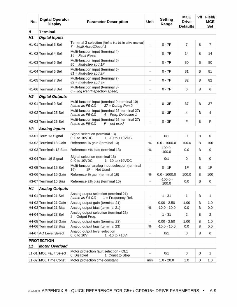
No.Digital Operator
Display Parameter Description UnitSettingRange
MCEDrive
Defaults
V/f Field/MCESet
42-02-2P22 APPENDIX B - QUICK REFERENCE FOR G5+ / GPD515+ DRIVE PARAMETERS • A-9
H TerminalH1 Digital Inputs
H1-01 Terminal 3 Sel Terminal 3 selection (Ref to H1-01 in drive manual)7 = Multi Accel/Decel 1 - 0 - 7F 7 B 7
H1-02 Terminal 4 Sel Multi-function input (terminal 4)14 = Fault Reset - 0 - 7F 14 B 14
H1-03 Terminal 5 Sel Multi-function input (terminal 5)80 = Mult-step spd 1F - 0 - 7F 80 B 80
H1-04 Terminal 6 Sel Multi-function input (terminal 6)81 = Mult-step spd 2F - 0 - 7F 81 B 81
H1-05 Terminal 7 Sel Multi-function input (terminal 7)82 = mult-step spd 3F - 0 - 7F 82 B 82
H1-06 Terminal 8 Sel Multi-function input (terminal 8)6 = Jog Ref (Inspection speed) - 0 - 7F 6 B 6
H2 Digital Outputs
H2-01 Terminal 9 Sel Multi-function input (terminal 9, terminal 10)(same as F5-01) 37 = During Run 2 - 0 - 3F 37 B 37
H2-02 Terminal 25 Sel Multi-function input (terminal 25, terminal 27)(same as F5-01) 4 = Freq. Detection 1 - 0 - 3F 4 B 4
H2-03 Terminal 26 Sel Multi-function input (terminal 26, terminal 27)(same as F5-01) F = not used - 0 - 3F F B F
H3 Analog Inputs
H3-01 Term 13 Signal Signal selection (terminal 13)0: 0 to 10VDC 1: -10 to +10VDC - 0/1 0 B 0
H3-02 Terminal 13 Gain Reference % gain (terminal 13) % 0.0 - 1000.0 100.0 B 100
H3-03 Terminals 13 Bias Reference ±% bias (terminal 13) % -100.0 -100.0 0.0 B 0
H3-04 Term 16 Signal Signal selection (terminal 16)0: 0 to 10VDC 1: -10 to +10VDC - 0/1 0 B 0
H3-05 Terminal 16 Sel Multi-function analog input selection (terminal16) 1F = Not Used - 0 - 1F 1F B 1F
H3-06 Terminal 16 Gain Reference % gain (terminal 16) % 0.0 - 1000.0 100.0 B 100
H3-07 Terminal 16 Bias Reference ±% bias (terminal 16) - -100.0 -100.0 0.0 B 0
H4 Analog Outputs
H4-01 Terminal 21 Sel Analog output selection (terminal 21)(same as F4-01) 1 = Frequency Ref. - 1 - 31 1 B 1
H4-02 Terminal 21 Gain Analog output gain (terminal 21) - 0.00 - 2.50 1.00 B 1.0H4-03 Terminal 21 Bias Analog output bias (terminal 21) % -10.0 - 10.0 0.0 B 0.0
H4-04 Terminal 23 Sel Analog output selection (terminal 23)2 = Output Freq. - 1 - 31 2 B 2
H4-05 Terminal 23 Gain Analog output gain (terminal 23) - 0.00 - 2.50 1.00 B 1.0H4-06 Terminal 23 Bias Analog output bias (terminal 23) % -10.0 - 10.0 0.0 B 0.0
H4-07 AO Level Select Analog output level selection0: 0 to 10V 1: -10 to +10V - 0/1 0 B 0
PROTECTIONL1 Motor Overload
L1-01 MOL Fault Select Motor protection fault selection - OL10: Disabled 1: Coast to Stop - 0/1 0 B 1
L1-02 MOL Time Const Motor protection time constant min 1.0 - 20.0 1.0 B 1.0
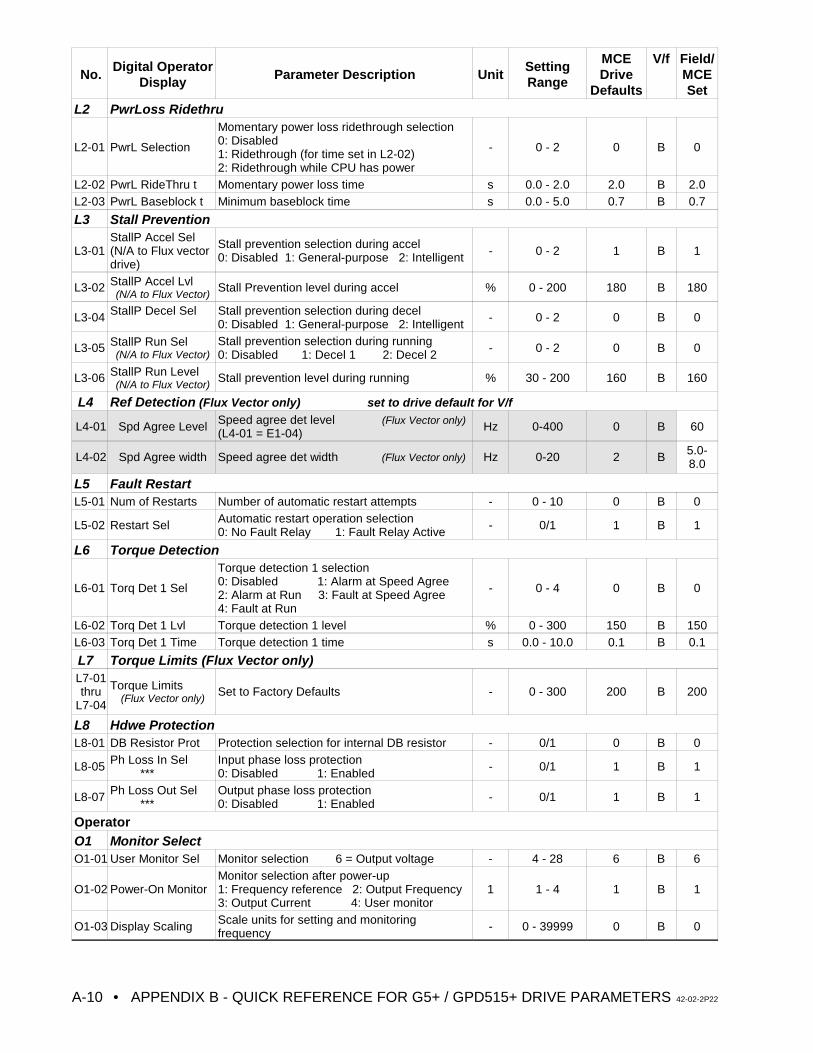
No.Digital Operator
Display Parameter Description UnitSettingRange
MCEDrive
Defaults
V/f Field/MCESet
• APPENDIX B - QUICK REFERENCE FOR G5+ / GPD515+ DRIVE PARAMETERS 42-02-2P22A-10
L2 PwrLoss Ridethru
L2-01 PwrL Selection
Momentary power loss ridethrough selection0: Disabled1: Ridethrough (for time set in L2-02)2: Ridethrough while CPU has power
- 0 - 2 0 B 0
L2-02 PwrL RideThru t Momentary power loss time s 0.0 - 2.0 2.0 B 2.0L2-03 PwrL Baseblock t Minimum baseblock time s 0.0 - 5.0 0.7 B 0.7
L3 Stall Prevention
L3-01StallP Accel Sel(N/A to Flux vectordrive)
Stall prevention selection during accel0: Disabled 1: General-purpose 2: Intelligent - 0 - 2 1 B 1
L3-02 StallP Accel Lvl(N/A to Flux Vector)
Stall Prevention level during accel % 0 - 200 180 B 180
L3-04 StallP Decel Sel Stall prevention selection during decel0: Disabled 1: General-purpose 2: Intelligent - 0 - 2 0 B 0
L3-05 StallP Run Sel(N/A to Flux Vector)
Stall prevention selection during running0: Disabled 1: Decel 1 2: Decel 2 - 0 - 2 0 B 0
L3-06 StallP Run Level(N/A to Flux Vector)
Stall prevention level during running % 30 - 200 160 B 160
L4 Ref Detection (Flux Vector only) set to drive default for V/f
L4-01 Spd Agree Level Speed agree det level (Flux Vector only)(L4-01 = E1-04) Hz 0-400 0 B 60
L4-02 Spd Agree width Speed agree det width (Flux Vector only) Hz 0-20 2 B 5.0-8.0
L5 Fault RestartL5-01 Num of Restarts Number of automatic restart attempts - 0 - 10 0 B 0
L5-02 Restart Sel Automatic restart operation selection0: No Fault Relay 1: Fault Relay Active - 0/1 1 B 1
L6 Torque Detection
L6-01 Torq Det 1 Sel
Torque detection 1 selection0: Disabled 1: Alarm at Speed Agree 2: Alarm at Run 3: Fault at Speed Agree4: Fault at Run
- 0 - 4 0 B 0
L6-02 Torq Det 1 Lvl Torque detection 1 level % 0 - 300 150 B 150L6-03 Torq Det 1 Time Torque detection 1 time s 0.0 - 10.0 0.1 B 0.1
L7 Torque Limits (Flux Vector only)L7-01thru
L7-04
Torque Limits(Flux Vector only)
Set to Factory Defaults - 0 - 300 200 B 200
L8 Hdwe ProtectionL8-01 DB Resistor Prot Protection selection for internal DB resistor - 0/1 0 B 0
L8-05 Ph Loss In Sel ***
Input phase loss protection0: Disabled 1: Enabled - 0/1 1 B 1
L8-07 Ph Loss Out Sel ***
Output phase loss protection0: Disabled 1: Enabled - 0/1 1 B 1
OperatorO1 Monitor SelectO1-01 User Monitor Sel Monitor selection 6 = Output voltage - 4 - 28 6 B 6
O1-02 Power-On MonitorMonitor selection after power-up1: Frequency reference 2: Output Frequency3: Output Current 4: User monitor
1 1 - 4 1 B 1
O1-03 Display Scaling Scale units for setting and monitoringfrequency - 0 - 39999 0 B 0
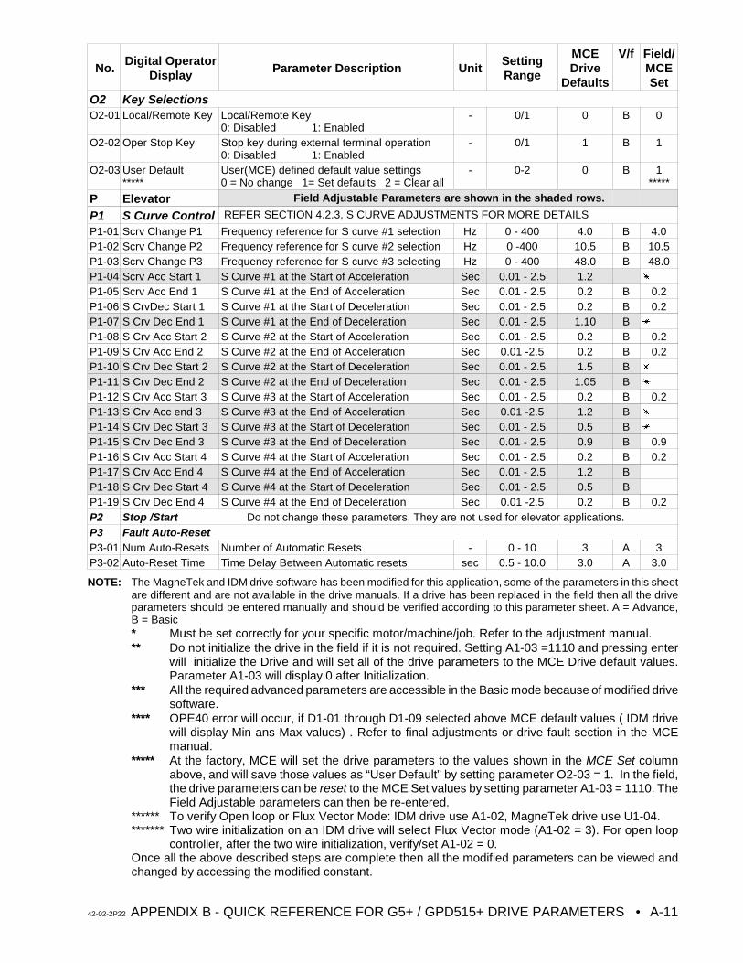
No.Digital Operator
Display Parameter Description UnitSettingRange
MCEDrive
Defaults
V/f Field/MCESet
42-02-2P22 APPENDIX B - QUICK REFERENCE FOR G5+ / GPD515+ DRIVE PARAMETERS • A-11
O2 Key SelectionsO2-01 Local/Remote Key Local/Remote Key
0: Disabled 1: Enabled- 0/1 0 B 0
O2-02 Oper Stop Key Stop key during external terminal operation0: Disabled 1: Enabled
- 0/1 1 B 1
O2-03 User Default*****
User(MCE) defined default value settings0 = No change 1= Set defaults 2 = Clear all
- 0-2 0 B 1*****
P Elevator Field Adjustable Parameters are shown in the shaded rows.
P1 S Curve Control REFER SECTION 4.2.3, S CURVE ADJUSTMENTS FOR MORE DETAILS
P1-01 Scrv Change P1 Frequency reference for S curve #1 selection Hz 0 - 400 4.0 B 4.0P1-02 Scrv Change P2 Frequency reference for S curve #2 selection Hz 0 -400 10.5 B 10.5P1-03 Scrv Change P3 Frequency reference for S curve #3 selecting Hz 0 - 400 48.0 B 48.0P1-04 Scrv Acc Start 1 S Curve #1 at the Start of Acceleration Sec 0.01 - 2.5 1.2 u
P1-05 Scrv Acc End 1 S Curve #1 at the End of Acceleration Sec 0.01 - 2.5 0.2 B 0.2P1-06 S CrvDec Start 1 S Curve #1 at the Start of Deceleration Sec 0.01 - 2.5 0.2 B 0.2P1-07 S Crv Dec End 1 S Curve #1 at the End of Deceleration Sec 0.01 - 2.5 1.10 B u
P1-08 S Crv Acc Start 2 S Curve #2 at the Start of Acceleration Sec 0.01 - 2.5 0.2 B 0.2P1-09 S Crv Acc End 2 S Curve #2 at the End of Acceleration Sec 0.01 -2.5 0.2 B 0.2P1-10 S Crv Dec Start 2 S Curve #2 at the Start of Deceleration Sec 0.01 - 2.5 1.5 B u
P1-11 S Crv Dec End 2 S Curve #2 at the End of Deceleration Sec 0.01 - 2.5 1.05 B u
P1-12 S Crv Acc Start 3 S Curve #3 at the Start of Acceleration Sec 0.01 - 2.5 0.2 B 0.2P1-13 S Crv Acc end 3 S Curve #3 at the End of Acceleration Sec 0.01 -2.5 1.2 B u
P1-14 S Crv Dec Start 3 S Curve #3 at the Start of Deceleration Sec 0.01 - 2.5 0.5 B u
P1-15 S Crv Dec End 3 S Curve #3 at the End of Deceleration Sec 0.01 - 2.5 0.9 B 0.9P1-16 S Crv Acc Start 4 S Curve #4 at the Start of Acceleration Sec 0.01 - 2.5 0.2 B 0.2P1-17 S Crv Acc End 4 S Curve #4 at the End of Acceleration Sec 0.01 - 2.5 1.2 BP1-18 S Crv Dec Start 4 S Curve #4 at the Start of Deceleration Sec 0.01 - 2.5 0.5 BP1-19 S Crv Dec End 4 S Curve #4 at the End of Deceleration Sec 0.01 -2.5 0.2 B 0.2P2 Stop /Start Do not change these parameters. They are not used for elevator applications.P3 Fault Auto-ResetP3-01 Num Auto-Resets Number of Automatic Resets - 0 - 10 3 A 3P3-02 Auto-Reset Time Time Delay Between Automatic resets sec 0.5 - 10.0 3.0 A 3.0
NOTE: The MagneTek and IDM drive software has been modified for this application, some of the parameters in this sheetare different and are not available in the drive manuals. If a drive has been replaced in the field then all the driveparameters should be entered manually and should be verified according to this parameter sheet. A = Advance,B = Basic* Must be set correctly for your specific motor/machine/job. Refer to the adjustment manual.** Do not initialize the drive in the field if it is not required. Setting A1-03 =1110 and pressing enter
will initialize the Drive and will set all of the drive parameters to the MCE Drive default values.Parameter A1-03 will display 0 after Initialization.
*** All the required advanced parameters are accessible in the Basic mode because of modified drivesoftware.
**** OPE40 error will occur, if D1-01 through D1-09 selected above MCE default values ( IDM drivewill display Min ans Max values) . Refer to final adjustments or drive fault section in the MCEmanual.
***** At the factory, MCE will set the drive parameters to the values shown in the MCE Set columnabove, and will save those values as “User Default” by setting parameter O2-03 = 1. In the field,the drive parameters can be reset to the MCE Set values by setting parameter A1-03 = 1110. TheField Adjustable parameters can then be re-entered.
****** To verify Open loop or Flux Vector Mode: IDM drive use A1-02, MagneTek drive use U1-04. ******* Two wire initialization on an IDM drive will select Flux Vector mode (A1-02 = 3). For open loop
controller, after the two wire initialization, verify/set A1-02 = 0.Once all the above described steps are complete then all the modified parameters can be viewed andchanged by accessing the modified constant.
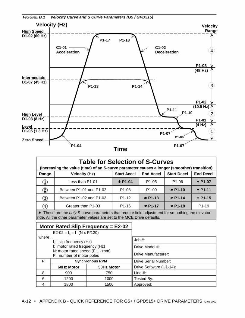
• APPENDIX B - QUICK REFERENCE FOR G5+ / GPD515+ DRIVE PARAMETERS 42-02-2P22A-12
Velocity (Hz)
Time
Zero Speed
Level D1-05 (1.3 Hz)
High LevelD1-03 (8 Hz)
IntermediateD1-07 (45 Hz)
High SpeedD1-02 (60 Hz)
P1-04
C1-01 Acceleration
C1-02 Deceleration
P1-13 P1-14
P1-11P1-10
P1-07P1-06
P1-07
P1-17 P1-18
P1-03 (48 Hz)
P1-02 (10.5 Hz)
P1-01 (4 Hz)
1
2
3
4
VelocityRange
FIGURE B.1 Velocity Curve and S Curve Parameters (G5 / GPD515)
Table for Selection of S-Curves(Increasing the value (time) of an S-curve parameter causes a longer (smoother) transition)Range Velocity (Hz) Start Accel End Accel Start Decel End Decel
Î Less than P1-01 w P1-04 P1-05 P1-06 w P1-07
Ï Between P1-01 and P1-02 P1-08 P1-09 w P1-10 w P1-11
Ð Between P1-02 and P1-03 P1-12 w P1-13 w P1-14 w P1-15
Ñ Greater than P1-03 P1-16 w P1-17 w P1-18 P1-19
w These are the only S-curve parameters that require field adjustment for smoothing the elevatorride. All the other parameter values are set to the MCE Drive defaults.
Motor Rated Slip Frequency = E2-02E2-02 = fs = f!(N x P/120)
where...fs: slip frequency (Hz)f: motor rated frequency (Hz)N: motor rated speed (F.L - rpm)P: number of motor poles
Job #:
Drive Model #:
Drive Manufacturer:
P Synchronous RPM Drive Serial Number:
60Hz Motor 50Hz Motor Drive Software (U1-14):
8 900 750 Line #:6 1200 1000 Tested By:4 1800 1500 Approved:
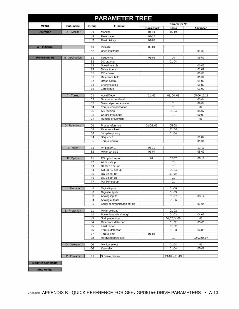
42-02-2P22 APPENDIX B - QUICK REFERENCE FOR G5+ / GPD515+ DRIVE PARAMETERS • A-13
PARAMETER TREEMENU Sub-menu Group Function
Parameter No.Quick-start Basic Advanced
Operation U Monitor U1 Monitor 01-14 15-19
U2 Fault trace 01-14U3 Fault history 01-08
A Initialize A1 Initialize 00-04
A2 User constants 01-32
Programming B Application B1 Sequence 01-03 04 05-07
B2 DC braking 01-04B3 Speed search 01-03B4 Delay timers 01,02B5 PID control 01-08B6 Reference hold 01-04B7 Droop control 01,02B8 Energy saving 01,02B9 Zero servo 01,02
C Tuning C1 Accel/Decel 01, 02 03, 04, 09 05-06,10,11C2 S-curve accel/decel 01-04C3 Motor slip compensation 01 02-04C4 Torque compensation 01 02C5 ASR tuning 01-04 05-07C6 Carrier frequency 01 02,03C7 Hunting prevention 01
D Reference D1 Preset reference 01-04, 09 05-08D2 Reference limit 01, 02D3 Jump frequency 01-04D4 Sequence 01,02D5 Torque control 01-04
E Motor E1 V/f pattern 1 01-10 11-13E2 Motor set-up 1 01-04 05-09
F Option F1 PG option set-up 01 02-07 08-13F2 AI-14 set-up 01F3 DI-08, 16 set-up 01F4 AO-08, 12 set-up 01-04F5 DO-02 set-up 01, 02F6 DO-08 set up 01F7 PO-36F set up 01
H Terminal H1 Digital inputs 01-06H2 Digital outputs 01-03H3 Analog inputs 01-07 08-12H4 Analog outputs 01-06H5 Serial communication set-up 01-04
L Protection L1 Motor overbad 01-02L2 Power loss ride through 01-03 04,05L3 Stall prevention 01,02,04-06 03L4 Reference detection 01,02 03-05L5 Fault restart 01,02L6 Torque detection 01-03 04,05L7 Torque limit 01-04L8 Hardware protection 01 02,03,05,07
O Operator O1 Monitor select 01-04 05O2 Key select 01-04 05-08
P Elevator P1 S Curve Control P1-01 - P1-19
Modified Constants
Auto-tuning
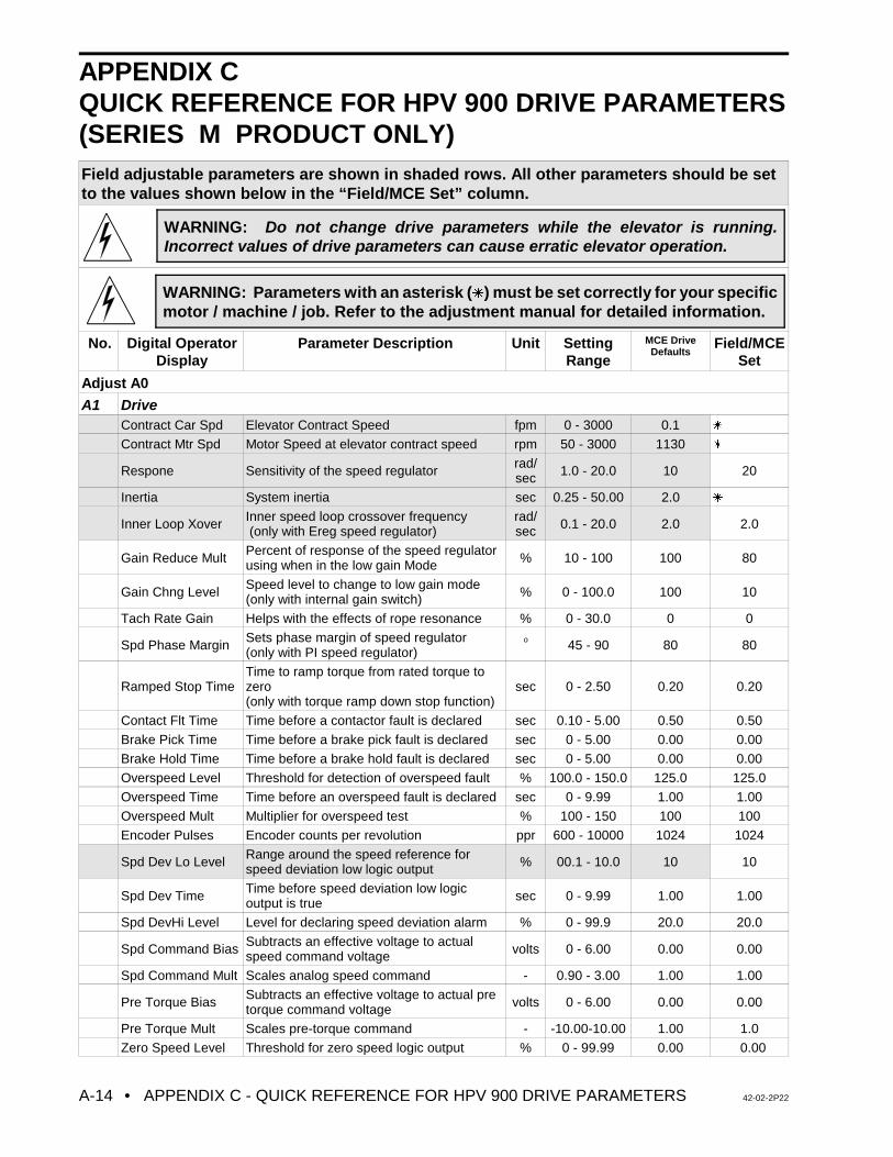
• APPENDIX C - QUICK REFERENCE FOR HPV 900 DRIVE PARAMETERS 42-02-2P22A-14
WARNING: Do not change drive parameters while the elevator is running.Incorrect values of drive parameters can cause erratic elevator operation.
WARNING: Parameters with an asterisk (u) must be set correctly for your specificmotor / machine / job. Refer to the adjustment manual for detailed information.
APPENDIX CQUICK REFERENCE FOR HPV 900 DRIVE PARAMETERS(SERIES M PRODUCT ONLY)Field adjustable parameters are shown in shaded rows. All other parameters should be setto the values shown below in the “Field/MCE Set” column.
No. Digital OperatorDisplay
Parameter Description Unit SettingRange
MCE DriveDefaults
Field/MCESet
Adjust A0
A1 DriveContract Car Spd Elevator Contract Speed fpm 0 - 3000 0.1 u
Contract Mtr Spd Motor Speed at elevator contract speed rpm 50 - 3000 1130 u
Respone Sensitivity of the speed regulator rad/sec 1.0 - 20.0 10 20
Inertia System inertia sec 0.25 - 50.00 2.0 u
Inner Loop Xover Inner speed loop crossover frequency (only with Ereg speed regulator)
rad/sec 0.1 - 20.0 2.0 2.0
Gain Reduce Mult Percent of response of the speed regulatorusing when in the low gain Mode % 10 - 100 100 80
Gain Chng Level Speed level to change to low gain mode(only with internal gain switch) % 0 - 100.0 100 10
Tach Rate Gain Helps with the effects of rope resonance % 0 - 30.0 0 0
Spd Phase Margin Sets phase margin of speed regulator(only with PI speed regulator)
o 45 - 90 80 80
Ramped Stop TimeTime to ramp torque from rated torque tozero(only with torque ramp down stop function)
sec 0 - 2.50 0.20 0.20
Contact Flt Time Time before a contactor fault is declared sec 0.10 - 5.00 0.50 0.50
Brake Pick Time Time before a brake pick fault is declared sec 0 - 5.00 0.00 0.00
Brake Hold Time Time before a brake hold fault is declared sec 0 - 5.00 0.00 0.00
Overspeed Level Threshold for detection of overspeed fault % 100.0 - 150.0 125.0 125.0
Overspeed Time Time before an overspeed fault is declared sec 0 - 9.99 1.00 1.00
Overspeed Mult Multiplier for overspeed test % 100 - 150 100 100
Encoder Pulses Encoder counts per revolution ppr 600 - 10000 1024 1024
Spd Dev Lo Level Range around the speed reference forspeed deviation low logic output % 00.1 - 10.0 10 10
Spd Dev Time Time before speed deviation low logicoutput is true sec 0 - 9.99 1.00 1.00
Spd DevHi Level Level for declaring speed deviation alarm % 0 - 99.9 20.0 20.0
Spd Command Bias Subtracts an effective voltage to actualspeed command voltage volts 0 - 6.00 0.00 0.00
Spd Command Mult Scales analog speed command - 0.90 - 3.00 1.00 1.00
Pre Torque Bias Subtracts an effective voltage to actual pretorque command voltage volts 0 - 6.00 0.00 0.00
Pre Torque Mult Scales pre-torque command - -10.00-10.00 1.00 1.0
Zero Speed Level Threshold for zero speed logic output % 0 - 99.99 0.00 0.00
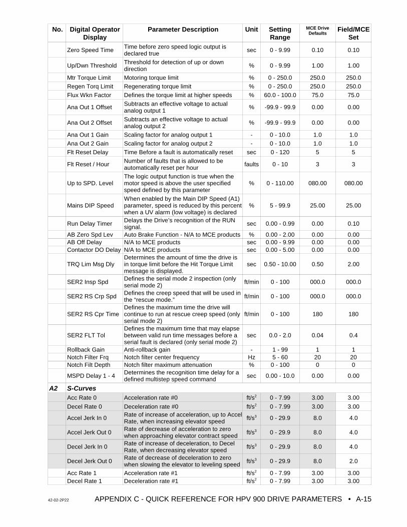
No. Digital OperatorDisplay
Parameter Description Unit SettingRange
MCE DriveDefaults
Field/MCESet
42-02-2P22 APPENDIX C - QUICK REFERENCE FOR HPV 900 DRIVE PARAMETERS • A-15
Zero Speed Time Time before zero speed logic output isdeclared true sec 0 - 9.99 0.10 0.10
Up/Dwn Threshold Threshold for detection of up or downdirection % 0 - 9.99 1.00 1.00
Mtr Torque Limit Motoring torque limit % 0 - 250.0 250.0 250.0
Regen Torq Limit Regenerating torque limit % 0 - 250.0 250.0 250.0
Flux Wkn Factor Defines the torque limit at higher speeds % 60.0 - 100.0 75.0 75.0
Ana Out 1 Offset Subtracts an effective voltage to actualanalog output 1 % -99.9 - 99.9 0.00 0.00
Ana Out 2 Offset Subtracts an effective voltage to actualanalog output 2 % -99.9 - 99.9 0.00 0.00
Ana Out 1 Gain Scaling factor for analog output 1 - 0 - 10.0 1.0 1.0
Ana Out 2 Gain Scaling factor for analog output 2 - 0 - 10.0 1.0 1.0
Flt Reset Delay Time Before a fault is automatically reset sec 0 - 120 5 5
Flt Reset / Hour Number of faults that is allowed to beautomatically reset per hour faults 0 - 10 3 3
Up to SPD. LevelThe logic output function is true when themotor speed is above the user specifiedspeed defined by this parameter
% 0 - 110.00 080.00 080.00
Mains DIP SpeedWhen enabled by the Main DIP Speed (A1)parameter, speed is reduced by this percentwhen a UV alarm (low voltage) is declared
% 5 - 99.9 25.00 25.00
Run Delay Timer Delays the Drive’s recognition of the RUNsignal. sec 0.00 - 0.99 0.00 0.10
AB Zero Spd Lev Auto Brake Function - N/A to MCE products % 0.00 - 2.00 0.00 0.00AB Off Delay N/A to MCE products sec 0.00 - 9.99 0.00 0.00Contactor DO Delay N/A to MCE products sec 0.00 - 5.00 0.00 0.00
TRQ Lim Msg DlyDetermines the amount of time the drive isin torque limit before the Hit Torque Limitmessage is displayed.
sec 0.50 - 10.00 0.50 2.00
SER2 Insp Spd Defines the serial mode 2 inspection (onlyserial mode 2) ft/min 0 - 100 000.0 000.0
SER2 RS Crp Spd Defines the creep speed that will be used inthe “rescue mode.” ft/min 0 - 100 000.0 000.0
SER2 RS Cpr TimeDefines the maximum time the drive willcontinue to run at rescue creep speed (onlyserial mode 2)
ft/min 0 - 100 180 180
SER2 FLT TolDefines the maximum time that may elapsebetween valid run time messages before aserial fault is declared (only serial mode 2)
sec 0.0 - 2.0 0.04 0.4
Rollback Gain Anti-rollback gain - 1 - 99 1 1Notch Filter Frq Notch filter center frequency Hz 5 - 60 20 20Notch Filt Depth Notch filter maximum attenuation % 0 - 100 0 0
MSPD Delay 1 - 4 Determines the recognition time delay for adefined multistep speed command sec 0.00 - 10.0 0.00 0.00
A2 S-CurvesAcc Rate 0 Acceleration rate #0 ft/s2 0 - 7.99 3.00 3.00
Decel Rate 0 Deceleration rate #0 ft/s2 0 - 7.99 3.00 3.00
Accel Jerk In 0 Rate of increase of acceleration, up to AccelRate, when increasing elevator speed ft/s3 0 - 29.9 8.0 4.0
Accel Jerk Out 0 Rate of decrease of acceleration to zerowhen approaching elevator contract speed ft/s3 0 - 29.9 8.0 4.0
Decel Jerk In 0 Rate of increase of deceleration, to DecelRate, when decreasing elevator speed ft/s3 0 - 29.9 8.0 4.0
Decel Jerk Out 0 Rate of decrease of deceleration to zerowhen slowing the elevator to leveling speed ft/s3 0 - 29.9 8.0 2.0
Acc Rate 1 Acceleration rate #1 ft/s2 0 - 7.99 3.00 3.00Decel Rate 1 Deceleration rate #1 ft/s2 0 - 7.99 3.00 3.00
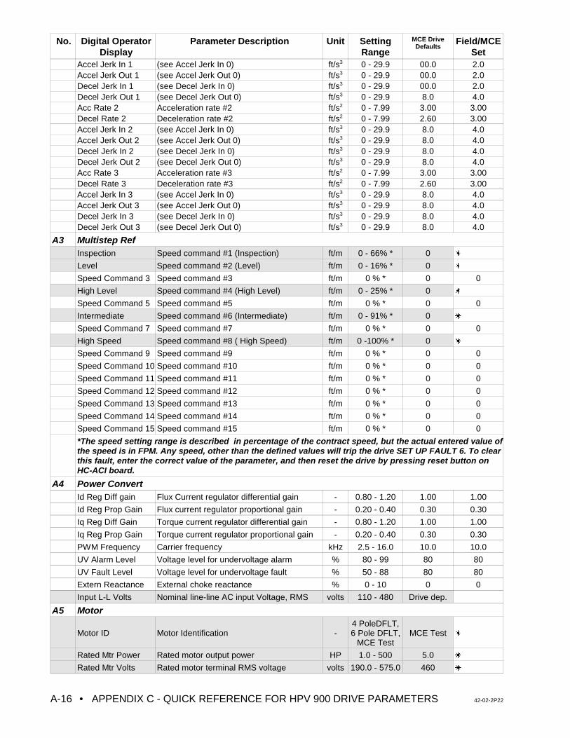
No. Digital OperatorDisplay
Parameter Description Unit SettingRange
MCE DriveDefaults
Field/MCESet
• APPENDIX C - QUICK REFERENCE FOR HPV 900 DRIVE PARAMETERS 42-02-2P22A-16
Accel Jerk In 1 (see Accel Jerk In 0) ft/s3 0 - 29.9 00.0 2.0Accel Jerk Out 1 (see Accel Jerk Out 0) ft/s3 0 - 29.9 00.0 2.0Decel Jerk In 1 (see Decel Jerk In 0) ft/s3 0 - 29.9 00.0 2.0Decel Jerk Out 1 (see Decel Jerk Out 0) ft/s3 0 - 29.9 8.0 4.0Acc Rate 2 Acceleration rate #2 ft/s2 0 - 7.99 3.00 3.00Decel Rate 2 Deceleration rate #2 ft/s2 0 - 7.99 2.60 3.00Accel Jerk In 2 (see Accel Jerk In 0) ft/s3 0 - 29.9 8.0 4.0Accel Jerk Out 2 (see Accel Jerk Out 0) ft/s3 0 - 29.9 8.0 4.0Decel Jerk In 2 (see Decel Jerk In 0) ft/s3 0 - 29.9 8.0 4.0Decel Jerk Out 2 (see Decel Jerk Out 0) ft/s3 0 - 29.9 8.0 4.0Acc Rate 3 Acceleration rate #3 ft/s2 0 - 7.99 3.00 3.00Decel Rate 3 Deceleration rate #3 ft/s2 0 - 7.99 2.60 3.00Accel Jerk In 3 (see Accel Jerk In 0) ft/s3 0 - 29.9 8.0 4.0Accel Jerk Out 3 (see Accel Jerk Out 0) ft/s3 0 - 29.9 8.0 4.0Decel Jerk In 3 (see Decel Jerk In 0) ft/s3 0 - 29.9 8.0 4.0Decel Jerk Out 3 (see Decel Jerk Out 0) ft/s3 0 - 29.9 8.0 4.0
A3 Multistep RefInspection Speed command #1 (Inspection) ft/m 0 - 66% * 0 u
Level Speed command #2 (Level) ft/m 0 - 16% * 0 u
Speed Command 3 Speed command #3 ft/m 0 % * 0 0
High Level Speed command #4 (High Level) ft/m 0 - 25% * 0 u
Speed Command 5 Speed command #5 ft/m 0 % * 0 0
Intermediate Speed command #6 (Intermediate) ft/m 0 - 91% * 0 u
Speed Command 7 Speed command #7 ft/m 0 % * 0 0
High Speed Speed command #8 ( High Speed) ft/m 0 -100% * 0 u
Speed Command 9 Speed command #9 ft/m 0 % * 0 0
Speed Command 10 Speed command #10 ft/m 0 % * 0 0
Speed Command 11 Speed command #11 ft/m 0 % * 0 0
Speed Command 12 Speed command #12 ft/m 0 % * 0 0
Speed Command 13 Speed command #13 ft/m 0 % * 0 0
Speed Command 14 Speed command #14 ft/m 0 % * 0 0
Speed Command 15 Speed command #15 ft/m 0 % * 0 0
*The speed setting range is described in percentage of the contract speed, but the actual entered value ofthe speed is in FPM. Any speed, other than the defined values will trip the drive SET UP FAULT 6. To clearthis fault, enter the correct value of the parameter, and then reset the drive by pressing reset button onHC-ACI board.
A4 Power ConvertId Reg Diff gain Flux Current regulator differential gain - 0.80 - 1.20 1.00 1.00
Id Reg Prop Gain Flux current regulator proportional gain - 0.20 - 0.40 0.30 0.30
Iq Reg Diff Gain Torque current regulator differential gain - 0.80 - 1.20 1.00 1.00
Iq Reg Prop Gain Torque current regulator proportional gain - 0.20 - 0.40 0.30 0.30
PWM Frequency Carrier frequency kHz 2.5 - 16.0 10.0 10.0
UV Alarm Level Voltage level for undervoltage alarm % 80 - 99 80 80
UV Fault Level Voltage level for undervoltage fault % 50 - 88 80 80
Extern Reactance External choke reactance % 0 - 10 0 0
Input L-L Volts Nominal line-line AC input Voltage, RMS volts 110 - 480 Drive dep.
A5 Motor
Motor ID Motor Identification -4 PoleDFLT,6 Pole DFLT,
MCE TestMCE Test u
Rated Mtr Power Rated motor output power HP 1.0 - 500 5.0 u
Rated Mtr Volts Rated motor terminal RMS voltage volts 190.0 - 575.0 460 u
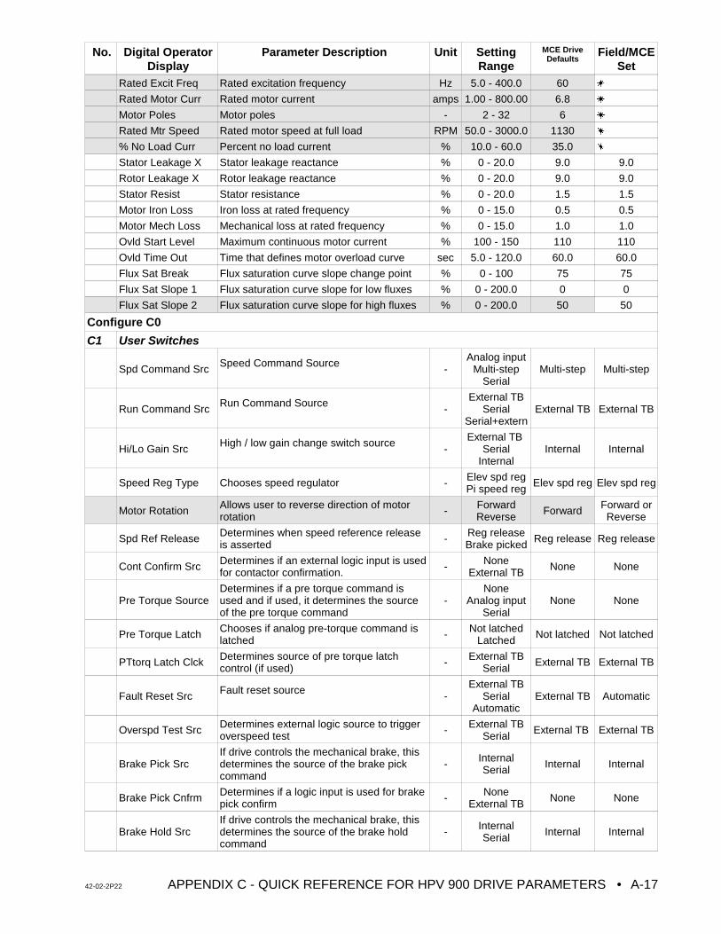
No. Digital OperatorDisplay
Parameter Description Unit SettingRange
MCE DriveDefaults
Field/MCESet
42-02-2P22 APPENDIX C - QUICK REFERENCE FOR HPV 900 DRIVE PARAMETERS • A-17
Rated Excit Freq Rated excitation frequency Hz 5.0 - 400.0 60 u
Rated Motor Curr Rated motor current amps 1.00 - 800.00 6.8 u
Motor Poles Motor poles - 2 - 32 6 u
Rated Mtr Speed Rated motor speed at full load RPM 50.0 - 3000.0 1130 u
% No Load Curr Percent no load current % 10.0 - 60.0 35.0 u
Stator Leakage X Stator leakage reactance % 0 - 20.0 9.0 9.0
Rotor Leakage X Rotor leakage reactance % 0 - 20.0 9.0 9.0
Stator Resist Stator resistance % 0 - 20.0 1.5 1.5
Motor Iron Loss Iron loss at rated frequency % 0 - 15.0 0.5 0.5
Motor Mech Loss Mechanical loss at rated frequency % 0 - 15.0 1.0 1.0
Ovld Start Level Maximum continuous motor current % 100 - 150 110 110
Ovld Time Out Time that defines motor overload curve sec 5.0 - 120.0 60.0 60.0
Flux Sat Break Flux saturation curve slope change point % 0 - 100 75 75
Flux Sat Slope 1 Flux saturation curve slope for low fluxes % 0 - 200.0 0 0
Flux Sat Slope 2 Flux saturation curve slope for high fluxes % 0 - 200.0 50 50
Configure C0
C1 User Switches
Spd Command Src Speed Command Source -Analog input
Multi-stepSerial
Multi-step Multi-step
Run Command Src Run Command Source -External TB
SerialSerial+extern
External TB External TB
Hi/Lo Gain Src High / low gain change switch source -External TB
SerialInternal
Internal Internal
Speed Reg Type Chooses speed regulator - Elev spd regPi speed reg Elev spd reg Elev spd reg
Motor Rotation Allows user to reverse direction of motorrotation - Forward
Reverse Forward Forward orReverse
Spd Ref Release Determines when speed reference releaseis asserted - Reg release
Brake picked Reg release Reg release
Cont Confirm Src Determines if an external logic input is usedfor contactor confirmation. - None
External TB None None
Pre Torque SourceDetermines if a pre torque command isused and if used, it determines the sourceof the pre torque command
-None
Analog inputSerial
None None
Pre Torque Latch Chooses if analog pre-torque command islatched - Not latched
Latched Not latched Not latched
PTtorq Latch Clck Determines source of pre torque latchcontrol (if used) - External TB
Serial External TB External TB
Fault Reset Src Fault reset source -External TB
SerialAutomatic
External TB Automatic
Overspd Test Src Determines external logic source to triggeroverspeed test - External TB
Serial External TB External TB
Brake Pick SrcIf drive controls the mechanical brake, thisdetermines the source of the brake pickcommand
- InternalSerial Internal Internal
Brake Pick Cnfrm Determines if a logic input is used for brakepick confirm - None
External TB None None
Brake Hold SrcIf drive controls the mechanical brake, thisdetermines the source of the brake holdcommand
- InternalSerial Internal Internal
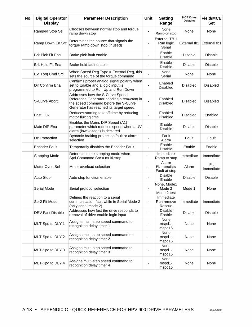
No. Digital OperatorDisplay
Parameter Description Unit SettingRange
MCE DriveDefaults
Field/MCESet
• APPENDIX C - QUICK REFERENCE FOR HPV 900 DRIVE PARAMETERS 42-02-2P22A-18
Ramped Stop Sel Chooses between normal stop and torqueramp down stop - None
Ramp on stopNone None
Ramp Down En Src Determines the source that signals thetorque ramp down stop (if used) -
External TB 1Run logic
SerialExternal tb1 External tb1
Brk Pick Flt Ena Brake pick fault enable - EnableDisable Disable Disable
Brk Hold Flt Ena Brake hold fault enable - EnableDisable Disable Disable
Ext Torq Cmd Src When Speed Reg Type = External Reg, thissets the source of the torque command - None
Serial None None
Dir Confirm EnaConfirms proper analog signal polarity whenset to Enable and a logic input isprogrammed to Run Up and Run Down
- EnabledDisabled Disabled Disabled
S-Curve Abort
Addresses how the S-Curve SpeedReference Generator handles a reduction inthe speed command before the S-CurveGenerator has reached its target speed.
- EnabledDisabled Disabled Disabled
Fast Flux Reduces starting takeoff time by reducingmotor fluxing time - Enabled
Disabled Disabled Enabled
Main DIP EnaEnables the Mains DIP Speed (A1)parameter which reduces speed when a UValarm (low voltage) is declared
- EnableDisable Disable Disable
DB Protection Dynamic braking protection fault or alarmselection - Fault
Alarm Fault Fault
Encoder Fault Temporarily disables the Encoder Fault - EnableDisable Enable Enable
Stopping Mode Determines the stopping mode when Spd Command Src = multi-step - Immediate
Ramp to stop Immediate Immediate
Motor Ovrld Sel Motor overload selection -Alarm
Flt ImmediateFault at stop
Alarm FltImmediate
Auto Stop Auto stop function enable - DisableEnable Disable Disable
Serial Mode Serial protocol selection -None, Mode1
Mode 2Mode 2 test
Mode 1 None
Ser2 Flt ModeDefines the reaction to a serialcommunication fault while in Serial Mode 2(only serial mode 2)
-Immediate
Run removeRescue
Immediate Immediate
DRV Fast Disable Addresses how fast the drive responds toremoval of drive enable logic input - Disable
Enable Disable Disable
MLT-Spd to DLY 1 Assigns multi-step speed command torecognition delay timer 1 -
Nonemspd1-mspd15
None None
MLT-Spd to DLY 2 Assigns multi-step speed command torecognition delay timer 2 -
Nonemspd1-mspd15
None None
MLT-Spd to DLY 3 Assigns multi-step speed command torecognition delay timer 3 -
Nonemspd1-mspd15
None None
MLT-Spd to DLY 4 Assigns multi-step speed command torecognition delay timer 4 -
Nonemspd1-mspd15
None None
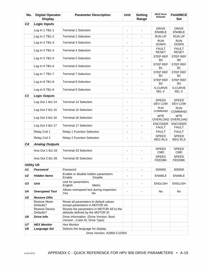
No. Digital OperatorDisplay
Parameter Description Unit SettingRange
MCE DriveDefaults
Field/MCESet
42-02-2P22 APPENDIX C - QUICK REFERENCE FOR HPV 900 DRIVE PARAMETERS • A-19
C2 Logic Inputs
Log In 1 TB1-1 Terminal 1 Selection - - DRIVEENABLE
DRIVEENABLE
Log In 2 TB1-2 Terminal 2 Selection - - RUN UP RUN UP
Log In 3 TB1-3 Terminal 3 Selection - - RUNDOWN
RUNDOWN
Log In 4 TB1-4 Terminal 4 Selection - - FAULTRESET
FAULTRESET
Log In 5 TB1-5 Terminal 5 Selection - - STEP REFB0
STEP REFB0
Log In 6 TB1-6 Terminal 6 Selection - - STEP REFB1
STEP REFB1
Log In 7 TB1-7 Terminal 7 Selection - - STEP REFB2
STEP REFB2
Log In 8 TB1-8 Terminal 8 Selection - - STEP REFB3
STEP REFB3
Log In 9 TB1-9 Terminal 9 Selection - - S-CURVESEL 0
S-CURVESEL 0
C3 Logic Outputs
Log Out 1 tb1-14 Terminal 14 Selection - - SPEEDDEV LOW
SPEEDDEV LOW
Log Out 2 tb1-15 Terminal 15 Selection - -RUN
COMMANDRUN
COMMAND
Log Out 3 tb1-16 Terminal 16 Selection - - MTROVERLOAD
MTROVERLOAD
Log Out 4 tb1-17 Terminal 17 Selection - - ENCODERFAULT
ENCODERFAULT
Relay Coil 1 Relay 1 Function Selection - - FAULT FAULT
Relay Coil 2 Relay 2 Function Selection - - SPEEDREG RLS
SPEEDREG RLS
C4 Analog Outputs
Ana Out 1 tb1-33 Terminal 33 Selection - - SPEEDCMD
SPEEDCMD
Ana Out 2 tb1-35 Terminal 35 Selection - - SPEEDFEEDBK
SPEEDFEEDBK
Utility U0U1 Password Password - - 000000 000000
U2 Hidden Items Enable or disable hidden parametersEnable Disable - - ENABLE ENABLE
U3 Unit Unit for parametersEnglish Metric - - ENGLISH ENGLISH
U4 Overspeed Test Allows overspeed test during inspectionYes No - - No No
U5 Restore DfltsRestore MotorDefaults?
Reset all parameters to default valuesexcept parameters in MOTOR A5
Restore DeviceDefaults?
Resets the parameters in MOTOR A5 to thedefaults defined by the MOTOR ID
U6 Drive Info Drive information (Drive Version, BootVersion , Cube ID, Drive Type)
U7 HEX Monitor Hex MonitorU8 Language Sel Selects the language for display
Drive Version: A2950-C10304
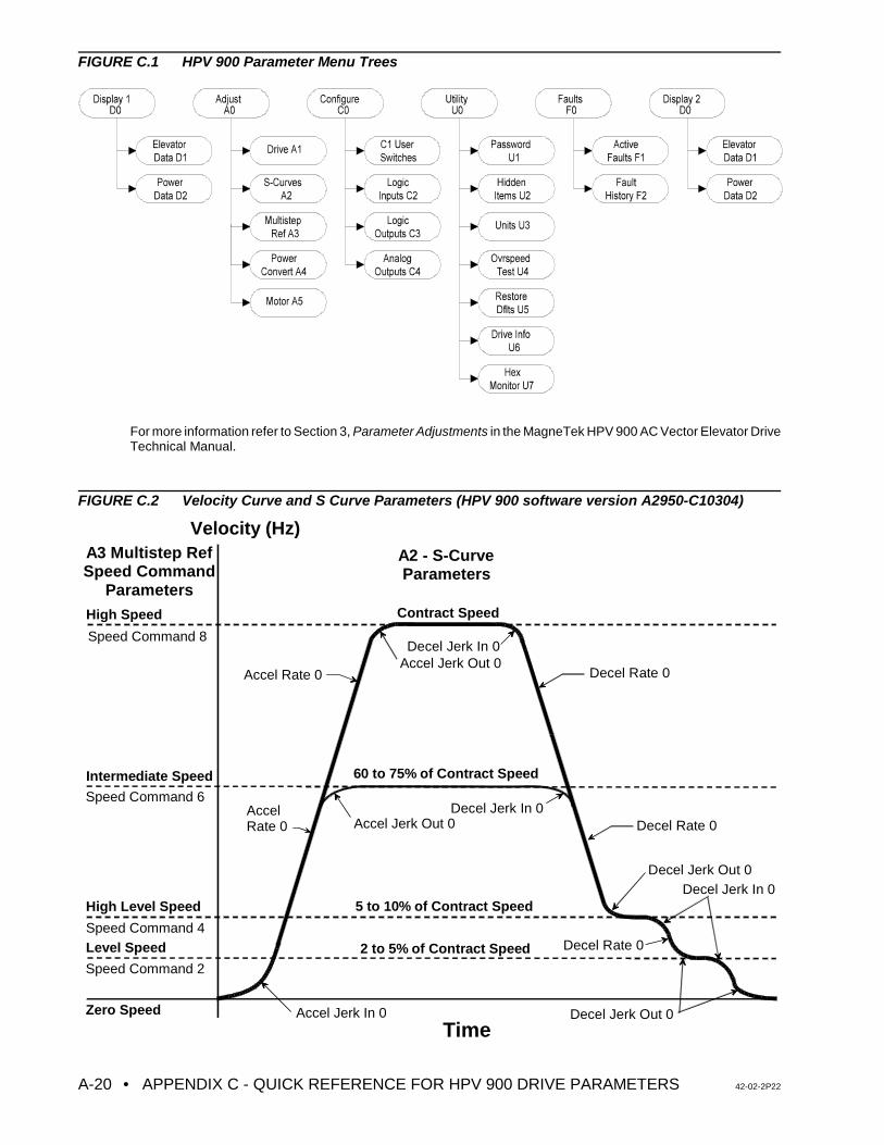
• APPENDIX C - QUICK REFERENCE FOR HPV 900 DRIVE PARAMETERS 42-02-2P22A-20
Velocity (Hz)
TimeZero Speed
Level Speed
High Level Speed
Intermediate Speed
High Speed
Accel Jerk In 0
Accel Rate 0 Decel Rate 0
Decel Jerk Out 0
Accel Jerk Out 0
Decel Jerk In 0
Decel Jerk In 0
Decel Jerk In 0
Contract Speed
5 to 10% of Contract Speed
2 to 5% of Contract Speed
A3 Multistep RefSpeed Command
Parameters
A2 - S-CurveParameters
Decel Rate 0
Decel Rate 0Accel Rate 0
60 to 75% of Contract Speed
Speed Command 8
Speed Command 6
Speed Command 4
Speed Command 2
Accel Jerk Out 0
Decel Jerk Out 0
FIGURE C.1 HPV 900 Parameter Menu Trees
For more information refer to Section 3, Parameter Adjustments in the MagneTek HPV 900 AC Vector Elevator DriveTechnical Manual.
FIGURE C.2 Velocity Curve and S Curve Parameters (HPV 900 software version A2950-C10304)
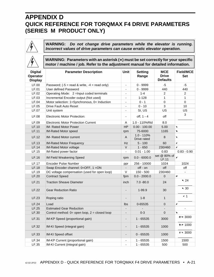
42-02-2P22 APPENDIX D - QUICK REFERENCE FOR TORQMAX F4 DRIVE PARAMETERS • A-21
WARNING: Do not change drive parameters while the elevator is running.Incorrect values of drive parameters can cause erratic elevator operation.
WARNING: Parameters with an asterisk (u) must be set correctly for your specificmotor / machine / job. Refer to the adjustment manual for detailed information.
APPENDIX DQUICK REFERENCE FOR TORQMAX F4 DRIVE PARAMETERS(SERIES M PRODUCT ONLY)
DigitalOperator Display
Parameter Description Unit SettingRange
MCEDrive
Defaults
Field/MCESet
LF.00 Password; (-5 = read & write, -4 = read only) - 0 - 9999 -5 -5LF.01 User defined Password - 0 - 9999 440 440LF.02 Operating Mode: 2 =Input coded terminals - 1-4 2 2LF.03 Incremental Encoder output (Not used) - 1-128 1 1LF.04 Motor selection: 1=Synchronous, 0= Induction - 0 - 1 0 0LF.05 Drive Fault Auto Reset - 0 - 10 3 10LF.07 Unit system - SI, US US US
LF.08 Electronic Motor Protection: - off, 1 - 4 off 3________
LF.09 Electronic Motor Protection Current A 1.0 - 110%Rtd 8.0LF.10 IM- Rated Motor Power HP 0.00 - 100.00 5.00 u LF.11 IM-Rated Motor speed rpm 75-6000 1165 u
LF.12 IM- Rated Motor current A 1.0 - 110%Drive rated 8 u
LF.13 IM-Rated Motor Frequency Hz 5 - 100 60 u
LF.14 IM-Rated Motor voltage V 1 - 650 230/460 u
LF.15 IM-Rated power factor - 0.01 - 1.00 0.83 0.83 - 0.90
LF.16 IM Field Weakening Speed rpm 0.0 - 6000.0 set @ 80% ofLF.11 u
LF.17 Encoder Pulse Number ppr 256 - 10000 1024 1024LF.18 Swap Encoder channel: 0=OFF, 1 =ON - off - on off offLF.19 DC voltage compensation (used for open loop) V 150 - 500 230/460 -LF.20 Contract Speed fpm 0.0 - 2000.0 0 u
LF.21 Traction Sheave Diameter inch 7.0 -80.0 24 u 24________
LF.22 Gear Reduction Ratio - 1-99.9 30 u 30________
LF.23 Roping ratio - 1-8 1 u 1________
LF.24 Load lbs 0-65535 0 u
LF.25 Estimated Gear Reduction - - - -LF.30 Control method: 0= open loop, 2 = closed loop - 0-3 0 u
LF.31 IM-KP Speed (proportional gain) - 1 - 65535 3000 uu 3000________
LF.32 IM-KI Speed (integral gain) - 1 - 65535 1000 uu 1000________
LF.33 IM-KI Speed offset - 0 - 65535 1000 uu 3000________
LF.34 IM-KP Current (proportional gain) - 1 - 65535 1500 1500LF.35 IM-KI Current (integral gain) - 1 - 65535 500 500
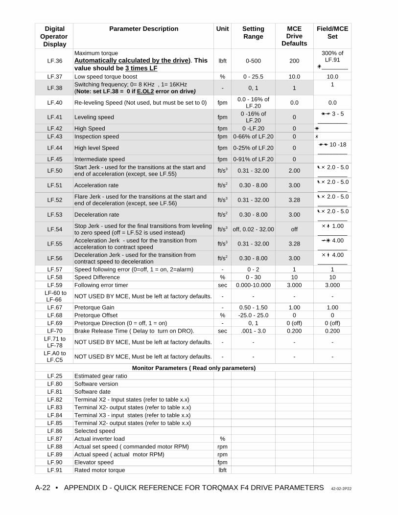
DigitalOperator Display
Parameter Description Unit SettingRange
MCEDrive
Defaults
Field/MCESet
• APPENDIX D - QUICK REFERENCE FOR TORQMAX F4 DRIVE PARAMETERS 42-02-2P22A-22
LF.36Maximum torqueAutomatically calculated by the drive). Thisvalue should be 3 times LF
lbft 0-500 200300% of
LF.91u________
LF.37 Low speed torque boost % 0 - 25.5 10.0 10.0
LF.38Switching frequency; 0= 8 KHz , 1= 16KHz (Note: set LF.38 = 0 if E.OL2 error on drive) - 0, 1 1
1
LF.40 Re-leveling Speed (Not used, but must be set to 0) fpm 0.0 - 16% ofLF.20 0.0 0.0
LF.41 Leveling speed fpm 0 -16% ofLF.20 0 uu 3 - 5
_________LF.42 High Speed fpm 0 -LF.20 0 u
LF.43 Inspection speed fpm 0-66% of LF.20 0 u
LF.44 High level Speed fpm 0-25% of LF.20 0 uu 10 -18_________
LF.45 Intermediate speed fpm 0-91% of LF.20 0
LF.50 Start Jerk - used for the transitions at the start andend of acceleration (except, see LF.55) ft/s3 0.31 - 32.00 2.00 uu 2.0 - 5.0
_________
LF.51 Acceleration rate ft/s2 0.30 - 8.00 3.00 uu 2.0 - 5.0_________
LF.52 Flare Jerk - used for the transitions at the start andend of deceleration (except, see LF.56) ft/s3 0.31 - 32.00 3.28 uu 2.0 - 5.0
_________
LF.53 Deceleration rate ft/s2 0.30 - 8.00 3.00 uu 2.0 - 5.0_________
LF.54 Stop Jerk - used for the final transitions from levelingto zero speed (off = LF.52 is used instead) ft/s3 off, 0.02 - 32.00 off uu 1.00
_________
LF.55 Acceleration Jerk - used for the transition fromacceleration to contract speed ft/s3 0.31 - 32.00 3.28 uu 4.00
_________
LF.56 Deceleration Jerk - used for the transition fromcontract speed to deceleration ft/s2 0.30 - 8.00 3.00 uu 4.00
_________LF.57 Speed following error (0=off, 1 = on, 2=alarm) - 0 - 2 1 1LF.58 Speed Difference % 0 - 30 10 10LF.59 Following error timer sec 0.000-10.000 3.000 3.000
LF-60 to LF-66 NOT USED BY MCE, Must be left at factory defaults. - - - -
LF.67 Pretorque Gain - 0.50 - 1.50 1.00 1.00LF.68 Pretorque Offset % -25.0 - 25.0 0 0LF.69 Pretorque Direction (0 = off, 1 = on) - 0, 1 0 (off) 0 (off)LF-70 Brake Release Time ( Delay to turn on DRO). sec .001 - 3.0 0.200 0.200
LF.71 to LF-78 NOT USED BY MCE, Must be left at factory defaults. - - - -
LF.A0 toLF.C5 NOT USED BY MCE, Must be left at factory defaults. - - - -
Monitor Parameters ( Read only parameters)LF.25 Estimated gear ratioLF.80 Software versionLF.81 Software dateLF.82 Terminal X2 - Input states (refer to table x.x)LF.83 Terminal X2- output states (refer to table x.x)LF.84 Terminal X3 - input states (refer to table x.x)LF.85 Terminal X2- output states (refer to table x.x)LF.86 Selected speedLF.87 Actual inverter load %LF.88 Actual set speed ( commanded motor RPM) rpmLF.89 Actual speed ( actual motor RPM) rpmLF.90 Elevator speed fpmLF.91 Rated motor torque lbft
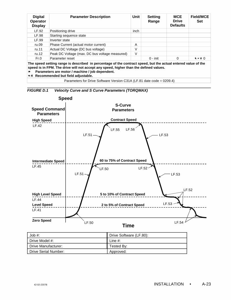
DigitalOperator Display
Parameter Description Unit SettingRange
MCEDrive
Defaults
Field/MCESet
42-02-2207B INSTALLATION • A-23
Speed
TimeZero Speed
Level Speed
High Level Speed
Intermediate Speed
High Speed
LF.50
LF.51 LF.53
LF.54
LF.50
LF.55
LF.52
LF.52
Contract Speed
5 to 10% of Contract Speed
2 to 5% of Contract Speed
Speed CommandParameters
S-CurveParameters
LF.53
LF.53LF.51
60 to 75% of Contract Speed
LF.42
LF.45
LF.44
LF.41
LF.56
LF.92 Positioning drive inchLF.98 Starting sequence stateLF.99 Inverter stateru.09 Phase Current (actual motor current) Aru.11 Actual DC Voltage (DC bus voltage) Vru.12 Peak DC Voltage (max. DC bus voltage measured) VFr.0 Parameter reset 0 - init 0 uuu 0
The speed setting range is described in percentage of the contract speed, but the actual entered value of thespeed is in FPM. The drive will not accept any speed, higher than the defined values. u Parameters are motor / machine / job dependent.uu Recommended but field adjustable.
Parameters for Drive Software Version C31A (LF.81 date code = 0209.4)
FIGURE D.1 Velocity Curve and S Curve Parameters (TORQMAX)
Job #: Drive Software (LF.80):Drive Model #: Line #:Drive Manufacturer: Tested By:Drive Serial Number: Approved:
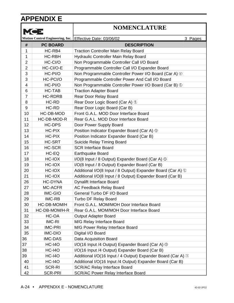
• APPENDIX E - NOMENCLATURE 42-02-2P22A-24
APPENDIX ENOMENCLATURE
Motion Control Engineering, Inc. Effective Date: 03/06/02 3 Pages
# PC BOARD DESCRIPTION 1 HC-RB4 Traction Controller Main Relay Board1 HC-RBH Hydraulic Controller Main Relay Board2 HC-CI/O Non Programmable Controller Call I/O Board2 HC-CI/O-E Programmable Controller Call I/O Expander Board3 HC-PI/O Non Programmable Controller Power I/O Board (Car A) â3 HC-PCI/O Programmable Controller Power And Call I/O Board4 HC-PI/O Non Programmable Controller Power I/O Board (Car B) â6 HC-TAB Traction Adapter Board7 HC-RDRB Rear Door Relay Board8 HC-RD Rear Door Logic Board (Car A) â9 HC-RD Rear Door Logic Board (Car B)
10 HC-DB-MOD Front G.A.L. MOD Door Interface Board11 HC-DB-MOD-R Rear G.A.L. MOD Door Interface Board12 HC-DPS Door Power Supply Board13 HC-PIX Position Indicator Expander Board (Car A) â14 HC-PIX Position Indicator Expander Board (Car B)15 HC-SRT Suicide Relay Timing Board16 HC-SCR SCR Interface Board17 HC-EQ Earthquake Board18 HC-IOX I/O(8 Input / 8 Output) Expander Board (Car A) â19 HC-IOX I/O(8 Input / 8 Output) Expander Board (Car B)20 HC-IOX Additional I/O(8 Input / 8 Output) Expander Board (Car A) â21 HC-IOX Additional I/O(8 Input / 8 Output) Expander Board (Car B)26 HC-DYNA Dynalift Interface Board27 MC-ACFR AC Feedback Relay Board28 IMC-GIO General Turbo DF I/O Board29 IMC-RB Turbo DF Relay Board30 HC-DB-MOM/H Front G.A.L. MOM/MOH Door Interface Board31 HC-DB-MOM/H-R Rear G.A.L. MOM/MOH Door Interface Board32 HC-OA Output Adapter Board33 IMC-RI M/G Relay Interface Board34 IMC-PRI M/G Power Relay Interface Board35 IMC-DIO Digital I/O Board
36 IMC-DAS Data Acquisition Board37 HC-I4O I/O(16 Input /4 Output) Expander Board (Car A) â38 HC-I4O I/O(16 Input /4 Output) Expander Board (Car B)39 HC-I4O Additional I/O(16 Input / 4 Output) Expander Board (Car A) â40 HC-I4O Additional I/O(16 Input /4 Output) Expander Board (Car B)41 SCR-RI SCR/AC Relay Interface Board42 SCR-PRI SCR/AC Power Relay Interface Board
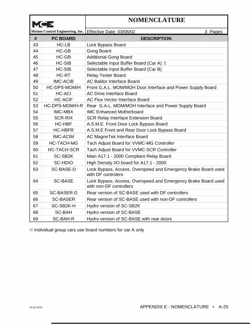
NOMENCLATURE
Motion Control Engineering, Inc. Effective Date: 03/06/02 3 Pages
# PC BOARD DESCRIPTION
42-02-2P22 APPENDIX E - NOMENCLATURE • A-25
43 HC-LB Lock Bypass Board44 HC-GB Gong Board45 HC-GB Additional Gong Board46 HC-SIB Selectable Input Buffer Board (Car A) â47 HC-SIB Selectable Input Buffer Board (Car B)48 HC-RT Relay Tester Board49 IMC-ACIB AC Baldor Interface Board50 HC-DPS-MOM/H Front G.A.L. MOM/MOH Door Interface and Power Supply Board51 HC-ACI AC Drive Interface Board52 HC-ACIF AC Flux Vector Interface Board53 HC-DPS-MOM/H-R Rear G.A.L. MOM/MOH Interface and Power Supply Board54 IMC-MBX IMC Enhanced Motherboard55 SCR-RIX SCR Relay Interface Extension Board56 HC-HBF A.S.M.E. Front Door Lock Bypass Board57 HC-HBFR A.S.M.E Front and Rear Door Lock Bypass Board
58 IMC-ACIM AC MagneTek Interface Board
59 HC-TACH-MG Tach Adjust Board for VVMC-MG Controller
60 HC-TACH-SCR Tach Adjust Board for VVMC-SCR Controller
61 SC-SB2K Main A17.1 - 2000 Compliant Relay Board
62 SC-HDIO High Density I/O board for A17.1 - 2000
63 SC-BASE-D Lock Bypass, Access, Overspeed and Emergency Brake Board usedwith DF controlers
64 SC-BASE Lock Bypass, Access, Overspeed and Emergency Brake Board usedwith non-DF controllers
65 SC-BASER-D Rear version of SC-BASE used with DF controllers
66 SC-BASER Rear version of SC-BASE used with non-DF controllers
67 SC-SB2K-H Hydro version of SC-SB2K
68 SC-BAH Hydro version of SC-BASE
69 SC-BAH-R Hydro version of SC-BASE with rear doors
â Individual group cars use board numbers for car A only
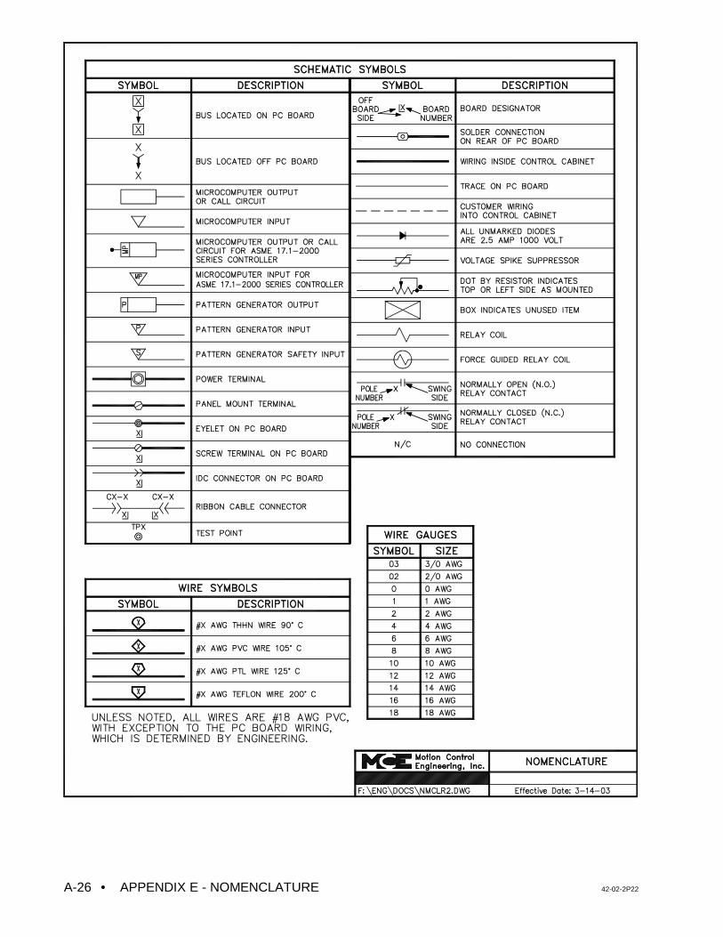
• APPENDIX E - NOMENCLATURE 42-02-2P22A-26
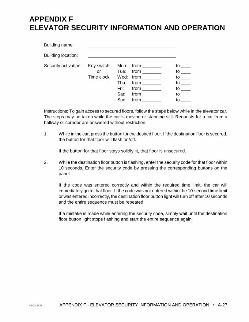
42-02-2P22 APPENDIX F - ELEVATOR SECURITY INFORMATION AND OPERATION • A-27
APPENDIX FELEVATOR SECURITY INFORMATION AND OPERATION
Building name:
Building location:
Security activation: Key switch Mon: from to or Tue: from to Time clock Wed: from to
Thu: from to Fri: from to Sat: from to Sun: from to
Instructions: To gain access to secured floors, follow the steps below while in the elevator car.The steps may be taken while the car is moving or standing still. Requests for a car from ahallway or corridor are answered without restriction.
1. While in the car, press the button for the desired floor. If the destination floor is secured,the button for that floor will flash on/off.
If the button for that floor stays solidly lit, that floor is unsecured.
2. While the destination floor button is flashing, enter the security code for that floor within10 seconds. Enter the security code by pressing the corresponding buttons on thepanel.
If the code was entered correctly and within the required time limit, the car willimmediately go to that floor. If the code was not entered within the 10-second time limitor was entered incorrectly, the destination floor button light will turn off after 10 secondsand the entire sequence must be repeated.
If a mistake is made while entering the security code, simply wait until the destinationfloor button light stops flashing and start the entire sequence again.
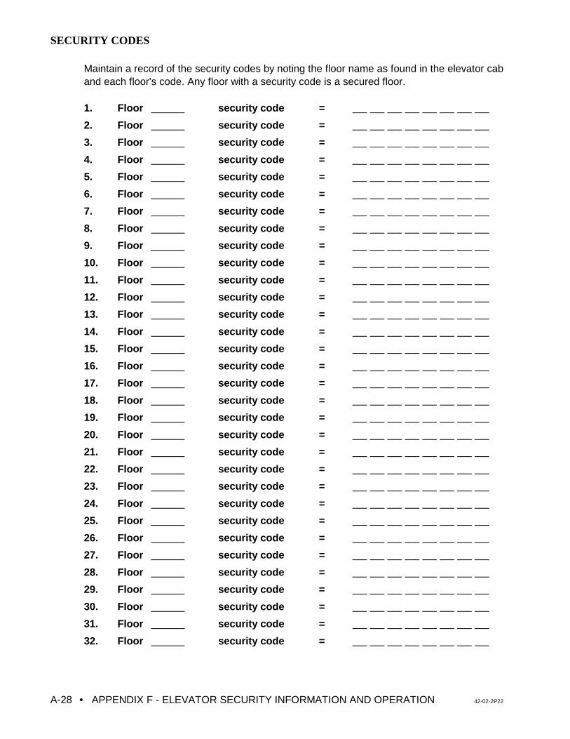
• APPENDIX F - ELEVATOR SECURITY INFORMATION AND OPERATION 42-02-2P22A-28
SECURITY CODES
Maintain a record of the security codes by noting the floor name as found in the elevator caband each floor's code. Any floor with a security code is a secured floor.
1. Floor security code =
2. Floor security code =
3. Floor security code =
4. Floor security code =
5. Floor security code =
6. Floor security code =
7. Floor security code =
8. Floor security code =
9. Floor security code =
10. Floor security code =
11. Floor security code =
12. Floor security code =
13. Floor security code =
14. Floor security code =
15. Floor security code =
16. Floor security code =
17. Floor security code =
18. Floor security code =
19. Floor security code =
20. Floor security code =
21. Floor security code =
22. Floor security code =
23. Floor security code =
24. Floor security code =
25. Floor security code =
26. Floor security code =
27. Floor security code =
28. Floor security code =
29. Floor security code =
30. Floor security code =
31. Floor security code =
32. Floor security code =
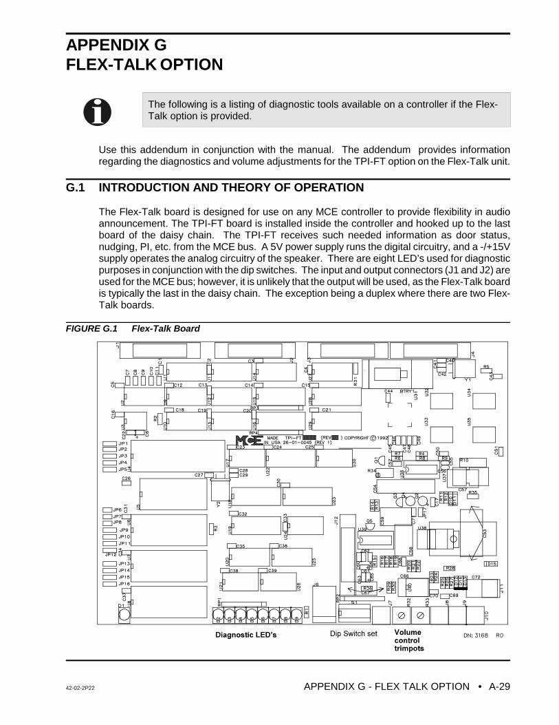
42-02-2P22 APPENDIX G - FLEX TALK OPTION • A-29
The following is a listing of diagnostic tools available on a controller if the Flex-Talk option is provided.
APPENDIX G FLEX-TALK OPTION
Use this addendum in conjunction with the manual. The addendum provides informationregarding the diagnostics and volume adjustments for the TPI-FT option on the Flex-Talk unit.
G.1 INTRODUCTION AND THEORY OF OPERATION
The Flex-Talk board is designed for use on any MCE controller to provide flexibility in audioannouncement. The TPI-FT board is installed inside the controller and hooked up to the lastboard of the daisy chain. The TPI-FT receives such needed information as door status,nudging, PI, etc. from the MCE bus. A 5V power supply runs the digital circuitry, and a -/+15Vsupply operates the analog circuitry of the speaker. There are eight LED’s used for diagnosticpurposes in conjunction with the dip switches. The input and output connectors (J1 and J2) areused for the MCE bus; however, it is unlikely that the output will be used, as the Flex-Talk boardis typically the last in the daisy chain. The exception being a duplex where there are two Flex-Talk boards.
FIGURE G.1 Flex-Talk Board
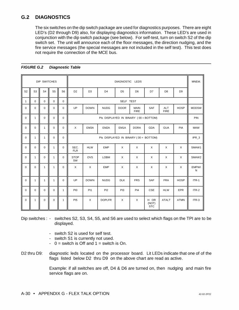
• APPENDIX G - FLEX TALK OPTION 42-02-2P22A-30
G.2 DIAGNOSTICS
The six switches on the dip switch package are used for diagnostics purposes. There are eightLED’s (D2 through D9) also, for displaying diagnostics information. These LED’s are used inconjunction with the dip switch package (see below). For self-test, turn on switch S2 of the dipswitch set. The unit will announce each of the floor messages, the direction nudging, and thefire service messages (the special messages are not included in the self test). This test doesnot require the connection of the MCE bus.
FIGURE G.2 Diagnostic Table
DIP SWITCHES DIAGNOSTIC LEDS MNEM.
S2 S3 S4 S5 S6 D2 D3 D4 D5 D6 D7 D8 D9
1 0 0 0 0 SELF TEST
0 0 0 0 0 UP DOWN NUDG DOOR MAINFIRE
SAF ALTFIRE
HOSP MODSW
0 1 0 0 0 PIs DISPLAYED IN BINARY ( 00 = BOTTOM) PIN
0 0 1 0 0 X EM3A EM2A EM1A DORA GDA GUA PIA MAW
0 1 1 0 0 PIs DISPLAYED IN BINARY ( 00 = BOTTOM) IPR_3
0 0 0 1 0 SEC.FLR
HLW EMP X X X X X SMAW1
0 1 0 1 0 STOPSW
OVS LOBM X X X X X SMAW2
0 0 1 1 0 X X EMP X X X X X EMPWIN
0 1 1 1 0 UP DOWN NUDG DLK FRS SAF FRA HOSP ITR-1
0 0 0 0 1 PI0 PI1 PI2 PI3 PI4 CSE HLW EPR ITR-2
0 1 0 0 1 PI5 X DOPLFR X X H OR(NOT)STC
ATALT ATMN ITR-3
Dip switches : - switches S2, S3, S4, S5, and S6 are used to select which flags on the TPI are to bedisplayed.
- switch S2 is used for self test.- switch S1 is currently not used.- 0 = switch is Off and 1 = switch is On.
D2 thru D9: diagnostic leds located on the processor board. Lit LEDs indicate that one of of theflags listed below D2 thru D9 on the above chart are read as active.
Example: if all switches are off, D4 & D6 are turned on, then nudging and main fireservice flags are on.
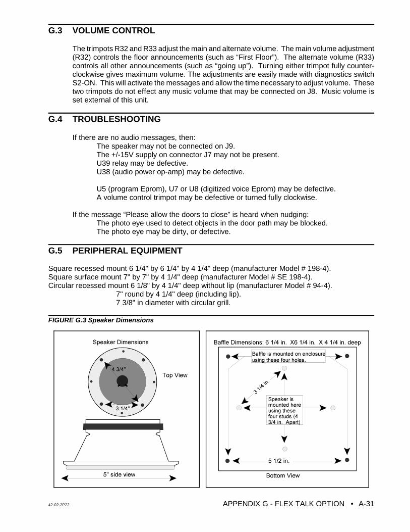
42-02-2P22 APPENDIX G - FLEX TALK OPTION • A-31
G.3 VOLUME CONTROL
The trimpots R32 and R33 adjust the main and alternate volume. The main volume adjustment(R32) controls the floor announcements (such as “First Floor”). The alternate volume (R33)controls all other announcements (such as “going up”). Turning either trimpot fully counter-clockwise gives maximum volume. The adjustments are easily made with diagnostics switchS2-ON. This will activate the messages and allow the time necessary to adjust volume. Thesetwo trimpots do not effect any music volume that may be connected on J8. Music volume isset external of this unit.
G.4 TROUBLESHOOTING
If there are no audio messages, then:The speaker may not be connected on J9.The +/-15V supply on connector J7 may not be present.U39 relay may be defective.
U38 (audio power op-amp) may be defective.
U5 (program Eprom), U7 or U8 (digitized voice Eprom) may be defective.A volume control trimpot may be defective or turned fully clockwise.
If the message “Please allow the doors to close” is heard when nudging:The photo eye used to detect objects in the door path may be blocked.The photo eye may be dirty, or defective.
G.5 PERIPHERAL EQUIPMENT
Square recessed mount 6 1/4" by 6 1/4" by 4 1/4" deep (manufacturer Model # 198-4).Square surface mount 7" by 7" by 4 1/4" deep (manufacturer Model # SE 198-4).Circular recessed mount 6 1/8" by 4 1/4" deep without lip (manufacturer Model # 94-4).
7" round by 4 1/4" deep (including lip). 7 3/8" in diameter with circular grill.
FIGURE G.3 Speaker Dimensions
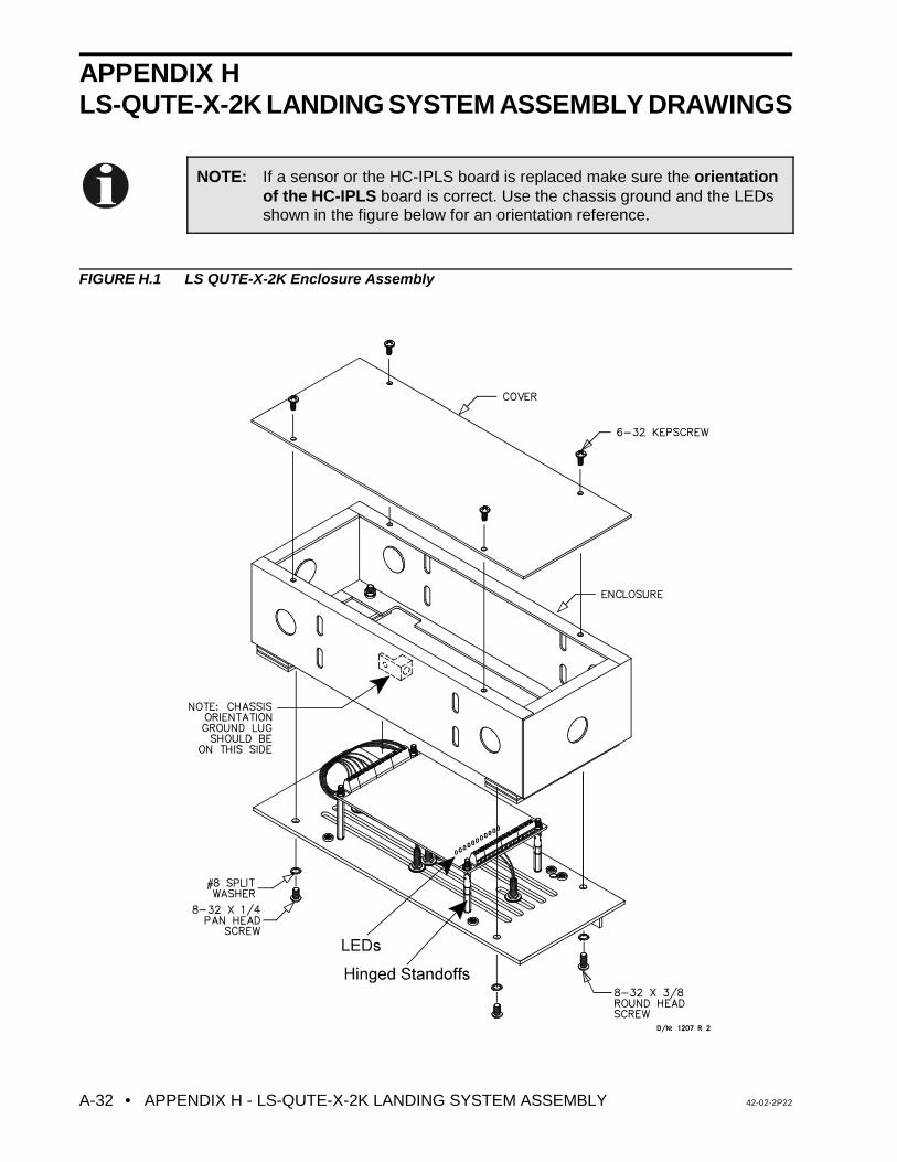
• APPENDIX H - LS-QUTE-X-2K LANDING SYSTEM ASSEMBLY 42-02-2P22A-32
APPENDIX HLS-QUTE-X-2K LANDING SYSTEM ASSEMBLY DRAWINGS
FIGURE H.1 LS QUTE-X-2K Enclosure Assembly
NOTE: If a sensor or the HC-IPLS board is replaced make sure the orientationof the HC-IPLS board is correct. Use the chassis ground and the LEDsshown in the figure below for an orientation reference.
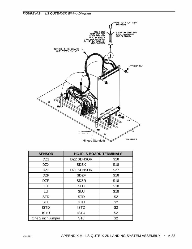
42-02-2P22 APPENDIX H - LS-QUTE-X-2K LANDING SYSTEM ASSEMBLY • A-33
FIGURE H.2 LS QUTE-X-2K Wiring Diagram
SENSOR HC-IPLS BOARD TERMINALS
DZ1 DZ2 SENSOR S18
DZX SDZX S18
DZ2 DZ1 SENSOR S27
DZF SDZF S18
DZR SDZR S18
LD SLD S18
LU SLU S18
STD STD S2
STU STU S2
ISTD ISTD S2
ISTU ISTU S2
One 2 inch jumper S18 S2
• APPENDIX I - POWERBACK R4 REGENERATIVE DRIVE 42-02-2P22A-34
APPENDIX IQUICK REFERENCE FOR POWERBACK R4 REGENERATIVE AC DRIVE PARAMETERS (SERIES M and IMC-AC-R)
I.1 GENERAL
The following information pertains to VVMC-1000-PTC Series M controllers with the additionof the POWERBACK R4 Regenerative Drive.
I.2 REGENERATIVE DRIVE INTERFACE
The following is an explanation of the POWERBACK R4 Regenerative Drive interface.
I.2.1 DRIVE INPUTS
• Drive Enable (Terminal 8): This input enables the R4 drive and puts the drive instandby mode. Drive parameter ru. 0 reads stby during motoring condition and Activeduring deceleration/overhauling conditions. A voltage between drive terminals 7 & 8 of18 VDC = ON, 0 VAC = OFF.
• Drive Reset (Terminal 11): This input resets an R4 drive fault. Pressing the drive resetbutton on the HC-ACI board activates the reset input and clears regenerative drivefaults. A voltage between drive terminal 11 & 7 of 18 VDC = ON, 0 VAC = OFF.
I.2.2 DRIVE OUTPUT
• Drive ready contact: The contacts between terminals 1 and 3 on the R4 drive remainclosed under normal condition and open during a fault, which drops the RDY relay onthe HC-ACI board. Pressing the Drive Reset button on the HC-ACI board should clearthe R4 drive fault and should turn ON the RDY relay.
I.2.3 POWER CONNECTIONS
a. It is recommended that the L1, L2, L3 connections on the Inverter and the R4 drive bein phase.
b. The input power connections ( L1-2, L2-2, L3-2 ) and the phase monitoring connections( L1, L2, L3) on the R4 drive must be in phase. If these connections are not in phasethe R4 drive will trip fault E.Syn and drop the RDY relay on the HC-ACI board. If the R4drive trips on E.nEt at power up or trips the over voltage E.oP fault at the end of a run,one of the phase monitoring fuses may be open or there may be a loose connection onthe phase monitor inputs.
c. The DC bus connections must be correct and according to the drawings. It is critical
that DC bus connections be correct. Incorrect connections will damage the driveunits.
d. The line inductor ground connection to the R4 Drive and F4 Drive must be completedaccording to the drawings.
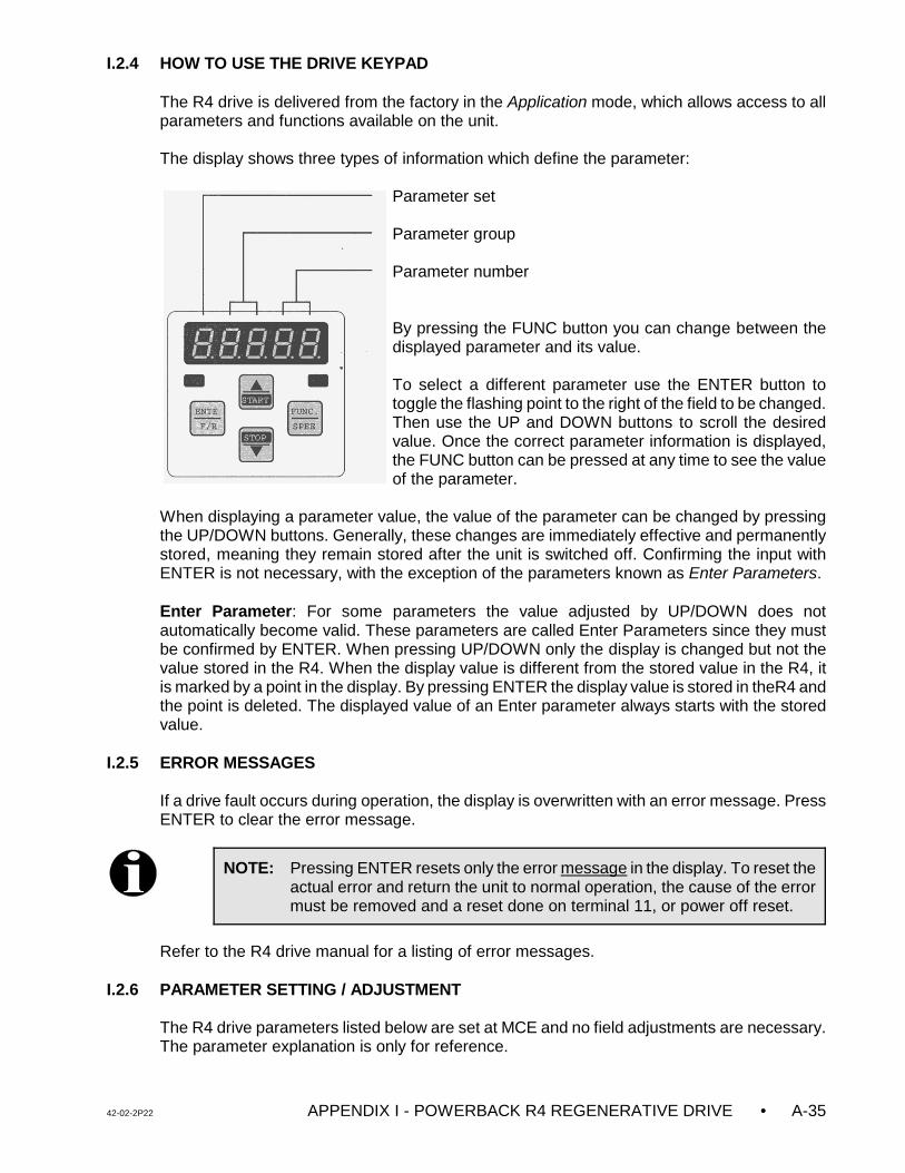
42-02-2P22 APPENDIX I - POWERBACK R4 REGENERATIVE DRIVE • A-35
NOTE: Pressing ENTER resets only the error message in the display. To reset theactual error and return the unit to normal operation, the cause of the errormust be removed and a reset done on terminal 11, or power off reset.
I.2.4 HOW TO USE THE DRIVE KEYPAD
The R4 drive is delivered from the factory in the Application mode, which allows access to allparameters and functions available on the unit.
The display shows three types of information which define the parameter:
Parameter set
Parameter group
Parameter number
By pressing the FUNC button you can change between thedisplayed parameter and its value.
To select a different parameter use the ENTER button totoggle the flashing point to the right of the field to be changed.Then use the UP and DOWN buttons to scroll the desiredvalue. Once the correct parameter information is displayed,the FUNC button can be pressed at any time to see the valueof the parameter.
When displaying a parameter value, the value of the parameter can be changed by pressingthe UP/DOWN buttons. Generally, these changes are immediately effective and permanentlystored, meaning they remain stored after the unit is switched off. Confirming the input withENTER is not necessary, with the exception of the parameters known as Enter Parameters.
Enter Parameter: For some parameters the value adjusted by UP/DOWN does notautomatically become valid. These parameters are called Enter Parameters since they mustbe confirmed by ENTER. When pressing UP/DOWN only the display is changed but not thevalue stored in the R4. When the display value is different from the stored value in the R4, itis marked by a point in the display. By pressing ENTER the display value is stored in theR4 andthe point is deleted. The displayed value of an Enter parameter always starts with the storedvalue.
I.2.5 ERROR MESSAGES
If a drive fault occurs during operation, the display is overwritten with an error message. PressENTER to clear the error message.
Refer to the R4 drive manual for a listing of error messages.
I.2.6 PARAMETER SETTING / ADJUSTMENT
The R4 drive parameters listed below are set at MCE and no field adjustments are necessary.The parameter explanation is only for reference.
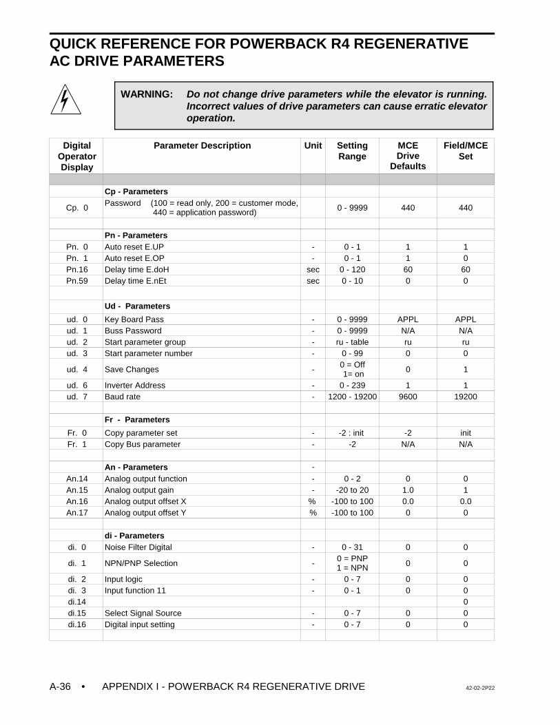
• APPENDIX I - POWERBACK R4 REGENERATIVE DRIVE 42-02-2P22A-36
WARNING: Do not change drive parameters while the elevator is running.Incorrect values of drive parameters can cause erratic elevatoroperation.
QUICK REFERENCE FOR POWERBACK R4 REGENERATIVE AC DRIVE PARAMETERS
DigitalOperatorDisplay
Parameter Description Unit SettingRange
MCEDrive
Defaults
Field/MCESet
Cp - Parameters
Cp. 0 Password (100 = read only, 200 = customer mode, 440 = application password) 0 - 9999 440 440
Pn - ParametersPn. 0 Auto reset E.UP - 0 - 1 1 1Pn. 1 Auto reset E.OP - 0 - 1 1 0Pn.16 Delay time E.doH sec 0 - 120 60 60Pn.59 Delay time E.nEt sec 0 - 10 0 0
Ud - Parameters
ud. 0 Key Board Pass - 0 - 9999 APPL APPLud. 1 Buss Password - 0 - 9999 N/A N/Aud. 2 Start parameter group - ru - table ru ruud. 3 Start parameter number - 0 - 99 0 0
ud. 4 Save Changes - 0 = Off 1= on 0 1
ud. 6 Inverter Address - 0 - 239 1 1ud. 7 Baud rate - 1200 - 19200 9600 19200
Fr - Parameters
Fr. 0 Copy parameter set - -2 : init -2 initFr. 1 Copy Bus parameter - -2 N/A N/A
An - Parameters -An.14 Analog output function - 0 - 2 0 0An.15 Analog output gain - -20 to 20 1.0 1An.16 Analog output offset X % -100 to 100 0.0 0.0An.17 Analog output offset Y % -100 to 100 0 0
di - Parametersdi. 0 Noise Filter Digital - 0 - 31 0 0
di. 1 NPN/PNP Selection - 0 = PNP1 = NPN 0 0
di. 2 Input logic - 0 - 7 0 0di. 3 Input function 11 - 0 - 1 0 0di.14 0di.15 Select Signal Source - 0 - 7 0 0di.16 Digital input setting - 0 - 7 0 0
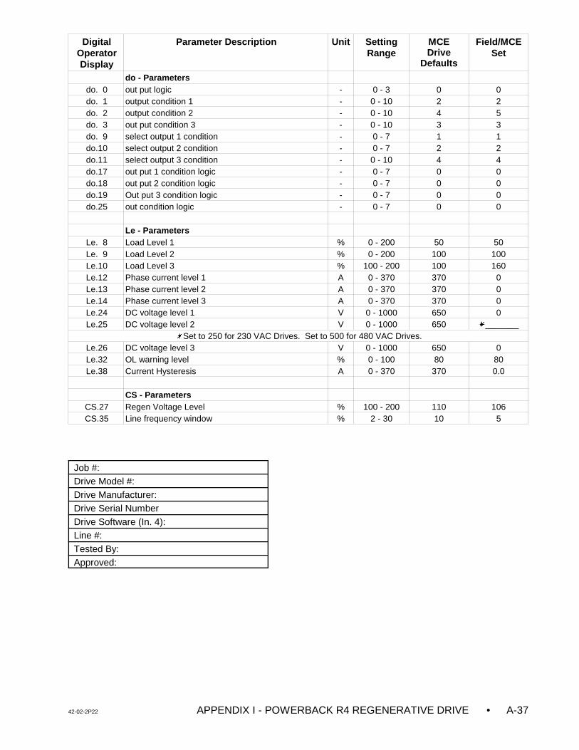
DigitalOperatorDisplay
Parameter Description Unit SettingRange
MCEDrive
Defaults
Field/MCESet
42-02-2P22 APPENDIX I - POWERBACK R4 REGENERATIVE DRIVE • A-37
do - Parametersdo. 0 out put logic - 0 - 3 0 0do. 1 output condition 1 - 0 - 10 2 2do. 2 output condition 2 - 0 - 10 4 5do. 3 out put condition 3 - 0 - 10 3 3do. 9 select output 1 condition - 0 - 7 1 1do.10 select output 2 condition - 0 - 7 2 2do.11 select output 3 condition - 0 - 10 4 4do.17 out put 1 condition logic - 0 - 7 0 0do.18 out put 2 condition logic - 0 - 7 0 0do.19 Out put 3 condition logic - 0 - 7 0 0do.25 out condition logic - 0 - 7 0 0
Le - ParametersLe. 8 Load Level 1 % 0 - 200 50 50Le. 9 Load Level 2 % 0 - 200 100 100Le.10 Load Level 3 % 100 - 200 100 160Le.12 Phase current level 1 A 0 - 370 370 0Le.13 Phase current level 2 A 0 - 370 370 0Le.14 Phase current level 3 A 0 - 370 370 0Le.24 DC voltage level 1 V 0 - 1000 650 0Le.25 DC voltage level 2 V 0 - 1000 650 u_______
uSet to 250 for 230 VAC Drives. Set to 500 for 480 VAC Drives.Le.26 DC voltage level 3 V 0 - 1000 650 0Le.32 OL warning level % 0 - 100 80 80Le.38 Current Hysteresis A 0 - 370 370 0.0
CS - ParametersCS.27 Regen Voltage Level % 100 - 200 110 106CS.35 Line frequency window % 2 - 30 10 5
Job #:Drive Model #:Drive Manufacturer: Drive Serial NumberDrive Software (In. 4):Line #:Tested By:Approved:
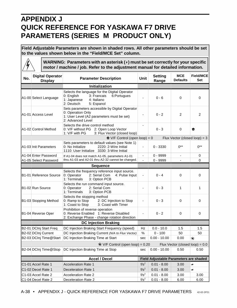
• APPENDIX J - QUICK REFERENCE FOR YASKAWA F7 DRIVE PARAMETERS 42-02-2P21A-38
WARNING: Parameters with an asterisk (u) must be set correctly for your specificmotor / machine / job. Refer to the adjustment manual for detailed information.
APPENDIX JQUICK REFERENCE FOR YASKAWA F7 DRIVEPARAMETERS (SERIES M PRODUCT ONLY)
Field Adjustable Parameters are shown in shaded rows. All other parameters should be setto the values shown below in the “Field/MCE Set” column.
No.Digital Operator
Display Parameter Description UnitSettingRange
MCEDefaults
Field/MCESet
Initialization
A1-00 Select Language
Selects the language for the Digital Operator0: English 3: Francais 6:Portugues1: Japanese 4: Italiano2: Deutsch 5: Espanol
- 0 - 6 0 0
A1-01 Access Level
Sets parameters accessible by Digital Operator0: Operation Only1: User Level (A2 parameters must be set)2: Advanced Level
- 0 - 2 2 2
A1-02 Control MethodSelects the drive control method 0: V/F without PG 2: Open Loop Vector1: V/F with PG 3: Flux Vector (closed loop)
-0 - 3 0
V/F Control (open loop) = 0 Flux Vector (closed loop) = 3
A1-03 Init ParametersSets parameters to default values (see Note 1)0: No Initialize 2220: 2-Wire Initial1110: User Initialize 3330: 3-Wire Initial
- 0 - 3330 0** 0**
A1-04 Enter Password If A1-04 does not match A1-05, parameters A1-01thru A1-03 and A2-01 thru A2-32 cannot be changed.
- 0 - 9999 - 0A1-05 Select Password - 0 - 9999 - 0
Sequence
B1-01 Reference SourceSelects the frequency reference input source.0: Operator 2: Serial Com 4: Pulse Input1: Terminals 3: Option PCB
- 0 - 4 0 0
B1-02 Run SourceSelects the run command input source.0: Operator 2: Serial Com1: Terminals 3: Option PCB
- 0 - 3 1 1
B1-03 Stopping MethodSelects the stopping method 0: Ramp to Stop 2: DC Injection to Stop1: Coast to Stop 3: Coast with Timer
- 0 - 3 0 0
B1-04 Reverse OperProhibition of reverse operation0: Reverse Enabled 1: Reverse Disabled2: Exchange Phase - change rotation direction
- 0 - 2 0 0
DC Injection BrakingB2-01 DCInj Start Freq DC Injection Braking Start Frequency (speed) Hz 0.0 - 10.0 1.5 1.5B2-02 DCInj Current DC Injection Braking Current (N/A to Flux Vector) % 0 - 100 50 50B2-03 DCInj Time@Start DC Injection Braking Time at Start sec 0.00 - 10.00 0.00 ‚
‚ V/F Control (open loop) = 0.20 Flux Vector (closed loop) = 0.0 B2-04 DCInj Time@Stop DC Injection Braking Time at Stop sec 0.00 - 10.00 0.50 0.50
Accel / Decel Field Adjustable Parameters are shaded
C1-01 Accel Rate 1 Acceleration Rate 1 f/s2 0.01 - 8.00 3.00 u
C1-02 Decel Rate 1 Deceleration Rate 1 f/s2 0.01 - 8.00 3.00 u
C1-03 Accel Rate 2 Acceleration Rate 2 f/s2 0.01 - 8.00 3.00 3.00C1-04 Decel Rate 2 Deceleration Rate 2 f/s2 0.01 - 8.00 6.00 6.00
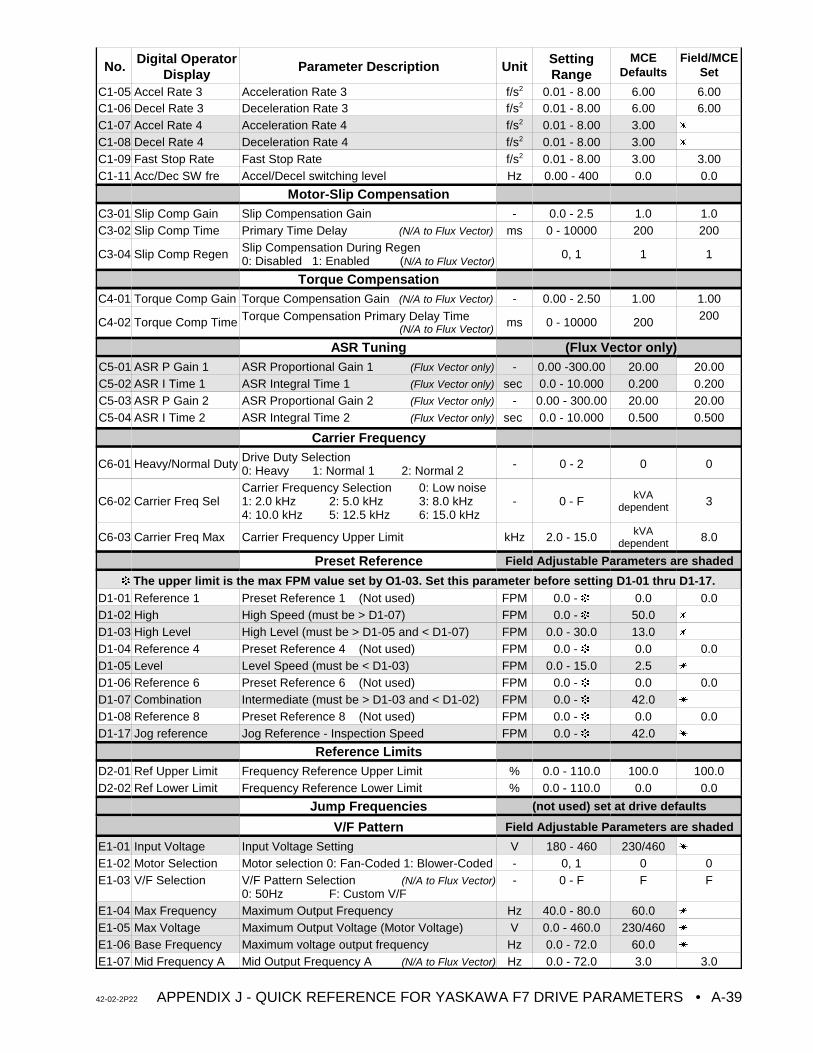
No. Digital OperatorDisplay
Parameter Description Unit SettingRange
MCEDefaults
Field/MCESet
42-02-2P22 APPENDIX J - QUICK REFERENCE FOR YASKAWA F7 DRIVE PARAMETERS • A-39
C1-05 Accel Rate 3 Acceleration Rate 3 f/s2 0.01 - 8.00 6.00 6.00C1-06 Decel Rate 3 Deceleration Rate 3 f/s2 0.01 - 8.00 6.00 6.00C1-07 Accel Rate 4 Acceleration Rate 4 f/s2 0.01 - 8.00 3.00 u
C1-08 Decel Rate 4 Deceleration Rate 4 f/s2 0.01 - 8.00 3.00 u
C1-09 Fast Stop Rate Fast Stop Rate f/s2 0.01 - 8.00 3.00 3.00C1-11 Acc/Dec SW fre Accel/Decel switching level Hz 0.00 - 400 0.0 0.0
Motor-Slip CompensationC3-01 Slip Comp Gain Slip Compensation Gain - 0.0 - 2.5 1.0 1.0C3-02 Slip Comp Time Primary Time Delay (N/A to Flux Vector) ms 0 - 10000 200 200
C3-04 Slip Comp Regen Slip Compensation During Regen 0: Disabled 1: Enabled (N/A to Flux Vector)
0, 1 1 1
Torque CompensationC4-01 Torque Comp Gain Torque Compensation Gain (N/A to Flux Vector) - 0.00 - 2.50 1.00 1.00
C4-02 Torque Comp Time Torque Compensation Primary Delay Time (N/A to Flux Vector)
ms 0 - 10000 200 200
ASR Tuning (Flux Vector only)C5-01 ASR P Gain 1 ASR Proportional Gain 1 (Flux Vector only) - 0.00 -300.00 20.00 20.00C5-02 ASR I Time 1 ASR Integral Time 1 (Flux Vector only) sec 0.0 - 10.000 0.200 0.200C5-03 ASR P Gain 2 ASR Proportional Gain 2 (Flux Vector only) - 0.00 - 300.00 20.00 20.00C5-04 ASR I Time 2 ASR Integral Time 2 (Flux Vector only) sec 0.0 - 10.000 0.500 0.500
Carrier Frequency
C6-01 Heavy/Normal Duty Drive Duty Selection0: Heavy 1: Normal 1 2: Normal 2 - 0 - 2 0 0
C6-02 Carrier Freq SelCarrier Frequency Selection 0: Low noise1: 2.0 kHz 2: 5.0 kHz 3: 8.0 kHz 4: 10.0 kHz 5: 12.5 kHz 6: 15.0 kHz
- 0 - F kVAdependent 3
C6-03 Carrier Freq Max Carrier Frequency Upper Limit kHz 2.0 - 15.0 kVAdependent 8.0
Preset Reference Field Adjustable Parameters are shaded
‹ The upper limit is the max FPM value set by O1-03. Set this parameter before setting D1-01 thru D1-17. D1-01 Reference 1 Preset Reference 1 (Not used) FPM 0.0 - ‹ 0.0 0.0D1-02 High High Speed (must be > D1-07) FPM 0.0 - ‹ 50.0 u
D1-03 High Level High Level (must be > D1-05 and < D1-07) FPM 0.0 - 30.0 13.0 u
D1-04 Reference 4 Preset Reference 4 (Not used) FPM 0.0 - ‹ 0.0 0.0D1-05 Level Level Speed (must be < D1-03) FPM 0.0 - 15.0 2.5 u
D1-06 Reference 6 Preset Reference 6 (Not used) FPM 0.0 - ‹ 0.0 0.0D1-07 Combination Intermediate (must be > D1-03 and < D1-02) FPM 0.0 - ‹ 42.0 u
D1-08 Reference 8 Preset Reference 8 (Not used) FPM 0.0 - ‹ 0.0 0.0D1-17 Jog reference Jog Reference - Inspection Speed FPM 0.0 - ‹ 42.0 u
Reference LimitsD2-01 Ref Upper Limit Frequency Reference Upper Limit % 0.0 - 110.0 100.0 100.0D2-02 Ref Lower Limit Frequency Reference Lower Limit % 0.0 - 110.0 0.0 0.0
Jump Frequencies (not used) set at drive defaults
V/F Pattern Field Adjustable Parameters are shaded
E1-01 Input Voltage Input Voltage Setting V 180 - 460 230/460 u
E1-02 Motor Selection Motor selection 0: Fan-Coded 1: Blower-Coded - 0, 1 0 0E1-03 V/F Selection V/F Pattern Selection (N/A to Flux Vector)
0: 50Hz F: Custom V/F- 0 - F F F
E1-04 Max Frequency Maximum Output Frequency Hz 40.0 - 80.0 60.0 u
E1-05 Max Voltage Maximum Output Voltage (Motor Voltage) V 0.0 - 460.0 230/460 u
E1-06 Base Frequency Maximum voltage output frequency Hz 0.0 - 72.0 60.0 u
E1-07 Mid Frequency A Mid Output Frequency A (N/A to Flux Vector) Hz 0.0 - 72.0 3.0 3.0
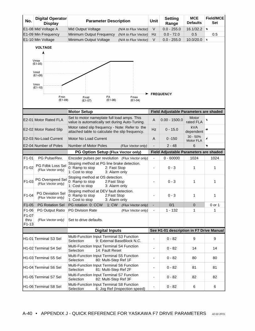
No. Digital OperatorDisplay
Parameter Description Unit SettingRange
MCEDefaults
Field/MCESet
• APPENDIX J - QUICK REFERENCE FOR YASKAWA F7 DRIVE PARAMETERS 42-02-2P21A-40
E1-08 Mid Voltage A Mid Output Voltage (N/A to Flux Vector) V 0.0 - 255.0 16.1/32.2 u
E1-09 Min Frequency Minimum Output Frequency (N/A to Flux Vector) Hz 0.0 - 72.0 0.5 0.5E1-10 Min Voltage Minimum Output Voltage (N/A to Flux Vector) V 0.0 - 255.0 10.0/20.0 u
Motor Setup Field Adjustable Parameters are shaded
E2-01 Motor Rated FLA Set to motor nameplate full load amps. Thisvalue is automatically set during Auto-Tuning. A 0.00 - 1500.0 Motor
rated FLA u
E2-02 Motor Rated Slip Motor rated slip frequency - Note: Refer to theattached table to calculate the slip frequency. Hz 0 - 15.0 kVA
dependent u
E2-03 No-Load Current Motor No Load Current A 0 -150 30 - 50%Motor FLA u
E2-04 Number of Poles Number of Motor Poles (Flux Vector only) - 2 - 48 6 u
PG Option Setup (Flux Vector only) Field Adjustable Parameters are shaded
F1-01 PG Pulse/Rev. Encoder pulses per revolution (Flux Vector only) - 0 - 60000 1024 1024
F1-02 PG Fdbk Loss Sel(Flux Vector only)
Stoping method at PG line brake detection.0: Ramp to stop 2: Fast Stop1: Cost to stop 3: Alarm only
- 0 - 3 1 1
F1-03 PG Overspeed Sel(Flux Vector only)
Stoping method at OS detection.0: Ramp to stop 2:Fast Stop1: Cost to stop 3: Alarm only
- 0 - 3 1 1
F1-04 PG Deviation Sel(Flux Vector only)
Stoping method at DEV fault detection.0: Ramp to stop 2:Fast Stop1: Cost to stop 3: Alarm only
- 0 - 3 1 1
F1-05 PG Rotation Sel PG rotation 0: CCW 1: CW (Flux Vector only) - 0/1 0 0 or 1F1-06 PG Output Ratio PG Division Rate (Flux Vector only) - 1 - 132 1 1F1-07thru
F1-13(Flux Vector only) Set to drive defaults.
Digital Inputs See H1-01 description in F7 Drive Manual
H1-01 Terminal S3 Sel Multi-Function Input Terminal S3 FunctionSelection 9: External BaseBlock N.C. - 0 - 82 9 9
H1-02 Terminal S4 Sel Multi-Function Input Terminal S4 FunctionSelection 14: Fault Reset - 0 - 82 14 14
H1-03 Terminal S5 Sel Multi-Function Input Terminal S5 FunctionSelection 80: Multi-Step Ref 1F - 0 - 82 80 80
H1-04 Terminal S6 Sel Multi-Function Input Terminal S6 FunctionSelection 81: Multi-Step Ref 2F - 0 - 82 81 81
H1-05 Terminal S7 Sel Multi-Function Input Terminal S7 FunctionSelection 82: Multi-Step Ref 3F - 0 - 82 82 82
H1-06 Terminal S8 Sel Multi-Function Input Terminal S8 FunctionSelection 6: Jog Ref (Inspection speed) - 0 - 82 6 6
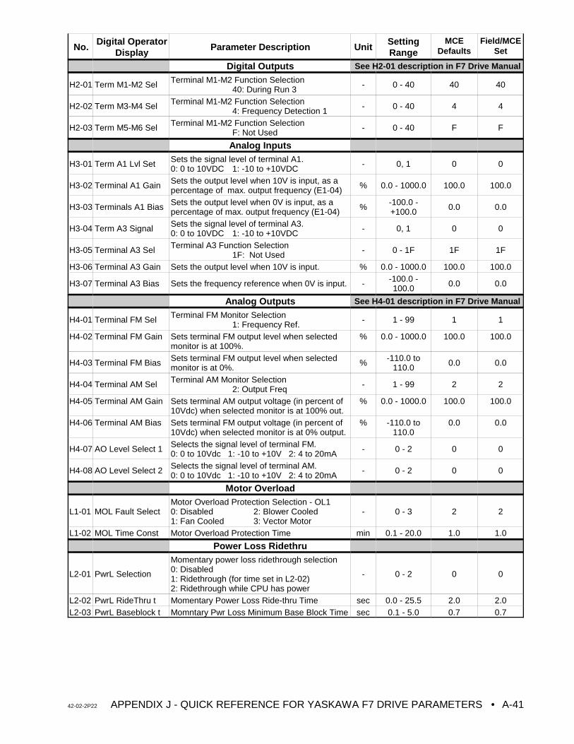
No. Digital OperatorDisplay
Parameter Description Unit SettingRange
MCEDefaults
Field/MCESet
42-02-2P22 APPENDIX J - QUICK REFERENCE FOR YASKAWA F7 DRIVE PARAMETERS • A-41
Digital Outputs See H2-01 description in F7 Drive Manual
H2-01 Term M1-M2 Sel Terminal M1-M2 Function Selection40: During Run 3 - 0 - 40 40 40
H2-02 Term M3-M4 Sel Terminal M1-M2 Function Selection4: Frequency Detection 1 - 0 - 40 4 4
H2-03 Term M5-M6 Sel Terminal M1-M2 Function SelectionF: Not Used - 0 - 40 F F
Analog Inputs
H3-01 Term A1 Lvl Set Sets the signal level of terminal A1.0: 0 to 10VDC 1: -10 to +10VDC - 0, 1 0 0
H3-02 Terminal A1 Gain Sets the output level when 10V is input, as apercentage of max. output frequency (E1-04) % 0.0 - 1000.0 100.0 100.0
H3-03 Terminals A1 Bias Sets the output level when 0V is input, as apercentage of max. output frequency (E1-04) % -100.0 -
+100.0 0.0 0.0
H3-04 Term A3 Signal Sets the signal level of terminal A3.0: 0 to 10VDC 1: -10 to +10VDC - 0, 1 0 0
H3-05 Terminal A3 Sel Terminal A3 Function Selection 1F: Not Used - 0 - 1F 1F 1F
H3-06 Terminal A3 Gain Sets the output level when 10V is input. % 0.0 - 1000.0 100.0 100.0
H3-07 Terminal A3 Bias Sets the frequency reference when 0V is input. - -100.0 -100.0 0.0 0.0
Analog Outputs See H4-01 description in F7 Drive Manual
H4-01 Terminal FM Sel Terminal FM Monitor Selection1: Frequency Ref. - 1 - 99 1 1
H4-02 Terminal FM Gain Sets terminal FM output level when selectedmonitor is at 100%.
% 0.0 - 1000.0 100.0 100.0
H4-03 Terminal FM Bias Sets terminal FM output level when selectedmonitor is at 0%. % -110.0 to
110.0 0.0 0.0
H4-04 Terminal AM Sel Terminal AM Monitor Selection2: Output Freq - 1 - 99 2 2
H4-05 Terminal AM Gain Sets terminal AM output voltage (in percent of10Vdc) when selected monitor is at 100% out.
% 0.0 - 1000.0 100.0 100.0
H4-06 Terminal AM Bias Sets terminal FM output voltage (in percent of10Vdc) when selected monitor is at 0% output.
% -110.0 to110.0
0.0 0.0
H4-07 AO Level Select 1 Selects the signal level of terminal FM.0: 0 to 10Vdc 1: -10 to +10V 2: 4 to 20mA - 0 - 2 0 0
H4-08 AO Level Select 2 Selects the signal level of terminal AM.0: 0 to 10Vdc 1: -10 to +10V 2: 4 to 20mA - 0 - 2 0 0
Motor Overload
L1-01 MOL Fault SelectMotor Overload Protection Selection - OL10: Disabled 2: Blower Cooled1: Fan Cooled 3: Vector Motor
- 0 - 3 2 2
L1-02 MOL Time Const Motor Overload Protection Time min 0.1 - 20.0 1.0 1.0
Power Loss Ridethru
L2-01 PwrL Selection
Momentary power loss ridethrough selection0: Disabled1: Ridethrough (for time set in L2-02)2: Ridethrough while CPU has power
- 0 - 2 0 0
L2-02 PwrL RideThru t Momentary Power Loss Ride-thru Time sec 0.0 - 25.5 2.0 2.0L2-03 PwrL Baseblock t Momntary Pwr Loss Minimum Base Block Time sec 0.1 - 5.0 0.7 0.7
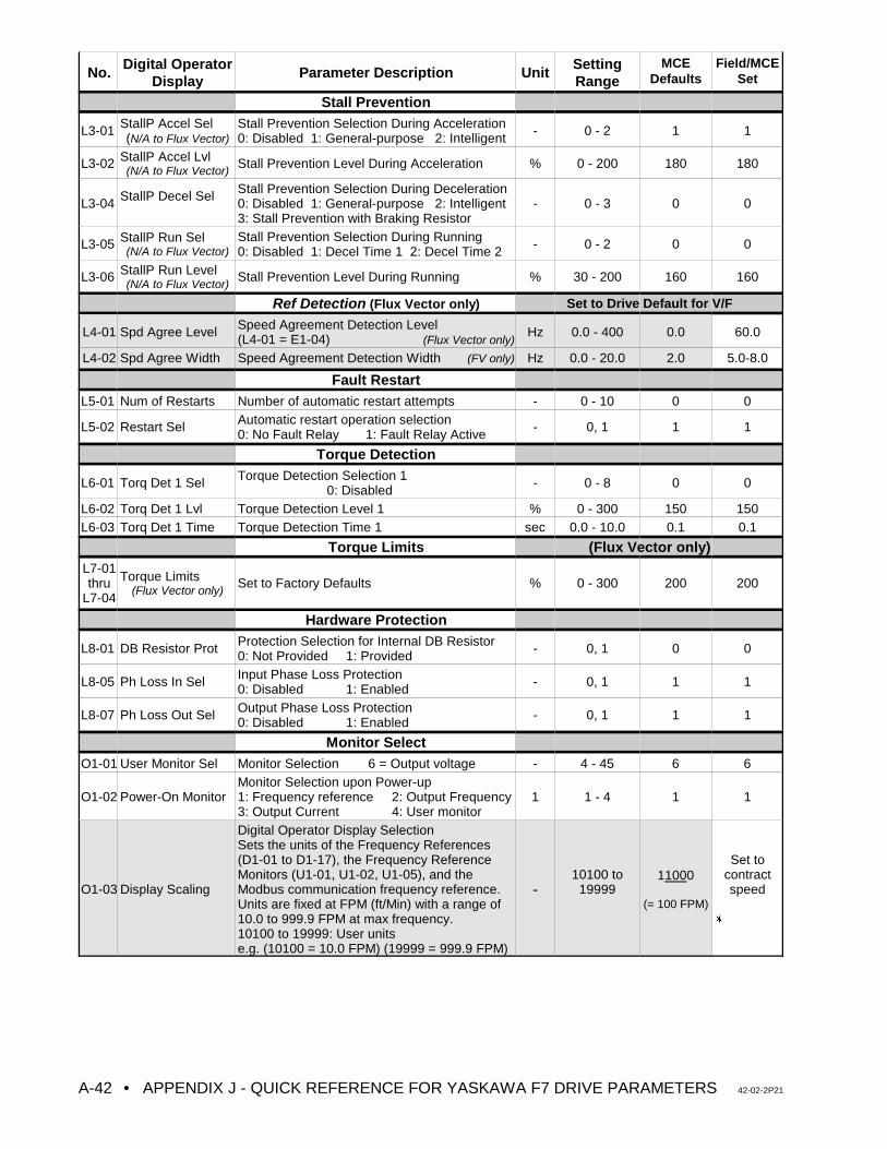
No. Digital OperatorDisplay
Parameter Description Unit SettingRange
MCEDefaults
Field/MCESet
• APPENDIX J - QUICK REFERENCE FOR YASKAWA F7 DRIVE PARAMETERS 42-02-2P21A-42
Stall Prevention
L3-01 StallP Accel Sel(N/A to Flux Vector)
Stall Prevention Selection During Acceleration0: Disabled 1: General-purpose 2: Intelligent - 0 - 2 1 1
L3-02 StallP Accel Lvl(N/A to Flux Vector)
Stall Prevention Level During Acceleration % 0 - 200 180 180
L3-04 StallP Decel Sel Stall Prevention Selection During Deceleration0: Disabled 1: General-purpose 2: Intelligent3: Stall Prevention with Braking Resistor
- 0 - 3 0 0
L3-05 StallP Run Sel(N/A to Flux Vector)
Stall Prevention Selection During Running0: Disabled 1: Decel Time 1 2: Decel Time 2 - 0 - 2 0 0
L3-06 StallP Run Level(N/A to Flux Vector)
Stall Prevention Level During Running % 30 - 200 160 160
Ref Detection (Flux Vector only) Set to Drive Default for V/F
L4-01 Spd Agree Level Speed Agreement Detection Level(L4-01 = E1-04) (Flux Vector only)
Hz 0.0 - 400 0.0 60.0
L4-02 Spd Agree Width Speed Agreement Detection Width (FV only) Hz 0.0 - 20.0 2.0 5.0-8.0
Fault RestartL5-01 Num of Restarts Number of automatic restart attempts - 0 - 10 0 0
L5-02 Restart Sel Automatic restart operation selection0: No Fault Relay 1: Fault Relay Active - 0, 1 1 1
Torque Detection
L6-01 Torq Det 1 Sel Torque Detection Selection 10: Disabled - 0 - 8 0 0
L6-02 Torq Det 1 Lvl Torque Detection Level 1 % 0 - 300 150 150L6-03 Torq Det 1 Time Torque Detection Time 1 sec 0.0 - 10.0 0.1 0.1
Torque Limits (Flux Vector only)L7-01thru
L7-04
Torque Limits(Flux Vector only)
Set to Factory Defaults % 0 - 300 200 200
Hardware Protection
L8-01 DB Resistor Prot Protection Selection for Internal DB Resistor0: Not Provided 1: Provided - 0, 1 0 0
L8-05 Ph Loss In Sel Input Phase Loss Protection0: Disabled 1: Enabled - 0, 1 1 1
L8-07 Ph Loss Out Sel Output Phase Loss Protection0: Disabled 1: Enabled - 0, 1 1 1
Monitor SelectO1-01 User Monitor Sel Monitor Selection 6 = Output voltage - 4 - 45 6 6
O1-02 Power-On MonitorMonitor Selection upon Power-up1: Frequency reference 2: Output Frequency3: Output Current 4: User monitor
1 1 - 4 1 1
O1-03 Display Scaling
Digital Operator Display SelectionSets the units of the Frequency References(D1-01 to D1-17), the Frequency ReferenceMonitors (U1-01, U1-02, U1-05), and theModbus communication frequency reference.Units are fixed at FPM (ft/Min) with a range of10.0 to 999.9 FPM at max frequency.10100 to 19999: User unitse.g. (10100 = 10.0 FPM) (19999 = 999.9 FPM)
-10100 to
1999911000
(= 100 FPM)
Set tocontractspeed
u
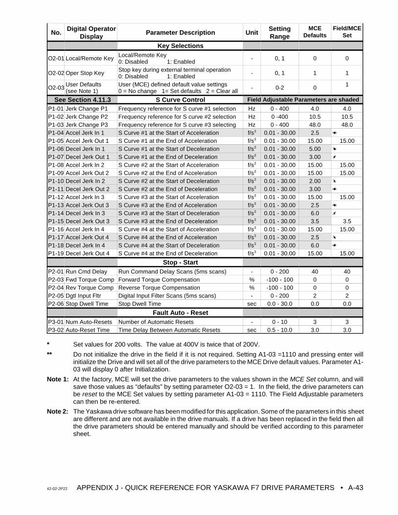
No. Digital OperatorDisplay
Parameter Description Unit SettingRange
MCEDefaults
Field/MCESet
42-02-2P22 APPENDIX J - QUICK REFERENCE FOR YASKAWA F7 DRIVE PARAMETERS • A-43
Key Selections
O2-01 Local/Remote Key Local/Remote Key0: Disabled 1: Enabled - 0, 1 0 0
O2-02 Oper Stop Key Stop key during external terminal operation0: Disabled 1: Enabled - 0, 1 1 1
O2-03 User Defaults(see Note 1)
User (MCE) defined default value settings0 = No change 1= Set defaults 2 = Clear all - 0-2 0 1
See Section 4.11.3 S Curve Control Field Adjustable Parameters are shaded
P1-01 Jerk Change P1 Frequency reference for S curve #1 selection Hz 0 - 400 4.0 4.0P1-02 Jerk Change P2 Frequency reference for S curve #2 selection Hz 0 -400 10.5 10.5P1-03 Jerk Change P3 Frequency reference for S curve #3 selecting Hz 0 - 400 48.0 48.0P1-04 Accel Jerk In 1 S Curve #1 at the Start of Acceleration f/s3 0.01 - 30.00 2.5 u
P1-05 Accel Jerk Out 1 S Curve #1 at the End of Acceleration f/s3 0.01 - 30.00 15.00 15.00P1-06 Decel Jerk In 1 S Curve #1 at the Start of Deceleration f/s3 0.01 - 30.00 5.00 u
P1-07 Decel Jerk Out 1 S Curve #1 at the End of Deceleration f/s3 0.01 - 30.00 3.00 u
P1-08 Accel Jerk In 2 S Curve #2 at the Start of Acceleration f/s3 0.01 - 30.00 15.00 15.00P1-09 Accel Jerk Out 2 S Curve #2 at the End of Acceleration f/s3 0.01 - 30.00 15.00 15.00P1-10 Decel Jerk In 2 S Curve #2 at the Start of Deceleration f/s3 0.01 - 30.00 2.00 u
P1-11 Decel Jerk Out 2 S Curve #2 at the End of Deceleration f/s3 0.01 - 30.00 3.00 u
P1-12 Accel Jerk In 3 S Curve #3 at the Start of Acceleration f/s3 0.01 - 30.00 15.00 15.00P1-13 Accel Jerk Out 3 S Curve #3 at the End of Acceleration f/s3 0.01 - 30.00 2.5 u
P1-14 Decel Jerk In 3 S Curve #3 at the Start of Deceleration f/s3 0.01 - 30.00 6.0 u
P1-15 Decel Jerk Out 3 S Curve #3 at the End of Deceleration f/s3 0.01 - 30.00 3.5 3.5P1-16 Accel Jerk In 4 S Curve #4 at the Start of Acceleration f/s3 0.01 - 30.00 15.00 15.00P1-17 Accel Jerk Out 4 S Curve #4 at the End of Acceleration f/s3 0.01 - 30.00 2.5 u
P1-18 Decel Jerk In 4 S Curve #4 at the Start of Deceleration f/s3 0.01 - 30.00 6.0 u
P1-19 Decel Jerk Out 4 S Curve #4 at the End of Deceleration f/s3 0.01 - 30.00 15.00 15.00
Stop - StartP2-01 Run Cmd Delay Run Command Delay Scans (5ms scans) - 0 - 200 40 40P2-03 Fwd Torque Comp Forward Torque Compensation % -100 - 100 0 0P2-04 Rev Torque Comp Reverse Torque Compensation % -100 - 100 0 0P2-05 Dgtl Input Fltr Digital Input Filter Scans (5ms scans) - 0 - 200 2 2P2-06 Stop Dwell Time Stop Dwell Time sec 0.0 - 30.0 0.0 0.0
Fault Auto - ResetP3-01 Num Auto-Resets Number of Automatic Resets - 0 - 10 3 3P3-02 Auto-Reset Time Time Delay Between Automatic Resets sec 0.5 - 10.0 3.0 3.0
* Set values for 200 volts. The value at 400V is twice that of 200V.
** Do not initialize the drive in the field if it is not required. Setting A1-03 =1110 and pressing enter willinitialize the Drive and will set all of the drive parameters to the MCE Drive default values. Parameter A1-03 will display 0 after Initialization.
Note 1: At the factory, MCE will set the drive parameters to the values shown in the MCE Set column, and willsave those values as “defaults” by setting parameter O2-03 = 1. In the field, the drive parameters canbe reset to the MCE Set values by setting parameter A1-03 = 1110. The Field Adjustable parameterscan then be re-entered.
Note 2: The Yaskawa drive software has been modified for this application. Some of the parameters in this sheetare different and are not available in the drive manuals. If a drive has been replaced in the field then allthe drive parameters should be entered manually and should be verified according to this parametersheet.
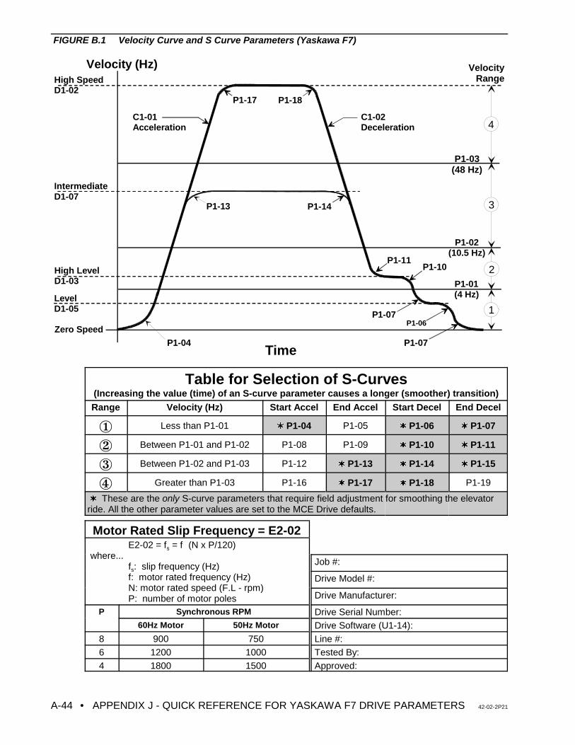
• APPENDIX J - QUICK REFERENCE FOR YASKAWA F7 DRIVE PARAMETERS 42-02-2P21A-44
Velocity (Hz)
Time
Zero Speed
Level D1-05
High LevelD1-03
IntermediateD1-07
High SpeedD1-02
P1-04
C1-01 Acceleration
C1-02 Deceleration
P1-13 P1-14
P1-11P1-10
P1-07P1-06
P1-07
P1-17 P1-18
P1-03 (48 Hz)
P1-02 (10.5 Hz)
P1-01 (4 Hz)
1
2
3
4
VelocityRange
FIGURE B.1 Velocity Curve and S Curve Parameters (Yaskawa F7)
Table for Selection of S-Curves(Increasing the value (time) of an S-curve parameter causes a longer (smoother) transition)Range Velocity (Hz) Start Accel End Accel Start Decel End Decel
Î Less than P1-01 w P1-04 P1-05 w P1-06 w P1-07
Ï Between P1-01 and P1-02 P1-08 P1-09 w P1-10 w P1-11
Ð Between P1-02 and P1-03 P1-12 w P1-13 w P1-14 w P1-15
Ñ Greater than P1-03 P1-16 w P1-17 w P1-18 P1-19
w These are the only S-curve parameters that require field adjustment for smoothing the elevatorride. All the other parameter values are set to the MCE Drive defaults.
Motor Rated Slip Frequency = E2-02E2-02 = fs = f!(N x P/120)
where...fs: slip frequency (Hz)f: motor rated frequency (Hz)N: motor rated speed (F.L - rpm)P: number of motor poles
Job #:
Drive Model #:
Drive Manufacturer:
P Synchronous RPM Drive Serial Number:60Hz Motor 50Hz Motor Drive Software (U1-14):
8 900 750 Line #:6 1200 1000 Tested By:4 1800 1500 Approved:
42-02-2P22 APPENDIX K - POWERBACK R6 REGENERATIVE DRIVE • A-45
APPENDIX KQUICK REFERENCE FOR POWERBACK R6 REGENERATIVE AC DRIVE PARAMETERS (SERIES M and IMC-AC-R)
K.1 GENERAL
The following information pertains to VVMC-1000-PTC Series M controllers with the additionof the POWERBACK R6 Regenerative Drive.
K.2 REGENERATIVE DRIVE INTERFACE
The following is an explanation of the POWERBACK R6 Regenerative Drive interface.
DRIVE INPUTS
• Drive Enable (Terminal 12): This input enables the R6 drive and puts the drive instandby mode. Drive parameter ru. 0 reads stby during motoring condition and Active during deceleration/overhauling conditions. A voltage between drive terminals12 & 17 of 18 VDC = ON, 0 VAC = OFF.
• Drive Reset (Terminal 13): This input resets an R6 drive fault. Pressing the drivereset button on the HC-ACI board activates the reset input and clears regenerativedrive faults. A voltage between drive terminal 13 & 17 of 18 VDC = ON, 0 VAC =OFF.
DRIVE OUTPUT
• Drive ready contact: The contacts between terminals 24 and 26 on the R6 driveremain closed under normal condition and open during a fault, which drops the RDYrelay on the HC-ACI board. Pressing the Drive Reset button on the HC-ACI boardshould clear the R6 drive fault and should turn ON the RDY relay.
POWER CONNECTIONS
• Make sure synchronization cable is connected between the commutation choke andthe R6 drive.
• The DC bus connections must be correct and according to the drawings. It is
critical that DC bus connections be correct. Incorrect connections will damagethe drive units.
• The line inductor ground connection to the R6 Drive and F5 Drive must becompleted according to the drawings.
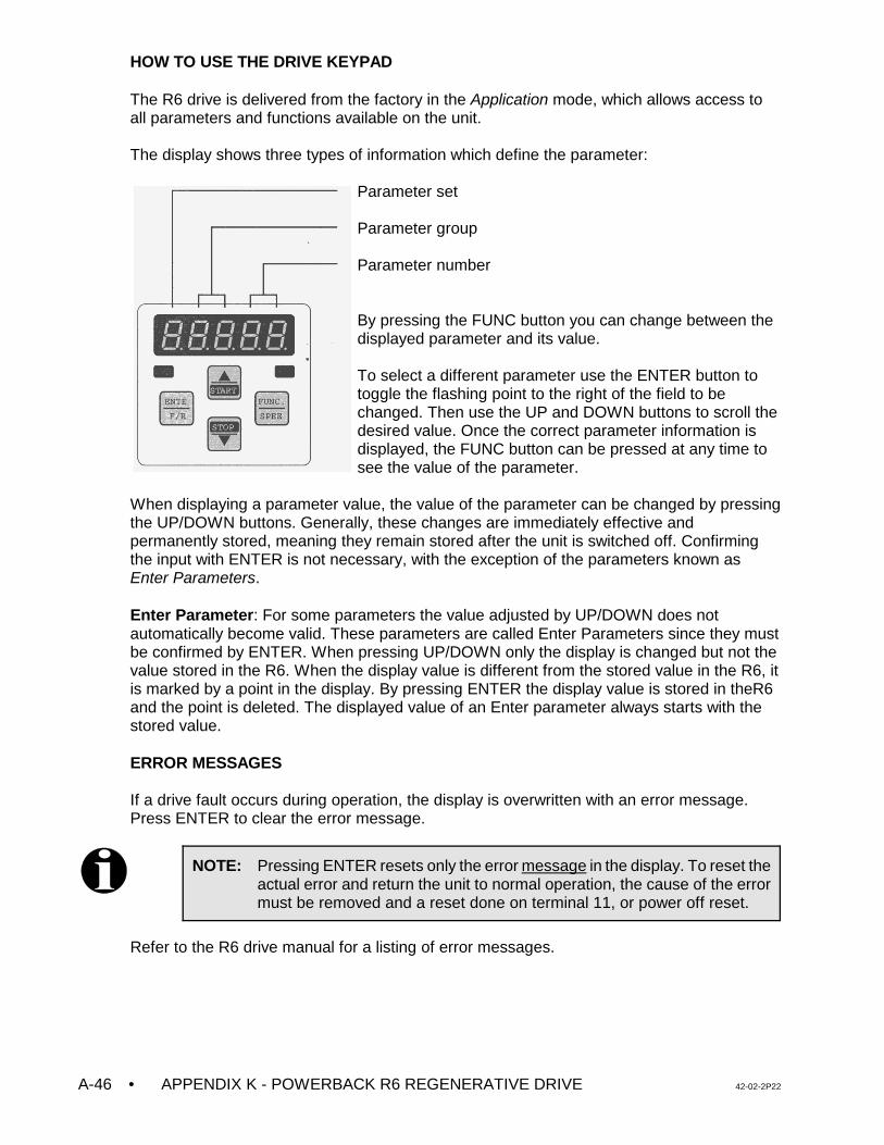
• APPENDIX K - POWERBACK R6 REGENERATIVE DRIVE 42-02-2P22A-46
NOTE: Pressing ENTER resets only the error message in the display. To reset theactual error and return the unit to normal operation, the cause of the errormust be removed and a reset done on terminal 11, or power off reset.
HOW TO USE THE DRIVE KEYPAD
The R6 drive is delivered from the factory in the Application mode, which allows access toall parameters and functions available on the unit.
The display shows three types of information which define the parameter:
Parameter set
Parameter group
Parameter number
By pressing the FUNC button you can change between thedisplayed parameter and its value.
To select a different parameter use the ENTER button totoggle the flashing point to the right of the field to bechanged. Then use the UP and DOWN buttons to scroll thedesired value. Once the correct parameter information isdisplayed, the FUNC button can be pressed at any time tosee the value of the parameter.
When displaying a parameter value, the value of the parameter can be changed by pressingthe UP/DOWN buttons. Generally, these changes are immediately effective andpermanently stored, meaning they remain stored after the unit is switched off. Confirmingthe input with ENTER is not necessary, with the exception of the parameters known asEnter Parameters.
Enter Parameter: For some parameters the value adjusted by UP/DOWN does notautomatically become valid. These parameters are called Enter Parameters since they mustbe confirmed by ENTER. When pressing UP/DOWN only the display is changed but not thevalue stored in the R6. When the display value is different from the stored value in the R6, itis marked by a point in the display. By pressing ENTER the display value is stored in theR6and the point is deleted. The displayed value of an Enter parameter always starts with thestored value.
ERROR MESSAGES
If a drive fault occurs during operation, the display is overwritten with an error message.Press ENTER to clear the error message.
Refer to the R6 drive manual for a listing of error messages.
42-02-2P22 APPENDIX K - POWERBACK R6 REGENERATIVE DRIVE • A-47
K.3 TURN ON PROCEDURE
The Powerback R6 is initialized after connection of the main line supply. The power circuitidentification is checked first. If an invalid power circuit is recognized, error E.PuCi (powerunit check) is triggered and displayed in the operator. This error cannot be reset, the powercircuit must be checked.
If a valid power circuit is recognized, the Powerback R6 changes into status "Syn". Thefollowing procedures take place one after another during this synchronisation phase:
• Verification of correct synchronisation to the line, (error E.nEt is triggered if thesynchronization signals are missing)
• Verification of the phasing of the synchronization signals to the main line phases. ErrorE.Syn is triggered if a phase signal is missing or in case the phasing is not correct.
• The actual line frequency is determined. If the frequency is outside the set window theunit will trigger an E.FnEt fault.
• The unit is now ready for operation. If the enable (terminal I1) is activated, thePowerback R6 is put into operation. Depending on the actual value of the DC busvoltage, the Powerback R6 is in status rEgEn or Stdby.
Status Stdby - Powerback R6 detects the idle voltage level in the DC bus circuit of theconnected frequency inverter (motor operation) and keeps the modulation signals of theregen unit deactivated.
Status rEgEn - If the DC bus voltage rises above 103% of the idle voltage (CP.9), themodulation signals are activated and the unit changes into regen operation. Alternately, ifanother R6 unit connected in parallel switches into rEgEn mode, the slave unit willimmediately switch into regen mode simultaneously.
CP.34 Control Angle Parameter
This parameter adjusts the conduction angle during regen mode. The default value is 30.0degrees. By lowering this value, the audible sound from the commutation choke can bereduced. The typical adjustment range is 25.0 to 30.0 degrees. Values higher than 36 canresult in random E.OC errors. Values lower than 25 can limit the available regen power.
Troubleshooting
Problem Cause Solution
During paralleloperation, loadsharing betweenunits is not equal.
Can be caused by tolerances between thevoltage circuit in the choke, the choke itself andthe voltage sensing circuit in the R6 unit. As aresult more current flows through that unit.
If the unit has version 1.3 software,lower the value of CP.34, on theunit with the highest load, in stepsof 1.0, until the load between thetwo balances out.
Audible noisefrom the choke istoo loud.
The default adjustment of the R6 unit allows forfast response and high peak capacity. This canlead to more audible noise from the choke. Byreducing the commutation angle, it is possible tolower this sound.
If the unit has version 1.3 software,lower the value of parameter CP.34from 30.0 to 26.0. Run the car at fullload to make sure there are noissues running full load down.
PARAMETER SETTING / ADJUSTMENT
The R6 drive parameters listed below are set at MCE and no field adjustments arenecessary. The parameter explanation is only for reference.
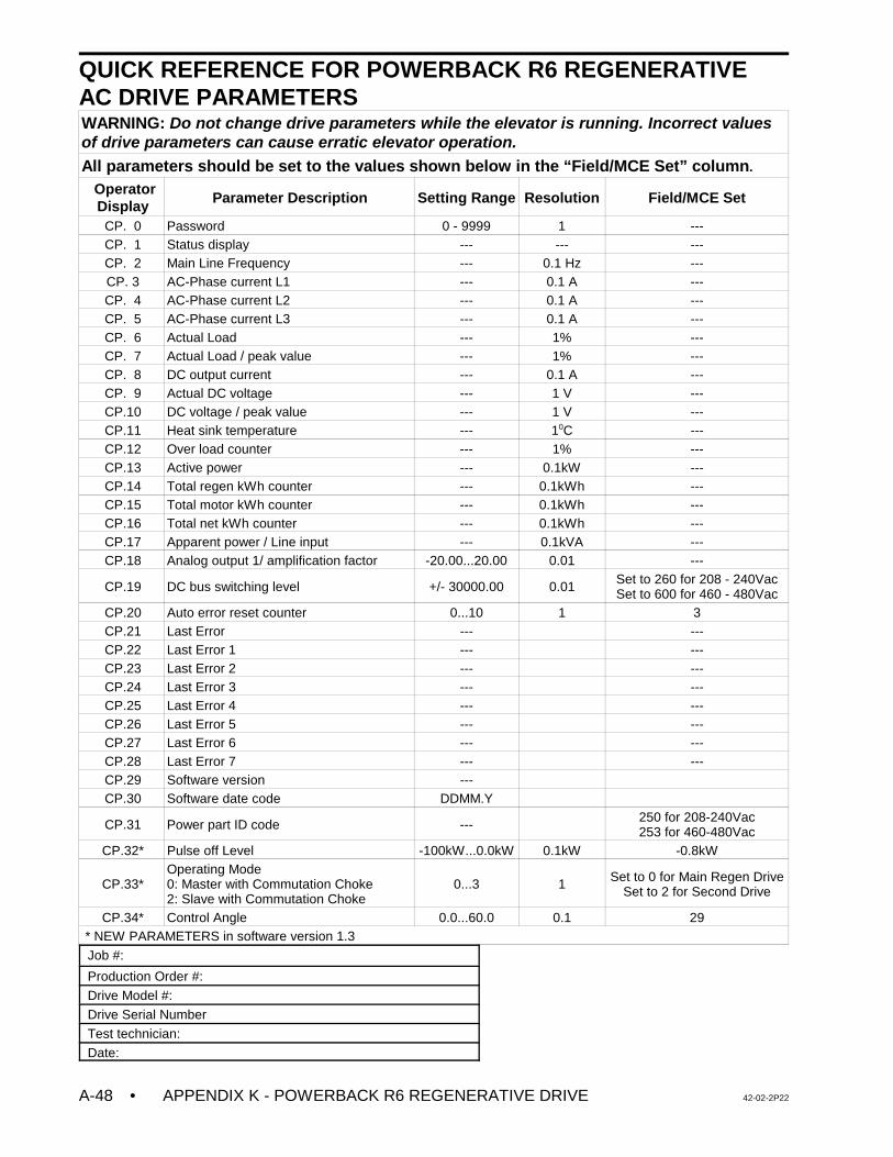
• APPENDIX K - POWERBACK R6 REGENERATIVE DRIVE 42-02-2P22A-48
QUICK REFERENCE FOR POWERBACK R6 REGENERATIVE AC DRIVE PARAMETERSWARNING: Do not change drive parameters while the elevator is running. Incorrect valuesof drive parameters can cause erratic elevator operation.All parameters should be set to the values shown below in the “Field/MCE Set” column.
OperatorDisplay Parameter Description Setting Range Resolution Field/MCE Set
CP. 0 Password 0 - 9999 1 ---CP. 1 Status display --- --- ---CP. 2 Main Line Frequency --- 0.1 Hz ---CP. 3 AC-Phase current L1 --- 0.1 A ---CP. 4 AC-Phase current L2 --- 0.1 A ---CP. 5 AC-Phase current L3 --- 0.1 A ---CP. 6 Actual Load --- 1% ---CP. 7 Actual Load / peak value --- 1% ---CP. 8 DC output current --- 0.1 A ---CP. 9 Actual DC voltage --- 1 V ---CP.10 DC voltage / peak value --- 1 V ---CP.11 Heat sink temperature --- 10C ---CP.12 Over load counter --- 1% ---CP.13 Active power --- 0.1kW ---CP.14 Total regen kWh counter --- 0.1kWh ---CP.15 Total motor kWh counter --- 0.1kWh ---CP.16 Total net kWh counter --- 0.1kWh ---CP.17 Apparent power / Line input --- 0.1kVA ---CP.18 Analog output 1/ amplification factor -20.00...20.00 0.01 ---
CP.19 DC bus switching level +/- 30000.00 0.01 Set to 260 for 208 - 240VacSet to 600 for 460 - 480Vac
CP.20 Auto error reset counter 0...10 1 3CP.21 Last Error --- ---CP.22 Last Error 1 --- ---CP.23 Last Error 2 --- ---CP.24 Last Error 3 --- ---CP.25 Last Error 4 --- ---CP.26 Last Error 5 --- ---CP.27 Last Error 6 --- ---CP.28 Last Error 7 --- ---CP.29 Software version ---CP.30 Software date code DDMM.Y
CP.31 Power part ID code --- 250 for 208-240Vac253 for 460-480Vac
CP.32* Pulse off Level -100kW...0.0kW 0.1kW -0.8kW
CP.33*Operating Mode0: Master with Commutation Choke2: Slave with Commutation Choke
0...3 1 Set to 0 for Main Regen DriveSet to 2 for Second Drive
CP.34* Control Angle 0.0...60.0 0.1 29 * NEW PARAMETERS in software version 1.3
Job #:
Production Order #:
Drive Model #:
Drive Serial Number
Test technician:
Date:
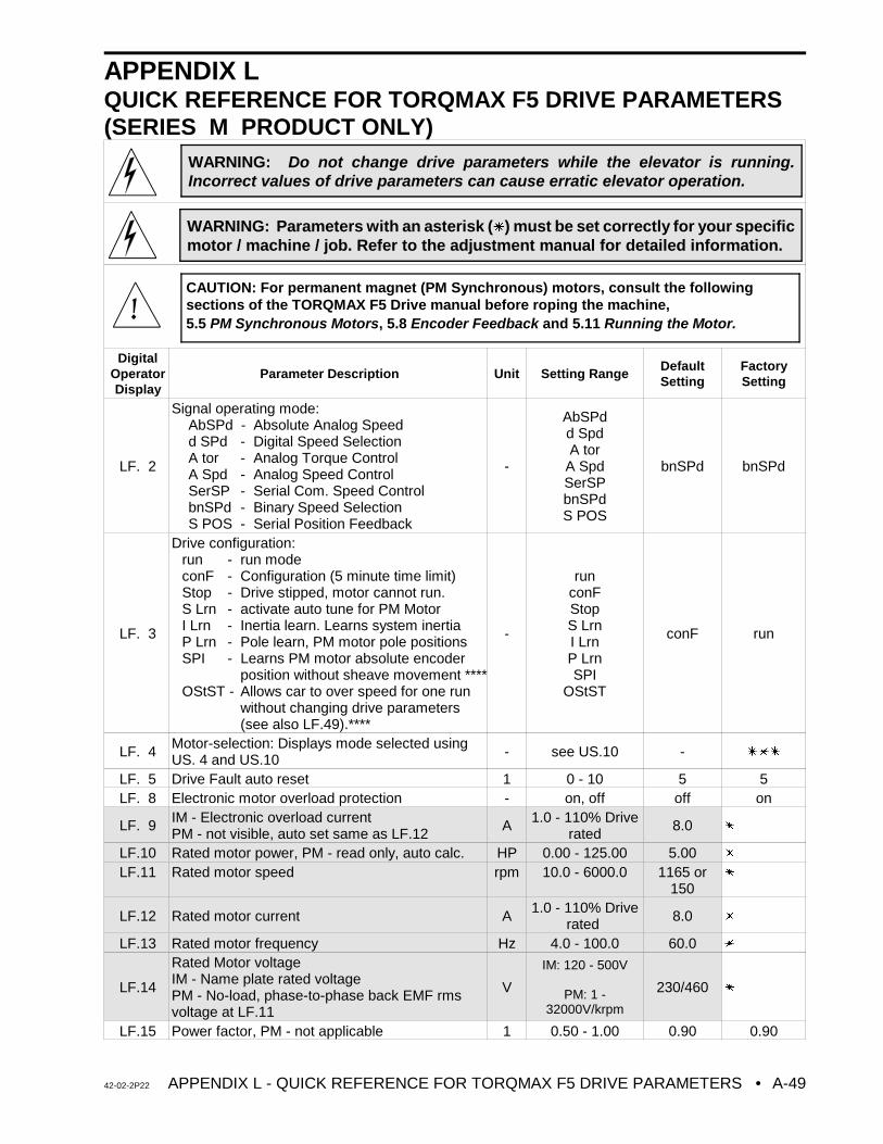
42-02-2P22 APPENDIX L - QUICK REFERENCE FOR TORQMAX F5 DRIVE PARAMETERS • A-49
WARNING: Do not change drive parameters while the elevator is running.Incorrect values of drive parameters can cause erratic elevator operation.
WARNING: Parameters with an asterisk (u) must be set correctly for your specificmotor / machine / job. Refer to the adjustment manual for detailed information.
APPENDIX LQUICK REFERENCE FOR TORQMAX F5 DRIVE PARAMETERS(SERIES M PRODUCT ONLY)
DigitalOperatorDisplay
Parameter Description Unit Setting RangeDefaultSetting
FactorySetting
LF. 2
Signal operating mode: AbSPd - Absolute Analog Speedd SPd - Digital Speed SelectionA tor - Analog Torque ControlA Spd - Analog Speed ControlSerSP - Serial Com. Speed ControlbnSPd - Binary Speed SelectionS POS - Serial Position Feedback
-
AbSPdd SpdA tor
A SpdSerSPbnSPdS POS
bnSPd bnSPd
LF. 3
Drive configuration: run - run modeconF - Configuration (5 minute time limit)Stop - Drive stipped, motor cannot run.S Lrn - activate auto tune for PM MotorI Lrn - Inertia learn. Learns system inertiaP Lrn - Pole learn, PM motor pole positionsSPI - Learns PM motor absolute encoder
position without sheave movement ****OStST - Allows car to over speed for one run
without changing drive parameters(see also LF.49).****
-
runconFStopS LrnI LrnP LrnSPI
OStST
conF run
LF. 4Motor-selection: Displays mode selected usingUS. 4 and US.10 - see US.10 - uuu
LF. 5 Drive Fault auto reset 1 0 - 10 5 5LF. 8 Electronic motor overload protection - on, off off on
LF. 9 IM - Electronic overload currentPM - not visible, auto set same as LF.12
A 1.0 - 110% Driverated
8.0 u
LF.10 Rated motor power, PM - read only, auto calc. HP 0.00 - 125.00 5.00 u LF.11 Rated motor speed rpm 10.0 - 6000.0 1165 or
150u
LF.12 Rated motor current A1.0 - 110% Drive
rated 8.0 u
LF.13 Rated motor frequency Hz 4.0 - 100.0 60.0 u
LF.14
Rated Motor voltageIM - Name plate rated voltagePM - No-load, phase-to-phase back EMF rmsvoltage at LF.11
V
IM: 120 - 500V
PM: 1 -32000V/krpm
230/460 u
LF.15 Power factor, PM - not applicable 1 0.50 - 1.00 0.90 0.90
CAUTION: For permanent magnet (PM Synchronous) motors, consult the followingsections of the TORQMAX F5 Drive manual before roping the machine,5.5 PM Synchronous Motors, 5.8 Encoder Feedback and 5.11 Running the Motor.
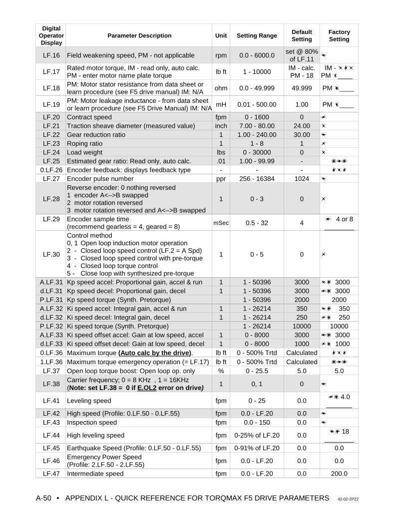
DigitalOperatorDisplay
Parameter Description Unit Setting RangeDefaultSetting
FactorySetting
• APPENDIX L - QUICK REFERENCE FOR TORQMAX F5 DRIVE PARAMETERS 42-02-2P22A-50
LF.16 Field weakening speed, PM - not applicable rpm 0.0 - 6000.0 set @ 80%of LF.11
u
LF.17Rated motor torque, IM - read only, auto calc.PM - enter motor name plate torque lb ft 1 - 10000
IM - calc.PM - 18
IM - uuuPM u____
LF.18 PM: Motor stator resistance from data sheet orlearn procedure (see F5 drive manual) IM: N/A
ohm 0.0 - 49.999 49.999 PM u____
LF.19PM: Motor leakage inductance - from data sheetor learn procedure (see F5 Drive Manual) IM: N/A mH 0.01 - 500.00 1.00 PM u____
LF.20 Contract speed fpm 0 - 1600 0 u
LF.21 Traction sheave diameter (measured value) inch 7.00 - 80.00 24.00 u
LF.22 Gear reduction ratio 1 1.00 - 240.00 30.00 u LF.23 Roping ratio 1 1 - 8 1 u
LF.24 Load weight lbs 0 - 30000 0 u
LF.25 Estimated gear ratio: Read only, auto calc. .01 1.00 - 99.99 - uuu
0.LF.26 Encoder feedback: displays feedback type - - - uuu
LF.27 Encoder pulse number ppr 256 - 16384 1024 u
LF.28
Reverse encoder: 0 nothing reversed 1 encoder A<–>B swapped2 motor rotation reversed3 motor rotation reversed and A<–>B swapped
1 0 - 3 0 u
LF.29 Encoder sample time(recommend gearless = 4, geared = 8)
mSec 0.5 - 32 4u 4 or 8________
LF.30
Control method 0, 1 Open loop induction motor operation2 - Closed loop speed control (LF.2 = A Spd)3 - Closed loop speed control with pre-torque4 - Closed loop torque control5 - Close loop with synthesized pre-torque
1 0 - 5 0 u
A.LF.31 Kp speed accel: Proportional gain, accel & run 1 1 - 50396 3000 uu 3000d.LF.31 Kp speed decel: Proportional gain, decel 1 1 - 50396 3000 uu 3000P.LF.31 Kp speed torque (Synth. Pretorque) 1 - 50396 2000 2000A.LF.32 Ki speed accel: Integral gain, accel & run 1 1 - 26214 350 uu 350 d.LF.32 Ki speed decel: Integral gain, decel 1 1 - 26214 250 uu 250P.LF.32 Ki speed torque (Synth. Pretorque) 1 - 26214 10000 10000A.LF.33 Ki speed offset accel: Gain at low speed, accel 1 0 - 8000 3000 uu 3000d.LF.33 Ki speed offset decel: Gain at low speed, decel 1 0 - 8000 1000 uu 10000.LF.36 Maximum torque (Auto calc by the drive). lb ft 0 - 500% Trtd Calculated uuu
1.LF.36 Maximum torque emergency operation (= LF.17) lb ft 0 - 500% Trtd Calculated uuu
LF.37 Open loop torque boost: Open loop op. only % 0 - 25.5 5.0 5.0
LF.38Carrier frequency; 0 = 8 KHz , 1 = 16KHz (Note: set LF.38 = 0 if E.OL2 error on drive) 1 0, 1 0 u
LF.41 Leveling speed fpm 0 - 25 0.0uu 4.0
_______LF.42 High speed (Profile: 0.LF.50 - 0.LF.55) fpm 0.0 - LF.20 0.0 u
LF.43 Inspection speed fpm 0.0 - 150 0.0 u
LF.44 High leveling speed fpm 0-25% of LF.20 0.0uu 18
________LF.45 Earthquake Speed (Profile: 0.LF.50 - 0.LF.55) fpm 0-91% of LF.20 0.0 0.0
LF.46Emergency Power Speed (Profile: 2.LF.50 - 2.LF.55) fpm 0.0 - LF.20 0.0 0.0
LF.47 Intermediate speed fpm 0.0 - LF.20 0.0 200.0
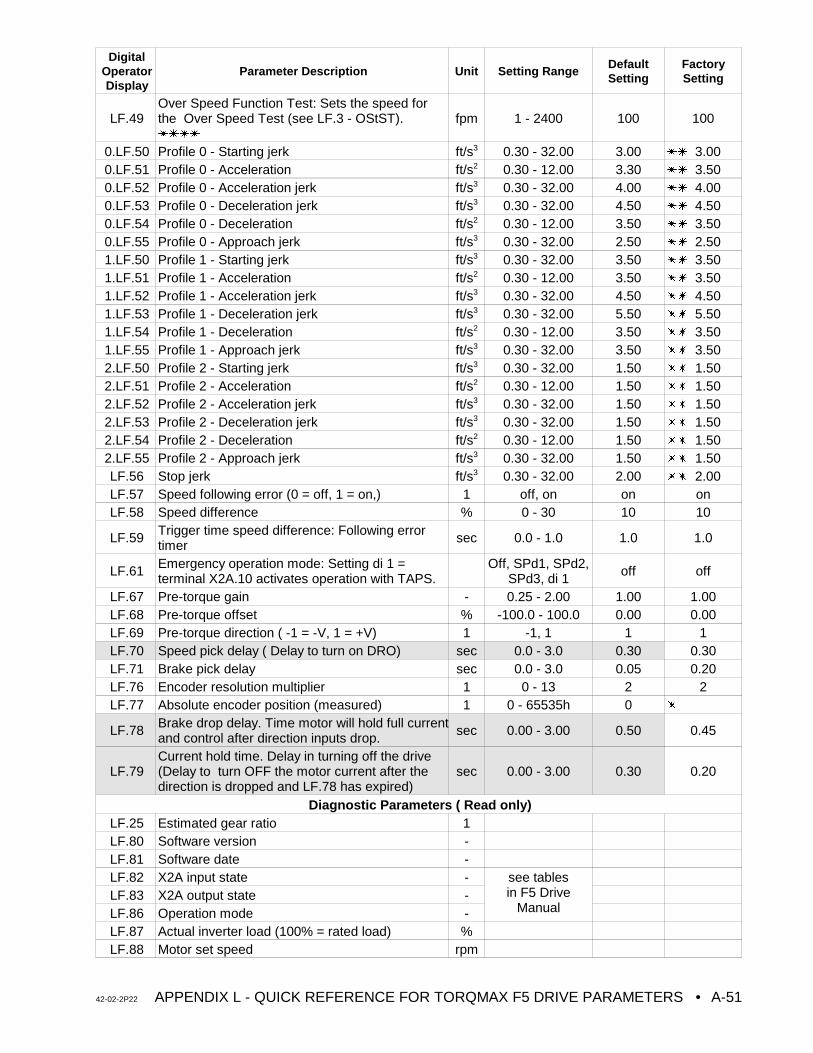
DigitalOperatorDisplay
Parameter Description Unit Setting RangeDefaultSetting
FactorySetting
42-02-2P22 APPENDIX L - QUICK REFERENCE FOR TORQMAX F5 DRIVE PARAMETERS • A-51
LF.49Over Speed Function Test: Sets the speed forthe Over Speed Test (see LF.3 - OStST).uuuu
fpm 1 - 2400 100 100
0.LF.50 Profile 0 - Starting jerk ft/s3 0.30 - 32.00 3.00 uu 3.000.LF.51 Profile 0 - Acceleration ft/s2 0.30 - 12.00 3.30 uu 3.500.LF.52 Profile 0 - Acceleration jerk ft/s3 0.30 - 32.00 4.00 uu 4.000.LF.53 Profile 0 - Deceleration jerk ft/s3 0.30 - 32.00 4.50 uu 4.500.LF.54 Profile 0 - Deceleration ft/s2 0.30 - 12.00 3.50 uu 3.500.LF.55 Profile 0 - Approach jerk ft/s3 0.30 - 32.00 2.50 uu 2.501.LF.50 Profile 1 - Starting jerk ft/s3 0.30 - 32.00 3.50 uu 3.501.LF.51 Profile 1 - Acceleration ft/s2 0.30 - 12.00 3.50 uu 3.501.LF.52 Profile 1 - Acceleration jerk ft/s3 0.30 - 32.00 4.50 uu 4.501.LF.53 Profile 1 - Deceleration jerk ft/s3 0.30 - 32.00 5.50 uu 5.501.LF.54 Profile 1 - Deceleration ft/s2 0.30 - 12.00 3.50 uu 3.501.LF.55 Profile 1 - Approach jerk ft/s3 0.30 - 32.00 3.50 uu 3.502.LF.50 Profile 2 - Starting jerk ft/s3 0.30 - 32.00 1.50 uu 1.502.LF.51 Profile 2 - Acceleration ft/s2 0.30 - 12.00 1.50 uu 1.502.LF.52 Profile 2 - Acceleration jerk ft/s3 0.30 - 32.00 1.50 uu 1.502.LF.53 Profile 2 - Deceleration jerk ft/s3 0.30 - 32.00 1.50 uu 1.502.LF.54 Profile 2 - Deceleration ft/s2 0.30 - 12.00 1.50 uu 1.502.LF.55 Profile 2 - Approach jerk ft/s3 0.30 - 32.00 1.50 uu 1.50LF.56 Stop jerk ft/s3 0.30 - 32.00 2.00 uu 2.00LF.57 Speed following error (0 = off, 1 = on,) 1 off, on on onLF.58 Speed difference % 0 - 30 10 10
LF.59 Trigger time speed difference: Following errortimer
sec 0.0 - 1.0 1.0 1.0
LF.61 Emergency operation mode: Setting di 1 =terminal X2A.10 activates operation with TAPS.
Off, SPd1, SPd2,SPd3, di 1
off off
LF.67 Pre-torque gain - 0.25 - 2.00 1.00 1.00LF.68 Pre-torque offset % -100.0 - 100.0 0.00 0.00LF.69 Pre-torque direction ( -1 = -V, 1 = +V) 1 -1, 1 1 1LF.70 Speed pick delay ( Delay to turn on DRO) sec 0.0 - 3.0 0.30 0.30LF.71 Brake pick delay sec 0.0 - 3.0 0.05 0.20LF.76 Encoder resolution multiplier 1 0 - 13 2 2LF.77 Absolute encoder position (measured) 1 0 - 65535h 0 u
LF.78 Brake drop delay. Time motor will hold full currentand control after direction inputs drop.
sec 0.00 - 3.00 0.50 0.45
LF.79Current hold time. Delay in turning off the drive(Delay to turn OFF the motor current after thedirection is dropped and LF.78 has expired)
sec 0.00 - 3.00 0.30 0.20
Diagnostic Parameters ( Read only)LF.25 Estimated gear ratio 1LF.80 Software version -LF.81 Software date -LF.82 X2A input state - see tables
in F5 DriveManual
LF.83 X2A output state -LF.86 Operation mode -LF.87 Actual inverter load (100% = rated load) %LF.88 Motor set speed rpm
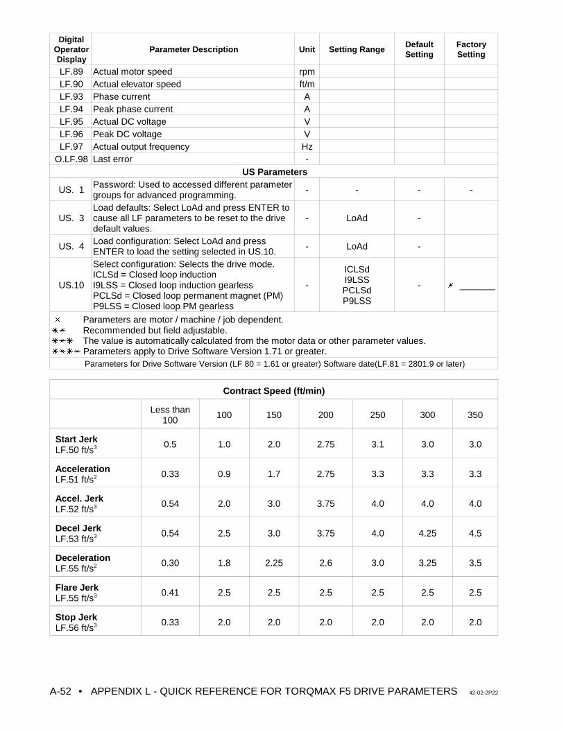
DigitalOperatorDisplay
Parameter Description Unit Setting RangeDefaultSetting
FactorySetting
• APPENDIX L - QUICK REFERENCE FOR TORQMAX F5 DRIVE PARAMETERS 42-02-2P22A-52
LF.89 Actual motor speed rpmLF.90 Actual elevator speed ft/mLF.93 Phase current ALF.94 Peak phase current ALF.95 Actual DC voltage VLF.96 Peak DC voltage VLF.97 Actual output frequency Hz
O.LF.98 Last error -US Parameters
US. 1 Password: Used to accessed different parametergroups for advanced programming.
- - - -
US. 3Load defaults: Select LoAd and press ENTER tocause all LF parameters to be reset to the drivedefault values.
- LoAd -
US. 4 Load configuration: Select LoAd and pressENTER to load the setting selected in US.10.
- LoAd -
US.10
Select configuration: Selects the drive mode.ICLSd = Closed loop inductionI9LSS = Closed loop induction gearlessPCLSd = Closed loop permanent magnet (PM)P9LSS = Closed loop PM gearless
-
ICLSdI9LSSPCLSdP9LSS
- u _______
u Parameters are motor / machine / job dependent.uu Recommended but field adjustable.uuu The value is automatically calculated from the motor data or other parameter values.uuuu Parameters apply to Drive Software Version 1.71 or greater.
Parameters for Drive Software Version (LF 80 = 1.61 or greater) Software date(LF.81 = 2801.9 or later)
Contract Speed (ft/min)
Less than100
100 150 200 250 300 350
Start JerkLF.50 ft/s3 0.5 1.0 2.0 2.75 3.1 3.0 3.0
AccelerationLF.51 ft/s2 0.33 0.9 1.7 2.75 3.3 3.3 3.3
Accel. JerkLF.52 ft/s3 0.54 2.0 3.0 3.75 4.0 4.0 4.0
Decel JerkLF.53 ft/s3 0.54 2.5 3.0 3.75 4.0 4.25 4.5
DecelerationLF.55 ft/s2 0.30 1.8 2.25 2.6 3.0 3.25 3.5
Flare JerkLF.55 ft/s3 0.41 2.5 2.5 2.5 2.5 2.5 2.5
Stop JerkLF.56 ft/s3 0.33 2.0 2.0 2.0 2.0 2.0 2.0
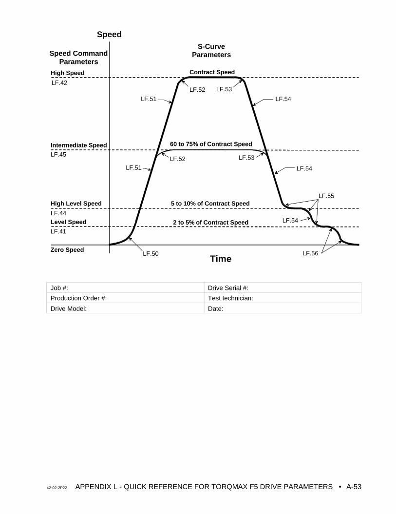
42-02-2P22 APPENDIX L - QUICK REFERENCE FOR TORQMAX F5 DRIVE PARAMETERS • A-53
Speed
TimeZero Speed
Level Speed
High Level Speed
Intermediate Speed
High Speed
LF.50
LF.51 LF.54
LF.56
LF.52
LF.52
LF.55
LF.53
Contract Speed
5 to 10% of Contract Speed
2 to 5% of Contract Speed
Speed CommandParameters
S-CurveParameters
LF.54
LF.54LF.51
60 to 75% of Contract Speed
LF.42
LF.45
LF.44
LF.41
LF.53
Job #: Drive Serial #:
Production Order #: Test technician:
Drive Model: Date:

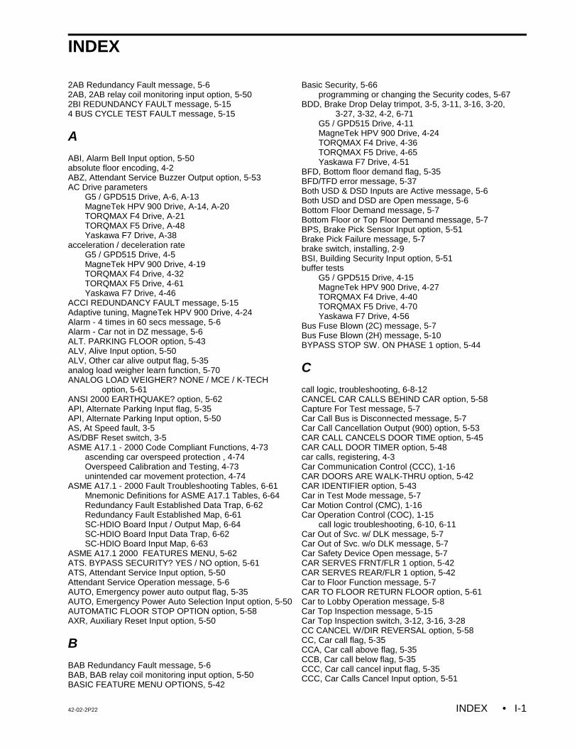
42-02-2P22 INDEX • I-1
INDEX
2AB Redundancy Fault message, 5-62AB, 2AB relay coil monitoring input option, 5-502BI REDUNDANCY FAULT message, 5-154 BUS CYCLE TEST FAULT message, 5-15
A
ABI, Alarm Bell Input option, 5-50absolute floor encoding, 4-2ABZ, Attendant Service Buzzer Output option, 5-53AC Drive parameters
G5 / GPD515 Drive, A-6, A-13MagneTek HPV 900 Drive, A-14, A-20TORQMAX F4 Drive, A-21TORQMAX F5 Drive, A-48Yaskawa F7 Drive, A-38
acceleration / deceleration rateG5 / GPD515 Drive, 4-5MagneTek HPV 900 Drive, 4-19TORQMAX F4 Drive, 4-32TORQMAX F5 Drive, 4-61Yaskawa F7 Drive, 4-46
ACCI REDUNDANCY FAULT message, 5-15Adaptive tuning, MagneTek HPV 900 Drive, 4-24Alarm - 4 times in 60 secs message, 5-6Alarm - Car not in DZ message, 5-6ALT. PARKING FLOOR option, 5-43ALV, Alive Input option, 5-50ALV, Other car alive output flag, 5-35analog load weigher learn function, 5-70ANALOG LOAD WEIGHER? NONE / MCE / K-TECH
option, 5-61ANSI 2000 EARTHQUAKE? option, 5-62API, Alternate Parking Input flag, 5-35API, Alternate Parking Input option, 5-50AS, At Speed fault, 3-5AS/DBF Reset switch, 3-5ASME A17.1 - 2000 Code Compliant Functions, 4-73
ascending car overspeed protection , 4-74Overspeed Calibration and Testing, 4-73unintended car movement protection, 4-74
ASME A17.1 - 2000 Fault Troubleshooting Tables, 6-61Mnemonic Definitions for ASME A17.1 Tables, 6-64Redundancy Fault Established Data Trap, 6-62Redundancy Fault Established Map, 6-61SC-HDIO Board Input / Output Map, 6-64SC-HDIO Board Input Data Trap, 6-62SC-HDIO Board Input Map, 6-63
ASME A17.1 2000 FEATURES MENU, 5-62ATS. BYPASS SECURITY? YES / NO option, 5-61ATS, Attendant Service Input option, 5-50Attendant Service Operation message, 5-6AUTO, Emergency power auto output flag, 5-35AUTO, Emergency Power Auto Selection Input option, 5-50AUTOMATIC FLOOR STOP OPTION option, 5-58AXR, Auxiliary Reset Input option, 5-50
B
BAB Redundancy Fault message, 5-6BAB, BAB relay coil monitoring input option, 5-50BASIC FEATURE MENU OPTIONS, 5-42
Basic Security, 5-66programming or changing the Security codes, 5-67
BDD, Brake Drop Delay trimpot, 3-5, 3-11, 3-16, 3-20, 3-27, 3-32, 4-2, 6-71
G5 / GPD515 Drive, 4-11MagneTek HPV 900 Drive, 4-24TORQMAX F4 Drive, 4-36TORQMAX F5 Drive, 4-65Yaskawa F7 Drive, 4-51
BFD, Bottom floor demand flag, 5-35BFD/TFD error message, 5-37Both USD & DSD Inputs are Active message, 5-6Both USD and DSD are Open message, 5-6Bottom Floor Demand message, 5-7Bottom Floor or Top Floor Demand message, 5-7BPS, Brake Pick Sensor Input option, 5-51Brake Pick Failure message, 5-7brake switch, installing, 2-9BSI, Building Security Input option, 5-51buffer tests
G5 / GPD515 Drive, 4-15MagneTek HPV 900 Drive, 4-27TORQMAX F4 Drive, 4-40TORQMAX F5 Drive, 4-70Yaskawa F7 Drive, 4-56
Bus Fuse Blown (2C) message, 5-7Bus Fuse Blown (2H) message, 5-10BYPASS STOP SW. ON PHASE 1 option, 5-44
C
call logic, troubleshooting, 6-8-12CANCEL CAR CALLS BEHIND CAR option, 5-58Capture For Test message, 5-7Car Call Bus is Disconnected message, 5-7Car Call Cancellation Output (900) option, 5-53CAR CALL CANCELS DOOR TIME option, 5-45CAR CALL DOOR TIMER option, 5-48car calls, registering, 4-3Car Communication Control (CCC), 1-16CAR DOORS ARE WALK-THRU option, 5-42CAR IDENTIFIER option, 5-43Car in Test Mode message, 5-7Car Motion Control (CMC), 1-16Car Operation Control (COC), 1-15
call logic troubleshooting, 6-10, 6-11Car Out of Svc. w/ DLK message, 5-7Car Out of Svc. w/o DLK message, 5-7Car Safety Device Open message, 5-7CAR SERVES FRNT/FLR 1 option, 5-42CAR SERVES REAR/FLR 1 option, 5-42Car to Floor Function message, 5-7CAR TO FLOOR RETURN FLOOR option, 5-61Car to Lobby Operation message, 5-8Car Top Inspection message, 5-15Car Top Inspection switch, 3-12, 3-16, 3-28CC CANCEL W/DIR REVERSAL option, 5-58CC, Car call flag, 5-35CCA, Car call above flag, 5-35CCB, Car call below flag, 5-35CCC, Car call cancel input flag, 5-35CCC, Car Calls Cancel Input option, 5-51
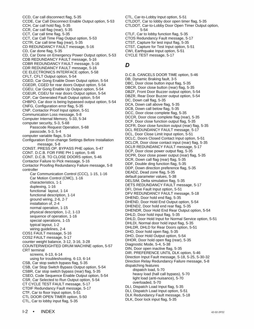
• INDEX 42-02-2P22I-2
CCD, Car call disconnect flag, 5-35CCDE, Car Call Disconnect Enable Output option, 5-53CCH, Car call hold flag, 5-35CCR, Car call flag (rear), 5-35CCT, Car call time flag, 5-35CCT, Car Call Time Flag Output option, 5-53CCTR, Car call time flag (rear), 5-35CD REDUNDANCY FAULT message, 5-16CD, Car done flag, 5-35CD, Car Done on Emergency Power Output option, 5-53CDB REDUNDANCY FAULT message, 5-16CDBR REDUNDANCY FAULT message, 5-16CDR REDUNDANCY FAULT message, 5-16CE ELECTRONICS INTERFACE option, 5-58CFLT, CFLT Output option, 5-54CGED, Car Gong Enable Down Output option, 5-54CGEDR, CGED for rear doors Output option, 5-54CGEU, Car Gong Enable Up Output option, 5-54CGEUR, CGEU for rear doors Output option, 5-54CGF, Car Generated Fault Output option, 5-54CHBPO, Car door is being bypassed output option, 5-54CNFG, Configuration error flag, 5-35CNP, Contactor Proof Input option, 5-51Communication Loss message, 5-8Computer Internal Memory, 5-33, 5-34computer security, 5-3, 5-68
Passcode Request Operation, 5-68passcode, 5-3, 5-4
computer variable flags, 5-34Configuration Error-change Settings Before Installation
message, 5-8CONST. PRESS OP. BYPASS PHE option, 5-47CONT. D.C.B. FOR FIRE PH 1 option, 5-46CONT. D.C.B. TO CLOSE DOORS option, 5-46Contactor Failure to Pick message, 5-16Contactor Proofing Redundancy Failure message, 5-8controller
Car Communication Control (CCC), 1-15, 1-16Car Motion Control (CMC), 1-16characteristics, 1-1duplexing, 1-16functional layout, 1-14functional description, 1-14ground wiring, 2-6, 2-7installation of, 2-4normal operation, 1-15physical description, 1-2, 1-13sequence of operation, 1-16special operations, 1-15typical layout, 1-2wiring guidelines, 2-4
COS1 FAULT message, 5-16COS2 FAULT message, 5-17counter weight balance, 3-12, 3-16, 3-28COUNTERWEIGHTED DRUM MACHINE option, 5-57CRT terminal
screens, 6-13, 6-14using for troubleshooting, 6-13, 6-14
CSB, Car stop switch bypass flag, 5-35CSB, Car Stop Switch Bypass Output option, 5-54CSBR, Car stop switch bypass (rear) flag, 5-35CSEO, Code Sequence Enable Output option, 5-54CSR, Car Selected to Run Output option, 5-54CT CYCLE TEST FAULT message, 5-17CTDIF Redundancy Fault message, 5-17CTF, Car to floor Input option, 5-51CTL DOOR OPEN TIMER option, 5-50CTL, Car to lobby input flag, 5-35
CTL, Car-to-Lobby Input option, 5-51CTLDOT, Car to lobby door open timer flag, 5-35CTLDOT, Car-to-Lobby Door Open Timer Output option,
5-54CTLF, Car to lobby function flag, 5-35CTOS Redundancy Fault message, 5-17CTST, Capture for test input flag, 5-35CTST, Capture for Test Input option, 5-51CWI, Earthquake Input option, 5-51CYCLE TEST message, 5-17
D
D.C.B. CANCELS DOOR TIME option, 5-46DB, Dynamic Braking fault, 3-5DBC, Door close button input flag, 5-35DBCR, Door close button (rear) flag, 5-35DBZF, Front Door Buzzer output option, 5-54DBZR, Rear Door Buzzer output option, 5-54DC, Down call flag, 5-35DCA, Down call above flag, 5-35DCB, Down call below flag, 5-35DCC, Door close complete flag, 5-35DCCR, Door close complete flag (rear), 5-35DCF, Door close function output flag, 5-35DCFR, Door close function output (rear) flag, 5-35DCL REDUNDANCY FAULT message, 5-17DCL, Door Close Limit Input option, 5-51DCLC, Doors Closed Contact Input option, 5-51DCLCR, Door close contact input (rear) flag, 5-35DCLR REDUNDANCY FAULT message, 5-17DCP, Door close power output flag, 5-35DCPR, Door close power output (rear) flag, 5-35DCR, Down call flag (rear) flag, 5-35DDF, Double ding function flag, 5-35DDP, Down direction preference flag, 5-35DEADZ, Dead zone flag, 5-35default parameter values, 5-38DELSIM, Delta simulation flag, 5-35DETS REDUNDANCY FAULT message, 5-17DFI, Drive Fault Input option, 5-51DFV REDUNDANCY FAULT message, 5-18DHEND, Door hold end flag, 5-35DHEND, Door Hold End Output option, 5-54DHEND2, Door hold end rear flag, 5-35DHENDR, Door Hold End Rear Output option, 5-54DHLD, Door hold input flag, 5-35DHLD, Door Hold Input for Normal Service option, 5-51DHLDI, Normal door hold input flag, 5-35DHLDR, DHLD for Rear Doors option, 5-51DHO, Door hold open flag, 5-35DHO, Door Hold Output option, 5-54DHOR, Door hold open flag (rear), 5-35Diagnostic Mode, 5-4, 5-38DIN, Door open inactive flag, 5-35DIR. PREFERENCE UNTIL DLK option, 5-46Direction Input Fault message, 5-18, 5-25, 5-30-32Direction Relay Redundancy Failure message, 5-8dispatching features
dispatch load, 5-70heavy load (hall call bypass), 5-70light load (anti-nuisance), 5-70overloaded, 5-70
DLI, Dispatch Load Input flag, 5-35DLI, Dispatch Load Input option, 5-51DLK Redundancy Fault message, 5-18DLK, Door lock input flag, 5-35
42-02-2P22 INDEX • I-3
DLKS, Door lock store bit flag, 5-35DLOB, Door Left Open Bell Output option, 5-54DLS, Door Lock Sensor Input option, 5-51DLSR, DLS for rear doors option, 5-51DLW, Dispatch load weighing function flag, 5-35DMD, Demand down flag, 5-35DMU, Demand up flag, 5-36DNDIR REDUNDANCY FAULT message, 5-18DNDO, Down direction output flag, 5-36DNI, Down Input (Attendant Service) option, 5-51DNO, Down output (Attendant Service) option, 5-54DNS REDUNDANCY FAULT message, 5-18DNS, Down direction sense input flag, 5-36DO1, DO2, DO4, DO8, DO16, D032
Binary coded P.I. outputs for digital P.I. devices option,5-54
DOB, Door open button input flag, 5-36DOBR, Door open button input (rear) flag, 5-36DOC, Door open command flag, 5-36DOCR, Door open command (rear) flag, 5-36DOF, Door open function output flag, 5-36DOFR, Door open function output (rear) flag, 5-36DOI, Door open intent flag, 5-36DOIR, Door open intent flag (rear), 5-36DOL, Door open limit input flag, 5-36DOLM, Door open limit memory flag, 5-36DOLMR, Door open limit memory flag (rear), 5-36DOLR, Door open limit (rear) flag, 5-36DOOR BUZZER TIMER option, 5-50Door Close Protection message, 5-8Door Close Protection Timer Elapsed message, 5-8DOOR HOLD INPUT TIMER option, 5-49door logic, troubleshooting, 6-3, 6-4DOOR OPEN PROTECTION TIMER option, 5-49DOOR OPERATION MENU OPTIONS, 5-44door operator diode, installing, 2-12Door Position Monitor switch, 2-12Door Sequence of Operation Flowchart, 6-6DOOR TYPE IS? HORIZONTAL / VERTICAL option, 5-48Door Zone Input Fault message, 5-18, 5-19, 5-26Door Zone Sensor Failure - OFF Position message, 5-8DOORS TO LATCH DCF? option, 5-48DOORS TO LATCH DOF? option, 5-48DOORS TO OPEN IF NO DEMAND option, 5-47DOORS TO OPEN IF PARKED option, 5-47DOORS TO OPEN ON ALT FIRE option, 5-47DOORS TO OPEN ON MAIN FIRE option, 5-47DOUBLE STRIKE ON DOWN option, 5-50Down Fast Valve Fault message, 5-18, 5-25DOWN NORMAL LIMIT SWITCH OPEN message, 5-18Down Slow Valve Fault message, 5-26DP Sensor / Differential Fault message, 5-18DPD, Down previous direction flag, 5-36DPM REDUNDANCY FAULT message, 5-19DPM, Front Door Position Monitoring Input, 5-51DPMR REDUNDANCY FAULT message, 5-19DPMR, Rear Door Position Monitoring Input option, 5-51DPR, Door protection timer flag, 5-36drawing numbers, 2-3Drive Failed to Respond message, 5-8DRIVE FAULT / REI REDUNDANCY FAULT message,
5-19Drive Fault message, 5-8DSD, Down slow down input flag, 5-36DSH, Door shortening flag, 5-36DSH, Door Time Shortening Output (intermediate) option,
5-54DSHT, Door shortening flag , 5-36
DSHT, Door Time Shortening Front Output (final) option, 5-54
DSHTR, Door shortening flag (rear), 5-36DSHTR, Door Time Shortening Front Output (rear) option,
5-54DSTI, Door Stop Input option, 5-51DSTIR, DSTI for rear doors option, 5-51duplexing, 1-16, 5-73DZ, Door zone input flag, 5-36DZORDZ, Front or rear door zone input flag, 5-36DZP, Door zone previous flag, 5-36DZR, Door zone input (rear) flag, 5-36DZRX REDUNDANCY FAULT message, 5-19DZX REDUNDANCY FAULT message, 5-19
E
Earthquake - Reduced Speed Operation message, 5-9Earthquake message, 5-8Earthquake Operation message, 5-8EARTHQUAKE OPERATION option, 5-57EBR Button Fault message, 5-19EBR FLICKERING FAULT message, 5-19EBR STUCK FAULT message, 5-19ECC, Excess car calls flag, 5-36ECRN, Emergency Car Freeze Input option, 5-51ECRN, Emergency car run flag, 5-36ECRN, Emergency Power Car Run Output option, 5-54EDS, Earthquake Direction Switch Input option, 5-51EDTLS, Earthquake Direction Terminal Limit Switch option,
5-51EFG, Egress Floor Gong Output option, 5-54EGRESS FLOOR ARRIVAL GONG option, 5-50elevator security, A-27, A-28Elevator Shutdown Switch Active message, 5-9Emer. Terminal Sw. Failure message, 5-17, 5-32Emergency Brake Activated message, 5-20EMERGENCY BRAKE CYCLE TEST FAULT message,
5-20Emergency Medical Service message, 5-9Emergency Power message, 5-9Emergency Power Operation message, 5-9EMERGENCY POWER OPERATION option, 5-56emergency terminal limit switch monitor
G5 / GPD515 Drive, 4-14MagneTek HPV 900 Drive, 4-27TORQMAX F4 Drive, 4-39TORQMAX F5 Drive, 4-69
EMSB, Emergency Medical Service Buzzer Output option,5-54
EMSC, Emergency Medical Switch Car option, 5-51EMSH, Emergency Medical Switch Hall option, 5-52EMSIC, Emergency Medical Service Indicator Car Output
option, 5-54EMSIH, Emergency Medical Service Indicator Hall Output
option, 5-54ENCODE ALL FLOORS option, 5-56End of Run Cycle Test Fault, 5-29End of Run Cycle Test Fault message, 5-17, 5-20, 5-24End of Run Cycle Test Flt message, 5-15Enter Security Code message, 5-9EP1, Emergency Power Phase 1 Output option, 5-54EP2, Emergency Power Phase 2 Output option, 5-54EPI, Emergency power input flag, 5-36EPI, Emergency Power Input option, 5-52EPR, Emergency power return flag, 5-36EPR, Emergency Power Return Input option, 5-52
• INDEX 42-02-2P22I-4
EPRUN, Emergency power run input flag, 5-36EPRUN, Emergency Power Run Input option, 5-52EPSTP, Emergency power stop input flag, 5-36EPSTP, Emergency Power Stop Input option, 5-52EQIND, Earthquake Indicator Output option, 5-54EQR Button Fault message, 5-20EQR FLICKERING FAULT message, 5-20EQR STUCK FAULT message, 5-20Error Status Messages, 5-6ESBYP CYCLE TEST FAULT message, 5-20ESBYP Redundancy Fault message, 5-21ESS, Elevator Shutdown Input option, 5-52ETS Reset switch, 3-5ETS SWITCHES REQUIRED? option, 5-62ETS, Emergency Terminal Limit Overspeed fault, 3-5ETS, Emergency Terminal Limit Speed trimpot, 3-5ETS, Emergency Terminal Limit trimpot, 4-2ETS1 FAULT message, 5-21ETS2 FAULT message, 5-21EXMLT Input Is Activated message, 5-9EXMLT message, 5-9EXMLTC, Complimented EXMLT Input, 5-52External Memory mode, 5-62, 5-66EXTRA FEATURES MENU OPTIONS, 5-56
F
FAN/LIGHT OUTPUT TIMER option, 5-49FCCC, Fire Phase 2 Call Cancel Button Input option, 5-52FCCC, Fire phase 2 car call cancel flag, 5-36FCHLD, Fire phase 2 hold flag, 5-36FCHLD, Fire Phase 2 Switch HOLD Position Input option,
5-52FCOFF, Fire phase 2 off flag, 5-36FCOFF, Fire Phase 2 Switch OFF Position Input option,
5-52FCS, Fire phase 2 input flag, 5-36FCSM, Fire service phase 2 input memory flag, 5-36FDC, Door fully closed phase 2 flag, 5-36FDCR, Door fully closed phase 2 (rear) flag, 5-36field connections, 1-11FIR1, Fire Service Phase I output option, 5-54FIRE BYPASSES HOSPITAL option, 5-60FIRE PHASE 1 ALT. FLOOR option, 5-43FIRE PHASE 1 MAIN FLOOR option, 5-43FIRE PHASE I 2ND ALT. FLOOR option, 5-44Fire Service Alternate message, 5-9Fire Service Main message, 5-9FIRE SERVICE MENU OPTIONS, 5-43FIRE SERVICE OPERATION option, 5-43Fire Service Phase 1 - Main message, 5-9Fire Service Phase 1 -Alternate message, 5-9Fire Service Phase 2 message, 5-9FIRE SVCE. CODE option, 5-44FLASH, Flash output option, 5-54Flex-Talk option, A-29-A-31FLO, Fan/Light Operation Output option, 5-55FLOOR ENCODING INPUTS option, 5-56flux vector applications
G5 / GPD515 Drive, 4-10, 4-12Yaskawa F7 Drive, 4-50, 4-52
FRA, Alternate Fire service phase 1 input flag, 5-36FRAA, Fire Phase 1 Alternate (2nd alternate) Input option,
5-52FRAON, Fire Phase 1 Alternate Switch ON Position Input
option, 5-52FRAS, Alternate fire flag, 5-36
FRBYP, Fire phase 1 bypass input flag, 5-36FRBYP, Fire Phase 1 Switch BYPASS Position Input
option, 5-52FRC, Fire phase 2 flag, 5-36FRC, Fire Service Phase 2 Output option, 5-55FREE, No demand and in service flag, 5-36FRM, Fire service phase 1 flag, 5-36FRM, Fire Service Phase 1 Output option, 5-55FRON, Fire phase 1 on input flag, 5-36FRON, Fire Phase 1 Switch ON Position Input option, 5-52FRON2, Fire Phase 1 Switch ON Position Input option,
5-52Front DOL & DLK are Both Active message, 5-9Front Door Input Fault message, 5-16, 5-17, 5-19, 5-21,
5-25, 5-27Front Door is Locked but not fully closed message, 5-9Front Door Lock Switch Failure message, 5-10FRONT DOOR MECH. COUPLED? option, 5-48Front Door Open Limit Failure message, 5-10Front Gate Switch Failure message, 5-10FRS, Fire phase 1 input flag, 5-36FRSA, Alternate Fire Service input option, 5-52FRSM, Main Fire Service input option, 5-52FRSS, Fire phase 1 flag, 5-36FSA, Fire Service Alternate Output option, 5-55FSM, Fire Service Main Output option, 5-55FSO, Fire Service On Output option, 5-55FSVC, True Fire Service Output option, 5-55FULLY MANUAL DOORS option, 5-46FWI, Fire warning indicator output flag, 5-36FWL, Fire Warning Light Output option, 5-55
G
G5 / GPD515 Driveacceleration / deceleration rates, 4-5alarms and faults, 6-18buffer tests, 4-15critical parameters, 3-6, 3-9drive parameters table, A-6, A-13emergency terminal limit switch monitor, 4-14Final Adjustments, 4-8, 4-13Final Inspection Procedure, 4-13, 4-18flux vector applications, 4-10, 4-12governor overspeed tests, 4-16High speed, 4-9Inspection Leveling Overspeed test, 4-13, 4-26Inspection operation, 3-6, 3-12Inspection Speed, 3-10load testing, 4-12parameter sheets, 3-6phase loss detection test, 4-17running on Normal operation, 4-8, 4-10-12S-curve parameters, 4-6, 4-7setting the speed levels, 4-4terminal slowdown limit switches, 4-14troubleshooting, 6-15-18
GED, Gong enable down output flag, 5-35GEDR, Gong enable down output (rear) flag, 5-35GEU, Gong enable up output flag, 5-35GEUR, Gong enable up output (rear) flag, 5-35GHT, Gong hold timer flag, 5-35GHTR, Gong hold timer flag (rear), 5-35GONGS/LANTERNS MENU OPTIONS, 5-50GOV Redundancy Fault message, 5-21GOV, Governor input option, 5-52
42-02-2P22 INDEX • I-5
governor overspeed testsG5 / GPD515 Drive, 4-16MagneTek HPV 900 Drive, 4-29TORQMAX F4 Drive, 4-42TORQMAX F5 Drive, 4-71Yaskawa F7 Drive, 4-57
Governor Switch Open message, 5-10ground check, 3-1ground wiring, 2-6, 2-7GS, Gate Switch Input option, 5-52GSR, Gate Switch Rear Input option, 5-52GTDE, Gong timer down enable flag, 5-35GTUE, Gong timer up enable flag, 5-35
H
H Redundancy Fault message, 5-21H, High speed output flag, 5-35Hall and Car Call Buses Disconnected message, 5-10Hall Call Bus is disconnected message, 5-10HALL CALL DOOR TIMER option, 5-48HC-ACI AC Drive Interface Board, 1-12, 3-4, 3-15
Quick Reference, 6-71HC-ACIF Additional Flux Vector Drive Interface Board,
1-12, 1-13, 3-5Quick Reference, 6-72
HC-CI/O, Call Input/Output Board, 1-3, 1-4Quick Reference, 6-10troubleshooting, 6-10, 6-11
HC-I4O Input/Output Expander Board, 1-4HC-IOX Input/Output Expander Board, 1-4HC-PCI/O Power and Call Input/Output Board, 1-2, 1-3
Quick Reference, 6-2HC-RB4-VFAC Main Relay Board, 1-10, 3-3HCDX, Hall call disconnect flag, 5-35HCP, Hall call pushed output option, 5-55HCR, Hall call reject flag, 5-35HCR, Hall Call Reject Output option, 5-55HCT, Hall call door time flag, 5-35HCTR, Hall call door time flag (rear), 5-35HD REDUNDANCY FAULT message, 5-21HD, High speed delay flag, 5-35HDB REDUNDANCY FAULT message, 5-21HDBR REDUNDANCY FAULT message, 5-22HDLYE, High speed delay elapsed flag, 5-35HDR REDUNDANCY FAULT message, 5-22HDSC, Heat Detector Shutdown Complete Output option,
5-55HEATD, Heat Detector Input option, 5-52Heavy Load Weigher Condition message, 5-10High speed
G5 / GPD515 Drive, 4-9MagneTek HPV 900 Drive, 4-22TORQMAX F4 Drive, 4-35TORQMAX F5 Drive, 4-64Yaskawa F7 Drive, 4-49
HIGH SPEED DELAY AFTER RUN option, 5-60HLI, Heavy load input flag, 5-35HLI, Heavy Load Input option, 5-52HLW, Heavy load weigher flag, 5-35HLW, Heavy Load Weigher Output option, 5-55HML, Home landing input flag, 5-35HML, Home Landing Input option, 5-52Hoistway Access Input Flt message, 5-15, 5-22Hoistway Access message, 5-22HOISTWAY ACCESS? option, 5-62Hoistway Safety Device Open message, 5-10
HONEYWELL FIRE OPERATION option, 5-44HOSP, Hospital Emergency Operation Input option, 5-52HOSP, In car hospital emergency input flag, 5-35HOSPH2, Hospital emergency phase 2 flag, 5-35HOSPITAL EMERG. OPERATION option, 5-59HOSPITAL EMERG. TIMER option, 5-49Hospital Phase 1 Operation message, 5-10Hospital Phase 2 Operation message, 5-10Hospital Service message, 5-10HSEL, Hospital service select flag, 5-35
I
ILO, Inspection Leveling Overspeed trimpot, 3-5, 4-2, 6-71ILO1 FAULT message, 5-22ILO2 FAULT message, 5-22In Car Inspection message, 5-22In Car Stop Switch Activated message, 5-10IN REDUNDANCY FAULT message, 5-22IN, Inspection or access input flag, 5-35INA, INAX relay coil monitoring input option, 5-52INAX Redundancy Fault message, 5-10INCF, Independent service car call cancel flag, 5-35INCTI REDUNDANCY FAULT message, 5-23IND. BYPASS SECURITY? YES / NO option, 5-61IND, Independent service input flag, 5-35Independent Service message, 5-10Independent Service Operation message, 5-10INDFRC, Independent Service/Fire Service Phase 2 Output
option, 5-55INDN Redundancy Fault message, 5-23INICI REDUNDANCY FAULT message, 5-23INMR REDUNDANCY FAULT message, 5-23Inspection Input Fault, 5-23Inspection Input Fault message, 5-22, 5-23Inspection Leveling Overspeed test
G5 / GPD515 Drive, 4-13, 4-26MagneTek HPV 900 Drive, 4-26TORQMAX F4 Drive, 4-39TORQMAX F5 Drive, 4-68Yaskawa F7 Drive, 4-54
Inspection message, 5-11Inspection Operation message, 5-11INT, Intermediate speed input flag, 5-35INT, Intermediate Speed Input option, 5-52INTERMEDIATE SPEED BETWEEN FLOORS option, 5-61INTERMEDIATE SPEED option, 5-56INUP Redundancy Fault message, 5-23INV. DOOR CLOSE LIMIT? option, 5-48IRCOF, Front Infra Red Cutout input option, 5-52IRCOR, Rear Infra Red Cutout input option, 5-52ISR, In service and ready flag, 5-35ISRT, In Service and Running Output option, 5-55ISRT, In service truly flag, 5-35ISTD/R2, Intermediate step down/absolute floor encoding
#2 flag, 5-35ISTU/R3, Intermediate step up/absolute floor encoding #3
flag, 5-35ISV, In service flag, 5-35ISV, In Service Output option, 5-55IUL, In Use Light output option, 5-55
• INDEX 42-02-2P22I-6
J
jerk parametersMagneTek HPV 900 Drive, 4-19TORQMAX F4 Drive, 4-32TORQMAX F5 Drive, 4-61
K
KCE ENABLE / DISABLE option, 5-61
L
landing systemLS QUTE Enclosure Assembly, A-32LS QUTE Wiring Diagram, A-33LS-QUTE, 1-17LS-STAN, 1-17, 1-18
Landing System Redundancy Failure message, 5-11landing system, installing, 2-11, 2-12LCD display, 5-5, 5-39, 5-40LD, Level down input flag, 5-35LEAVE DOORS OPEN ON CTL option, 5-47LEAVE DOORS OPEN ON EPI, 5-47LEAVE DOORS OPEN ON MGS option, 5-46LEAVE DOORS OPEN ON PTI/ESS option, 5-46LEF, Leveling encounter flag, 5-35Leveling Down message, 5-11Leveling Input is absent message, 5-11LEVELING SENSOR ENABLED/DISABLED option, 5-61Leveling Sensor Failed - OFF Position message, 5-11Leveling Sensor Failed - ON Position message, 5-11Leveling Sensor Failure message, 5-11Leveling up message, 5-11LFP, Lower parking floor flag, 5-35Light Load Weigher Condition message, 5-11LIGHT LOAD WEIGHING option, 5-56limit switches, installing, 2-11LIMITED DOOR RE-OPEN OPTION option, 5-47LLI, Light load input flag, 5-35LLI, Light Load Input option, 5-52LLW, Light Load Weigher Output option, 5-55LLW, Light load weighing function input flag, 5-35load testing
G5 / GPD515 Drive, 4-12MagneTek HPV 900 Drive, 4-25TORQMAX F4 Drive, 4-37, 4-38TORQMAX F5 Drive, 4-66, 4-67Yaskawa F7 Drive, 4-52, 4-53
load weigher learn function, 5-70load weighing system
DLW, Dispatch Load Weigher threshold, 5-69HLW, Heavy Load Weigher threshold, 5-69LLW, Light Load Weigher threshold, 5-69OLW, Over Load Weigher threshold, 5-69OLW2, Over Load 2 Weigher threshold, 5-69setting load thresholds, 5-69
LOBBY DOOR TIMER option, 5-48LOBBY FLOOR option, 5-43Lost DLK During Run message, 5-11LOT, Lobby door time flag, 5-35LOTR, Lobby door time (rear) flag, 5-35Low Oil Switch Input is Activated message, 5-11LS QUTE landing system
Enclosure Assembly, A-32Wiring Diagram, A-33
LSA Movement Failure message, 5-12LSR, Landing System Redundancy Input option, 5-52LU, Level up input flag, 5-35LWB, Load Weigher Bypass input, 5-52
M
MagneTek HPV 900 Driveacceleration / deceleration rates, 4-19alarms and faults, 6-23buffer tests, 4-27critical parameters, 3-13drive parameters table, A-14, A-20emergency terminal limit switch monitor, 4-27Final Adjustments, 4-21, 4-25Final Inspection Procedure, 4-26, 4-30governor overspeed tests, 4-29High speed, 4-22Inspection Leveling Overspeed test, 4-26Inspection operation, 3-13, 3-17Inspection Speed, 3-15jerk parameters, 4-19load testing, 4-25parameter sheets, 3-13phase loss detection test, 4-30S-curve parameters, 4-20, 4-21setting the speed levels, 4-19terminal slowdown limit switches, 4-26troubleshooting, 6-20, 6-22, 6-23
MASS 524 CMR FIRE CODE? option, 5-44MASSACHUSETTS EMS SERVICE option, 5-58MASTER SOFTWARE KEY option, 5-59MC-PA Peripherals Adapter Board, 1-9
Quick Reference, 6-67setting paramerters to default values, 5-38
MC-PCA Main Computer Board, 1-8, 1-15, 5-1-3setting paramerters to default values, 5-38Quick Reference, 6-66
MECHANICAL SAFETY EDGE option, 5-45MG SHUTDOWN OPERATION option, 5-58MGR OUTPUT TIMER option, 5-49MGR, Motor generator run flag, 5-35MGS, Motor Generator Shutdown Input option, 5-52MISV, Mechanically In Service Output option, 5-55MLT data trap, using for troubleshooting, 6-58MLT, Motor Limit Timer Elapsed Output option, 5-55MLT, Motor limit timer flag, 5-35MOMENT. D.C.B TO CLOSE DOORS? option, 5-48MOMENT. D.O.B. DOOR OPENING option, 5-46Motor Limit Timer (anti-stall) Elapsed message, 5-12Motor Limit Timer message, 5-12MOTOR LIMIT TIMER option, 5-49Motor Up to Speed Failure message, 5-23MOUNTED IN HALL OR CAR option, 5-50MPSAF Redundancy Fault message, 5-23
N
NCD, Car Not Done with Emergency Power Return Outputoption, 5-55
NDGBPS, Nudging bypass flag, 5-35NDGBPSR, Nudging bypass flag (rear), 5-35NDGF, Nudging function flag, 5-35NDS, Hall door timer non-shorten flag, 5-35NDSR, Hall door timer non-shorten (rear) flag, 5-35
42-02-2P22 INDEX • I-7
NEW YORK CITY FIRE PHASE 2 AND ANSI 89 option, 5-44
nomenclature, for PC boards, A-24Normal operation
G5 / GPD515 Drive, 4-8, 4-12MagneTek HPV 900 Drive, 4-21, 4-25TORQMAX F4 Drive, 4-33, 4-37TORQMAX F5 Drive, 4-62, 4-67Yaskawa F7 Drive, 4-48, 4-53
Normal Operation message, 5-12NSI, Non-Stop Input (Attendant Service) option, 5-52NUDG, Nudging output flag, 5-35NUDGING DURING FIRE PH. 1 option, 5-45NUDGING DURING FIRE PHASE 2 option, 5-46NUDGING option, 5-44NUDGING OUTPUT/BUZZER ONLY option, 5-46NUDGING TIMER option, 5-49NUDGR, Nudging output (rear) flag, 5-35NUMBER OF AIOX BOARDS option, 5-43NUMBER OF I4O BOARDS option, 5-43NUMBER OF IOX BOARDS option, 5-43NYDS, New York door shortening flag, 5-35
O
OFR, One Floor Run Output option, 5-55OFRP BETWEEN FLRS option, 5-61OFRP, One Floor Run Programmable Output option, 5-55OLW, Overloaded Car Threshold Output option, 5-55options, setting to default values, 5-38Overload Condition message, 5-12overspeed calibration and testing, 4-73
TORQMAX F5 Drive, 4-72Overspeed Fault message, 5-16, 5-17, 5-21, 5-22, 5-24OVL, Overload Input option, 5-52OVL2, Overload 2 Input, 5-52
P
parameters, setting to default values, 5-38PARKING DELAY TIMER option, 5-49PARKING FLOOR option, 5-43PASS REQ, Passcode Request message, 5-3, 5-4passcode, 5-3, 5-4Passcode Request message, 5-12Passcode Request Option, 5-3, 5-4, 5-68PC boards, nomenclature for, A-24PFG ENABLE BUTTON option, 5-50PFG, Passing floor gong output flag, 5-35PFGE, Passing Floor Gong Enable Input option, 5-53PFLT Fault message, 5-24PFLT RELAY DROPPED message, 5-24PH1, Fire Service Phase 1 Return Complete Output option,
5-55PH1, Phase 1 return complete flag, 5-35phase loss detection test
G5 / GPD515 Drive, 4-17MagneTek HPV 900 Drive, 4-30TORQMAX F4 Drive, 4-43Yaskawa F7 Drive, 4-58
PHE, Photo eye input flag, 5-36PHER, Photo eye input (rear) flag, 5-36PHOTO EYE ANTI-NUISANCE option, 5-57Photo Eye Failure message, 5-12
PI OUTPUT TYPE option, 5-56PI TURNED OFF IF NO DEMAND option, 5-59PIC, PI correction flag, 5-36PLD CYCLE TEST FAULT message, 5-24Power Transfer Input Active message, 5-12Power Up Shut Down Due to Earthquake message, 5-12POWERBACK R4 Regenerative Drive, A-34-A-36
description, A-34drive parameters table, A-36parameter adjustments, A-35
POWERBACK R6 Regenerative Drive, A-45-A-47description, A-45drive parameters table, A-47parameter adjustments, A-46
PRE-OPENING option, 5-45PRESSURE SWITCH ACTIVATED message, 5-12PREVENT DCP TIL DOORS CLOSE? option, 5-48PRIFLG, Priority Service Output option, 5-55Program Mode, 5-39, 5-61PSS, Pressure Switch Input, 5-53PTI, Power Transfer Input option, 5-53
R
R2AB, 2AB relay contact redundancy monitoring inputoption, 5-53
R4, Absolute floor encoding #4 flag, 5-36R4, R3, R2, Floor Encoding Input option, 5-53RACC1 REDUNDANCY FAULT message, 5-24RACC2 REDUNDANCY FAULT message, 5-24RBAB, BAB relay contact redundancy monitoring input
option, 5-53RBRK Redundancy Fault message, 5-24RCD REDUNDANCY FAULT message, 5-25RCDR REDUNDANCY FAULT message, 5-25RCT Redundancy Fault message, 5-25RCTIC REDUNDANCY FAULT message, 5-25RDEL1 REDUNDANCY FAULT message, 5-25RDEL2 REDUNDANCY FAULT message, 5-25RDEL3 REDUNDANCY FAULT message, 5-25RDLSR, Rear Hoistway Door Lock Contacts Relay Status
option, 5-53RDN REDUNDANCY FAULT message, 5-25RDSV REDUNDANCY FAULT message, 5-26RDZ REDUNDANCY FAULT message, 5-26RDZR REDUNDANCY FAULT message, 5-26RDZX REDUNDANCY FAULT message, 5-26Rear DOL & DLK are Both Active message, 5-12Rear Door Input Fault message, 5-16, 5-17, 5-19, 5-22,
5-25, 5-26, 5-28Rear Door is Locked but not fully closed message, 5-12Rear Door Lock Switch Failure message, 5-12REAR DOOR MECH. COUPLED? option, 5-48Rear Door Open Limit Failure message, 5-12Rear Gate Switch Failure message, 5-13REAR, Rear door flag, 5-36REB1 REDUNDANCY FAULT message, 5-26REB2 REDUNDANCY FAULT message, 5-26Red. Access Input Fault message, 5-24, 5-26, 5-30Red. Emergency Brake Fault message, 5-26Red. Inspection Input Fault message, 5-25, 5-26, 5-28REDUCE HCT WITH PHOTO EYE option, 5-47Redundancy Door Lock Relay Failure message, 5-13Redundancy Front Gate Switch Failure message, 5-13Redundancy Rear Gate Switch Failure message, 5-13
• INDEX 42-02-2P22I-8
Regenerative Drivedescription, A-34, A-45drive parameters quick reference, A-36, A-47drive parameters table, A-36, A-47parameter adjustments, A-35, A-46POWERBACK R4, A-34-A-36POWERBACK R6, A-45
REI Redundancy Fault message, 5-19, 5-27REL, Releveling flag, 5-36REO, Re-Open Input option, 5-53RESBYP Redundancy Fault message, 5-27RETIRING CAM OPTION option, 5-45RFR BUTTON FAULT, 5-27RFR Button Fault message, 5-27RFR FLICKERING FAULT message, 5-27RFR STUCK FAULT message, 5-27RGS, Gate Switch Relay Redundancy option, 5-53RGSR, Gate Switch Relay Redundancy Rear Input option,
5-53RH REDUNDANCY FAULT message, 5-27RHD REDUNDANCY FAULT message, 5-27RHDB REDUNDANCY FAULT message, 5-27RHDBR REDUNDANCY FAULT message, 5-28RHDR REDUNDANCY FAULT message, 5-28RIN1 REDUNDANCY FAULT message, 5-28RIN2 REDUNDANCY FAULT message, 5-28RINAX, INAX relay contact redundancy monitoring input
option, 5-53RLULD Redundancy Fault message, 5-28RM1 Redundancy Fault message, 5-28RM2 Redundancy Fault message, 5-28RM3 Redundancy Fault message, 5-28RMR Redundancy Fault message, 5-28ROFRT Redundancy Fault message, 5-29RPLT Redundancy Fault message, 5-29RPM Redundancy Fault message, 5-29RPT Redundancy Fault message, 5-29RSAFM Redundancy Fault message, 5-29RSAFM, SAFM relay contact redundancy monitoring input
option, 5-53RSAFR Cycle Test Fault message, 5-29RSAFR Redundancy Fault message, 5-29RSTOP Redundancy Fault message, 5-30RSYNC Redundancy Fault message, 5-30RTBAB REDUNDANCY FAULT message, 5-30RUDX1 REDUNDANCY FAULT message, 5-30RUDX2 REDUNDANCY FAULT message, 5-30RUDX3 REDUNDANCY FAULT message, 5-30RUDX4 REDUNDANCY FAULT message, 5-30RUFV Redundancy Fault message, 5-30Run Pump Motor Fault message, 5-29RUN, Run flag, 5-36RUP REDUNDANCY FAULT message, 5-31RUSV Redundancy Fault message, 5-31RWYE1 REDUNDANCY FAULT message, 5-31RWYE2 REDUNDANCY FAULT message, 5-31RWYE3 REDUNDANCY FAULT message, 5-31
S
S-curve parametersG5 / GPD515 Drive, 4-6, 4-7MagneTek HPV 900 Drive, 4-20, 4-21TORQMAX F4 Drive, 4-33TORQMAX F5 Drive, 4-62Yaskawa F7 Drive, 4-46, 4-47
SAB, Sabbath input flag, 5-36
SAB, Sabbath Operation Input option, 5-53Sabbath Operation Active message, 5-13SABBATH OPERATION option, 5-60SAFC Redundancy Fault message, 5-31SAFC, Car Safety Input option, 5-53Safety Circuit is Open message, 5-13Safety String Open message, 5-13SAFH Redundancy Fault message, 5-31SAFH, Hoistway Safety Input option, 5-53SC-BASE, Lock Bypass, Access, Overspeed, Emergency
Brake Board, 1-2, 1-5, 1-15Quick Reference, 6-69
SC-BASER Board, 1-6Quick Reference, 6-70
SC-HDIO High Density Input/Output Board, 1-2, 1-7, 1-15SC-SB2K Main Safety Relay Board, 1-10, 1-15
Quick Reference, 6-68SCE, Stepping correction enable flag, 5-36SCROLLING SPEED (SLOW / NORMAL / FAST) option,
5-61SD, Supervisory down flag, 5-36SDA, Down direction arrow flag, 5-36SDT, Short door time flag, 5-36SDTR, Short door time flag (rear), 5-36SE, Safety edge input flag, 5-36SE, Safety Edge Input option, 5-53SEC, Security Code Incorrect Output option, 5-55SECONDARY PARKING FLOOR option, 5-43Selective Collective option, 5-42sequence of operation, 1-16SEQUENTIAL DOOR OPER. (F/R) option, 5-45SER, Safety edge input (rear) flag, 5-36setting parameters to default values, 5-38SHORT DOOR TIMER option, 5-48Shutdown Operation message, 5-13SIMP, Simplex Input option, 5-53SIMPLEX OR DUPLEX option, 5-42SIMPO, Simplex Output option, 5-55Single Automatic Pushbutton option, 5-42Single Button Collective option, 5-42SINGLE SPEED A.C. OPTION option, 5-60SLV, Stable slave flag, 5-36SPARE INPUTS MENU OPTIONS, 5-50SPARE OUTPUTS MENU OPTIONS, 5-53SPD, Speed Pick Delay trimpot, 3-4, 3-11, 3-15, 3-20, 3-27,
3-32, 4-1, 6-71G5 / GPD515 Drive, 4-9MagneTek HPV 900 Drive, 4-22, 4-23TORQMAX F4 Drive, 4-35, 4-36TORQMAX F5 Drive, 4-64, 4-65Yaskawa F7 Drive, 4-49
speed level parametersG5 / GPD515 Drive, 4-4MagneTek HPV 900 Drive, 4-19TORQMAX F4 Drive, 4-31TORQMAX F5 Drive, 4-60Yaskawa F7 Drive, 4-44
speed sensor, installing, 2-8Starter #1 Fault message, 5-25, 5-31Starter #2 Fault message, 5-25, 5-31Starter #3 Fault message, 5-25, 5-31Starter Fault Relay Dropped message, 5-31STARTIN, Start Input option, 5-53Status Displays
Current Load, 5-3Eligibility Map, 5-3PTHC Software Version, 5-3
Status Indicators, 5-1
42-02-2P22 INDEX • I-9
STC, Stepping complete flag, 5-36STD/R0, Step down input/absolute floor encoding #0 flag,
5-36Stop SW/Safety Relay Ckt message, 5-10STOP, In-car Stop Switch Safety Input option, 5-53STU/R1, Step up input/absolute floor encoding #1 flag,
5-36Stuck Door Zone Input message, 5-8Stuck Leveling Input message, 5-11STUCK PHOTO EYE PROTECTION option, 5-45SU, Supervisory up flag, 5-36SUA, Up direction arrow flag, 5-36Synchronization Operation message, 5-13System Mode, 5-66, 5-68System Out of Service message, 5-13
T
TEMPB, Temporary bit flag, 5-36terminal slowdown limit switches
G5 / GPD515 Drive, 4-14MagneTek HPV 900 Drive, 4-26TORQMAX F4 Drive, 4-39TORQMAX F5 Drive, 4-69
Test mode, 4-3, 4-4TEST Redundancy Fault message, 5-31TEST, Test switch input flag, 5-36TEST, Test Switch Input option, 5-53TFA, Timing function active flag, 5-36TFAR, Timing function active (rear) flag, 5-36TFD, Top floor demand flag, 5-36Time Out of Service message, 5-13TIME OUT OF SVCE. TIMER option, 5-49TIMER MENU OPTIONS, 5-48TM switch, installing, 2-12Top Floor Demand message, 5-7TOP LANDING SERVED option, 5-42TORQMAX Drive
drive parameters table, A-21TORQMAX F4 Drive
acceleration / deceleration rates, 4-32alarms and faults, 6-28Brake does not pick - troubleshooting flowchart, 6-34buffer tests, 4-40Car does not move - troubleshooting flowchart, 6-35Critical Drive Parameters - troubleshooting flowchart,
6-31critical parameters, 3-17Drive Key Pad flowchart, 6-30E.LC fault - troubleshooting flowchart, 6-37emergency terminal limit switch monitor, 4-39Encoder fault - troubleshooting flowchart, 6-36Excessive motor noise - troubleshooting flowchart,
6-38Final Adjustments, 4-33, 4-37Final Inspection Procedure, 4-38, 4-43governor overspeed tests, 4-42High speed, 4-35Inspection Leveling Overspeed test, 4-39Inspection operation, 3-17, 3-21Inspection Speed, 3-19jerk parameters, 4-32load testing, 4-37, 4-38parameter sheets, 3-17phase loss detection test, 4-43PM Contactor does not pick - troubleshooting
flowchart, 6-32
S-curve parameters, 4-33setting the speed levels, 4-31terminal slowdown limit switches, 4-39troubleshooting, 6-24-27
TORQMAX F5 Driveacceleration / deceleration rates, 4-61alarms and faults, 6-48buffer tests, 4-70Car does not move - troubleshooting flowchart, 6-53,
6-54Critical Drive Parameters - troubleshooting flowchart,
6-50critical parameters, 3-29Drive Key Pad flowchart, 6-49drive parameters table, A-48E.LC fault - troubleshooting flowchart, 6-56emergency terminal limit switch monitor, 4-69Encoder fault - troubleshooting flowchart, 6-55Excessive motor noise - troubleshooting flowchart, 6-
57Final Adjustments, 4-62, 4-67Final Inspection Procedure, 4-68, 4-73governor overspeed tests, 4-71High speed, 4-64Inspection Leveling Overspeed test, 4-68Inspection operation, 3-29, 3-33Inspection Speed, 3-31jerk parameters, 4-61load testing, 4-66, 4-67parameter sheets, 3-29phase loss detection test, 4-72PM Contactor does not pick - troubleshooting
flowchart, 6-51S-curve parameters, 4-62setting the speed levels, 4-60terminal slowdown limit switches, 4-69troubleshooting, 6-44-47
TOS, Time Out of Service Output option, 5-55TOS, Timed out of service flag, 5-36Traction Motor Limit Timer Logic flowchart, 6-60Troubleshooting
Brake does not pick- TORQMAX F4 drive, 6-34Brake does not pick- TORQMAX F5 drive, 6-53call logic, 6-8-12Car does not move- TORQMAX F4 drive, 6-35Car does not move- TORQMAX F5 drive, 6-54Car Operation Control (COC), 6-10, 6-11Critical Drive Parameters - TORQMAX F4 drive, 6-31Critical Drive Parameters - TORQMAX F5 drive, 6-50door logic, 6-3, 6-4Door Sequence of Operation, 6-6duplexing, 5-74E.LC fault- TORQMAX F4 drive, 6-37E.LC fault- TORQMAX F5 drive, 6-56Encoder fault- TORQMAX F4 drive, 6-36Encoder fault- TORQMAX F5 drive, 6-55Excessive motor noise- TORQMAX F4 drive, 6-38Excessive motor noise- TORQMAX F5 drive, 6-57External Memory mode, 5-63G5 / GPD515 Drive, 6-15-18HC-ACI AC Drive Interface Board Quick Reference,
6-71HC-ACIF Board Quick Reference, 6-72HC-CI/O, Call Input/Output Board, 6-10HC-PCI/O Input Output Board, 6-2MagneTek HPV 900 Drive, 6-20, 6-22, 6-23MC-PA-2K Board Quick Reference, 6-67MC-PCA-OA2K Board Quick Reference, 6-66
• INDEX 42-02-2P22I-10
PM Contactor does not pick- TORQMAX F4 drive, 6-32PM Contactor does not pick- TORQMAX F5 drive, 6-51SC-BASE Board Quick Reference, 6-69SC-BASER Board Quick Reference, 6-70TORQMAX Drive, 6-25TORQMAX F4 Drive, 6-24, 6-27TORQMAX F5 Drive, 6-44, 6-45, 6-47tracing signals, 6-1Traction Motor Limit Timer Logic, 6-60using computer internal memory, 5-34using the CRT terminal, 6-13, 6-14using the MLT Data Trap, 6-58Yaskawa F7 Drive, 6-39-43
U
UC, Up call flag, 5-36UCA, Up call above flag, 5-36UCR, Up call flag (rear), 5-36UDF, Up and Down Direction Relay Fault Input option, 5-53UDP, Up direction preference flag, 5-36UETS REDUNDANCY FAULT message, 5-32UFP, Upper parking floor flag, 5-36UFQ, Up first qualifier flag, 5-36UFV Redundancy Fault message, 5-32UNL REDUNDANCY FAULT message, 5-32Up Fast Valve Fault message, 5-30, 5-32UP NORMAL LIMIT SWITCH OPEN message, 5-32UPD, Up previous direction flag, 5-36UPDIR REDUNDANCY FAULT message, 5-32UPDO, Up direction output flag, 5-36UPI, Up Input (Attendant Service), 5-53UPO, Up Output (Attendant Service) option, 5-55UPS REDUNDANCY FAULT message, 5-32UPS, Up direction sense input flag, 5-36USD, Up slow down input flag, 5-36UTS Redundancy Fault message, 5-32
V
Valve Limit Timer (Anti-stall) Elapsed message, 5-13Valve Limit Timer message, 5-13Viscosity Control Function message, 5-13
W
WHITE PLAINS, NY FIRE CODE option, 5-44wiring
controller wiring, 2-4drawing numbers, 2-3ground wiring, 2-6, 2-7
WLD, Emergency Dispatch Input option, 5-53WLDI, Wildop Indication Output option, 5-55
X
XPI1-XPI7, Auxiliary Position Indicators 1 thru 7 outputoption, 5-55
XSDA, Auxiliary Supervisory Down Arrow output option, 5-56
XUSA, Auxiliary Supervisory Up Arrow output option, 5-56
Y
Yaskawa F7 Driveacceleration / deceleration rates, 4-46alarms and faults, 6-43buffer tests, 4-56critical parameters, 3-22, 3-25drive parameters table, A-38Final Adjustments, 4-48, 4-53Final Inspection Procedure, 4-54flux vector applications, 4-50, 4-52governor overspeed tests, 4-57High speed, 4-49Inspection Leveling Overspeed test, 4-54Inspection operation, 3-22, 3-28Inspection Speed, 3-26load testing, 4-52, 4-53parameter sheets, 3-22phase loss detection test, 4-58running on Normal operation, 4-48-50, 4-52, 4-53S-curve parameters, 4-46, 4-47setting the speed levels, 4-44troubleshooting, 6-39-43
YSIM, Wye simulation bit flag, 5-36
Z
ZADJ, Zero Adjust Output option, 5-56