controlling respirable dust on longwall mining … longwall dust control... · controlling...
TRANSCRIPT

Controlling
Respirable Dust on
Longwall Mining
Operations
Jim Rider
Lead Research Scientist
Dust, Ventilation and Toxic Substance Branch

Sound Practices to Control Respirable
Dust on Longwall Mining Operations
Statistics and Quantifying Dust Levels
Dust Control Philosophy
Dust Control Principles
Controlling Shearer Dust
Controlling Shield Dust
Stageloader/Crusher Dust Control
Dust Control in the Headgate Entry
Controlling Dust On Intake Roadways
Controlling Dust from the Belt Entry
Laboratory Assessment – Tailgate Manifold
On Going Research – Water Curtain / Shield Sprays
Summary - Guidelines

Longwall Statistics
2008 – 179.2 million tons
2013 – 185.0 million tons
53 % of underground production
Working Faces
1994 – 80
2008 – 46
2013 – 48
Average Shift Production
1994 – 3,600 tons per shift
2008 – 5,500 tons per shift
2012 – 6,000 tons per shift
Panel Widths
2002 - 940 ft.
2007 - 967 ft.
2013 - 1,188 ft.
Panel Lengths
2002 - 10,000 ft.
2007 - 10,132 ft.
2013 - 11,307 ft.
Average Cutting Height
2013 - 91 inches

MSHA Inspector Samples Exceeding
Reduced 1.5 mg/m3 PEL, 2000 – 2012
0.0%
5.0%
10.0%
15.0%
20.0%
25.0%
30.0%
35.0%
40.0%
2000 2001 2002 2003 2004 2005 2006 2007 2008 2009 2010 2011 2012
Sam
ple
s Ex
cee
din
g R
edu
ced
PEL
040 Headgate Operator
041 Jack Setter (Longwall)
044 Longwall Operator (Tailgate Side)
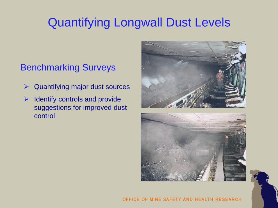
Quantifying Longwall Dust Levels
Benchmarking Surveys
Quantifying major dust sources
Identify controls and provide
suggestions for improved dust
control
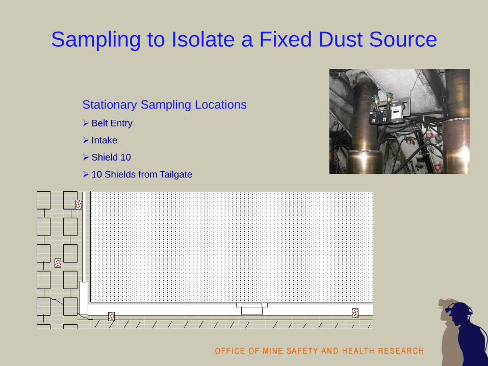
Sampling to Isolate a Fixed Dust Source
x
Stationary Sampling Locations
Belt Entry
Intake
Shield 10
10 Shields from Tailgate

Sampling to Isolate a Mobile Dust Source
Outby Shield Movement (H to T)
Upwind – 3-5 shields upwind of headgate
drum
Shearer – Between mid-shearer and tailgate
drum
Downwind - 3-5 shields downwind of tailgate
drum
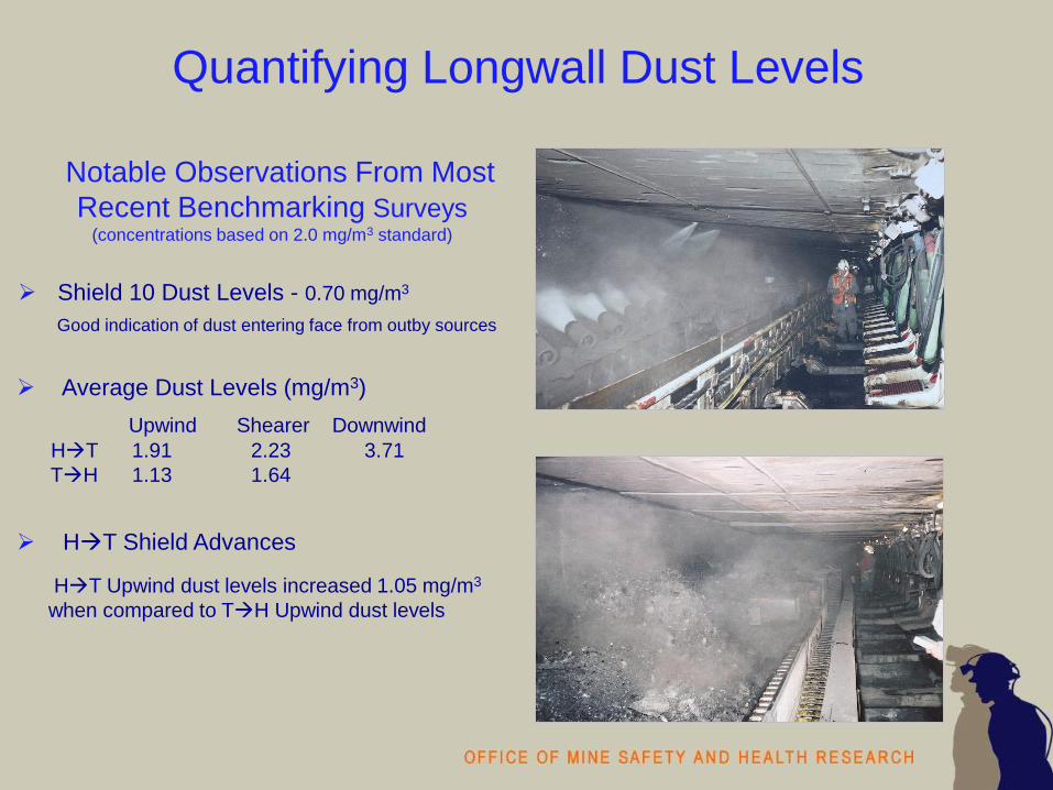
Quantifying Longwall Dust Levels
Notable Observations From Most
Recent Benchmarking Surveys
(concentrations based on 2.0 mg/m3 standard)
Shield 10 Dust Levels - 0.70 mg/m3
Good indication of dust entering face from outby sources
Average Dust Levels (mg/m3)
Upwind Shearer Downwind
HT 1.91 2.23 3.71
TH 1.13 1.64
HT Shield Advances
HT Upwind dust levels increased 1.05 mg/m3
when compared to TH Upwind dust levels

Dust Control Philosophy
Minimize the quantity of respirable dust generated
• efficient cutting
Prevent the respirable dust from getting airborne
• wet dust at generation point
• enclose dust source
Remove respirable dust from ventilating air
• flooded-bed scrubbers and dry dust collectors
• water sprays
Dilute remaining airborne dust
• ventilation quantity
Prevent respirable dust from reaching workers’ breathing zone
• ventilation velocity
• water sprays to move air
• physical barriers

Dust Control Principles
Dilution (quantity)
Transport or Move (velocity)
Ventilation Air
Suppress ( high flow ; low pressure)
Capture (type of spray ; velocity)
Redirect ( high pressure ; spray location)
Water Sprays
Impact of Water on Dust
Suppression – prevent generation
Capture – remove from air (water or mechanical means)
Redirection – directed away from worker
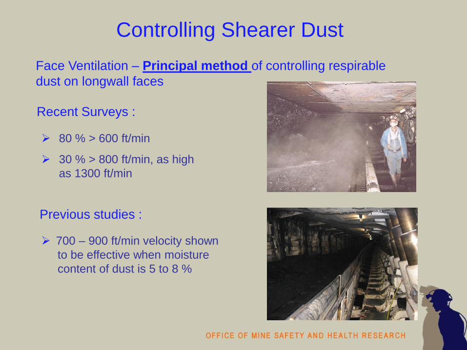
Controlling Shearer Dust
Face Ventilation – Principal method of controlling respirable
dust on longwall faces
80 % > 600 ft/min
30 % > 800 ft/min, as high
as 1300 ft/min
Previous studies :
Recent Surveys :
700 – 900 ft/min velocity shown
to be effective when moisture
content of dust is 5 to 8 %

Controlling Shearer Dust
Dust suppression directly at the
point of coal fracture
Adds moisture to minimize dust
liberation
Full cone or solid stream spray
pattern
Larger orifices increase water
quantity while decreasing pressure
Observed spray pressure ranged
between 100 – 160 psi
Number of sprays per drum
ranged between 35 - 62
Drum Mounted Water Sprays
Full cone
Solid stream

Controlling Shearer Dust
Replacing damaged, worn or
missing bits can not be over emphasized
Dull bits result in shallow cutting and greatly
increases dust generation
Minimize Dust Generation
Maintenance is Critical

Controlling Shearer Dust
Located on the top and end of ranging arms
Sprays oriented toward face
Observed on 50% of recently survey longwalls
Flat fan sprays
Crescent Sprays
Flat fan

Controlling Shearer Dust
Use caution if sprays are utilized
on the headgate ranging arm
Sprays on the end of ranging arm
are oriented into the face airflow
Can create turbulence that force
dust toward the walkway
Crescent Sprays

Controlling Shearer Dust
Headgate Splitter Arm • Headgate arm designed to split the face airflow at the shearer
• Splitter arm sprays induce airflow movement toward face
• Belting on splitter arm provides physical barrier to confine dust
Directional spray system (shearer clearer spray system)
Splitter arm
Shearer mounted sprays oriented downwind
Tailgate splitter arm or spray manifold
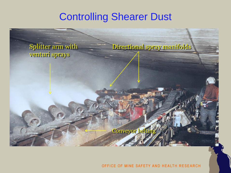
Controlling Shearer Dust
Splitter arm with venturi sprays
Directional spray manifolds
Conveyor belting

Controlling Shearer Dust
Extend as far beyond the headgate drum as possible
Sufficient number of sprays to prevent dust from migrating into walkway
Hollow cone or venturi sprays
Water pressure of at least 150 psi
Maintain proper arm position
Headgate Splitter Arm

Controlling Shearer Dust
Unique to each mine operation
Length – 5 to 14 ft.
3 – 20 sprays
2 splitter arms utilized venturi sprays
Spray orientation • Perpendicular
• 30 - 45 degrees toward panline
• 30 – 45 degrees up
Splitter Arms

Controlling Shearer Dust
Built to withstand coal and rock
impact from face spalls
Splitter arm extensions oriented
at a 30 - 45 degrees toward face
• Length – 2 to 4 ft.
• 3 – 5 sprays
Splitter Arms
Splitter Arm Belting
Belting should be suspended the
length of the splitter arm
Provides a physical barrier

Controlling Shearer Dust
Tears and gaps in the conveyor belting greatly compromise the
effectiveness of the splitter arm
Splitter Arm Belting
Controlling Shearer Dust
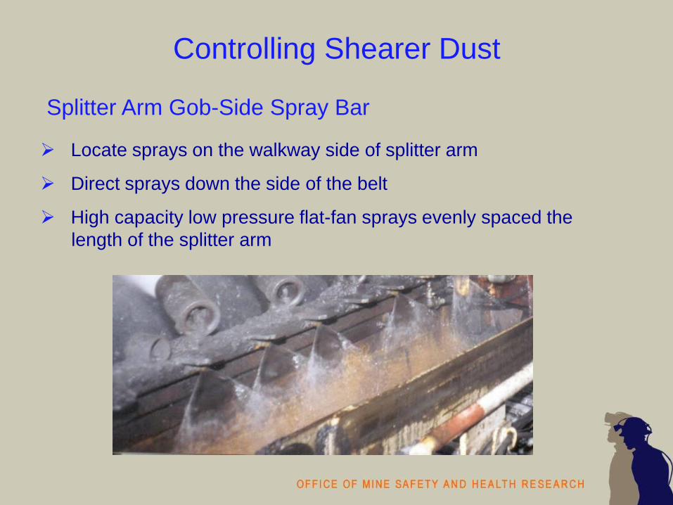
Locate sprays on the walkway side of splitter arm
Direct sprays down the side of the belt
High capacity low pressure flat-fan sprays evenly spaced the
length of the splitter arm
Splitter Arm Gob-Side Spray Bar

Controlling Shearer Dust
Locate sprays on underside
of the splitter arm
Direct sprays down the face
side of the belt
Reduce dust rolling under or
through the splitter arm
Adds more water to the coal
to reduce conveyor dust
Because of turbulence in the
area spray pressure is critical
Splitter Arm Underside Sprays
Controlling Shearer Dust
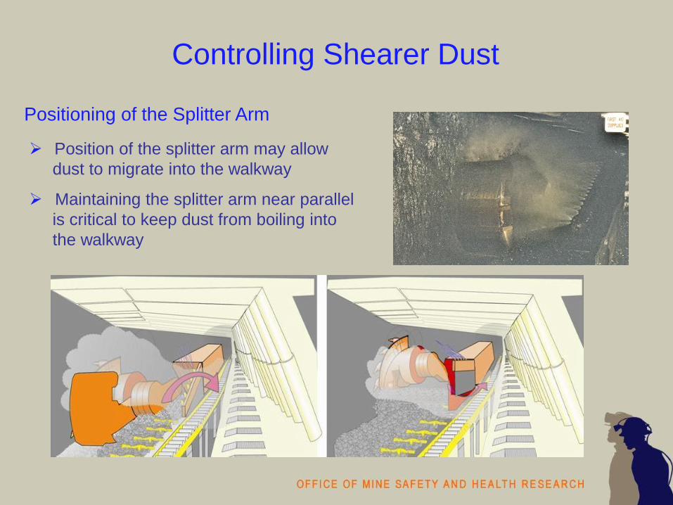
Position of the splitter arm may allow
dust to migrate into the walkway
Maintaining the splitter arm near parallel
is critical to keep dust from boiling into
the walkway
Positioning of the Splitter Arm

Controlling Shearer Dust
Sprays confine dust near face and assist
in moving along shearer body
3 or 4 manifolds evenly spaced
along the length of the shearer
3 to 5 sprays per manifold
Manifolds located on top deck of shearer
or on face side of shearer body
Shearer-body Sprays

Controlling Shearer Dust
Observed at western mines
Primary function is to protect
operators from flying debris
Provide a physical barrier that
can enhance the effectiveness
of the directional spray system
Equipped with water sprays
• Evenly spaced the length
of the deflector plate
Deflector Plates

Controlling Shearer Dust
If sprays operational, spray plume is
directed upward, strikes the underside
of the shields creating turbulence
Potentially allowing dust to migrate into
the walkway
Operators have to be diligent in turning
off the sprays when in the down position
Deflector Plates

Controlling Shearer Dust
Spray manifold mounted on
tailgate end of shearer
Oriented parallel to ranging
arm and angled slightly toward
drum
Confines dust-laden air to face
and carries it beyond the
tailgate drum
Tailgate Side Sprays

Controlling Shield Dust
Automated and usually are initiated within 3-5 shields of trailing drum
Can be a significant source of dust exposure when shields are
advanced upwind of shearer
Concerted effort to rotate jacksetter operators outby
0.000
1.000
2.000
3.000
4.000
5.000
6.000
7.000
8.000
9.000
10.000
09:2
0:0
4
09:2
1:2
4
09:2
2:4
4
09:2
4:0
4
09:2
5:2
4
09:2
6:4
4
09:2
8:0
4
09:2
9:2
4
09:3
0:4
4
09:3
2:0
4
09:3
3:2
4
09:3
4:4
4
09:3
6:0
4
09:3
7:2
4
09:3
8:4
4
09:4
0:0
4
09:4
1:2
4
09:4
2:4
4
09:4
4:0
4
09:4
5:2
4
09:4
6:4
4
09:4
8:0
4
Time
Adju
ste
d P
DR
Concentr
atio
n (
mg/m
3)
OUTBY SHIELD MOVEMENT
UPWIND of HEADGATE DRUM
MID-SHEARER
DOWNWIND of TAILGATE DRUM

Controlling Shield Dust
Traditional canopy-mounted sprays
• Discharge water on top of shields
• Hard to maintain sprays
• Effectiveness not quantified
Dilution
• Higher face air quantities can
increase dilution of shield dust
• Higher velocities have the potential to
entrain more shield dust because the
dust is typically dry
• Advance shields as far upwind as
possible on head-to-tail passes to
allow dilution
Depending on roof conditions consider
using uni-directional cutting sequence

Controlling Shield Dust
Automatically activated by shearer
to create a moving water curtain
1 or 2 rows of sprays per shield
Located between the tip of the shield to
an area above the spill plate
Spray activation and de-activation
sequencing was mine specific
Proper sequencing is critical
Observed shield sprays interacting with
splitter arm sprays creating turbulence
Dust and mist cloud rolled into walkway
Shield Sprays on the Underside of the Canopy

Stageloader/Crusher Dust Control
Stageloader/crusher are fully enclosed
No universally applied technique
Combination of steel plates
Conveyor belting at entrance and
discharge area
Imperative that seals and skirts be
maintained
Scrubbers

Stageloader/Crusher Dust Control
Typical spray locations
• Entrance
• Above crusher hammer
• Discharge area
• Belt transfer area
Spray bar spans the width
3-4 full cone sprays
Water quantity over pressure
Water pressure <= 60 psi
Crusher and Belt Transfer Sprays

Stageloader/Crusher Dust Control
Scrubbers
Crusher discharge
Belt transfer area
Capacity – 6500 – 8500 ft3/min
Potential to create negative
pressure in the stageloader/crusher
to minimize dust from leaking out

Dust Control in the Headgate Entry
Installation and maintenance of a gob curtain

Dust Control in the Headgate Entry
Installation of a wing or cut-out curtain between and
panel-side rib and the stageloader

Dust Control in the Headgate Entry
Position face personnel outby as headgate drum cuts
out into headgate entry
Location of face workers • Drum is exposed to the primary
airstream
• Dust levels as high as 20.0 –
30.0 mg/m3 for a short duration
• Position face personnel near
shields 1 and 2 and further outby
• Concerted effort to move outby
cutout area

Dust Control in the Headgate Entry
Deflection barriers in headgate area
Location of deflection barriers
• Belting attached to underside
of shields 1-4
• Belting attached to top of
conveyor drive
• Aids in turning air down the face
• Protects face personnel from
flying rock
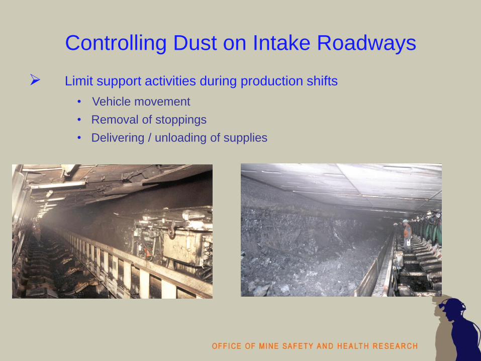
Controlling Dust on Intake Roadways
Limit support activities during production shifts
• Vehicle movement
• Removal of stoppings
• Delivering / unloading of supplies

Controlling Dust on Intake Roadways
Water Application
• Maintain moisture content at approximately 10 %
• Operators must diligent in monitoring moisture content
Salts
• Apply calcium and magnesium
chloride to increase surface moisture
Utilize Surfactants
• Beneficial in maintaining proper moisture content
• Decrease surface tension
• More uniform wetting of the dust
particles

Controlling Dust from the Belt Entry
Wetting of the Coal Product - With the substantial increase in
airflow rewetting of the coal may be necessary along the belt
• Flat or full cone sprays
• Quantity over Pressure
• Pressure - 50 - 60 psi
Full cone Flat fan

Controlling Dust from the Belt Entry
Belt Maintenance - Missing rollers, belt slippage, and
worn belts can cause belt misalignment and create spillage

Controlling Dust from the Belt Entry
Wetting of the Belt
• Full cone spray on top surface of
non-conveying side belt followed
by material to wipe belt and
remove dust fines
Rotary Brush
• Clean the conveying side of the
belt

Laboratory Assessment
Tailgate-side Shearer Spray Manifold
Face Velocity - 500, 700, 900 fpm
Spray Pressure - 100, 150, 200 psi
Spray Manifold – 4” x 36”
• SS BD3 Hollow Cone – 7 sprays
• 42” from TG drum – 25 degree angle
toward the face
Spray Manifold – 4” x 36”
• SS 40-20 Flat fan Spray – 2 sprays
• 47” from TG drum – 15 degree angle
toward the face
Spray Manifold - 2 manifolds – 4” x 36”
• SS 65-15 Flat fan Spray – 2 sprays
• 32” and 37” from TG drum – parallel to
face

Laboratory Assessment
Tailgate-side Shearer Spray Manifold
All spray nozzles substantially reduced
dust under all test conditions.
Reductions in dust concentrations ranged
between 60% and 95%.
Flat fan sprays compared to the hollow
cones sprays were more effective at
reducing dust concentrations.
No apparent relation between air velocity
and reduced dust concentration for any of
the nozzle types.

Tailgate-side Shearer Spray Manifold Gravimetric Dust Concentrations
Velocity 500 fpm Velocity 900 fpm
2 Manifolds and 4 SS 65-15 Flat Fan Sprays Sp
ray
Pres
sure
200
psi
Spra
y Pr
essu
re 1
00 p
si
Sprays Off (mg/m3) Sprays On (mg/m3)
0
5
10
15
20
25
30
35
15 16 17 18 19 20
0.0
5.0
10.0
15.0
20.0
25.0
30.0
35.0
15 16 17 18 19 20
0
5
10
15
20
25
30
35
15 16 17 18 19 20
0.0
5.0
10.0
15.0
20.0
25.0
30.0
35.0
15 16 17 18 19 20

Tailgate-side Shearer Spray Manifold Instantaneous (pDR) Dust Concentrations
SHIELD 15 SHIELD 16 SHIELD 17 SHIELD 18 SHIELD 19 SHIELD 20 RETURN
Velocity 500 fpm Velocity 900 fpm
2 SS 40-20 Flat Fan Sprays
Spra
y Pr
essu
re 2
00 p
siSp
ray
Pres
sure
100
psi
0.0
5.0
10.0
15.0
20.0
25.0
30.0
35.0
00:00 10:00 20:00 10:00 20:00 10:00 20:00
0.0
5.0
10.0
15.0
20.0
25.0
30.0
35.0
00:00 10:00 20:00 10:00 20:00 10:00 20:000.0
5.0
10.0
15.0
20.0
25.0
30.0
35.0
00:00 10:00 20:00 10:00 20:00 10:00 20:00
0.0
5.0
10.0
15.0
20.0
25.0
30.0
35.0
00:00 10:00 20:00 10:00 20:00 10:00 20:00
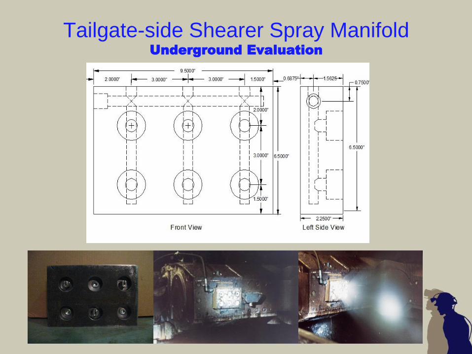
Tailgate-side Shearer Spray Manifold Underground Evaluation

Tailgate-side Shearer Spray Manifold Underground Evaluation
Face velocity (approximately 1300 fpm) was the dominating
dust control factor resulting in very low dust levels at the
sampling locations.
Dust levels observed with gravimetric samplers : 0.856 mg/m3
(SHEARER) ; 0.941 mg/m3 (DOWNWIND).
Quantitative dust sampling data showed little differences in
dust levels with the manifold on versus manifold off conditions.
Lower dust levels were observed with the tailgate spray
manifold operational.
• T->H : .067 mg/m3 OFF vs .059 mg/m3 ON
• H->T : .142 mg/m3 OFF vs .051 mg/m3 ON
The tailgate spray manifold appeared to have a positive
influence on keeping dust the cloud confined close to face
levels in the tailgate area.
Both tailgate operators liked the spray manifold and thought it
helped keep dust out of the walkway in the tailgate area.
Further underground evaluations are warranted for faces that
have air velocities below 1,000 fpm.

On-going Research
Traveling Water Curtain / Shield Sprays
Observed shield sprays interacting with
splitter arm sprays creating turbulence
Dust and mist cloud rolled into walkway
Spalling upwind of headgate drum and
dust rolling around splitter arm
Seeking partners to conduct underground
evaluation of underside shield sprays
• Proper Sequencing
• Effectiveness of shield sprays
upwind of splitter arm

On-going Research
Laboratory Evaluation – Shield Sprays
Conducting tests to evaluate dust
concentrations in the walkway
• Dust Only
• Splitter Arm Sprays Activated
• Splitter Arm and Shield Sprays
Activated

Effective Directional
Spray Systems
Summary
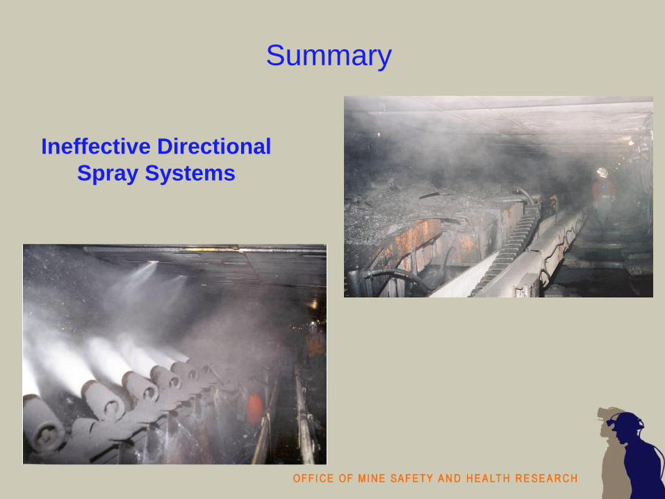
Ineffective Directional
Spray Systems
Summary

Maximum the
Benefits of Available
Controls
Summary

Minimize intake/belt dust
Confine stageloader/crusher dust
Quantity of water in crusher
Gob curtain at HG and beyond
Locate face personnel outby during HG cutout
Shield advance/cutting sequences to minimize exposures of high risk workers
Control Guidelines - Outby
Control Guidelines - Shearer
Optimize cutting parameters (bit maintenance)
Maximize water quantity to drums (larger orifice nozzles)
External sprays @ 150 psi or higher
Caution using crescent sprays on HG drum

Control Guidelines - Shearer
HG splitter arm
• Extend beyond HG drum as far as possible
• Align sprays with airflow
• Maintain belting
• Splitter arm parallel with HG drum
Maintain shearer sprays
Deflector plate as high as possible
Utilize TG side manifold sprays

Control Guidelines - Shields
Underside canopy shield sprays
• Potential to be an effective method at reducing
shearer dust
• Proper sequencing of sprays
• Proper alignment
• Spray water pressure and volume
Advance shields as far away from shearer as possible
depending on roof conditions
Consider uni-directional cutting sequence
Concerted effort to rotate jacksetter operators outby

Commitment to Dust Controls Worker and management involvement
• Knowledge and attitude
• Safety => immediate / Health => long term
Maintenance is critical