controlling the dispersion of nanoparticles in polymer
TRANSCRIPT

University of Tennessee, Knoxville University of Tennessee, Knoxville
TRACE: Tennessee Research and Creative TRACE: Tennessee Research and Creative
Exchange Exchange
Masters Theses Graduate School
12-2006
Controlling the Dispersion of Nanoparticles in Polymer Matrices Controlling the Dispersion of Nanoparticles in Polymer Matrices
Chang-Uk Lee University of Tennessee, Knoxville
Follow this and additional works at: https://trace.tennessee.edu/utk_gradthes
Part of the Engineering Commons
Recommended Citation Recommended Citation Lee, Chang-Uk, "Controlling the Dispersion of Nanoparticles in Polymer Matrices. " Master's Thesis, University of Tennessee, 2006. https://trace.tennessee.edu/utk_gradthes/4461
This Thesis is brought to you for free and open access by the Graduate School at TRACE: Tennessee Research and Creative Exchange. It has been accepted for inclusion in Masters Theses by an authorized administrator of TRACE: Tennessee Research and Creative Exchange. For more information, please contact [email protected].

To the Graduate Council:
I am submitting herewith a thesis written by Chang-Uk Lee entitled "Controlling the Dispersion of
Nanoparticles in Polymer Matrices." I have examined the final electronic copy of this thesis for
form and content and recommend that it be accepted in partial fulfillment of the requirements
for the degree of Master of Science, with a major in Polymer Engineering.
Mark Dadmun, Major Professor
We have read this thesis and recommend its acceptance:
Jimmy Mays, Kevin Kit
Accepted for the Council:
Carolyn R. Hodges
Vice Provost and Dean of the Graduate School
(Original signatures are on file with official student records.)

To the Graduate Council:
I am submitting herewith a thesis written by Chang-Uk Lee entitled "Controlling the Dispersion ofNanoparticles in Polymer Matrices." I have examined the final paper copy of this thesis for form and content and recommend that it be accepted in partial fulfillment of the requirements for the degree of Master of Science, with a major in Polymer Engineering.
Mark Dadmun, Major Professor
We have read this thesis and recommend its acceptance:
r:;;lys �
Accepted for the Council:
raduate Studies

CONTROLLING THE DISPERSION OF NANOPARTICLES
IN POLYMER MATRICES
A Thesis
Presented for the
Master of Science Degree
The University of Tennessee, Knoxville
Chang-Uk Lee
December 2006

ACKNOWLEDGEMENT
I would first like to thank my parents, Byung-Mun Lee and Jeong-Ja Do, for their
endless love and support. I would like to thank my sisters, Kyung-Mi, Sun-Hwa, and
Kyung-A, who always give me confidence.
I would like to thank my advisor, Professor Mark Dadmun, for his leadership,
intelligence, and help to make this research possible. I would like to thank my committee
members, Professor Jimmy Mays and Professor Kevin Kit, for their time and assistance. I
would like to thank my lab members, Rujul Mehta, Sudesh Karnath, Zhenyu Huang,
Nathan Crawford, Kevin Rice, Asif Rasheed, Michael Lay, Nathan Henry, Deepali Kumar,
Earl Ashcraft, Shraddha Deodhar, Brian Bachner, Caleb Dyer, and Diaz Linton, for their
camaraderie and discussions during this research.
I would like to thank Professor Kevin Kit for helpful discussions regarding DMA
sample preparation. I would like to thank Professor Jimmy Mays and Raining Ji for
helpful discussions regarding PSVPh-SH synthesis. Special thanks to Deepali Kumar for
teaching me polymer synthesis.
This research was financially supported by NSF through grants DMR 0241214
and CRC-Chem-0304807.
11

ABSTRACT
The dispersion of nanoparticles in a polymer matrix is a critical parameter to
design and realize targeted morphologies and properties of a final polymer-based
nanocomposite. This thesis presents experimental studies to investigate the dispersion of
nanoparticles in polymer matrices using specific intermolecular hydrogen bonding
between the nanoparticles and polymer matrices under two main topics.
The first topic is the impact of sample preparation processes on the properties of
polymer carbon nanotube nanocomposites. Polymer nanocomposites composed of
poly(styrene-co-vinyl phenol) (PSVPh) copolymers and 5 wt % multi-walled carbon
nanotubes (MWNTs) were prepared from three different methods, including melt-mixing
and solution casting. The MWNTs were either oxidized to incorporate oxygenated defects
or utilized as received. The mechanical properties of the nanocomposites were measured
by DMA, and the extent of intermolecular hydrogen bonding between MWNTs and
PSVPh was quantified by IR. Our DMA results suggest that melt-mixing leads to more
stable morphologies of the final nanocomposites than solution casting does. Additionally,
the IR analysis of the nanocomposites indicates melt-mixing can result in the formation
of more intermolecular hydrogen bonding between the MWNTs and PSVPh than solution
casting, and thus suggests that melt-mixing leads to more reproducible mechanical
properties than solution casting. Our DMA and IR results may provide guidelines to
realize the desired morphologies and to improve the properties of polymer carbon
nanotube nanocomposites by optimizing intermolecular interactions between MWNTs
and polymers.
The other topic examined seeks to synthesize the starting materials to sequester
111
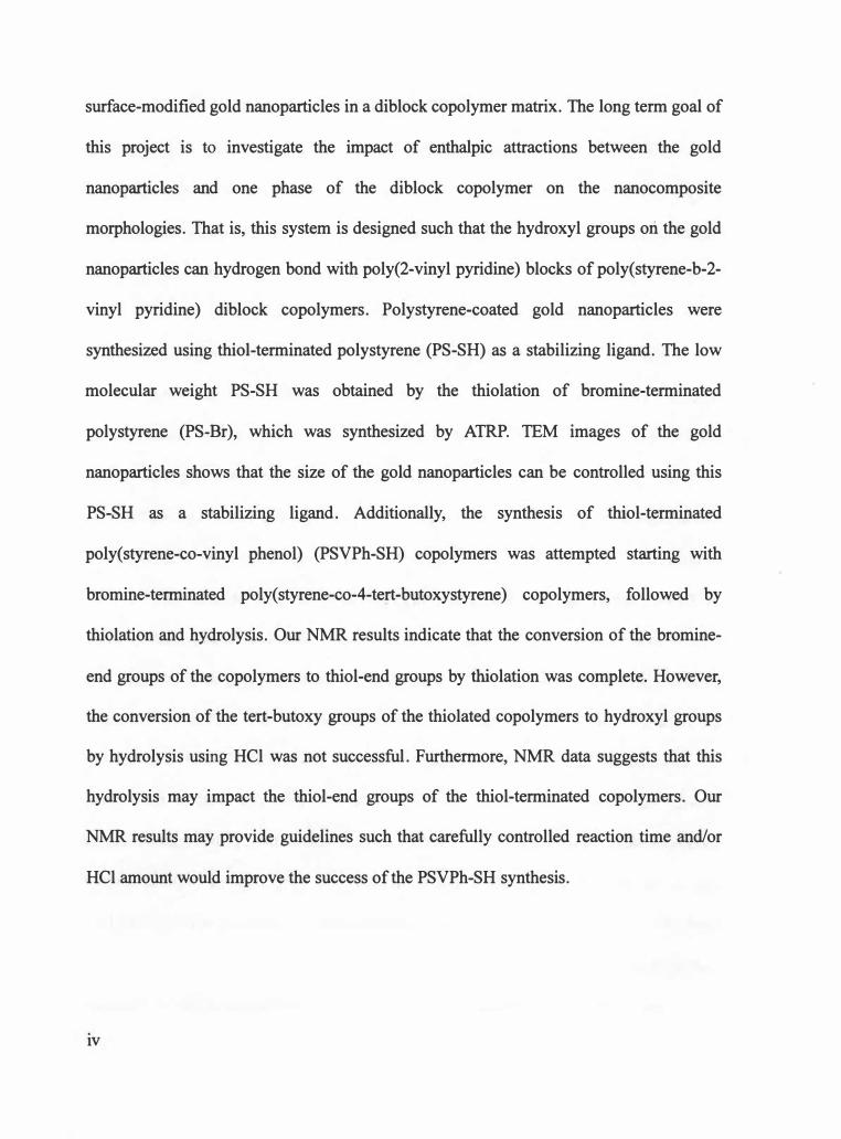
surface-modified gold nanoparticles in a diblock copolymer matrix. The long term goal of
this project is to investigate the impact of enthalpic attractions between the gold
nanoparticles and one phase of the diblock copolymer on the nanocomposite
morphologies. That is, this system is designed such that the hydroxyl groups ori the gold
nanoparticles can hydrogen bond with poly(2-vinyl pyridine) blocks of poly(styrene-b-2-
vinyl pyridine) di block copolymers. Polystyrene-coated gold nanoparticles were
synthesized using thiol-terminated polystyrene (PS-SH) as a stabilizing ligand. The low
molecular weight PS-SH was obtained by the thiolation of bromine-terminated
polystyrene (PS-Br), which was synthesized by ATRP. TEM images of the gold
nanoparticles shows that the size of the gold nanoparticles can be controlled using this
PS-SH as a stabilizing ligand. Additionally, the synthesis of thiol-terminated
poly(styrene-co-vinyl phenol) (PSVPh-SH) copolymers was attempted starting with
bromine-terminated poly(styrene-co-4-tert-butoxystyrene) copolymers, followed by
thiolation and hydrolysis. Our NMR results indicate that the conversion of the bromine
end groups of the copolymers to thiol-end groups by thiolation was complete. However,
the conversion of the tert-butoxy groups of the thiolated copolymers to hydroxyl groups
by hydrolysis using HCl was not successful. Furthermore, NMR data suggests that this
hydrolysis may impact the thiol-end groups of the thiol-terminated copolymers. Our
NMR results may provide guidelines such that carefully controlled reaction time and/or
HCl amount would improve the success of the PSVPh-SH synthesis.
IV

TABLE OF CONTENTS
CHAPTER 1 ....................................................................................................................... 1
INTRODUCTION .............................................................................................................. 1
1.1 Dispersion of Nanoparticles in Polymer Matrices: Introduction and Literature
Review ...................................................................................................................... 1
1.2 The Impact of Sample Preparation on Polymer Carbon Nanotube Nanocomposites6
1.2.1 Carbon Nanotubes as a Filler ............................................................................. 6
1.2.2 Chemical Functionalization of CNTs ................................................................. 9
1.2.3 Nanocomposite Preparation Processes ............................................................. 11
1.3 Sequestering Surface-modified Gold Nanoparticles in Diblock Copolymers:
Starting Materials.................................................................................................... 14
CHAPTER 2 ..................................................................................................................... 19
THE IMPACT OF SAMPLE PREPARATION ON POLYMER CARBON NANOTUBE
NANOCOMPOSITES ...................................................................................................... 19
2.1 Experimental ........................................................................................................... 19
2.1.1 Synthesis of Poly( styrene-co-vinyl phenol) (PSVPh) ...................................... 19
2.1.2 Oxidation of Multi-walled Carbon Nanotubes and Raman Spectroscopy of
MWNTs ........................................................................................................... 20
2.1.3 Preparation of Nanocomposites ....................................................................... 23
2.1.4 Dynamic Mechanical Analysis (DMA) ........................................................... 26
2.1.5 Infrared (IR) Spectroscopy .............................................................................. 27
2.1.6 Raman Spectroscopy and Scanning Electron Microscopy .............................. 28
2.2 Results and Discussion ........................................................................................... 28
V

2.2.1 PSVPh Copolymer Characterization ............................................................... 28
2.2.2 Characterization of MWNTs ............................................................................ 31
2.2.3 Dynamic Mechanical Analysis ........................................................................ 34
2.2.4 Infrared Spectroscopy of Nanocomposites: Correlate Mechanical Properties
with Intermolecular Interactions ....................................................................... 4 7
2.3 Conclusions ............................................................................................................. 59
CHAPTER 3 ..................................................................................................................... 60
SEQUESTERING SURFACE-MODIFIED GOLD NANOPARTICLES IN DIBLOCK
COPOLYMERS: STARTING MATERIALS ................................................................... 60
3 .1 Experimental ........................................................................................................... 60
3.1.1 Synthesis of Thiol-terminated Polystyrene ...................................................... 60
3.1.2 Synthesis of Polystyrene-coated Gold Nanoparticles ...................................... 61
3.1.3 Transmission Electron Microscopy {TEM) of Gold Nanoparticles ................. 63
3 .1.4 Synthesis of Bromine-terminated Poly( styrene-co-acetoxystyrene) Copolymers,
and their Hydrolysis or Thiolation .................................................................... 64
3.1.5 Synthesis of Thiol-terminated Poly(styrene-co-vinyl phenol) Copolymers .... 65
3 .2 Results and Discussion ........................................................................................... 68
3.2.1 Bromine-terminated Polystyrene ..................................................................... 68
3.2.2 Thiol-terminated Polystyrene ........................................................................... 70
3.2.3 Polystyrene-coated Gold Nanoparticles ........................................................... 70
3.2.4 Attempt for Synthesis of Thiol-terminated Poly(styrene-co-vinyl phenol)
Copolymers Starting with Bromine-terminated Poly( styrene-co-acetoxystyrene)
Copolymers ....................................................................................................... 73
Vl

3.2.5 Bromine-terminated Poly(styrene-co-4-tert-butoxystyrene) Copolymers ....... 78
3.2.6 Thiol-terminated Poly(styrene-co-4-tert-butoxystyrene) Copolymers ............ 78
3.2.7 Hydrolysis of Thiol-terminated Poly(styrene-co-tert-butoxystyrene)
Copolymers ....................................................................................................... 80
3.3 Conclusions ............................................................................................................. 84
CHAPTER 4 ..................................................................................................................... 86
CONCLUSIONS AND FUTURE WORK ....................................................................... 86
LIST OF REFERENCES .................................................................................................. 92
VITA ................................................................................................................................. 97
vii

LIST OF TABLES
Table 2.1 Summary of Raman spectroscopy of MWNTs treated with various oxidizing
agents or untreated MWNTs . ............................................................................ 33
Table 2.2 Summary of peak-fitting results for nanocomposites from three different
sample preparation procedures . ........................................................................ 55
Vlll

LIST OF FIGURES
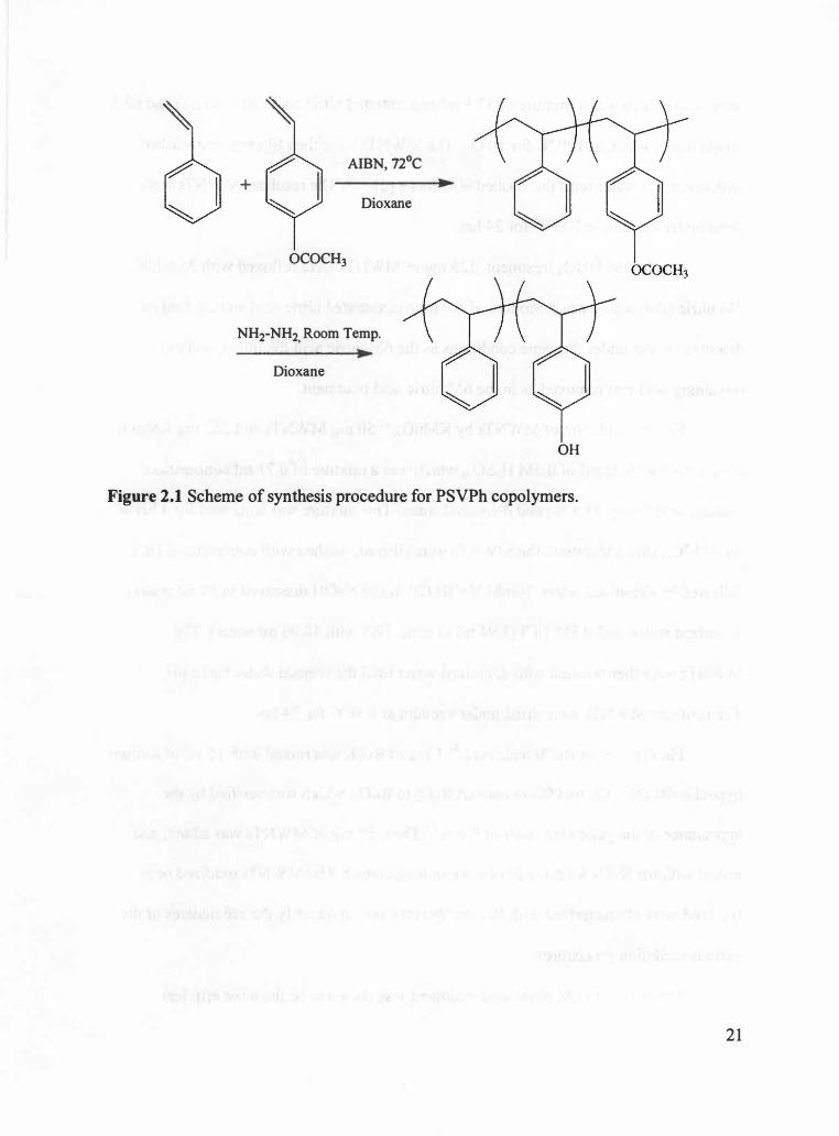
Figure 2.1 Scheme of synthesis procedure for PSVPh copolymers .................................. 21
Figure 2.2 Scheme of sample preparation processes for polymer carbon nanotube
nanocomposites. MM: Melt-Mixing process, SCM: Solution-Casting after
Melt-mixing, and SCD: Solution-Casting after Dissolving polymers in
MWNT-DMF suspension ................................................................................ 24
Figure 2.3 1H spectra of (a) poly(styrene-co-acetoxystyrene) copolymers and (b)
poly(styrene-co-vinyl phenol) copolymers after hydrolysis . .......................... 30
Figure 2.4 Raman spectra of oxidized MWNTs from 4 different oxidation processes and
unoxidized MWNTs ........................................................................................ 32
Figure 2.5 Representative SEM images ofMWNTs. (a) unoxidized, (b) 6M nitric acid
treated, and (c) 6M nitric acid and then piranha solution treated MWNTs . ... 35
Figure 2.6 Storage modulus of PSVPh samples prepared from MM (MM_ PSVPh), SCM
(SCM_PSVPh), or SCD (SCD_PSVPh) methods as a function of temperature.
························································································································· 38
Figure 2.7 Storage modulus ratio of MM nanocomposites with oxidized (0) and
unoxidized (x) MWNTs normalized to that of the PSVPh as a function of
temperature {T - Tg) . ...................................................................................... 39
Figure 2.8 Storage modulus ratio of SCM nanocomposites with oxidized and unoxidized
MWNTs normalized to that of the PSVPh as a function of temperature {T -
Tg) ................................................................................................................... 41
Figure 2.9 Storage modulus ratio of SCD nanocomposites with oxidized and unoxidized
MWNTs normalized to that of the PSVPh as a function of temperature (T -
lX

Tg) ................................................................................................................... 43
Figure 2.10 Storage modulus ratio of SCD _ 2nd samples with oxidized or unoxidized
MWNTs to that of PSVPh as a function of temperature (T-Tg) . ............... 44
Figure 2.11 Storage modulus ratio of SCD&MM samples with oxidized or unoxidized
MWNTs to that of PSVPh as a function of temperature (T-Tg) . ............... 46
Figure 2.12 Summary of storage modulus ratio of nanocomposites with oxidized MWNTs
from MM, SCM, or SCD . ............................................................................. 48
Figure 2.13 Summary of storage modulus ratio of nanocomposites with unoxidized
MWNTs from MM, SCM, or SCD . .............................................................. 49
Figure 2.14 Scheme of possible 0-H stretching vibrations in this study . ......................... 51
Figure 2.15 Example of peak-fitted curves of a MM_Oxidized nanocomposite .............. 54
Figure 2.16 The ratio of concentration of free (CF,ott), intra-associated (CA.OH) and inter-
associated (Cr,ott) to that of total OH (Cr,ott) vibration for nanocomposites
with (a) oxidized and (b) unoxidized MWNTs . ............................................ 56
Figure 2. 17 Storage modulus ratio ( +) of MM, SCM, or SCD samples with oxidized or
unoxidized MWNTs normalized to that of the PSVPh as a function of the
ratio of concentration of inter-associated (C1,ott) to that of total OH (Cr,ott)
vibration . ....................................................................................................... 58
Figure 3 .1 Scheme for synthesis procedure of PS-SH48 ................................................... 62
Figure 3.2 Scheme for synthesis procedures for thiol-terminated poly(styrene-co-vinyl
phenol) copolymers starting with bromine-terminated poly(styrene-co-4-tert-
X

butoxystyrene) copolymers . ............................................................................ 66
Figure 3.3 1H spectrum of bromine-terminated polystyrene dissolved in deuterated
chloroform ....................................................................................................... 71
Figure 3.4 1H spectrum of thiol-terminated polystyrene dissolved in deuterated
chloroform ....................................................................................................... 72
Figure 3 .5 Representative TEM image of PS-coated gold nanoparticles. (Scale bar size:
100 nm) ........................................................................................................... 74
Figure 3.6 Size and size distribution of PS-coated gold nanoparticles . ............................ 75
Figure 3.7 1H spectrum of bromine-terminated poly(styrene-co-4-tert-butoxystyrene)
copolymers dissolved in deuterated dioxane . ................................................. 79
Figure 3.8 1H spectrum ofthiol-terminated poly(styrene-co-tert-butoxystyrene)
copolymers dissolved in deuterated chloroform . ............................................ 81
Figure 3.9 1H NMR spectrum of thiol-terminated poly(styrene-co-4-tert-butoxystyrene)
copolymers dissolved in deuterated chloroform after hydrolysis . .................. 82
Figure 4.1 Scheme of future work for sequestering surface-modified gold nanoparticles in
diblock copolymers . ........................................................................................ 91
Xl


CHAPTERl INTRODUCTION
1.1 Dispersion of Nanoparticles in Polymer Matrices: Introduction and Literature Review
Recently, polymer-based nanocomposites composed of polymers and nano-size
fillers 1 have been an important research area in polymer science and engineering in that
the creation of these nanocomposites makes it possible to utilize the mechanical, optical,
or conductive properties of metal or semiconductor nanoparticles within polymer
matrices. 24 Widely used nanoscale fillers include carbon nanotubes, clays, and metal
nanoparticles5, which are classified as nanoparticles in this thesis. The utilization of
nanoparticles in polymer-based composites has been motivated by several advantages
compared to the conventional micro-size fillers. 6 One of the advantages can be to
maximize the efficiency of fillers by increasing interfacial area per particle volume as
nano-size fillers with large surface-area-to-volume ratios are involved in nanocomposites.
Bockstaller et al. 6 demonstrated that the interfacial area per particle volume can increase
from 104 for micro-size fillers such as glass fibers to 10-1 for nano-size fillers such as
clay and spherical nanoparticles. Furthermore, the specific properties of polymeric
materials can be improved while other properties remain unchanged. 1•6 For example,
Kawasumi et al.7 reported the improvement of the heat-distortion property and storage
modulus above Tg of clay-nylon-6 nanocomposites. Specifically, the storage modulus at
120 °C of the nanocomposite with 5 wt % clay increase by three times relative to that of
the neat nylon-6. However, they showed that the nano-size clays in the polymer matrix
1

did not impact the transparency of the nylon-6 film.
Various types of polymers have been used as a matrix, such as homopolymers,
random polymers, and block copolymers, to attempt to tailor nanocomposite
morphologies, which may impact the properties of the nanocomposites. Nanoparticles are
generally incorporated into homopolymers with the main purpose of improving the
mechanical or thermal properties of the polymers.6 For examples, Okada et al.8 reported
the formation of nylon-6/clay nanocomposites with improvement of the tensile strength
(from 69 to 107 MPa) and the tensile modulus (from 1.1 to 2.1 GPa) with 4.2 wt % clays
relative to that of nylon 6. This study shows that homogeneously dispersed clays in
homopolymers can lead to improved mechanical properties of nanocomposites.
Additionally, block copolymers, "which are macromolecules composed of
sequences, or blocks, of chemically distinct repeat units"9, have attracted many
researchers' attention as a polymer matrix in nanocomposites in that the microphase
separation of block copolymers can lead to highly ordered morphologies, such as
lamellae, hexagonally packed cylinder, and body-centered cubic sphere structures by self
assembly processes.9-11 For example, Sita and co-workers12 reported the selective
dispersion of alkanethiol-passivated gold nanoparticles into the polystyrene blocks of
poly( styrene-b-methyl methacrylate ), PS-b-PMMA, di block copolymers, which
microphase-separated into lamellar phases. In this work, chemical compatibility between
the non-polar alkanethiol-coated gold nanoparticles and non-polar PS domains and
chemical incompatibility between the gold nanoparticles and the polar PMMA domains
led to the selective dispersion of the gold nanoparticles into the PS blocks. As a result, the
alkanethiol-coated gold nanoparticles were localized in the PS-domains. This study
2
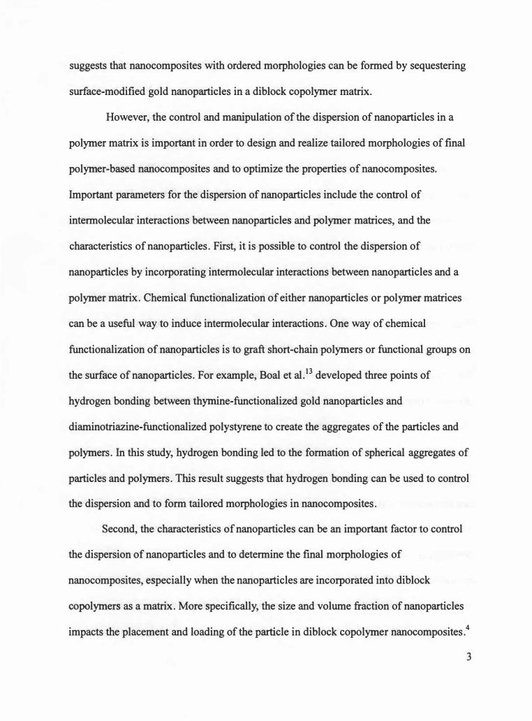
suggests that nanocomposites with ordered morphologies can be formed by sequestering
surface-modified gold nanoparticles in a diblock copolymer matrix.
However, the control and manipulation of the dispersion of nanoparticles in a
polymer matrix is important in order to design and realize tailored morphologies of final
polymer-based nanocomposites and to optimize the properties of nanocomposites.
Important parameters for the dispersion of nanoparticles include the control of
intermolecular interactions between nanoparticles and polymer matrices, and the
characteristics of nanoparticles. First, it is possible to control the dispersion of
nanoparticles by incorporating intermolecular interactions between nanoparticles and a
polymer matrix. Chemical functionalization of either nanoparticles or polymer matrices
can be a useful way to induce intermolecular interactions. One way of chemical
functionalization of nanoparticles is to graft short-chain polymers or functional groups on
the surface of nanoparticles. For example, Boal et al. 13 developed three points of
hydrogen bonding between thymine-functionalized gold nanoparticles and
diaminotriazine-functionalized polystyrene to create the aggregates of the particles and
polymers. In this study, hydrogen bonding led to the formation of spherical aggregates of
particles and polymers. This result suggests that hydrogen bonding can be used to control
the dispersion and to form tailored morphologies in nanocomposites.
Second, the characteristics of nanoparticles can be an important factor to control
the dispersion of nanoparticles and to determine the final morphologies of
nanocomposites, especially when the nanoparticles are incorporated into diblock
copolymers as a matrix. More specifically, the size and volume fraction of nanoparticles
impacts the placement and loading of the particle in diblock copolymer nanocomposites.4
3

For example, Thomas and co-workers 14 prepared nanocomposites composed of
poly(styrene-b-ethylene propylene) (PS-PEP) diblock copolymers, which form lamellar
phases upon microphase separation, and gold or silica nanoparticles, which have
diameters of 3 .5 run and 21.5 run, respectively. The final morphology of the
nanocomposites had the large silica particles located at the center of PEP domains, and
small gold nanoparticles dispersed at the interface of PEP and PS domains. This
experimental result suggests that the dispersion of nanoparticles in a diblock copolymer
matrix can be manipulated by the size of the nanoparticle.
The controlled dispersion of nanoparticles can lead to tailored structures of
nanocomposites, and thus result in a material that is useful in specific applications of
nanocomposites, including chemical sensors and catalysts. 15 For example, one
dimensional structures of particles in a polymer matrix leads to a system that can be
utilized as chemical sensors, in which metal nanoparticles play the role as a provider of
electrical conductivity, and the polymers act as chemical sensors with variable
interparticle distances and interaction sites2 • Krasteva et al.2 developed chemical sensors
composed of gold nanoparticles and three kinds of dendrimers, which were hydrophobic
polyphenylene (PPh) dendrimer, hydrophilic poly(amidoamine) (PAMAM) dendrimers,
and amphiphilic poly(propylene imine) (PPI) dendrimers. Each film of the Au/dendrimer
nanocomposites was tested as a chemical sensor by dosing with vapors of toluene, 1-
propanol, or water. Au/PPh sensors showed the highest resistance when exposed to
toluene vapor, Au/PAMAM with 1-propanol, and Au/PPI with water. The increased
resistance results from the increase of interparticle distances as dendrimers absorb analyte
vapor and swell the polymer chains. This result shows specific morphologies with the
4

dispersed nanoparticles in polymers can lead to specific nanocomposite applications.
Additionally, the aggregate structures of nanoparticle-polymer composites suggest
that they may be good catalysts. 16 As large surface areas are demanded for catalysts,
nanoparticles in a polymer matrix are a good candidate to be used to create such
systems. 15 Galow et al. 16 developed aggregates of acid-functionalized Pd and Si02
nanoparticles with amine-functionalized polymers as the precursor of catalysts. After
calcination of the nanocomposite at 500 °C, highly porous catalysts were obtained. Their
study suggests that nanoparticle-polymer nanocomposites can be fabricated into highly
porous materials, which have the potential to behave as useful as catalysts.
In this study, experimental efforts to design tailored morphologies of polymer
based nanocomposites and to optimize their properties using specific intermolecular
interactions between nanoparticles and polymer matrices were attempted with two
different types of polymer nanocomposites. First, the morphologies of nanocomposites
composed of multi-walled carbon nanotubes (MWNTs) and poly(styrene-co-vinyl
phenol) (PSVPh) random copolymers were studied by investigating the mechanical
properties of the nanocomposites prepared by different sample preparation processes.
Also, the impact of intermolecular interactions between the MWNTs and PSVPh on the
mechanical properties of the polymer nanocomposites was investigated. The MWNTs
were chemically modified to incorporate intermolecular hydrogen bonding with the
polymer matrix, or utilized as received. Additionally, the synthesis of the starting
materials to sequester surface-modified gold nanoparticles in a diblock copolymer matrix
was studied to investigate the impact of intermolecular interactions between the gold
nanoparticles and diblock copolymer on the final morphologies of the diblock copolymer
5

nanocomposites. The synthesis of thiol-terminated short chain polymers to graft on gold
nanoparticle surfaces were attempted to incorporate specific intermolecular hydrogen
bonding between the surface-modified gold nanoparticles and one block of the diblock
copolymer matrix.
1.2 The Impact of Sample Preparation on Polymer Carbon Nanotube Nanocomposites
1.2.1 Carbon Nanotubes as a Filler
Since their report in 1991 17, carbon nanotubes (CNTs) have attracted many
researchers' attention due to their superior mechanical, optical, electrical, and thermal
properties.18 Two common CNTs are single-walled carbon nanotubes (SWNTs) and
multi-walled carbon nanotubes (MWNTs): A SWNT is a hollow and cylindrical structure
that is essentially a rolled up graphite sheet, and a MWNT is more than two SWNTs that
are coaxial along a single hollow axis, in which the gap between tubes is generally
around 0.34 nm.18•19 CNTs have tubular structures of hexagonal network (defect-free
nano tubes), and can also have structures of pentagon or heptagon defects, in which
carbon atoms have sp2 hybridized structures with in-plane o bonding and out-of-plane 1t
bonding. 18 Diameter of SWNTs typically ranges from 0.6- 2 nm, and typical inner
diameter ofMWNTs is greater than 2 nm and outer diameter is less than 100 nm 18•
Length of CNTs ranges up to millimeters.20 This ratio oflength (/) to diameter (d) results
in high aspect ratio (lid) of CNTs. The typical density of CNTs is around 1.3 g/cm3 •20
Due to the extraordinary mechanical properties, low density, and high aspect
ratio, CNTs are a good candidate as a filler for polymer nanocomposites to improve the
6

properties of polymeric materials. In theoretical2 1•22 and experimental23-26 studies, it has
been shown that carbon nanotubes (CNTs) have extraordinary mechanical properties.
First, theoretical studies estimate that the calculated Young's modulus of SWNTs is
higher than 600 GPa. For example, Gao et al.21 calculated Young's modulus of SWNTs
by using molecular dynamics with the modulus in the range of 640 to 673 GPa.
Second, experimentally measured tensile modulus of CNTs has been reported as
high as 1 TPa 19, with tensile strength up to 180 GPa. 19•
27 These values indicates that
CNTs have extraordinary mechanical properties when compared to the bulk modulus and
strength of steel, which are 270 GPa and 1.4 GPa, respectively.28 For example, Wong et
al.23 determined the Young's modulus ofMWNTs by measuring the applied forces for
bending a single nanotube and the displacement of the tube under forces. They fixed one
end of a nanotube on cleaved MoS2 substrate, and allowed the other end to bend as an
atomic force microscope (AFM) tip moves the free end. By the analysis of bending forces
and displacement of 6 nanotubes, they determined the Young's modulus of these MWNTs
to be 1 .28 +/- 0.59 TPa. In addition, Yu et al.24 measured the mechanical properties of
MWNTs by applying tensile stresses to the nanotubes. Due to the nano-size of the tubes,
they attached each end of a single tube to opposite tips of an AFM, applied load to the
tube, and investigated the deformation of tubes using scanning electron microscopy
(SEM). In their work, the measured tensile strengths of 19 individual tubes ranged from
11 to 63 GPa. In addition, based on stress-strain analysis, the Young's modulus (E) of the
tubes was in the range of 270 to 950 GPa.
However, when we incorporate CNTs into a polymer matrix, there can be two
main barriers that must be overcome to utilize the superior properties of CNTs in a
7

polymer matrix.29•3° First, CNTs can easily form aggregates or bundles due to van der
Waals interactions among nanotubes.29 The bundles of CNTs inhibit their solubility in
organic or aqueous solvents, which may result in an inhomogeneous dispersion of CNTs
in a polymer matrix29 • Furthermore, the aggregation of CNTs decreases their aspect ratios,
which reduces their efficiency as fillers. 29 Thus, the uniform and homogeneous dispersion
of CNTs in a polymer matrix is required to optimize CNT nanocomposites. 29•30 Second,
interactions between CNTs and polymer matrices may be weak, which leads to poor
interfacial strength between CNTs and polymers.29 These weak interactions can result in
poor load transfer between CNTs to polymer matrices, and thus decrease their efficiency
as fillers. 29 Therefore, strong interfacial interactions are also desired to create optimal
CNT polymer nanocomposites. 29•30
Many researchers have focused on developing methods to create uniform and
homogenous dispersions of CNTs in polymer matrices and to enhance the interfacial
strength of the CNT/polymer interface in an attempt to enhance the mechanical properties
of CNT nanocomposites. Experimental efforts to improve dispersion of CNTs in
nanocomposites include chemical functionalization of CNTs, which can lead to the
incorporation of intermolecular interactions between CNTs and polymers, and
understanding the role of sample preparation on the ultimate morphology and properties
of polymer CNT nanocomposites.
8

1.2.2 Chemical Functionalization of CNTs
Chemical functionalization of CNTs refers to chemically modifying CNTs in
order to incorporate functional groups on the surfaces. 19 Since intermolecular interactions
between functionalized CNTs and a polymer matrix are possible, chemical
functionalization has been widely utilized as a method to create the uniform dispersion of
CNTs in a polymer matrix, as well as to increase the interfacial strength at the interfaces
between CNTs and polymers.
Specifically, oxygenated defects, such as carbonyl, carboxylic acid, and hydroxyl
groups, can be incorporated onto the surface of CNTs by oxidation of CNTs, which can
occur, for example, by refluxing CNTs with concentrated acids. For example, Wagner and
co-workers29 reported the improved dispersion of SWNTs in poly(vinyl alcohol) (PVA)
matrices and an increased tensile modulus by 79 % of SWNT/PVA nanocomposites
relative to neat PVA by incorporating functional groups on the SWNT that can potentially
hydrogen bond to PVA. They introduced oxygenated defects on SWNTs by mixing
SWNTs with potassium hydroxide (KOH), and the functionalized SWNTs were
characterized by UV-vis spectroscopy, which indicates in this study that the
functionalization of the CNTs changes some of the sp2 bonds of the pristine SWNTs into
sp3 bonds. The nanocomposites composed of functionalized SWNTs and PVA exhibited
higher glass transition temperature (Tg) than neat PVA (68.8 °C � 74.3 °C), which
suggests that potential hydrogen bonding between SWNTs and PVA exists and limited the
molecular motions of PVA chains. Improved dispersion of nanocomposites was shown by
optical microscopy. Their results suggest that functionalization can lead to uniform
9

dispersion of CNTs in a polymer matrix. In addition, the increased intermolecular
interactions, probably hydrogen bonding in this work, between functionalized CNTs and
polymers may result in improved interfacial strength, and thus increase the mechanical
properties of final nanocomposites.
Similarly, Tong and co-workers3 1 functionalized MWNTs by refluxing MWNTs
with a mixture of sulfuric acid and nitric acid in order to induce oxygenated defects on
MWNTs, and prepared nanocomposites of these oxidized MWNTs and the biopolymer
chitosan. They reported the uniform dispersion of the MWNTs in chitosan, which was
shown by optical microscopy, and an improvement of 93% in the tensile modulus of the
chitosan/CNT nanocomposites relative to chitosan. This improvement is attributed to
hydrogen bonding between the oxidized CNTs and the chitosan matrices. This result
suggests that intermolecular hydrogen bonding between functionalized CNTs can result
in better dispersion of CNTs and increased mechanical properties of polymer CNT
nanocomposites.
In addition to the oxygenated defects on CNTs, Geng et al. 32 reported
nanocomposites, which are composed of poly( ethylene oxide) (PEO) and fluorinated
SWNTs (F-SWNTs) for potential intermolecular interactions between the functionalized
SWNTs and PEO matrix. Upon the incorporation of 4 wt % F-SWNTs in the PEO matrix,
the room temperature storage modulus of the nanocomposites increased by 400 %
compared to pure PEO (0.3 GPa to 1.2 GPa). However, they indicated that mechanical
properties of nanocomposites with pristine SWNTs were not improved with the same
loading of the SWNTs. Their results suggest that chemical modification of CNTs can lead
to the enhanced mechanical properties of nanocomposites with potential intermolecular
10

interactions.
1.2.3 Nanocomposite Preparation Processes
Several sample preparation processes, which include melt-mixing and solution
casting, have been applied to polymer CNT nanocomposites as methods to create uniform
and homogeneous dispersions of CNTs in polymer matrices. Experimental results show
that the dispersion of CNTs, the interfacial strength between fillers and polymers, and
consequently the mechanical properties of nanocomposites can be altered by varying the
sample preparation method.
First, melt-mixing is a method to prepare nanocomposites by applying a shear
field at high temperature to the polymer and CNT mixture. 19 Zhang et al. 30 prepared
nanocomposites composed of polyamide 6 (PA6, nylon-6) and 1 wt % MWNTs, which
were treated with nitric acid, by melt-mixing. They melt-mixed PA6 and MWNTs using a
twin-screw mixer at 250 °C for 10 min with 100 rpm screw rotation speed. They reported
the homogeneous dispersion of MWNTs in PA6 matrices, which was shown by imaging
the fracture surfaces of the nanocomposite with scanning electron microscopy (SEM).
Also, based on SEM images, the strong interfacial strength between MWNTs and PA6
was observed through the stretched and deformed MWNTs in the nanocomposite fracture
surfaces. They reported the elastic modulus of nanocomposites with 1 wt % MWNTs and
PA6 was higher by 115 % compared to that of neat PA6 (from 396.5 MPa to 852.4 MPa).
Similarly, Yang et al.33 prepared nanocomposites, which were composed of
atactic polypropylene (aPP) and MWNTs, by melt-mixing and analyzed the dynamic
mechanical properties of the resultant nanocomposites. Specifically, they melt-mixed aPP
11

and MWNTs at 80 °C for 30 mins by using a Brabender mixer. They report that the
storage modulus (E') of the nanocomposites improved as the weight fraction of MWNTs
increased from O to 5 wt %. In addition, they showed the uniform dispersion of the
MWNTs in an aPP matrix by fracture surface images from SEM. These results suggest
that melt-mixing can be a useful method to improve the mechanical properties of
MWNTs in a polymer matrix.
Solution-casting is also a nanocomposite preparation process that entails
blending polymers and CNTs in solution, and obtaining the final nanocomposites by
solvent evaporation or precipitation in a non-solvent. 19 Qian et al. 34 prepared solution
cast polystyrene(PS)/MWNT nanocomposites, and showed an increase of36-42 % in
the elastic modulus of the nanocomposites by adding 1 wt % MWNTs. They dissolved PS
in toluene, and dispersed separately MWNTs in toluene by sonication. The polymer
solution and MWNT suspension were then mixed together, and the final nanocomposites
were recovered by evaporating the toluene. In addition to the improved mechanical
properties, the uniform dispersion of MWNTs in a PS matrix was shown by TEM images
of the nanocomposite films. Their work documents that a solution-casting process can be
a facile and useful way for preparing polymer CNT nanocomposites.
Additionally, Du et al.35 prepared nanocomposites composed of poly(methyl
methacrylate) (PMMA) and SWNTs by blending PMMA and SWNTs in solution and
precipitating in a non-solvent. They dissolved PMMA in dimethylformamide (DMF), and
successively added the mixture of SWNTs and DMF, which was sonicated to improve the
dispersion of the SWNTs in DMF. The mixture of PMMA and SWNTs in DMF were then
precipitated in water. The homogeneous dispersion of SWNTs was observed by optical
1 2

microscopy. In addition, they presented results that showed elastic modulus of
nanocomposites increased as the weight fraction of SWNTs increased from 0.5 to 2 wt %.
However, there still remain many challenges to creating a CNT-polymer
nanocomposite with targeted dispersion for the optimal utilization of CNT in polymer
nanocomposite. Furthermore, an investigation of the relationship between sample
preparation processes and the dispersion of the CNTs, the intermolecular interactions
between polymers and CNTs, and the final properties of nanocomposites has rarely been
reported. In this study, the impact of the sample preparation process on the dispersion and
properties of polymer MWNT nanocomposites is presented. Additionally, the impact of
intermolecular interactions between the MWNT and polymer matrix on the mechanical
properties of the polymer nanocomposites was also investigated. N anocomposites, which
are composed of 5 wt % MWNTs and poly(styrene-co-vinyl phenol) (PSVPh) random
copolymers with 15 % of mole fraction of vinyl phenol groups, were prepared by three
different sample preparation processes including melt-mixing and solution casting. The
15 % mole fraction of vinyl phenol groups of PSVPh was chosen from previous work in
our lab. 36 Rasheed and coworkers36 prepared nanocomposites composed of 5 wt %
SWNTs or MWNTs and PSVPh with 0, 10, 20, 30, and 40 % mole fraction of vinyl
phenol groups by solution casting. They analyzed the nanocomposites by IR to quantify
the extent of intermolecular hydrogen bonding between the nanotubes and PSVPh, and
measured tensile properties and electrical conductivity of the nanocomposites. In their
work, it was shown that the optimum copolymer composition was 20 % vinyl phenol, in
that this copolymer led to the formation of maximum intermolecular hydrogen bonding
between the nanotubes and PSVPh, and optimal properties. In this study, we attempted to
13

synthesize 20 % vinyl phenol copolymers. However, the synthesis resulted in 15 % vinyl
phenol copolymers, which were used in these experiments since we expect this to be
sufficient to study the impact of intermolecular interactions on the properties of the
nanocomposites. MWNTs were either oxidized to incorporate oxygenated defects or
utilized as received. The mechanical properties of the resultant nanocomposites were
characterized by dynamic mechanical analysis (DMA), and the extent of intermolecular
hydrogen bonding between MWNTs and PSVPh matrices were quantified by infrared
(IR) spectroscopy in order to correlate the extent of intermolecular interactions with the
mechanical properties of nanocomposites and the importance of sample preparation
technique on each of these molecular level parameters.
1.3 Sequestering Surface-modified Gold Nanoparticles in Diblock Copolymers: Starting Materials
Polymer based nanocomposites, which are composed of inorganic nanoparticles
and block copolymers can be utilized in a variety of applications, such as photonic
bandgap materials, optoelectronic materials, next-generation catalysts, and chemical
sensors.4•1 0
•1 5 In order to obtain the required and tailored morphologies of the
nanocomposites for these applications, the control and manipulation of sequestering
nanoparticles in block copolymer matrices is needed. 1 0 Several theoretical and
experimental studies to understand and observe the morphology of nanoparticle/block
copolymer nanocomposites have been completed.
A theoretical understanding of the parameters that impact the morphology of
nanoparticle/block copolymer nanocomposites was introduced by Balazs and co-
14

workers. 4 They report the simulation of the dispersion of spherical, hard nanoparticles
into diblock copolymers by applying self-consistent field theory (SCFT) and density
functional theory (DFn. To examine the importance of the affinity between the particles
and polymer chains in specific domains of block copolymers, the Flory-Huggins
interaction parameter, X, which quantifies the enthalpic interaction between particles and
polymers,6 was incorporated into the simulation. For nanocomposites that include particle
(P) and A-B diblock copolymers, the interaction parameter between the particles and the
A chains, XAP, was set to zero by assuming particle surfaces are chemically identical to
the A block of the diblock copolymers. In addition, the other interaction parameters,
which are XBP, XBA, and XAB, were set to positive values, thus incorporating repulsive
interactions between B chains and particles, and between B chains and A chains.
In this simulation, Balazs and co-workers show that the size and volume
fractions of particles, as well as the characteristic of block copolymers impact the final
morphology of the nanoparticle/block copolymer nanocomposites. Specifically, the size
of the particles leads to different placement of the nanoparticle in the final nanocomposite.
The large particles (R = 0.3Ro, R is the radius of a particle and Ro is a root mean square
end-to-end distance of the A block of the copolymer) self-assembled at the center of A
domains. On the other hand, small particles (R = 0.2Ro) localize at the interface between
the two blocks of the diblock copolymers. They explain that this result shows that the
change in entropy of the polymer chains when the nanoparticle is introduced is the main
factor that determines the final morphology of the di block nanocomposites. Specifically,
when large particles are used, the conformational entropy of the A chains is the main
factor that determines the nanocomposite morphology. In contrast, when small particles
15

are used, the translational entropy of the A chains is dominant in determining the final
nanocomposite morphology.
Additionally, Balazs and co-workers37 generalized their results by including
various interactions between particles and polymer chains: particles can interact with
both A or B blocks in A-B-type diblock copolymer systems. In this simulation, they set
XAP to be zero, but XBP varies from -1 to + 1. The result of this simulation is that changing
the various interactions between particles and polymers can impact the final
nanocomposite morphologies. For example, for a nanocomposite that consists of large
particles and diblock copolymers with 0.3 mole fraction A chains, a phase transition from
the cylindrical phase to the lamellar morphology can occur with increasing XBP from -1 to
+ 1. This study suggests that the final morphologies of nanocomposites can be impacted
by varying the specific interactions between particles and polymers.
Several experimental efforts have been reported that sequester surface-modified
inorganic nanoparticles in block copolymer systems. In most experimental cases, the
enthalpic contributions between surface-modified particles (P) and polymer chains in one
(A) of the blocks in di block copolymers, XAP, is zero, i.e. neutral. Additionally, the
enthalpic interaction between the particles and the other block (B) in A-B diblock
copolymers, XBP, is usually positive, i.e. repulsive.
For example, Hashimoto and co-workers1 1 reported sequestering surface
modified palladium (Pd) nanoparticles in a poly(2-vinly pyridine )-b-polyisoprene di block
copolymer (P2VP-b-PI), which microphase-separated into lamellar phases. The Pd
nanoparticle surfaces were modified with poly(2-vinyl pyridine) (P2VP) homopolymers.
In this work, P2VP-coated Pd nanoparticles were located at the center of the P2VP
16

lamellar domains in P2VP-b-PI diblock copolymers. This result suggests that
sequestering the gold nanoparticles in the diblock copolymers results from the neutral
interactions between the P2VP-coated Pd nanoparticles and the P2VP domain in the
diblock copolymers, and the repulsive interactions between the P2VP-coated Pd
nanoparticles and PI domains in the diblock copolymers.
Also, Thomas and co-workers38 sequestered polystyrene (PS)-coated gold
nanoparticles in poly(styrene-b-ethylenepropylene) diblock copolymers, which
microphase-separated into lamellar phases. They reported that PS-coated nanoparticles
were homogeneously dispersed in the PS domains in the diblock copolymers. In this
work, repulsive interactions between the aromatic chain-coated gold nanoparticles and
the aliphatic chains of the PEP block of the copolymer and neutral interactions between
the PS-coated gold nanoparticles and the PS domains of the di block copolymers control
the placement of the nanocomposite in this system. As a result, the selective dispersion of
nanoparticles in the diblock microphases was shown in this work.
Finally, Kramer and co-workers39 reported sequestering either polystyrene (PS)
coated gold nanoparticles or gold nanoparticles coated with a 1 : 1 mixture of PS and
poly(2-vinyl pyridine) (PVP) chains in poly(styrene-b-2-vinyl pyridine) (PS-b-P2VP)
diblock copolymers, which microphase-separated into lamellar phases. In this work, PS
coated gold nanoparticles located at the center of the PS domains in the di block
copolymers. On the other hand, PS/PVP-coated gold nanoparticles were dispersed at the
interface of PS lamellar domains and PVP lamellar domains in the di block copolymers.
These experimental results also show that nanoparticles can be sequestered in specific
domains in diblock copolymers by controlling the repulsive and neutral interactions
17

between nanoparticles and polymers.
Little work, however, on diblock nanocomposites that incorporate attractive
interactions between one of the blocks and the nanoparticles has been reported. Thus, in
this study, the synthesis of starting materials to investigate a different approach for
sequestering surface-modified gold nanoparticles in diblock copolymer systems is
attempted. The long term goal is to investigate the diblock copolymer nanocomposites
that incorporate enthalpic attractions between nanoparticles and polymer chains in one of
the domains in diblock copolymers. That is, the system is designed such that XAP is
negative by incorporating attractive hydrogen bonding between the gold nanoparticles
and one of the blocks of the diblock copolymers.
Specifically, the synthesis of thiol-terminated poly(styrene-co-vinyl phenol)
(PSVPh) random copolymers was attempted starting with bromine-terminated
poly(styrene-co-4-tert-butoxystyrene) random copolymers by atom transfer radical
polymerization (ATRP), followed by thiolation and hydrolysis. The thiol-terminated
polymers can be utilized as a stabilizing ligand to synthesize PSVPh-coated gold
nanoparticles in future work. The hydroxyl groups on gold nanoparticles can hydrogen
bond with one block such as poly(2-vinyl pyridine) blocks of poly(styrene-b-2-vinyl
pyridine) di block copolymers. In addition, for this future study, gold nanoparticles, on
which short-chain polystyrene (PS) were coated, were synthesized starting with bromine
terminated PS which was synthesized by ATRP, followed by thiolation.
18

CHAPTER 2
THE IMPACT OF SAMPLE PREPARATION ON POLYMER CARBON NANOTUBE NANOCOMPOSITES
2.1 Experimental
2.1.1 Synthesis of Poly(styrene-co-vinyl phenol) (PSVPh)
Poly(styrene-co-vinyl phenol) (PSVPh) random copolymers with 15% mole
fraction of vinyl phenol groups were synthesized by synthesizing poly(styrene-co
acetoxystyrene) random copolymers via free radical polymerization followed by the
hydrolysis of poly(styrene-co-acetoxystyrene) to poly(styrene-co-vinyl phenol). Styrene,
4-acetoxystyrene, 1,4-dioxane, 2,2' -azobisisobutyronitrile (AIBN), tetrahydrofuran
(THF), and hydrazine hydrate were purchased from Aldrich, and utilized as received
without further purification. The monomers, which were 255 ml of styrene and 45 ml of
4-acetoxystyene, were added to a 1000 ml three-neck, round-bottom flask, in which 0.126
g of 2,2'-azobisisobutyronitrile (AIBN) as an initiator were dissolved in 270 ml of
anhydrous 1,4-dioxane, which was a solvent in this polymerization. All reactants were
degassed by freeze-thaw processes repeated four times. The polymerization was
conducted under nitrogen in an oil bath at 72 °C for 23 hrs. After polymerization, the
resultant polymers were purified to remove unreacted monomers and solvent by
dissolving in tetrahydrofuran (THF), precipitating in cold methanol, and drying under
vacuum at 100 °C for 24 hrs. This purification process was repeated three times. The
purified polymers were characterized by gel permeation chromatography (GPC) to
measure molecular weight, and by nuclear magnetic resonance (NMR) to determine the
19

composition of the copolymer.
The hydrolysis of poly(styrene-co-acetoxystyrene) copolymers was completed to
convert the acetoxy groups to hydroxyl groups. In a typical hydrolysis reaction, 40 g of
poly(styrene-co-acetoxystyrene) was completely dissolved in 300 ml of dioxane, and then
120 ml of hydrazine hydrate was added into the polymer solution. This mixture was
vigorously stirred under argon gas flow for 60 hrs at room temperature. After 60 hrs, the
polymer was precipitated in cold methanol, filtered, and dried under vacuum at 120 °C
for 3 8 hrs. The resultant polymers were characterized by GPC to determine molecular
weight. NMR was utilized to verify the conversion of acetoxy groups to hydroxyl groups.
Figure 2.1 shows the chemical equation to synthesize PSVPh copolymers.
2.1.2 Oxidation of Multi-walled Carbon Nanotubes and Raman Spectroscopy of MWNTs
The oxidation of multi-walled carbon nanotubes (MWNTs) was conducted to
incorporate oxygenated defects onto multi-walled carbon nanotubes (MWNTs). In order
to determine the optimum oxidation processes, four different oxidations, including 6M
HN03, 3M HN03, K.Mn04, and Ru04, were conducted, and as described in section 2.2.2,
the best option which was the 6M HN03 treatment was chosen to oxidize the MWNTs to
prepare polymer MWNT nanocomposites. MWNTs were purchased from N anolab
(Newton, MA, USA), and used as received without further purification processes. The
outer diameters of the received MWNTs range from 10 to 20 nm, inner diameters from 5
to 9 nm, and lengths from 1 to 5 microns. 40
For the 6M HN03 treatment,41 0.5 g MWNTs was refluxed in 100 ml of 6M
20
AIBN, 72°C
+
Dioxane
OCOCH3
NHrNH2, Room Temp.
Dioxane
OH
Figure 2.1 Scheme of synthesis procedure for PSVPh copolymers.
21

nitric acid, which was a mixture of 3 7 .5 ml concentrated nitric acid (70 % assay) and 62.5
ml deionized water, at 120 °C for 16 hrs. The MWNTs were then filtered, and washed
with deionized water until the washed H20 had a pH - 7. The resultant MWNTs were
dried under vacuum at 100 °C for 24 hrs.
For the 3M HN03 treatment, 125 mg of MWNTs were refluxed with 25 ml of
3M nitric acid, which was a mixture of 4. 7 ml concentrated nitric acid and 20.3 ml of
deionized water under the same conditions as the 6M nitric acid treatment, and any
remaining acid was removed as in the 6M nitric acid treatment.
For the oxidation of MWNTs by KMn04,41 50 mg MWNTs and 262 mg KMn04
were mixed with 25 ml of 0.5M H2S04, which was a mixture of 0.71 ml concentrated
sulfuric acid ( assay 9 5 .4 % ) and deionized water. This mixture was sonicated for 4 hrs at
40 - 45 °C. After sonication, the MWNTs were filtered, washed with concentrated HCl,
followed by deionized water, 1 OmM NaOH (20 mg of NaOH dissolved in 50 ml water),
deionized water, and 0.5M HCl (1.94 ml of cone. HCl with 48.06 ml water). The
MWNTs were then washed with deionized water until the washed water had a pH - 7.
The resultant MWNTs were dried under vacuum at 100 °C for 24 hrs.
Finally, for the Ru04 treatment,41 1 mg of Ru02 was mixed with 15 ml of sodium
hypochlorite (NaOCl, 6wt %) to convert Ru02 to Ru04, which was verified by the
appearance of the yellowish color of Ru04.41 Then, 50 mg of MWNTs was added, and
mixed with the Ru04 for three days at room temperature. The MWNTs oxidized or as
received were characterized with Raman spectroscopy to quantify the efficiencies of the
various oxidation procedures.
MWNTs with 6M nitric acid treatment was shown to be the most efficient
22

oxidation process among the 4 different oxidation procedures as described in section
2.2.2, was further purified with piranha solution to remove amorphous carbon, which is
generated during the oxidation process.41 In this process, 410 mg of MWNTs were mixed
with 100 ml piranha solution ( a mixture of H2S04 and H202 in 4 to 1 volume ratio) and
refluxed for 30 minutes at 70 °C. After piranha solution treatment, this mixture was
diluted with deionized water, filtered, and washed with deionized water until the pH -- 7.
The final product was dried under vacuum at 100 °C for 24 hrs. These MWNTs, which
were treated with 6M nitric acid and piranha solution, were utilized to prepare
nanocomposites, and hereafter these MWNTs are called "oxidized MWNTs."
2.1.3 Preparation of Nanocomposites
Nanocomposites with oxidized MWNTs or unoxidized MWNTs were prepared
with three different preparation procedures including melt-mixing and solution casting.
Figure 2.2 illustrates the three nanocomposite preparation procedures used in this study.
The first method is a melt-mixing process, which is developed to mimic the
process reported by Baskaran et al. 42 This method is denoted by "MM" in this study. In
this process, 4.8 g of PSVPh copolymers were dissolved in 48 ml dimethylformamide
(DMF). Either 0.24 g of oxidized or unoxidized MWNTs were separately sonicated using
a Branson 2510 sonicator (Branson Ultrosonics Corporation, Danbury, CT, USA) in 240
ml DMF for 15 mins. The PSVPh polymer solution was added into this MWNT
suspension in DMF, and sonicated for an additional 15 mins. This polymer/MWNT
mixture in DMF was precipitated in cold methanol, filtered, and dried under vacuum at
120 °C for 30 hrs. These pre-nanocomposites were then melt-mixed using an Atlas
23

Melt-mixing (MM)
l� I + � �l DMF
Sonication ( 15min)
� Sonication ( 15min) MeOH! Dry
� Melt-mixing ! 180oC, 1 5min
Solution Casting (SC)
Melt-mixing + Dissolving (SCM)
Melt-mixed nanocomp.
!
rl!J MeOH! Dry
l Dissolving PSVPh in
MWNT-DMF suspension (SCD)
� .,.,_,
DMF
Sonication ( 1hr) � i � MeOH! Dry � � PSVPh
MWNT
Figure 2.2 Scheme of sample preparation processes for polymer carbon nanotube nanocomposites. MM: Melt-Mixing process, SCM: Solution-Casting after Melt-mixing, and SCD: Solution-Casting after Dissolving polymers in MWNT-DMF suspension.
24

laboratory mixing molder (Atlas Electronic Devices, Chicago, USA) at 180 °C for
15mins with 60 rpm rotation speed. Hereinafter, the nanocomposites with oxidized
MWNTs from this method are denoted by "MM_ Oxidized," and nanocomposites with
unoxidized MWNTs by "MM_ Unoxidized."
Additionally, pure PSVPh copolymers without MWNTs were treated with the
same procedures as the melt-mixed nanocomposites to precisely investigate the
improvement of mechanical properties of the polymers with the incorporation of MWNTs.
More specifically, 4.8 g of PSPVh copolymer was dissolved in 48 ml of DMF. 240 ml of
DMF without MWNTs was separately sonicated for 15 min. Then the polymer solution
was added into the DMF, which was sonicated, and then this solution was sonicated for
additional 15 mins. The polymers were precipitated in cold methanol, filtered, and dried
under vacuum at 120 °C for 30 hrs. Then this polymer was melt-mixed under the same
conditions as the nanocomposite.
In addition to the melt-mixing process, two solution-casting methods were
applied to prepare nanocomposites. The second method is a procedure that consists of
melt-mixing, dissolving of the melt-mixed nanocomposites in DMF, and solution-casting.
This procedure is denoted by "SCM," which refers to "solution casting after melt
mixing." In this procedure, 2.54 g of the melt-mixed nanocomposites from the MM
method was completely dissolved in 181 ml of DMF (1.4 wt % of nanocomposites in
DMF). Then, this mixture was precipitated in cold methanol. The final nanocomposite
products were dried under vacuum at 120 °C for 30 hrs, and compression-molded for
DMA as described in section 2.1.4. Nanocomposites with oxidized MWNTs from this
method are denoted by "SCM_Oxidized," and nanocomposites with unoxidized MWNTs
25

by "SCM_Unoxidized." Melt-mixed PSVPh samples were also dissolved under the same
conditions as the nanocomposite.
Finally, a third procedure, solution casting, was applied to prepare
nanocomposites. This procedure is denoted by "SCD," which refers to solution-casting
after dissolving polymers in DMF-MWNT suspension. In this procedure, 0.12 g MWNTs
was separately sonicated in 180 ml DMF for 1 hr. Then, 2.4 g of PSVPh copolymers were
added into this MWNT-DMF suspension, and completely dissolved. This polymer
MWNT solution was then precipitated in cold m�thanol and filtered. The final
nanocomposite products were dried under vacuum at 120 °C for 30 hrs to remove any
remaining solvent. N anocomposites with oxidized MWNTs from this method are denoted
by "SCD _ Oxidized," and nanocomposites with unoxidized MWNTs by
"SCD _ Unoxidized." Additionally, PSVPh copolymers were treated with this procedure
without MWNTs.
2.1.4 Dynamic Mechanical Analysis (DMA)
The mechanical properties of PSVPh and polymer carbon nanotube
nanocomposites were analyzed by DMA (DMA Q800, TA instrument, New Castle, DE,
USA) by applying a sinusoidal force with constant 1 Hz frequency from 25 °C to 145 °C
for the PSVPh samples and 25 °C to 175 °C for the nanocomposite samples with a
heating rate of 2 °C/min. The storage modulus (E'), loss modulus (E"), and tan( 8 ) were
obtained by analyzing the relationship between the applied forces and the resultant
strain.32 The samples for DMA were prepared by compression-molding. Specifically,
nanocomposite and PSVPh samples, which were cut into small pieces or ground into fine
26

powders, were loaded onto a rectangular template on a Carver laboratory hydraulic press
(Fried S. Carver Inc., Monomonee Falls, WI, USA), and heated at 180 °C for 52 mins,
which was regarded as enough time for nanocomposites or polymers to flow, and for
possible porosity inside the samples to be removed. 2,500 psi pressure was then applied
to the samples for 3 mins at 180 °C, and the template with the sample was slowly cooled
under pressure until the temperature was around 50 °C. Then resultant rectangular
samples, of which dimensions were 34.50-35.00 mm in length, 13.90-14.40 mm in
width, and 1.2 - 1.3 mm in thickness, were separated from the template. The dimensions
of each sample were carefully measured by calculating the average sizes of at least 10
spots of each sample, and this geometrical information was used to analyze the DMA
data.
2.1.5 Infrared (IR) Spectroscopy
The intermolecular interactions between PSVPh and MWNTs were quantified by
Fourier transform infrared spectroscopy (IR, Biored FTS-6000e ). A PSVPh sample was
scanned 1024 times with the range of 400 - 4000 cm· 1 wavenumber at 4 cm· 1 resolution.
Spectroscopic information was corrected for KBr background information.
Nanocomposite samples were characterized under the same condition as PSVPh sample
analysis except for the number of scans, which were 25,000. Samples for IR were
prepared by mixing 5 mg of pure copolymers or nanocomposites with 95 mg of
potassium bromide (KBr), compressing this mixture into an IR pellet, and drying the
compressed films under vacuum for 24 hrs at 100 °C.
27

2.1. 6 Raman Spectroscopy and Scanning Electron Microscopy
MWNTs were characterized on Raman spectroscopy with a JY LabRam
spectrometer using a CCD detector and He-Ne laser at 632.1 nm wavelength. The surface
structures of MWNTs before and after oxidation were characterized using scanning
electron microscopy (SEM, LEO 1525) with a 5 kV voltage using the in-lens detector as
a secondary electron detector.
2.2 Results and Discussion
2.2.1 PSVPh Copolymer Characterization
GPC is widely used by polymer researchers to determine the molecular weight
properties of polymers. The main principle of GPC is that the hydrodynamic volume of
different polymer chains in a solvent are different, and elution time varies as polymer
chains pass through porous columns. 43 With the elution time calibration of narrow
molecular weight distribution polymers, the molecular weight of unknown polymers can
be determined indirectly.43 In this study, the molecular weight of poly(styrene-co
acetoxystyrene) and poly(styrene-co-vinyl phenol) copolymers were determined on a PL
GPC 120 (Polymer Laboratories Inc., Amherst, MA, USA) with two PLgel 5 micron
mixed-B columns with the calibration of standard polystyrene with narrow molecular
weight distribution in tetrahydrofuran (THF) as the elution solvent. Molecular weight of
the poly(styrene-co-acetoxystyrene) copolymers was determined to have a number
average molecular weight (Mn) of 114,000 g/mol, a weight average molecular weight
(Mw) of 205,000 g/mol, and polydispersity (PDI) of 1.80. After hydrolysis, the molecular
28

weight of the poly(styrene-co-vinyl phenol) copolymers was found to have an Mn of
1 14,000 g/mol, Mw of 2 18,000 g/mol, and PDI of 1.91 . The GPC data of polymers before
and after hydrolysis shows that the hydrolysis reaction did not significantly impact the
molecular weight of the polymers.
In polymer science, NMR spectroscopy is a useful tool to characterize the
structure of polymers by characterizing the chemical environment of its protons.44 In this
work, NMR was utilized to determine the chemical composition of the random
copolymers. Specifically, NMR was utilized to determine the mole fraction of acetoxy
groups in the synthesized poly(styrene-co-acetoxystyrene) copolymers and as a tool to
verify the conversion of acetoxy groups to hydroxyl groups. Figure 2.3 (a) shows the 1H
spectrum of poly(styrene-co-acetoxystyrene) copolymers dissolved in deuterated
chloroform. The mole fraction of acetoxy groups was calculated based on the number of
protons of each type present. The integration of proton groups provides information on
the mole fraction of each functional group. In this analysis, the mole fraction of styrene
groups is set to x, and number of acetoxy groups is y. Based on the presence of 5 aromatic
protons in each styrene group and 4 aromatic protons in each acetoxystyrene group, the
following equation is formed: 5x + 4y = 10.67, where 10.67 is the area of the aromatic
(6.2 - 7.2 ppm) peaks in the NMR curve. In addition, the integration of the 3 methyl • protons in the acetoxy groups, which occurs around 2.3 ppm, provides the following
equation: 3y = 1. From these two equations, x = 1.86 and y = 0.33. Therefore, the fraction
of acetoxy groups is 1 5 . 1 % based on the following fact that the % of acetoxy groups =
[yl(x+y)] * l OO. Figure 2.3 (b) shows the 1H spectrum ofpoly(styrene-co-vinyl phenol)
copolymers after the hydrolysis of poly(styrene-co-acetoxystyrene) copolymers. As can
29

w 0
(a) I /-
I"/ r.<
{ \ f,-, l � \
f 1'- ..----r ' • . ' I ' '
.•. ., I
(b)
n : \ '"'
\ J ' \�
¥ I p i • ' 1 • 4
1 i 5
4 3
t • • • t 4 J
./ 1
� l ' ·� l-}'J\} � .
........ I ,
• • • f z
z
f •
!i
, . 1
1 0.PII
I t
PPII!
Figure 2.3 1H spectra of (a) poly(styrene-co-acetoxystyrene) copolymers and (b) poly(styrene-co-vinyl phenol) copolymers after hydrolysis.

be seen in Figure 2.3 (b ), the acetoxy proton peaks around 2.3 ppm disappears, which
indicates the conversion of the acetoxy groups to hydroxyl groups.
2.2.2 Characterization of MWNTs
Raman spectroscopy has been widely utilized to characterize functionalized
defects of CNTs, and to investigate interactions between CNTs and polymers.29•45 In
general, CNTs shows the following representative features of Raman spectroscopy: the
disorder-induced D band (- 1290 - 1320 cm·1), the tangential mode G band (- 1560 -
1600 cm·1), and the second-order overtone D* of the D band (- 2560 - 2610 cm·
1 ). 29 Among these bands, the D band indicates disorder in the structure of the CNTs,
which can be used to quantify the amount of defects in CNTs. In addition, the G band
indicates the graphite structure in CNTs, which can be used to quantify the amount of
pristine structures in CNTs.28•45 Thus, the ratio of the intensity of the D band [I(D)] to the
intensity of the G band [I( G)] provides a method to quantify the amount of defects in
CNTs.41 In this study, the numerical values of l(D)/I(G) from the Raman spectrum of the
MWNTs were used to quantify the amount of oxygenated defects of the MWNTs for the
4 different oxidation processes. The optimum oxidation process, which was 6M HN03
oxidation, was chosen for the nanocomposite systems that maximized the oxygenated
defects on MWNTs.
Figure 2.4 shows the Raman spectra of the oxidized MWNTs and unoxidized
MWNTs, and this data is summarized in Table 2.1. As can be seen in the figure and table,
6M nitric acid treatment was the most efficient oxidation process among the 4 oxidation
methods in that the highest value of I(D)/1(0), suggesting that the 6M nitric acid
31

220
170
70
20 0 500 1000 1 500 2000
Raman shift ( cm-1 )
- Unoxidized MWNTs
� Ru04 treatment
-+- 3M HN03 treatment
-+- 6M HN03 treatment
-+- K.Mn04 treatment
2500 3000
Figure 2.4 Raman spectra of oxidized MWNTs from 4 different oxidation processes and unoxidized MWNTs.
32

Table 2.1 Summary of Raman spectroscopy of MWNTs treated with various oxidizing agents or untreated MWNTs.
l(D) D band
l(G) G band
l(D)/I(G) peak peak
6M HN03 2 1 9.35 1 335 147.75 1 6 10 1 .49
3M HN03 1 63 1 332 1 3 1 1 598 1 .24
KMn04 228.75 1 332 1 57.25 1 598 1 .46
Ru04 1 33 .75 1 335 92.25 1 592 1 .45
Unoxidized 109.5 1 338 92.75 1 598 1 . 1 8
MWNTs
33

generates more oxygenated defects in MWNTs than other oxidizing agents, and thus the
defects can provide more sites for potential hydrogen bonding with a PSVPh matrix.
Additionally, MWNTs with 6M nitric acid treatment were further purified with piranha
solution to remove amorphous carbon, which may be generated during oxidation. Figure
2.5 shows SEM images of MWNTs (a) without oxidation, (b) with 6M nitric acid
treatment, and (c) 6M nitric acid and piranha solution treatment. As can be seen in the
images, the oxidation process and piranha solution treatment does not significantly
impact the overall structure of the MWNTs.
2.2.3 Dynamic Mechanical Analysis
Dynamic mechanical analysis (DMA) is a useful tool to investigate the molecular
relaxation of polymer chains. Polymeric materials are viscoelastic, which means that they
have both elastic and viscous response to applied forces. 1 Elastic behavior is related to
the energy stored in an elastic solid, and the viscous behavior is related to the energy
dissipation of a viscous liquid. 1 The storage and loss modulus can be defined by applying
a periodic loading as: 1
E = &0 sin(wt) (2.1 )
where OJ is the frequency of the applied strain, &0 is the strain amplitude, and t is
time. The stress required in a viscoelastic material to realize this sinusoidal strain can be
expressed as the following form:
a = a0 sin(OJt + 8) (2.2)
34

(a)
(b)
(c)
Figure 2.5 Representative SEM images ofMWNTs. (a) unoxidized, (b) 6M nitric acid treated, and ( c) 6M nitric acid and then piranha solution treated MWNTs.
35

where 8 is the phase difference of the strain and stress, and a O
is stress amplitude.
This equation can be rewritten as :
a = a O cos 8 sin (J)( + a O sin 8 cos OJt (2.3)
The first term is related to the elastic response (in-phase) of a viscoelastic material, and
the second term is related to the viscous response (out-of-phase) of the material. Based on
this concept, the storage modulus (E'), which denotes the elastic response, and the loss
modulus (E"), which denotes the viscous response, can be defined as :
E' = a0 cos 8
&o
E"=
a0 sin 8 &o
(2.4)
(2.5)
Additionally, tan ( 8 ) can be obtained from the ratio of E' to E". Tan ( 8 ) is useful to
investigate local transitions in the relaxation of polymer chains in that maximum values
of tan ( 8 ) can be observed when a transition, such as glass transition or beta transition,
occurs. In DMA, E' and E" are often investigated as a function of temperature with a
constant frequency.
In this study, the mechanical properties of the polymer carbon nanotube
nanocomposites from different sample preparation procedures were determined by
investigating E' and E" as a function of temperature with constant frequency. In addition,
the glass transition temperature (Tg) of the nanocomposites and the PSPVh were
determined by analyzing the peaks of the tan ( 8 ) curves. The E' of each nanocomposite
was normalized by the E' of the PSVPh matrix, prepared by identical preparation
36

procedures, and this data is plotted as a function of (T-Tg). T is the temperature of the
storage modulus measurement, and Tg is the glass transition temperature of each sample,
which was obtained from a tan ( 8 ) peak. In this study, the nanocomposites have Tg in
the range of 126 to 130 °C. Figure 2.6 shows the E' of the PSVPh, prepared by MM,
SCM, or SCD. As can be seen, the PSVPh copolymers have E' near 2800 MPa at 27 °C.
Figure 2.7 shows the ratio of E' [nanocomposites] to E' [PSVPh] as a function of
(T-Tg) of the MM nanocomposites with oxidized or unoxidized MWNTs. As can be
seen in Figure 2. 7, this normalized storage modulus was higher than 1 at all temperatures,
which suggests that the nanocomposites are more rigid than PSVPh, and thus the
mechanical properties of nanocomposites are improved relative to that of the pure PSVPh.
Additionally, the E' of the nanocomposites with oxidized MWNTs is higher than that of
the nanocomposites with unoxidized MWNTs at all temperatures.
The mechanical properties of the nanocomposites can be impacted by the final
morphologies of the MWNT nanocomposites, which are formed during the sample
preparation processes in that the uniform dispersion of CNTs is required to realize the
improvement of the ultimate properties of the nanocomposites. The morphologies of
nanocomposites can be impacted by the formation of intermolecular interactions between
polymers and MWNTs, which can also be impacted by the sample preparation processes.
One way to interpret the DMA data in Figure 2. 7 is that it is possible that the MWNTs
can be "wrapped',42 by polymer chains during melt-mixing under a high shear field at
high temperature. This wrapping process can result in a nanocomposite morphology that
is very stable. That is, melt-mixing may provide enough time for the formation of a
steady state morphology in the final nanocomposites. Furthermore, the higher E' ratio of
37

3000
2500
2000
'E 1 500
u.> 00 � 1000
500
0
20 40 60 80 1 00 Temperature {°C)
C MM PSVPh X SCM PSVPh A SCD PSVPh
1 20 140
Figure 2.6 Storage modulus ofPSVPh samples prepared from MM (MM_PSVPh), SCM (SCM _ PSVPh), or SCD (SCD _ PSVPh) methods as a function of temperature.
38

-120 -100 -80
<> MM Oxidized x MM Unoxidized
-60 -40
T-Tg (°C) -20 0 20
Figure 2. 7 Storage modulus ratio of MM nanocomposites with oxidized ( 0) and unoxidized (x) MWNTs normalized to that of the PSVPh as a function of temperature {T - Tg).
39

nanocomposites with oxidized MWNTs than that of nanocomposites with unoxidized
MWNTs may be explained by the presence of intermolecular hydrogen bonds between
the oxygenated defects of the oxidized MWNTs and the PSVPh matrix. This data
suggests that improved intermolecular interactions leads to improved mechanical
properties of final nanocomposites.
Figure 2.8 shows the E' ratio of the solution-cast nanocomposites, which are
prepared by the SCM processes with oxidized or unoxidized MWNTs as a function of (T
- Tg). In this study, it is expected that the mechanical properties of the nanocomposites
with either oxidized or unoxidized are improved with incorporation of MWNTs in a
PSVPh matrix. It is also expected that the E' of nanocomposites with oxidized MWNTs
are higher than that of nanocomposites with unoxidized MWNTs due to the formation of
intermolecular hydrogen bonding between oxidized MWNTs and PSVPh, The E' ratio of
nanocomposites with oxidized MWNTs is higher than that of nanocomposites with
unoxidized MWNTs below Tg, but lower than those realized by 'the MM method.
However, nanocomposites with unoxidized MWNTs exhibit unexpectedly higher E' ratio
than nanocomposites with oxidized MWNTs above Tg. These mechanical properties of
SCM samples can be explained by the presence of morphology that is different in the
MM samples, which will impact the mechanical properties of the final nanocomposites.
Specifically, by dissolving the MM nanocomposites in DMF and quenching it in
methanol, the MM samples may lose the "wrapped" morphology. The precipitation may
not provide sufficient time for the final SCM nanocomposites to reach a stable
morphology. Therefore, the DMA data of the SCM nanocomposites suggests that the loss
of the wrapping morphologies in SCM nanocomposites may lead to poor mechanical
40

I I
- 120 -100 -80
<> SCM Oxidiz.ed x SCM Unoxidiz.ed
I I I
"" r k.J
� x �
X * X
1 � �
j_ •.._, V X <> X <>
X <> X <>
<>
I :1
� J.
r. r v.J
X
X
X
X
X
X
I X ; X
>(
�� .§
<> $ <>
I �
-60 -40 -20 0
T-Tg (°C) 20
Figure 2.8 Storage modulus ratio of SCM nanocomposites with oxidized and unoxidized MWNTs normalized to that of the PSVPh as a function of temperature {T - Tg)
41

properties of the final SCM nanocomposites.
Finally, Figure 2.9 shows the E' ratio of the nanocomposites prepared from SCD
with oxidized or unoxidized MWNTs as a function of {T -Tg). As can be seen in Figure
2.9, the E' ratio of these nanocomposites prepared with oxidized MWNTs is close to 1,
and the E' ratio of these nanocomposites with unoxidized MWNTs is unexpectedly lower
than 1 below T g. These mechanical properties of SCD nanocomposites may also be
explained by the creation of morphologies in these nanocomposites that do not allow the
effective dispersion of the MWNT in the polymer matrix. Moreover, it may also indicate
that fewer intermolecular interactions between the polymer and MWNT are realized in
this process.
To test the reproducibility of the solution cast method, a second sample was
prepared with exactly the same SCD methods, and characterized by DMA. These samples
are denoted by "SCD _2nd." Furthermore, these SCD _2nd samples were further exposed to
melt-mixing, and also characterized by DMA. These samples were denoted by
"SCD&MM." Figure 2.10 shows the E' ratio of the second nanocomposite sample
created by the SCD procedure. The E' ratio of this nanocomposite with oxidized MWNTs
is close to that of the nanocomposite with unoxidized MWNTs at low temperatures (Tg-
70 < T < Tg -30). At higher temperature, the E' ratio of the nanocomposites with
oxidized MWNTs is higher than that of the nanocomposites with unoxidized MWNTs.
This DMA data differs from that in Figure 2.9 although nanocomposites were prepared
from the same SCD procedure. This can be explained as resulting from the non
equilibrium state of final nanocomposite morphology that results from this sample
preparation procedure. That is, the DMA data of SCD and SCD _ 2nd samples suggest that
42

- 120 - 100 -80
o SCD Oxidiz.ed x SCD Unoxidiz.ed
-60 -40 T-Tg (°C)
-20 0 20
Figure 2.9 Storage modulus ratio of SCD nanocomposites with oxidized and unoxidized MWNTs normalized to that of the PSVPh as a function of temperature (T - Tg).
43

- 120 -100 -80
o SCD 2nd Oxidized x SCD 2nd Unoxidized
-60 -40 T-Tg (°C)
-20 0 20
Figure 2.10 Storage modulus ratio of SCD _ 2nd samples with oxidized or unoxidized MWNTs to that of PSVPh as a function of temperature {T - Tg).
44

the system attains non-equilibrium morphology, which results from the rapid quenching
of the MWNT /PSVPh/DMF solution in methanol, and can lead to the variation of
mechanical properties of final nanocomposites.
Lastly, Figure 2.11 shows the E' ratio of the nanocomposites prepared from SCD
and followed melt-mixing process. As can be seen in Figure 2.11, the E' ratio of this
nanocomposite with oxidized MWNTs is higher than that of nanocomposite with
unoxidized MWNTs. The E' ratio of the nanocomposite with oxidized MWNTs is greater
than 1, and the E' ratio of the nanocomposite with unoxidized MWNTs is close to 1 at
low temperatures. When the DMA data of SCD&MM samples in Figure 2.11 is compared
with that of SCD _ 2nd samples in Figure 2.10, the E' ratio of the solution-cast
nanocomposites with oxidized MWNTs increases after melt-mixing. At high temperature,
E' ratios of oxidized or unoxidized MWNTs are similar. Additionally, these mechanical
properties of nanocomposites from SCD&MM in Figure 2.11 appear similar with those of
the nanocomposites from MM shown in Figure 2. 7.
The DMA data of these SCD&MM samples can be explained by the presence of
a steady state morphology in the final nanocomposites, which may be formed during
melt-mixing. Specifically, the DMA data suggests that melt-mixing may provide enough
time to form stable morphologies of final nanocomposites by the formation of
intermolecular interactions during mixing. Evidence of these stable morphologies is best
given by the similarity of the DMA results of the SCD&MM samples in Figure 2.11 and
the MM samples in Figure 2.7. Additionally, the DMA data of the SCD&MM samples
suggests that the melt-mixing process provides more reproducible samples than the
solution casting method. That is, melt-mixing may provide sufficient time to form
45

- 120 - 1 00 -80
o SCD&MM Oxidiz.ed x SCD&MM Unoxidiz.ed
-60 -40
T-Tg (°C) -20
i
0 20
Figure 2.11 Storage modulus ratio of SCD&MM samples with oxidized or unoxidized MWNTs to that of PSVPh as a function of temperature (T - Tg).
46

intermolecular hydrogen bonding between MWNTs and a PSVPh matrix than solution
casting.
Finally, Figure 2.12 and 2.13 show the E' ratio of the nanocomposites, which
were prepared from the three different sample preparation procedures (MM, SCM, and
SCD), with oxidized and unoxidized MWNTs respectively. At low temperature (Tg-100
< T < Tg -10), the nanocomposites from melt-mixing (MM) with either oxidized or
unoxidized MWNTs shows a higher E' ratio than those from solution casting (SCM and
SCD). This indicates that melt-mixing leads to more improvement in the mechanical
properties of the final nanocomposites when compared to solution casting. Additionally,
the highest E' ratio was shown in a melt-mixed nanocomposite with oxidized MWNTs.
This improvement of mechanical properties may contribute to the steady state of the
melt-mixed nanocomposite morphologies, and provide a higher probability to incorporate
intermolecular interactions between the MWNTs and the PSVPh matrix than in solution
casting.
2.2.4 Infrared Spectroscopy of Nanocomposites: Correlate Mechanical Properties with Intermolecular Interactions
Infrared (IR) spectroscopy is a useful method to identify specific functional
groups of polymers since certain molecular motions absorb specific wavelengths of
radiation. That is, in the absorption process of IR spectroscopy, when the frequencies of
infrared radiation correspond to the natural vibrational frequencies of a molecule, the
frequencies of IR radiation are absorbed in bonds of a molecule.44 In this study, the
hydroxyl group (0-H) stretching vibration at 3100 -3700 cm- 1 was analyzed for
47

c MM Oxidized x SCM Oxidized -------------- --------------
-120 -100 -80
Ii SCD Oxidized
-60 -40 T-Tg (°C)
-20
I Ii
0
Figure 2.12 Summary of storage modulus ratio ofnanocomposites with oxidized MWNTs from MM, SCM, or SCD.
48
20

-
-120 -100 -80
c MM Unoxidized x SCM Unoxidized A SCD Unoxidized
-60 -40 T-Tg (°C)
-20 0
Figure 2.13 Summary of storage modulus ratio ofnanocomposites with unoxidized MWNTs from MM, SCM, or SCD.
20
49

nanocomposites and PSVPh to quantify the intermolecular hydrogen bonding between
MWNTs and PSVPh and thus to correlate intermolecular interactions that exist in the
nanocomposites to their mechanical properties. Figure 2.14 illustrates three types of
possible 0-H stretching vibrations in this study. One is the 0-H groups of the PSVPh,
which are not incorporated with hydrogen bonding and are denoted as "free 0-H" groups
(around 3540 cm-1). Another is the 0-H groups of PSVPh, which hydrogen bond with O
H molecules of another PSVPh and are denoted as "intra-associated 0-H" groups. The
last one is the 0-H groups of PSVPh, which hydrogen bond with the oxygenated defects
of MWNTs, and are denoted as "inter-associated 0-H" groups.
The absorption spectra of 0-H stretching can be analyzed by the Beer-Lambert
law:
A = abC (2.6)
where A is the absorbance intensity of a specific band, a is the absorption coefficient of a
specific band, and b is sample thickness, C is the concentration of specific functional
groups present in the sample. 46 In this study, the ratio of the concentration of the free 0-H
(CF,-OH), intra-associated 0-H (CA,-0H), and inter-associated 0-H (C1,-0H) to the
concentration of the total 0-H (CT,-OH) were determined to quantitatively study the extent
of intermolecular hydrogen bonding between MWNTs and PSVPh. The concentration of
total 0-H vibration refers to the sum of the three different types of 0-H vibrations in a
nanocomposite system, and is expressed as the following equation:
(2.7)
First, CT,-OH in equation 2. 7 can be calculated:
50

�H
�--Free O-H � Intra-associated 0-H
PSVPh
Nanotube
H-0
5 = 0
Inter-associated 0-H
Figure 2.14 Scheme of possible 0-H stretching vibrations in this study.
51
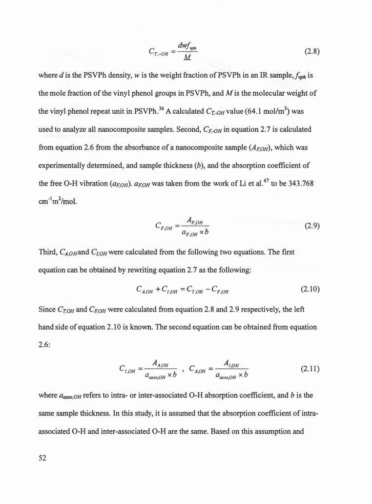
dwfvph cr.-on = M (2.8)
where d is the PSVPh density, w is the weight fraction of PSVPh in an IR sample,/vph is
the mole fraction of the vinyl phenol groups in PSVPh, and Mis the molecular weight of
the vinyl phenol repeat unit in PSVPh.36 A calculated Cr,-0n value (64.1 mol/m3) was
used to analyze all nanocomposite samples. Second, CF.-OH in equation 2.7 is calculated
from equation 2.6 from the absorbance of a nanocomposite sample (AF.on), which was
experimentally determined, and sample thickness (b), and the absorption coefficient of
the free 0-H vibration (aF.on). aF.oH was taken from the work of Li et al.47 to be 343.768
C - AF.OH F,OH -
aF OH x b '
Third, CA,onand C1,onwere calculated from the following two equations. The first
equation can be obtained by rewriting equation 2.7 as the following:
(2.9)
(2.10)
Since Cr,on and CF.on were calculated from equation 2.8 and 2.9 respectively, the left
hand side of equation 2.10 is known. The second equation can be obtained from equation
2.6:
C - AA,OH AIOH J OH - ---- ' CA OH = '
a asso,OH X b ' a asso,OH X b (2.11 )
where aas&o,OH refers to intra- or inter-associated 0-H absorption coefficient, and b is the
same sample thickness. In this study, it is assumed that the absorption coefficient of intra
associated 0-H and inter-associated 0-H are the same. Based on this assumption and
52

equation 2.11, the ratio of C1,0n to CA.OH is equal to the ratio of AA.OH to A1,0n, and this
relation is expressed as the following:
C1 0H A/ OH -'- = -·-cA,OH AA.OH
(2.12)
Since AA.OH and A1,0H were experimentally determined, the ratio of A1,on to AA.OH are also
known values. From equation 2.10 and 2.12, CwH and CA.OH can be determined. Finally,
the ratio ofCF,OH (equation 2.9), CA,oH, and C1,0H (equation 2 .10 and 2.12) to Cr,oH
( equation 2.8) were calculated. However, it should be noted that the calculated CA,oH and
C1,0H values cannot be taken as absolute values since it was assumed that the absorption
coefficients of intra- and inter-associated OH vibration are identical, an assumption that
has not been verified. 36 These values, however, could be used to compare the relative
amounts of intra- or inter-associated OH in the nanocomposite samples in this study.
The absorbance of each OH vibration in the nanocomposites was determined
from the IR peaks. The free, intra-associated, and inter-associated 0-H peaks were
deconvoluted using Peak.fit software (v 4.12). The position and width of the free OH and
intra-associated OH peaks were fixed with the peak position and width determined from
the PSVPh sample. However, the position and width of inter-associated OH peak were
allowed to float in the fitting procedure.
Figure 2.15 shows an example of the peak-fitted curves of the MM_Oxidized
nanocomposite IR data. Table 2.2 shows the summary of the curve-fitting results for the
nanocomposites prepared from the three different sample preparation processes with
oxidized or unoxidized MWNTs. Additionally, Figure 2.16 (a) and (b) show the ratio of
concentration of free (CF,oH), intra-associated (CA,oH) and inter-associated (C1,0H) OH
53

0.025
0.02
� 0.015
� 0.01
0.005
0 3100 3200 3300 3400 3500 3600
Wavenumber (cm-1 )
Figure 2.15 Example of peak-fitted curves of a MM_Oxidized nanocomposite.
54
3700

V'I V'I
Table 2.2 Summary of peak-fitting results for nanocomposites from three different sample preparation procedures.
Free OH Intra-associated OH Inter-associated OH
v• Arna v• AA.oH v• A1,0H CF,OH (cm·1) W112• (c�-1) CF,OH (cm·1) W112• (cm"1) CA.OH (cm·1) Win (cm·1) C1,0H /CT,OH
3546 27.5 0.67 4.98 3432 103 6.04 49.5 3240 72.8 1 . 1 8 9.66 0.078 MM_ Oxidized ± 0.02 ± 0.05 ± 0.05 ± 2 ± 0.04 ± 0.0 1 ± 0.003
3546 27.5 1 .44 10.7 3432 103 -6.39 50.8 3221 45.7 0.32 2.55 0. 167 MM_Unoxidized ± 0.02 ± 0.05 ± 0.05 ± 2 ± 0.04 ± 0.ol ± 0.005
3546 27.5 0.83 6. 17 3432 103 5.27 54.4 3236 43 .5 0.34 3.5 1 0.096 SCM _ Oxidized ± 0.02 ± 0.05 ± 0.05 ± 2 . ± 0.04 ± 0.02 ± 0.003
3546 27.5 2.35 17.5 3432 103 8.57 43.7 3223 55.2 0.57 2.91 0.272 SCM_ Unoxidized ± 0.04 ± 0. 1 ± 0.08 ± 2 ± 0.o? ± 0.02 ± 0.008
3546 27.5 0.97 7.21 3432 103 5.47 52.0 3236 52.6 0.5 1 4.85 0. 1 12 SCD _ Oxidized ± 0.02 ± 0.05 ± 0.05 ± 2 ± 0.04 ± 0.01 ± 0.004
3546 27.5 1 .86 1 3 .8 3432 103 9.86 46.7 3236 55.9 0.74 3 .5 1 0.216 SCD _Unoxidized ± 0.04 ± 0. 1 ± 0.08 ± 2 ± 0.06 ± 0.01 ± 0.007
* Values were fixed during curve-fitting.
CA.OH C1,0H /CT,OH /CT,OH
0.77 0. 1 5 1 ± 0.04 ± 0.005
0.79 0.039 ± 0.04 ± 0.001
0.85 0.055 ± 0.04 ± 0.002
0.68 0.045 ± 0.03 ± 0.00 1
0.8 1 0.076 ± 0.04 ± 0.002
0.73 0.055 ± 0.04 ± 0.002

0.9
0.8
0.7
0.6
0.5
0.4
0.3
0.2
0. 1
0
0.9
0.8
0.7
0.6
0.5
0.4
0.3
0.2
0. 1
0
(a)
CF,0H/C1,0H
CF,oH/Cr,oH
MM
• scM
D SCD
MM
• scM
D SCD
Figure 2.16 The ratio of concentration of free (CF,OH), intra-associated (CA,oH) and interassociated (C1,0H) to that of total OH (Cr,oH) vibration for nanocomposites with (a) oxidized and (b) unoxidized MWNTs.
56

vibration to that of total (Cr,oH) OH vibration in the nanocomposites with (a) oxidized
and (b) unoxidized MWNTs. As can be seen in Table 2.2 and Figure 2.16 (a), the amount
of inter-associated OH is highest for the melt-mixed nanocomposites with oxidized
MWNTs. Additionally, the free and intra-associated OH is lowest for the melt-mixed
nanocomposites with oxidized MWNTs. This suggests that the melt-mixing is most
effective at the formation of intermolecular hydrogen bonding between MWNTs and
polymers.
To correlate the results of IR analysis with the mechanical properties of
nanocomposites, the E' ratio of MM, SCM, or SCD samples with oxidized or unoxidized
MWNTs is plotted as a function of the ratio of C1,0H to Cr.OH as shown in Figure 2.1 7. E'
was estimated by averaging the E' ratio of each nanocomposite over - 60 °C < T -T g < -
40 °C. As can be seen in Figure 2.17, the highest E' ratio is present in the melt-mixed
nanocomposite with oxidized MWNTs, which correlates to the most inter-associated OH.
This data suggests that the higher modulus of the melt-mixed nanocomposites may be
correlated to the formation of more intermolecular hydrogen bonding than in solution
cast nanocomposites. More specifically, melt-mixing appears to be a very effective
sample preparation procedure to optimize the formation of intermolecular interactions
between MWNTs and polymers, and thus leads to improved mechanical properties of the
final polymer carbon nanotube nanocomposites. Additionally, when the E' ratio of the
nanocomposites with oxidized or unoxidized MWNTs prepared by identical sample
preparation procedures are compared, the E' ratio of the nanocomposites with oxidized
MWNTs is higher than that of nanocomposites with unoxidized MWNTs. This also
suggests that the formation of more intermolecular hydrogen bonding leads to improved
57

1 .25
1.2 -
1. 15 -� � 00 1. 1 �
- � S 1.05 -0 Q
� 1 -
0.95 -
0.9 -
0.85 0.02
� MM_Unoxidized
•
� SCM Oxidized
•
SCM Unoxidized
• <E-- SCD _ Oxidized
• � SCD Unoxidized
I I I I
0.04 0.06 0.08 0. 1 0. 12 C 1,oH/Cr,oH
•
i MM Oxidized
I
0. 14 0. 16
Figure 2. 17 Storage modulus ratio ( +) of MM, SCM, or SCD samples with oxidized or unoxidized MWNTs normalized to that of the PSVPh as a function of the ratio of concentration of inter-associated (Ci,oH) to that of total OH (Cr,oH) vibration.
58
mechanical properties of the nanocomposites.
2.3 Conclusions
In this study, the impact of sample preparation processes on polymer CNT
nanocomposites was examined by measuring the dynamic mechanical properties of
PSVPh/MWNT nanocomposites, and quantifying the extent of intermolecular hydrogen
bonding between the MWNTs and the polymers with IR. The DMA data suggests that
melt-mixing leads to more stable state of the nanocomposite morphology, which maybe
due to the "wrapping" of MWNTs with-polymers during processing at high temperature,
which is not observed for solution casting. Additionally, DMA data suggests that melt
mixing results in more improvement of the mechanical properties of the nanocomposite
than solution casting. Furthermore, the IR data analysis shows that the melt-mixing forms
more intermolecular hydrogen bonding. Therefore, this study can be used as a guideline
to achieve improved morphologies and properties of polymer carbon nanotube
nanocomposites by optimizing intermolecular interactions between nanotubes and
polymers using processing.
59

CHAPTER 3
SEQUESTERING SURFACE-MODIFIED GOLD NANOP ARTICLES IN DIBLOCK COPOLYMERS: STARTING MATERIALS
3.1 Experimental
3.1.1 Synthesis of Thiol-terminated Polystyrene
Thiol-terminated polystyrene (PS-SH) with low molecular weight was
synthesized starting with bromine-terminated polystyrene (PS-Br), which was
synthesized via ATRP, followed by thiolation of PS-Br to PS-SH. This synthesis
procedure was developed to modify the process reported by Garamszegi et al. 48 All
chemicals in this reaction were purchased from Aldrich, and used as received. In a typical
procedure for the synthesis for PS-Br, styrene (monomer, 10 g, 96 mmol, 4.8 equiv.),
copper (I) bromide (CuBr, catalyst, 2.869 g, 20 mmol, 1 equiv.), 1-phenylethyl bromide
(1-PEBr, initiator, 3.7014g, 20mmol, 1 equiv.), N,N,N' ,N' ,N'
pentamethyldiethylenetriamine (PMDETA, ligand, 6.932g, 40mmol, 2 equiv.) and
anhydrous THF (solvent, 10 g) were added to a 100 ml two-neck, round-bottom flask. All
reactants were degassed through freeze-thaw processes that were repeated five times. The
polymerization was conducted under argon in an oil bath at 110 °C for 90 min. After
polymerization, the polymers were purified by dissolving in THF and precipitating in
cold methanol. This process was repeated three times. The resultant polymers were then
dried under vacuum at 50 °C for 24 hrs. The purified polymers were characterized by
GPC to measure molecular weight and by NMR for end group analysis.
The thiolation of PS-Br was conducted to convert the bromine-end groups to
60
thiol-end groups. In a typical thiolation reaction, PS-Br (1 g, 0.89 mmol, 1 equiv.) was
completely dissolved in 30 ml ofDMF, and thiourea (0.68 g, 8.9 mmol, 10 equiv.) was
then added to this polymer/DMF solution. This mixture was stirred under argon at 100 °C
for 24 hrs. NaOH (sodium hydroxide, 0.36 g, 8.9 mmol, 10 equiv.) dissolved in 2.9 ml of
water was then added, and this mixture was heated at 110 °C for another 24 hrs. Seven
drops of95 % sulfuric acid mixed with 1.8 ml of water were added and this mixture was
stirred at room temperature for an additional 5 hrs. The polymers were then purified by
dissolving in THF and precipitating in cold methanol and repeated twice. The final
product was dried under vacuum at 50 °C for 24 hrs. The dried polymers were
characterized by GPC and by NMR to verify the conversion of bromine end groups to
thiol end groups. Figure 3 .1 shows the scheme for the synthesis procedure for PS-SH
starting with PS-Br.
3.1.2 Synthesis of Polystyrene-coated Gold Nanoparticles
Gold nanoparticles with surfaces that are coated with low molecular weight
polystyrene (PS-coated Au nanoparticles) were synthesized by utilizing thiol-terminated
polystyrene (PS-SH) as a stabilizing ligand during the synthesis. The success of this
. reaction is based on the fact that "a thiol ligand strongly binds gold due to the soft
character of both Au and S.',49 This synthesis procedure was developed to mimic the
process reported by Brust et al.50 and Bockstaller et al.,38•5 1 which is a two-phase
synthesis procedure. In this reaction, hydrogen tetrachloroaurate(III) hydrate, sodium
borohydride, and tetraoctylammonium bromide were purchased from Sigma-Aldrich, and
used as received. An aqueous solution of hydrogen tetrachloroaurate (HAuCl43H20, 35.4
61

DMF
1 NaOH SH
Figure 3.1 Scheme for synthesis procedure of PS-SH48
62

mg in 3 ml water, 30 mmol/L) was mixed with a solution of tetraoctylammonium
bromide in toluene (N(CsH11)4Br, 218.7 mg in 8ml toluene, 50 mmol/L), which is a phase
transfer agent in this reaction.5 1 This mixture was vigorously stirred for 3 hrs until the
tetrachloroaurate was completely transferred from the aqueous phase to the toluene layer,
which can be verified by the appearance of the yellowish color of the toluene layer. The
organic phase was separated from the two-phase (water/toluene) system. PS-SH (150 mg,
0.1 mmol) was then added to the separated toluene layer. An aqueous solution of sodium
borohydride (NaB�, 37.8g in 2.5ml water, 0.4 mol/L), which is a reducing agent in this
reaction, was gradually added while this mixture was vigorously stirring. 5 1 With the
addition of sodium borohydride, a color change of the solution was observed from yellow
to red-wine. This mixture was stirred for 3 hrs, and the organic phase was then separated.
This separated solution was evaporated to 1 ml using a rotary evaporator. The final
product was precipitated in a mixture of methanol and ethanol (1 : 1 in volume ratio), and
the dark brown product was filtered. 38 Any unbound PS-SH ligands were removed by
washing with a mixture of ethanol and THF ( 5 : 1) several times. 38 The final PS-coated
gold nanoparticles were dried under vacuum at 70 °C for 24 hrs.
3.1.3 Transmission Electron Microscopy (TEM) of Gold Nanoparticles
The prepared gold nanoparticles were characterized by transmission electron
microscope (TEM, Hitachi H800) with an acceleration voltage of 100 Ke V. To examine
the PS-coated gold nanoparticles by TEM, a dilute solution of the gold nanoparticles in
toluene ( 5 mg/ml) was prepared. One drop of this solution was placed on porous carbon
films supported by copper grids. so These films were dried in air to evaporate the solvent.
63

3.1.4 Synthesis of Bromine-terminated Poly(styrene-co-acetoxystyrene) Copolymers, and their Hydrolysis or Thiolation
In this study, the synthesis of thiol-terminated poly(styrene-co-vinyl phenol)
copolymers (PSVPh-SH) was first attempted starting with synthesizing bromine
terminated poly( styrene-co-acetoxystyrene) copolymers via ATRP, and followed by
hydrolysis or thiolation. In the synthesis of bromine-terminated poly(styrene-co
acetoxystyrene) copolymers, styrene (monomer, 8.6 g, 82 mmol, 4.1 equiv.), 4-
acetoxystyrene (monomer, 2.2 g, 13 mmol, 0.67 equiv.), 1-phenylethylbromide (1-PEBr,
initiator, 3.7 g, 20 mmol, 1 equiv.), copper (I) bromide (CuBr, catalyst, 2.9 g, 20 mmol, 1
equiv.), N,N,N' ,N' ,N"-pentamethyldiethylenetriamine (PMDETA, ligand, 6.9 g, 40 mmol,
2 equiv.), and anhydrous THF (solvent, 10.8 g) were added to two-neck, round bottom
flask. All reactants were degassed by freeze and thaw repeated 3 times. Polymerization
was then conducted in an oil bath at 110 °C for 90 mins. After 90 mins, polymers were
purified by precipitating in cold methanol three times. Final products were filtered, and
dried under vacuum at 7 5 °C for 24 hrs.
Additionally, hydrolysis of bromine-terminated poly( styrene-co-acetoxystyrene)
copolymers was conducted as follows: 1 g of bromine-terminated poly(styrene-co
acetoxystyrene) copolymers was completely dissolved in 10 ml of dioxane, and 3 g of
hydrazine hydrate was added to this polymer/dioxane solution. This mixture was stirred
for 48 hrs at room temperature. Polymers were then precipitated in cold methanol, and
dried under vacuum at 85 °C for 24 hrs.
Finally, thiolation of bromine-terminated poly(styrene-co-acetoxystyrene)
copolymers was conducted as follows: 1 g of bromine-terminated poly(styrene-co-
64

acetoxystyrene) was completely dissolved in 30 ml of DMF. Thiourea (0.48 g, 6.3 mmol,
10 equiv.) was added to this polymer/DMF solution, and this mixture was stirred at 110
°࿁C for 24 hrs. Five drops of 95 % sulfuric acid in 1.3 ml of water were then added, and
this mixture was stirred at room temperature for an additional 5 hrs. The polymers were
purified by precipitating in cold methanol repeated twice. Final products were dried
under vacuum at 75 °C for 24 hrs.
3.1.5 Synthesis of Thiol-terminated Poly(styrene-co-vinyl phenol) Copolymers
The synthesis of thiol-terminated poly(styrene-co-vinyl phenol) (PSVPh-SH)
copolymers was attempted by first synthesizing bromine-terminated poly(styrene-co-4-
tert-butoxystyrene) copolymers via ATRP, followed by the thiolation of the copolymers to
thiol-terminated poly(styrene-co-4-tert-butoxystyrene) copolymers, and the subsequent
hydrolysis of the thiol-terminated poly(styrene-co-4-tert-butoxystyrene) to PSVPh-SH.
Figure 3.2 shows the proposed scheme for the synthesis for thiol-terminated poly(styrene
co-vinyl phenol) copolymers. In a typical synthesis of the bromine-terminated
poly(styrene-co-4 ... tert-butoxystyrene), styrene (23.9 g, 230.4 mmol, 3.8 equiv.), 4-tert
butoxystyrene (10.2 g, 57.6 mmol, 0.96 equiv.), copper (I) bromide (8.6 g, 60 mmol, 1
equiv.), 1-phenylethyl bromide (1-PEBr) (11.1 g, 60 mmol, 1 equiv.), N,N,N' ,N' ,N"
pentamethyldiethylenetriamine (PMDETA) (20.8 g, 120 mmol, 2 equiv.), and anhydrous
THF (34.2 g) were added to a two-neck, round bottom flask. All reactants were degassed
by freeze-thaw techniques repeated 7 times. The polymerization was conducted under
argon in an oil bath at 110 °C for 90 mins. After 90 mins, the flask was immediately
65

Br
SH
Thiourea/DMF
NaOH
HCI Dioxane
SH
OH
Figure 3.2 Scheme for synthesis procedures for thiol-terminated poly(styrene-co-vinyl phenol) copolymers starting with bromine-terminated poly(styrene-co-4-tertbutoxystyrene) copolymers.
66

opened, and the polymers were precipitated in cold methanol. The final product was
filtered, and dried under vacuum at 50 °C for 24 hrs. The polymers were then
characterized by GPC to determine molecular weight properties and by NMR to analyze
the composition and verify the end capping of the copolymer.
The thiolation of the bromine-terminated poly(styrene-co-4-tert-butoxystyrene)
copolymers was conducted by the following procedure: bromine-terminated poly(styrene
co-4-tert-butoxystyrene) (0.29 g, 0.21 mmol, 1 equiv.) was completely dissolved in 8.7
ml ofDMF, and thiourea (0.16 g, 2.05 mmol, 10 equiv.) was then added into this
polymer/DMF solution. This mixture was vigorously stirred under argon at 100 °C for 24
hrs. NaOH (0.082 g, 2.05 mmol, 10 equiv.) dissolved in 0.7 ml of water was then added,
and this mixture was stirred at 110 °C under argon for 24 hrs. Two drops of 95 % sulfuric
acid in 0.41 ml water were added, and this mixture was stirred at room temperature for an
additional 5 hrs. The polymers were precipitated in cold methanol, and filtered. Final
polymer products were dried under vacuum at 50 °C for 24 hrs. After thiolation, polymers
were characterized by GPC, and by NMR to confirm the conversion of bromine-end
groups to thiol-end groups.
The hydrolysis of the thiol-terminated poly(styrene-co-4-tert-butoxystyrene)
copolymers was developed from the work reported by Asari et al. 52, where the synthesis
procedures are: 70 mg of thiol-terminated poly(styrene-co-4-tert-butoxystyrene) was
completely dissolved in dioxane, and this polymer solution was kept under argon for 15
mins at 80 °C. Five drops of cone. hydrochloric acid (HCl) was added to this mixture, and
it was stirred under argon for 30 mins. The polymers were then precipitated in cold
methanol, and filtered. Final products were dried under vacuum at 50 °C for 24 hrs. After
67

hydrolysis, the polymers were characterized by GPC,' and by NMR to analyze thiol-end
groups and to confirm the conversion of tert-butoxy groups to hydroxyl groups.
3.2 Results and Discussion
3.2.1 Bromine-terminated Polystyrene
Atom transfer radical polymerization (ATRP) is a controlled free radical
polymerization.43 In a typical ATRP reaction, a halogen atom at the end of a polymer is
transferred to a Cu(I) complex to allow the reaction with monomer to grow the polymer
chain, and the halogen atom can also return to the polymer chain end to limit radical
concentration, and thus termination. 43•48 Thus, polymers, at which end a halogen atom
exists, with controlled polydispersities can be synthesized via ATRP.43•48 In this study,
bromine-terminated polystyrene with low polydispersity was synthesized by ATRP. The
molecular weight characteristics of bromine-terminated polystyrene (PS-Br) was found to
have an Mn of 1,100 g/mol, Mw of 1,300 g/mol, and PDI of 1.18. This GPC data
indicates that the molecular weight of polymers can be controlled by manipulating the
ratio of monomer, catalyst, initiator, and ligand and by adding solvent (THF in this study)
in ATRP. Specifically, the ratio, 4.8: 1: 1: 2 of monomer (styrene, 4.8 equiv.), catalyst
(CuBr, 1 equiv.), initiator (1-PEBr, 1 equiv.) and ligand (PMDETA, 2 equiv.) and the
same amount of solvent as that of monomers provide low molecular weight of polymers
and low polydispersity.
These experimental results were obtained as the following: first, the amount of
monomers, initiator, catalyst, and ligand to synthesize bromine-terminated polystyrene
with a target molecular weight (Mn) of 1,000 g/mol was calculated based on the fact that
68

the average degree of polymerization (DP) of polymers synthesized by living
polymerization is the ratio of concentration of monomers to the concentration of initiators.
That is, DP in a living polymerization is
DP = [M]o [I]o
(3. 1 )
where [M]o is the concentration of monomers, and [1]0 is the concentration of initiators.43
More specifically, to obtain an Mn of 1 ,000 g/mol (DP = 9.6) of polystyrene, the expected
mole ratio ofmonome�s to initiators is 9.6 to 1 based on the equation 3. 1 . Therefore, the
ratio, 9.6: 1 : 1 : 2 of monomers, initiators, catalysts, and ligands was first utilized in ATRP.
This ratio of initiator, catalysts, and ligands, 1 : 1 : 2, was developed to mimic the process
reported by Garamszegi et al. 48 The molecular weight of polystyrene in this first attempt
was found to have an Mn of 3,500 g/mol, Mw of 5, 100 g/mol, and PDI of 1.45. These
molecular weight properties and polydispersity were higher than what was expected from
the stoichiometric calculation. Therefore, to reach the target molecular weight of
polystyrene via ATRP, the amount of initiators, catalysts, and ligands was doubled
keeping the amount of monomers same. That is, the ratio, 4.8: 1 : 1 : 2 of monomers,
initiators, catalysts, and ligands were utilized in this second attempt. The molecular
weight of this polymer was found to have an Mn of 3,100 (g/mol), Mw of 5,100 (g/mol)
and PDI of 1.65. This molecular weight is still higher than the target molecular weight
( 1 ,000 g/mol). Finally, solvent (anhydrous THF) with the same amount of monomers was
added to the reactants with the ratio of 4.8: 1 : 1 : 2 of monomers, initiators, catalysts, and
ligands. The molecular weight of polymer in this third attempt was found to have an Mn
of 1 , 100 g/mol, Mw of 1 ,300 g/mol, and PDI of 1. 18. This molecular weight of the
69

polymers is close to the target molecular weight (1,000 g/mol). Therefore, these
experimental results provide a guideline to synthesize low molecular weight polymers by
ATRP.
Additionally, NMR was utilized to analyze the bromine-end groups of the PS-Br.
Figure 3.3 shows the 1H spectrum of the bromine-terminated polystyrene dissolved in
deuterated chloroform. As can be seen in Figure 3.3, "the methine proton next to the
bromine chain end has a chemical shift of 4.45 - 4.75 ppm,"48 which indicates that the
bromine group at the end of the polymer chain exists.
3.2.2 Thiol-terminated Polystyrene
The molecular weight of thiol-terminated polystyrene (PS-SH) was also
determined using a PC-GPC 120, and was found to have an Mn of 1,500, Mw of 1,800
and PDI of 1.20. Additionally, NMR was utilized to analyze thiol-end groups of the PS
SH. Figure 3.4 shows the 1H spectrum of the thiol-terminated polystyrene dissolved in
deuterated chloroform. As can be seen in Figure 3.4, the methine proton next to the thiol
end groups has a chemical shift of 3 .0 - 3 .3 ppm, and the methine proton next to the
bromine chain ends, as shown in Figure 3.3, disappears. This NMR data indicates that the
conversion of the bromine-end groups to thiol-end groups was successful.
3.2.3 Polystyrene-coated Gold Nanoparticles
TEM is a useful tool to characterize the size distribution of nanoparticles. The
primary contrast mechanism of TEM is based on the difference of electron density from
different atoms. 53 The atoms of metal or semiconductor nanoparticles have much higher
70

a
t 4
c_) t I . ,
C b ---CH-----1CH2--QH--Br
�
C J \ �
�J \_ _ ;J V
b
-...ii"il . •;i-- � -- - -.-.......,.����....... piMdt iilc e a ; a • s • ' t
Figure 3.3 1H spectrum of bromine-terminated polystyrene dissolved in deuterated chloroform .
,,.

'-l N
C b
---CH----aCH2--CH--S H
a
a
C
l N'
• , ' 1 .. J I
Figure 3.4 1H spectrum of thiol-terminated polystyrene dissolved in deuterated chloroform.
I I
J
* ,...

electron density than atoms of polymers. Thus, it is possible to obtain images of
distribution of nanoparticles dispersed in polymers, which can be identified as dark spots
in TEM images.5 1 Additionally, a real space image can be obtained directly by TEM.5 1 In
this study, the polystyrene-coated gold nanoparticles were characterized by TEM to
analyze the size and size distribution of the gold nanoparticles. Figure 3.5 shows the
TEM images of the PS-coated gold nanoparticles synthesized in this project. Additionally,
Figure 3.6 shows the size and size distribution of the gold nanoparticles, which were
determined using Image J software (1 .34 s) by counting 139 particles, and an average
diameter was determined from this data to be 6.5 nm with standard deviation of 2.8. As
can be seen Figure 3.5 and 3.6, the size of gold nanoparticles was controlled with the
presence of thiol-terminated polystyrene, as it prevents the aggregation of gold
nanoparticles. 1 5
3.2.4 Attempt for Synthesis of Thiol-terminated Poly(styrene-co-vinyl phenol) Copolymers Starting with Bromine-terminated Poly(styrene-co-acetoxystyrene) Copolymers
In this study, the synthesis of thiol-terminated poly(styrene-co-vinyl phenol)
copolymers was first attempted starting with bromine-terminated poly(styrene-co
acetoxystyrene) copolymers. Bromine-terminated poly( styrene-co-acetoxystyrene)
copolymers were synthesized via ATRP, and both the hydrolysis and the thiolation of the
copolymers were separately attempted. The molecular weight of the bromine-terminated
poly(styrene-co-acetoxystyrene) copolymers was found to have an Mn of 1 ,600, Mw of
2,000, and PDI of 1.25. The bromine-end group and acetoxystyrene group of the
copolymers were characterized by NMR. NMR data of bromine-terminated poly(styrene-
73

• • � ,· I' • • • • • • •
• • • •
• • • .. • ., • • • • • • • •
• • • • • • • • . • • • • •• • ,
• • • • • • • ' • • " " • • •
• • •
,. • • •• • . .
• • • • ' I
•
• .. • • • ' '
• • • ..
.c • • • • • • • .. Figure 3.5 Representative TEM image of PS-coated gold nanoparticles. (Scale bar size: 100 nm)
74

30
25
20
1 5
1 0
5
0 0 4 5 6 7 8 9 9 10 1 1 12
Diameter (nm)
Figure 3.6 Size and size distribution of PS-coated gold nanoparticles.
75

co-acetoxystyrene) copolymers shows that the methine proton next to the bromine-end
group has a chemical shift of 4.45 - 4. 75 ppm, which indicates the existence of bromine
end groups. NMR data of the copolymers shows that the 3 methyl protons of acetoxy
groups have a chemical shift of 2.2 -2.4 ppm. Also, NMR data provides the mole
fraction of acetoxystyrene groups of 22.6 %.
The hydrolysis of bromine-terminated poly(styrene-co-acetoxystyrene)
copolymers was attempted to convert the acetoxy groups to hydroxyl groups keeping the
bromine-end group. After hydrolysis, the molecular weight of the hydrolyzed polymers
was found to have an Mn of2, I00, and Mw of2,700, and PDI of 1.29. Additionally,
NMR was utilized to analyze the bromine-end groups and to confirm the conversion of
the acetoxy groups to hydroxyl groups. NMR data shows that the peak of the 3 methyl
protons of the bromine-terminated poly(styrene-co-acetoxystyrene) copolymers at 2.2 -
2.4 ppm disappeared, which suggests the conversion of the acetoxy groups to hydroxyl
groups. However, NMR data shows that clearly observed peaks of the methine proton
next to the bromine-end group of the bromine-terminated poly(styrene-co
acetoxystyrene) copolymers become very weak after hydrolysis. This indicates that the
hydrolysis using hydrazine hydrate alters the bromine-end groups, and may result in loss
of the bromine-end groups. It was recognized that few bromine-end groups were not
enough to create thiol-end groups.
The thiolation of the bromine-terminated poly( styrene-co-acetoxystyrene)
copolymers was also attempted to convert the bromine-end groups of the copolymers to
thiol-end groups while keeping the acetoxy groups. NMR was utilized to confirm the
conversion of bromine-end groups of the copolymers to thiol-end groups, and to analyze
76

the acetoxy groups of the copolymers.
In the NMR data of the copolymers after thiolation, the peak of the methine
proton next to the thiol-end group at 3.0-3.2 ppm was rarely observed. Additionally, a
weak peak of the methine proton next to the bromine-end group was observed although
the thiolation was conducted. This NMR data indicates that the thiolation of the bromine
terminated poly( styrene-co-acetoxystyrene) copolymers using thiourea was not
successful, and may result in loss of the bromine-end groups of the copolymers.
Additionally, NMR data shows that peaks of 3 methyl protons of the acetoxy groups in
the bromine-terminated copolymers unexpectedly disappeared after thiolation, which
indicates that the acetoxy groups of the bromine-terminated copolymers may be lost
during thiolation. This NMR data suggests that acetoxy styrene groups, which have ester
bonds, are not stable during thiolation using hydrazine hydrate and NaOH.
NMR data of the bromine-terminated poly( styrene-co-acetoxy styrene)
copolymers after hydrolysis or thiolation suggests that bromine-terminated poly( styrene
co-acetoxystyrene) copolymers may not be appropriate as starting materials to synthesize
thiol-terminated poly(styrene-co-vinyl phenol) copolymers. Therefore, in this study, the
synthesis of thiol-terminated poly(styrene-co-vinyl phenol) copolymers was attempted
starting with bromine-terminated poly(styrene-co-4-tert-butoxystyrene) copolymers,
followed by thiolation and hydrolysis, which was selected in that the ether bonds of the
tert-butoxystyrene groups may be more stable under thiolation than the ester bonds of the
acetoxystyrene groups.
77

3.2. 5 Bromine-terminated Poly(styrene-co-4-tert-butoxystyrene) Copolymers
The molecular weight of the bromine-terminated poly(styrene-co-4-tert
butoxystyrene) copolymers was determined by PL-GPC and to have an Mn of 1,412, Mw
of 1,685, and PDI of 1.19. Additionally, NMR was utilized to analyze the bromine-end
groups and composition of the copolymer. Figure 3. 7 shows the 1 H spectrum of the
bromine terminated poly(styrene-co-4-tert-butoxystyrene) copolymers dissolved in
deuterated dioxane. As can be seen, the methine proton next to the bromine end group has
a chemical shift of 4.45 -4.75 ppm. This data indicates the presence of the bromine-end
group of the copolymer. Additionally, based on the integration of proton groups, the
composition of the copolymer was determined by analysis of these spectra. In this
analysis, the mole fraction of styrene groups is set to x, and fraction of tert-butoxystyrene
groups y. Based on the presence of 5 aromatic protons in each styrene group and 4
aromatic protons in each butoxystyrene group, the equation 5x + 4y = 9 .21 is valid, where
9.21 is the area of the aromatic (6.2-7.6 ppm) peaks in the NMR curve. Additionally, the
integration of the 9 methyl protons in the tert-butoxy groups, which occurs 1.2 -1.4
ppm, 54 provides the relationship 9y = 1. Solving these 2 equations leads to the result that
the mole fraction of tert-butoxystyrene in the copolymer is 5.9 %.
3.2. 6 Thiol-terminated Poly(styrene-co-4-tert-butoxystyrene) Copolymers
The molecular weight of the thiol-terminated poly(styrene-co-4-tert
butoxystyrene) copolymers was determined by GPC, and found to have an Mn of 1,900
g/mol, Mw of 2,700 g/mol, and PDI of 1.42. Additionally, NMR was utilized to confirm
78
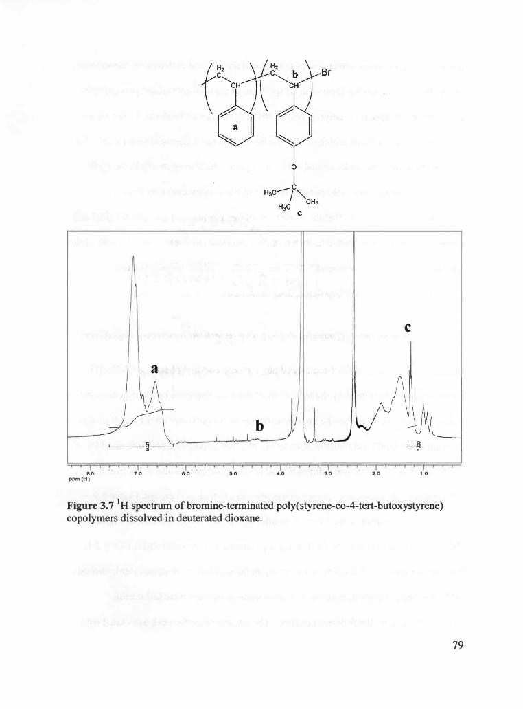
' i I ' · i I ' l 8.0 7.0
ppm (t1 )
a
I ( . ' . . I I f I 6.0 5.0
b
I I I . '4.0
I, I I . 3.0 .
I I I 2.0
C
I I 1 .0
Figure 3. 7 1 H spectrum of bromine-terminated poly( styrene-co-4-tert-butoxystyrene) copolymers dissolved in deuterated dioxane.
79

the conversion of bromine-end groups to thiol-end groups, and to determine the success
of this reaction. Figure 3.8 shows the 1H spectrum of the thiol-terminated poly(styrene
co-4-tert-butoxystyrene) copolymers dissolved in deuterated chloroform. As can be seen
in Figure 3.8, the methine proton next to the thiol group has a chemical shift of 2.9-3.2
ppm. Additionally, the peaks around 4.45 -4.75 ppm, which were shown in the NMR
data of the bromine-terminated poly(styrene-co-tert-butoxystyrene) copolymers,
disappeared. This indicates that the conversion of the bromine-end group to the thiol end
group occurred upon thiolation of the bromine-terminated polymers. Also, the peak of the
tert-butoxy group protons around 1.2 -1.4 ppm indicates there remains the tert
butoxystyrene group in the copolymer after thiolation.
3.2. 7 Hydrolysis of Thiol-terminated Poly(styrene-co-tert-butoxystyrene) Copolymers
The synthesis of thiol-terminated poly(styrene-co-vinyl phenol) (PSVPh-SH)
copolymers was attempted by the hydrolysis of the thiol-terminated poly(styrene-co-tert
butoxystyrene) copolymers. The molecular weight of the polymers after hydrolysis was
determined by GPC, and found to have an Mn of 2,700 g/mol, Mw of 4,300, and PDI of
1.60. Additionally, NMR was utilized to analyze thiol-end groups and to confirm the
conversion of the tert-butoxy groups of the polymers to hydroxyl groups. Figure 3.9
shows the 1H spectrum of the copolymers after hydrolysis. As can be seen in Figure 3.9,
the methine proton next to the thiol end group remains at a chemical shift of 2.9 -3 .1
ppm, which indicates that the thiol end group in the copolymers remains after hydrolysis.
NMR spectrum, however, suggests that some thiol-end groups were lost during
hydrolysis based on the following analysis. The integration of the peak associated with
80

a
b
,f
C
y !IJ d
I t . f i I I f j I I I I ' I I I 4.0
I I I 3.0
f ' ( I I 8.0 7.0
ppm (t1) 8.0 5.0 2.0
Figure 3.8 1H spectrum of thiol-terminated poly(styrene-co-tert-butoxystyrene) copolymers dissolved in deuterated chloroform.
1 .0
81

I I j f i ·i I j
8.0 7.0 ppm (t1 )
I ' 8.0
I I I 5.0
I I ' r ' I ' 4.0 3.0
y � 0
' I I ·' i j l i
2.0 1 .0
Figure 3.9 1H NMR spectrum of thiol-terminated poly(styrene-co-4-tert-butoxystyrene) copolymers dissolved in deuterated chloroform after hydrolysis.
82

the methine proton next to the thiol-end group provides a normalized value of z = 0.01.
This NMR data indicates that approximately 1 end group per 100 monomers exists, or
0.01 end group per every monomer. From the molecular weight data as determined by
GPC, it can be estimated that there should exist 1 thiol end group for every 30 monomers
if the thiolation was successful. This correlates to z = 0.03 end group per monomer. Thus,
this analysis suggests that some thiol end groups may be lost during the hydrolysis
experiment. However, given the uncertainty in this data, more careful experiments are
required to verify this interpretation of the data.
Additionally, the NMR spectrum shows that the 9 methyl protons in the tert
butoxy group at a chemical shift of 1.2 -1.4 ppm remain, which indicates that the tert
butoxy groups still remain after hydrolysis. Also, the integration of the 9 methyl protons
provide 9y = 0.40 by normalizing the integration of all aromatic protons 5. This value
(0.40) is close to the integration value of 9 methyl protons (0.39) of thiol-terminated
poly(styrene-co-tert-butoxystyrene) copolymers before hydrolysis, which indicates that
the conversion of the tert-butoxy group to the hydroxyl group was not successful in this
study.
It is recognized that this incomplete conversion of tert-butoxy group to hydroxyl
group may result of insufficient reaction time for the hydrolysis, which was only 30 mins
in this study. That is, this experimental result suggests that longer reaction time for the
hydrolysis may be necessary to improve the conversion of the tert-butoxy group to the
hydroxyl group. Additionally, the incomplete hydrolysis may be due to an insufficient
amount of HCl, which was only 5 drops in this study. However, from the NMR spectrum,
it should be noted that the hydrolysis using HCl in this study may impact the thiol-end
83

group of the poly(styrene-co-tert-butoxystyrene) copolymers. Therefore, in future work,
an efficient method to convert the tert-butoxy group to the hydroxyl group while the thiol
end group remains unchanged is demanded. That is, carefully controlled reaction time
and/or amount ofHCl in this hydrolysis may be needed.
3.3 Conclusions
In this study, the synthesis of the starting materials to investigate sequestering
surface-modified gold nanoparticles in diblock copolymers was attempted. Thiol
terminated polystyrene was synthesized starting with bromine-terminated polystyrene,
followed by thiolation. Gold nanoparticles coated with low molecular weight polystyrene
were synthesized by utilizing the thiol-terminated polystyrene as a stabilizing ligand. Our
results indicate that low molecular weight polymers with a halogen end group can be
obtained via ATRP. 1 H NMR spectrum shows that the thiolation of this bromine
terminated polystyrene was complete using thiourea and NaOH. The experimental results
in this study also show gold nanoparticles coated with polystyrene can be synthesized,
and the size of the gold nanoparticles can be controlled using this PS-SH as a stabilizing
ligand. Additionally, the synthesis of thiol-terminated poly(styrene-co-vinyl phenol)
copolymers was attempted starting with bromine-terminated poly(styrene-co-4-tert
butoxystyrene) copolymers, followed by thiolation and hydrolysis. Characterization
results by NMR show that the thiolation of the bromine-terminated poly(styrene-co-4-
tert-butoxystyrene) copolymers was essentially complete. The NMR spectrum also shows
that conversion of the tert-butoxy group to the hydroxyl group by hydrolysis, however,
was incomplete. NMR also indicates that the hydrolysis reaction may also result in the
84

loss of thiol end groups though more careful analysis is required to verify this. Increased
reaction time and amount of HCl in the reaction may improve the success of the
hydrolysis reaction but may impact on SH end group.
85

CHAPTER 4
CONCLUSIONS AND FUTURE WORK
This thesis presents experimental efforts to study the dispersion of nanoparticles
in a polymer matrix using intermolecular hydrogen bonding between the nanoparticles
and polymers for the purpose of controlling and realizing the tailored morphologies and
thus optimizing properties of the final nanocomposites under two main topics. The first
topic is the impact of sample preparation processes on the properties of polymer carbon
nanotube nanocomposites. In this study, nanocomposites composed of PSVPh
copolymers with 15 % mole fraction of vinyl phenol groups with either oxidized or
unoxidized MWNTs prepared by three different sample preparation processes. The
mechanical properties of the prepared nanocomposites were measured by DMA.
Additionally, the nanocomposites were analyzed by IR to quantify the extent of
intermolecular hydrogen bonding between the MWNTs and PSVPh, and to correlate the
mechanical properties of the nanocomposites to the extent of intermolecular interactions
between the MWNTs and PSVPh. The measured mechanical properties of the
nanocomposites suggest that melt-mixing leads to more stable morphologies of the final
nanocomposites than solution casting, which is probably due to the wrapping of the
MWNTs with polymer chains. Additionally, the IR analysis of the nanocomposites
indicates that melt-mixing can result in the formation of more intermolecular hydrogen
bonding between MWNTs and PSVPh than solution casting, and thus suggests that melt
mixing can lead to the more reproducible mechanical properties than solution casting.
Therefore, the DMA data and IR analysis suggest that melt-mixing is a very effective
86

method to prepare polymer carbon nanotube nanocomposites.
In this study, the properties of the MWNT /PSVPh nanocomposites and the
intermolecular hydrogen bonding between the MWNTs and PSVPh were studied with
identical MWNT and PSVPh systems. In future studies, it would be interesting to find the
optimum composition of the PSVPh copolymer that maximizes intermolecular hydrogen
bonding between the MWNTs and the PSVPh to realize optimum properties of the final
nanocomposites. More specifically, it would be useful to study the mechanical properties
of melt-mixed nanocomposites, which are composed of copolymers that contain O %
(polystyrene), 10 %, 20 %, 30 %, and 40 % mole fraction vinyl phenol with either
oxidized or unoxidized MWNTs, and to analyze the extent of intermolecular hydrogen
bonding between the MWNTs and each PSVPh composition. This study will provide
guidelines to maximize the intermolecular hydrogen boding between MWNTs and
PSVPh. Thus, this future study will provide information on the impact of the extent of
intermolecular interactions between MWNTs and PSVPh on the final morphologies of
melt-mixed nanocomposites, and the impact of the final morphologies on the ultimate
properties of the nanocomposites.
Additionally, in this study, the morphologies of nanocomposites were discussed
based on the mechanical properties of the nanocomposites. In a future study,
experimental studies that examine the dispersion of MWNTs in a PSVPh matrix would be
useful to connect the morphologies of nanocomposites to the mechanical properties of the
final nanocomposites. Microscopy studies of nanocomposites, such as optical microscopy
can provide direct evidence of the MWNTs dispersion in a polymer matrix, or SEM
provides images of the fracture surfaces of the nanocomposites and would be useful to
87

investigate the state of the nanocomposite morphologies in this future study.
The other topic is to synthesize starting materials to sequester surface-modified
gold nanoparticles in one phase of di block copolymer systems. The long term goal of this
project is to control the morphologies of the diblock copolymer nanocomposites, and thus
to realize the desired properties of the nanocomposites by investigating the impact of
enthalpic attractions between nanoparticles and polymer chains in one of the blocks of
the diblock copolymers on the nanocomposite structure. In this study, polystyrene-coated
gold nanoparticles (PS-coated gold nanoparticles) were synthesized using thiol
terminated polystyrene (PS-SH) as a stabilizing ligand. PS-SH was synthesized by
thiolation of bromine-terminated polystyrene (PS-Br), which was synthesized via ATRP.
TEM images show that PS-coated gold nanoparticles can be synthesized by using the PS
SH as a stabilizing ligand, and also show that the size of the gold nanoparticles can be
controlled with the PS-SH, which prevents the aggregation of gold nanoparticles.
Additionally, the synthesis of thiol-terminated poly(styrene-co-vinyl phenol)
copolymers (PSVPh-SH) was attempted. This synthesis was first attempted starting with
bromine-terminated poly(styrene-co-acetoxystyrene) copolymers, and followed by either
hydrolysis or thiolation of the copolymers. Our experimental results indicate that the
conversion of the acetoxy groups of the copolymer to hydroxyl groups and the
conversion of the bromine-end groups of this copolymer to thiol-end groups were not
successful. NMR data suggests that the hydrolysis of the copolymers using hydrazine
hydrate results in loss of end-groups of the copolymers, and the acetoxy groups of the
copolymers are not stable under thiolation using thiourea and NaOH.
Thus, the synthesis of PSVPh-SH was also attempted starting with a different
88
copolymer. This synthesis was attempted as follows: first, low molecular weight
poly(styrene-co-4-tert-butoxystyrene) copolymers with bromine-end groups were
synthesized via ATRP. Next, thiolation to convert to the end group of the copolymers to
thiols was attempted. Finally, hydrolysis to convert the tert-butoxy groups to hydroxyl
groups was attempted. Our NMR results indicate that the conversion of the bromine-end
groups to thiol-end groups by thiolation was complete. However, the conversion of the
tert-butoxy groups of the thiol-terminated poly(styrene-co-4-tert-butoxystyrene)
copolymers to hydroxyl groups was not successful. Furthermore, NMR data suggests that
the hydrolysis can impact the thiol-end group of the thiol-terminated copolymers. This
incomplete hydrolysis is probably due to short reaction time and/or insufficient amount of
HCl for the hydrolysis in this study. In future work, longer reaction time and/or sufficient
amount of HCl should be attempted to complete the conversion of the tert-butoxy group
to the hydroxyl group. Carefully controlled reaction time and HCl amount, however, may
be needed to keep the thiol-end group of the thiol-terminated poly(styrene-co-4-tert
butoxystyrene) copolymers from being lost during hydrolysis.
The longer term goal of this project is to sequester surface-modified gold
nanoparticles in diblock copolymers by incorporating enthalpic attractions between
nanoparticles and diblock copolymers. That is, this system is designed such that the
hydroxyl groups on the gold nanoparticles can hydrogen bond with poly(2-vinyl
pyridine) (PVP) blocks of poly(styrene-b-2-vinyl pyridine) (PS-b-PVP) diblock
copolymers. In future work, if PSVPh-SH is successfully synthesized, this PSVPh-SH
can be used as a stabilizing ligand to synthesize PSVPh-coated gold nanoparticles.
Additionally, in future work, nanocomposites composed of PSVPh-coated or PS-coated
89

gold nanoparticles can be prepared by solvent annealing, which is annealing a mixture of
nanoparticles and polymers under a saturated solvent atmosphere. 39 To date, in most
experimental results, interactions between surface-modified nanoparticles and one block
of diblock copolymers in diblock copolymer nanocomposite systems are neutral.
Therefore, it would be intriguing to investigate the dispersion of PSVPh-coated gold
nanoparticles in PS-b-PVP diblock copolymers in that enthalpic attractions will be
incorporated in this nanocomposite system. Figure 4.1 illustrates this proposed future
work.
90
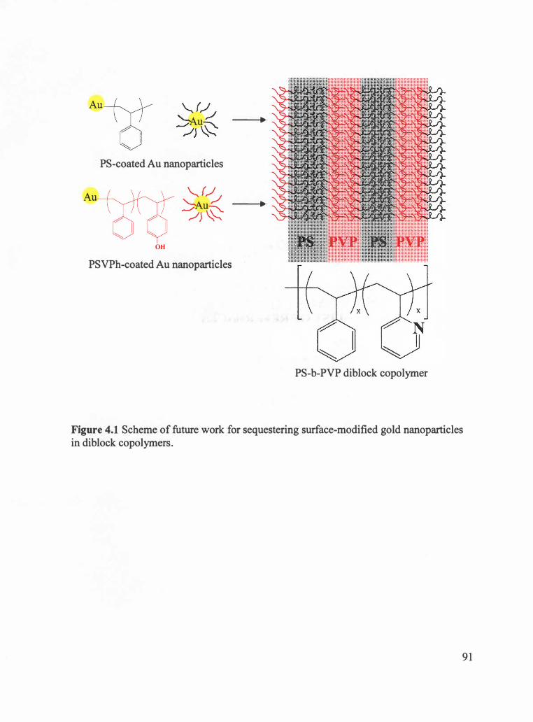
PS-coated Au nanoparticles
A
OH
PSVPh-coated Au nanoparticles
..
..
PS-b-PVP diblock copolymer
Figure 4.1 Scheme of future work for sequestering surface-modified gold nanoparticles in diblock copolymers.
9 1

LIST OF REFERENCES
92

LIST OF REFERENCES
(1) Fried, J. R. Polymer Science and Technology, Second ed. ; Prentice Hall Professional Technical Reference: Upper Saddle River, 2003.
(2) Krasteva, N.; Besnard, I.; Guse, B.; Bauer, R. E.; Mullen, K. ; Yasuda, A.; Vossmeyer, T. Nano Lett. 2002, 2, 551 .
(3) Balazs, A. C. Curr. Opin. Colloid Interf Sci. 2000, 4, 443.
(4) Thompson, R. B.; Ginzburg, V. V.; Matsen, M. W.; Balazs, A. C. Science 2001, 292, 2469.
(5) Thostenson, E. T.; Li, C.; Chou, T.-W. Compos. Sci. Technol. 2005, 65, 491 .
(6) Bockstaller, M. R. ; Mickiewicz, R. A.; Thomas, E. L. Adv. Mater. 2005, 1 7, 1331.
(7) Kawasumi, M. J. Polym. Sci. , Part A, Polym. Chem. 2004, 42.
(8) Okada, A.; Usuki, A. Materials Science & Engineering: C 1995, 3, 109.
(9) Bates, F. S.; Fredrickson, G. H. Annu. Rev. Phys. Chem. 1990, 41, 525.
(10) Thompson, R. B. ; Ginzburg, V. V.; Matsen, M. W.; Balazs, A. C. Macromolecules 2002, 35, 1060.
(11) Tsutsumi, K.; Funaki, Y.; Hirokawa, Y.; Hashimoto, T. Langmuir 1999, 15, 5200.
(12) Zehner, R. W.; Lopes, W. A.; Morkved, T. L.; Jaeger, H.; Sita, L. R. Langmuir 1998, 14, 241 .
(13) Boal, A. K.; Ilhan, F.; DeRouchey, J. E.; Thurn-Albrecht, T.; Russell, T. P. ; Rotello, V. M. Nature 2000, 404, 146.
(14) Bockstaller, M. R.; Lapetnikov, Y .. ; Margel, S.; Thomas, E. L. J. Am. Chem. Soc. 2003, 125, 5276.
(15) Shenhar, R.; Norsten, T. B.; Rotello, V. M. Adv. Mater. 2005, 1 7, 651.
(16) Galow, T. H. ; Drechsler, U.; Hanson, J. A.; Rotello, V. M. Chem. Commun. 2002, 1076.
(17) Iijima, S. Nature 1991, 354, 56.
(18) Meyyappan, M. Carbon Nanotubes Science and Applications; CRC Press: New
93

York, 2005.
(19) Moniruzzaman, M.; Winey, K. I. Macromolecules 2006, 39, 5194.
(20) Coleman, J. N. ; Khan, U. ; Gun'ko, Y. K. Adv. Mater. 2006, 18, 689.
(21) Gao, G; Cagin, T. ; Goddard, W. A. Nanotechnology 1998, 9, 184.
(22) Zhang, P. ; Lammert, P. E. ; Crespi, V. H. Physical Review Letters 1998, 81, 5346.
(23) Wong, E. W.; Sheehan, P. E. ; Lieber, C. M. Science 1997, 277, 1971.
(24) Wu, M.-F. ; Lourie, O. ; Dyer, M. J. ; Moloni, K. ; Kelly, T. F. ; Ruoff, R. S. Science 2000, 287, 637.
(25) Walters, D. A. ; Ericson, L. M. ; Casavant, M. J. ; Liu, J. ; Colbert, D. T. ; Smith, K. A. ; Smalley, R. E. Applied Physics Letters 1999, 74, 3803.
(26) Salvetat, J.-P. ; Briggs, G. A. D. ; Bonard, J.-M. ; Bacsa, R. R. ; Kulik, A. J. Physical Review Letters 1999, 82, 944.
(27) Uchida, T.; Kumar, S. Journal of Applied Polymer Science 2005, 98, 985.
(28) Dresselhaus, M. S.; Dresselhaus, G; Avouris, P. Carbon Nanotubes: Synthesis, Structure, Properties, and Applications; Springer: New York, 2000.
(29) Liu, L.; Barber, A. H. ; Nuriel, S. ; Wagner, H. D. Adv. Funct. Mater. 2005, 15, 915.
(30) Zhang, W. D. ; Shen, L. ; Phang, I. Y.; Liu, T. Macromolecules 2004, 37, 256.
(31) Wang, S.-F. ; Shen, L. ; Zhang, W.-D.; Tong, Y.-J. Biomacromolecules 2005, 6, 3067.
(32) Geng, H. ; Rosen, R. ; Zheng, B. ; Shimoda, H.; Fleming, L.; Liu, J. ; Zhou, 0. Adv. Mater. 2002, 14, 1387.
(33) Yang, J. ; Lin, Y. ; Wang, J. ; Lai, M. ; Li, J. ; Liu, J. ; Tong, X. ; Cheng, H. J. Appl. Polym. Sci. 2005, 98, 1087.
(34) Qian, D. ; Dickey, E. C. ; Andrews, R. ; Rantell, T. Appl. Phys. Lett. 2000, 76, 2868.
(35) Du, F. ; Fischer, J. E. ; Winey, K. I. J. Polym. Sci. , Part B: Polym. Phys. 2003, 41, 3333.
(36) Rasheed, A.; Chae, H. G; Kumar, S.; Dadmun, M. D. Polymer 2006, 47, 4734.
94
(37) Lee, J. Y.; Thompson, R. B. ; Jasnow, D. ; Balazs, A. C. Macromolecules 2002, 35, 4855.
(38) Bockstaller, M. R. ; Thomas, E. L. J. Phys. Chem. B 2003, 107, 10017.
(39) Chiu, J. J. ; Kim, B. J.; Kramer, E. J. ; Pine, D. J. J. Am. Chem. Soc. 2005, 127, 5036.
(40) Nano-lab. http://www.nano-lab.com/
( 41) Rasheed, A. The Role of Specific Interactions on the Dispersion and Properties of Carbon Nanotube-Polymer Nanocomposites, Ph. D. Dissertation, University of Tennessee, Knoxville, 2006.
(42) Baskaran, D. ; Mays, J. W.; Bratcher, M. S. Chem. Mater. 2005, 1 7, 3389.
(43) Stevens, M. P. Polymer Chemistry an Introduction, Third ed. ; Oxford University Press: New York, 1999.
(44) Pavia, D. L. ; Lampman, G. M.; Kriz, G S. Introduction to Spectroscopy; Harcourt College Publishers: Philadelphia, 2001.
(45) McNally, T. ; Potschke, P. ; Halley, P. ; Murphy, M. ; Martin, D. ; Bell, S. E. J. ; Brennan, G P.; Bein, D. ; Lemoine, P. ; Quinn, J. P. Polymer 2005, 46, 8222.
(46) Coleman, M. M.; Graf, J. F. ; Painter, P. C. Specific Interactions and the Miscibility of Polymer Blends; Technomic Publishing Company Inc.: Lancaster, 1991.
(47) Li, D. ; Brisson, J. Polymer 1998, 39, 793.
(48) Garamszegi, L.; Donzel, C.; Carrot, G; Nguyen, T. Q. ; Hilborn, J. Reactive & Functional Polymers 2003, 55, 179.
(49) Daniel, M.-C. ; Astruc, D. Chem. Rev. 2004, 104, 293 .
(50) Brust, M. ; Walker, M. ; Bethell, D. ; Schiffrin, D. J. ; Whyman, R. J. Chem. Soc. , Chem. Commun. 1994, 801.
(51) Bockstaller, M. ; Kolb, R.; Thomas, E. L. Adv. Mater. 2001, 13, 1783.
(52) Asari, T. ; Matsuo, S. ; Takano, A. ; Matsushita, Y. Polym. J. 2006, 38, 258.
(53) Wang, Z. L. Part. Part. Syst. Charact. 2001, 18, 142.
95

(54) Ohno, K. ; Ejaz, M.; Fukuda, T. ; Miyamoto, T. ; Shimizu, Y. Macromol. Chem. Phy� 1998, 199, 29 1 .
96
VITA
Chang-Uk Lee was born in Busan, South Korea on February 24th, 1976. He
graduated from Hyekwang High School in Busan in 1994. He attended Pusan National
University in Busan, South Korea, and received a Bachelor of Science degree in 2004
with a major in Polymer Science and Engineering. He then joined the graduate program
in the Materials Science and Engineering Department at the University of Tennessee,
Knoxville in August, 2004. He started graduate research as a research assistant in the
Chemistry Department under the direction of Professor Mark Dadmun in January, 2005.
He successfully defended his Master thesis in November, 2006, and received a Master of
Science degree with a major of Polymer Engineering in the Materials Science and
Engineering Department in December, 2006.
97

5873 8921 b 3 r 14114,'17 UR �