controlling the polarization state of light with a ...plab.nju.edu.cn/media/pdf/137.pdf ·...
TRANSCRIPT

Controlling the Polarization State of Light with a Dispersion-Free Metastructure
Shang-Chi Jiang,1 Xiang Xiong,1 Yuan-Sheng Hu,1 Yu-Hui Hu,1 Guo-Bin Ma,1
Ru-Wen Peng,1 Cheng Sun,2 and Mu Wang1*1National Laboratory of Solid State Microstructures and Department of Physics,
Nanjing University, Nanjing 210093, China2Department of Mechanical Engineering, Northwestern University, Evanston, Illinois 60208-3111, USA
(Received 31 October 2013; published 15 May 2014)
By combining the advantages of both a metallic metamaterial and a dielectric interlayer, we demonstratethe general mechanism to construct the dispersion-free metastructure, in which the intrinsic dispersion ofthe metallic structures is perfectly cancelled out by the thickness-dependent dispersion of the dielectricspacing layer. As examples to apply this concept, a broadband quarter-wave plate and a half-wave plate aredemonstrated. By selecting the structural parameters, the polarization state of light can be freely tunedacross a broad frequency range, and all of the polarization states on the Poincaré sphere can be realizeddispersion free.
DOI: 10.1103/PhysRevX.4.021026 Subject Areas: Metamaterials
Metamaterials are the artificial structures assembled withsubwavelength building blocks featuring some physicalproperties that do not exist in the natural world [1,2]. Overthe past decade, developments in this area have beencharacterized by the realization of numerous novel opticalproperties, such as negative refractive indices [3–5], super-lenses [6–8], etc. A two-dimensional metamaterial offersthe possibility of controlling light with miniaturized devi-ces, which are essential, especially for integrated photonics[9,10]. Furthermore, by engineering the phase discontinuityon an interface, one can fully steer light and accomplishunparalleled control of anomalous reflection and refraction[11–15] and realize different optical devices, such asoptical vortex plates [11,16] and wave plates [17]. It hasbeen well established that upon illumination of incidentlight, oscillating electric current can be excited on ametallic surface. The surrounding electromagnetic fieldis then modulated by the irradiation of oscillating surfaceelectric current. At resonant frequency, this effect is sosignificant that a thin layer of metallic structure caneffectively tune the state of light. However, the underlyingLorentz resonance in metal is highly dispersive in nature,which limits its application to a specific narrow wave band.Overcoming the dispersion of metamaterials is essentialfor wide optical applications. On the other hand, it isknown that the dielectric material interacts with light byaccumulating an optical path within a certain thickness.
This feature is effective over a broad bandwidth and hasalready been applied in antireflection coating and otheroptical devices [18–20]. By integrating a metallic meta-structure and a dielectric interlayer, it is possible to realizea dispersion-free broadband device on the subwavelengthscale, where the strong response of the metallic structureshelps to decrease the device size while the dielectricinterlayer helps to eliminate the dispersion simultaneouslyin both the amplitude and the phase difference of thereflected or transmitted light.Thus far, much effort has been devoted to broaden
the response frequency range of metallic metastructures[20–33]. For example, by superimposing different reso-nance modes within a unit cell, the bandwidth of thestructure can be broadened [25–30]. Additionally, ultrathin,broadband, and highly efficient metamaterial-based tera-hertz polarization converters have been realized recently,which rotate a linear polarization state into its orthogonalone [20]. Furthermore, a broadband quarter-wave plateconstructed with a periodic arrangement of metallic nano-bricks above a homogeneous metallic film separated by aninsulator layer has also been numerically demonstratedbased on gap-plasmon resonators [33]. It is always inter-esting to identify the essential physics mechanism of thesebroadband designs. In this paper, we illustrate a generalmechanism for manipulating the dispersion of a metastruc-ture by integrating a metallic metamaterial, which pos-sesses a strong yet dispersive interaction with light, witha dielectric interlayer, which has accumulative yet broad-band interaction with light. In this way, the intrinsicdispersion of the metallic structures is perfectly cancelledout by the thickness-dependent dispersion of the dielectricspacing layer. As examples to apply this concept, abroadband quarter-wave plate and a half-wave plate aredemonstrated. By proper selection of structural parameters,
*To whom all correspondence should be [email protected]
Published by the American Physical Society under the terms ofthe Creative Commons Attribution 3.0 License. Further distri-bution of this work must maintain attribution to the author(s) andthe published article’s title, journal citation, and DOI.
PHYSICAL REVIEW X 4, 021026 (2014)
2160-3308=14=4(2)=021026(6) 021026-1 Published by the American Physical Society

the polarization state of light can be freely tuned across abroad frequency range, and all of the polarization states onthe Poincaré sphere can be realized dispersion free.In particular, the approach described here can be appliedin designing other devices with dispersion-free features.Our structure consists of a layer of metallic metastructure
and a layer of perfect electric conductor (PEC) separatedby a dielectric layer with thickness d. (Here, we take thislayer as a vacuum in order to keep the formula simple.The details for the dielectric layer are provided in theSupplemental Material [34].) The response of each layerupon illumination of incident light ~Eince−ikz is schemati-cally shown in Fig. 1(a). For the metallic pattern withoutmagnetic response [35], the irradiation can be expressed as~Erade−ikðz−dÞ and ~Eradeikðz−dÞ for the waves propagating in−z and þz directions, respectively. The PEC layer acts as aperfect mirror. Therefore, the light reflected from the PECplane can be regarded as the mirror image of the incidentlight together with the radiation of the mirror image ofthe metallic structure, as illustrated by the red arrows inFig. 1(a). The mirror image of the incident light isexpressed as −~Einceikz. The mirror image of the metallicstructure is located at z ¼ −d and its irradiation isexpressed as two waves propagating in −z and þzdirections, respectively, −~Erade−ikðzþdÞ and −~EradeikðzþdÞ.It follows that the total reflection is the superposition of allcomponents of light propagating in the þz direction,
~Eref ¼ −~Einc þ ~Eradð−eikd þ e−ikdÞ: (1)
Here we have ignored the common factor eikz on both sidesof Eq. (1). It should be pointed out that both ~Erad and ~Eincare the vectors and their polarizations are not necessarilyidentical. Therefore, the polarization of the reflected lightcan be different from that of the incident light. Because ofthe resonance nature of the metallic structure, ~Erad isfrequency dependent. The term −eikd þ e−ikd reflects theconjugation relation between the radiation from the L-patterned layer and its mirror image. As the wave vector k isproportional to frequency, −eikd þ e−ikd is frequencydependent as well. However, at the same time, thedispersion of −eikd þ e−ikd depends on the separation d.By carefully selecting d, the dispersion of −eikd þ e−ikdcan compensate the dispersion of ~Erad. In this way, thedispersion-free feature is achieved [36].To implement this idea, an array of gold L patterns,
which is one of the simplest anisotropy resonators, isdesigned over a homogeneous, highly reflective silvermirror layer separated by a layer of SiO2, as shownin Fig. 1(b). Commercial software based on the finite-difference time-domain method is applied to simulate theresponse of the structure upon illumination of light (thedetails are provided in the Supplemental Material [34]).Before looking into the structure shown in Figs. 1(a)and 1(b), for comparison, it is interesting to investigate
the transmittance of an independent array of L patternswithout the mirror layer. When the incident light ispolarized along 45° or 135°, due to the symmetry of thestructure, the polarization of the transmitted and thereflected light does not change. The normalized electriccomponents of the transmitted light are shown in Fig. 1(c).The symmetric resonance mode and the antisymmetricresonance mode are excited by the 45° and 135° polarizedlight at the higher and lower frequencies, respectively,which has been reported [11]. Apparently, the bareL-patterned layer acts as a highly dispersive anisotropy
FIG. 1. (a) Schematics to show the interaction of light witheach interface of the system made of an array of L patterns(z ¼ d) in front of a perfect electric conductor (z ¼ 0). The mirrorimage of the array is located at z ¼ −d. (b) Structural parametersof the L pattern. The thickness of the silver mirror layer ish ¼ 100 nm, SiO2 layer thickness is d ¼ 510 nm. The length l,width w, and thickness b of each arm of the L pattern are 1220,120, and 120 nm, respectively. The lattice constant is 1550 nm.(c) Simulated transmission of a layer of gold L-pattern array only,without the silver mirror layer underneath. The black and redlines are the normalized amplitude of the electric componentof the transmitted light of 45°-and 135°-polarized incidence.(d) Simulated amplitude ratio of the reflected light, whichbecomes unity in the shaded frequency band. The inset showsthe total reflectance. (e) Simulated phase difference of thereflected light, which is either 90° or −90°.
JIANG et al. PHYS. REV. X 4, 021026 (2014)
021026-2

resonator. When a homogeneous silver mirror layer isintroduced beneath the structure at z ¼ 0, the transmissionof the structure is zero. The simulated total reflectance RxðyÞis shown in the inset of Fig. 1(d), where RxðyÞ is about 90%,indicating that the structure is an excellent reflector. Thesubscript in RxðyÞ represents the polarization of incidentlight. The amplitude ratio between the two components ofthe reflected light with both x- and y-polarized incidenceare calculated [Fig. 1(d)]. rij stands for the complexamplitude of the i component of the reflected light inducedby j-polarized incidence (i, j ¼ x, y). The phase differenceΔφiðjÞ is defined as the difference between the phase of they component and that of the x component of the reflectedlight, with the subscript of ΔφiðjÞ standing for the polari-zation of incident light. For the x-polarized incidence, in abroad frequency band ranging from 87 to 117 THz, theamplitude ratio remains unity and the phase difference Δφxis−90°, as illustrated in Figs. 1(d) and 1(e). This means thatthe reflected light has been changed to a right-handedcircularly polarized light. For the y-polarized incidence, aleft-handed circularly polarized reflected light is generatedin the same frequency range.The gold L patterns fabricated by electron beam lithog-
raphy (EBL) are shown in Fig. 2(a), beneath which a510-nm-thick SiO2 separation layer and a 100-nm-thickhomogeneous silver mirror layer have been fabricated bymagnetron sputtering on a silicon substrate. The measuredreflectance of the sample is larger than 0.85 in the responsefrequency [Fig. 2(b)]. From 86 to 116 THz, the amplituderatio remains unity for both the x- and y-polarizedincidence [Fig. 2(c)]. The phase difference is −90° for
the x-polarized incidence, and it becomes 90° for they-polarized incidence. Therefore, a dispersion-free quar-ter-wave plate is experimentally realized and the bandwidthreaches about 30% of the central frequency.The electromagnetic response of our structure can be
theoretically analyzed. For simplicity, here we ignore theloss of metal and take the refractive index of SiO2 as 1.0 inthe calculation. The irradiation field from the inducedsurface electric current is proportional to the total externalelectric field that excites the resonance of the surfaceelectric current, which is the superposition of the electriccomponents of the incident light and the light reflected bythe mirror plane. The electric field of light is expressed asa column vector, with subscripts x and y representing the xand y components of the electric field, respectively.It follows that
�Erad; x
Erad; y
�¼
�σ1 σ2
σ2 σ1
��Eext; x
Eext; y
�; (2)
where ~Eext is the total external field on the plane of Lpatterns. The symmetry of the σ matrix is due to the mirrorsymmetry of the structure in the diagonal direction. Bytaking the L-patterned unit as two connected RLC circuits[37], the elements in the σ matrix can be described by thesymmetric and antisymmetric modes as
σ1¼iγω
2ðω20−ω02−ω2− iγωÞþ
iγω2ðω2
0þω02−ω2− iγωÞ;
σ2¼− iγω2ðω2
0−ω02−ω2− iγωÞþiγω
2ðω20þω02−ω2− iγωÞ ;
(3)
where ω0 denotes the response frequency of each individ-ual arm, ω0 denotes the interaction between them, and γrepresents the effective resistance.For a bare layer of L patterns only, the excitation field for
the resonance of the L pattern ~Eext is merely the incidentlight ~Einc. Meanwhile, the transmission is the superpositionof the incident light and the radiation light based on Eq. (2).For the integrated structure, however, the radiation of thearray of L patterns is excited by both the incident light andthe reflected light from the PEC plane, as illustrated inFig. 1(a). It follows that
~Eext ¼ ~Eince−ikd − ~Einceikd − ~Erade2ikd: (4)
From Eqs. (1)–(4), we can get the reflected field ~Eref .
Suppose the incident light
�Einc x
Einc y
�is x-polarized and is
denoted as�1
0
�. The parameters in Eq. (3) (ω0, ω0, and γ)
can be retrieved from the simulation of a single-layered L
FIG. 2. (a) Field-emission scanning electron micrograph of thearray of gold L patterns fabricated by electron beam lithography.The bar represents 5 μm. (b) Experimentally measured reflec-tance for the x- and y-polarized incident light. (c),(d) Experi-mentally measured amplitude ratio and phase difference ofthe sample under the illumination of x- and y-polarized light,respectively.
CONTROLLING THE POLARIZATION STATE OF LIGHT … PHYS. REV. X 4, 021026 (2014)
021026-3
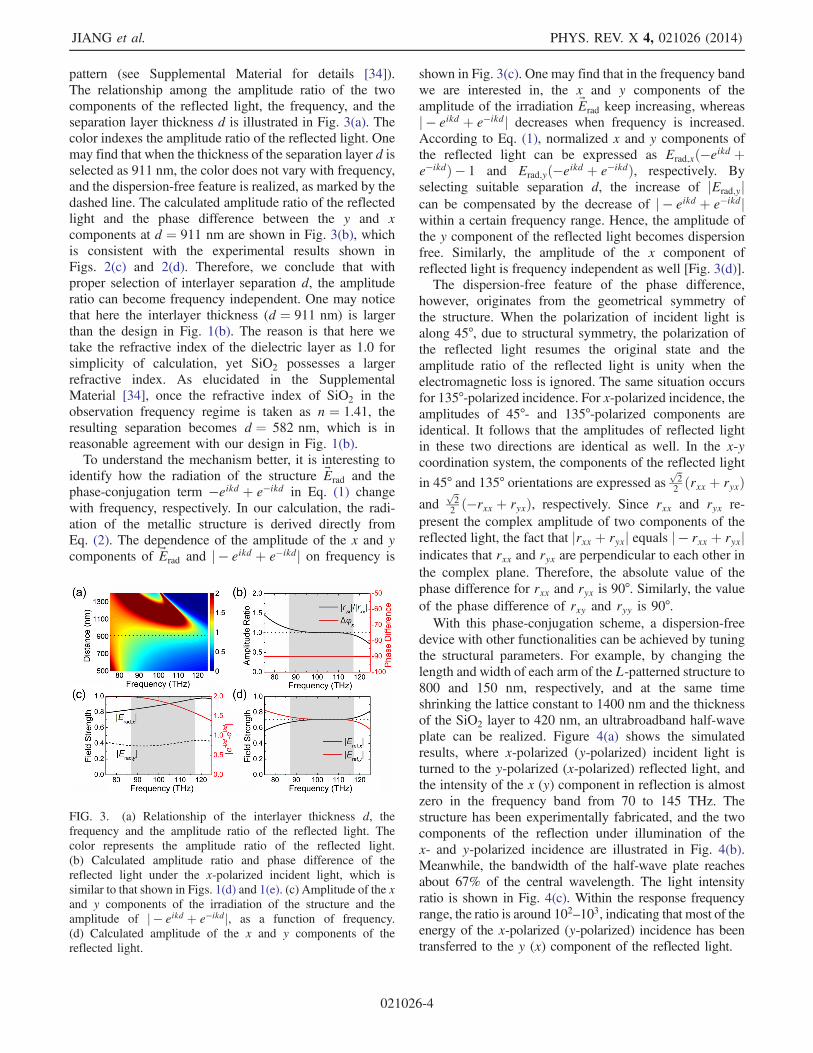
pattern (see Supplemental Material for details [34]).The relationship among the amplitude ratio of the twocomponents of the reflected light, the frequency, and theseparation layer thickness d is illustrated in Fig. 3(a). Thecolor indexes the amplitude ratio of the reflected light. Onemay find that when the thickness of the separation layer d isselected as 911 nm, the color does not vary with frequency,and the dispersion-free feature is realized, as marked by thedashed line. The calculated amplitude ratio of the reflectedlight and the phase difference between the y and xcomponents at d ¼ 911 nm are shown in Fig. 3(b), whichis consistent with the experimental results shown inFigs. 2(c) and 2(d). Therefore, we conclude that withproper selection of interlayer separation d, the amplituderatio can become frequency independent. One may noticethat here the interlayer thickness (d ¼ 911 nm) is largerthan the design in Fig. 1(b). The reason is that here wetake the refractive index of the dielectric layer as 1.0 forsimplicity of calculation, yet SiO2 possesses a largerrefractive index. As elucidated in the SupplementalMaterial [34], once the refractive index of SiO2 in theobservation frequency regime is taken as n ¼ 1.41, theresulting separation becomes d ¼ 582 nm, which is inreasonable agreement with our design in Fig. 1(b).To understand the mechanism better, it is interesting to
identify how the radiation of the structure ~Erad and thephase-conjugation term −eikd þ e−ikd in Eq. (1) changewith frequency, respectively. In our calculation, the radi-ation of the metallic structure is derived directly fromEq. (2). The dependence of the amplitude of the x and ycomponents of ~Erad and j − eikd þ e−ikdj on frequency is
shown in Fig. 3(c). One may find that in the frequency bandwe are interested in, the x and y components of theamplitude of the irradiation ~Erad keep increasing, whereasj − eikd þ e−ikdj decreases when frequency is increased.According to Eq. (1), normalized x and y components ofthe reflected light can be expressed as Erad;xð−eikd þe−ikdÞ − 1 and Erad;yð−eikd þ e−ikdÞ, respectively. Byselecting suitable separation d, the increase of jErad;yjcan be compensated by the decrease of j − eikd þ e−ikdjwithin a certain frequency range. Hence, the amplitude ofthe y component of the reflected light becomes dispersionfree. Similarly, the amplitude of the x component ofreflected light is frequency independent as well [Fig. 3(d)].The dispersion-free feature of the phase difference,
however, originates from the geometrical symmetry ofthe structure. When the polarization of incident light isalong 45°, due to structural symmetry, the polarization ofthe reflected light resumes the original state and theamplitude ratio of the reflected light is unity when theelectromagnetic loss is ignored. The same situation occursfor 135°-polarized incidence. For x-polarized incidence, theamplitudes of 45°- and 135°-polarized components areidentical. It follows that the amplitudes of reflected lightin these two directions are identical as well. In the x-ycoordination system, the components of the reflected light
in 45° and 135° orientations are expressed asffiffi2
p2ðrxx þ ryxÞ
andffiffi2
p2ð−rxx þ ryxÞ, respectively. Since rxx and ryx re-
present the complex amplitude of two components of thereflected light, the fact that jrxx þ ryxj equals j − rxx þ ryxjindicates that rxx and ryx are perpendicular to each other inthe complex plane. Therefore, the absolute value of thephase difference for rxx and ryx is 90°. Similarly, the valueof the phase difference of rxy and ryy is 90°.With this phase-conjugation scheme, a dispersion-free
device with other functionalities can be achieved by tuningthe structural parameters. For example, by changing thelength and width of each arm of the L-patterned structure to800 and 150 nm, respectively, and at the same timeshrinking the lattice constant to 1400 nm and the thicknessof the SiO2 layer to 420 nm, an ultrabroadband half-waveplate can be realized. Figure 4(a) shows the simulatedresults, where x-polarized (y-polarized) incident light isturned to the y-polarized (x-polarized) reflected light, andthe intensity of the x (y) component in reflection is almostzero in the frequency band from 70 to 145 THz. Thestructure has been experimentally fabricated, and the twocomponents of the reflection under illumination of thex- and y-polarized incidence are illustrated in Fig. 4(b).Meanwhile, the bandwidth of the half-wave plate reachesabout 67% of the central wavelength. The light intensityratio is shown in Fig. 4(c). Within the response frequencyrange, the ratio is around 102–103, indicating that most of theenergy of the x-polarized (y-polarized) incidence has beentransferred to the y (x) component of the reflected light.
FIG. 3. (a) Relationship of the interlayer thickness d, thefrequency and the amplitude ratio of the reflected light. Thecolor represents the amplitude ratio of the reflected light.(b) Calculated amplitude ratio and phase difference of thereflected light under the x-polarized incident light, which issimilar to that shown in Figs. 1(d) and 1(e). (c) Amplitude of the xand y components of the irradiation of the structure and theamplitude of j − eikd þ e−ikdj, as a function of frequency.(d) Calculated amplitude of the x and y components of thereflected light.
JIANG et al. PHYS. REV. X 4, 021026 (2014)
021026-4

The dispersion-free quarter- and half-wave plates allowturning 50% and 100% of the reflected power from onepolarization to the perpendicular polarization of thereflected light over a broad frequency band. Moreover,the amplitude ratio between the two perpendicular compo-nents of the reflected light can be continuously tuned, and adispersion-free wave plate with nonunity amplitude ratiocan be realized by selecting the structural parameters of theL-patterned array. For example, when the length and widthof each arm of the L pattern are selected as 1290 and155 nm, respectively, and we keep the other parametersidentical to those in Fig. 1(b), the amplitude ratio becomes0.84 and 1.19 for x- and y-polarized incidence, respec-tively, in the range of 84–113 THz, as illustrated inFig. 4(d). Meanwhile, the phase difference remains −90°and 90° [see the inset of Fig. 4(d)]. In this way, a dispersion-free wave plate for elliptical polarized light is achieved.Controlling the state of light has been an important topic
in nanophotonics. Metamaterials and plasmonics providethe opportunity to miniaturize the devices and realizedifferent wave plate functionalities with new principles.By integrating metallic metastructures and dielectric inter-layer, the intrinsic dispersion generated by the resonanceof metallic structures is compensated by the interlayer-thickness-sensitive dispersion of the dielectric interlayer, sothe dispersion-free optical functionalities can be realized ina very restricted space. We also point out that the principlepresented here is universal in physics, and is not limited to
tuning the polarization state of light only. Instead, weexpect that it can be applied in designing other devices withbroadband features and can help to make the ultimatedream of mastering light on the nanoscale come true.
The authors acknowledge support from the MOST ofChina (Grants No. 2010CB630705 and No. 2012CB921502),the NSF of China (Grants No. 50972057, No. 11034005,No. 11204127, and No. 61077023), the MOE of China(SRFDP No. 20120091120033), and partial support byJiangsu Province (Grant No. BK2012301).
[1] C. M. Soukoulis and M. Wegener, Past Achievementsand Future Challenges in the Development of Three-Dimensional Photonic Metamaterials, Nat. Photonics5, 523 (2011).
[2] Y. Liu and X. Zhang, Metamaterials: A New Frontier ofScience and Technology, Chem. Soc. Rev. 40, 2494 (2011).
[3] D. R. Smith, W. J. Padilla, D. C. Vier, S. C. Nemat-Nasser,and S. Schultz, Composite Medium with SimultaneouslyNegative Permeability and Permittivity, Phys. Rev. Lett. 84,4184 (2000).
[4] R. A. Shelby, D. R. Smith, and S. Schultz, ExperimentalVerification of a Negative Index of Refraction, Science 292,77 (2001).
[5] J. Valentine, S. Zhang, T. Zentgraf, E. Ulin-Avila, D. A.Genov, G. Bartal, and X. Zhang, Three-DimensionalOptical Metamaterial with a Negative Refractive Index,Nature (London) 455, 376 (2008).
[6] N. Fang, H. Lee, C. Sun, and X. Zhang, Sub-Diffraction-Limited Optical Imaging with a Silver Superlens, Science308, 534 (2005).
[7] Z. Liu, H. Lee, Y. Xiong, C. Sun, and X. Zhang, Far-FieldOptical Hyperlens Magnifying Sub-Diffraction-LimitedObjects, Science 315, 1686 (2007).
[8] I. I. Smolyaninov, Y.-J. Hung, and C. C. Davis, MagnifyingSuperlens in the Visible Frequency Range, Science 315,1699 (2007).
[9] R. G. Hunsperger, Integrated Optics:Theory andTechnology (Springer, New York, 2009), 6th ed.
[10] A. V. Kildishev, A. Boltasseva, and V. M. Shalaev, PlanarPhotonics with Metasurfaces Science 339, 1232009 (2013).
[11] N. Yu, P. Genevet, M. A. Kats, F. Aieta, J.-P. Tetienne,F. Capasso, and Z. Gaburro, Light Propagation with PhaseDiscontinuities: Generalized Laws of Reflection andRefraction, Science 334, 333 (2011).
[12] X. Ni, N. K. Emani, A. V. Kildishev, A. Boltasseva, andV. M. Shalaev, Broadband Light Bending with PlasmonicNanoantennas, Science 335, 427 (2012).
[13] A. Pors, O. Albrektsen, I. P. Radko, and S. I. Bozhevolnyi,Gap-Plasmon-Based Metasurfaces for Total Control ofReflected Light, Sci. Rep. 3, 2155 (2013).
[14] S. Sun, K.-Y. Yang, C.-M. Wang, T.-K. Juan, W. T. Chen,C. Y. Liao, Q. He, S. Xiao, W.-T. Kung, G.-Y. Guo, L. Zhou,and D. P. Tsai, High-Efficiency Broadband AnomalousReflection by Gradient Meta-Surfaces, Nano Lett. 12,6223 (2012).
FIG. 4. (a) Simulated reflectance for a broadband half-waveplate. (b) Experimentally measured reflectance of the fabricatedsample, which is in good agreement with simulations.(c) Measured intensity ratio between the x and y componentsof reflectance. (d) The wave plate to generate the ellipticalpolarized light has been fabricated. The measurements showthat the amplitude ratio between the two components of thereflected light deviates from 1 in the shaded region, whereas thephase difference (inset) between the two orthogonal componentsremains 90°.
CONTROLLING THE POLARIZATION STATE OF LIGHT … PHYS. REV. X 4, 021026 (2014)
021026-5

[15] A. Pors, M. G. Nielsen, R. L. Eriksen, and S. I. Bozhevolnyi,Broadband Focusing Flat Mirrors Based on PlasmonicGradient Metasurfaces, Nano Lett. 13, 829 (2013).
[16] P. Genevet, N. Yu, F. Aieta, J. Lin, M. A. Kats, R.Blanchard, M. O. Scully, Z. Gaburro, and F. Capasso,Ultrathin Plasmonic Optical Vortex Plate Based on PhaseDiscontinuities, Appl. Phys. Lett. 100, 013101 (2012).
[17] N. Yu, F. Aieta, P. Genevet, M. A. Kats, Z. Gaburro, andF. Capasso, A Broadband, Background-Free Quarter-WavePlate Based on Plasmonic Metasurfaces, Nano Lett. 12,6328 (2012).
[18] M. Born and E. Wolf, Principles of Optics (CambridgeUniversity Press, Cambridge, England,, 1999), 7th ed.
[19] H.-T. Chen, J. Zhou, J. F. O’Hara, F. Chen, A. K. Azad, andA. J. Taylor, Antireflection Coating Using Metamaterialsand Identification of Its Mechanism, Phys. Rev. Lett. 105,073901 (2010).
[20] N. K. Grady, J. E. Heyes, D. R. Chowdhury, Y. Zeng,M. T. Reiten, A. K. Azad, A. J. Taylor, D. A. R. Dalvit, andH.-T. Chen, Terahertz Metamaterials for Linear Polariza-tion Conversion and Anomalous Refraction, Science 340,1304 (2013).
[21] J. K. Gansel, M. Thiel, M. S. Rill, M. Decker, K. Bade,V. Saile, G. von Freymann, S. Linden, and M. Wegener,Gold Helix Photonic Metamaterial as Broadband CircularPolarizer, Science 325, 1513 (2009).
[22] J. K. Gansel, M. Latzel, A. Frolich, J. Kaschke, M. Thiel,and M. Wegener, Tapered Gold-Helix Metamaterials asImproved Circular Polarizers, Appl. Phys. Lett. 100,101109 (2012).
[23] C. Wu, H. Li, X. Yu, F. Li, H. Chen, and C. T. Chan,Metallic Helix Array as a Broadband Wave Plate, Phys.Rev. Lett. 107, 177401 (2011).
[24] Z. Y. Yang, M. Zhao, P. X. Lu, and Y. F. Lu, Ultrabroad-band Optical Circular Polarizers Consisting of Double-Helical Nanowire Structures, Opt. Lett. 35, 2588 (2010).
[25] Y. Zhao, M. A. Belkin, and A. Alù, Twisted OpticalMetamaterials for Planarized Ultrathin BroadbandCircular Polarizers, Nat. Commun. 3, 870 (2012).
[26] F. Ding, Y. Cui, X. Ge, Y. Jin, and S. He, Ultra-BroadbandMicrowave Metamaterial Absorber, Appl. Phys. Lett. 100,103506 (2012).
[27] D. R. Chowdhury, R. Singh, M. Reiten, H.-T. Chen, A. J.Taylor, J. F. O’Hara, and A. K. Azad, A Broadband Planar
Terahertz Metamaterial with Nested Structure, Opt. Express19, 15817 (2011).
[28] N. R. Han, Z. C. Chen, C. S. Lim, B. Ng, and M. H. Hong,Broadband Multilayer Terahertz Metamaterials Fabricationand Characterization on Flexible Substrates, Opt. Express19, 6990 (2011).
[29] Z. Wei, Y. Cao, Y. Fan, X. Yu, and H. Li, BroadbandPolarization Transformation via Enhanced AsymmetricTransmission through Arrays of Twisted ComplementarySplit-Ring Resonators, Appl. Phys. Lett. 99, 221907(2011).
[30] X. Xiong, W.-H. Sun, Y.-J. Bao, R.-W. Peng, M. Wang,C. Sun, X. Lu, J. Shao, Z.-F. Li, and N.-B. Ming, Switchingthe Electric and Magnetic Responses in a Metamaterial,Phys. Rev. B 80, 201105(R) (2009).
[31] Y. Zhao and A. Alù, Tailoring the Dispersion of PlasmonicNanorods To Realize Broadband Optical Meta-WavePlates, Nano Lett. 13, 1086 (2013).
[32] P. E. Sieber and D. H. Werner, Reconfigurable BroadbandInfrared Circularly Polarizing Reflectors Based on PhaseChanging Birefringent Metasurfaces, Opt. Express 21, 1087(2013).
[33] A. Pors and S. I. Bozhevolnyi, Efficient and BroadbandQuarter-Wave Plates by Gap-Plasmon Resonators, Opt.Express 21, 2942 (2013).
[34] See Supplemental Material at http://link.aps.org/supplemental/10.1103/PhysRevX.4.021026 for the detailsof the physical modeling describing our system and thesimulation results.
[35] M. Albooyeh, D. Morits, and S. A. Tretyakov, EffectiveElectric and Magnetic Properties of Metasurfaces inTransition from Crystalline to Amorphous State, Phys.Rev. B 85, 205110 (2012).
[36] For the scenario that the interlayer is another dielectricmaterial instead of air, the expression for the reflectedlight becomes more complicated than Eq. (1) due toreflection and refraction at the dielectric-air boundary, yetthe fundamental principle to achieve dispersion-free featureis the same.
[37] S.-C. Jiang, X. Xiong, P. Sarriugarte, S.-W. Jiang, X.-B. Yin,Y. Wang, R.-W. Peng, D. Wu, R. Hillenbrand, X. Zhang,and M. Wang, Tuning the Polarization State of Light viaTime Retardation with a Microstructured Surface, Phys.Rev. B 88, 161104(R) (2013).
JIANG et al. PHYS. REV. X 4, 021026 (2014)
021026-6