controls – contactors and contactor assemblies 3 — contactors and contactor assemblies...
TRANSCRIPT

Siemens LV 1 · 2006
33/2 Introduction
3RT, 3TB, 3TF Contactors for Switching Motors
3/4 General data3/8 3RT10 contactors, 3-pole, 3 ... 250 kW3/30 3RT12 vacuum contactors, 3-pole,
110 ... 250 kW3/31 3TF6 vacuum contactors, 3-pole,
335 ... 450 kW3/34 3TB5 contactors with DC solenoid
system, 3-pole, 55 ... 200 kW3/35 3TF2 contactors, 3-pole, 2.2 ... 4 kW
3RA13, 3RA14 Contactor Assemblies3RA13 Reversing Contactor Assemblies
3/38 3RA13 complete units, 3 ... 45 kW3/43 Components for customer assembly
3RA14 Contactor Assemblies for Wye-Delta Starting
3/46 3RA14 complete units, 3 ... 75 kW3/53 Components for customer assembly
3TD, 3TE Contactor Assemblies3/54 3TD6 reversing contactor assemblies,
335 kW3/55 3TE6 contactor assemblies for
wye-delta starting, 630 kW
3RT, 3RH, 3TB, 3TC, 3TH, 3TK Contactors for Special Applications3RT14 Contactors for Switching Resistive Loads (AC-1)
3/56 3-pole, 140 ... 690 A3RT13 Contactors for Switching Resistive Loads (AC-1)
3/58 4-pole, 4 NO, 18 ... 140 A3TK1 Contactors for Switching Resistive Loads (AC-1)
3/61 4-pole, 4 NO, 200 ... 1000 A3TK20 Contactors
3/62 4-pole, 4 kW3RT15 Contactors
3/64 4-pole, 2 NO + 2 NC, 4 ... 18.5 kW3RT16 Capacitor Contactors
3/66 12.5 ... 50 kvarContactors with Extended Tolerance 0.7 ... 1.25 × Us, forRailway Applications
3/67 3RH11 contactor relays3/68 3TH4 contactor relays3/69 3RT10 motor contactors, 5.5 ... 45 kW3/73 3TB5 motor contactors, 55 ... 200 kW3/74 3TC contactors for switching
DC voltage, 2-pole3TC Contactors for Switching DC Voltage
3/75 1- and 2-pole, 32 ... 400 A
3RH, 3TH Contactor Relays3/78 3RH1 contactor relays, 4- and 8-pole3/82 3RH14 latched contactor relays,
4-pole3/83 3TH4 contactor relays, 8- and 10-pole3/85 3TH2 contactor relays, 4- and 8-pole3/88 3RH11 coupling relays for switching
auxiliary circuits, 4-pole
3RT Coupling Relays3/90 3RT10 coupling relays (interface),
for switching motors, 3-pole, 3 ... 11 kW
3TX7, 3RS18 Coupling Relays
3TX7 Coupling Relays, NarrowDesign
3/95 Relay couplers3/97 Relay couplers with plug-in design3/99 Semiconductor couplers
3RS18 Coupling Relays with Industrial Housing
3/101 Relay couplers
LZX Plug-in Relays3/102 Relay couplers
3TG10 Power Relays/Miniature Contactors
3/106 4-pole, 4 kW
Accessories and Spare Parts
for 3RT, 3RH Contactors and Contactor Relays
3/107 Accessories for 3RT, 3RH contactors and contactor relays
3/126 Spare parts for 3RT, 3RH contactors and contactor relays
for 3T Contactors and Contactor Relays
3/134 Accessories for 3TB, 3TC, 3TF, 3TG, 3TK contactors
3/139 Accessories for 3TH contactor relays3/142 Spare parts for 3TB, 3TC,
3TF, 3TK contactors
Controls –Contactors andContactor Assemblies

Controls — Contactors and Contactor Assemblies
Introduction
3/2 Siemens LV 1 · 2006
3
■ Overview
SizeType
S003RT10 1
S03RT10 2
S23RT10 3
3RT10 contactors � 3RT12 and 3TF68/69 vacuum contactorsType 3RT10 15 3RT10 16 3RT10 17 3RT10 23 3RT10 24 3RT10 25 3RT10 26 3RT10 34 3RT10 35 3RT10 36AC, DC operation (p. 3/12, 3/20) (p. 3/14, 3/22) (p. 3/16, 3/24)
Type -- -- --
AC-3
Ie/AC-3/400 V A 7 9 12 9 12 17 25 32 40 50
400 V kW 3 4 5.5 4 5.5 7.5 11 15 18.5 22
230 V 500 V 690 V
1 000 V3RT10/123RT10/12
kWkWkWkW
2.23.54
--
34.55.5
--
35.55.5
--
34.55.5
--
37.57.5
--
41011--
5.51111--
7.518.518.5--
112222--
153022--
AC-4 (for Ia = 6 x Ie)
400 V400 V 3RT10/12
kWkW
31.15
42
42
42
5.52.6
7.53.5
7.54.4
158.2
18.59.5
2212.6
(200 000 operating cycles)
AC-1 (40 °C, � 690 V)
Ie 3RT10/12 A 18 22 22 40 40 40 40 50 60 60
3RT14 AC-1 contactorsType -- -- --
Ie/AC-1/40 °C/� 690 V A -- -- --
Accessories for contactorsAuxiliary switch blocks front
lateral3RH19 11--
(p. 3/110) 3RH19 213RH19 21
(p. 3/110)(p. 3/114)
Terminal covers -- -- 3RT19 36-4EA2 (p. 3/124)
Box terminal blocks -- -- --
Surge suppressors 3RT19 16 (p. 3/119) 3RT19 26 (p. 3/119) 3RT19 26/36 (p. 3/119)
3RU1 and 3RB2 overload relays (protection equipment: overload relays)3RU11, thermal, CLASS 10 3RU11 16 0.1 ... 12 A (Chap. 5) 3RU11 26 1.8 ... 25 A (Chapter 5) 3RU11 36 5.5 ... 50 A (Chapter 5)
3RB20/21, solid-state, CLASS 5, 10, 20 and 30
3RB20 163RB21 16
0.1 ... 12 A (Chap. 5) 3RB20 263RB21 26
3 ... 25 A (Chapter 5) 3RB20 363RB21 36
6 ... 50 A (Chapter 5)
3RB22/23, solid-state, CLASS 5, 10, 20 and 30
3RB2. 83 + 3RB29 06 3RB2. 83 + 3RB29 060.3 ... 25 A (Chapter 5) 10 ... 100 A (Chapter 5)
3RV10 motor starter protectors (protection equipment: circuit-breakers)Type 3RV10 11 0.18 ... 12 A (Chap. 5) 3RV10 21 9 ... 25 A (Chapter 5) 3RV10 31 22 ... 50 A (Chapter 5)
Link modules 3RA19 11 (Chap. 5) 3RA19 21 (Chapter 5) 3RA19 31 (Chapter 5)
3RA13 reversing contactor assembliesComplete units Type 3RA13 15
(p. 3/39)3RA13 16 3RA13 17 3RA13 24
(p. 3/40)3RA13 25 3RA13 26 3RA13 34
(p. 3/41)3RA13 35 3RA13 36
400 V kW 3 4 5.5 5.5 7.5 11 15 18.5 22
Installation kits/wiring connectors 3RA19 13-2A (p. 3/44) 3RA19 23-2A (p. 3/44) 3RA19 33-2A (p. 3/44)
Mechanical interlocks 3RA19 12-2H (p. 3/45) 3RA19 24-1A/-2B (p. 3/43)
3RA14 contactor assemblies for wye-delta startingComplete units Type 3RA14 15
(p. 3/48)3RA14 16 3RA14 23
(p. 3/49)3RA14 25 3RA14 34
(p. 3/50)3RA14 35(p. 3/51)
3RA14 36
400 V kW 5.5 7.5 11 15/18.5 22/30 37 45
Installation kits/wiring connectors 3RA19 13-2B (p. 3/53) 3RA19 23-2B (p. 3/53) 3RA19 33-2B/-2C (p. 3/53)

Controls — Contactors and Contactor Assemblies
Introduction
3/3Siemens LV 1 · 2006
3
S33RT1. 4
S63RT1. 5
S103RT1. 6
S123RT1. 7
143TF6
3RT10 44 3RT10 45 3RT10 46 3RT10 54 3RT10 55 3RT10 56 3RT10 64 3RT10 65 3RT10 66 3RT10 75 3RT10 76 --(p. 3/18, 3/24) (p. 3/26) (p. 3/26) (p. 3/26)
-- -- 3RT12 64(p. 3/30)
3RT12 65 3RT12 66 3RT12 75(p. 3/30)
3RT12 76 3TF68(p. 3/32)
3TF69
65 80 95 115 150 185 225 265 300 400 500 630 820
30 37 45 55 75 90 110 132 160 200 250 335 450
18.5374530
22455537
22555537
3775
11075
4590
13290
5511016090
5516020090/315
75160250132/355
90200250132/400
132250400250/560
160355400/500250/710
200434600600
260600800800
3015.1
3717.9
4522
5529
7538
9045
11054/78
13266/93
16071/112
20084/140
25098/161
355168
400191
100 120 120 160 185 215 275/330 330 330 430/610 610 700 910
3RT14 46 (p. 3/56) 3RT14 56 (p. 3/57) 3RT14 66 (p. 3/57) 3RT14 76 (p. 3/57) --
140 275 400 690 --
--3TY7 561 (p. 3/135)
3RT19 46-4EA1/2 (p. 3/124) 3RT19 56-4EA1/2/3 (p. 3/124) 3RT19 66-4EA1/2/3 (p. 3/124) 3TX7 686/696 (p. 3/135)
-- 3RT19 55/56-4G (p. 3/124) 3RT19 66-4G (p. 3/124) --
3RT19 56-1C (RC element) (p. 3/120) 3TX7 572 (p. 3/134)
3RU11 46 18 ... 100 A (Chapter 5) -- -- -- --
3RB20 463RB21 46
12.5 ... 100 A (Chap. 5) 3RB20 563RB21 56
50 ... 200 A (Chapter 5) 3RB20 663RB21 66
55 ... 630 A(Chapter 5)
3RB20 663RB21 66
160 ... 630 A (Chapter 5)
3RB20 663RB21 66
160 ... 630 A (Chapter 5)
3RB2. 83 + 3RB29 56 3RB2. 83 + 3RB29 6620 ... 200 A (Chapter 5) 63 ... 630 A (Chapter 5)
3RV10 41 45 ... 100 A (Chapter 5) -- -- -- --
3RA19 41 (Chapter 5) -- -- -- --
3RA13 44(p. 3/42)
3RA13 45 3RA13 46 -- -- -- 3TD68 04(p. 3/54)
30 37 45 55 75 90 110 132 160 200 250 335
3RA19 43-2A (p. 3/44) 3RA19 53-2A (p. 3/44) 3RA19 63-2A (p. 3/44) 3RA19 73-2A (p. 3/44) 3TX7 680-1A
3RA19 54-2A (p. 3/43) 3TX7 686-1A
3RA14 44(p. 3/52)
3RA14 45 -- -- -- 3TE68 04(p. 3/55)
55 75 -- -- -- 630
3RA19 43-2B/-2C (p. 3/53) 3RA19 53-2B (p. 3/53) 3RA19 63-2B (p. 3/53) 3RA19 73-2B (p. 3/53) 3TX7 680-1B

3RT, 3TB, 3TF Contactors for Switching Motors
General data
3/4 Siemens LV 1 · 2006
3
■ Overview
3RT1 contactors and coupling relaysSize S00 with mountable accessories
For contactor assemblies see pages 3/38 to 3/45Assembly kit for reversing contactor assemblies(mech. interlocking, wiring modules) see page 3/44For mountable overload relays see Protection Equipment: Overload Relays For fuseless load feeders, see Load Feeders, Motor Starters and Soft Starters -> 3RA Fuseless Load Feeders
The SIRIUS generation of controls is a complete, modular system family, logically designed right down to the last detail, from the basic units to the accessories.
Contactor (page 3/12)Coupling relay (page 3/90)Solid-state time-delay block, ON-delay (page 3/118)Solid-state time-delay block, OFF-delay (page 3/118)Auxiliary switch block, solid-state time-delay (page 3/117)(ON or OFF-delay or wye-delta function)Single-pole auxiliary switch block, cable entry from above (page 3/110)2-pole auxiliary switch block, cable entry from above (page 3/110)Single-pole auxiliary switch block, cable entry from below (page 3/110)2-pole auxiliary switch block, cable entry from below (page 3/110)4-pole auxiliary switch block (page 3/110) (terminal designationsaccording to EN 50012 or EN 50005)2-pole auxiliary switch block, standard design or solid-state compatible design (pages 3/110, 3/117) (terminal designations according to EN 50005)Solder pin adapter for contactors with 4-pole auxiliary switch block (page 3/123)Solder pin adapter for contactors and coupling relays (page 3/122)
Additional load module for increasing the permissible residual current (page 3/121)Surge suppressor with LED (page 3/120)Surge suppressor without LED (page 3/120)3-phase feeder terminal (page 3/53)Link for paralleling (star jumper), 3-pole,without terminal (page 3/53)Link for paralleling, 3-pole, with terminal (page 3/123)Link for paralleling, 4-pole, with terminal (page 3/123)
For contactorsFor contactors and coupling relays (interface)
��
���
���
��
�
�
�
�
�
��
��
��
���
�
�
�
�
��
��
12345
678910
11
12
13
14
15161718
1920

3RT, 3TB, 3TF Contactors for Switching Motors
General data
3/5Siemens LV 1 · 2006
3
3RT1 contactorsSizes S0 to S3 with mountable accessories
��
���
����
��
�
��
�
��
��
�
��
�
�
�
��
��
�
�
�
�
�
��
�
�
�
�
�
Contactor, size S0, see page 3/14Contactor, size S2, see page 3/16Contactor, size S3, see page 3/18
123
For sizes S0 to S3:
Solid-state time-delay block, ON-delay (page 3/118)Solid-state time-delay block, OFF-delay (page 3/118)Auxiliary switch block, solid-state time-delay (page 3/117)(ON or OFF-delay or wye-delta function)2-pole auxiliary switch block, cable entry from above (page 3/112)2-pole auxiliary switch block, cable entry from below (page 3/112)4-pole auxiliary switch block (page 3/112)(terminal designations according to EN 50012 or EN 50005)Link for paralleling (star jumper), 3-pole, without terminal (page 3/53)Link for paralleling, 3-pole, with terminal (page 3/123)2-pole auxiliary switch block, laterally mountable (left or right)(page 3/114) (terminal designations according to EN 50012 or EN 50005)Single-pole auxiliary switch block (up to 4 can be snapped on) (page 3/112)Mechanical interlock, laterally mountable (page 3/43)Mechanical interlock, mountable on the front (page 3/43)Wiring connectors on the top and bottom (reversing duty) (page 3/45)Surge suppressors (page 3/119) (varistor, RC element, diode assembly), can be mounted on the top or bottom (different for S0 and S2/S3)
Interface for mounting directly onto contactor coil (page 3/122)LED module for indicating contactor operation (page 3/122)
Only for size S0:
Pneumatic delay block (page 3/118)
Only for sizes S0 and S2:
Mechanical latching
Only for sizes S2 and S3:
Repeat coil terminal for making contactor assemblies (page 3/43)Terminal cover for box terminals (page 3/124)
Only for size S3:
Terminal cover for cable lug and bar connection (page 3/124)Auxiliary conductor terminal, 3-pole (page 3/122)
Accessories identical for sizes S0 to S3Accessories differ according to size
456
789
101112
13
14151617
1819
25
20
2122
2324

3RT, 3TB, 3TF Contactors for Switching Motors
General data
3/6 Siemens LV 1 · 2006
3
3RT1 contactorsSizes S6 to S12 with accessories
For mountable overload relays see Protection Equipment: Overload Relays -> SIRIUS Overload Relays.
3RT10 and 3RT14 air-break contactors, sizes S6, S10 and S12(page 3/26 and 3/57)
Auxiliary switch block, solid-state time-delay (page 3/117)(ON or OFF-delay or wye-delta function)4-pole auxiliary switch block (page 3/110) (terminal designations according to EN 50012 or EN 50005)2-pole auxiliary switch block, cable entry from above (page 3/112)2-pole auxiliary switch block, cable entry from below (page 3/112)1-pole auxiliary switch block (up to 4 can be snapped on) (page 3/112)2-pole auxiliary switch block, laterally mountable (left or right)(page 3/112) (terminal designations according to EN 50012 or EN 50005) (identical for S0 to S12)Surge suppressor (RC element) (page 3/120), for plugging into top of withdrawable coilMechanical interlock, laterally mountable (page 3/43)
Wiring connectors on the top and bottom (reversing duty) (page 3/45)Link for paralleling (star jumper), 3-pole, with through hole (page 3/123), different for sizes S6 and S10/S12Terminal cover for cable lug and bar connection(page 3/124), different for sizes S6 and S10/S12Terminal cover for box terminal (page 3/124),different for sizes S6 and S10/S12Box terminal block (page 3/124), different for sizes S6 and S10/S12
Accessories identical for sizes S0 to S12Accessories identical for sizes S6 to S12Accessories differ according to size
��
���
����
�
�
��
�
�
�
��
�
�
���
��
�
��
1
3
4
5678
9
10
1112
13
14
15

3RT, 3TB, 3TF Contactors for Switching Motors
General data
3/7Siemens LV 1 · 2006
3
For mountable overload relays see Protection Equipment: Overload Relays
��
���
����
�
�
�
�
�
Air-break contactor, sizes S6, S10 and S12 (page 3/26)Vacuum contactor, sizes S10 and S12 (page 3/30)
Withdrawable coils for 3RT1. ..- .A.. contactors with conventional operating mechanism (size S10: differentiation between 3RT10/3RT14 air-break contactors and 3RT12 vacuum contactors)(size S12: the same for air-break and vacuum contactors)Withdrawable coils for 3RT1. ..- .N.. contactors with solid-state operating mechanism. (size S10: differentiation between 3RT10/3RT14 air-break contactors and 3RT12 vacuum contactors)(size S12: the same for air-break and vacuum contactors)Withdrawable coils and laterally mountable module (plug-on) for 3RT1. ..-.P . . and 3RT1. ..-.Q .. air-break contactors with solid-state operating mechanism and remaining lifetime indicatorSurge suppressor (RC element) (page 3/119), plug-mountable on withdrawable coils
3RT1. ..-.A .. with conventional operating mechanism. 3RT1. ..-.N .. with solid-state operating mechanism.
Identical for sizes S6 to S12Different according to size
12
3
4
5
6

3RT, 3TB, 3TF Contactors for Switching Motors
3RT10 contactors, 3-pole, 3 ... 250 kW
3/8 Siemens LV 1 · 2006
3
■ Overview
3RT10 contactors, 3-pole, sizes S00 to S3, up to 45 kW
AC and DC operation
IEC 60947, EN 60947 (VDE 0660)
The 3RT1 contactors are climate-proof. They are finger-safe according to EN 50274.
The 3RT1 contactors are available with screw terminals or with Cage Clamp terminals.
Size S00 contactors have an auxiliary contact integrated in the basic unit. The basic units of sizes S0 to S3 contain only the main circuits.
All basic units can be extended with auxiliary switch blocks. For size S0 and higher, complete units with 2 NO + 2 NC are available (connection designation according to EN 50012). The auxiliary switch block can be removed (for more information see LV 1 T).
In addition, complete units with permanently mounted auxiliary switch block (2 NO + 2 NC according to EN 50012) are offered for sizes S00 and S0. These versions are built according to special Swiss regulations "SUVA" and are distinguished externally by a red identification plate.
The size S3 contactors have removable box terminals for the main conductor connections. This permits connection of ring terminal lugs or busbars.
Contact reliability
If voltages � 110 V and currents � 100 mA are to be switched, the auxiliary contacts of the 3RT1 contactor or 3RH11 contactor relay should be used as they guarantee a high level of contact reliability.
These auxiliary contacts are suitable for electronic circuits with currents � 1 mA at a voltage of 17 V.
Short circuit protection of the contactors
For more information about short circuit protection of contactors without overload relay, see Technical Specifications. For more informaiton about short circuit protection of the contactors with overload relay, see "Overload Relays". When installing fuseless motor feeders, the combinations of circuit-breakers and contactors described under "Fuseless Load Feeders" must be used.
Motor protection
3RU11 thermal overload relays or 3RB20 solid-state overload relays can be fitted to the 3RT1 contactors for protection against overload. The overload relays must be ordered separately.
Overvoltage damping
3RT1 contactors can be retrofitted with RC elements, varistors, diodes or diode assemblies (assembly of diode and Zener diode for short tripping times) for supressing opening surges in the coil.
The surge suppressors are plugged onto the front of size S00 contactors. Space is provided for them next to a snap-on auxiliary switch block.
For size S0 to S3 contactors, varistors and RC elements can be snapped on either on the top or directly below the coil connections. Diode assemblies are available in 2 different versions on account of their polarity. Depending on the application they can be connected either only at the bottom (assembly with circuit-breaker) or only at the top (assembly with overload relay).
The plug-in direction of the diodes and diode assemblies is specified by coding. Exceptions:3RT19 26-1T.00 and3RT19 36-1T.00; the plug-in direction is indicated here with "+" and "-".
Coupling relays are supplied either without overvoltage damping or with a varistor or diode connected as standard, according to the version.
Note: The OFF-delay times of the NO contacts and the ON-delay times of the NC contacts increase if the contactor coils are damped against voltage peaks (noise suppression diode 6 to 10 times; diode assemblies 2 to 6 times, varistor +2 to 5 ms).
3RT10 contactors, 3-pole, sizes S6 to S12, > 45 to 250 kW• 3RT10, contactors for switching motors,• 3RT12, vacuum contactors for switching motors,• 3RT14, contactors for AC-1 applications.
Operating mechanism types
Two types of solenoid operation are available:• Conventional operating mechanism • Solid-state operating mechanism (with 3 performance levels)
UC operation
The contactors can be operated with AC (40 to 60 Hz) as well as with DC.
Withdrawable coils
For simple coil replacement, e.g. if the application is replaced, the magnetic coil can be pulled out upwards after the release mechanism has been actuated and can be replaced by any other coil of the same size.
Auxiliary contact complement
The contactors can be fitted with up to 8 auxiliary contacts (identical auxiliary switch blocks from S0 to S12). Of these, no more than 4 are permitted to be NC contacts.
3RT10 and 3RT14 contactors:Auxiliary contacts mounted laterally and on front3RT12 vacuum contactors:Auxiliary contacts mounted laterally
Contactors with conventional operating mechanism
Version 3RT1...-.A:
The magnetic coil is switched directly on and off with the control supply voltage Us by way of terminals A1/A2.
Multi-voltage range for the control supply voltage Us: A single coil covers several control supply voltages of similar ranges which are used worldwide, e.g. UC 110-115-120-127 V or UC 220-230-240 V.
In addition, allowance is also made for a coil operating range of 0.8 times the lower (Us min) and 1.1 times the upper (Us max) rated control supply voltage within which the contactor switches reliably and no thermal overloading occurs.

3RT, 3TB, 3TF Contactors for Switching Motors
3RT10 contactors, 3-pole, 3 ... 250 kW
3/9Siemens LV 1 · 2006
3
Contactors with solid-state operating mechanism
The magnetic coil is supplied selectively with the power required for reliable switching and holding by series-connected control electronics.• Wide voltage range for the control supply voltage Us:
Compared with the conventional operating mechanism, the solid-state operating mechanism covers an even broader range of control supply voltages used worldwide within one coil variant. For example, the coil for UC 200 to 277 V (Us min to Us max) covers the voltages 200-208-220-230-240-254-277 V used worldwide.
• Extended operating range 0.7 to 1.25 x Us: The wide range for the rated control supply voltage and the additionally allowed coil operating range of 0.8 x Us min to 1.1 x Us max results in an extended coil operating range of at least 0.7 to 1.25 x Us, within which the contactors will operate reliably, for the most common control supply voltages of 24, 110 and 230 V.
• Bridging temporary voltage dips: Control voltage failures dipping to 0 V (at A1/A2) are bridged for up to approx. 25 ms to avoid unintentional tripping.
• Defined ON and OFF thresholds: For voltages of � 0.8 x Us min and higher the electronics will reliably switch the contactor ON, and as of � 0.5 x Us min it is reliably switched off. The differential travel in the switching thresholds prevents the main contacts from chattering as well as increased wear or welding when operated in weak, unstable networks. This also prevents thermal overloading of the contactor coil if the voltage applied is too low (contactor does not close properly and is continuously operated with overexcitation).
• Low control power consumption when closing and in the closed state.
Electromagnetic compatibility (EMC)
The contactors with solid-state operating mechanism comply with the requirements for operation in industrial installations.• Interference immunity
- Burst (IEC 61000-4-4): 4 kV- Surge (IEC 61000-4-5): 4 kV- Electrostatic discharge, ESD (IEC 61000-4-2): 8/15 kV- Electromagnetic field (IEC 61000-4-3): 10 V/m
• Emitted interference - Limit value class A according to EN 55011
Note:When used with converters, the control cables must be routed separately from the load cables of the converter.
Indication of remaining lifetime (RLT)
Main contactor contacts are working parts which must be replaced in good time when the end of their service life has been reached. The degree of contact erosion and thus the electrical endurance (= number of operating cycles) depends on the loading, utilization category, duty type, etc. Routine checks/visual inspections by the service personnel are needed in order to monitor the state of the main contacts. The "remaining lifetime indication" function takes over this task. It does not count the number of operating cycles – which does not provide information about contact erosion – but instead electronically identifies, evaluates and stores the actual progress of erosion of each one of the three main contacts, and outputs a warning when specified limits are reached. The stored data are not lost even if the control supply voltage for A1/A2 fails. After replacement of the main contacts, measurement the remaining lifetime must be reset using the "RESET" button (hold down RESET button for about 2 seconds using a pen or similar tool).
Advantages:• Signaling through relay contact or AS-i when remaining
lifetime is 20 %, i.e. contact material wear is 80 %• Additional visual indication of various levels of erosion by
means of LEDs on the laterally mounted solid-state module when remaining lifetime is 60 % (green), 40 % (orange) and 20 % (red)
• Early warning to replace contacts• Optimum utilization of contact material• Visual inspection of the condition of contacts no longer
necessary• Reduction of ongoing operating costs • Optimum planning of maintenance measures• Avoidance of unforeseen plant downtimes
3RT1. ..-.N version: for 24 V DC PLC output
2 control options:• Control without an interface directly through a
24 V DC/� 30 mA PLC output (EN 61131-2). Connection by means of 2-pole plug-in connection. The screwless spring-operated connector is part of the scope of supply. The control supply voltage which supplies the solenoid operating mechanism must be connected to A1/A2.
Note: Set the slide switch for PLC operation to "PLC ON" before commissioning (factory setting: "PLC OFF").
$ Slide switch must be in "PLC ON" position
% Plug-in connection, 2-pole
• Conventional control by applying the control supply voltage at A1/A2 through a switching contact.
Note:Slide switch must be in "PLC OFF" position (= factory setting).
$ Slide switch must be in "PLC OFF" position
� � �
� � � � �
� �
�
� �
� �
� � �
� � � � �
� �
�
� �
�
� � �
� � � � �
� �
�
� �
� �
� � �
� � � � �
� �
�
� �
� � � � � � � � � �
� � � �� � � � � � � �
� � � � �
� � � � �
� � �
� � � � � �
� � �
� ! � ! "
� � # � $
� # � �
% � % �
& � ' ( ( ' �
�
�
� ������)*
� ! � ! "
� � # � $
� # � �
% � % �
& � ' ( ( ' �
� ������*
�

3RT, 3TB, 3TF Contactors for Switching Motors
3RT10 contactors, 3-pole, 3 ... 250 kW
3/10 Siemens LV 1 · 2006
3
3RT1...-.P version: for 24 V DC PLC output or PLC relay output, with indication of remaining lifetime (RLT)
To supply the solenoid and the remaining lifetime indicator with power, the control supply voltage Us must be connected to terminals A1/A2 of the laterally mounted solid-state module. The control inputs of the contactor are connected to a 7-pole plug-in connection; the screwless spring-operated connector is part of the scope of supply.• The "Remaining lifetime (RLT)" status signal is available at
terminals R1/R2 through a floating relay contact (hard gold-plated, enclosed) and can be input to SIMOCODE, PLC or other devices for processing, for example. Permissible current-carrying capacity of the R1/R2 relay output: - Ie/AC-15/24 to 230 V: 3 A- Ie/DC-13/24 V: 1 A
• LED indicatorsThe following states are indicated by means of LEDs on the laterally mounted solid-state module: - Contactor ON (energized state): Green LED ("ON")- Indication of remaining lifetime
2 control options: • Contactor control without an interface directly through a
24 V DC/� 30 mA PLC output (EN 61131-2) by way of terminals IN+/IN-.
$ Solid-state module of 3RT1. ..-.P contactor
% Plug-in connection, 7-pole
S1 Selector switch for switchingfrom automatic controlthrough PLC semiconductoroutput to local control
S2 Local control option
Possibility of switching from automatic control to local control by way of terminals H1/H2, i.e. automatic control through PLC or SIMOCODE/PROFIBUS DP can be deactivated e.g. at startup or in the event of a fault and the contactor can be controlled manually.
• Contactor control through relay outputs, e.g. by - PLC- SIMOCODE
by way of terminals H1/H2. Contact loading: Us/approx. 5 mA. When operated through SIMOCODE, a communication link to PROFIBUS DP is also provided.
$ Solid-state module of 3RT1. ..-.P contactor
% Plug-in connection, 7-pole
S1 Selector switch for switchingfrom automatic control, e.g. by means ofSIMOCODE-DP orPLC relay output, to local control
S2 Local control option
3RT1. ..-.Q version: communication-capable with integrated AS-Interface and indication of remaining lifetime (RLT)
To supply the solenoid and the remaining lifetime indicator with power, the control supply voltage Us must be connected to terminals A1/A2 of the laterally mounted solid-state module. The contactor itself is controlled by way of the integrated AS-Interface interface. The inputs and outputs are connected to a 10-pole plug-in connection; the screwless spring-operated connectors (6-pole for external connection and 4-pole for AS-Interface connection) are part of the scope of supply.• LED indicators:
The following states are indicated by means of LEDs on the laterally mounted solid-state module: - Contactor ON (energized state): Green LED ("ON")- Automatic/Local control: Green LED ("AUTO")- Bus status: Green/red dual LED ("AS-i")- Remaining lifetime (RLT)
• AS-Interface addressing socket "ADDR":The contactor address can be assigned after installation.
' �
+ �
+ �
� �
� �
, �
, �
� ! "�
� � �
) � � ! "% # �
% � % �
� - & & ) -� � � � � . . ! "
� � � � � ! + /�
� � �
� �
�
� �
� � � � �
) � � � � � # ) � � � �
� ��������
� � � � 0 � � � ! ' �
� � � � � � � � ! 1 � � ! � � � 2
� � � ! � � � � �
� � � ! � � � � �
� � � ! � � � � � �
� � � ! � � �
� � � ! � � � � �
& � 3 � � � �0 � � � � 0 � � � �. � � � � �
� � # � $� # � �
% � % �
�
�
�
+ �
� �� �, �, �
+ �
� � � � � � � � 0� �
, � � � 0 � � � � �� 1 ! � � 4 � � � � � �� � 1 � � � 4 � ! � �
� ! � ! " # ) � ! 4 %
& � ! � 3 � � 3 �
L1/L+N/L-
A1 A2
H1H2
R1R2ININ
S1
S2
NSB0_01147b
PROFIBUS DP
1 2
e.g. SIMOCODE
otherPLC
Indicationof remaininglifetime 20%
' �
+ �
+ �
( �
( �
% � �
) � � ! "% # �
% � % �
� - 8 & ) -� � � � � . . ! "
� � � � � ! + /�
) � � � � � # ) � � � �
� ������9*
% : � '
% � �
� � �
� �
�
� �
� � � � �
% � � � -
+ )
�
�
)
� � � � 0 � � � ! ' �
� � � � � � � � ! 1 � � ! � � � 2
� � � ! � � � � �
� � � ! � � � � �
� � � ! � � � � � �
� � � ! � � �
� � � ! � � � � �
& � 3 � � � �0 � � � � 0 � � � �� � � � � �
� 3 � ! � � � � 3 �
% 3 � � 4 � � � 00 � � � � � �
& � 3 � � � �0 � � � � 0 � � � � � � � � �
% � � � � � ! ; � 0 <

3RT, 3TB, 3TF Contactors for Switching Motors
3RT10 contactors, 3-pole, 3 ... 250 kW
3/11Siemens LV 1 · 2006
3
Control circuit:• Contactor control through AS-Interface by way of terminals
AS-i +/AS-i –. Each of these terminals is jumpered and connected twice to a 4-pole connector which is separate from the other control inputs.Advantages: - The AS-Interface cable is not interrupted if the connector is
pulled out- The contactor remains functional through the local control
inputs and its own 6-pole connector• Control signals through AS-i:
- Contactor ON/OFF• Status signals through AS-i:
- Contactor ON/OFF- Automatic/Local control:- Remaining lifetime (RLT)- Signal through free input, e.g. overload relay tripped.
$ Solid-state module of 3RT1 ...-.Q contactor
% Plug-in connection, 6-pole
& Plug-in connection, 4-pole
S1 Selector switch for switchingfrom automatic control, e.g. by means of AS-Interface,to local control S1 open: Automatic mode
S2 Local control option
Possibility of switching from automatic control to local control by means of terminals H1/H2/H3, i.e. automatic control through AS-Interface can be deactivated e.g. during startup or in the event of a fault and the contactor can be controlled manually.
Contactor diagnostics using the application program• Inputs • Outputs
S1
S2
A1 A2
H1
SF2AS-i
H2H3
SF1
AS-iAS-i
AS-i AS-i
L1/L+N/L-
NSB0_01149b
2
1 3
3RB20Overload relaye.g.
I/O configuration (hex)ID code (hex)
7F
Power supply V 26.5 ... 31.6 (according to AS-Interface specification)AS-Interface current input mA max. 20Contact loading at SF1/2 mA 3 ... 6Watchdog function (disconnects outputs in the event of AS-Interface fault) Built-in
Indication behaviorDuring operation, the LEDs on the contactor indicate the states shown on the right.
LED States Description of state
AS-Interface On On Flashing Flashing
Station address 0No AS-Interface communication AS-Interface communication OK
Input signals Device status Output signals Device statusDI0 "Ready" 0 Device not ready/manual operation DO0 "Running" 0 Contactor off
1 Device ready/automatic operation 1 Contactor onDI1 "Running" 0 Contactor off DO1 0 --
1 Contactor on 1 --DI2 "Remaining lifetime" 0 Remaining lifetime RLT > 20 % DO2 0 --
1 Remaining lifetime RLT � 20 % 1 --DI3 "Free input" 0 No input signal at SF1/2 DO3 0 --
1 Input signal at SF1/2 1 --

3RT, 3TB, 3TF Contactors for Switching Motors
3RT10 contactors, 3-pole, 3 ... 250 kW
3/12 Siemens LV 1 · 2006
3
■ Selection and ordering data
1) For size S00: Coil operating rangeat 50 Hz: 0.8 ... 1.1 x Us, at 60 Hz: 0.85 ... 1.1 x Us.
AC operation Screw terminals
3RT10 1.-1A...
3RT10 1.-1AP04-3MA0
Rated data Auxiliary contacts Rated control supply voltage Us at 50/60 Hz
DT Screw terminals PU (UNIT, SET, M)
PS* PG Weight per PU approx.
AC-2 and AC-3, Tu: up to 60 °C
AC-1,Tu: 40 °C
Opera-tional cur-rent Ie up to
Rating of induction motors at 50 Hz and
Opera-tional cur-rent Ie up to
Ident. No.
Version Order No. Price per PU
400 V 400 V 690 V
A kW A NO NC V AC kgFor screw and snap-on mounting onto 35 mm standard mounting railSize S001) Terminal designations according to EN 50012
7 3 18 10 E 1 -- 24 } 3RT10 15-1AB01 1 1 unit 101 0.205110 } 3RT10 15-1AF01 1 1 unit 101 0.203230 } 3RT10 15-1AP01 1 1 unit 101 0.203
01 -- 1 24 } 3RT10 15-1AB02 1 1 unit 101 0.205110 } 3RT10 15-1AF02 1 1 unit 101 0.203230 } 3RT10 15-1AP02 1 1 unit 101 0.204
9 4 22 10 E 1 -- 24 } 3RT10 16-1AB01 1 1 unit 101 0.204110 } 3RT10 16-1AF01 1 1 unit 101 0.205230 } 3RT10 16-1AP01 1 1 unit 101 0.200
01 -- 1 24 } 3RT10 16-1AB02 1 1 unit 101 0.206110 } 3RT10 16-1AF02 1 1 unit 101 0.203230 } 3RT10 16-1AP02 1 1 unit 101 0.205
12 5.5 22 10 E 1 -- 24 } 3RT10 17-1AB01 1 1 unit 101 0.204110 } 3RT10 17-1AF01 1 1 unit 101 0.203230 } 3RT10 17-1AP01 1 1 unit 101 0.204
01 -- 1 24 } 3RT10 17-1AB02 1 1 unit 101 0.204110 } 3RT10 17-1AF02 1 1 unit 101 0.203230 } 3RT10 17-1AP02 1 1 unit 101 0.204
Size S001) With permanently mounted auxiliary switch block Terminal designations according to EN 500127 3 18 22 E 2 2 230 } 3RT10 15-1AP04-3MA0 1 1 unit 101 0.245
9 4 22 22 E 2 2 230 } 3RT10 16-1AP04-3MA0 1 1 unit 101 0.245
12 5.5 22 22 E 2 2 230 } 3RT10 17-1AP04-3MA0 1 1 unit 101 0.245
For other voltages, see page 3/29.For accessories, see page 3/110.For multi-unit packing and reusable packaging, see Appendix -> Ordering Notes.
* You can order this quantity or a multiple thereof.

3RT, 3TB, 3TF Contactors for Switching Motors
3RT10 contactors, 3-pole, 3 ... 250 kW
3/13Siemens LV 1 · 2006
3
1) For size S00: Coil operating rangeat 50 Hz: 0.8 ... 1.1 x Us, at 60 Hz: 0.85 ... 1.1 x Us.
AC operation Cage Clamp terminals
3RT10 1.-2A...
3RT10 1.-2AP04-3MA0
Rated data Auxiliary contacts Rated control supply voltage Us at 50/60 Hz
DT Cage Clamp terminal PU (UNIT, SET, M)
PS* PG Weight per PU approx.
AC-2 and AC-3, Tu: up to 60 °C
AC-1,Tu: 40 °C
Opera-tional cur-rent Ie up to
Rating of induction motors at 50 Hz and
Opera-tional cur-rent Ie up to
Ident. No.
Version Order No. Price per PU
400 V 400 V 690 V
A kW A NO NC V AC kgFor screw and snap-on mounting onto 35 mm standard mounting railSize S001) Terminal designations according to EN 50012
7 3 18 10 E 1 -- 24 } 3RT10 15-2AB01 1 1 unit 101 0.203110 } 3RT10 15-2AF01 1 1 unit 101 0.200230 } 3RT10 15-2AP01 1 1 unit 101 0.201
01 -- 1 24 } 3RT10 15-2AB02 1 1 unit 101 0.201110 } 3RT10 15-2AF02 1 1 unit 101 0.201230 } 3RT10 15-2AP02 1 1 unit 101 0.201
9 4 22 10 E 1 -- 24 } 3RT10 16-2AB01 1 1 unit 101 0.203110 } 3RT10 16-2AF01 1 1 unit 101 0.201230 } 3RT10 16-2AP01 1 1 unit 101 0.201
01 -- 1 24 } 3RT10 16-2AB02 1 1 unit 101 0.201110 } 3RT10 16-2AF02 1 1 unit 101 0.200230 } 3RT10 16-2AP02 1 1 unit 101 0.201
12 5.5 22 10 E 1 -- 24 } 3RT10 17-2AB01 1 1 unit 101 0.201110 } 3RT10 17-2AF01 1 1 unit 101 0.199230 } 3RT10 17-2AP01 1 1 unit 101 0.199
01 -- 1 24 } 3RT10 17-2AB02 1 1 unit 101 0.202110 } 3RT10 17-2AF02 1 1 unit 101 0.200230 } 3RT10 17-2AP02 1 1 unit 101 0.201
Size S001) With permanently mounted auxiliary switch block Terminal designations according to EN 500127 3 18 22 E 2 2 230 B 3RT10 15-2AP04-3MA0 1 1 unit 101 0.248
9 4 22 22 E 2 2 230 B 3RT10 16-2AP04-3MA0 1 1 unit 101 0.240
12 5.5 22 22 E 2 2 230 B 3RT10 17-2AP04-3MA0 1 1 unit 101 0.247
For other voltages, see page 3/29.For accessories, see page 3/110. For multi-unit packing and reusable packaging, see Appendix -> Ordering Notes.
* You can order this quantity or a multiple thereof.

3RT, 3TB, 3TF Contactors for Switching Motors
3RT10 contactors, 3-pole, 3 ... 250 kW
3/14 Siemens LV 1 · 2006
3
1) Minimum conductor cross-section 10 mm².
AC operation Screw terminals
3RT10 2.-1A.00
3RT10 2.-1A.04
3RT10 2.-1AL24-3MA0
Rated data Auxiliary contacts Rated control supply voltage Us at 50 Hz
DT Screw terminals PU (UNIT, SET, M)
PS* PG Weight per PU approx.
AC-2 and AC-3, Tu: up to 60 °C
AC-1,Tu: 40 °C
Opera-tional cur-rent Ie up to
Rating of induction motors at 50 Hz and
Opera-tional cur-rent Ie up to
Ident. No.
Version Order No. Price per PU
400 V 400 V 690 V
A kW A NO NC V AC kgFor screw and snap-on mounting onto 35 mm standard mounting railSize S0 9 4 401) -- -- -- 24 } 3RT10 23-1AB00 1 1 unit 101 0.339
110 } 3RT10 23-1AF00 1 1 unit 101 0.338230 } 3RT10 23-1AP00 1 1 unit 101 0.337
12 5.5 401) -- -- -- 24 } 3RT10 24-1AB00 1 1 unit 101 0.338110 } 3RT10 24-1AF00 1 1 unit 101 0.337230 } 3RT10 24-1AP00 1 1 unit 101 0.339
17 7.5 401) -- -- -- 24 } 3RT10 25-1AB00 1 1 unit 101 0.341110 } 3RT10 25-1AF00 1 1 unit 101 0.336230 } 3RT10 25-1AP00 1 1 unit 101 0.339
25 11 401) -- -- -- 24 } 3RT10 26-1AB00 1 1 unit 101 0.340110 } 3RT10 26-1AF00 1 1 unit 101 0.336230 } 3RT10 26-1AP00 1 1 unit 101 0.339
Size S0 With mounted auxiliary switch block (removable) Terminal designations according to EN 500129 4 401) 22 E 2 2 24 } 3RT10 23-1AB04 1 1 unit 101 0.407
110 } 3RT10 23-1AF04 1 1 unit 101 0.406230 } 3RT10 23-1AP04 1 1 unit 101 0.409
12 5.5 401) 22 E 2 2 24 } 3RT10 24-1AB04 1 1 unit 101 0.409110 } 3RT10 24-1AF04 1 1 unit 101 0.405230 } 3RT10 24-1AP04 1 1 unit 101 0.408
17 7.5 401) 22 E 2 2 24 } 3RT10 25-1AB04 1 1 unit 101 0.411110 } 3RT10 25-1AF04 1 1 unit 101 0.410230 } 3RT10 25-1AP04 1 1 unit 101 0.407
25 11 401) 22 E 2 2 24 } 3RT10 26-1AB04 1 1 unit 101 0.410110 } 3RT10 26-1AF04 1 1 unit 101 0.406230 } 3RT10 26-1AP04 1 1 unit 101 0.408
Size S0 With permanently mounted auxiliary switch block Terminal designations according to EN 50012
at 50/60 HzV AC
12 5.5 401) 22 E 2 2 230 B 3RT10 24-1AL24-3MA0 1 1 unit 101 0.415
17 7.5 401) 22 E 2 2 230 A 3RT10 25-1AL24-3MA0 1 1 unit 101 0.415
25 11 401) 22 E 2 2 230 A 3RT10 26-1AL24-3MA0 1 1 unit 101 0.415
For other voltages, see page 3/29.For accessories, see page 3/112. For spare parts, see page 3/126.For multi-unit packing and reusable packaging, see Appendix -> Ordering Notes.
* You can order this quantity or a multiple thereof.

3RT, 3TB, 3TF Contactors for Switching Motors
3RT10 contactors, 3-pole, 3 ... 250 kW
3/15Siemens LV 1 · 2006
3
1) Minimum conductor cross-section 10 mm².
AC operation Cage Clamp terminals
3RT10 2.-3A.00
Rated data Auxiliary contacts Rated control supply voltage Us at 50 Hz
DT Cage Clamp terminals for coil connections
PU (UNIT, SET, M)
PS* PG Weight per PU approx.
AC-2 and AC-3, Tu: up to 60 °C
AC-1,Tu: 40 °C
Opera-tional cur-rent Ie up to
Rating of induction motors at 50 Hz and
Opera-tional cur-rent Ie up to
Ident. No.
Version Order No. Price per PU
400 V 400 V 690 V
A kW A NO NC V AC kgFor screw and snap-on mounting onto 35 mm standard mounting railSize S0 9 4 401) -- -- -- 24 B 3RT10 23-3AB00 1 1 unit 101 0.335
110 B 3RT10 23-3AF00 1 1 unit 101 0.335230 } 3RT10 23-3AP00 1 1 unit 101 0.334
12 5.5 401) -- -- -- 24 B 3RT10 24-3AB00 1 1 unit 101 0.335110 B 3RT10 24-3AF00 1 1 unit 101 0.333230 } 3RT10 24-3AP00 1 1 unit 101 0.335
17 7.5 401) -- -- -- 24 B 3RT10 25-3AB00 1 1 unit 101 0.335110 B 3RT10 25-3AF00 1 1 unit 101 0.335230 } 3RT10 25-3AP00 1 1 unit 101 0.336
25 11 401) -- -- -- 24 B 3RT10 26-3AB00 1 1 unit 101 0.337110 B 3RT10 26-3AF00 1 1 unit 101 0.338230 } 3RT10 26-3AP00 1 1 unit 101 0.337
For other voltages, see page 3/29.For accessories, see page 3/112. For spare parts, see page 3/126.For multi-unit packing and reusable packaging, see Appendix -> Ordering Notes.
* You can order this quantity or a multiple thereof.

3RT, 3TB, 3TF Contactors for Switching Motors
3RT10 contactors, 3-pole, 3 ... 250 kW
3/16 Siemens LV 1 · 2006
3
AC operation Screw terminals
3RT10 3.-1A.00
3RT10 3.-1A.04
Rated data Auxiliary contacts Rated control supply voltage Us at 50 Hz
DT Screw terminals PU (UNIT, SET, M)
PS* PG Weight per PU approx.
AC-2 and AC-3, Tu: up to 60 °C
AC-1,Tu: 40 °C
Opera-tional cur-rent Ie up to
Rating of induction motors at 50 Hz and
Opera-tional cur-rent Ie up to
Ident. No.
Version Order No. Price per PU
500 V 400 V 690 V
A kW A NO NC V AC kgFor screw and snap-on mounting onto 35 mm standard mounting railSize S2 32 15 50 -- -- -- 24 } 3RT10 34-1AB00 1 1 unit 101 0.810
110 } 3RT10 34-1AF00 1 1 unit 101 0.815230 } 3RT10 34-1AP00 1 1 unit 101 0.813
40 18.5 60 -- -- -- 24 } 3RT10 35-1AB00 1 1 unit 101 0.838110 } 3RT10 35-1AF00 1 1 unit 101 0.835230 } 3RT10 35-1AP00 1 1 unit 101 0.839
50 22 60 -- -- -- 24 } 3RT10 36-1AB00 1 1 unit 101 0.841110 } 3RT10 36-1AF00 1 1 unit 101 0.836230 } 3RT10 36-1AP00 1 1 unit 101 0.838
Size S2 With mounted auxiliary switch block (removable) Terminal designations according to EN 5001232 15 50 22 E 2 2 24 } 3RT10 34-1AB04 1 1 unit 101 0.908
110 } 3RT10 34-1AF04 1 1 unit 101 0.912230 } 3RT10 34-1AP04 1 1 unit 101 0.908
40 18.5 60 22 E 2 2 24 } 3RT10 35-1AB04 1 1 unit 101 0.931110 } 3RT10 35-1AF04 1 1 unit 101 0.931230 } 3RT10 35-1AP04 1 1 unit 101 0.930
50 22 60 22 E 2 2 24 } 3RT10 36-1AB04 1 1 unit 101 0.929110 } 3RT10 36-1AF04 1 1 unit 101 0.940230 } 3RT10 36-1AP04 1 1 unit 101 0.929
For other voltages, see page 3/29.For accessories, see page 3/112.For spare parts, see page 3/126.For multi-unit packing and reusable packaging, see Appendix -> Ordering Notes.
* You can order this quantity or a multiple thereof.

3RT, 3TB, 3TF Contactors for Switching Motors
3RT10 contactors, 3-pole, 3 ... 250 kW
3/17Siemens LV 1 · 2006
3
AC operation Cage Clamp terminals
3RT10 3.-3A.00
Rated data Auxiliary contacts Rated control supply voltage Us at 50 Hz
DT Cage Clamp terminalsfor coil connections
PU (UNIT, SET, M)
PS* PG Weight per PU approx.
AC-2 and AC-3, Tu: up to 60 °C
AC-1,Tu: 40 °C
Opera-tional cur-rent Ie up to
Rating of induction motors at 50 Hz and
Opera-tional cur-rent Ie up to
Ident. No.
Version Order No. Price per PU
400 V
A kW A V AC kgFor screw and snap-on mounting onto 35 mm standard mounting railSize S2 32 15 50 -- -- -- 24 B 3RT10 34-3AB00 1 1 unit 101 0.808
-- -- -- 110 B 3RT10 34-3AF00 1 1 unit 101 0.815-- -- -- 230 } 3RT10 34-3AP00 1 1 unit 101 0.811
40 18.5 60 -- -- -- 24 B 3RT10 35-3AB00 1 1 unit 101 0.836-- -- -- 110 B 3RT10 35-3AF00 1 1 unit 101 0.837-- -- -- 230 } 3RT10 35-3AP00 1 1 unit 101 0.834
50 22 60 -- -- -- 24 B 3RT10 36-3AB00 1 1 unit 101 0.839-- -- -- 110 B 3RT10 36-3AF00 1 1 unit 101 0.831-- -- -- 230 } 3RT10 36-3AP00 1 1 unit 101 0.837
For other voltages, see page 3/29.For accessories, see page 3/112.For spare parts, see page 3/127.For multi-unit packing and reusable packaging, see Appendix -> Ordering Notes.
* You can order this quantity or a multiple thereof.
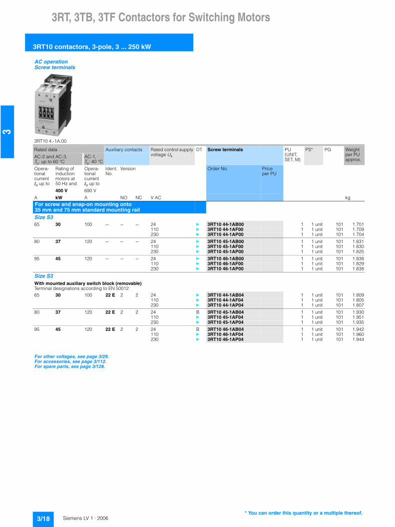
3RT, 3TB, 3TF Contactors for Switching Motors
3RT10 contactors, 3-pole, 3 ... 250 kW
3/18 Siemens LV 1 · 2006
3
AC operation Screw terminals
3RT10 4.-1A.00
Rated data Auxiliary contacts Rated control supply voltage Us
DT Screw terminals PU (UNIT, SET, M)
PS* PG Weight per PU approx.
AC-2 and AC-3, Tu: up to 60 °C
AC-1,Tu: 40 °C
Opera-tional current Ie up to
Rating of induction motors at 50 Hz and
Opera-tional current Ie up to
Ident. No.
Version Order No. Price per PU
400 V 690 V
A kW A NO NC V AC kgFor screw and snap-on mounting onto 35 mm and 75 mm standard mounting railSize S3 65 30 100 -- -- -- 24 } 3RT10 44-1AB00 1 1 unit 101 1.701
110 } 3RT10 44-1AF00 1 1 unit 101 1.709230 } 3RT10 44-1AP00 1 1 unit 101 1.704
80 37 120 -- -- -- 24 } 3RT10 45-1AB00 1 1 unit 101 1.831110 } 3RT10 45-1AF00 1 1 unit 101 1.830230 } 3RT10 45-1AP00 1 1 unit 101 1.825
95 45 120 -- -- -- 24 } 3RT10 46-1AB00 1 1 unit 101 1.838110 } 3RT10 46-1AF00 1 1 unit 101 1.829230 } 3RT10 46-1AP00 1 1 unit 101 1.838
Size S3 With mounted auxiliary switch block (removable) Terminal designations according to EN 5001265 30 100 22 E 2 2 24 } 3RT10 44-1AB04 1 1 unit 101 1.809
110 } 3RT10 44-1AF04 1 1 unit 101 1.805230 } 3RT10 44-1AP04 1 1 unit 101 1.807
80 37 120 22 E 2 2 24 B 3RT10 45-1AB04 1 1 unit 101 1.930110 } 3RT10 45-1AF04 1 1 unit 101 1.951230 } 3RT10 45-1AP04 1 1 unit 101 1.935
95 45 120 22 E 2 2 24 B 3RT10 46-1AB04 1 1 unit 101 1.942110 } 3RT10 46-1AF04 1 1 unit 101 1.960230 } 3RT10 46-1AP04 1 1 unit 101 1.944
For other voltages, see page 3/29.For accessories, see page 3/112.For spare parts, see page 3/128.
* You can order this quantity or a multiple thereof.

3RT, 3TB, 3TF Contactors for Switching Motors
3RT10 contactors, 3-pole, 3 ... 250 kW
3/19Siemens LV 1 · 2006
3
AC operationCage Clamp terminals
3RT10 4.-3A.00
Rated data Auxiliary contacts Rated control supply voltage Us at 50 Hz
DT Cage Clamp terminals for coil connections
PU (UNIT, SET, M)
PS* PG Weight per PU approx.
AC-2 and AC-3, Tu: up to 60 °C
AC-1,Tu: 40 °C
Opera-tional current Ie up to
Rating of induction motors at 50 Hz and
Opera-tional current Ie up to
Ident. No.
Version Order No. Price per PU
500 V 400 V 690 V
A kW A NO NC V AC kgFor screw and snap-on mounting onto 35 mm and 75 mm standard mounting railSize S3 65 30 100 -- -- -- 24 B 3RT10 44-3AB00 1 1 unit 101 1.720
110 B 3RT10 44-3AF00 1 1 unit 101 1.715230 } 3RT10 44-3AP00 1 1 unit 101 1.695
80 37 120 -- -- -- 24 B 3RT10 45-3AB00 1 1 unit 101 1.845110 B 3RT10 45-3AF00 1 1 unit 101 1.848230 } 3RT10 45-3AP00 1 1 unit 101 1.815
95 45 120 -- -- -- 24 B 3RT10 46-3AB00 1 1 unit 101 1.854110 B 3RT10 46-3AF00 1 1 unit 101 1.843230 } 3RT10 46-3AP00 1 1 unit 101 1.840
For other voltages, see page 3/29.For accessories, see page 3/112. For spare parts, see page 3/129.
* You can order this quantity or a multiple thereof.

3RT, 3TB, 3TF Contactors for Switching Motors
3RT10 contactors, 3-pole, 3 ... 250 kW
3/20 Siemens LV 1 · 2006
3
DC operation · DC solenoid systemScrew terminals
3RT10 1.-1B...
Rated data Auxiliary contacts Rated control supply voltage Us
DT Screw terminals PU (UNIT, SET, M)
PS* PG Weight per PU approx.
AC-2 and AC-3, Tu: up to 60 °C
AC-1,Tu: 40 °C
Opera-tional current Ie up to
Rating of induction motors at 50 Hz and
Opera-tional current Ie up to
Ident. No.
Version Order No. Price per PU
400 V 400 V 690 V
A kW A NO NC AC V kgFor screw and snap-on mounting onto 35 mm standard mounting railSize S00 Terminal designations according to EN 500127 3 18 10 E 1 -- 24 } 3RT10 15-1BB41 1 1 unit 101 0.263
220 A 3RT10 15-1BM41 1 1 unit 101 0.260
01 -- 1 24 } 3RT10 15-1BB42 1 1 unit 101 0.262220 B 3RT10 15-1BM42 1 1 unit 101 0.261
9 4 22 10 E 1 -- 24 } 3RT10 16-1BB41 1 1 unit 101 0.264220 B 3RT10 16-1BM41 1 1 unit 101 0.260
01 -- 1 24 } 3RT10 16-1BB42 1 1 unit 101 0.263220 B 3RT10 16-1BM42 1 1 unit 101 0.261
12 5.5 22 10 E 1 -- 24 } 3RT10 17-1BB41 1 1 unit 101 0.263220 B 3RT10 17-1BM41 1 1 unit 101 0.259
01 -- 1 24 } 3RT10 17-1BB42 1 1 unit 101 0.262220 B 3RT10 17-1BM42 1 1 unit 101 0.260
Size S00 With permanently mounted auxiliary switch block Terminal designations according to EN 500127 3 18 22 E 2 2 24 } 3RT10 15-1BB44-3MA0 1 1 unit 101 0.308
9 4 22 22 E 2 2 24 } 3RT10 16-1BB44-3MA0 1 1 unit 101 0.309
12 5.5 22 22 E 2 2 24 } 3RT10 17-1BB44-3MA0 1 1 unit 101 0.304
For other voltages, see page 3/29.For accessories, see page 3/110.For multi-unit packing and reusable packaging, see Appendix -> Ordering Notes.
* You can order this quantity or a multiple thereof.

3RT, 3TB, 3TF Contactors for Switching Motors
3RT10 contactors, 3-pole, 3 ... 250 kW
3/21Siemens LV 1 · 2006
3
DC operation · DC solenoid systemCage Clamp terminals
3RT10 1.-2B...
3RT10 1.-2BB44-3MA0
Rated data Auxiliary contacts Rated control supply voltage Us
DT Cage Clamp terminals PU (UNIT, SET, M)
PS* PG Weight per PU approx.
AC-2 and AC-3, Tu up to 60 °C
AC-1,Tu: 40 °C
Opera-tional current Ie up to
Rating of induction motors at 50 Hz and
Opera-tional current Ie up to
Ident. No.
Version Order No. Price per PU
400 V 400 V 690 V
A kW A NO NC V DC kgFor screw and snap-on mounting onto 35 mm standard mounting railSize S00 Terminal designations according to EN 500127 3 18 10 E 1 -- 24 } 3RT10 15-2BB41 1 1 unit 101 0.260
220 B 3RT10 15-2BM41 1 1 unit 101 0.252
01 -- 1 24 } 3RT10 15-2BB42 1 1 unit 101 0.261220 B 3RT10 15-2BM42 1 1 unit 101 0.256
9 4 22 10 E 1 -- 24 } 3RT10 16-2BB41 1 1 unit 101 0.259220 B 3RT10 16-2BM41 1 1 unit 101 0.253
01 -- 1 24 } 3RT10 16-2BB42 1 1 unit 101 0.261220 B 3RT10 16-2BM42 1 1 unit 101 0.253
12 5.5 22 10 E 1 -- 24 } 3RT10 17-2BB41 1 1 unit 101 0.261220 B 3RT10 17-2BM41 1 1 unit 101 0.254
01 -- 1 24 } 3RT10 17-2BB42 1 1 unit 101 0.261220 B 3RT10 17-2BM42 1 1 unit 101 0.255
Size S00 With permanently mounted auxiliary switch block Terminal designations according to EN 500127 3 18 22 E 2 2 24 B 3RT10 15-2BB44-3MA0 1 1 unit 101 0.308
9 4 22 22 E 2 2 24 A 3RT10 16-2BB44-3MA0 1 1 unit 101 0.308
12 5.5 22 22 E 2 2 24 B 3RT10 17-2BB44-3MA0 1 1 unit 101 0.308
For other voltages, see page 3/29.For accessories, see page 3/110.For multi-unit packing and reusable packaging, see Appendix -> Ordering Notes.
* You can order this quantity or a multiple thereof.

3RT, 3TB, 3TF Contactors for Switching Motors
3RT10 contactors, 3-pole, 3 ... 250 kW
3/22 Siemens LV 1 · 2006
3
1) Minimum conductor cross-section 10 mm².
DC operation · DC solenoid systemScrew terminals
3RT10 2.-1B0.40 3RT10 2.-1BB44-3MA0
Rated data Auxiliary contacts Rated control supply voltage Us
DT Screw terminals PU (UNIT, SET, M)
PS* PG Weight per PU approx.
AC-2 and AC-3, Tu: up to 60 °C
AC-1,Tu: 40 °C
Opera-tional current Ie up to
Rating of induction motors at 50 Hz and
Opera-tional current Ie up to
Ident. No.
Version Order No. Price per PU
400 V 400 V 690 V
A kW A NO NC V DC kgFor screw and snap-on mounting onto 35 mm standard mounting railsSize S0 9 4 401) -- -- -- 24 } 3RT10 23-1BB40 1 1 unit 101 0.570
220 B 3RT10 23-1BM40 1 1 unit 101 0.576
12 5.5 401) -- -- -- 24 } 3RT10 24-1BB40 1 1 unit 101 0.566220 A 3RT10 24-1BM40 1 1 unit 101 0.579
17 7.5 401) -- -- -- 24 } 3RT10 25-1BB40 1 1 unit 101 0.570220 A 3RT10 25-1BM40 1 1 unit 101 0.575
25 11 401) -- -- -- 24 } 3RT10 26-1BB40 1 1 unit 101 0.569220 A 3RT10 26-1BM40 1 1 unit 101 0.580
Size S0 With mounted auxiliary switch block (removable) Terminal designations according to EN 500129 4 401) 22 E 2 2 24 } 3RT10 23-1BB44 1 1 unit 101 0.639
220 B 3RT10 23-1BM44 1 1 unit 101 0.644
12 5.5 401) 22 E 2 2 24 } 3RT10 24-1BB44 1 1 unit 101 0.641220 B 3RT10 24-1BM44 1 1 unit 101 0.645
17 7.5 401) 22 E 2 2 24 } 3RT10 25-1BB44 1 1 unit 101 0.640220 B 3RT10 25-1BM44 1 1 unit 101 0.645
25 11 401) 22 E 2 2 24 } 3RT10 26-1BB44 1 1 unit 101 0.643220 B 3RT10 26-1BM44 1 1 unit 101 0.645
Size S0 With permanently mounted auxiliary switch block Terminal designations according to EN 5001212 5.5 401) 22 E 2 2 24 A 3RT10 24-1BB44-3MA0 1 1 unit 101 0.641
17 7.5 401) 22 E 2 2 24 A 3RT10 25-1BB44-3MA0 1 1 unit 101 0.640
25 11 401) 22 E 2 2 24 A 3RT10 26-1BB44-3MA0 1 1 unit 101 0.642
For other voltages, see page 3/29.For accessories, see page 3/112.For multi-unit packing and reusable packaging, see Appendix -> Ordering Notes.
* You can order this quantity or a multiple thereof.

3RT, 3TB, 3TF Contactors for Switching Motors
3RT10 contactors, 3-pole, 3 ... 250 kW
3/23Siemens LV 1 · 2006
3
1) Minimum conductor cross-section 10 mm².
DC operation · DC solenoid systemCage Clamp terminals
3RT10 2.-3B.40
Rated data Auxiliary contacts Rated control supply voltage Us
DT Cage Clamp terminals PU (UNIT, SET, M)
PS* PG Weight per PU approx.
AC-2 and AC-3, Tu: up to 60 °C
AC-1,Tu: 40 °C
Opera-tional current Ie up to
Rating of induction motors at 50 Hz and
Opera-tional current Ie up to
Ident. No.
Version Order No. Price per PU
400 V 400 V 690 V
A kW A NO NC V DC kgFor screw and snap-on mounting onto 35 mm standard mounting railSize S0 9 4 401) -- -- -- 24 } 3RT10 23-3BB40 1 1 unit 101 0.566
-- -- -- 220 B 3RT10 23-3BM40 1 1 unit 101 0.572
12 5.5 401) -- -- -- 24 } 3RT10 24-3BB40 1 1 unit 101 0.568-- -- -- 220 B 3RT10 24-3BM40 1 1 unit 101 0.570
17 7.5 401) -- -- -- 24 } 3RT10 25-3BB40 1 1 unit 101 0.570-- -- -- 220 B 3RT10 25-3BM40 1 1 unit 101 0.572
25 11 401) -- -- -- 24 } 3RT10 26-3BB40 1 1 unit 101 0.569-- -- -- 220 B 3RT10 26-3BM40 1 1 unit 101 0.575
For other voltages, see page 3/29.For accessories, see page 3/112.For multi-unit packing and reusable packaging, see Appendix -> Ordering Notes.
* You can order this quantity or a multiple thereof.

3RT, 3TB, 3TF Contactors for Switching Motors
3RT10 contactors, 3-pole, 3 ... 250 kW
3/24 Siemens LV 1 · 2006
3
DC operation · DC solenoid system Screw terminals
3RT10 3.-1B.40 3RT10 4.-1B.40 3RT10 4.-1B.44
Rated data Auxiliary contacts Rated control supply voltage Us
DT Screw terminals PU (UNIT, SET, M)
PS* PG Weight per PU approx.
AC-2 and AC-3, Tu: up to 60 °C
AC-1,Tu: 40 °C
Opera-tional current Ie up to
Ratings of induction motors at 50 Hz and
Opera-tional current Ie up to
Ident. No.
Version Order No. Price per PU
500 V 400 V 690 V
A kW A NO NC V DC kgFor screw and snap-on mounting onto 35 mm standard mounting railSize S2 32 15 50 -- -- -- 24 } 3RT10 34-1BB40 1 1 unit 101 1.433
220 A 3RT10 34-1BM40 1 1 unit 101 1.446
40 18.5 60 -- -- -- 24 } 3RT10 35-1BB40 1 1 unit 101 1.443220 B 3RT10 35-1BM40 1 1 unit 101 1.439
50 22 60 -- -- -- 24 } 3RT10 36-1BB40 1 1 unit 101 1.435220 B 3RT10 36-1BM40 1 1 unit 101 1.444
Size S2 With mounted auxiliary switch block (removable) Terminal designations according to EN 5001232 15 50 22 E 2 2 24 } 3RT10 34-1BB44 1 1 unit 101 1.530
220 A 3RT10 34-1BM44 1 1 unit 101 1.530
40 18.5 60 22 E 2 2 24 } 3RT10 35-1BB44 1 1 unit 101 1.522220 B 3RT10 35-1BM44 1 1 unit 101 1.523
50 22 60 22 E 2 2 24 } 3RT10 36-1BB44 1 1 unit 101 1.533220 B 3RT10 36-1BM44 1 1 unit 101 1.508
For screw and snap-on mounting onto 35 mm and 75 mm standard mounting railSize S3 65 30 100 -- -- -- 24 } 3RT10 44-1BB40 1 1 unit 101 2.808
220 B 3RT10 44-1BM40 1 1 unit 101 2.793
80 37 120 -- -- -- 24 } 3RT10 45-1BB40 1 1 unit 101 2.828220 B 3RT10 45-1BM40 1 1 unit 101 2.781
95 45 120 -- -- -- 24 } 3RT10 46-1BB40 1 1 unit 101 2.817220 B 3RT10 46-1BM40 1 1 unit 101 2.767
Size S3 With mounted auxiliary switch block (removable) Terminal designations according to EN 5001265 30 100 22 E 2 2 24 } 3RT10 44-1BB44 1 1 unit 101 2.921
220 B 3RT10 44-1BM44 1 1 unit 101 2.880
80 37 120 22 E 2 2 24 } 3RT10 45-1BB44 1 1 unit 101 2.919220 B 3RT10 45-1BM44 1 1 unit 101 2.870
95 45 120 22 E 2 2 24 } 3RT10 46-1BB44 1 1 unit 101 2.913220 B 3RT10 46-1BM44 1 1 unit 101 2.887
For other voltages, see page 3/29.For accessories, see page 3/112. For spare parts, see page 3/128.For multi-unit packing and reusable packaging, see Appendix -> Ordering Notes.
* You can order this quantity or a multiple thereof.

3RT, 3TB, 3TF Contactors for Switching Motors
3RT10 contactors, 3-pole, 3 ... 250 kW
3/25Siemens LV 1 · 2006
3
DC operation · DC solenoid systemCage Clamp terminals
3RT10 3.-3B.40 3RT10 4.-3B.40
Rated data Auxiliary contacts Rated control supply voltage Us
DT Cage Clamp terminals PU (UNIT, SET, M)
PS* PG Weight per PU approx.
AC-2 and AC-3, Tu: up to 60 °C
AC-1,Tu: 40 °C
Opera-tional current Ie up to
Rating of induction motors at 50 Hz and
Opera-tional current Ie up to
Ident. No.
Version Order No. Price per PU
500 V 400 V 690 V
A kW A NO NC V DCFor screw and snap-on mounting onto 35 mm standard mounting railSize S2 32 15 50 -- -- -- 24 } 3RT10 34-3BB40 1 1 unit 101 1.435
220 B 3RT10 34-3BM40 1 1 unit 101 1.452
40 18.5 60 -- -- -- 24 } 3RT10 35-3BB40 1 1 unit 101 1.426220 B 3RT10 35-3BM40 1 1 unit 101 1.454
50 22 60 -- -- -- 24 } 3RT10 36-3BB40 1 1 unit 101 1.443220 A 3RT10 36-3BM40 1 1 unit 101 1.455
For screw and snap-on mounting onto 35 mm and 75 mm standard mounting railSize S3 65 30 100 -- -- -- 24 } 3RT10 44-3BB40 1 1 unit 101 2.807
220 B 3RT10 44-3BM40 1 1 unit 101 2.749
80 37 120 -- -- -- 24 } 3RT10 45-3BB40 1 1 unit 101 2.807220 B 3RT10 45-3BM40 1 1 unit 101 2.770
95 45 120 -- -- -- 24 } 3RT10 46-3BB40 1 1 unit 101 2.821220 B 3RT10 46-3BM40 1 1 unit 101 2.760
For other voltages, see page 3/29.For accessories, see page 3/112. For spare parts, see page 3/129.For multi-unit packing and reusable packaging, see Appendix -> Ordering Notes.
* You can order this quantity or a multiple thereof.

3RT, 3TB, 3TF Contactors for Switching Motors
3RT10 contactors, 3-pole, 3 ... 250 kW
3/26 Siemens LV 1 · 2006
3
1) Alternatively the 3RT10 54-1 contactor (55 kW) can be supplied with bar connections instead of box terminals. Without additional charge. In the 8th position of the Order No. the "1" must be replaced with "6", e.g. 3RT10 54-6..
AC/DC operation (40 Hz to 60 Hz, DC) Auxiliary and control conductors: screw terminalsWithdrawable coils Integrated coil circuit (varistor)Main conductors: bar connections, for 3RT10 54 (55 kW) box terminals1)
3RT1. 5. 3RT1. 6. 3RT1. 7.
Size Rated data Auxiliary contacts, lateral
Rated control supply voltage Us
DT Screw terminals PU (UNIT, SET, M)
PS* PG Weight per PU approx.
AC-2 and AC-3, Tu: up to 60 °C
AC-1,Tu: 40 °C
Opera-tional current Ie up to
Ratings of induction motors at 50 Hz and
Opera-tional current Ie up to
Order No. Price per PU
500 V 230 V 400 V 500 V 690 V 690 V
A kW kW kW kW A NO NC V AC/DC kgConventional operating mechanismS6 115 37 55 75 110 160 2 2 110 … 127 } 3RT10 54-1AF36 1 1 unit 101 3.641
220 … 240 } 3RT10 54-1AP36 1 1 unit 101 3.619
150 45 75 90 132 185 2 2 110 … 127 } 3RT10 55-6AF36 1 1 unit 101 3.344220 … 240 } 3RT10 55-6AP36 1 1 unit 101 3.331
185 55 90 110 160 215 2 2 110 … 127 } 3RT10 56-6AF36 1 1 unit 101 3.369220 … 240 } 3RT10 56-6AP36 1 1 unit 101 3.350
S10 225 55 110 160 200 275 2 2 110 … 127 } 3RT10 64-6AF36 1 1 unit 101 6.508220 … 240 } 3RT10 64-6AP36 1 1 unit 101 6.428
265 75 132 160 250 330 2 2 110 … 127 } 3RT10 65-6AF36 1 1 unit 101 6.554220 … 240 } 3RT10 65-6AP36 1 1 unit 101 6.500
300 90 160 200 250 330 2 2 110 … 127 } 3RT10 66-6AF36 1 1 unit 101 6.599220 … 240 } 3RT10 66-6AP36 1 1 unit 101 6.520
S12 400 132 200 250 400 430 2 2 110 … 127 } 3RT10 75-6AF36 1 1 unit 101 10.340220 … 240 } 3RT10 75-6AP36 1 1 unit 101 10.070
500 160 250 355 400 610 2 2 110 … 127 } 3RT10 76-6AF36 1 1 unit 101 10.490220 … 240 } 3RT10 76-6AP36 1 1 unit 101 10.355
Solid-state operating mechanism · for 24 V DC PLC output S6 115 37 55 75 110 160 2 2 96 … 127 A 3RT10 54-1NF36 1 1 unit 101 3.630
200 … 277 } 3RT10 54-1NP36 1 1 unit 101 3.950
150 45 75 90 132 185 2 2 96 … 127 A 3RT10 55-6NF36 1 1 unit 101 3.325200 … 277 } 3RT10 55-6NP36 1 1 unit 101 3.325
185 55 90 110 160 215 2 2 96 … 127 A 3RT10 56-6NF36 1 1 unit 101 3.335200 … 277 } 3RT10 56-6NP36 1 1 unit 101 3.334
S10 225 55 110 160 200 275 2 2 96 … 127 A 3RT10 64-6NF36 1 1 unit 101 6.664200 … 277 A 3RT10 64-6NP36 1 1 unit 101 6.526
265 75 132 160 250 330 2 2 96 … 127 A 3RT10 65-6NF36 1 1 unit 101 6.711200 … 277 A 3RT10 65-6NP36 1 1 unit 101 6.600
300 90 160 200 250 330 2 2 96 … 127 B 3RT10 66-6NF36 1 1 unit 101 6.720200 … 277 A 3RT10 66-6NP36 1 1 unit 101 6.600
S12 400 132 200 250 400 430 2 2 96 … 127 A 3RT10 75-6NF36 1 1 unit 101 10.352200 … 277 A 3RT10 75-6NP36 1 1 unit 101 10.079
500 160 250 355 400 610 2 2 96 … 127 A 3RT10 76-6NF36 1 1 unit 101 10.501200 … 277 A 3RT10 76-6NP36 1 1 unit 101 10.235
For other voltages, see page 3/29.For accessories, see page 3/112. For spare parts, see page 3/130.
* You can order this quantity or a multiple thereof.

3RT, 3TB, 3TF Contactors for Switching Motors
3RT10 contactors, 3-pole, 3 ... 250 kW
3/27Siemens LV 1 · 2006
3
1) Alternatively the 3RT10 54-1 contactor (55 kW) can be supplied with bar connections instead of box terminals. Without additional charge. In the 8th position of the Order No. the "3" must be replaced with "2", e.g. 3RT10 54-2...
AC/DC operation (40 Hz to 60 Hz, DC)Auxiliary and control conductors: Cage Clamp terminalsWithdrawable coils Integrated coil circuit (varistor)Main conductors: bar connections, for 3RT10 54 (55 kW) box terminals1)
Size Rated data Auxiliary contacts, lateral
Rated control supply voltage Us
DT Cage Clamp terminals PU (UNIT, SET, M)
PS* PG Weight per PU approx.
AC-2 and AC-3, Tu: up to 60 °C
AC-1,Tu: 40 °C
Opera-tional current Ie up to
Ratings of induction motors at 50 Hz and
Opera-tional current Ie up to
Order No. Price per PU
500 V 230 V 400 V 500 V 690 V 690 V
A kW kW kW kW A NO NC V AC/DC kgConventional operating mechanismS6 115 37 55 75 110 160 2 2 110 … 127 B 3RT10 54-3AF36 1 1 unit 101 3.641
220 … 240 B 3RT10 54-3AP36 1 1 unit 101 3.628
150 45 75 90 132 185 2 2 110 … 127 B 3RT10 55-2AF36 1 1 unit 101 3.344220 … 240 B 3RT10 55-2AP36 1 1 unit 101 3.332
185 55 90 110 160 215 2 2 110 … 127 B 3RT10 56-2AF36 1 1 unit 101 3.374220 … 240 B 3RT10 56-2AP36 1 1 unit 101 3.350
S10 225 55 110 160 200 275 2 2 110 … 127 B 3RT10 64-2AF36 1 1 unit 101 6.508220 … 240 B 3RT10 64-2AP36 1 1 unit 101 6.428
265 75 132 160 250 330 2 2 110 … 127 B 3RT10 65-2AF36 1 1 unit 101 6.554220 … 240 B 3RT10 65-2AP36 1 1 unit 101 6.500
300 90 160 200 250 330 2 2 110 … 127 B 3RT10 66-2AF36 1 1 unit 101 6.599220 … 240 B 3RT10 66-2AP36 1 1 unit 101 6.520
S12 400 132 200 250 400 430 2 2 110 … 127 B 3RT10 75-2AF36 1 1 unit 101 10.340220 … 240 B 3RT10 75-2AP36 1 1 unit 101 10.070
500 160 250 355 400 610 2 2 110 … 127 B 3RT10 76-2AF36 1 1 unit 101 10.490220 … 240 B 3RT10 76-2AP36 1 1 unit 101 10.366
Solid-state operating mechanism · for 24 V DC PLC output S6 115 37 55 75 110 160 2 2 96 … 127 B 3RT10 54-3NF36 1 1 unit 101 3.630
200 … 277 B 3RT10 54-3NP36 1 1 unit 101 3.950
150 45 75 90 132 185 2 2 96 … 127 B 3RT10 55-2NF36 1 1 unit 101 3.325200 … 277 B 3RT10 55-2NP36 1 1 unit 101 3.325
185 55 90 110 160 215 2 2 96 … 127 B 3RT10 56-2NF36 1 1 unit 101 3.335200 … 277 B 3RT10 56-2NP36 1 1 unit 101 3.335
S10 225 55 110 160 200 275 2 2 96 … 127 B 3RT10 64-2NF36 1 1 unit 101 6.664200 … 277 B 3RT10 64-2NP36 1 1 unit 101 6.526
265 75 132 160 250 330 2 2 96 … 127 B 3RT10 65-2NF36 1 1 unit 101 6.711200 … 277 B 3RT10 65-2NP36 1 1 unit 101 6.600
300 90 160 200 250 330 2 2 96 … 127 B 3RT10 66-2NF36 1 1 unit 101 6.720200 … 277 B 3RT10 66-2NP36 1 1 unit 101 6.600
S12 400 132 200 250 400 430 2 2 96 … 127 B 3RT10 75-2NF36 1 1 unit 101 10.352200 … 277 B 3RT10 75-2NP36 1 1 unit 101 10.079
500 160 250 355 400 610 2 2 96 … 127 B 3RT10 76-2NF36 1 1 unit 101 10.501200 … 277 B 3RT10 76-2NP36 1 1 unit 101 10.235
For other voltages, see page 3/29.For accessories, see page 3/112. For spare parts, see page 3/131.
* You can order this quantity or a multiple thereof.

3RT, 3TB, 3TF Contactors for Switching Motors
3RT10 contactors, 3-pole, 3 ... 250 kW
3/28 Siemens LV 1 · 2006
3
1) Alternatively the 3RT10 54-1 contactor (55 kW) can be supplied with bar connections instead of box terminals. Without additional charge. In the 8th position of the Order No. the "1" must be replaced with "6", e.g. 3RT10 54-6...
AC/DC operation (40 Hz to 60 Hz, DC) Auxiliary and control conductors: screw terminalsWithdrawable coils Integrated coil circuit (varistor)Main conductors: bar connections, for 3RT10 54 (55 kW) box terminals1) Remaining lifetime indication (RLT)
3RT10 56-6P
3RT10 56-6Q
Size Rated data Auxiliary contacts, lateral
Rated control supply voltage Us
DT Screw terminals PU (UNIT, SET, M)
PS* PG Weight per PU approx.
AC-2 and AC-3, Tu: up to 60 °C
AC-1,Tu: 40 °C
Opera-tional current Ie up to
Ratings of induction motors at 50 Hz and
Opera-tional current Ie up to
Order No. Price per PU
500 V 230 V 400 V 500 V 690 V 690 V
A kW kW kW kW A NO NC V AC/DC kgSolid-state operating mechanism · for 24 V DC PLC output/PLC relay output, with indication of remaining lifetime (RLT) S6 115 37 55 75 110 160 1 1 96 … 127 B 3RT10 54-1PF35 1 1 unit 101 4.200
200 … 277 B 3RT10 54-1PP35 1 1 unit 101 4.440
150 45 75 90 132 185 1 1 96 … 127 B 3RT10 55-6PF35 1 1 unit 101 3.875200 … 277 B 3RT10 55-6PP35 1 1 unit 101 3.884
185 55 90 110 160 215 1 1 96 … 127 B 3RT10 56-6PF35 1 1 unit 101 3.913200 … 277 B 3RT10 56-6PP35 1 1 unit 101 4.093
S10 225 55 110 160 200 275 1 1 96 … 127 B 3RT10 64-6PF35 1 1 unit 101 5.700200 … 277 B 3RT10 64-6PP35 1 1 unit 101 6.960
265 75 132 160 250 330 1 1 96 … 127 B 3RT10 65-6PF35 1 1 unit 101 7.203200 … 277 B 3RT10 65-6PP35 1 1 unit 101 7.004
300 90 160 200 250 330 1 1 96 … 127 B 3RT10 66-6PF35 1 1 unit 101 4.852200 … 277 B 3RT10 66-6PP35 1 1 unit 101 7.050
S12 400 132 200 250 400 430 1 1 96 … 127 B 3RT10 75-6PF35 1 1 unit 101 10.781200 … 277 B 3RT10 75-6PP35 1 1 unit 101 10.505
500 160 250 355 400 610 1 1 96 … 127 B 3RT10 76-6PF35 1 1 unit 101 9.100200 … 277 B 3RT10 76-6PP35 1 1 unit 101 10.665
Solid-state operating mechanism · with AS-Interface and indication of remaining lifetime (RLT) S6 115 37 55 75 110 160 1 1 96 … 127 B 3RT10 54-1QF35 1 1 unit 101 4.190
200 … 277 B 3RT10 54-1QP35 1 1 unit 101 4.167
150 45 75 90 132 185 1 1 96 … 127 B 3RT10 55-6QF35 1 1 unit 101 3.892200 … 277 B 3RT10 55-6QP35 1 1 unit 101 3.886
185 55 90 110 160 215 1 1 96 … 127 B 3RT10 56-6QF35 1 1 unit 101 3.100200 … 277 B 3RT10 56-6QP35 1 1 unit 101 3.888
S10 225 55 110 160 200 275 1 1 96 … 127 B 3RT10 64-6QF35 1 1 unit 101 7.018200 … 277 B 3RT10 64-6QP35 1 1 unit 101 6.930
265 75 132 160 250 330 1 1 96 … 127 B 3RT10 65-6QF35 1 1 unit 101 5.70000 … 277 B 3RT10 65-6QP35 1 1 unit 101 7.000
300 90 160 200 250 330 1 1 96 … 127 B 3RT10 66-6QF35 1 1 unit 101 5.700200 … 277 B 3RT10 66-6QP35 1 1 unit 101 7.018
S12 400 132 200 250 400 430 1 1 96 … 127 B 3RT10 75-6QF35 1 1 unit 101 9.100200 … 277 B 3RT10 75-6QP35 1 1 unit 101 10.513
500 160 250 355 400 610 1 1 96 … 127 B 3RT10 76-6QF35 1 1 unit 101 11.730200 … 277 B 3RT10 76-6QP35 1 1 unit 101 9.100
For other voltages, see page 3/29.For accessories, see page 3/112.For spare parts, see page 3/130.
* You can order this quantity or a multiple thereof.

3RT, 3TB, 3TF Contactors for Switching Motors
3RT10 contactors, 3-pole, 3 ... 250 kW
3/29Siemens LV 1 · 2006
3
Rated control supply voltages
1) For deviating coil voltages and coil operating ranges of sizes S00 and S0, the 24 V DC SITOP Power power supply with wide range input (93 to 264 V AC; 30 to 264 V DC) can be used for coil excitation (see Power Supplies -> SITOP Power Power Supplies).
2) Coil operating rangeat 50 Hz: 0.8 to 1.1 x Usat 60 Hz: 0.85 to 1.1 x Us
3) Coil operating rangeSize S00: at 50 Hz: 0.85 to 1.1 x Us
at 60 Hz: 0.8 to 1.1 x UsSizes S0 to S3: at 50 Hz and 60 Hz: 0.8 to 1.1 x Us
4) Coil operating rangeSize S00: at 50/60 Hz: 0.85 to 1.1 x UsSizes S0 to S3: at 50 Hz: 0.8 to 1.1 x Us
at 60 Hz: 0.85 to 1.1 x Us
5) Coil operating rangeat 60 Hz: 0.8 to 1.1 x Us
6) Operating range:0.8 x Us min to 1.1 x Us max
Contactor type 3RT10 1 3RT10 2,3RT10 3,
3RT10 4
3RT14 4 3RT13 1,
3RT15 1
3RT13 2 to 3RT13 4,
3RT15 2 and 3RT15 3
3RT16
Rated control supply voltage Us
Rated control supply voltages (the 10th and 11th position of the order number must be changed)
Sizes S00 ... S3 AC operation1)
Coils for 50 Hz (exception: size S00: 50 and 60 Hz2))
24 V AC B0 B0 B0 B0 B0 B0 42 V AC D0 D0 D0 D0 -- -- 48 V AC H0 H0 H0 H0 -- --
110 V AC F0 F0 F0 F0 F0 F0230 V AC P0 P0 P0 P0 P0 P0400 V AC V0 V0 V0 V0 V0 V0
Coils for 50 and 60 Hz2)
24 V AC B0 C2 C2 B0 C2 C2 42 V AC D0 D2 D2 D0 D2 -- 48 V AC H0 H2 H2 H0 H2 --
110 V AC F0 G2 G2 F0 G2 G2220 V AC N2 N2 N2 N2 N2 N2230 V AC P0 L2 L2 P0 L2 L2
For USA and Canada3)
50 Hz 60 Hz
110 V AC 120 V AC K6 K6 K6 K6 K6 K6220 V AC 240 V AC P6 P6 P6 P6 P6 P6
For Japan
50/60 Hz4) 60 Hz5)
100 V AC 110 V AC G6 G6 G6 G6 G6 G6200 V AC 220 V AC N6 N6 N6 N6 N6 N6400 V AC 440 V AC R6 R6 R6 R6 R6 R6
DC operation1)
12 V DC A4 -- -- A4 -- -- 24 V DC B4 B4 B4 B4 B4 -- 42 V DC D4 D4 D4 D4 D4 -- 48 V DC W4 W4 W4 W4 -- -- 60 V DC E4 E4 E4 -- -- --
110 V DC F4 F4 F4 F4 F4 --125 V DC G4 G4 G4 G4 G4 --220 V DC M4 M4 M4 M4 M4 --230 V DC P4 P4 P4 P4 -- --
Sizes S6 ... S12 AC/DC operation (40 ... 60 Hz, DC)
Conventional operating mechanism
Us min ... Us max6)
Contactor type 3RT1. 5.-.A3RT1. 6.-.A3RT1. 7.-.A
Us min ... Us max6)
Contactor type 3RT1. 5.-.A3RT1. 6.-.A3RT1. 7.-.A
23 ... 26 V AC/DC B3 240 ... 277 V AC/DC U342 ... 48 V AC/DC D3 380 ... 420 V AC/DC V3
110 ... 127 V AC/DC F3 440 ... 480 V AC/DC R3200 ... 220 V AC/DC M3 500 ... 550 V AC/DC S3220 ... 240 V AC/DC P3 575 ... 600 V AC/DC T3
Solid-state operating mechanism
Us min ... Us max6)
Contactor type 3RT1. 5.-.N3RT1. 6.-.N3RT1. 7.-.N
3RT1. 5.-.P/Q3RT1. 6.-.P/Q3RT1. 7.-.P/Q
21 ... 27.3 V AC/DC B3 --96 ... 127 V AC/DC F3 F3
200 ... 277 V AC/DC P3 P3

3RT, 3TB, 3TF Contactors for Switching Motors
3RT12 vacuum contactors, 3-pole, 110 ... 250 kW
3/30 Siemens LV 1 · 2006
3
■ Overview
• 3RT12 vacuum contactors for switching motors
Operating mechanism types
Two types of solenoid operation are available:• Conventional operating mechanism, version 3RT12 ..-.A• Solid-state operating mechanism, version 3RT12 ..-.N
UC operation
The contactors can be operated with AC (40 to 60 Hz) as well as with DC.
Withdrawable coils
For simple coil replacement, e.g. if the application is replaced, the magnetic coil can be pulled out upwards after the release mechanism has been actuated and can be replaced by any other coil of the same size.
Auxiliary contact complement
The contactors can be fitted with up to 8 laterally mounted auxiliary contacts (identical auxiliary switch blocks from S0 to S12). Of these, no more than 4 are permitted to be NC contacts.
■ Selection and ordering data
AC/DC operation (40 Hz to 60 Hz, DC) Auxiliary and control conductors: screw terminalsWithdrawable coils Integrated coil circuit (varistor)Main conductors: bar connections
3RT12 7.
3RT1
3RT12 7.
Size Rated data Auxiliary contacts, lateral
Rated control supply voltage Us
DT Order No. Price per PU
PU (UNIT, SET, M)
PS* PG Weight per PU approx.
AC-2 and AC-3, Tu: up to 60 °C
AC-1,Tu: 40 °C
Opera-tional current Ie up to
Ratings of induction motors at 50 Hz and
Opera-tional current Ie up to
1000 V 230 V 400 V 500 V 690 V 1000 V
A kW kW kW kW A NO NC V AC/DC kgConventional operating mechanismS10 225 55 110 160 200 330 2 2 110 … 127 A 3RT12 64-6AF36 1 1 unit 101 7.355
220 … 240 A 3RT12 64-6AP36 1 1 unit 101 7.225
265 75 132 160 250 330 2 2 110 … 127 A 3RT12 65-6AF36 1 1 unit 101 7.386220 … 240 A 3RT12 65-6AP36 1 1 unit 101 7.300
300 90 160 200 250 330 2 2 110 … 127 A 3RT12 66-6AF36 1 1 unit 101 7.331220 … 240 A 3RT12 66-6AP36 1 1 unit 101 7.318
S12 400 132 200 250 400 610 2 2 110 … 127 A 3RT12 75-6AF36 1 1 unit 101 10.500220 … 240 A 3RT12 75-6AP36 1 1 unit 101 10.397
500 160 250 355 500 610 2 2 110 … 127 A 3RT12 76-6AF36 1 1 unit 101 10.534220 … 240 A 3RT12 76-6AP36 1 1 unit 101 10.400
Solid-state operating mechanism · for 24 V DC PLC output S10 225 55 110 160 200 330 2 2 96 … 127 B 3RT12 64-6NF36 1 1 unit 101 7.400
200 … 277 B 3RT12 64-6NP36 1 1 unit 101 7.394
265 75 132 160 250 330 2 2 96 … 127 B 3RT12 65-6NF36 1 1 unit 101 7.400200 … 277 B 3RT12 65-6NP36 1 1 unit 101 7.399
300 90 160 200 250 330 2 2 96 … 127 B 3RT12 66-6NF36 1 1 unit 101 7.402200 … 277 B 3RT12 66-6NP36 1 1 unit 101 7.407
S12 400 132 200 250 400 610 2 2 96 … 127 B 3RT12 75-6NF36 1 1 unit 101 7.250200 … 277 B 3RT12 75-6NP36 1 1 unit 101 10.250
500 160 250 355 500 610 2 2 96 … 127 B 3RT12 76-6NF36 1 1 unit 101 10.580200 … 277 B 3RT12 76-6NP36 1 1 unit 101 10.246
For other voltages, see page 3/29.For more 3TF68/69 vacuum contactors (335 kW and 450 kW), see page 3/32.For accessories, see page 3/114.
* You can order this quantity or a multiple thereof.

3RT, 3TB, 3TF Contactors for Switching Motors
3TF6 vacuum contactors, 3-pole, 335 ... 450 kW
3/31Siemens LV 1 · 2006
3
■ Overview
IEC 60947-4-1, EN 60947-4-1 (VDE 0660 Part 102)
The 3TF68/69 contactors are climate-proof. They are finger-safe according to EN 50274. Terminal covers (see Accessories and Spare Parts, page 3/135) may have to be fitted onto the connecting bars, depending on the configuration with other devices.

3RT, 3TB, 3TF Contactors for Switching Motors
3TF6 vacuum contactors, 3-pole, 335 ... 450 kW
3/32 Siemens LV 1 · 2006
3
■ Selection and ordering data
1) Built-in overvoltage damping: varistor circuit. 2) For more information on EMC, see LV 1 T . 3TF68/69 vacuum contactors are supplied with integrated overvoltage damping for the main conducting paths (for description, see LV 1 T). The overvoltage damping circuit is not required if 3TF68/69 contactors are used in circuits with DC choppers, frequency converters or speed-variable drives, for example. It could be damaged by the voltage peaks and harmonics and cause phase-to-phase short-circuits. For this reason, the contactors can also be supplied without integrated voltage damping. Without additional charge. The order number must include "-Z" and the order code "A02".
Auxiliary and control conduct.: screw terminalsMain conductors: bar connections Size 14
3TF6. 33-.Q..
3TF68
Rated data Auxiliary contacts
Rated control supply voltage Us
DT Order No. Price per PU
PU (UNIT, SET, M)
PS* PG Weight per PU approx.
AC-2 and AC-3 (up to 55 °C) AC -1
Opera-tional current Ie up to 690 V
Ratings of induction motors at 50 Hz and
Opera-tional current Ie (at 40 °C)
Version
230 V 400 V 500 V 690 V 1000 V
A kW kW kW kW kW A NO NC V kg
AC operation1) 2) 630 200 335 434 600 -- 700 4 4 110 ... 132 AC,
50/60 Hz} 3TF68 44-0CF7 1 1 unit 101 19.364
200 ... 240 AC, 50/60 Hz
} 3TF68 44-0CM7 1 1 unit 101 19.820
630 200 335 434 600 600 700 4 4 110 ... 132 AC, 50/60 Hz
C 3TF68 44-8CF7 1 1 unit 101 19.670
200 ... 240 AC, 50/60 Hz
B 3TF68 44-8CM7 1 1 unit 101 20.270
820 260 450 600 800 -- 910 4 4 110 ... 132 AC, 50/60 Hz
A 3TF69 44-0CF7 1 1 unit 101 21.833
200 ... 240, 50/60 Hz
} 3TF69 44-0CM7 1 1 unit 101 22.105
820 260 450 600 800 800 910 4 4 110 ... 132 AC, 50/60 Hz
C 3TF69 44-8CF7 1 1 unit 101 22.307
200 ... 240 AC, 50/60 Hz
C 3TF69 44-8CM7 1 1 unit 101 22.454
DC operation � DC economy circuit630 200 335 434 600 -- 700 3 3 24 DC C 3TF68 33-1DB4 1 1 unit 101 19.532
600 C 3TF68 33-8DB4 1 1 unit 101 17.900
820 260 450 600 800 -- 910 3 3 24 DC C 3TF69 33-1DB4 1 1 unit 101 22.666800 C 3TF69 33-8DB4 1 1 unit 101 12.258
AC operation � Version for AC controls which are subj. to strong interference630 200 335 434 600 -- 700 3 3 110 ... 120 AC,
50/60 HzC 3TF68 33-1QG7 1 1 unit 101 18.592
220 ... 240 AC, 50/60 Hz
C 3TF68 33-1QL7 1 1 unit 101 21.100
380 ... 420 AC, 50/60 Hz
C 3TF68 33-1QV7 1 1 unit 101 20.739
600 700 3 3 110 ...120 AC, 50/60 Hz
C 3TF68 33-8QG7 1 1 unit 101 21.000
220 ... 240 AC, 50/60 Hz
C 3TF68 33-8QL7 1 1 unit 101 21.034
820 260 450 600 800 -- 910 3 3 110 ... 120 AC, 50/60 Hz
C 3TF69 33-1QG7 1 1 unit 101 22.512
220 ... 240 AC, 50/60 Hz
C 3TF69 33-1QL7 1 1 unit 101 22.400
380 ... 420 AC, 50/60 Hz
C 3TF69 33-1QV7 1 1 unit 101 22.625
800 910 3 3 110 ... 120 AC, 50/60 Hz
C 3TF69 33-8QG7 1 1 unit 101 21.900
220 ... 240 AC, 50/60 Hz
C 3TF69 33-8QL7 1 1 unit 101 22.897
Reversing contactors supplied: 3TC44 17-4A..
For accessories, see page 3/134, for spare parts, see page 3/144.
� �!��).
"
"
�
% �) � ( � 9 5% � = � � � !
0 � � � � 0 � � �) � ( � >
� � � !0 � � � � 0 � � � �� ! 4
� � � � � � !0 � � � � 0 � � �) �
* You can order this quantity or a multiple thereof.

3RT, 3TB, 3TF Contactors for Switching Motors
3TF6 vacuum contactors, 3-pole, 335 ... 450 kW
3/33Siemens LV 1 · 2006
3
Rated control supply voltages
Contactor Type 3TF3TF68..-.C/D 3TF69..-.C/D
Rated control supply voltages (the 10th and 11th position of the order number must be changed)
AC operation · Magnetic coils for 50/60 Hz110 ... 132 V AC F7200 ... 240 V AC M7230 ... 277 V AC P7
380 ... 460 V AC Q7500 ... 600 V AC S7
DC operation24 V DC B4
110 V DC F4
125 V DC G4220 V DC M4
230 V DC P4

3RT, 3TB, 3TF Contactors for Switching Motors
3TB5 contactors with DC solenoid system,3-pole, 55 ... 200 kW
3/34 Siemens LV 1 · 2006
3
■ Selection and ordering data
Auxiliary and control conductors: screw terminalsMain conductors: bar connections
3TB50
Size Rated data Auxiliary contacts
Rated control supply voltage Us
DT Order No. Price per PU
PU (UNIT, SET, M)
PS* PG Weight per PU approx.
AC-2 and AC-3 (up to 55 °C) AC -1
Opera-tional cur-rent Ie up to
Ratings of induction motors at 50 Hz and
Opera-tional cur-rent Ie (at 40 °C)
Version
690 V 230 V 400 V 500 V 690 V
A kW kW kW kW A NO NC V DC kgDC operation � DC solenoid system6 110 37 55 75 90 170 2 2 24 A 3TB50 17-0BB4 1 1 unit 101 6.436
8 170 55 90 110 132 230 2 2 24 B 3TB52 17-0BB4 1 1 unit 101 8.468
10 250 75 132 160 200 325 2 2 24 C 3TB54 17-0BB4 1 1 unit 101 16.510
12 400 115 200 255 355 425 2 2 24 C 3TB56 17-0BB4 1 1 unit 101 19.318
For accessories, see page 3/134.For spare parts, see page 3/142.
Contactor Type 3TB3TB50/3TB52/3TB54 3TB56
Rated control supply voltages (the 10th and 11th position of the order number must be changed)
DC operation24 V DC B4 B4
110 V DC F4 --220 V DC M4 M4
* You can order this quantity or a multiple thereof.

3RT, 3TB, 3TF Contactors for Switching Motors
3TF2 contactors, 3-pole, 2.2 ... 4 kW
3/35Siemens LV 1 · 2006
3
■ Overview
AC and DC operation
IEC 60947 (VDE 0660).
The contactors are suitable for use in any climate.
The contactors with screw terminals are finger-safe according to EN 50274.
The contactors are available in versions with screw terminals, 6.3 mm plug connectors and solder pin connectors for soldering in printed circuit boards.
■ Selection and ordering data
Size 00 AC-1: operational current le = 16 A (at 55 °C)Screw terminals
Rated dataUtilization categories AC-2 and AC-3
Auxiliary contacts
DT Order No. Price per PU
PU (UNIT, SET, M)
PS* PG Weight per PU approx.
Opera-tional current Ie
Ratings of induction motors at 50 Hz and
Ident. No.
Version
at 400/380 V
230/ 220 V
400/ 380 V
500 V 690/ 660 V
A kW kW kW kW NO NC kgContactors with screw terminals � for screw and snap-on mounting onto 35 mm standard mounting rail
3TF20 ..-0...,3TF28 ..-0...
AC operation5 1.3 2.2 2.9 3.8 10 E 1 -- A 3TF28 10-0AP0 1 1 unit 101 0.194
01 E -- 1 A 3TF28 01-0AP0 1 1 unit 101 0.193
9 2.4 4 4 4 10 E 1 -- A 3TF20 10-0AP0 1 1 unit 101 0.192
01 E -- 1 A 3TF20 01-0AP0 1 1 unit 101 0.193
DC operation · DC solenoid system5 1.3 2.2 2.9 3.8 10 E 1 -- A 3TF28 10-0BB4 1 1 unit 101 0.214
01 E -- 1 A 3TF28 01-0BB4 1 1 unit 101 0.214
9 2.4 4 4 4 10 E 1 -- A 3TF20 10-0BB4 1 1 unit 101 0.214
01 E -- 1 A 3TF20 01-0BB4 1 1 unit 101 0.214Contactors with 6.3 mm x 0.8 mm flat connectors � for screw and snap-on mounting onto 35 mm standard mounting rail
3TF20 ..-3...
AC operation9 2.4 4 4 -- 10 E 1 -- B 3TF20 10-3AP0 1 1 unit 101 0.166
01 E -- 1 B 3TF20 01-3AP0 1 1 unit 101 0.163
DC operation · DC solenoid system9 2.4 4 4 -- 10 E 1 -- B 3TF20 10-3BB4 1 1 unit 101 0.187
01 E -- 1 C 3TF20 01-3BB4 1 1 unit 101 0.187
Contactors with 6.3 mm x 0.8 mm flat connectors � for screw mounting (diagonal)
3TF20 ..-7...
AC operation9 2.4 4 4 -- 10 E 1 -- C 3TF20 10-7AP0 1 1 unit 101 0.161
01 E -- 1 B 3TF20 01-7AP0 1 1 unit 101 0.160
DC operation · DC solenoid system9 2.4 4 4 -- 10 E 1 -- B 3TF20 10-7BB4 1 1 unit 101 0.184
01 E -- 1 B 3TF20 01-7BB4 1 1 unit 101 0.185
Contactors with solder pin connectors for printed circuit boards �for screw mounting (diagonal)
3TF20 ..-6...
AC operation9 2.4 4 4 -- 10 E 1 -- C 3TF20 10-6AP0 1 1 unit 101 0.164
01 E -- 1 B 3TF20 01-6AP0 1 1 unit 101 0.164
DC operation · DC solenoid system9 2.4 4 4 -- 10 E 1 -- B 3TF20 10-6BB4 1 1 unit 101 0.186
01 E -- 1 B 3TF20 01-6BB4 1 1 unit 101 0.184
For accessories, see page 3/136.
* You can order this quantity or a multiple thereof.

3RT, 3TB, 3TF Contactors for Switching Motors
3TF2 contactors, 3-pole, 2.2 ... 4 kW
3/36 Siemens LV 1 · 2006
3
Rated control supply voltages
1) Operating range at 220 V: 0.85 to 1.15 x Us; lower operating range limit according to IEC 60947.
Please inquire about other voltages.
Rated dataUtilization categories AC-2 and AC-3
Auxiliary contacts
DT Order No. Price per PU
PU (UNIT, SET, M)
PS* PG Weight per PU approx.
Opera-tional current Ie
Ratings of induction motors at 50 Hz and
Ident. No.
Version
at 400/380 V
230/ 220 V
400/ 380 V
500 V 690/ 660 V
A kW kW kW kW NO NC kgContactors with permanently mounted auxiliary switch blocks with screw terminals, width 45 mm � for screw and snap-on mounting onto 35 mm standard mounting rail
3TF22 ..-0...,3TF29 ..-0...
AC operation5 1.3 2.2 2.9 3.8 11 E 1 1 C 3TF29 11-0AP0 1 1 unit 101 0.220
22 E 2 2 C 3TF29 22-0AP0 1 1 unit 101 0.228
9 2.4 4 4 4 11 E 1 1 C 3TF22 11-0AP0 1 1 unit 101 0.22022 E 2 2 C 3TF22 22-0AP0 1 1 unit 101 0.228
DC operation · DC solenoid system5 1.3 2.2 2.9 3.8 11 E 1 1 C 3TF29 11-0BB4 1 1 unit 101 0.241
22 E 2 2 C 3TF29 22-0BB4 1 1 unit 101 0.251
9 2.4 4 4 4 11 E 1 1 C 3TF22 11-0BB4 1 1 unit 101 0.23822 E 2 2 C 3TF22 22-0BB4 1 1 unit 101 0.250
For accessories, see page 3/136.
Contactor Type 3TF203TF28
Rated control supply voltages(the 10th and 11th position of the order number must be changed)
AC operationCoils for AC 50 and 60 HzRated control supply voltage Us
Coils for AC 50 Hz50 Hz 60 Hz
V AC V AC
24 29 B0110 132 F0230/220 276 P01)
Coils for AC 50 and 60 Hz
V AC
230 L2
DC operationRated control supply voltage Us
V DC
24 B4
Contactor Type 3TF223TF29
Rated control supply voltages(the 10th and 11th position of the order number must be changed)
AC operationCoils for AC 50 and 60 HzRated control supply voltage Us
Coils for AC 50 Hz50 Hz 60 Hz
V AC V AC
230/220 276 P01)
DC operationRated control supply voltage Us
V DC
24 B4
* You can order this quantity or a multiple thereof.

3RT, 3TB, 3TF Contactors for Switching Motors
Notes
3/37Siemens LV 1 · 2006
3

3RA13, 3RA14 Contactor Assemblies3RA13 Reversing Contactor Assemblies
3RA13 complete units, 3 ... 45 kW
3/38 Siemens LV 1 · 2006
3
■ Overview
The 3RA13 reversing contactor assemblies can be ordered as follows:
Sizes S00 to S3 • Fully wired and tested, with mechanical and electrical
interlock (for voltages > 500 V, a dead interval of 50 ms on reversing must be taken into account)
Sizes S00 to S12 • As components for customer assembly.
There is also a range of accessories (auxiliary switch blocks, surge suppressors, etc.) that must be ordered separately.
For overload relays for motor protection, see "SIRIUS Overload Relays".
The 3RA13 contactor assemblies have screw connections and are suitable for screwing or snapping onto 35 mm standard mounting rails.
Complete units
The fully wired reversing contactor assemblies are suitable for use in any climate. They are finger-safe according to EN 50274.
The contactor assemblies consist of 2 contactors with the same power, with one NC contact in the basic unit. The contactors are mechanically and electrically interlocked (NC contact interlock).
For motor protection, either 3RU11 overload relays for direct mounting or individual mounting or thermistor motor protection tripping units must be ordered separately.
Components for customer assembly
Installation kits for all sizes are available for customer assembly of reversing contactor assemblies.
Contactors, overload relays, the mechanical interlock (as of size S0) and – for momentary-contact operation – auxiliary switch blocks for latching must be ordered separately.
1) Can be mounted onto the front.
2) Laterally mountable with one auxiliary contact.
3) Laterally mountable without auxiliary contact.
4) Interlock can only be ordered with installation kit.
5) Installation kit contains: mechanical interlock; connecting clips for 2 contactors; wiring connectors on the top and bottom.
6) Installation kit contains: wiring connectors on the top and bottom.
7) Installation kit contains: 2 connecting clips for contactors; wiring connectors on the top and bottom.
8) Installation kit contains: wiring module on the top and bottom.
Rated data AC-2 and AC-3 for AC 50 Hz 400 V
Size Order No.
Rating Operational current Ie
Contactor Mechanical interlock1)
Mechanical interlock2)
Mechanical interlock3)
Installation kit Fully wired and tested contactor assemblies
kW A
3 7 S00 3RT10 15 --4) -- -- 3RA19 13-2A5) 3RA13 15-8XB30-1 . .4 9 3RT10 16 3RA13 16-8XB30-1 . .5.5 12 3RT10 17 3RA13 17-8XB30-1 . .
5.5 12 S0 3RT10 24 3RA19 24-1A 3RA19 24-2B -- 3RA19 23-2A6) 3RA13 24-8XB30-1 . .7.5 17 3RT10 25 3RA13 25-8XB30-1 . .11 25 3RT10 26 3RA13 26-8XB30-1 . .
15 32 S2 3RT10 34 3RA19 24-1A 3RA19 24-2B -- 3RA19 33-2A7) 3RA13 34-8XB30-1 . .18.5 40 3RT10 35 3RA13 35-8XB30-1 . .22 50 3RT10 36 3RA13 36-8XB30-1 . .
30 65 S3 3RT10 44 3RA19 24-1A 3RA19 24-2B -- 3RA19 43-2A7) 3RA13 44-8XB30-1 . .37 80 3RT10 45 3RA13 45-8XB30-1 . .45 95 3RT10 46 3RA13 46-8XB30-1 . .
55 115 S6 3RT10 54 -- -- 3RA19 54-2A 3RA19 53-2A8) --75 150 3RT10 5590 185 3RT10 56
110 225 S10 3RT10 64 -- -- 3RA19 54-2A 3RA19 63-2A8) --132 265 3RT10 65160 300 3RT10 66
200 400 S12 3RT10 75 -- -- 3RA19 54-2A 3RA19 73-2A8) --250 500 3RT10 76 -- --

3RA13, 3RA14 Contactor Assemblies3RA13 Reversing Contactor Assemblies
3RA13 complete units, 3 ... 45 kW
3/39Siemens LV 1 · 2006
3
■ Selection and ordering data
1) Coil operating rangeat 50 Hz: 0.8 ... 1.1 x Us; at 60 Hz: 0.85 ... 1.1 x Us.
2) The contactors integrated in the contactor assemblies have no unassigned auxiliary contacts.
1) 3RT10 1 contactors with one NC contact in the basic unit are required for the electrical interlock.
Size S00 · up to 5.5 kW
Rated data AC-2 and AC-3 Rated control supply voltage Us
1)
DT Fully wired and tested contactor assemblies2)
PU (UNIT, SET, M)
PS* PG Weightper PUapprox.
Opera-tional current Ie up to
Ratings of induction motors at 50 Hz and
Order No. Price per PU
400 V 230 V 400 V 500 V 690 V
A kW kW kW kW V kg
AC operation, 50/60 Hz
7 2.2 3 3.5 4 24 AC A 3RA13 15-8XB30-1AB0 1 1 unit 101 0.429110 AC A 3RA13 15-8XB30-1AF0 1 1 unit 101 0.430230 AC } 3RA13 15-8XB30-1AP0 1 1 unit 101 0.427
9 3 4 4.5 5.5 24 AC A 3RA13 16-8XB30-1AB0 1 1 unit 101 0.429110 AC A 3RA13 16-8XB30-1AF0 1 1 unit 101 0.428230 AC } 3RA13 16-8XB30-1AP0 1 1 unit 101 0.425
12 3 5.5 5.5 5.5 24 AC A 3RA13 17-8XB30-1AB0 1 1 unit 101 0.430110 AC A 3RA13 17-8XB30-1AF0 1 1 unit 101 0.425230 AC } 3RA13 17-8XB30-1AP0 1 1 unit 101 0.430
DC operation7 2.2 3 3.5 4 24 DC } 3RA13 15-8XB30-1BB4 1 1 unit 101 0.5489 3 4 4.5 5.5 24 DC } 3RA13 16-8XB30-1BB4 1 1 unit 101 0.547
Accessories Order No. Page Individual parts Order No. PageK1 K2
Solder pin adaptersAuxiliary switch block,front(auxiliary switch block according to EN 50005 must be used)Surge suppressors
3RT19 16-4KA1
3RH19 11-1....
3RT19 16-1....
3/122
3/110
3/119, 3/120
Contactors, 3 kWContactors, 4 kWContactors, 5.5 kWInstallation kit
3RT10 153RT10 163RT10 173RA19 13-2A
3RT10 153RT10 163RT10 17
3/123/123/123/44
The installation kit contains:
Mechanical interlock2 connecting clips for 2 contactorsWiring connectors on the top and bottom for connecting the main conducting paths, electrical interlock included1), interruptible (NC contact interlock)
�
�
�
��
���
���
�����
����
���
�
Mountable accessories (to be ordered separately): The fully wired and tested contactor assembly includes the following components:
1314
16
1 21 21 2
64 5
456
* You can order this quantity or a multiple thereof.

3RA13, 3RA14 Contactor Assemblies3RA13 Reversing Contactor Assemblies
3RA13 complete units, 3 ... 45 kW
3/40 Siemens LV 1 · 2006
3
1) Coil operating rangeat 50 Hz: 0.8 ... 1.1 x Us; at 60 Hz: 0.85 ... 1.1 x Us.
Size S0 · up to 11 kW
Rated data AC-2 and AC-3 Rated control supply voltage Us
1)
DT Fully wired and tested contactor assemblies
PU (UNIT, SET, M)
PS* PG Weight per PU approx.
Opera-tional current Ie up to
Ratings of induction motors at 50 Hz and
Order No. Price per PU
400 V 230 V 400 V 500 V 690 V
A kW kW kW kW V kg
AC operation, 50/60 Hz
12 3 5.5 7.5 7.5 24 AC A 3RA13 24-8XB30-1AC2 1 1 unit 101 0.766110 AC A 3RA13 24-8XB30-1AG2 1 1 unit 101 0.763230 AC } 3RA13 24-8XB30-1AL2 1 1 unit 101 0.777
17 4 7.5 10 11 24 AC A 3RA13 25-8XB30-1AC2 1 1 unit 101 0.760110 AC A 3RA13 25-8XB30-1AG2 1 1 unit 101 0.763230 AC } 3RA13 25-8XB30-1AL2 1 1 unit 101 0.773
25 5.5 11 11 11 24 AC A 3RA13 26-8XB30-1AC2 1 1 unit 101 0.755110 AC A 3RA13 26-8XB30-1AG2 1 1 unit 101 0.760230 AC A 3RA13 26-8XB30-1AL2 1 1 unit 101 0.774
DC operation12 3 5.5 7.5 7.5 24 DC } 3RA13 24-8XB30-1BB4 1 1 unit 101 1.22417 4 7.5 10 11 24 DC A 3RA13 25-8XB30-1BB4 1 1 unit 101 1.22225 5.5 11 11 11 24 DC A 3RA13 26-8XB30-1BB4 1 1 unit 101 1.229
Accessories Order No. Page Individual parts Order No. PageK1 K2
Mechanical interlock, frontAuxiliary switch block, frontAuxiliary switch block, lateralSurge suppressors
3RA19 24-1A
3RH19 21-1CA..
3RH19 21-1EA..3RT19 26-1....
3/43
3/112
3/1143/119
Contactors, 5.5 kWContactors, 7.5 kWContactors, 11 kW
Mechanical interlock,lateralInstallation kit
3RT10 243RT10 253RT10 26
3RA19 24-2B3RA19 23-2A
3RT10 243RT10 253RT10 26
3/143/143/14
3/433/44
The installation kit contains wiring connectors on the top and bottom (they also form the mechanical connection between the contactors).
�
�
�
��
��
��
�
��
���
��
Mountable accessories (to be ordered separately): The fully wired and tested contactor assembly includes the following components:
The connecting leads are not shown.
12
14
15
16
1 21 21 2
4
6
* You can order this quantity or a multiple thereof.

3RA13, 3RA14 Contactor Assemblies3RA13 Reversing Contactor Assemblies
3RA13 complete units, 3 ... 45 kW
3/41Siemens LV 1 · 2006
3
1) Coil operating rangeat 50 Hz: 0.8 ... 1.1 x Us; at 60 Hz: 0.85 ... 1.1 x Us.
Size S2 · up to 22 kW
Rated data AC-2 and AC-3 Rated control supply voltage Us
1)
DT Fully wired and tested contactor assemblies
PU (UNIT, SET, M)
PS* PG Weight per PU approx.
Opera-tional current Ie up to
Ratings of induction motors at 50 Hz and
Order No. Price per PU
500 V 230 V 400 V 500 V 690 V
A kW kW kW kW V kg
AC operation, 50/60 Hz
32 7.5 15 18.5 18.5 24 AC A 3RA13 34-8XB30-1AC2 1 1 unit 101 2.255110 AC A 3RA13 34-8XB30-1AG2 1 1 unit 101 2.265230 AC A 3RA13 34-8XB30-1AL2 1 1 unit 101 2.220
40 11 18.5 22 22 24 AC A 3RA13 35-8XB30-1AC2 1 1 unit 101 2.315110 AC A 3RA13 35-8XB30-1AG2 1 1 unit 101 2.320230 AC A 3RA13 35-8XB30-1AL2 1 1 unit 101 2.300
50 15 22 30 22 24 AC B 3RA13 36-8XB30-1AC2 1 1 unit 101 2.340110 AC B 3RA13 36-8XB30-1AG2 1 1 unit 101 2.315230 AC A 3RA13 36-8XB30-1AL2 1 1 unit 101 2.290
DC operation32 7.5 15 18.5 18.5 24 DC A 3RA13 34-8XB30-1BB4 1 1 unit 101 3.44040 11 18.5 22 22 24 DC A 3RA13 35-8XB30-1BB4 1 1 unit 101 3.44550 15 22 30 22 24 DC A 3RA13 36-8XB30-1BB4 1 1 unit 101 3.454
Accessories Order No. Page Individual parts Order No. Page
K1 K2
Mechanical interlock, frontAuxiliary switch block, frontAuxiliary switch block, lateralSurge suppressors
3RA19 24-1A
3RH19 21-1CA..
3RH19 21-1EA..3RT19 26-1....3RT19 36-1....
3/43
3/112
3/1143/119
Contactors, 15 kWContactors, 18.5 kWContactors, 22 kW
Mechanical interlock,lateralInstallation kitThe installation kit contains:
3RT10 343RT10 353RT10 36
3RA19 24-2B3RA19 33-2A
3RT10 343RT10 353RT10 36
3/163/163/16
3/433/44
2 connecting clips for 2 contactors with a clearance of 10 mmWiring connectors on the top and bottom for connecting the main conducting paths
�
�
�
�
��
���
��
��
�
��
��
Mountable accessories (to be ordered separately): The fully wired and tested contactor assembly includes the following components:
The connecting leads are not shown.
12
14
15
16
1 21 21 2
4
5 6
56
* You can order this quantity or a multiple thereof.

3RA13, 3RA14 Contactor Assemblies3RA13 Reversing Contactor Assemblies
3RA13 complete units, 3 ... 45 kW
3/42 Siemens LV 1 · 2006
3
1) Coil operating rangeat 50 Hz: 0.8 ... 1.1 x Us; at 60 Hz: 0.85 ... 1.1 x Us.
Size S3 · up to 45 kW
Rated data AC-2 and AC-3 Rated control supply voltage Us
1)
DT Fully wired and tested contactor assemblies
PU (UNIT, SET, M)
PS* PG Weight per PU approx.
Opera-tional current Ie up to
Ratings of induction motors at 50 Hz and
Order No. Price per PU
500 V 230 V 400 V 500 V 690 V
A kW kW kW kW V kgAC operation at 50/60 Hz
65 18.5 30 37 45 24 AC B 3RA13 44-8XB30-1AC2 1 1 unit 101 4.242110 AC B 3RA13 44-8XB30-1AG2 1 1 unit 101 4.250230 AC B 3RA13 44-8XB30-1AL2 1 1 unit 101 4.221
80 22 37 45 55 24 AC B 3RA13 45-8XB30-1AC2 1 1 unit 101 4.432110 AC B 3RA13 45-8XB30-1AG2 1 1 unit 101 4.500230 AC B 3RA13 45-8XB30-1AL2 1 1 unit 101 4.500
95 22 45 55 55 24 AC B 3RA13 46-8XB30-1AC2 1 1 unit 101 4.464110 AC B 3RA13 46-8XB30-1AG2 1 1 unit 101 4.500230 AC B 3RA13 46-8XB30-1AL2 1 1 unit 101 4.470
DC operation65 18.5 30 37 45 24 DC B 3RA13 44-8XB30-1BB4 1 1 unit 101 6.38080 22 37 45 55 24 DC B 3RA13 45-8XB30-1BB4 1 1 unit 101 6.43095 22 45 55 55 24 DC B 3RA13 46-8XB30-1BB4 1 1 unit 101 6.471
Accessories Order No. Page Individual parts Order No. PageK1 K2
Mechanical interlock, frontAuxiliary switch block, frontAuxiliary switch block, lateralSurge suppressors
3RA19 24-1A3RH19 21-1CA..3RH19 21-1EA..3RT19 26-1....3RT19 36-1....
3/433/1123/1143/119
Contactors, 30 kWContactors, 37 kWContactors, 45 kWMechanical interlock,lateralInstallation kitThe installation kit contains:
3RT10 443RT10 453RT10 46
3RA19 24-2B3RA19 43-2A
3RT10 443RT10 453RT10 46
3/183/183/18
3/433/44
2 connecting clips for 2 contactors with a clearance of 10 mmWiring connectors on the top and bottom for connecting the main conducting paths
�
�
�
�
��
��
�
��
��
���
�
Mountable accessories (to be ordered separately): The fully wired and tested contactor assembly includes the following components:
The connecting leads are not shown.
12141516
1 21 21 24
5 6
5
6
* You can order this quantity or a multiple thereof.

3RA13, 3RA14 Contactor Assemblies3RA13 Reversing Contactor Assemblies
Components for customer assembly
3/43Siemens LV 1 · 2006
3
■ Selection and ordering data
1) Can also be used for 4-pole contactors with sizes S2 and S3.
2) Can also be used for size S0 4-pole contactors.
For contactors
Size Version DT Order No. Price per PU
PU (UNIT, SET, M)
PS* PG Weight per PU approx.
Type kg
Mechanical interlocks
3RA19 24-1A mounted onto 2 contactors
3RT10 23RT10 33RT10 43RT13 23RT13 33RT13 4
S0S2S3
For lateral mounting1) Each with one auxiliary contact (1 NC contact) per contactor (can only be used to connect contactors which are not more than 1 size larger or smaller. The mounting depth of the smaller contactor has to be adapted.)
} 3RA19 24-2B 1 1 unit 101 0.060
3RT10 23RT10 33RT10 43RT13 2
S0S2S3S0
For mounting to the front2)
To contactors with sizes S0 to S3 (for contactors of the same size)Note:Size S0: Wiring connectors must be mounted firstSizes S2 and S3: Use 3RA19 32-2C mechanical connectors
} 3RA19 24-1A 1 1 unit 101 0.052
3RA19 54-2A
3RT1. 5 up to3RT1. 7
S6S10S12
For lateral mounting Without auxiliary contacts;size S6, S10 and S12 contactors can be interlocked with each other as required; no adaptation of mounting depth is necessary. Contactor clearance 10 mm.
} 3RA19 54-2A 1 1 unit 101 0.045
3RA19 54-2C
3RT10 4.-Awith3RT10 5
S3 withS6
Adapter, laterally mountable, for mechanical interlocking of contactor S3 (only for AC operation) with contactor S6 using 3RA1954-2A locking device (must be ordered separately) incl. connecting clips
A 3RA19 54-2C 1 1 unit 101 0.050
Coil repeat terminals
3RA19 23-3B
3RT10 33RT10 4
S2, S3 For the coil connectors A1 and A2 for reversing starters (contactor sizes S2 and S3). 2 x A1 and 1 x A2 required per assembly.(1 set contains 10 x A1 and 5 x A2)
B 3RA19 23-3B 1 1 set 101 0.082
Base plates3RT10 5 S6 For customer assembly of
reversing contactor assemblies
B 3RA19 52-2A 1 1 unit 101 1.2493RT1. 6 S10 B 3RA19 62-2A 1 1 unit 101 2.0913RT1. 7 S12 B 3RA19 72-2A 1 1 unit 101 2.322
* You can order this quantity or a multiple thereof.

3RA13, 3RA14 Contactor Assemblies3RA13 Reversing Contactor Assemblies
Components for customer assembly
3/44 Siemens LV 1 · 2006
3
For contactors
Size Version DT Order No. Price per PU
PU (UNIT, SET, M)
PS* PG Weight per PU approx.
Type kg
Installation kits for making 3-pole contactor assemblies
3RA19 13-2A
3RT10 1 S00 The installation kit contains: mechanical interlock2 connecting clips for 2 contactors wiring connectors on the top and bottom
} 3RA19 13-2A 1 1 set 101 0.041
3RA19 23-2A
3RT10 2 S0 The installation kit contains: wiring connectors on the top and bottom
} 3RA19 23-2A 1 1 set 101 0.052
3RA19 33-2A
3RT10 3 S2 The installation kit contains: 2 connecting clips for 2 contactors wiring connectors on the top and bottom
} 3RA19 33-2A 1 1 set 101 0.122
3RA19 43-2A
3RT10 4 S3 The installation kit contains: 2 connecting clips for 2 contactors wiring connectors on the top and bottom
} 3RA19 43-2A 1 1 set 101 0.294
3RT10 5 S6 The installation kit contains: wiring connectors on the top and bottom
A 3RA19 53-2A 1 1 set 101 1.2943RT1. 6 S10 A 3RA19 63-2A 1 1 set 101 2.4193RT1. 7 S12 A 3RA19 73-2A 1 1 set 101 3.040
* You can order this quantity or a multiple thereof.

3RA13, 3RA14 Contactor Assemblies3RA13 Reversing Contactor Assemblies
Components for customer assembly
3/45Siemens LV 1 · 2006
3
1) This pack contains 10 additional interlocks.
2) The connector function can be fulfilled with the wiring connectors for size S0, a contactor clearance of 10 mm and a lateral interlock.
For con-tactors
Size Contac-tor clear-ance
Version DT Order No. Price per PU
PU (UNIT, SET, M)
PS* PG Weight per PU approx.
Type mm kg
Wiring connectors3RT10 1 S00-S00 0 Top (in-phase) } 3RA19 13-3D 1 5 unit 101 0.011
Bottom (phase reversal)
} 3RA19 13-3E 1 5 unit 101 0.014
3RT10 2 S0-S0andS0-S0
0 and10
Top (in-phase) } 3RA19 23-3D 1 5 unit 101 0.021Bottom (phase reversal)
} 3RA19 23-3E 1 5 unit 101 0.019
3RT10 3 S2-S2 10 Top (in-phase) } 3RA19 33-3D 1 1 unit 101 0.066Bottom (phase reversal)
} 3RA19 33-3E 1 1 unit 101 0.054
3RT10 4 S3-S3 10 Top (in-phase) } 3RA19 43-3D 1 1 unit 101 0.157Bottom (phase reversal)
} 3RA19 43-3E 1 1 unit 101 0.137
3RT10 5 S6-S6 10 Top (in-phase) A 3RA19 53-3D 1 1 set 101 0.615
3RT10 6 S10-S10 10 Top (phase reversal) B 3RA19 63-3D 1 1 set 101 1.235
For con-tactors
Size Contac-tor clear-ance
Interlock-ing
Version DT Order No. Price per PU
PU (UNIT, SET, M)
PS* PG Weight per PU approx.
Type mm kg
Mechanical connectors 1 pack = 10 sets for 10 assemblies
3RA19 12-2H
3RT1. 11) S00-S00 0 Laterally mountable
For 3 and 4-pole contactors
} 3RA19 12-2H 1 10 sets 101 0.001
3RA19 22-2C
3RT1. 2 S0-S0 0 102)
Mountable on front
For 3 and 4-pole contactors
} 3RA19 22-2C 1 10 sets 101 0.025
Laterally mountable
} 3RT19 22-2D 1 10 sets 101 0.110
3RA19 32-2C
3RT1. 3 3RT1. 4
S2-S2S3-S3
0 Mountable on front
For 3-pole contactors
} 3RA19 32-2C 1 10 sets 101 0.001
3RA19 32-2D
3RT1. 3 3RT1. 4 3RT1. 5
S2-S2S3-S3 S6-S6
10 Laterally mountable
For 3-pole contactors
} 3RA19 32-2D 1 10 sets 101 0.003
3RA19 32-2G
3RT1. 3 S2-S2 10 Laterally mountable
For 4-pole contactors
} 3RA19 32-2G 1 10 sets 101 0.007
3RA19 42-2G
3RT1. 4 S3-S3 10 Laterally mountable
For 4-pole contactors
} 3RA19 42-2G 1 10 sets 101 0.008
* You can order this quantity or a multiple thereof.

3RA13, 3RA14 Contactor Assemblies3RA14 Contactor Assemblies for Wye-Delta Starting
3RA14 complete units, 3 ... 75 kW
3/46 Siemens LV 1 · 2006
3
■ Overview
The 3RA14 contactor assemblies for wye-delta starting can be ordered as follows:
Sizes S00 to S3: • Fully wired and tested, with electrical interlock, dead interval
of up to 10 s on reversing (size S00 with electrical and mechanical interlocks)
Sizes S00 to S12: • As components for customer assembly.
A dead interval of 50 ms on reversing is already integrated in the timing relay function.
There is also a range of accessories (auxiliary switch blocks, surge suppressors, etc.) that must be ordered separately.
For overload relays for motor protection, see "Protection Equipment: Overload Relays -> 3RB2 Solid-State Overload Relays".
The 3RA14 contactor assemblies have screw terminals and are suitable for screwing or snapping onto 35 mm standard mounting rails.
Fully wired and tested 3RA14 contactor assemblies have one unassigned NO contact which is mounted onto the front of the K3 delta contactor.
A solid-state time-delay auxiliary switch block is snapped onto the front of the complete contactor assemblies, size S00 up to 7.5 kW, while a timing relay is mounted onto the side of sizes S0 to S3, 11 kW to 75 kW.
1) Installation kit contains mechanical interlock, 3 connecting clips; wiring connectors on the top (connection between mains and delta contactor) and on the bottom (connection between delta and wye contactor); neutral point.
2) The installation kit contains 5 connecting clips; wiring connectors on the top (connection between mains and delta contactor) and on the bottom (connection between delta and wye contactor); star jumper.
3) Installation kit contains wiring connector on the bottom (connection between delta contactor and wye contactor) and star jumper.
4) Wiring connector on top from reversing contactor assembly (note conductor cross-sections).
5) Only use wiring connector on top of reversing contactor assembly (note conductor cross-sections); star jumpers must be ordered separately.
Rated dataat AC 50 Hz 400 V
Size Accessories forcustomer assembly
Rating
kW
Operational current Ie A
motor current
A
Line/delta contactor
Wye contactor Order No.complete
Timing relay Installation kit A,for double infeed
5.5 12 1.9 ... 2.8 S00-S00-S00 3RT10 15 3RT10 15 3RA14 15-8XB31-1... 3RT19 16-2G.51 --2.4 ... 3.43.1 ... 4.33.8 ... 5.54.8 ... 6.96 ... 8.6
7.5 17 7.8 ... 10.9 3RT10 179.5 ... 13.8
12.1 ... 17 3RA141 6-8XB31-1... 3RP15 74-1N.30
11 25 3.1 ... 4.3 S0-S0-S0 3RT10 24 3RT10 24 3RA14 23-8XC21-1... 3RP15 74-1N.30 --3.8 ... 5.54.8 ... 6.96 ... 8.67.8 ... 10.99.5 ... 13.8
12.1 ... 17.215.5 ... 21.519 ... 25
15 32 24.1 ... 34 3RT10 26 3RA14 25-8XC21-1...29.3 ... 37.9
18.5 40 34.5 ... 40
22 50 9.5 ... 13.8 S2-S2-S0 3RT10 34 3RT10 26 3RA14 34-8XC21-1... 3RP15 74-1N.30 3RA19 33-2C3)
12.1 ... 17.215.5 ... 21.519 ... 27.624.1 ... 3431 ... 4337.9 ... 55.248.3 ... 65 3RT10 35 --
37 80 62.1 ... 77.8 S2-S2-S2 3RT10 34 3RA14 35-8XC21-1... 3RA19 33-2B3)
45 86 69 ... 86 3RT10 36 3RA14 36-8XC21-1...
55 115 31 ... 43.1 S3-S3-S2 3RT10 44 3RT10 35 3RA14 44-8XC21-1... 3RP15 74-1N.30 3RA19 43-2C3)
37.9 ... 55.248.3 ... 6962.1 ... 77.677.6 ... 108.6
75 150 98.3 ... 129.3 3RT10 45 3RT10 36 3RA14 45-8XC21-1...120.7 ... 150
90 160 86 ... 160 S6-S6-S3 3RT10 54 3RT10 44 -- 3RP15 74-1N.30 --110 195 86 ... 195132 230 86 ... 230 3RT10 55 3RT10 45160 280 86 ... 280 3RT10 56 3RT10 46
200 350 95 ... 350 S10-S10-S6 3RT10 64 3RT10 54 -- 3RP15 74-1N.30 --250 430 95 ... 430 3RT10 65 3RT10 55
315 540 277 ... 540 S12-S12-S10 3RT10 75 3RT10 64 -- 3RP15 74-1N.30 --355 610 277 ... 610400 690 277 ... 690 3RT10 65500 850 277 ... 850 3RT10 76 3RT10 66

3RA13, 3RA14 Contactor Assemblies3RA14 Contactor Assemblies for Wye-Delta Starting
3RA14 complete units, 3 ... 75 kW
3/47Siemens LV 1 · 2006
3
Components for customer assembly
Installation kits with wiring connectors and, if necessary, mechanical connectors are available for contactor assemblies for wye-delta starting. Contactors, overload relays, wye-delta timing relays, auxiliary switches for electrical interlock – if required also supply terminals, mechanical interlocks (exception: in the case of the kit for size S00 contactor assemblies the mechanical interlock between the delta contactor and the wye contactor is included in the kit) and base plates – must be ordered separately.
The wiring installation kits for sizes S00 and S0 contain the top and bottom main conducting path connections between the line and delta contactors (top) and between the delta and wye contactors (bottom).
In the case of sizes S2 to S12 only the bottom main conducting path connection between the delta and wye contactors is included in the wiring connector, owing to the larger conductor cross-section at the infeed.
Motor protection
Overload relays or thermistor motor protection trip units can be used for overload protection.
The overload relay can be either mounted onto the line contactor or separately fitted. It must be set to 0.58 times the rated motor current.
Note:
The selection of contactor types refers to fused configurations (see LV 1 T).
6) Only stand-alone installations possible in combination with the 3RB29 13-0AA1 terminal bracket for stand-alone installation.
7) Only stand-alone installation possible in combination with the 3RB29 23-0AA1 terminal bracket for stand-alone installation.
Overload relays, thermal(trip class CLASS 10)
Overload relays, solid-state(trip class CLASS 10)
Installation kit B,for single infeed
Star jumper Base plates Setting range
A
Order No. Setting range
A
Order No.
3RA19 13-2B1) 3RT19 16-4BA31 -- 1.1 ... 1.6 3RU11 16-1AB0 0.32 ... 1.25 3RB20 16-1NB01.4 ... 2 3RU11 16-1BB0 1 ... 4 3RB20 16-1PB01.8 ... 2.5 3RU11 16-1CB02.2 ... 3.2 3RU11 16-1DB02.8 ... 4 3RU11 16-1EB03.5 ... 5 3RU11 16-1FB0 3 ... 12 3RB20 16-1SB04.5 ... 6.3 3RU11 16-1GB05.5 ... 8 3RU11 16-1HB07 ... 10 3RU11 16-1JB0
3RA19 23-2B2) 3RT19 26-4BA31 -- 1.8 ... 2.5 3RU11 26-1CB0 1 ... 4 3RB20 16-1PB06)
2.2 ... 3.2 3RU11 26-1DB02.8 ... 4 3RU11 26-1EB03.5 ... 5 3RU11 26-1FB04.5 ... 6.3 3RU11 26-1GB0 3 ... 12 3RB20 26-1SB05.5 ... 8 3RU11 26-1HB07 ... 10 3RU11 26-1JB09 ... 12.5 3RU11 26-1KB0 6 ... 25 3RB20 26-1QB0
11 ... 16 3RU11 26-4AB014 ... 20 3RU11 26-4BB017 ... 22 3RU11 26-4CB020 ... 25 3RU11 26-4DB0
3RA19 33-3D4) 3RT19 26-4BA31 3RA19 32-2E 5.5 ... 8 3RU11 36-1HB0 3 ... 12 3RB20 26-1SB07)
7 ... 10 3RU11 36-1JB0 6 ... 25 3RB20 36-1QB09 ... 12.5 3RU11 36-1KB0
11 ... 16 3RU11 36-4AB014 ... 20 3RU11 36-4BB018 ... 25 3RU11 36-4DB022 ... 32 3RU11 36-4EB0 12.5 ... 50 3RB20 36-1UB028 ... 40 3RU11 36-4FB0
3RT19 36-4BA31 3RA19 32-2F 36 ... 45 3RU11 36-4GB040 ... 50 3RU11 36-4HB0
3RA19 43-3D4) 3RT19 36-4BA31 3RA19 42-2E 18 ... 25 3RU11 46-4DB0 12.5 ... 50 3RB20 46-1UB022 ... 32 3RU11 46-4EB028 ... 40 3RU11 46-4FB036 ... 45 3RU11 46-4HB045 ... 63 3RU11 46-4JB0 25 ... 100 3RB20 46-1EB057 ... 75 3RU11 46-4KB070 ... 90 3RU11 46-4LB0
3RA19 53-3D4) 3RT19 46-4BA31 3RA19 52-2E -- -- 50 ... 200 3RB20 56-1FC2
3RA19 63-3D4) 3RT19 56-4BA31 3RA19 62-2E -- -- 55 ... 250 3RB20 66-1GC2
3RA19 73-2A5) 3RT19 66-4BA31 3RA19 72-2E -- -- 160 ... 630 3RB20 66-1MC2

3RA13, 3RA14 Contactor Assemblies3RA14 Contactor Assemblies for Wye-Delta Starting
3RA14 complete units, 3 ... 75 kW
3/48 Siemens LV 1 · 2006
3
■ Selection and ordering data
1) Coil operating rangeat 50 Hz: 0.8 ... 1.1 x Us; at 60 Hz: 0.85 ... 1.1 x Us
1) Use version with 1 NO.
2) Use version with 1 NC.
Size S00-S00-S00 · up to 7.5 kW
Rated data AC-3 Rated control supply voltage Us
1)
DT Fully wired and tested contactor assemblies
PU (UNIT, SET, M)
PS* PG Weight per PU approx.
Opera-tional current Ie at
Ratings of induction motors at 50 Hz and
Order No. Price per PU
400 V 230 V 400 V 500 V 690 V
A kW kW kW kW V kg
AC operation, 50/60 Hz12 3.3 5.5 7.2 9.2 24 AC C 3RA14 15-8XB31-1AB0 1 1 unit 101 0.940
110 AC C 3RA14 15-8XB31-1AF0 1 1 unit 101 0.934230 … 230 AC } 3RA14 15-8XB31-1AP0 1 1 unit 101 0.948
17 4.7 7.5 10.3 9.2 24 AC B 3RA14 16-8XB31-1AB0 1 1 unit 101 0.995110 AC B 3RA14 16-8XB31-1AF0 1 1 unit 101 0.935230 AC } 3RA14 16-8XB31-1AP0 1 1 unit 101 0.928
DC operation12 3.3 5.5 7.2 9.2 24 DC B 3RA14 15-8XB31-1BB4 1 1 unit 101 1.12017 4.7 7.5 10.3 9.2 24 DC } 3RA14 16-8XB31-1BB4 1 1 unit 101 1.117
Accessories Order No. Page Individual parts Order No. PageK11) K32) K22)
Auxiliary switch block,frontSurge suppressors
3-phase line-side terminal
3RH19 11-1....3RT19 16-1....
3RA19 13-3K
3/1103/119, 3/120
3/53
Contactors, 5.5 kWContactors, 7.5 kW
3RT10 153RT10 17
3RT10 153RT10 17
3RT10 153RT10 15
3/123/12
Solid-state time-delay auxiliary switch block, frontAuxiliary switch block with 1 unassigned NO contactInstallation kit
3RT19 16-2G.51
3RH19 11-1BA103RA19 13-2B
3/117
3/1103/53
The installation kit contains:
Mechanical interlock3 connecting clipsWiring connectors on the top and bottom for connecting the main and control conducting paths
�
�
�
��
��
�
�� ��
��
��
��
���
�
Mountable accessories (to be ordered separately): The fully wired and tested contactor assembly includes the following components:
The connecting leads are not shown.
14
16
17
31 231 2
7
9
64 5
4
5
6
* You can order this quantity or a multiple thereof.

3RA13, 3RA14 Contactor Assemblies3RA14 Contactor Assemblies for Wye-Delta Starting
3RA14 complete units, 3 ... 75 kW
3/49Siemens LV 1 · 2006
3
1) Coil operating range at 50 Hz: 0.8 ... 1.1 x Us ; at 60 Hz: 0.85 ... 1.1 x Us.
1) Generally possible. If a solid-state time-delay auxiliary switch block is mounted onto the front of K3, a standard auxiliary switch block can only be mounted onto the side.
2) and can only be mounted with contactors with screw terminal (coil).
3) Not part of the scope of supply of the preassembled contactor assemblies; can be ordered as an accessory.
4) See Monitoring and Control Devices: 3RP, 7PV timing relays -> 3RP15 timing relays in 22.5 mm industrial enclosure.
Size S0-S0-S0 · up to 18.5 kW
Rated data AC-3 Rated control supply voltage Us
1)
DT Fully wired and tested contactor assemblies
PU (UNIT, SET, M)
PS* PG Weight per PU approx.
Opera-tional current Ie up to
Ratings of induction motors at 50 Hz and
Order No. Price per PU
400 V 230 V 400 V 500 V 690 V
A kW kW kW kW V kg
AC operation, 50/60 Hz25 7.1 11 15.6 19 24 AC C 3RA14 23-8XC21-1AC2 1 1 unit 101 1.760
110 AC C 3RA14 23-8XC21-1AG2 1 1 unit 101 1.760230 AC } 3RA14 23-8XC21-1AL2 1 1 unit 101 1.779
32 / 40 11.4 15 / 18.5 19 19 24 AC C 3RA14 25-8XC21-1AC2 1 1 unit 101 1.740110 AC C 3RA14 25-8XC21-1AG2 1 1 unit 101 1.735230 AC } 3RA14 25-8XC21-1AL2 1 1 unit 101 1.771
DC operation25 7.1 11 15.6 19 24 DC } 3RA14 23-8XC21-1BB4 1 1 unit 101 2.38532 / 40 11.4 15 / 18.5 19 19 24 DC } 3RA14 25-8XC21-1BB4 1 1 unit 101 2.448
Accessories Order No. Page Individual parts Order No. PageK1 K3 K2
Mechanical interlock, lateralSolid-state time-delay auxiliary switch block, front1)
Mechanical interlock, frontAuxiliary switch block, lateralSurge suppressors3-phase line-side terminal2)
3-phase busbar2)
Push-in lug3) for timing relay screw mounting
3RA19 24-2B
3RT19 26-2G...3RA19 24-1A3RH19 21-1EA..3RT19 26-1....3RV19 15-5A3RT19 26-4CC20
3RP19 03
3/43
3/1173/433/1143/1193/533/53
4)
Contactors, 11 kWContactors, 15/18.5 kW
3RT10 243RT10 26
3RT10 243RT10 26
3RT10 243RT10 24
3/143/14
Timing relay, lateralAuxiliary switch block with 1 unassigned NO contactAuxiliary switch block for local control2 units3 unitsInstallation kit
3RP15 74-1N.30
3RH19 21-1CA10
3RH19 21-1CA013RH19 21-1CA103RA19 23-2B
4)
3/112
3/1123/53
The installation kit contains:
Connecting clipsWiring connectors on the top and bottom for connecting the main and control conducting paths
�
�
�
��
��
�
�
��
�
�
�
��
���
��
��
����
��
��
Mountable accessories (to be ordered separately): The fully wired and tested contactor assembly includes the following components:
The connecting leads are not shown.
47
12
1516171819
31 2
31 2
89
10
5 6
56
17 18
* You can order this quantity or a multiple thereof.

3RA13, 3RA14 Contactor Assemblies3RA14 Contactor Assemblies for Wye-Delta Starting
3RA14 complete units, 3 ... 75 kW
3/50 Siemens LV 1 · 2006
3
1) Coil operating rangeat 50 Hz: 0.8 ... 1.1 x Us; at 60 Hz: 0.85 ... 1.1 x Us.
1) Use the 3RA19 32-2B base plate for this configuration.
2) Generally possible. If a solid-state time-delay auxiliary switch block is mounted onto the front of K3, a standard auxiliary switch block can only be mounted onto the side.
3) Not part of the scope of supply of the preassembled contactor assemblies; can be ordered as an accessory.
4) See Monitoring and Control Devices: 3RP, 7PV timing relays -> 3RP15 timing relays in 22.5 mm industrial enclosure.
Size S2-S2-S0 · up to 30 kW
Rated data AC-3 Rated control supply voltage Us
1)
DT Fully wired and tested contactor assemblies
PU (UNIT, SET, M)
PS* PG Weight per PU approx.
Opera-tional current Ie up to
Ratings of induction motors at 50 Hz and
Order No. Price per PU
400 V 230 V 400 V 500 V 690 V
A kW kW kW kW V kg
AC operation, 50/60 Hz50 / 65 19.6 22 / 30 35 34 230 AC } 3RA14 34-8XC21-1AL2 1 1 unit 101 3.070
24 AC C 3RA14 34-8XC21-1AC2 1 1 unit 101 3.140110 AC C 3RA14 34-8XC21-1AG2 1 1 unit 101 3.120
DC operation50 / 65 19.6 22 / 30 35 34 24 DC } 3RA14 34-8XC21-1BB4 1 1 unit 101 4.520
Accessories Order No. Page Individual parts Order No. PageK1 K3 K2
Mechanical interlock, lateralDepth compensation required K3: 1.5 mm; K2: 0 mm1)
Solid-state time-delay auxiliary switch block, front2)
Auxiliary switch block, lateralSurge suppressors
3-phase line-side terminalThree-phase busbarPush-in lug3) for timing relay screw mounting
3RA19 24-2B
3RT19 26-2G...3RH19 21-1EA..3RT19 26-1....3RT19 36-1....3RV19 35-5A3RV19 35-1A
3RP19 03
3/43
3/1173/1143/119,3/1203/533/53
4)
Contactors, 22/30 kW 3RT10 34 3RT10 34 3RT10 26 3/14
Timing relay, lateralAuxiliary switch block with 1 unassigned NO contactAuxiliary switch block for local control2 units3 unitsBase plateInstallation kit
3RP15 74-1N.30
3RH19 21-1CA10
3RH19 21-1CA013RH19 21-1CA103RA19 32-2E3RA19 33-2C
4)
3/112
3/1123/533/53
The installation kit contains the star jumper on the top and the wiring jumper on the bottom for connecting the main conducting paths.
�
��
�
�
�
��
��
���
��
��
���
���
����
�
��
Mountable accessories (to be ordered separately): The fully wired and tested contactor assembly includes the following components:
The connecting leads are not shown.
4
7
1516
171819
31 289
10
116
* You can order this quantity or a multiple thereof.

3RA13, 3RA14 Contactor Assemblies3RA14 Contactor Assemblies for Wye-Delta Starting
3RA14 complete units, 3 ... 75 kW
3/51Siemens LV 1 · 2006
3
1) Coil operating rangeat 50 Hz: 0.8 ... 1.1 x Us; at 60 Hz: 0.85 ... 1.1 x Us.
1) Generally possible. If a solid-state time-delay auxiliary switch block is mounted onto the front of K3, a standard auxiliary switch block can only be mounted onto the side.
2) Not part of the scope of supply of the preassembled contactor assemblies; can be ordered as an accessory.
3) See Monitoring and Control Devices: 3RP, 7PV timing relays -> 3RP15 timing relays in 22.5 mm industrial enclosure.
Size S2-S2-S2 · up to 45 kW
Rated data AC-3 Rated control supply voltage Us
1)
DT Fully wired and tested contactor assemblies
PU (UNIT, SET, M)
PS* PG Weight per PU approx.
Operational current Ie up to
Ratings of induction motors at 50 Hz and
Order No. Price per PU
400 V 230 V 400 V 500 V 690 V
A kW kW kW kW V kg
AC operation, 50/60 Hz80 25 37 51 63 24 AC C 3RA14 35-8XC21-1AC2 1 1 unit 101 3.725
110 AC C 3RA14 35-8XC21-1AG2 1 1 unit 101 3.665230 AC } 3RA14 35-8XC21-1AL2 1 1 unit 101 3.650
86 27 45 55 63 24 AC C 3RA14 36-8XC21-1AC2 1 1 unit 101 3.750110 AC C 3RA14 36-8XC21-1AG2 1 1 unit 101 3.710230 AC } 3RA14 36-8XC21-1AL2 1 1 unit 101 3.685
DC operation80 25 37 51 63 24 DC B 3RA14 35-8XC21-1BB4 1 1 unit 101 5.51586 27 45 55 63 24 DC B 3RA14 36-8XC21-1BB4 1 1 unit 101 5.482
Accessories Order No. Page Individual parts Order No. PageK1 K3 K2
Mechanical interlock, lateralSolid-state time-delay auxiliary switch block, front1)
Mechanical interlock, frontAuxiliary switch block, lateralSurge suppressors
3-phase line-side terminalThree-phase busbarPush-in lug2) for timing relay screw mounting
3RA19 24-2B
3RT19 26-2G...3RA19 24-1A3RH19 21-1EA..3RT19 26-1....3RT19 36-1....3RV19 35-5A3RV19 35-1A
3RP19 03
3/43
3/1173/433/1143/119,3/1203/533/53
3)
Contactors, 37 kWContactors, 45 kW
3RT10 353RT10 36
3RT10 353RT10 36
3RT10 343RT10 34
3/163/16
Timing relay, lateralAuxiliary switch block with 1 unassigned NO contactAuxiliary switch block for local control2 units3 unitsBase plateInstallation kit
3RP15 74-1N.30
3RH19 21-1CA10
3RH19 21-1CA013RH19 21-1CA103RA19 32-2F3RA19 33-2B
3)
3/112
3/1123/533/53
The installation kit contains the star jumper on the top and the wiring jumper on the bottom for connecting the main conducting paths.
�
�
�
�
��
��
�
��
��
��
����
��
���
�
�
�
��
Mountable accessories (to be ordered separately): The fully wired and tested contactor assembly includes the following components:
The connecting leads are not shown.
47
121516
171819
31 231 2
8
9
10
11
6
* You can order this quantity or a multiple thereof.

3RA13, 3RA14 Contactor Assemblies3RA14 Contactor Assemblies for Wye-Delta Starting
3RA14 complete units, 3 ... 75 kW
3/52 Siemens LV 1 · 2006
3
1) Coil operating rangeat 50 Hz: 0.8 ... 1.1 x Us; at 60 Hz: 0.85 ... 1.1 x Us.
1) Use the 3RA19 42-2B base plate for this configuration.
2) Generally possible. If a solid-state time-delay auxiliary switch block is mounted onto the front of K3, a standard auxiliary switch block can only be mounted onto the side.
3) Not part of the scope of supply of the preassembled contactor assemblies; can be ordered as an accessory.
4) See Monitoring and Control Devices: 3RP, 7PV timing relays -> 3RP15 timing relays in 22.5 mm industrial enclosure.
Size S3-S3-S2 · up to 75 kW
Rated data AC-3 Rated control supply voltage Us
1)
DT Fully wired and tested contactor assemblies
PU (UNIT, SET, M)
PS* PG Weight per PU approx.
Opera-tional current Ie at
Ratings of induction motors at 50 Hz and
Order No. Price per PU
400 V 230 V 400 V 500 V 690 V
A kW kW kW kW V kg
AC operation, 50/60 Hz115 37 55 81 93 24 AC B 3RA14 44-8XC21-1AC2 1 1 unit 101 5.700
115 37 55 81 93 110 AC B 3RA14 44-8XC21-1AG2 1 1 unit 101 5.680230 AC } 3RA14 44-8XC21-1AL2 1 1 unit 101 5.826
150 47 75 103 110 24 AC B 3RA14 45-8XC21-1AC2 1 1 unit 101 5.365110 AC B 3RA14 45-8XC21-1AG2 1 1 unit 101 1.770230 AC } 3RA14 45-8XC21-1AL2 1 1 unit 101 5.971
DC operation115 37 55 81 93 24 DC B 3RA14 44-8XC21-1BB4 1 1 unit 101 8.520150 47 75 103 110 24 DC B 3RA14 45-8XC21-1BB4 1 1 unit 101 8.539
Accessories Order No. Page Individual parts Order No. PageK1 K3 K2
Mechanical interlock, lateralDepth compensation requiredK3: 0 mm; K2: 27.5 mm1)
Solid-state time-delay auxiliary switch block, front2)
Auxiliary switch block, lateralSurge suppressorsPush-in lug3) for timing relay screw mounting1-phase line-side terminal
3RA19 24-2B
3RT19 26-2G...3RH19 21-1EA..3RT19 .6-1....
3RP19 033RA19 43-3L
3/43
3/1173/1143/119
4)
3/53
Contactors, 55 kWContactors, 75 kW
3RT10 443RT10 45
3RT10 443RT10 45
3RT10 353RT10 36
3/163/16
Timing relay, lateralAuxiliary switch block with 1 unassigned NO contactAuxiliary switch block for local control2 units3 unitsBase plateInstallation kit
3RP15 74-1N.30
3RH19 21-1CA10
3RH19 21-1CA013RH19 21-1CA103RA19 42-2E3RA19 43-2C
4)
3/112
3/1123/533/53
The installation kit contains the star jumper on the top and the wiring jumper on the bottom for connecting the main conducting paths.
�
�
��
�
� ��
��
���
���
��
��
��
��
�
�
��
�
Mountable accessories (to be ordered separately): The fully wired and tested contactor assembly includes the following components:
The connecting leads are not shown.
4
7
151619
20
31 231 2
89
10
116
* You can order this quantity or a multiple thereof.

3RA13, 3RA14 Contactor Assemblies3RA14 Contactor Assemblies for Wye-Delta Starting
Components for customer assembly
3/53Siemens LV 1 · 2006
3
■ Selection and ordering data
1) The 3RT19 56-4EA1 (S6) or 3RT19 66-4EA1 (S10, S12) cover can be used for touch protection.
Version Size DT Order No. Price per PU
PU (UNIT, SET, M)
PS* PG Weight per PU approx.
kg
Installation kitsThe installation kit contains:mechanical interlock,3 connecting clips, star jumper,wiring connectors on the top and bottom
S00-S00-S00 } 3RA19 13-2B 1 1 set 101 0.048
The installation kit contains:5 connecting clips, star jumper,wiring connectors on the top and bottom
S0-S0-S0 } 3RA19 23-2B 1 1 set 101 0.061
The installation kit contains: star jumper,wiring connector on the bottom
(Wiring connector on the top is not included in the scope of supply. A double infeed between the line contactor and the delta contactor is recommended.)
S2-S2-S0 } 3RA19 33-2C 1 1 set 101 0.051S2-S2-S2 } 3RA19 33-2B 1 1 set 101 0.072S3-S3-S2 } 3RA19 43-2C 1 1 set 101 0.139
S3-S3-S3 } 3RA19 43-2B 1 1 set 101 0.165S6-S6-S6 A 3RA19 53-2B 1 1 set 101 0.843S10-S10-S10 A 3RA19 63-2B 1 1 set 101 1.782S12-S12-S12 B 3RA19 73-2B 1 1 set 101 2.205
1-phase line-side terminalsConductor cross-section: 95 mm2 S3 A 3RA19 43-3L 1 1 unit 101 0.280
3-phase line-side terminalsLine-side terminal block for the line contactor for large conductor cross-sections
Conductor cross-section: 6 mm2 S00 } 3RA19 13-3K 1 1 unit 101 0.022Conductor cross-section: 25 mm2 S0 } 3RV19 15-5A 1 1 unit 101 0.043Conductor cross-section: 50 mm2 S2 } 3RV19 35-5A 1 1 unit 101 0.115
Three-phase busbarsBridging phase-by-phase of all line-side terminals of
the line contactor (K1) and S0 D 3RT19 26-4CC20 1 1 unit 101 0.033the delta contactor (K3) S2 } 3RV19 35-1A 1 1 unit 101 0.140
Links for paralleling, 3-pole (star jumpers)
3RT19 26-4BA31
Without connection terminal(the links for paralleling can be reduced by one pole)
S00 } 3RT19 16-4BA31 1 1 unit 101 0.003S0 } 3RT19 26-4BA31 1 1 unit 101 0.006S2 } 3RT19 36-4BA31 1 1 unit 101 0.015
S3 } 3RT19 46-4BA31 1 1 unit 101 0.028S61) } 3RT19 56-4BA31 1 1 unit 101 0.161S10, S121) } 3RT19 66-4BA31 1 1 unit 101 0.533
Base platesFor customer assembly of contactor assemblies for wye-delta starting with a laterally mounted timing relay
Side-by-side mounting S2, S2, S0 B 3RA19 32-2E 1 1 unit 101 0.44110 mm clearance between K3 and K2 S2, S2, S2 B 3RA19 32-2F 1 1 unit 101 0.484Side-by-side mounting S3, S3, S2 B 3RA19 42-2E 1 1 unit 101 0.668
10 mm clearance between K1, K3 and K2 S6, S6, S3 B 3RA19 52-2E 1 1 unit 101 1.805S6, S6, S6 B 3RA19 52-2F 1 1 unit 101 1.945S10, S10, S6 B 3RA19 62-2E 1 1 unit 101 3.177
S10, S10, S10 B 3RA19 62-2F 1 1 unit 101 3.392S12, S12, S10 B 3RA19 72-2E 1 1 unit 101 3.597S12, S12, S12 B 3RA19 72-2F 1 1 unit 101 3.681
For customer assembly of contactor assemblies for wye-delta starting with a front-mounted timing relay, 10 mm clearance between K1, K3 and K2
S2, S2, S0 B 3RA19 32-2B 1 1 unit 101 0.429S2, S2, S2 B 3RA19 32-2B 1 1 unit 101 0.429S3, S3, S2 B 3RA19 42-2B 1 1 unit 101 0.707
* You can order this quantity or a multiple thereof.

3TD, 3TE Contactor Assemblies
3TD6 reversing contactor assemblies, 335 kW
3/54 Siemens LV 1 · 2006
3
■ Overview
The contactor assemblies are suitable for use in any climate and the contactors are mechanically interlocked. They are finger-safe according to EN 50274.
Complete units and components for customer assembly are available. For motor protection, either overload relays for individual mounting or thermistor motor protection trip units must be ordered separately.
Complete units
3TD68 contactor assemblies each consist of two mechanically interlocked 3TF68 contactors. Electrical interlocking is wired. The main and control circuits are wired according to the circuit diagrams.
An internal circuit diagram, a type designation and an identification plate are provided on a common cover.
Auxiliary contacts
The contactor assemblies each have 2 NO + 2 NC contacts per contactor. 1 NO + 1 NC contacts with momentary-contact operation and 2 NO + 1 NC contacts with continuous operation are unassigned.
■ Selection and ordering data
Size Rated data AC-3 Auxiliary contacts per direction of rotation
Rated control supply voltage Us
DT Order No. Price per PU
PU (UNIT, SET, M)
PS* PG Weight per PU approx.
Opera-tional current Ie up to
Ratings of induction motors at 50 Hz and
Version
690 V 230 V 400 V 500 V 690 V
A kW kW kW kW NO NC V AC kgComplete units AC operation, 50/60 Hz 14 630 200 335 434 600 4 4 110 … 132 C 3TD68 04-2CF7 1 1 unit 101 56.000
200 … 240 C 3TD68 04-2CM7 1 1 unit 101 54.000
* You can order this quantity or a multiple thereof.

3TD, 3TE Contactor Assemblies
3TE6 contactor assemblies forwye-delta starting, 630 kW
3/55Siemens LV 1 · 2006
3
■ Overview
The contactor assemblies are suitable for use in any climate. They are finger-safe according to EN 50274.
3TE contactor assemblies are available as complete units and components for customer assembly.
The complete units are optionally supplied without a main conducting path connection between the line contactor and the delta contactor.
Motor protection
3TE68 contactor assemblies are supplied without overload protection. Overload relays or thermistor motor protection trip units must be ordered separately.
The overload relay can be either mounted onto the line contactor or separately fitted. It must be set to 0.58 times the rated motor current.
■ Selection and ordering data
1) Operating range at 220 V:0.85 ... 1.15 x Us;lower operating range limit according to IEC 60947.
Size Rated data AC-3 Rated control supply voltage Us
DT Order No. Price per PU
PU (UNIT, SET, M)
PS* PG Weight per PU approx.
Opera-tional current Ie up to
Ratings of induction motors at 50 Hz and
690 V 230 V 400 V 500 V 690 V
A kW kW kW kW V AC kg
Complete units, reversing time up to 10 s AC operation, 50 Hz Without main conducting path connection between mains and delta contactor 14 1090 315 630 800 1000 110 C 3TE68 04-5CF0 1 1 unit 101 58.000
230/2201) C 3TE68 04-5CP0 1 1 unit 101 58.000
For motor protection, overload relays for individual mounting must be ordered separately, see Protection Equipment: Overload Relays -> 3RB2 Solid-State Overload Relays.
* You can order this quantity or a multiple thereof.

3RT, 3RH, 3TB, 3TC, 3TH, 3TK Contactors for Special Applications3RT14 Contactors for Switching Resistive Loads (AC-1)
3-pole, 140 ... 690 A
3/56 Siemens LV 1 · 2006
3
■ Overview
AC and DC operation (size S3)
UC operation (AC/DC) (sizes S6 to S12)
IEC 60947, EN 60947 (VDE 0660)
The contactors are suitable for use in any climate. They are finger-safe according to EN 50274.
3RT14 contactors are used for switching resistive loads (AC-1) or as contactors, for example, for variable-speed drives that normally only have to carry the current.
The accessories for the SIRIUS 3RT10 contactors can also be used here.
For more detailed descriptions about the sizes S3 to S12, see 3RT10 Motor Contactors.
■ Selection and ordering data
Size Rated data AC-1, Tu: 40 °C Rated control supply voltage Us
DT Order No. Price per PU
PU (UNIT, SET, M)
PS* PG Weight per PU approx.
Operational current Ie
Ratings of AC loads(p.f. = 0.95) at
up to 690 V 230 V 400 V 500 V 690 V
A kW kW kW kW V kgWith screw terminals � for screwing and snapping onto 35 mm and 75 mm standard mounting rails
3RT14 46-1A..0
AC operation S3 140 53 92 115 159 24 AC, 50 Hz B 3RT14 46-1AB00 1 1 unit 101 1.850
110 AC, 50 Hz B 3RT14 46-1AF00 1 1 unit 101 1.828230 AC, 50 Hz } 3RT14 46-1AP00 1 1 unit 101 1.834
DC operation · DC solenoid system S3 140 53 92 115 159 24 DC } 3RT14 46-1BB40 1 1 unit 101 2.835
220 DC B 3RT14 46-1BM40 1 1 unit 101 2.779
* You can order this quantity or a multiple thereof.

3RT, 3RH, 3TB, 3TC, 3TH, 3TK Contactors for Special Applications3RT14 Contactors for Switching Resistive Loads (AC-1)
3-pole, 140 ... 690 A
3/57Siemens LV 1 · 2006
3
AC/DC operation (40 Hz to 60 Hz, DC)Auxiliary and control conductors: screw terminalsWithdrawable coils Integrated coil circuit (varistor)Main conductors: bar connections
Size Rated data AC-1, Tu: 40 °C Auxil-iary con-tacts
Rated control supply voltage Us
DT Order No. Price per PU
PU (UNIT, SET, M)
PS* PG Weight per PU approx.
Operational current Ie
Ratings of AC loads(p.f. = 0.95) at
Version
up to 690 V 230 V 400 V 500 V 690 VA kW kW kW kW NO NC V kg
Conventional operating mechanism
3RT14 6.
S6 275 105 180 225 310 2 2 110 ... 127 } 3RT14 56-6AF36 1 1 unit 101 3.360220 ... 240 } 3RT14 56-6AP36 1 1 unit 101 3.330
S10 400 151 263 329 454 2 2 110 ... 127 } 3RT14 66-6AF36 1 1 unit 101 6.586220 ... 240 } 3RT14 66-6AP36 1 1 unit 101 6.551
S12 690 261 454 568 783 2 2 110 ... 127 A 3RT14 76-6AF36 1 1 unit 101 10.465220 ... 240 } 3RT14 76-6AP36 1 1 unit 101 10.366
Solid-state operating mechanism · for 24 V DC PLC output S6 275 105 180 225 310 2 2 96 ... 127 B 3RT14 56-6NF36 1 1 unit 101 3.327
200 ... 277 A 3RT14 56-6NP36 1 1 unit 101 3.400
S10 400 151 263 329 454 2 2 96 ... 127 B 3RT14 66-6NF36 1 1 unit 101 12.569200 ... 277 A 3RT14 66-6NP36 1 1 unit 101 6.550
S12 690 261 454 568 783 2 2 96 ... 127 B 3RT14 76-6NF36 1 1 unit 101 10.489200 ... 277 A 3RT14 76-6NP36 1 1 unit 101 10.192
Solid-state operating mechanism · for 24 V DC PLC output/PLC relay output, with indication of remaining lifetime (RLT)
S6 275 105 180 225 310 1 1 96 ... 127 B 3RT14 56-6PF35 1 1 unit 101 3.895200 ... 277 B 3RT14 56-6PP35 1 1 unit 101 4.197
S10 400 151 263 329 454 1 1 200 ... 277 B 3RT14 66-6PP35 1 1 unit 101 5.700
S12 690 261 454 568 783 1 1 200 ... 277 B 3RT14 76-6PP35 1 1 unit 101 10.650Solid-state operating mechanism · with AS-Interface and indication of remaining lifetime (RLT)
S6 275 105 180 225 310 1 1 96 ... 127 B 3RT14 56-6QF35 1 1 unit 101 3.100200 ... 277 B 3RT14 56-6QP35 1 1 unit 101 3.100
S10 400 151 263 329 454 1 1 200 ... 277 B 3RT14 66-6QP35 1 1 unit 101 10.200
S12 690 261 454 568 783 1 1 200 ... 277 B 3RT14 76-6QP35 1 1 unit 101 6.459
For other voltages, see page 3/29.For accessories, see page 3/112.For spare parts, see page 3/126.
* You can order this quantity or a multiple thereof.

3RT, 3RH, 3TB, 3TC, 3TH, 3TK Contactors for Special Applications3RT13 Contactors for Switching Resistive Loads (AC-1)
4-pole, 4 NO, 18 ... 140 A
3/58 Siemens LV 1 · 2006
3
■ Overview
AC and DC operation
EN 60947-4-1 (VDE 0660, Part 102)
The contactors are suitable for use in any climate. They are finger-safe according to EN 50274.
The accessories for the 3-pole SIRIUS contactors can also be used for the 4-pole versions.
■ Selection and ordering data
1) For size S00: coil operating rangeat 50 Hz: 0.8 ... 1.1 x Us, at 60 Hz: 0.85 ... 1.1 x Us.
2) Minimum conductor cross-section 10 mm².
1) For size S00: coil operating rangeat 50 Hz: 0.8 ... 1.1 x Us, at 60 Hz: 0.85 ... 1.1 x Us.
AC operation, 4 NO contactsScrew terminals
Rated data AC-1,Tu: 40/60 °C
Rated control supply voltage Us
DT Screw terminals PU (UNIT, SET, M)
PS* PG Weight per PU approx.
Operational current Ie
Ratings of AC loads(p.f. = 0.95) at 50 Hz and
Order No. Price per PU
400 V A kW V kg
For screw and snap-on mounting onto 35 mm standard mounting rails
3RT13 1.-1A.00
3RT13 2.-1A.00
Size S001) 18 / 16 12 / 11 24, 50/60 Hz } 3RT13 16-1AB00 1 1 unit 101 0.206
110, 50/60 Hz } 3RT13 16-1AF00 1 1 unit 101 0.204230, 50/60 Hz } 3RT13 16-1AP00 1 1 unit 101 0.203
22 / 20 14.5 / 13 24, 50/60 Hz } 3RT13 17-1AB00 1 1 unit 101 0.205110, 50/60 Hz } 3RT13 17-1AF00 1 1 unit 101 0.203230, 50/60 Hz } 3RT13 17-1AP00 1 1 unit 101 0.203
Size S0 35 / 302) 22 / 20 24, 50 Hz } 3RT13 25-1AB00 1 1 unit 101 0.393
110, 50 Hz } 3RT13 25-1AF00 1 1 unit 101 0.392230, 50 Hz } 3RT13 25-1AP00 1 1 unit 101 0.394
40 / 352) 26 / 23 24, 50 Hz } 3RT13 26-1AB00 1 1 unit 101 0.393110, 50 Hz } 3RT13 26-1AF00 1 1 unit 101 0.391230, 50 Hz } 3RT13 26-1AP00 1 1 unit 101 0.394
Size S00: Snap-on auxiliary switch blocks according to EN 50005.
Sizes S0 to S3: Snap-on auxiliary switch blocks according to EN 50012 and EN 50005(for S0 max. 2 auxiliary contacts, please note information in the Catalog LV 1 T).
For other voltages, see page 3/29.For accessories, see page 3/110.For spare parts, see page 3/126.
AC operation, 4 NO contacts Cage Clamp terminals
Rated data AC-1,Tu: 40/60 °C
Rated control supply voltage Us
DT Cage Clamp terminals PU (UNIT, SET, M)
PS* PG Weight per PU approx.
Operational current Ie
Ratings of AC loads(p.f. = 0.95) at 50 Hz and
Order No. Price per PU
400 V A kW V kg
For screw and snap-on mounting onto 35 mm standard mounting railsSize S001) 18 / 16 12 / 11 24, 50/60 Hz B 3RT13 16-2AB00 1 1 unit 101 0.202
110, 50/60 Hz B 3RT13 16-2AF00 1 1 unit 101 0.198230, 50/60 Hz } 3RT13 16-2AP00 1 1 unit 101 0.202
22 / 20 14.5 / 13 24, 50/60 Hz B 3RT13 17-2AB00 1 1 unit 101 0.201110, 50/60 Hz B 3RT13 17-2AF00 1 1 unit 101 0.200230, 50/60 Hz } 3RT13 17-2AP00 1 1 unit 101 0.201
Size S00: Snap-on auxiliary switch blocks according to EN 50005.For other voltages, see page 3/29.For accessories, see page 3/110.For spare parts, see page 3/127.
* You can order this quantity or a multiple thereof.
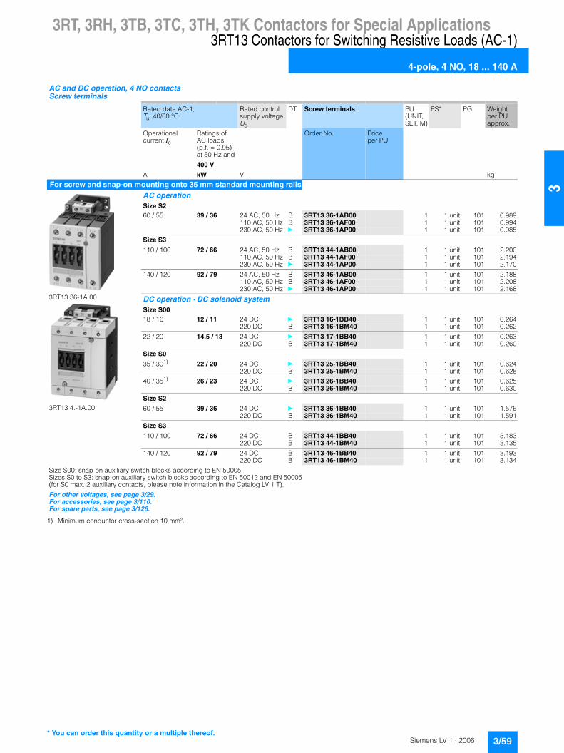
3RT, 3RH, 3TB, 3TC, 3TH, 3TK Contactors for Special Applications3RT13 Contactors for Switching Resistive Loads (AC-1)
4-pole, 4 NO, 18 ... 140 A
3/59Siemens LV 1 · 2006
3
1) Minimum conductor cross-section 10 mm².
AC and DC operation, 4 NO contacts Screw terminals
Rated data AC-1,Tu: 40/60 °C
Rated control supply voltage Us
DT Screw terminals PU (UNIT, SET, M)
PS* PG Weight per PU approx.
Operational current Ie
Ratings of AC loads(p.f. = 0.95)at 50 Hz and
Order No. Price per PU
400 V
A kW V kg
For screw and snap-on mounting onto 35 mm standard mounting rails
3RT13 36-1A.00
3RT13 4.-1A.00
AC operation Size S2 60 / 55 39 / 36 24 AC, 50 Hz B 3RT13 36-1AB00 1 1 unit 101 0.989
110 AC, 50 Hz B 3RT13 36-1AF00 1 1 unit 101 0.994230 AC, 50 Hz } 3RT13 36-1AP00 1 1 unit 101 0.985
Size S3
110 / 100 72 / 66 24 AC, 50 Hz B 3RT13 44-1AB00 1 1 unit 101 2.200110 AC, 50 Hz B 3RT13 44-1AF00 1 1 unit 101 2.194230 AC, 50 Hz } 3RT13 44-1AP00 1 1 unit 101 2.170
140 / 120 92 / 79 24 AC, 50 Hz B 3RT13 46-1AB00 1 1 unit 101 2.188110 AC, 50 Hz B 3RT13 46-1AF00 1 1 unit 101 2.208230 AC, 50 Hz } 3RT13 46-1AP00 1 1 unit 101 2.168
DC operation · DC solenoid system Size S00 18 / 16 12 / 11 24 DC } 3RT13 16-1BB40 1 1 unit 101 0.264
220 DC B 3RT13 16-1BM40 1 1 unit 101 0.262
22 / 20 14.5 / 13 24 DC } 3RT13 17-1BB40 1 1 unit 101 0.263220 DC B 3RT13 17-1BM40 1 1 unit 101 0.260
Size S0
35 / 301) 22 / 20 24 DC } 3RT13 25-1BB40 1 1 unit 101 0.624220 DC B 3RT13 25-1BM40 1 1 unit 101 0.628
40 / 351) 26 / 23 24 DC } 3RT13 26-1BB40 1 1 unit 101 0.625220 DC B 3RT13 26-1BM40 1 1 unit 101 0.630
Size S2
60 / 55 39 / 36 24 DC } 3RT13 36-1BB40 1 1 unit 101 1.576220 DC B 3RT13 36-1BM40 1 1 unit 101 1.591
Size S3
110 / 100 72 / 66 24 DC B 3RT13 44-1BB40 1 1 unit 101 3.183220 DC B 3RT13 44-1BM40 1 1 unit 101 3.135
140 / 120 92 / 79 24 DC B 3RT13 46-1BB40 1 1 unit 101 3.193220 DC B 3RT13 46-1BM40 1 1 unit 101 3.134
Size S00: snap-on auxiliary switch blocks according to EN 50005Sizes S0 to S3: snap-on auxiliary switch blocks according to EN 50012 and EN 50005(for S0 max. 2 auxiliary contacts, please note information in the Catalog LV 1 T).
For other voltages, see page 3/29.For accessories, see page 3/110.For spare parts, see page 3/126.
* You can order this quantity or a multiple thereof.

3RT, 3RH, 3TB, 3TC, 3TH, 3TK Contactors for Special Applications3RT13 Contactors for Switching Resistive Loads (AC-1)
4-pole, 4 NO, 18 ... 140 A
3/60 Siemens LV 1 · 2006
3
DC operation, 4 NO contacts Cage Clamp terminals
Rated data AC-1,Tu: 40/60 °C
Rated control supply voltage Us
DT Cage Clamp terminals PU (UNIT, SET, M)
PS* PG Weight per PU approx.
Operational current Ie
Ratings of AC loads(p.f. = 0.95) at 50 Hz and
Order No. Price per PU
400 V
A kW V kg
For screw and snap-on mounting onto 35 mm standard mounting rails
3RT13 1.-2B..0
DC operation · DC solenoid system Size S00 18 / 16 12 / 11 24 DC } 3RT13 16-2BB40 1 1 unit 101 0.260
220 DC B 3RT13 16-2BM40 1 1 unit 101 0.253
22 / 20 14.5 / 13 24 DC A 3RT13 17-2BB40 1 1 unit 101 0.260220 DC B 3RT13 17-2BM40 1 1 unit 101 0.254
Size S00: snap-on auxiliary switch blocks according to EN 50005
For other voltages, see page 3/29.For accessories, see page 3/110.For spare parts, see page 3/127.
* You can order this quantity or a multiple thereof.

3RT, 3RH, 3TB, 3TC, 3TH, 3TK Contactors for Special Applications3TK1 Contactors for Switching Resistive Loads (AC-1)
4-pole, 4 NO, 200 ... 1000 A
3/61Siemens LV 1 · 2006
3
■ Overview
EN 60947-4-1 (VDE 0660 Part 102)
The contactors also comply with the requirements of NFC 63–110 and NFC 20–040.
The contactors are suitable for use in any climate. They are finger-safe according to EN 50274. Terminal covers may have to be fitted onto the connecting bars, depending on the configuration with other devices.
Solenoids for 3TK10 to 3TK13 contactors: as withdrawable coils.
Surge suppression
Control circuit
Solenoids for 3TK1 contactors: can be retrofitted with RC elements.
■ Selection and ordering data
1) At 60 Hz: 240 V.
Screw terminals Screw mounting
3TK13
Rated data AC-1 Auxiliary contacts
Rated control supply voltage Us
DT Order No. Price per PU
PU (UNIT, SET, M)
PS* PG Weight per PU approx.
Operational current Ie up to 690 V(at 40 °C)
Ratings of AC loads (p.f. = 0.95) at
Version
230 V 400 V 690 V 1000 V
A kW kW kW kW NO NC V AC kg
AC operation200 75 130 225 205 2 2 220 ... 230, 50 Hz B 3TK10 42-0AP0 1 1 unit 101 4.423
230 ... 240, 50 Hz D 3TK10 42-0AU0 1 1 unit 101 4.449110/120, 50/60 Hz C 3TK10 42-0AF0 1 1 unit 101 4.37924, 50 Hz D 3TK10 42-0AB0 1 1 unit 101 4.432
250 90 165 280 200 2 2 220 ... 230, 50 Hz B 3TK11 42-0AP0 1 1 unit 101 4.746230 ... 240, 50 Hz D 3TK11 42-0AU0 1 1 unit 101 4.476110/120, 50/60 Hz D 3TK11 42-0AF0 1 1 unit 101 4.63424, 50 Hz D 3TK11 42-0AB0 1 1 unit 101 4.738
300 110 195 340 325 2 2 220 ... 230, 50 Hz B 3TK12 42-0AP0 1 1 unit 101 7.158230 ... 240, 50 Hz D 3TK12 42-0AU0 1 1 unit 101 7.167110/120, 50/60 Hz D 3TK12 42-0AF0 1 1 unit 101 7.12724, 50 Hz D 3TK12 42-0AB0 1 1 unit 101 7.129
350 130 230 395 370 2 2 220 ... 230, 50 Hz B 3TK13 42-0AP0 1 1 unit 101 7.156230 ... 240, 50 Hz D 3TK13 42-0AU0 1 1 unit 101 7.172110/120, 50/60 Hz D 3TK13 42-0AF0 1 1 unit 101 7.11824, 50 Hz D 3TK13 42-0AB0 1 1 unit 101 7.136
550 205 360 620 510 2 2 220 ... 230, 50 Hz1) B 3TK14 42-0AP0 1 1 unit 101 18.938230 ... 240, 50 Hz D 3TK14 42-0AU0 1 1 unit 101 19.041110/120, 50/60 Hz C 3TK14 42-0AF0 1 1 unit 101 19.094
800 300 525 905 575 2 2 220 ... 230, 50 Hz1) B 3TK15 42-0AP0 1 1 unit 101 19.068230 ... 240, 50 Hz D 3TK15 42-0AU0 1 1 unit 101 19.100110/120, 50/60 Hz C 3TK15 42-0AF0 1 1 unit 101 19.076
1000 375 655 1135 -- 2 2 220 ... 230, 50 Hz1) B 3TK17 42-0AP0 1 1 unit 101 20.030230 ... 240, 50 Hz D 3TK17 42-0AU0 1 1 unit 101 20.080110/120, 50/60 Hz D 3TK17 42-0AF0 1 1 unit 101 20.100
For accessories, see page 3/134 onwards.For spare parts, see page 3/142 onwards.
* You can order this quantity or a multiple thereof.

3RT, 3RH, 3TB, 3TC, 3TH, 3TK Contactors for Special Applications3TK20 Contactors
4-pole, 4 kW
3/62 Siemens LV 1 · 2006
3
■ Overview
AC and DC operation
IEC 60947 (VDE 0660).
The contactors are suitable for use in any climate.
The contactors with screw terminals are finger-safe according to EN 50274.
The contactors are available in versions with screw terminals, 6.3 mm plug connectors and solder pin connectors for soldering in printed circuit boards.
■ Application
The main area of application for the 3TK2 contactors with flat connectors is in household equipment. These contactors are also suitable for simple electric controllers. No auxiliary switch blocks can be retrofitted.
■ Selection and ordering data
Size 00 AC-1: operational current le = 16 A (at 55 °C)
1) Operating range at AC-1220 V: 0.85 to 1.15 x Us; lower operating range limit according to IEC 60947.
Rated dataUtilization categories AC-2 and AC-3
Main contacts DT Order No. Price per PU
PU (UNIT, SET, M)
PS* PG Weight per PU approx.
Operational current Ie
Ratings of induction motors at 50 Hz and
Version
at 400/380 V
230/ 220 V
400/ 380 V
500 V 690/ 660 V
A kW kW kW kW NO NC kgContactors with screw terminals � for screw and snap-on mounting onto 35 mm standard mounting rail
3TK20 ..-0...
AC operation9 2.4 4 4 4 4 -- B 3TK20 40-0AP0 1 1 unit 101 0.190
3 1 B 3TK20 31-0AP0 1 1 unit 101 0.1882 2 B 3TK20 22-0AP0 1 1 unit 101 0.188
DC operation · DC solenoid system9 2.4 4 4 4 4 -- B 3TK20 40-0BB4 1 1 unit 101 0.210
3 1 B 3TK20 31-0BB4 1 1 unit 101 0.2102 2 B 3TK20 22-0BB4 1 1 unit 101 0.209
Contactors with 6.3 mm x 0.8 mm flat connectors � for screw and snap-on mounting onto 35 mm standard mounting rail
3TK20 ..-3...
AC operation9 2.4 4 4 -- 4 -- C 3TK20 40-3AP0 1 1 unit 101 0.166
3 1 C 3TK20 31-3AP0 1 1 unit 101 0.1642 2 C 3TK20 22-3AP0 1 1 unit 101 0.180
DC operation · DC solenoid system9 2.4 4 4 -- 4 -- C 3TK20 40-3BB4 1 1 unit 101 0.185
3 1 C 3TK20 31-3BB4 1 1 unit 101 0.1872 2 C 3TK20 22-3BB4 1 1 unit 101 0.189
Contactors with 6.3 mm x 0.8 mm flat connectors � for screw mounting (diagonal)
3TK20 ..-7...
AC operation9 2.4 4 4 -- 4 -- B 3TK20 40-7AP0 1 1 unit 101 0.161
3 1 B 3TK20 31-7AP0 1 1 unit 101 0.1632 2 B 3TK20 22-7AP0 1 1 unit 101 0.162
DC operation · DC solenoid system9 2.4 4 4 -- 4 -- B 3TK20 40-7BB4 1 1 unit 101 0.183
3 1 B 3TK20 31-7BB4 1 1 unit 101 0.1872 2 B 3TK20 22-7BB4 1 1 unit 101 0.183
Contactors with solder pin connectors for printed circuit boards1) �for screw mounting (diagonal)
3TK20 ..-6...
AC operation9 2.4 4 4 -- 4 -- B 3TK20 40-6AP0 1 1 unit 101 0.159
3 1 B 3TK20 31-6AP0 1 1 unit 101 0.1602 2 B 3TK20 22-6AP0 1 1 unit 101 0.159
DC operation · DC solenoid system9 2.4 4 4 -- 4 -- B 3TK20 40-6BB4 1 1 unit 101 0.182
3 1 B 3TK20 31-6BB4 1 1 unit 101 0.1832 2 B 3TK20 22-6BB4 1 1 unit 101 0.181
For accessories, see page 3/137.
* You can order this quantity or a multiple thereof.
3RT, 3RH, 3TB, 3TC, 3TH, 3TK Contactors for Special Applications3TK20 Contactors
4-pole, 4 kW
3/63Siemens LV 1 · 2006
31) Operating range at 220 V: 0.85 to 1.15 x Us; lower operating range limit according to IEC 60947.
Please inquire about other voltages.
Contactor Type 3TK20
Rated control supply voltages(the 10th and 11th position of the order number must be changed)
AC operationCoils for AC 50 and 60 HzRated control supply voltage Us
Coils for AC 50 Hz50 Hz 60 Hz
V AC V AC
230/220 276 P01)
Contactor Type 3TK20
Rated control supply voltages(the 10th and 11th position of the order number must be changed)
DC operationRated control supply voltage Us
V DC
24 B4

3RT, 3RH, 3TB, 3TC, 3TH, 3TK Contactors for Special Applications3RT15 Contactors
4-pole, 2 NO + 2 NC, 4 ... 18.5 kW
3/64 Siemens LV 1 · 2006
3
■ Overview
AC and DC operation
EN 60947-4-1 (VDE 0660, Part 102)
The contactors are suitable for use in any climate. They are finger-safe according to EN 50274.
The accessories for the 3-pole SIRIUS contactors can also be used for the 4-pole versions.
■ Selection and ordering data
1) For switching poles; not suitable for reversing duty.
2) For size S00: coil operating rangeat 50 Hz: 0.8 ... 1.1 x Usat 60 Hz: 0.85 ... 1.1 x Us.
3) Required conductor cross-section: 10 mm².
AC and DC operation 2 NO contacts + 2 NC contacts1) Screw terminals
Rated data Rated control supply voltage Us
DT Screw terminals PU (UNIT, SET, M)
PS* PG Weight per PU approx.
AC-2 and AC-3,Tu: up to 60 °C
AC-1,Tu: 40/60 °C
Operational current Ie
Ratings of induction motors at 50 Hz and
Operational current Ie
Order No. Price per PU
400 V 400 V
A kW A V kg
For screw and snap-on mounting onto 35 mm standard mounting rails
3RT15 1.-1....
3RT15 26.-1 .
AC operation Size S002) 9 4 18 / 16 24 AC,
50/60 HzB 3RT15 16-1AB00 1 1 unit 101 0.205
110 AC, 50/60 Hz
B 3RT15 16-1AF00 1 1 unit 101 0.204
230 AC, 50/60 Hz
} 3RT15 16-1AP00 1 1 unit 101 0.202
12 5.5 22 / 20 24 AC, 50/60 Hz
A 3RT15 17-1AB00 1 1 unit 101 0.205
110 AC, 50/60 Hz
} 3RT15 17-1AF00 1 1 unit 101 0.203
230 AC, 50/60 Hz
} 3RT15 17-1AP00 1 1 unit 101 0.205
Size S0
25 11 40 / 353) 24 AC, 50 Hz
B 3RT15 26-1AB00 1 1 unit 101 0.395
110 AC, 50 Hz
} 3RT15 26-1AF00 1 1 unit 101 0.390
230 AC, 50 Hz
} 3RT15 26-1AP00 1 1 unit 101 0.393
Size S2
40 18.5 55 / 50 24 AC, 50 Hz
B 3RT15 35-1AB00 1 1 unit 101 0.983
110 AC, 50 Hz
B 3RT15 35-1AF00 1 1 unit 101 0.991
230 AC, 50 Hz
} 3RT15 35-1AP00 1 1 unit 101 0.984
DC operation · DC solenoid system Size S00 9 4 18 / 16 24 DC } 3RT15 16-1BB40 1 1 unit 101 0.263
220 DC B 3RT15 16-1BM40 1 1 unit 101 0.262
12 5.5 22 / 20 24 DC } 3RT15 17-1BB40 1 1 unit 101 0.265220 DC B 3RT15 17-1BM40 1 1 unit 101 0.259
Size S0
20 11 40 / 353) 24 DC } 3RT15 26-1BB40 1 1 unit 101 0.625220 DC B 3RT15 26-1BM40 1 1 unit 101 0.626
Size S2
40 18.5 55 / 50 24 DC } 3RT15 35-1BB40 1 1 unit 101 1.583220 DC B 3RT15 35-1BM40 1 1 unit 101 1.585
Size S00: snap-on auxiliary switch blocks according to EN 50005Sizes S0 to S3: snap-on auxiliary switch blocks according to EN 50012 and EN 50005(for S0 max. 2 auxiliary contacts, please note information in the Catalog LV 1 T ).
For other voltages, see page 3/29.For accessories, see page 3/110.For spare parts, see page 3/126.
* You can order this quantity or a multiple thereof.

3RT, 3RH, 3TB, 3TC, 3TH, 3TK Contactors for Special Applications3RT15 Contactors
4-pole, 2 NO + 2 NC, 4 ... 18.5 kW
3/65Siemens LV 1 · 2006
3
1) For switching poles; not suitable for reversing duty.
2) For size S00: coil operating rangeat 50 Hz: 0.8 ... 1.1 x Usat 60 Hz: 0.85 ... 1.1 x Us.
AC and DC operation 2 NO contacts + 2 NC contacts1) Cage Clamp terminals
Rated data Rated control supply voltage Us
DT Cage Clamp terminals PU (UNIT, SET, M)
PS* PG Weight per PU approx.
AC-2 and AC-3,Tu: up to 60 °C
AC-1,Tu: 40/60 °C
Operational current Ie
Ratings of induction motors at 50 Hz and
Operational current Ie
Order No. Price per PU
400 V 400 V
A kW A V kg
For screw and snap-on mounting onto 35 mm standard mounting rails
3RT15 1.-2....
AC operation Size S002) 9 4 18 / 16 24 AC,
50/60 HzB 3RT15 16-2AB00 1 1 unit 101 0.198
110 AC, 50/60 Hz
B 3RT15 16-2AF00 1 1 unit 101 0.196
230 AC, 50/60 Hz
} 3RT15 16-2AP00 1 1 unit 101 0.201
12 5.5 22 / 20 24 AC, 50/60 Hz
B 3RT15 17-2AB00 1 1 unit 101 0.200
110 AC, 50/60 Hz
B 3RT15 17-2AF00 1 1 unit 101 0.199
230 AC, 50/60 Hz
} 3RT15 17-2AP00 1 1 unit 101 0.201
DC operation · DC solenoid system Size S009 4 18 / 16 24 DC } 3RT15 16-2BB40 1 1 unit 101 0.260
220 DC B 3RT15 16-2BM40 1 1 unit 101 0.256
12 5.5 22 / 20 24 DC B 3RT15 17-2BB40 1 1 unit 101 0.262220 DC B 3RT15 17-2BM40 1 1 unit 101 0.255
For other voltages, see page 3/29.For accessories, see page 3/110.For spare parts, see page 3/127.
* You can order this quantity or a multiple thereof.

3RT, 3RH, 3TB, 3TC, 3TH, 3TK Contactors for Special Applications3RT16 Capacitor Contactors
12.5 ... 50 kvar
3/66 Siemens LV 1 · 2006
3
■ Overview
AC operation
IEC 60947, EN 60947 (VDE 0660)
The contactors are suitable for use in any climate. They are finger-safe according to EN 50274.
The 3RT16 capacitor switching contactors are special variants of the size S00 to S3 SIRIUS contactors. The capacitors are precharged by means of the mounted leading NO contacts and resistors; only then do the main contacts close.
This prevents disturbances in the power system and welding of the contactors.
Only discharged capacitors are permitted to be switched on with capacitor contactors.
The auxiliary switch block which is snapped onto the capacitor contactor contains the three leading NO contacts and in the case of S00 one standard NC contact (in addition to one NO contact in the basic unit) and in the case of S0 and S3 one standard NO contact, which is unassigned. Size S00 also contains another unassigned NO contact in the basic unit.
In addition, a 2-pole auxiliary contact block can be mounted laterally on the 3RT16 47 capacitor contactors (2 NO, 2 NC or 1 NO + 1 NC versions); type 3RH19 21-1EA.. . The fitting of auxiliary switches for 3RT16 17 and 3RT16 27 is not expandable.
For the capacitor making and switching capacity of the basic 3RT10 contactor variant, see Technical Specifications.
■ Selection and ordering data
1) For size S3: 55 °C.
2) Operating range: 0.85 ... 1.1 x Us.
3) For conductor cross-sections > 6 mm2
Use 3RV19 25-5AB terminals (2 units).
AC operationScrew terminals
3RT16 17-1A.03
3RT16 27-1A.01
3RT16 47-1A.01
Utilization category AC-6b Switching of AC capacitors for an ambient temperature of 60 °C1)
Auxiliary contacts, unas-signed
Rated control supply voltage Us
2)DT Screw terminals PU
(UNIT, SET, M)
PS* PG Weight per PU approx.
Capacitor rating at operating voltage 50/60 Hz
Order No. Price per PU
230 V 400 V 525 V 690 V
kvar kvar kvar kvar NO NC V AC Hz kg
For screw and snap-on mounting onto 35 mm standard mounting railsSize S00
3 … 7.5 5 … 12.5 7.5 … 15 10 … 21 1 1 24 50 / 60 } 3RT16 17-1AB03 1 1 unit 101 0.278110 B 3RT16 17-1AF03 1 1 unit 101 0.276230 } 3RT16 17-1AP03 1 1 unit 101 0.275
Size S03)
3.5 … 15 6 … 25 7.8 … 30 10 … 42 1 -- 24 50 B 3RT16 27-1AB01 1 1 unit 101 0.440110 B 3RT16 27-1AF01 1 1 unit 101 0.430230 } 3RT16 27-1AP01 1 1 unit 101 0.431
Size S3
3.5 … 30 5 … 50 7.5 … 60 10 … 84 1 -- 24 50 B 3RT16 47-1AB01 1 1 unit 101 2.037110 B 3RT16 47-1AF01 1 1 unit 101 2.040230 } 3RT16 47-1AP01 1 1 unit 101 2.033
For other voltages, see page 3/29.For accessories, see page 3/114.
* You can order this quantity or a multiple thereof.

3RT, 3RH, 3TB, 3TC, 3TH, 3TK Contactors for Special ApplicationsContactors with Extended Tolerance 0.7 ... 1.25 x , for Railway Applications
3RH11 contactor relays
3/67Siemens LV 1 · 2006
3
■ Overview
DC operation
IEC 60947-4-1, EN 60947-4-1 (VDE 0660, Part 102), for requirements according to IEC 60077-1 and IEC 60077-2.
The contactor relays are finger-safe according to EN 50274. The size S00 contactor relays have Cage Clamp connections for all terminals.
Ambient temperature
The permissible ambient temperature for operation of the contactor relays (across the full coil operating range) is -40 °C to +70 °C.
Uninterrupted duty at temperatures > +55 °C reduces the mechanical endurance, the current-carrying capacity of the conducting paths and the operating frequency.
■ Application
For operation in installations which are subject both to considerable variations in the control voltage and to high ambient temperatures, e.g. railway applications under extreme climatic conditions, rolling mills, etc.
Control and auxiliary circuits
The coils of the contactor relays have an extended tolerance from 0.7 to 1.25 x Us and are fitted as standard with varistors to provide protection against voltage surges. The opening delay is consequently 2 to 5 ms longer than for standard contactors.
3RH11..-0LA0
The DC solenoid systems of the contactor relays are modified (to hold-in coil) by means of a series resistor.
The size S00 contactor relays are supplied prewired with a plug-on module containing the series resistor. The varistor is integrated. A 4-pole auxiliary switch block (according to EN 50005) can be fitted additionally.
Mounting
At ambient temperatures up to 70 °C, the size S00 contactor relays are allowed to be mounted side by side.
3RH1122-2K.40
These contactor relays have an extended tolerance from 0.7 to 1.25 x Us; the coils are fitted with varistors as standard. An additional series resistor is not required. Please note:• Size S00: It is not possible to mount an auxiliary switch block.
At ambient temperatures > 60 °C � 70 °C, a clearance of 10 mm is required when they are mounted side by side.
■ Selection and ordering data
1) It is not possible to mount an auxiliary switch block. A clearance of 10 mm is required for side-by-side mounting at ambient temperatures > 60 °C.
2) Version without series resistor.
3) One 4-pole auxiliary switch block according to EN 50005 can be mounted; no clearance required up to 70 °C.
DC operation · DC solenoid system Cage Clamp terminals For screw and snap-on mounting onto standard mounting rail Solenoid fitted with varistor
3RH11 22-2K.40: 3RH11 22-2K.40-0LA0
Rated operational currentIe/AC-15/AC-14Tu: 70 °C at
Contacts Rated control supply voltage Us
DT Cage Clamp terminals PU (UNIT, SET, M)
PS* PG Weight per PU approx.
Version Order No. Price per PU230 V 400 V 500 V 690 V
A A A A NO NC V DC kg
3RH11 contactor relaysSize S00 Cage Clamp terminals for all connections6 3 2 1 2 21) 24 2)
} 3RH11 22-2KB40 1 1 unit 101 0.255110 2) A 3RH11 22-2KF40 1 1 unit 101 0.256
6 3 2 1 2 13) 24 A 3RH11 22-2KB40-0LA0 1 1 unit 101 0.284110 A 3RH11 22-2KF40-0LA0 1 1 unit 101 0.285
Us
* You can order this quantity or a multiple thereof.

3RT, 3RH, 3TB, 3TC, 3TH, 3TK Contactors for Special ApplicationsContactors with Extended Tolerance 0.7 ... 1.25 x , for Railway Applications
3TH4 contactor relays
3/68 Siemens LV 1 · 2006
3
■ Overview
3TH4 contactor relays
EN 60947-4-1.
For requirements according to IEC 60077-1 and IEC 60077-2.
The contactors are finger-safe according to EN 50274. Terminal covers may have to be fitted onto the connecting bars, depending on the configuration with other devices.
■ Application
For operation in plants which are subject both to considerable variations in the control voltage and to high ambient temperatures, e.g. in railway applications.
■ Selection and ordering data
1) Contacts not extendable.
With screw terminalsFor screw and snap-on mounting onto 35 mm standard mounting rail Solenoid fitted with varistor
3TH4
Contacts Rated operational current Ie/AC-15/AC-14
Contacts1) Rated control supply voltage Us
DT Order No. Price per PU
PU (UNIT, SET, M)
PS* PG Weight per PU approx.
Ident. No. acc. to EN 50011
230 V 400 V 500 V 690 V
Number A A A A NO NC V kg
3TH42 contactor relays � DC operation � DC solenoid system8 10 6 4 2 44 E 4 4 24 DC B 3TH42 44-0LB4 1 1 unit 101 0.674
110 DC B 3TH42 44-0LF4 1 1 unit 101 0.661
53 E 5 3 24 DC C 3TH42 53-0LB4 1 1 unit 101 0.669110 DC C 3TH42 53-0LF4 1 1 unit 101 0.660
62 E 6 2 24 DC B 3TH42 62-0LB4 1 1 unit 101 0.667110 DC B 3TH42 62-0LF4 1 1 unit 101 0.663
For accessories, see page 3/139.
Us
* You can order this quantity or a multiple thereof.

3RT, 3RH, 3TB, 3TC, 3TH, 3TK Contactors for Special ApplicationsContactors with Extended Tolerance 0.7 ... 1.25 x , for Railway Applications
3RT10 motor contactors, 5.5 ... 45 kW
3/69Siemens LV 1 · 2006
3
■ Overview
DC operation
IEC 60947-4-1, EN 60947-4-1 (VDE 0660, Part 102), for requirements according to IEC 60077-1 and IEC 60077-2.
The contactors are finger-safe according to EN 50274 (excep-tion: series resistors S0 to S3). The contactors are available with both Cage Clamp and screw terminals. The size S00 contactors have Cage Clamp terminals for all connections. The auxiliary conductor and coil terminals of sizes S0 to S3 are all Cage Clamp terminals.
Ambient temperature
The permissible ambient temperature for operation of the contactors (across the full coil operating range) is -40 °C to +70 °C.
Uninterrupted duty at temperatures > +55 °C reduces the mechanical endurance, the current-carrying capacity of the conducting paths and the operating frequency.
Dimensions
Attaching resistors increases the width of contactor sizes S0 to S3 (see Dimensional Drawings).
■ Application
For operation in installations which are subject both to consider-able variations in the control voltage and to high ambient tem-peratures, e.g. railway applications under extreme climatic con-ditions, rolling mills, etc.
Control and auxiliary circuits
The coils of the contactors have an extended tolerance from 0.7 to 1.25 x Us and are fitted as standard with varistors to provide protection against voltage surges. The opening delay is consequently 2 to 5 ms longer than for standard contactors.
3RT10 ..-0LA0
The DC solenoid systems of the contactors are modified (to hold-in coil) by means of a series resistor.
The size S00 contactors are supplied prewired with a plug-on module containing the series resistor. The varistor is integrated. A 4-pole auxiliary switch block (according to EN 50005) can be fitted additionally.
The size S0 to S3 contactors are equipped on the front with an auxiliary switch block with 2 NO + 2 NC contacts. The separate series resistor, which is attached laterally next to the contactor on the 35 mm standard mounting rail, is fitted with connecting leads for mounting the contactors. A circuit diagram showing the terminals is stuck onto each contactor. One NC of the auxiliary contacts is required for the series resistor function. The selection and ordering data shows the number of additional, unassigned auxiliary contacts. It is only possible to extend the number of auxiliary contacts with size S00.
Mounting
At ambient temperatures up to 70 °C, the size S00 contactors and contactor relays are allowed to be mounted side by side. The resistor module of the size S0 to S3 contactors must be mounted to the left of the contactor owing to the prefabricated connecting leads.
3RT10 17-2K.4., 3RT10 2.-3K.40
These contactors have an extended tolerance from 0.7 to 1.25 x Us; the coils are fitted with varistors as standard. An additional series resistor is not required.Please note:• Size S00: it is not possible to mount an auxiliary switch block.• Size S0: up to two single-pole auxiliary switch blocks can be
mounted.
At ambient temperatures > 60 °C � 70 °C, a clearance of 10 mm is required when they are mounted side by side.
3RT10 contactors with contactor control unit, extended tolerance
Control and auxiliary circuits
The coils of the contactors have an extended tolerance from 0.7 to 1.25 x Us and are fitted as standard with varistors to provide protection against voltage surges. The opening delay is consequently 2 ms to 5 ms longer than for standard contactors.
3RT10 ..-.X.40-0LA2
The contactors are energized using series-connected control electronics, ensuring the coil operating range of 0.7 to 1.25 x Us at an ambient temperature of 70 °C. They are supplied as complete self-contained units with a built-on contactor control unit. A varistor is integrated for damping opening surges in the coil.
The possibility of mounting auxiliary switches is the same as that for equivalent standard contactors.
Mounting
At ambient temperatures up to 70 °C, sizes S0 to S3 of these contactor versions are allowed to be mounted side by side.
Ambient temperature
The permissible ambient temperature for operation of the contactors (across the full operating range of the coils) is -40 °C to +70 °C.Uninterrupted duty at temperatures > +55 °C reduces the mechanical endurance, the current-carrying capacity of the conducting paths and the operating frequency.
Dimensions
Because of the built-on contactor control unit, the height of the size S0 to S3 contactors increases by up to 34 mm (see Dimensional Drawings).
Us

3RT, 3RH, 3TB, 3TC, 3TH, 3TK Contactors for Special ApplicationsContactors with Extended Tolerance 0.7 ... 1.25 x , for Railway Applications
3RT10 motor contactors, 5.5 ... 45 kW
3/70 Siemens LV 1 · 2006
3
■ Selection and ordering data
1) It is not possible to mount an auxiliary switch block. A clearance of 10 mm is required for side-by-side mounting at ambient temperatures >60 °C.
2) One 4-pole auxiliary switch block according to EN 50005 can be mounted; no clearance required up to 70 °C.
3) Version without series resistor.
4) Up to two single-pole auxiliary switch blocks can be mounted. A clearance of 10 mm is required for side-by-side mounting at ambient temperatures >60 °C.
5) The number of auxiliary contacts cannot be increased; no clearance required up to 70 °C.
DC operation · DC solenoid system Cage Clamp terminalsFor screw and snap-on mounting onto standard mounting rail Solenoid fitted with varistor
3RT10 17-2K.4.-0LA0 3RT10 2.-3K.40
3RT10 3.-3K.44-0LA0
Rated dataAC-2 and AC-3Tu: 70 °C
Auxiliary contacts Rated control supply voltage Us
DT Cage Clamp terminals PU (UNIT, SET, M)
PS* PG Weight per PU approx.
Operational current Ie at
Rating ofinduction motors at
Version Order No. Price per PU
400 V 230 V 400 V 500 V 690 V
A kW kW kW kW NO NC V DC kg
3RT10 contactors for switching motorsSize S00 Cage Clamp terminals for all connections12 3 5.5 5.5 5.5 11) -- 243)
} 3RT10 17-2KB41 1 1 unit 101 0.2561103) B 3RT10 17-2KF41 1 1 unit 101 0.256
12 3 5.5 5.5 5.5 -- 11) 243)} 3RT10 17-2KB42 1 1 unit 101 0.256
1103) B 3RT10 17-2KF42 1 1 unit 101 0.255
12 3 5.5 5.5 5.5 -- 12) 24 A 3RT10 17-2KB42-0LA0 1 1 unit 101 0.283110 B 3RT10 17-2KF42-0LA0 1 1 unit 101 0.285
Size S0 Cage Clamp terminals for coil connections and auxiliary contacts17 4 7.5 10 11 -- --4) 243)
} 3RT10 25-3KB40 1 1 unit 101 0.5801103) B 3RT10 25-3KF40 1 1 unit 101 0.574
25 5.5 11 11 11 -- --4) 243)} 3RT10 26-3KB40 1 1 unit 101 0.581
1103) B 3RT10 26-3KF40 1 1 unit 101 0.575
17 4 7.5 10 11 2 25) 24 B 3RT10 25-3KB44-0LA0 1 1 unit 101 0.760110 B 3RT10 25-3KF44-0LA0 1 1 unit 101 0.745
25 5.5 11 11 11 2 25) 24 B 3RT10 26-3KB44-0LA0 1 1 unit 101 0.758110 B 3RT10 26-3KF44-0LA0 1 1 unit 101 0.742
Size S2 Cage Clamp terminals for coil connections and auxiliary contacts32 7.5 15 18.5 18.5 2 25) 24 B 3RT10 34-3KB44-0LA0 1 1 unit 101 1.630
110 B 3RT10 34-3KF44-0LA0 1 1 unit 101 1.664
40 11 18.5 22 22 2 25) 24 B 3RT10 35-3KB44-0LA0 1 1 unit 101 1.648110 B 3RT10 35-3KF44-0LA0 1 1 unit 101 1.656
50 15 22 30 22 2 25) 24 B 3RT10 36-3KB44-0LA0 1 1 unit 101 1.647110 B 3RT10 36-3KF44-0LA0 1 1 unit 101 1.669
Size S3 Cage Clamp terminals for coil connections and auxiliary contacts65 18.5 30 37 43 2 25) 24 B 3RT10 44-3KB44-0LA0 1 1 unit 101 3.070
110 B 3RT10 44-3KF44-0LA0 1 1 unit 101 3.028
80 22 37 45 55 2 25) 24 B 3RT10 45-3KB44-0LA0 1 1 unit 101 3.085110 B 3RT10 45-3KF44-0LA0 1 1 unit 101 2.670
95 22 45 55 55 2 25) 24 B 3RT10 46-3KB44-0LA0 1 1 unit 101 3.090110 B 3RT10 46-3KF44-0LA0 1 1 unit 101 3.042
For spare parts, see page 3/127.
Us
* You can order this quantity or a multiple thereof.