controls plc based controllers: pcd1 · integral saia®s-bus, ... (pgu) or rs 232 serial data port...
TRANSCRIPT

Controls
Smar
t so
luti
ons
for
com
fort
an
d sa
fety
Edition 26/350 E1
PLC based controllers: PCD1 Modular in function, compact in form
Powerful functions – already integrated in base unit■ Up to 64/2048 inputs/outputs Modular structure with 4 sockets for digital, analo gue, counting, measuring
and/or motion control modules– up to 64 central inputs/outputs– up to 2048 local inputs/outputs (e. g. PROFIBUS DP)
■ Up to 140 KBytes user memory for programs, text and data blocks.
■ Up to 2 serial data ports can be fitted with a choice of RS 232, RS 422, RS 485 or TTY/current loop 20 mA.
■ Field bus connections can be fitted with a choice of PROFIBUS DP as master or slave, LONWORKS® or Ethernet-TCP/IP.
■ Standard inputs: Fast counters and interrupt inputs directly on CPU of con-troller.
High performance operating system and efficient programming tools■ Efficient programming with PG5 due to its many programming languages, such
as IL, FUPLA, GRAFTEC etc. and its diagnostic and other add-on tools. An efficient instruction set, comprehensive FBox libraries and a structure that com plies with IEC 1131-3 simplify the editing of transpa rent programs.
■ Portability of user programs due to harmonized system re sources and the integral SAIA®S-Bus, user programs are transferable across the entire PCD family (PCD1 up to PCD6) and capable of running.
■ Short reaction times due to direct accessing of I/O signals, without the passing through a process map (image).
■ Flexible network integration due to through communications and program-ming via Ethernet-TCP/IP to the connec ted field bus stations (PROFIBUS DP/FMS or LONWORKS®).
PCD1
2
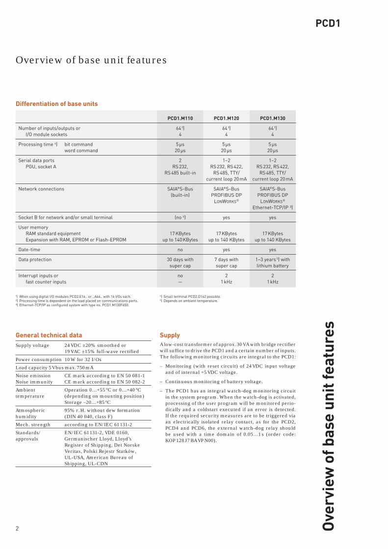
General technical dataSupply voltage 24 VDC ±20% smoothed or 19 VAC ±15% full-wave rectified
Power consumption 10 W for 32 I/Os
Load capacity 5 V bus max. 750 mA
Noise emission CE mark according to EN 50 081-1Noise immunity CE mark according to EN 50 082-2
Ambient Operation 0…+55 °C or 0…+40 °C temperature (depending on mounting position) Storage –20…+85 °C
Atmospheric 95% r. H. without dew formation humidity (DIN 40 040, class F)
Mech. strength according to EN/IEC 61 131-2
Standards/ EN/IEC 61 131-2, VDE 0160, approvals Germanischer Lloyd, Lloyd’s Register of Shipping, Det Norske Veritas, Polski Rejestr Statków, UL-USA, American Bureau of Shipping, UL-CDN
SupplyA low-cost transformer of approx. 30 VA with bridge rectifier will suffice to drive the PCD1 and a certain number of inputs. The following monitoring circuits are integral to the PCD1:
– Monitoring (with reset circuit) of 24 VDC input voltage and of internal +5 VDC voltage.
– Continuous monitoring of battery voltage.
– The PCD1 has an integral watch-dog monitoring circuit in the system program. When the watch-dog is activated, processing of the user program will be monitored perio-dically and a coldstart executed if an error is detected. If the required security measures are to be triggered via an electrically isolated relay contact, as for the PCD2, PCD4 and PCD6, the external watch-dog relay should be used with a time domain of 0.05…1 s (order code: KOP 128 J7 BA VP N00).
Differentiation of base units
¹) When using digital I/O modules PCD2.E16.. or ..A46.. with 16 I/Os each.²) Processing time is dependent on the load placed on communications ports.³) Ethernet-TCP/IP as configured system with type no. PCD1.M130F650.
4) Small terminal PCD2.D162 possible. 5) Depends on ambient temperature.
PCD1.M110
64 ¹)4
5 µs20 µs
2RS 232,
RS 485 built-in
SAIA®S-Bus(built-in)
(no 4)
17 KBytesup to 140 KBytes
no
30 days withsuper cap
no—
PCD1.M120
64 ¹)4
5 µs20 µs
1–2RS 232, RS 422,
RS 485, TTY/current loop 20 mA
SAIA®S-BusPROFIBUS DP
LONWORKS®
yes
17 KBytesup to 140 KBytes
yes
7 days withsuper cap
21 kHz
PCD1.M130
64 ¹)4
5 µs20 µs
1–2RS 232, RS 422,
RS 485, TTY/current loop 20 mA
SAIA®S-BusPROFIBUS DP
LONWORKS®
Ethernet-TCP/IP ³)
yes
17 KBytesup to 140 KBytes
yes
1–3 years 5) withlithium battery
21 kHz
Overview of base unit features
Ove
rvie
w o
f bas
e un
it fe
atur
es
Number of inputs/outputs or I/O module sockets
Processing time 4) bit command word command
Serial data ports PGU, socket A
Network connections
Socket B for network and/or small terminal
User memory RAM standard equipment Expansion with RAM, EPROM or Flash-EPROM
Date-time
Data protection
Interrupt inputs or fast counter inputs

PCD1
B
A
Field bus connections Socket B
PROFIBUS DP: For this network two modules are available as master or slave.
LONWORKS®: These modules form the platform for vendor-indepen-dent communications.
Pages 6/7
Small terminal for direct mounting Socket B
also with additional connection for LONWORKS® or PROFIBUS DP.
Page 11
Counting, measuring, motion control modules Pages 8/9
Serial data port Socket A
1 serial data port as RS 422/RS 485, RS 485 electrically isolated, RS 232 for modem or TTY/current loop 20 mA
Pages 6/7
User memory17 KBytes RAM and up to 128 KBytes as add-on RAM, EPROM or Flash-EPROM chip for increasing the memory capacity
Page 5
Digital or analogue modem moduleCan be inserted on I/O module sockets
Page 6
Digital and analogue input/output modules Pages 10/11
Ethernet-TCP/IP Socket B (only PCD1.M130)
Intelligent co-processor module with fast dual-port RAM interface to the CPU, Ethernet 10 Base-T/ 100 Base-TX. SAIA®S-Bus with UDP/IP for PG5⇔PCD commu-nication and PCD®PCD multi-master communication. Trans mission and receipt of TCP and UDP data packages for communication with any choice of system.
Page 6
SAIA®S-Bus (RS 485)The efficient protocol for this master-slave network is supported by every PCD both as master and as slave. Economical design across a serial RS 485 data port, without additional module.
Pages 6/7
The adaptive controller platform
Syst
em o
verv
iew
: Har
dwar
e

PCD1
4
Block diagram of resources, using PCD1.M130 as example
SUPPLY I/O MODULESADDR 0…63
CPU and I/O BUS
DATE-TIMEnvol
CPU
..F.. MODULE COMMUNI -
CATIONS DISPLAY
RUN/HALT
INTERRUPT INPUTS
..F.. MODULE COMMUNI -CATIONS
SERIAL DATA PORT/FIELD BUS/ETHERNET-TCP/IP
FAST COUNTERS
PGU ¹)RS 232
USER MEMORY
USER MEDIA
R register T timer C counter F flag vol volatile nvol non volatile
¹) PGU: Connection for programming unit
MEMORYMAP
EEPROM
DB
TX
P
Tvol
Cnvol
Rnvol
Fvol
Fnvol
P program TX text DB data block
µCWATCH DOG
Identical system resources for the entire PCD familyRegisters 4096 × 32 bit, non-volatile
Computational Integers: –2 147 483 648… ranges +2 147 483 647 (–231…+231–1) Floating-point numbers: ±9.22337 × 10¹⁸…±5.42101 × 10⁻²⁰
Formats: decimal, binary, BCD, hexadecimal or floating point
Index registers 17 × 13 bit (1 each per COB and XOB)
Timers/counters 1600 volatile timers or non-volatile counters, division programmable
Counting range: 31 bit, unsigned (0…2 147 483 647)
Timing range: 31 bit, unsigned (0…2 147 483 647 timing signals, selectable from 10 ms up to 10 s)
Flags 8192 × 1 bit, volatile or non-volatile, division programmable
Date-time Time values: s/min/h, week/day of week, month/day of month, year Accuracy: better than 15 s/month Power reserve: 1 to 3 years
Diverse system resources
Syst
em r
esou
rces
PCD1
5
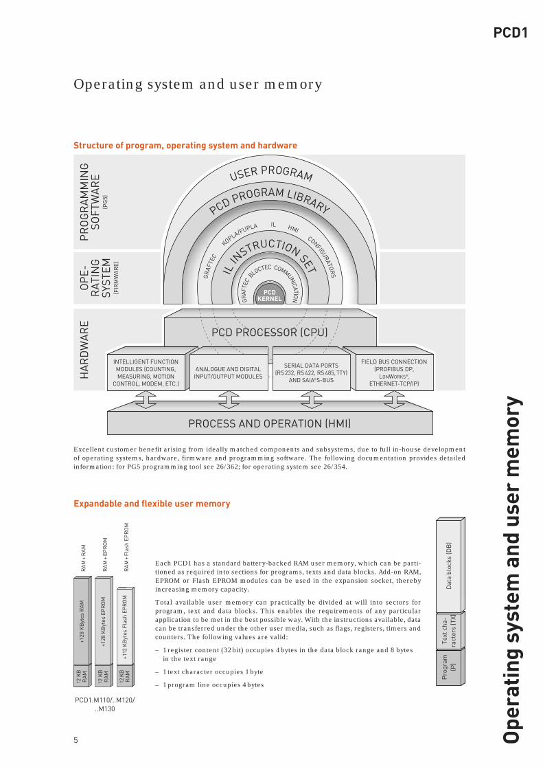
Expandable and flexible user memory
+128
KB
ytes
RA
MR
AM
+ R
AM
+128
KB
ytes
EP
RO
MR
AM
+ E
PR
OM
+112
KB
ytes
Fla
sh E
PR
OM
RA
M +
Fla
sh E
PR
OM
12 K
BR
AM
12 K
BR
AM
12 K
BR
AM
Each PCD1 has a standard battery-backed RAM user memory, which can be parti-tioned as required into sections for programs, texts and data blocks. Add-on RAM, EPROM or Flash EPROM modules can be used in the expansion socket, thereby increasing memory capacity.
Total available user memory can practically be divided at will into sectors for program, text and data blocks. This enables the requirements of any particular application to be met in the best possible way. With the instructions available, data can be transferred under the other user media, such as flags, registers, timers and counters. The following values are valid:
– 1 register content (32 bit) occupies 4 bytes in the data block range and 8 bytes in the text range
– 1 text character occupies 1 byte
– 1 program line occupies 4 bytes
Structure of program, operating system and hardware
Excellent customer benefit arising from ideally matched components and subsystems, due to full in-house development of operating systems, hardware, firmware and programming software. The following documentation provides detailed information: for PG5 programming tool see 26/362; for operating system see 26/354.
PCD1.M110/..M120/..M130
Dat
a bl
ocks
(DB
)Te
xt c
ha-
ract
ers
(TX)
Pro
gram
(P
)
USER PROGRAM
PCD PROGRAM LIBRARYG
RAF
TEC
K
OPLA/FUPLA IL HMI CONFIGURATOR
SIL IN
STRUCTION SETGR
AFTE
C BLOCTEC COMMUNICATION
PCDKERNEL
PCD PROCESSOR (CPU)
INTELLIGENT FUNCTION MODULES (COUNTING, MEASURING, MOTION
CONTROL, MODEM, ETC.)
ANALOGUE AND DIGITAL INPUT/OUTPUT MODULES
SERIAL DATA PORTS (RS 232, RS 422, RS 485, TTY)
AND SAIA®S-BUS
FIELD BUS CONNECTION (PROFIBUS DP,
LONWORKS®, ETHERNET-TCP/IP)
PROCESS AND OPERATION (HMI)
HA
RD
WA
RE
OP
E-R
ATI
NG
SY
STEM
(FIR
MW
ARE)
PR
OG
RA
MM
ING
SOFT
WA
RE
(PG
5)
Operating system and user memory
Ope
ratin
g sy
stem
and
use
r m
emor
y
PCD1
B
A
6
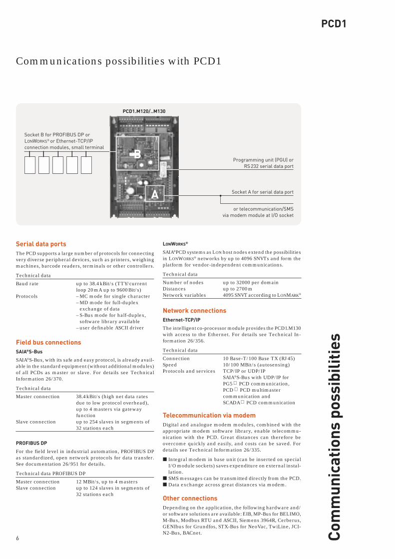
Socket B for PROFIBUS DP or LONWORKS® or Ethernet-TCP/IP connection modules, small terminal
Socket A for serial data port
or telecommunication/SMS via modem module at I/O socket
Programming unit (PGU) or RS 232 serial data port
Serial data portsThe PCD supports a large number of protocols for connecting very diverse peripheral devices, such as printers, weighing machines, barcode readers, terminals or other controllers.
Technical data
Baud rate up to 38.4 kBit/s (TTY/current loop 20 mA up to 9600 Bit/s)Protocols – MC mode for single character – MD mode for full-duplex exchange of data – S-Bus mode for half-duplex, software library available – user definable ASCII driver
Field bus connectionsSAIA®S-Bus
SAIA®S-Bus, with its safe and easy protocol, is already avail-able in the standard equipment (without additional modules) of all PCDs as master or slave. For details see Technical Information 26/370.
Technical data
Master connection 38.4 kBit/s (high net data rates due to low protocol overhead), up to 4 masters via gateway functionSlave connection up to 254 slaves in segments of 32 stations each
PROFIBUS DP
For the field level in industrial automation, PROFIBUS DP as standardized, open network protocols for data transfer. See documentation 26/951 for details.
Technical data PROFIBUS DP
Master connection 12 MBit/s, up to 4 masters Slave connection up to 124 slaves in segments of 32 stations each
LONWORKS®
SAIA®PCD systems as LON host nodes extend the possibilities in LONWORKS® networks by up to 4096 SNVTs and form the platform for vendor-independent communications.
Technical data
Number of nodes up to 32000 per domainDistances up to 2700 mNetwork variables 4095 SNVT according to LONMARK®
Network connectionsEthernet-TCP/IP
The intelligent co-processor module provides the PCD1.M130 with access to the Ethernet. For details see Technical In-formation 26/356.
Technical data
Connection 10 Base-T/100 Base TX (RJ 45)Speed 10/100 MBit/s (autosensing)Protocols and services TCP/IP or UDP/IP SAIA®S-Bus with UDP/IP for PG5 ⇔ PCD communication, PCD ⇔ PCD multimaster communication and SCADA ⇔ PCD communication
Telecommunication via modemDigital and analogue modem modules, combined with the appropriate modem software library, enable telecommu-nication with the PCD. Great distances can therefore be overcome quickly and easily, and costs can be saved. For details see Technical Information 26/335.
■ Integral modem in base unit (can be inserted on special I/O module sockets) saves expenditure on external instal-lation.
■ SMS messages can be transmitted directly from the PCD.■ Data exchange across great distances via modem.
Other connectionsDepending on the application, the following hardware and/or software solutions are available: EIB, MP-Bus for BELIMO, M-Bus, Modbus RTU and ASCII, Siemens 3964R, Cerberus, GENIbus for Grundfos, STX-Bus for NeoVac, TwiLine, JCI-N2-Bus, BACnet.
PCD1.M120/..M130
Com
mun
icat
ions
pos
sibi
litie
s
Communications possibilities with PCD1
PCD1
7
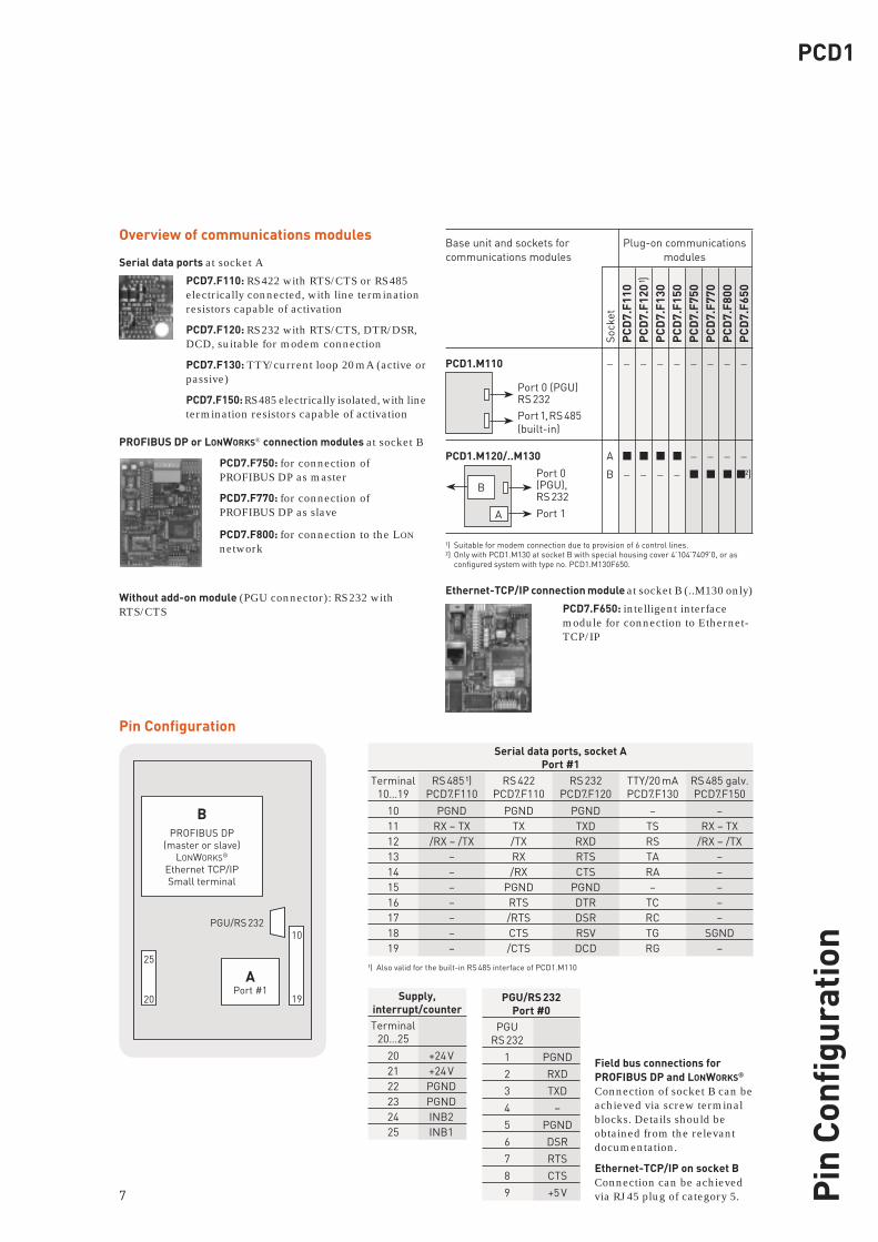
Overview of communications modules
Serial data ports at socket A
PCD7.F110: RS 422 with RTS/CTS or RS 485 electrically connected, with line termination resistors capable of activation
PCD7.F120: RS 232 with RTS/CTS, DTR/DSR, DCD, suitable for modem connection
PCD7.F130: TTY/current loop 20 mA (active or passive)
PCD7.F150: RS 485 electrically isolated, with line termination resistors capable of activation
PROFIBUS DP or LONWORKS® connection modules at socket B
PCD7.F750: for connection of PROFIBUS DP as master
PCD7.F770: for connection of PROFIBUS DP as slave
PCD7.F800: for connection to the LON network
Without add-on module (PGU connector): RS 232 with RTS/CTS
BPROFIBUS DP
(master or slave)LONWORKS®
Ethernet TCP/IPSmall terminal
APort #1
25
20
10
19
PGU/RS 232
Pin Configuration
PGU/RS 232Port #0
PGU RS 232
1 PGND
2 RXD
3 TXD
4 –
5 PGND
6 DSR
7 RTS
8 CTS
9 +5 V
Field bus connections for PROFIBUS DP and LONWORKS® Connection of socket B can be achieved via screw terminal blocks. Details should be obtained from the relevant documentation.
Ethernet-TCP/IP on socket BConnection can be achieved via RJ 45 plug of category 5.
Serial data ports, socket APort #1
Terminal RS 485 ¹) RS 422 RS 232 TTY/20 mA RS 485 galv. 10…19 PCD7.F110 PCD7.F110 PCD7.F120 PCD7.F130 PCD7.F150
10 PGND PGND PGND – – 11 RX – TX TX TXD TS RX – TX 12 /RX – /TX /TX RXD RS /RX – /TX 13 – RX RTS TA – 14 – /RX CTS RA – 15 – PGND PGND – – 16 – RTS DTR TC – 17 – /RTS DSR RC – 18 – CTS RSV TG SGND 19 – /CTS DCD RG –
Supply,interrupt/counter
Terminal 20…25
20 +24 V 21 +24 V 22 PGND 23 PGND 24 INB2 25 INB1
¹) Also valid for the built-in RS 485 interface of PCD1.M110
Pin
Con
figur
atio
n
Sock
etP
CD
7.F1
10P
CD
7.F1
20 ¹)
PC
D7.
F130
PC
D7.
F150
PC
D7.
F750
PC
D7.
F770
PC
D7.
F800
PC
D7.
F650
Port 0(PGU),RS 232Port 1
B
A
Port 0 (PGU)RS 232Port 1, RS 485 (built-in)
Ethernet-TCP/IP connection module at socket B (..M130 only)
PCD7.F650: intelligent interface module for connection to Ethernet-TCP/IP
Base unit and sockets for Plug-on communications communications modules modules
PCD1.M110 – – – – – – – – –
PCD1.M120/..M130 A ■ ■ ■ ■ – – – –
B – – – – ■ ■ ■ ■ ²)
¹) Suitable for modem connection due to provision of 6 control lines. ²) Only with PCD1.M130 at socket B with special housing cover 4’104’7409’0, or as
configured system with type no. PCD1.M130F650.
B
AM M M
M M M
M M M
8
PCD1.M120/..M130
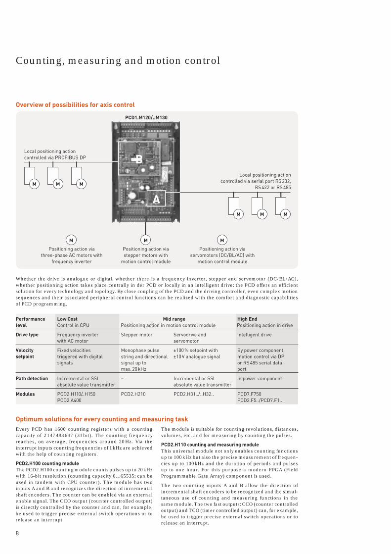
Whether the drive is analogue or digital, whether there is a frequency inverter, stepper and servomotor (DC/BL/AC), whether positioning action takes place centrally in der PCD or locally in an intelligent drive: the PCD offers an efficient solution for every technology and topology. By close coupling of the PCD and the driving controller, even complex motion sequences and their associated peripheral control functions can be realized with the comfort and diagnostic capabilities of PCD programming.
Local positioning action controlled via PROFIBUS DP
Local positioning action controlled via serial port RS 232,
RS 422 or RS 485
Positioning action via three-phase AC motors with
frequency inverter
Positioning action via stepper motors with
motion control module
Positioning action via servomotors (DC/BL/AC) with
motion control module
Every PCD has 1600 counting registers with a counting capa city of 2 147 483 647 (31 bit). The counting frequency reaches, on average, frequencies around 20 Hz. Via the interrupt inputs counting frequencies of 1 kHz are achieved with the help of counting registers.
PCD2.H100 counting moduleThe PCD2.H100 counting module counts pulses up to 20 kHz with 16-bit resolution (counting capacity 0…65535; can be used in tandem with CPU counter). The module has two inputs A and B and recognizes the direction of incremental shaft encoders. The counter can be enabled via an external enable signal. The CCO output (counter controlled output) is directly controlled by the counter and can, for example, be used to trigger precise external switch operations or to release an interrupt.
The module is suitable for counting revolutions, distances, volumes, etc. and for measuring by counting the pulses.
PCD2.H110 counting and measuring moduleThis universal module not only enables counting functions up to 100 kHz but also the precise measurement of frequen-cies up to 100 kHz and the duration of periods and pulses up to one hour. For this purpose a modern FPGA (Field Programmable Gate Array) component is used.
The two counting inputs A and B allow the direction of incremental shaft encoders to be recognized and the simul-taneous use of counting and measuring functions in the same module. The two fast outputs: CCO (counter controlled output) and TCO (timer controlled output) can, for example, be used to trigger precise external switch operations or to release an interrupt.
Optimum solutions for every counting and measuring task
Performance Low Cost Mid range High Endlevel Control in CPU Positioning action in motion control module Positioning action in drive
Drive type Frequency inverter Stepper motor Servodrive and Intelligent drive with AC motor servomotor
Velocity Fixed velocities Monophase pulse ±100 % setpoint with By power component, setpoint triggered with digital string and directional ±10 V analogue signal motion control via DP signals signal up to or RS 485 serial data max. 20 kHz port
Path detection Incremental or SSI – Incremental or SSI In power component absolute value transmitter absolute value transmitter
Modules PCD2.H110/..H150 PCD2.H210 PCD2.H31../..H32.. PCD7.F750 PCD2.A400 PCD2.F5../PCD7.F1..
Overview of possibilities for axis control
Counting, measuring and motion control

PCD1
9
Commissioning tool for motion control modulesThe software package can run as a stand-alone program or be integrated into the PG5. It is capable of running under Windows 98, 2000 and NT and offers the following perfor-mance features:
■ Support for the commissioning, configuration and pro-gramming of motion control modules.
■ Direct, easy access to all standard ..H.. module functions.
■ Movement of axis and adjustment of control parameters without writing a line of program code.
■ Entry, testing and storage of motion parameters.
■ Tracing and graphical representation of motion sequences and PCD data.
Overview of modules for axis control
Module Velocity profile Drive Frequency Output Count range/ Number Current Encoder position distance of axes draw ¹)
PCD2.H100 max. 20 kHz digital 16 bit max.4 90 mA (65 535)
PCD2.H110 max. 100 kHz digital 24 bit max.4 90 mA (16 777 215)
PCD2.H310 Servomotor, max. 100 kHz analogue ±30 bit max.4 140 mA frequency 24 VDC ±10 V, 12 Bit (±1 073 741 824) inverter PCD2.H311 5 V/RS 422
PCD2.H320 Servomotor, max. 125 kHz analogue ±30 bit max.4 220 mA ²) frequency 24 VDC ±10 V, 12 Bit (±1 073 741 824) inverter,PCD2.H325 2 axes max. 1 MHz 5 V/RS 422 and SSI
PCD2.H322 1 axis as as ..H320 max. 4 slave or PCD2.H327 single axis as ..H325
PCD2.H150 max. 500 kHz +4 digital 8…29 bit max. 4 25 mA SSI outputs selectable
SYNCHRONOUS SERIAL INTERFACE
PCD2.H210 Stepper max. 19.5 kHz Square pulse 24 bit max. 4 85 mA motor (16 777 215)
¹) Current draw from the internal 5 V bus, loading capacity max.750 mA for PCD1.²) + max. 400 mA per module for shaft encoder supply with the PCD2.H325.
Coun
ting,
mea
suri
ng a
nd m
otio
n co
ntro
l

10
Adaptive, due to modular input/output level■ The modular structure means that it is only necessary
to include (and pay for) those functions that are actually required for a specific application.
■ All modules of the I/O level can be plugged onto any pre ferred point on the bus.
■ The robust design and excellent reliability (average field failure rate FFR >106 hours) guarantee a high degree of functional security.
■ Plug-in terminals allow for convenient wiring outside the controller.
■ For analogue modules, electrical isolation is possible with KFD1 isolating amplifiers. Detailed information can be obtained from Documentation 26/328.
■ Insertion of the I/O modules is simple and elegant: Push the module into the side opening towards the middle of the device until it reaches the end stop, then lock the retaining catch in place. That is all.
The I/O module is inserted from the side.
Retaining catch Bus connector
Pluggable system cable with connectors at PCD end for all I/O modulesThe route to quick, convenient connection includes pre-assembled cable. At the PCD end of the cable the connector is ready mounted, so connection is just a matter of plugging it in. At the process end there are ribbon connectors for the terminal adapters or relay interface, or numbered 0.5 mm2
strands, or colour-coded 0.25 mm2 strands.
Overview of digital input/output modules (for details see Technical Information 26/358)
Type Total I/Os Input Breaking capacity Input Electrical Current voltage DC AC filter isolation draw 1)
PCD2.E110 8 I 15…30 VDC ²) 8 ms no typ. 12 mAPCD2.E111 8 I 15…30 VDC ²) 0.2 ms no typ. 12 mAPCD2.E160/..5 16 I 15…30 VDC 8 ms no typ. 50 mAPCD2.E161/..6 16 I 15…30 VDC 0.2 ms no typ. 50 mA
PCD2.E610 8 I 15…30 VDC ³) 10 ms yes typ. 12 mAPCD2.E611 8 I 15…30 VDC ³) 1 ms yes typ. 12 mAPCD2.E500 6 I 115…230 VAC 20 ms yes typ. 1 mA
PCD2.B100 2 I + 2 O + I: 15…32 VDC 8 ms no typ. 15 mA 4 I/O O: 0.5 A/5…32 VDC no
PCD2.A400 8 O, transistor 0.5 A/5…32 VDC no typ. 15 mAPCD2.A410 8 O, transistor 0.5 A/5…32 VDC yes typ. 15 mAPCD2.A460/..5 16 O, transistor 0.5 A/10…32 VDC no4) typ. 50 mAPCD2.A300 6 O, transistor 2 A/10…32 VDC no typ. 12 mA
PCD2.A200 4 O, relay (make) 2 A/50 VDC 2 A/250 VAC yes 5) typ. 10 mAPCD2.A210 4 O, relay (break) 2 A/50 VDC 2 A/250 VAC yes 5) typ. 10 mAPCD2.A220 6 O, relay (make) 2 A/50 VDC 2 A/250 VAC yes typ. 12 mAPCD2.A250 8 O, relay (make) 2 A/50 VDC 2 A/48 VAC yes typ. 15 mA
¹) Current draw from internal 5 V bus (depending on number of active input or output channels), loading capacity max.750 mA for PCD1²) Special: 5 VDC, 12 VDC ³) Special: 5 VDC, 48 VDC 4) with short-circuit protection 5) with contact protection
Fully selectable equipment for input/output level
PCD1
11
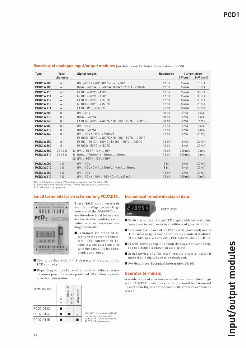
Small terminals for direct mounting PCD7.D16.. Economical remote display of data
PCD7.D120
■ Particularly bright, 6-digit LED display with decimal point. Very clear to read, even in conditions of poor visibility.
■ Does not take up one of the PCD’s serial ports; only needs 3 transistor outputs from the following standard modules: PCD2.A400 (inc. version Z06), PCD2.A460/..A465 or ..B100.
■ Parallel driving of up to 7 remote displays. The same value (up to 6 digits) is shown on all displays.
■ Serial driving of 2 (or more) remote displays: useful if more than 6 digits have to be displayed.
■ For details see Technical Information 26/361.
Operator terminalsA whole range of operator terminals can be supplied to go with SAIA®PCD controllers, from the small text terminal up to the intelligent control panel with graphics and touch-screen.
These SAIA® small terminals use the intelligence and large memory of the SAIA®PCD and are therefore ideal for use un-der favourable conditions with industrial controllers or in buil-ding automation.
■ Terminals are mounted di- rectly on the cover of control- lers. This combination re- sults in a compact controller with the capability for direct display and entry.
■ Text to be displayed (4 × 16 characters) is stored in the PCD controller.
■ Depending on the choice of terminal set, other commu-nications possibilities are produced. The following table provides information.
Overview of analogue input/output modules (for details see Technical Information 26/359)
Ausgabe 26/359 D1
Type Total Signal ranges Resolution Current draw channels 5 V bus ¹) 24 V bus ²)
PCD2.W100 4 I 0 V…+10 V / –10 V…0 V / –10 V…+10 V 12 bit 45 mA 15 mAPCD2.W105 4 I 0 mA…+20 mA ³) / –20 mA…0 mA / –20 mA…+20 mA 12 bit 45 mA 15 mA
PCD2.W110 4 I Pt 100: –50 °C…+150 °C 12 bit 45 mA 30 mAPCD2.W111 4 I Ni 100: –50 °C…+150 °C 12 bit 45 mA 30 mAPCD2.W112 4 I Pt 1000: –50 °C…+150 °C 12 bit 45 mA 20 mAPCD2.W113 4 I Ni 1000: –50 °C…+150 °C 12 bit 45 mA 20 mAPCD2.W114 4 I Pt 100: 0 °C…+350 °C 12 bit 45 mA 20 mA
PCD2.W200 8 I 0 V…+10 V 10 bit 8 mA 5 mAPCD2.W210 8 I 0 mA…+20 mA ³) 10 bit 8 mA 5 mAPCD2.W220 8 I Pt 1000: –50 °C…+400 °C / Ni 1000: –50 °C…+200 °C 10 bit 8 mA 16 mA
PCD2.W300 8 I 0 V…+10 V 12 bit 8 mA 5 mAPCD2.W310 8 I 0 mA…+20 mA ³) 12 bit 8 mA 5 mAPCD2.W340 8 I 0 V…+10 V / 0 mA…+20 mA ³) 12 bit 8 mA 20 mA Pt 1000: –50 °C…+400 °C / Ni 1000: –50 °C…+200 °CPCD2.W350 8 I Pt 100: –50 °C…+600 °C / Ni 100: –50 °C…+250 °C 12 bit 8 mA 30 mAPCD2.W360 8 I Pt 1000: –50 °C…+150 °C 12 bit 8 mA 20 mA
PCD2.W500 2 I + 2 O I: 0 V….+10 V / –10 V…+10 V 12 bit 200 mA 0 mAPCD2.W510 2 I + 2 O I: 0 mA….+20 mA ³) / –20 mA….+20 mA 12 bit 200 mA 0 mA O: 0 V….+10 V / –10 V…+10 V
PCD2.W400 4 O 0 V…+10 V 8 bit 1 mA 30 mAPCD2.W410 4 O 0 V…+10 V / 0 mA…+20 mA / +4 mA…+20 mA 8 bit 1 mA 30 mA
PCD2.W600 4 O 0 V…+10 V 12 bit 4 mA 20 mAPCD2.W610 4 O 0 V…+10 V / –10 V…+10 V / 0 mA…+20 mA 12 bit 110 mA 0 mA
¹) Current draw from internal 5 V bus, loading capacity max.750 mA for PCD1²) Current draw from internal 24 V bus, loading capacity max. 100 mA for PCD1³) +4…+20 mA via user program
With PCD1 the additional RS 485 interfaces are not available. On PCD1.M110 only terminal set PCD7.D162 may be used.
Terminal set
PCD7.D162 ■ – –PCD7.D164 ■ ■ –PCD7.D165 ■ – ■
..D16
0
PR
OFI
BU
S D
P
as s
lave
L ON
WO
RK
S®
Inpu
t/ou
tput
mod
ules
Smar
t so
luti
ons
for
com
fort
an
d sa
fety
141.4 5.5 64
34125
Ø 4.5
208
67 1
7
200
84
F1 F2 F3 F4 F5
95
8
2 ×
35 m
m
Saia-Burgess Controls Ltd.Bahnhofstrasse 18CH-3280 Murten / Switzerland
Telephone ++41 26 672 71 11Telefax ++41 26 670 44 43
E-mail: [email protected]: www.saia-burgess.comSupport: www.sbc-support.ch
Saia-Burgess Controls Kft.Liget utca 1H–2040 Budaörs
Telephone 023 / 501 170Telefax 023 / 501 180
E-mail: [email protected]: www.saia-burgess.huSupport: www.sbc-support.ch
Your local contact:
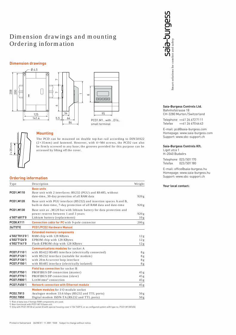
Dimension drawings and mountingOrdering information
Printed in Switzerland 26/350 E1 11. 2001 TA30 Subject to change without notice.
Dimension drawings
PCD1.M1.. with ..D16..small terminal
Ordering informationType Description Weight
Base units PCD1.M110 Base unit with 2 interfaces: RS 232 (PGU) and RS 485, without date-time, 30-day protection of all RAM data 920 g
PCD1.M120 Base unit with PGU interface (RS 232) and insertion spaces A and B, built-in date-time, 7-day protection of all RAM data and date-time 920 g
PCD1.M130 Base unit as ..M120 but with lithium battery for data protection and power reserve between 1 and 3 years 920 g4’507’4817’0 Lithium battery (replacement) 10 g
PCD8.K111 Connection cable for PC with 9-pole connector 200 g
26/737 E PCD1/PCD2 Hardware Manual
Extended memory components4’502’7013’0 ¹) RAM chip with 128 KBytes 12 g4’502’7126’0 EPROM chip with 128 KBytes 12 g4’502’7141’0 Flash-EPROM chip with 128 KBytes 12 g
Communications modules for socket APCD7.F110 ²) with RS 422/RS 485 interface (electrically connected) 8 gPCD7.F120 ²) with RS 232 interface (suitable for modem) 8 gPCD7.F130 ²) with 20 mA current loop interface 8 gPCD7.F150 ²) with RS 485 interface (electrically isolated) 8 g
Field bus connection for socket BPCD7.F750 ²) PROFIBUS DP connection (master) 45 gPCD7.F770 ²) PROFIBUS DP connection (slave) 45 gPCD7.F800 ²) LONWORKS® connection 45 g
PCD7.F650 ³) Network connection with Ethernet module 45 g
Modem modules for I/O module socketPCD2.T813 Analogue modem 33.6 kbps (RS 232 and TTL ports) 50 gPCD2.T850 Digital modem ISDN-TA (RS 232 and TTL ports) 50 g¹) Risk of data loss if foreign RAM components are used.²) Non-functional with PCD1.M110 base unit.³) Only with PCD1.M130 at socket B with special housing cover 4’104’7409’0, or as configured system with type no. PCD1.M130F650.
MountingThe PCD can be mounted on double top-hat rail according to DIN 50 022 (2 × 35 mm) and fastened. However, with 4 × M4 screws, the PCD2 can also be firmly screwed to any base; the grooves provided for this purpose can be accessed by lifting off the cover.