convection section failure analysis and fitness-for ... · convection section failure analysis and...
TRANSCRIPT
www.QuestIntegrity.com
Convection Section Failure Analysis and Fitness-for-Service Assessment*
“We had a failure of convection tubes in our furnace. Can we restart and continue to operate until our next planned shutdown?”
A brittle fracture failure of several HK-40 tubes in a convection section occurred in 2012. The failed convection section tubes were removed and submitted for metallurgical failure analysis. Hydrotesting was performed on the remaining tubes in the convection section to confirm that additional tubes were not substantially damaged and return the furnace to operation without further repairs. A failure analysis and API 579 Fitness-for-Service assessment were performed to determine the mode of failure and to determine the remaining life of the HK-40 tubes. The remaining life assessment determined the permissible existing flaw sizes in the tubes, which would not grow to a critical flaw prior to a future shutdown date. Several shutdown dates were evaluated to determine the timing of the next shutdown. This information provided the operator with a sound basis to evaluate the business and safety risks of continued operation until long-term repairs and system improvements could be implemented.
James R. Widrig Neil Schroetlin Quest Integrity Group, LLC Dakota Gasification Company
*Presented at the 2014 AIChE Annual Safety in Ammonia Plants and Related Facilities Symposium
Introduction
n-service equipment failures present a con-siderable challenge to reliability engineers. Since these events are unplanned, the spare parts and resources to quickly and efficient-
ly make repairs may not be readily available. Facility management is faced with making deci-sions to perform short-term repairs to equipment to safely operate until repair parts, equipment, manpower and product supply permit an ex-tended outage and long-term repair. In these in-stances, the reliability engineer will need to an-swer the question, “We had a failure of
convection tubes in our furnace. Can we restart and continue to operate until our next planned shutdown?”
Background
Dakota Gasification Company owns and oper-ates the Great Plains Synfuels Plant located near Beulah, North Dakota. The Synfuels Plant is the only commercial-scale coal gasification plant in the United States that manufactures natural gas. Each day the Synfuels Plant converts approxi-mately 18,000 tons of lignite coal into an aver-age 145 million cubic feet of synthetic natural gas for home heating and electricity generation.
I

www.QuestIntegrity.com
In addition to synthetic natural gas, the Great Plains Synfuels Plant produces numerous prod-ucts from the coal gasification process that have added great diversity to the plant's output. One of the products produced is anhydrous ammo-nia; Dakota Gasification Company has the abil-ity to produce about 400,000 tons per year. The processing steps used to produce anhydrous ammonia are (see Figure 1): (1) Rectisol synthesis gas, air and steam are heated by a fired heater using synthetic natural gas as a fuel. These heated gases are introduced into (2) the reformer where the methane is con-verted to carbon monoxide, carbon dioxide and hydrogen. The exit gases from the reformer en-ter (3) shift conversion where the carbon mon-oxide and water react to form hydrogen and car-bon dioxide. In the (4) carbon dioxide removal vessel, an absorption process is used to remove the carbon dioxide. The stream from the carbon dioxide removal system still contains small amounts of carbon monoxide and carbon diox-ide so it is sent through (5) the methanator where they react with hydrogen to form me-thane. Before the stream can be introduced to the ammonia synthesis loop, the (6) dryers and cold box remove water and methane along with excess nitrogen so that the hydrogen and nitro-gen ratio equals three to one. (7) The synthetic gas compressor takes the fresh feed from the cold box plus the ammonia loop recycle stream and compresses it to 2,500 psig. As the stream travels through (8) the radial flow ammonia converter, the hydrogen and nitrogen react to form ammonia. (9) The ammonia recovery unit then cools the stream and the liquid ammonia is sent to the 30,000 ton ammonia tank where it is stored until it is sold. The recycle gases are then returned to the synthetic gas compressor for re-introduction into the ammonia converter.
Figure 1 - Dakota Gasification Anhydrous Ammonia Process Diagram The Ammonia Plant Feed Gas Heater, BA-4403, is a multiple service, balanced draft, single cell, vertical cylindrical heater. The convection sec-tion preheats Rectisol synthesis gas (syngas), air and the syngas/steam mixture in separate con-vection section coils prior to conversion in the reformer reactor (similar in design to a second-ary reformer). The heater has a radiant section with two coils. One coil is used for steam gener-ation the second for final pre-heating of the syn-gas /steam mixture before reforming.
Tube Failure and Analysis
On April 15, 2012, the Ammonia Plant Feed Gas Heater sustained a tube failure (Tube 15V) in Lower Convection Section 1, the Lower Rec-tisol/Steam Coil. The failure occurred in one of the eight passes in the second row of finned tubes (from coil inlet) near the top of the lower convection section (see Figure 2, Figure 3, and Figure 4).
www.QuestIntegrity.com
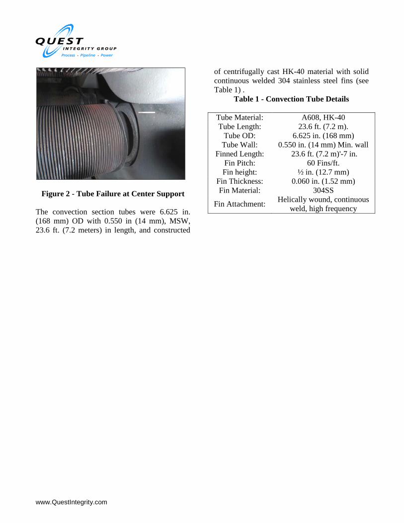
Figure 2 - Tube Failure at Center Support The convection section tubes were 6.625 in. (168 mm) OD with 0.550 in (14 mm), MSW, 23.6 ft. (7.2 meters) in length, and constructed
of centrifugally cast HK-40 material with solid continuous welded 304 stainless steel fins (see Table 1) .
Table 1 - Convection Tube Details Tube Material: A608, HK-40 Tube Length: 23.6 ft. (7.2 m).
Tube OD: 6.625 in. (168 mm) Tube Wall: 0.550 in. (14 mm) Min. wall
Finned Length: 23.6 ft. (7.2 m)'-7 in. Fin Pitch: 60 Fins/ft. Fin height: ½ in. (12.7 mm)
Fin Thickness: 0.060 in. (1.52 mm) Fin Material: 304SS
Fin Attachment: Helically wound, continuous weld, high frequency

www.QuestIntegrity.com
Figure 3 - Convection Tube Failure Location

www.QuestIntegrity.com
Figure 4 - Convection Section, Side View Results indicate that finned convection Tube 15V failed by tensile overload from a through wall crack near the “hot face” of the tube. The brittle fracture occurred through the circumfer-ential tube weld at the center of the tube located at the middle tube support (see Figure 5Error! Reference source not found.). The weld was embrittled by sigma phase (σ) that results in a loss of fracture toughness in heat resistant cast-ings from elevated temperature exposure. The tube bundle is supported by three tube sheets (tube supports), two on the ends and one in the middle. Subsequent inspection identified that both end tube supports had dropped down due to failure of the four support bolts (two for each end support). The loss of tube support at the end tube sheets resulted in the tube coil hav-ing a high tensile stress, with a bending and pos-sibly a torsional component, on the top of the tubes at the failure site(s) along the middle sup-
port. It is unlikely that the failure of Tube 15V caused the supporting bolts on the end tube sheets to fail. This is due to the location of the observed failure on the top of the tube. (The bolt failure is discussed in a later section of this pa-per.)
Figure 5 - Cross Section of Fracture Surface
www.QuestIntegrity.com
The tube coil had been in-service since 2003. The operating temperature near the outlet of the tube is ~1,255°F (680°C) and the maximum de-sign tube wall temperature is 1,482°F (806°C). This is sufficient time at temperature to form sigma phase in HK-40 castings. Also, welds typically have high ferrite content and are there-fore susceptible to sigma phase formation. The base metal microstructure showed no evidence of prolonged overheating above the design tem-perature.
Repairs and Testing
Dakota Gasification Company (DGC) had an inventory of replacement tubes for the convec-tion section to allow for immediate replacement of several tubes. During the removal of the damaged tube and an adjacent tube (found to be cracked on the outside), no additional tubes were found to be cracked by visual inspection. However, the full extent of the tube cracking was unknown from the inspection due to the configuration of the convection section and the use of finned tubes. Visual or NDT testing of the tubes would be difficult or impossible with-out the removal of a substantial number of tubes. Visual inspection, dye penetrant inspec-tion or a proof hydrotest would only locate tubes which had through wall cracks or tubes where cracking could be located on the external sur-face. Existing cracks which were not through wall or initiated from the ID could not be found with confidence using these conventional meth-ods. The Failure Assessment Diagram (FAD) Method Rather than proceeding with a full repair, a hy-drotesting procedure was developed using frac-
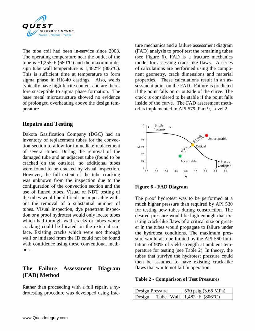
ture mechanics and a failure assessment diagram (FAD) analysis to proof test the remaining tubes (see Figure 6). FAD is a fracture mechanics model for assessing crack-like flaws. A series of calculations are performed using the compo-nent geometry, crack dimensions and material properties. These calculations result in an as-sessment point on the FAD. Failure is predicted if the point falls on or outside of the curve. The crack is considered to be stable if the point falls inside of the curve. The FAD assessment meth-od is implemented in API 579, Part 9, Level 2.
Figure 6 - FAD Diagram The proof hydrotest was to be performed at a much higher pressure than required by API 530 for testing new tubes during construction. The desired pressure would be high enough that ex-isting crack-like flaws of a critical size or great-er in the tubes would propagate to failure under the hydrotest conditions. The maximum pres-sure would also be limited by the API 560 limi-tation of 90% of yield strength at ambient tem-perature for testing (see Table 2). In theory, the tubes that survive the hydrotest pressure could then be assumed to have existing crack-like flaws that would not fail in operation. Table 2 - Comparison of Test Pressures Design Pressure 530 psig (3.65 MPa) Design Tube Wall 1,482 ºF (806°C)
www.QuestIntegrity.com
Temperature Minimum Test Pres-sure
1,460 psig (10.07 MPa)
Maximum Test Pres-sure
6,630 psig 45.7 MPa)
Proof Test Pressure 3,500 psig (24.1 MPa) The following are example calculations and as-sumptions used to define the test conditions: Basic Inputs:
• OD = 6.625 in.(168 mm), t = 0.55 in. (14 mm)
• Assumed crack dimensions: 5 in. (127 mm) long x 0.3 in. (7.6 mm) deep.
• Assumed fracture toughness: 14 ksi √in. (approximately ½ the toughness of car-bon steel at a cryogenic temperature).
Case 1: Hydrostatic Test at Ambient Tempera-ture.
• Assumed test pressure = 3,500 psig (24.1 MPa).
• Ambient temperature yield = 44 ksi (300 MPa)
• The weight of the water in the tube bun-dle was not considered in the calcula-tions.
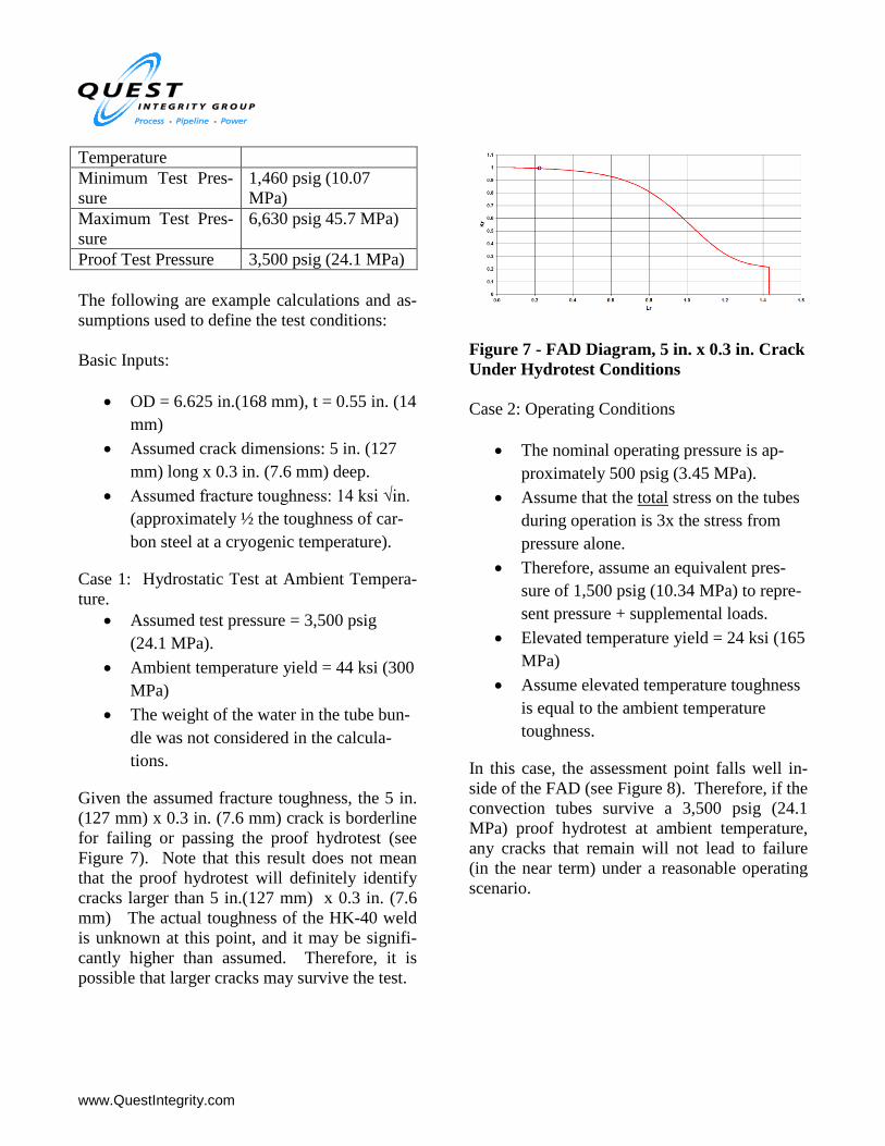
Given the assumed fracture toughness, the 5 in. (127 mm) x 0.3 in. (7.6 mm) crack is borderline for failing or passing the proof hydrotest (see Figure 7). Note that this result does not mean that the proof hydrotest will definitely identify cracks larger than 5 in.(127 mm) x 0.3 in. (7.6 mm) The actual toughness of the HK-40 weld is unknown at this point, and it may be signifi-cantly higher than assumed. Therefore, it is possible that larger cracks may survive the test.
Figure 7 - FAD Diagram, 5 in. x 0.3 in. Crack Under Hydrotest Conditions Case 2: Operating Conditions
• The nominal operating pressure is ap-proximately 500 psig (3.45 MPa).
• Assume that the total stress on the tubes during operation is 3x the stress from pressure alone.
• Therefore, assume an equivalent pres-sure of 1,500 psig (10.34 MPa) to repre-sent pressure + supplemental loads.
• Elevated temperature yield = 24 ksi (165 MPa)
• Assume elevated temperature toughness is equal to the ambient temperature toughness.
In this case, the assessment point falls well in-side of the FAD (see Figure 8). Therefore, if the convection tubes survive a 3,500 psig (24.1 MPa) proof hydrotest at ambient temperature, any cracks that remain will not lead to failure (in the near term) under a reasonable operating scenario.

www.QuestIntegrity.com
Figure 8 - FAD Diagram of 3 in. x 0.3 in. Crack Under Operating Conditions The proof hydrotesting of the furnace tubes was accomplished by testing each of the eight passes in the convection coil at 3,500 psig (24.1 MPa) and holding the pressure for one hour. During the testing, one additional tube failed at 900 psig (6.2 MPa) and was replaced. The tube was re-moved and the failure location was preserved for failure analysis. Upon completion of the hydrotesting, the fur-nace was successfully returned to operation on May 20, 2012. However, these repairs were considered temporary.
When Should We Plan for Replacement of the Tubes?
The initial tube failure event likely resulted in additional crack-like flaws in surrounding tubes. Further failure analysis and engineering assess-ment were planned to fully understand the root cause of the failures and to determine the re-maining life of the convection coil tubes. The desired outcome of the failure analysis and engineering assessment was to determine if the convection tubes were fit to operate until either of two future shutdown opportunities in No-vember 2012 or June 2013. Material Testing
In order to accurately calculate critical flaw siz-es, material properties such as toughness, yield strength and ultimate tensile strength must be identified. These material properties were ob-tained by destructive tests from tube samples removed from the heater. Maximum Possible Existing Flaw Sizes Maximum possible existing flaw sizes in the tubes were calculated using the material proper-ties data obtained from the ex-service tube. The analysis used Quest Integrity Group’s commer-cial software Signal™ Fitness-For-Service[2], a Windows® based program that uses the calcula-tion guidelines contained in the British Stand-ards BS-7910 and API 579/ASME FFS-1 [3]. Critical Crack Size Curves The result of this analysis is a plot of flaw depth (a) versus flaw length (2c) for an assumed ellip-tical surface flaw. Additionally, it is possible for a 360 º surface flaw to exist in the tubes. This analysis was also done in order to identify a crit-ical depth for a 360º surface flaw. Figure 9 shows the resulting critical crack size curve. The critical 360º flaw is plotted with a flaw length equal to the outer circumference of the tube. These flaw sizes represent the maximum possi-ble flaw sizes that could withstand hydrotest conditions of 3,500 psig (24.1 MPa) and a tem-perature of 70 °F (21°C).

www.QuestIntegrity.com
Figure 9 - Critical Existing Flaw Sizes, Calcu-lated from Hydrotest Conditions Any combination of flaw depth and flaw length that falls on or below the curve can exist in the tubes. The actual possible crack configurations could not be narrowed down beyond this due to the limitations of “back-calculating” an existing flaw size from hydrotest conditions. Extent of Existing Flaw Size In theory, it is possible that a long and shallow crack or a 360º surface crack would exist in the tubes that passed the proof test. However, a qualitative conclusion regarding which flaw length/depth combinations are more likely to occur can be reached based upon the axial stress profile of the tubes. The axial stress due to bending at the top of the pipe cross-section is tensile, while the axial stress due to bending at the bottom of the pipe cross section is compressive. This results in the overall axial stress that tends to grow a crack being higher at the top of the pipe cross-section than at the bottom leading to the identification of the likely and unlikely crack growth scenari-os shown in Figure 10.
Figure 10 - Possible Crack Growth Scenarios for Existing Flaws in Convection Tubes
Another factor that supports the idea that the ex-isting flaws in the tubes are more likely to be shorter and deeper can be drawn from the prob-able cause of the crack formation. The existing flaws were probably initiated and propagated significantly when a tube sheet support failed and overloaded the welds in the tubes. Alterna-tively, the crack may have grown after the tube sheet failure due to tube vibration. Such a sce-nario would cause the crack to break through at the 12 o’clock position rather than grow as a circumferential surface crack. The cracks ob-served in the sampled tubes that failed the hy-drotest at 900 psig supports the hypothesis that cracks will be shorter and deeper rather than longer and shallower.
Remaining Life of Maximum Possible Existing Flaw Sizes
Metals subjected to high temperatures and stresses will creep over time. Many methods ex-ist for characterizing creep behavior. The work described in this paper utilize the MPC Omega method which allows calculation of the creep life, strains and strain rates and incorporates the acceleration of creep toward the end of life. Creep Crack Growth Properties Using the material specific Omega law proper-ties identified in the previous section, a creep crack growth rate (da/dt and dc/dt) was calculat-

www.QuestIntegrity.com
ed. The creep crack growth rate is modeled us-ing a power law equation:
𝑑𝑎𝑑𝑡
= 𝐻 ∙ 𝐶𝑡𝑞
The quantity Ct is referred to as the “power re-lease rate” and is derived from the stress intensi-ty factor. This value is calculated from the stress profile at the crack tip. The H and q quantities are constants. Results The remaining life was calculated for eight of the critical flaw sizes (2c vs. a pairs) identified from the hydrotest results. Table 3 lists these flaw sizes. Table 3 - Maximum Critical Flaw Sizes
Flaw ID
Flaw Length, 2c (in.)
Flaw Depth, a (in.)
1 10.6 0.449 2 10.0 0.450 3 9.48 0.450 4 9.02 0.451 5 8.22 0.452 6 8.02 0.452 7 7.55 0.453 8 7.35 0.453
See Figure 11 for the corresponding crack growth versus time plots.
Figure 11 - Crack Growth Versus Time for the Maximum Possible Existing Flaw Sizes
These curves terminate at a point that represents 100% of the remaining creep life. It is recom-mended that the 80% remaining life be used to determine the remaining life of the flaw. This is due to the fact that towards the end of life the crack growth becomes very rapid. Once the crack begins to grow more rapidly, any change in operating conditions could cause the crack to become unstable and lead to sudden failure. Ta-ble 4 provides the remaining life values for the eight critical flaw sizes analyzed. Table 4 – Remaining Life for Critical Flaw Sizes
Any surface flaw with a length, 2c less than or equal to 7.35 in.(186.7 mm) (127° around cir-cumference) would operate safely until June 2013 while any surface flaw with a length, 2c less than or equal to 8.22 in. (208.8 mm) (142°
www.QuestIntegrity.com
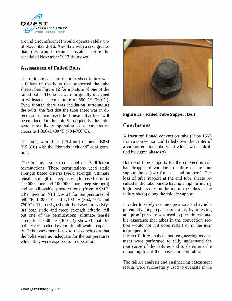
around circumference) would operate safely un-til November 2012. Any flaw with a size greater than this would become unstable before the scheduled November 2012 shutdown. Assessment of Failed Bolts The ultimate cause of the tube sheet failure was a failure of the bolts that supported the tube sheets. See Figure 12 for a picture of one of the failed bolts. The bolts were originally designed to withstand a temperature of 680 °F (360°C). Even though there was insulation surrounding the bolts, the fact that the tube sheet was in di-rect contact with each bolt means that heat will be conducted to the bolt. Subsequently, the bolts were most likely operating at a temperature closer to 1,300-1,400 °F (704-760°C). The bolts were 1 in. (25.4mm) diameter B8M (SS 316) with the “threads included” configura-tion. The bolt assessment consisted of 13 different permutations. These permutations used static strength based criteria (yield strength, ultimate tensile strength), creep strength based criteria (10,000 hour and 100,000 hour creep strength) and an allowable stress criteria (from ASME, BPV Section VIII Div 2) for temperatures of 680 °F, 1,300 °F, and 1,400 °F (360, 704, and 760°C). The design should be based on satisfy-ing both static and creep strength criteria. All but one of the permutations (ultimate tensile strength at 680 °F (360°C)) showed that the bolts were loaded beyond the allowable capaci-ty. This assessment leads to the conclusion that the bolts were not adequate for the temperatures which they were exposed to in operation.
Figure 12 - Failed Tube Support Bolt Conclusions A fractured finned convection tube (Tube 15V) from a convection coil failed down the center of a circumferential tube weld which was embrit-tled by sigma phase (σ). Both end tube supports for the convection coil had dropped down due to failure of the four support bolts (two for each end support). The loss of tube support at the end tube sheets re-sulted in the tube bundle having a high primarily high tensile stress on the top of the tubes at the failure site(s) along the middle support. In order to safely resume operations and avoid a potentially long repair timeframe, hydrotesting at a proof pressure was used to provide reasona-ble assurance that tubes in the convection sec-tion would not fail upon restart or in the near term operation. Further failure analysis and engineering assess-ment were performed to fully understand the root cause of the failures and to determine the remaining life of the convection coil tubes. The failure analysis and engineering assessment results were successfully used to evaluate if the

www.QuestIntegrity.com
convection tubes were fit to operate until either of two future shutdown opportunities in No-vember 2012 or June 2013. The methods discussed in this paper exemplify how failure analysis and fitness-for-service pro-vided the operator a sound basis to evaluate the business and safety risks of continued operation until long-term repairs and system improve-ments could be implemented.
References
The American Petroleum Institute and The American Society of Mechanical Engineers, Fitness-for-Service API 579/ASME FFS-1 (API 579 Second Edition). © API Publishing Ser-vices June 5, 2007. ASME (2010), “ASME Boiler and Pressure Vessel Code”, Section VIII, Division 2, the American Society of Mechanical Engineers, New York, NY.