conventional and nonconventional repair of curtain...
TRANSCRIPT

ConvenTional and nonConvenTional
repair of CurTain Wall SYSTeMS
KAmRAn FARAhmAnDPouR, FRCi, RRC, RWC, REWC, RBEC, PE, CCs, CCCA, FnAFE
buildiNG teChNoloGy CoNsultaNts, pC 1845 E. Rand Road, Arlington Heights, Illinois 60004
Phone: 847-454-8814 • Fax: 847-454-8801 • E-mail: [email protected]
S y m p o S i u m o n B u i l d i n g E n v E l o p E T E c h n o l o g y • n o v E m B E r 2 0 1 5 F a r a h m a n d p o u r • 5 5

ABsTRACT
This paper will cover the typical failure mechanisms in curtain wall systems, the conventional repair approaches, and a discussion of advantages and disadvantages of each repair approach.
A case history involving nonconventional repairs to a large commercial building curtain wall system will be presented. These repairs included retrofitting an existing curtain wall system with new custom-extruded external pressure bars and caps to address several issues, correcting displaced mullions, and replacing mechanical louvers integrated into the curtain wall system. The repairs also included overcladding the barrier panels between curtain wall sections with a new system that incorporated an air and water-resistive barrier and a drainage plane.
sPEAKER
kamraN FarahmaNdpour, FrCi, rrC, rWC, reWC, rbeC, pe, CCs, CCCa, FNaFe — buildiNG teChNoloGy CoNsultaNts, pC
KAMRAn FARAHMAndPOUR is the principal of Building Technology Consultants, PC. He specializes in the forensic investigation and repair of building envelope systems. Kami is a Fellow of RCI and a Fellow of the national Academy of forensic Engineers. He has served on many technical committees and boards of directors of various organizations. His involvement with the building envelope industry has earned him many awards—both for his contributions to the industry, and for his work on various projects.
5 6 • F a r a h m a n d p o u r S y m p o S i u m o n B u i l d i n g E n v E l o p E T E c h n o l o g y • n o v E m B E r 2 0 1 5
ConvenTional and nonConvenTional
repair of CurTain Wall SYSTeMS
ABSTRACT Many buildings built in the late 20th
and early 21st centuries included glass and metal curtain walls. Some of these buildings are approaching the age when deterioration of glazing gaskets and internal curtain wall seals can result in leaks. In other buildings, fading of exterior components, failure of insulated glass units, and/or the need to improve energy efficiency is necessitating major rehabilitation of these curtain walls.
This paper will summarize the typical failure mechanisms in curtain wall systems, the conventional repair approaches, and a discussion of advantages and disadvantages of each repair approach. For a more detailed discussion of deterioration mechanisms in curtain wall systems, refer to SWR Institute’s A Practical Guide to Waterproofing Exterior Walls, Chapter 4.
A case history involving nonconventional repairs to a large commercial building curtain wall system will be presented. These nonconventional repairs included retrofitting the curtain wall system with new custom-extruded external pressure bars and caps to address several issues, correcting displaced mullions, and replacing mechanical louvers integrated into the curtain wall system. The repairs also included over-cladding the decorative metal cladding panels between curtain wall sections with a new system that incorporated an air and water-resistive barrier, and a drainage plane.
INTRODUCTION Glass and metal curtain wall systems
have been used to construct all or portions of building exterior walls since the mid1900s. new innovations in glass, glazing, and thermal technologies have improved the performance of these systems over the years. Modern curtain wall systems provide many advantages such as improved aesthetics, lighter weight, rapid construction, flexibility in design, abundant daylighting, and even improved thermal performance. Although older glass technologies such as insulated glass units (IGUs) helped improve the thermal performance of curtain wall
and window systems, recent advancements including low-e coatings and low-conductivity gas fills have helped glazed systems achieve more acceptable thermal performance for the exterior walls.
Early curtain wall systems did not include insulated glass and were constructed of steel framing members. newer systems include variations of IGUs and thermally broken aluminum frame systems. Typically, thermal performance, water and air infiltration resistance, fabrication and erection methods, and structural performance requirements dictate the type of curtain wall system that is selected for each application. Obviously, cost is also a consideration, but should not override the importance of system performance.
The thermal performance of a curtain wall system is a function of its framing assembly and glazing. Although possible, upgrading the framing systems is costly and not practical in many cases. Upgrading the glazing is typically more feasible, depending on the original design of the glazing pocket and the system’s framing.
Curtain wall systems are different from storefronts and many windows in that they incorporate elaborate internal drainage mechanisms and often include pressure equalization and complex water management technologies to reduce potential for water infiltration.
Water infiltration and air infiltration resistance of curtain wall systems typically depend on the integrity of their glazing seals and internal drainage system. The outer glazing seal system typically provides the first line of defense against water infiltration, while the interior glazing seals provide resistance against air infiltration, a critical aspect of pressure equalization. The internal drainage system typically consists of end dams or zone dams at ends of each horizontal mullion, and weeps that allow for water to drain to the exterior. Deterioration of exposed sealant joints can also impact water and air infiltration resistance of a curtain wall or window system.
Typically, the aesthetics of the system are dictated by the overall design of the
framing system, feature strips (metal cladding panels integrated into the design of the curtain wall system), and glass appearance. Changing the configuration of a curtain wall’s framing system is usually not practical. However, changing glazing will typically provide an opportunity to upgrade the system’s appearance. Retrofitting the framing or replacement of exterior mullion caps can also provide an opportunity to change or upgrade the appearance of the system.
DETERIORATION MECHANISMS IN GLAZED SYSTEMS
Typical deterioration mechanisms of curtain wall and window systems can be divided into the following three categories:
Aesthetics Degradation The aesthetics of a curtain wall system
can be adversely affected by long-term exposure to elements. Such degradation can consist of fading or peeling of metal frame finishes, as well as staining of glass and metal components due to sealant plasticizer migration or etching of the glass and metal because of alkalinity of adjacent cementitious materials.
Fading of metal frame systems is directly related to the quality of finishes and exposure to ultraviolet (UV). Peeling of metal finishes can be due to improper surface preparation during the original coating process, or exposure to salts in service (such as areas of curtain walls in coastal environments, or those adjacent to walks where deicing salts are used).
Glass staining is sometimes referred to as “picture framing.” This phenomenon has been well-documented and is typically due to migration of plasticizers from older silicone sealants that may have been used as glazing, used in repairs, or used in adjacent joints. This phenomenon can also impact the metal framing components.
Water and Air Infiltration Issues Water and air infiltration issues are
some of the most common problems with curtain wall systems. When manifested
S y m p o S i u m o n B u i l d i n g E n v E l o p E T E c h n o l o g y • n o v E m B E r 2 0 1 5 F a r a h m a n d p o u r • 5 7

in recently installed curtain wall systems, they are typically indicative of installation or design issues. However, as properly designed and installed curtain wall systems approach 20 or more years in service, many of their internal seals and exterior weather seals deteriorate, resulting in air and/ or water infiltration issues. Other factors such as deterioration of expansion joints can also lead to air and/or water infiltration problems.
Glazing Gaskets One of the most common deterioration
mechanisms in curtain wall systems is the degradation of glazing gaskets. Most curtain wall systems rely on preformed gaskets for a watertight seal between the glass or spandrel panels and metal components. These gaskets serve as the primary seal against air and water infiltration. Glazing gaskets are made of various materials, including neoprene, EPdM, silicone, and other elastomeric materials. Gaskets are either molded or extruded. Extruded gaskets have to be cut to length and jointed with adhesive at the mitered corners. In some cases, the corners are simply miter-cut at the appropriate angle and not adhered. In other cases, the gaskets may be cut at 90-degree angles and simply butted against the gasket on the adjacent side of the glazing. Molded gaskets have integrated mitered corners with no seams and typically provide a better seal at the corners.
Inside set-glass curtain wall systems
Photo 1 – Crazing of glazing gaskets in a curtain wall system.
Photo 2 – Shrinkage of glazing
gaskets.
typically incorporate a combination of a preset “bedding” gasket on the exterior, and a “drive-in” wedge gasket on the interior. Outside set-glass systems have a “bedding” gasket on the interior and a “drive-in” wedge gasket on the exterior. Preset gaskets can typically not be removed and replaced easily, while drive-in wedge gaskets can.
depending on gasket type, prolonged exposure to UV can result in hardening, shrinkage, and crazing (cracking) of the gasket material (Photos 1 and 2). In some cases, gasket shrinkage is significant enough that the gaskets shrink away from glass corners, resulting in loss of watertightness. Molded gaskets can pull out of their retaining grooves due to shrinkage, and extruded gaskets can simply shrink away from the corners, leaving the corners with no waterproofing protection (Photo 3). Although most curtain wall systems
incorporate internal weep systems, a weep system typically cannot accommodate significant water infiltration due to gasket deterioration and shrinkage.
Exterior Sealants and Expansion Joints Curtain walls systems also depend on
exterior sealants and expansion joints to prevent air and water infiltration. In fact, many building façades are comprised of curtain wall sections adjoining other types of cladding systems. In such systems, the exterior sealant joints between the curtain wall system and the adjacent cladding materials are critical in maintaining the watertight integrity of the façade. Sealants are also used to form expansion joints within the curtain wall systems.
A discussion of failure mechanisms in sealant joints is beyond the scope of this article. However, it should be noted that due to their low thermal mass, curtain wall systems are subject to frequent thermal movements. If sealant joints within the system or around the perimeter of the system are not designed properly, failures can occur. Proper design of the joint, proper selection of the sealant materials, and proper installation are key in ensuring long-term performance of the joints. Industry standards such as ASTM C1472,1 ASTM C1193,2 and SWR Institute’s “Sealants: The Professional’s Guide” provide good information on these topics.
Building expansion joint accessories are often incorporated into the building façade to accommodate building movements. If not properly integrated with the curtain wall system, or if not able to accommodate in-service movements, expansion joints can also be a source of water or air infiltration.
Photo 3 ––Extruded glazing gasket shrinkage.
5 8 • F a r a h m a n d p o u r S y m p o S i u m o n B u i l d i n g E n v E l o p E T E c h n o l o g y • n o v E m B E r 2 0 1 5

Internal Seals Most curtain wall systems rely on their
internal drainage system to accommodate incidental water that can bypass the primary seals. The internal drainage system typically consists of horizontal troughs formed by various framing members (often referred to as “glazing pockets”), end dams, or zone dams to control flow of water in those troughs, and sealants to ensure watertight integrity at various joints. In most cases, original deficiencies in the application of the internal seals may not manifest until the primary seals deteriorate sufficiently to allow a significant amount of water to enter the system. In other cases, material deterioration or movement at the connection can cause failure of the internal seals. Once internal seals fail, the drainage system will not be able to control incidental water, resulting in water infiltration.
Another issue with internal seals is the shrinkage of thermal breaks. Thermal breaks are incorporated in the same members that form the drainage troughs in the system. Once thermal breaks shrink, they result in either separation from the end dams or separation from the shoulders of the thermal break. In either case, water leakage can result.
Thermal Performance Issues Curtain wall systems can also suffer
from thermal performance issues. These issues can result in excessive energy usage, condensation, and thermal discomfort for building occupants.
In most cases, thermal performance deficiencies are due to original design and construction of the system, and are not related to ongoing deterioration or aging. However, some in-service deterioration or damage can cause thermal performance issues. As examples, IGU seal failures can be considered a thermal performance issue that is a result of ongoing deterioration. Additionally, in-service damage to interior vapor retarders of spandrel panel insulation can also cause localized condensation.
Structural and Safety Issues Many other distress or deterioration
mechanisms in curtain wall systems can pose structural or safety concerns. These include, but are not limited to, loose mullion caps, glass breakage, and corroded or distressed connections.
Many curtain wall systems incorporate
snapped-on, prefinished aluminum extrusions that cover the mullions. Typically, these components only serve an aesthetic function and do not impact the performance of the system.3 However, in some thermally improved systems, mullion caps can contribute to additional thermal performance for the system. The proper fit of these components is dependent on tight manufacturing tolerances. Temperature changes, frequent removal and reinstallation, or improper manufacturing tolerances can result in dislodgement of these covers. If dislodged, mullion covers can pose a serious fall hazard.
As previously discussed, curtain wall systems are subjected to extreme thermal fluctuations. Unlike other building envelope systems such as masonry, stone, or concrete, curtain wall systems have a relatively small thermal mass. This characteristic results in rapid thermal changes in the system components. During a hot summer day, a portion of a dark curtain frame exposed to sunlight can reach 170ºF or more. While a masonry wall may take several hours to reach such peak temperatures, a curtain wall can reach these temperatures after a short period of exposure to sunlight on a warm summer day. Conversely, a curtain wall system can also cool rapidly due to its small thermal mass.
The small thermal mass of curtain wall systems, combined with extensive use of aluminum in curtain wall frames (aluminum has a relatively high coefficient of thermal expansion), make curtain wall systems particularly prone to thermal-induced deterioration. The thermal expansion of a 20-ft.-tall aluminum mullion subjected to a temperature range of -20 to 170ºF is over 5/8 inch. While the curtain wall system can undergo such significant movements, the structural frame of the building, which is protected from temperature fluctuations, undergoes very little thermal movement. This results in differential thermal movements between the curtain wall system and the building frame. Building frame deformations such as creep and deflections also exacerbate such differential movement between the curtain wall system and the building frame. The connections of the curtain wall system to the building frame must be designed to accommodate such movements, while properly transferring curtain wall gravity and wind loads to the building frame.
Thermal cycles can result in loosening of bolted connections to the building frame or failure of the connections. If not designed or installed properly, curtain wall framing members are overstressed, resulting in bowing or deformation to accommodate thermal movements.
In addition to thermal movements, attachment brackets can fail due to other causes, including the following:
1. Attachment brackets can fail due to improper design of the gravity support brackets. Typically, the gravity load of the curtain wall system is transferred to a limited number of attachment brackets within a section of the curtain wall, usually referred to as “dead-load connections.” The remaining brackets within that section of the curtain wall are designed to only resist wind loads and accommodate the in-plane thermal movements of the curtain wall system. These “wind-load connections” cannot support gravity loads. This typical configuration results in large gravity loads to be transferred to the dead-load connections. If not properly designed, the dead-load connections can fail. The failure may be in the form of complete fracture of the connection brackets, failure of the bolts, or yielding of the components.
2. One often overlooked failure mechanism is the failure of the connection brackets due to lateral thermal movements. As mentioned above, in most cases, the wind-load connection brackets are designed to accommodate vertical movements. However, they are not designed to accommodate horizontal movements. In such cases, the horizontal thermal movements are accommodated by flexing of the brackets. The author is familiar with projects at which building occupants have reported loud noises during periods of rapid temperature change. These noises have been traced to unaccommodated horizontal movement of the curtain wall system.
3. The attachment brackets can also fail due to corrosion. While most curtain wall components are constructed of corrosion-resistant components, the attachment brackets
S y m p o S i u m o n B u i l d i n g E n v E l o p E T E c h n o l o g y • n o v E m B E r 2 0 1 5 F a r a h m a n d p o u r • 5 9

Photo 4 – Premolded silicone boots used to seal framing joints.
regarding the repairs. This section focus
es on addressing water infiltration issues. For more information on repair approaches for other issues, refer to SWR Institute’s A Practical Guide to Waterproofing Exterior Walls, Chapter 4.
Conventional Water Infiltration Repairs Weep Cleaning and Baffle Replacement
Where the or anchors can be made of carbon steel without any corrosion protection. In combination with condensation or continued water leakage, such components can sufficiently corrode to cause failure of the connection. Another contributing factor is galvanic corrosion due to contact between dissimilar metals.
REPAIR APPROACHES FOR CURTAIN WALL SYSTEMS
Repair methodologies to address curtain wall issues can range from simple cleaning or sealing to complete replacement. This section provides a brief summary of typical repair approaches used to address various curtain wall issues.
Before any repair program can be undertaken, the scope of the project needs to be thoroughly defined through the investigative process. All too often, repairs have been undertaken to address one known symptom, only to find later that the root cause has not been addressed, and the original symptoms reappear. For this reason, it is important to understand the cause(s) of each encountered issue, so that an appropriate solution can be developed. It is also important to evaluate the effectiveness of each repair through mock-ups and verification testing.
Any repair design should consider costs, anticipated service life of the repairs, maintenance requirements for the repairs, reliability of the repairs in addressing the issues, and inconvenience to the building occupants. When developing repair alternatives, it is imperative to discuss the advantages and disadvantages of each repair approach with the building owner so that he or she can make an informed decision
system’s weeps and baffles are accessible, they can be cleaned to ensure optimum performance of the drainage system. In some cases, such cleaning may be sufficient to relieve the system of excessive water that results in interior leaks. If accessible, cleaning of the weeps and replacement of baffles can be far less costly than other repairs.
Wet Glazing One of the most common and least
expensive repair approaches to address curtain wall water infiltration issues is to seal all exposed glazing and frame joinery with sealant. This approach is typically referred to as “wet-sealing.” Wet-sealing involves application of sealant over glazing gaskets and at all other locations where water infiltration into the system can occur. Although sealing of exposed frame joinery need not necessarily be included in a wet-sealing project, it often is. Wet-sealing of glazing typically consists of cutting and removing the exterior portion of the glazing gaskets and applying a cap bead of sealant around the glazing. In addition, frame joinery can be sealed. However, in most cases, decorative mullion caps are not removed to seal frame joinery. Instead, sealant is applied at all mullion cap interfaces. Some wet-sealing projects involve the use of silicone strips or premolded silicone shapes to seal mullion and frame joinery (Photo 4).
The wet-sealing approach attempts to minimize the impact of internal seal issues by minimizing water penetrating into the system. Ideally, a wet-sealing repair renders the curtain wall system a barrier system. However, the success of wet-sealing is highly dependent upon workmanship and the geometry of sealant joints used for the wet-sealing project. Rarely, adequate geometry can be accomplished at exposed frame or mullion cap joinery that can accommodate differential movements between those components. In such cases, the use of silicone strips or premolded custom silicone boots can help provide for a watertight condition.
While wet-sealing can yield adequate results, it is often considered a shorter-term repair because it is highly dependent on performance of the sealant joints. Although the sealant materials used for the repairs can last more than 20 years, joint failures can occur due to improper geometry and/or workmanship issues. As such, wet-sealing is not considered a long-term solution to water infiltration issues. nonetheless, this approach can provide some building owners with an economically viable repair with a reasonable level of service.
Glazing Gasket Replacement Where severely deteriorated glazing gas
kets cause excessive water infiltration into the system, they can be replaced. Glazing gasket replacement poses some challenges. These include the difficulty in removal and replacement of preset gaskets. In such cases, deglazing (removal of IGU) may be necessary to accommodate gasket replacement.
Removal and replacement of glazing gaskets only on the exterior side of the system may not necessarily be sufficient. The inte-
Photo 5 – Repair of internal seals by deglazing.
6 0 • F a r a h m a n d p o u r S y m p o S i u m o n B u i l d i n g E n v E l o p E T E c h n o l o g y • n o v E m B E r 2 0 1 5
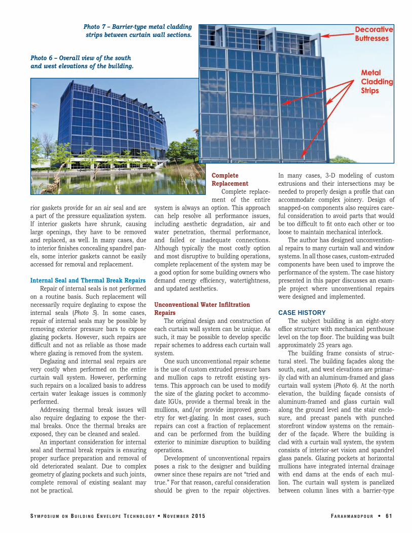
Photo 7 – Barrier-type metal cladding strips between curtain wall sections.
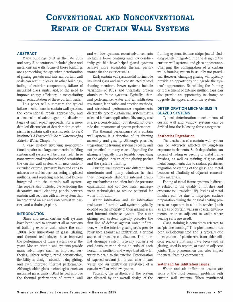
Photo 6 – Overall view of the south and west elevations of the building.
rior gaskets provide for an air seal and are a part of the pressure equalization system. If interior gaskets have shrunk, causing large openings, they have to be removed and replaced, as well. In many cases, due to interior finishes concealing spandrel panels, some interior gaskets cannot be easily accessed for removal and replacement.
Internal Seal and Thermal Break Repairs Repair of internal seals is not performed
on a routine basis. Such replacement will necessarily require deglazing to expose the internal seals (Photo 5). In some cases, repair of internal seals may be possible by removing exterior pressure bars to expose glazing pockets. However, such repairs are difficult and not as reliable as those made where glazing is removed from the system.
Deglazing and internal seal repairs are very costly when performed on the entire curtain wall system. However, performing such repairs on a localized basis to address certain water leakage issues is commonly performed.
Addressing thermal break issues will also require deglazing to expose the thermal breaks. Once the thermal breaks are exposed, they can be cleaned and sealed.
An important consideration for internal seal and thermal break repairs is ensuring proper surface preparation and removal of old deteriorated sealant. Due to complex geometry of glazing pockets and such joints, complete removal of existing sealant may not be practical.
Complete Replacement
Complete replacement of the entire
system is always an option. This approach can help resolve all performance issues, including aesthetic degradation, air and water penetration, thermal performance, and failed or inadequate connections. Although typically the most costly option and most disruptive to building operations, complete replacement of the system may be a good option for some building owners who demand energy efficiency, watertightness, and updated aesthetics.
Unconventional Water Infiltration Repairs
The original design and construction of each curtain wall system can be unique. As such, it may be possible to develop specific repair schemes to address each curtain wall system.
One such unconventional repair scheme is the use of custom extruded pressure bars and mullion caps to retrofit existing systems. This approach can be used to modify the size of the glazing pocket to accommodate IGUs, provide a thermal break in the mullions, and/or provide improved geometry for wet-glazing. In most cases, such repairs can cost a fraction of replacement and can be performed from the building exterior to minimize disruption to building operations.
Development of unconventional repairs poses a risk to the designer and building owner since these repairs are not “tried and true.” For that reason, careful consideration should be given to the repair objectives.
In many cases, 3-d modeling of custom extrusions and their intersections may be needed to properly design a profile that can accommodate complex joinery. design of snapped-on components also requires careful consideration to avoid parts that would be too difficult to fit onto each other or too loose to maintain mechanical interlock.
The author has designed unconventional repairs to many curtain wall and window systems. In all those cases, custom-extruded components have been used to improve the performance of the system. The case history presented in this paper discusses an example project where unconventional repairs were designed and implemented.
CASE HISTORY The subject building is an eight-story
office structure with mechanical penthouse level on the top floor. The building was built approximately 25 years ago.
The building frame consists of structural steel. The building façades along the south, east, and west elevations are primarily clad with an aluminum-framed and glass curtain wall system (Photo 6). At the north elevation, the building façade consists of aluminum-framed and glass curtain wall along the ground level and the stair enclosure, and precast panels with punched storefront window systems on the remainder of the façade. Where the building is clad with a curtain wall system, the system consists of interior-set vision and spandrel glass panels. Glazing pockets at horizontal mullions have integrated internal drainage with end dams at the ends of each mullion. The curtain wall system is panelized between column lines with a barrier-type
S y m p o S i u m o n B u i l d i n g E n v E l o p E T E c h n o l o g y • n o v E m B E r 2 0 1 5 F a r a h m a n d p o u r • 6 1

Photo 8 – Large HVAC louvers installed within the curtain wall framing.
deteriorated glazing gaskets, deteriorated or open sealant joints at barrier metal cladding (Photo 9), inadequate internal seals, open-frame joinery, displaced or rotated mullions, and extensive water leakage issues below the louver assemblies. In addition, dislodged and loose mullion caps were observed at several locations. Extensive water leakage below the louvers was also confirmed through water testing.
Repair Options Developed for the Building Owner
Based on the findings of decorative metal cladding system separating the curtain wall panels (Photo 7). The joints in the barrier metal cladding are sealed with field-applied liquid sealant. On the east and west elevations of the penthouse level, large aluminum louvers serving the HVAC equipment have been integrated into the curtain wall system (Photo 8).
On the south elevation, the building columns extended above a setback terrace area forming decorative buttresses (also Photo 8). These buttresses had been clad with a barrier-type prefinished aluminum cladding system.
The building had suffered from façade-related water leaks since its original construction. Most of the leaks were reported along the south and east elevations. The curtain wall-related water leakage had been so pervasive that plastic buckets had been placed along vision glass sills throughout the building. After each rainstorm, the building engineering staff reported hundreds of leaks throughout the areas clad with the curtain wall system.
The author’s firm was retained by the building owner’s architectural consulting firm to evaluate the water infiltration issues into the building and to develop repair recommendations.
The scope of the investigation consisted of review of the curtain wall shop drawings, a visual review of the building exterior, water testing, removal of mullion caps to examine frame joinery, and preparation of a report.
The investigation revealed several issues associated with the curtain wall system. These included faded aluminum finishes,
the investigation, four repair options were developed for the owner’s consideration. These repair options were as follows:
1. Option 1 – Surface Repairs: This option consisted of removal of the exposed portions of the glazing gaskets and application of sealant, replacement of sealant joints at barrier cladding system, and installation of custom-molded silicone boots at mullion cap intersections. The estimated cost of these repairs was $800,000 to $1,200,000.
2. Option 2 – Sealing Frame Joinery and Wet-Sealing: This option consisted of removal of the exposed portions of the glazing gaskets and application of a cap seal, at the replacement of sealant joints at barrier cladding system, removal of existing mullion caps to allow sealing of frame joinery, and attachment of new mullion caps. The estimated cost was $1,500,000 to $2,000,000. This option would provide for better aesthetics, improved durability, and improved reliability as compared to Option 1.
3. Option 3 – Retrofit With Custom-Extruded Components: This option consisted of removing the existing mullion caps, installing
a new custom-extruded pressure bar system over the existing frame, wet-sealing the perimeter of the glazing, providing a self-adhered air barrier over the existing barrier metal cladding, and over-cladding the metal cladding components with a drain-able cladding system. Estimated cost was $2,500,000 to $3,000,000. This option would provide for better aesthetics and improved durability and performance as compared to Option 2.
4. Option 4 – Complete Removal and Replacement: This option consisted of complete removal and replacement of the curtain wall system. The estimated cost for this work would exceed $10,000,000.
The advantages and disadvantages of the above options were discussed with the building owners on several occasions. The implementation of Option 4 would make it difficult to occupy the building during construction. As such, this option was eliminated in the early stages of discussions with the building owner. Of the remaining options, the advantages of Option 3 were most appealing to the building owner without a significant financial penalty. As such, the building owner opted to authorize the design and implementation of Option 3.
Design of Repairs Figure 1 depicts the basic concept of
Option 3 repairs at a typical horizontal mullion. The repairs would consist of trimming the exposed portions of the glazing gaskets, removing the existing snapped-on mullion caps, cleaning the frame surfaces, installing a custom-extruded aluminum pressure bar set in sealant, applying perimeter glazing
Photo 9 – Failed sealant joint at decorative metal cladding joint.
6 2 • F a r a h m a n d p o u r S y m p o S i u m o n B u i l d i n g E n v E l o p E T E c h n o l o g y • n o v E m B E r 2 0 1 5

sealant, and installing a new custom-extruded, prefinished aluminum snapped-on cap. The new pressure bar would be 1/2 inch wider than the existing frame members, allowing a glazing sealant depth of 1/4 inch. In addition, the new pressure bar sealant shoulder would be placed approximately 3/8 inch away from the exterior face of the IGU to allow for suitable sealant geometry. Such sealant geometry is far more reli- Figure 1 – Typical horizontal mullion. able than a sealant cap bead typically used for wet-seal repairs.
Once the new pressure bar was installed, weep holes would be drilled at the same locations as the existing weeps so that the internal water management of the system would function as originally intended.
Although the repair concept of Option 3 was relatively simple, adopting it to various details throughout the façade was challenging. These challenging details included the interface of the curtain wall at the barrier metal cladding areas, the configuration of the system at the HVAC louvers, and intersection of numerous extruded sections.
While these repairs would not address any of the internal seal issues within the system, they would provide for a reliable method of sealing the exterior face of the curtain wall system.
Figure 2 depicts the typical design detail at one of the horizontal decorative strips, which originally consisted of a barrier-type
Figure 2 – Typical horizontal metal cladding detail and drainage pattern.
perature of 160ºF (the surface of the curtain wall could reach 160ºF under warm, sunny conditions), and be compatible with the structural glazing sealant used to attach the spacer bars to the air barrier. After researching available products, an aluminum-faced rubberized asphalt membrane with a maximum in-service temperature of 230ºF was selected for the project. The aluminum facing of the product would make the product compatible with the specified
Figure 3A – Removal of existing louver.
metal cladding system. At those locations, a self-adhesive air barrier would be installed over the existing metal cladding and terminated below the outer lips of the new curtain wall pressure bars. Then, the new metal cladding panel would be installed over a series of vertical aluminum spacer bars. These bars were designed to provide a drainage cavity between the new air barrier and the back of the new metal cladding panels. That cavity was designed to weep to the exterior through the horizontal mullion cover below each strip. In order to avoid fastening the new metal spacers and cladding through the air barrier, the design team opted to use structural tape to adhere the spacer bars to the back of the new metal cladding in the shop, and structural glazing to adhere the assembly to the air barrier in the field.
One of the challenges was selection of an appropriate air barrier that could
resist the anticipated maximum tem-
Figure 3B – Sealing end of existing mullion.
S y m p o S i u m o n B u i l d i n g E n v E l o p E T E c h n o l o g y • n o v E m B E r 2 0 1 5 F a r a h m a n d p o u r • 6 3

Figure 3C – Installation of pan flashing.
Figure 3E – Installation of sealant for new pressure bars.
Figure 3D – Reinstallation of louver and
installation of air barrier.
Figure 3F – Installation of new pressure bars.
Figure 3G – Installation of glazing sealant. Figure 3H – Installation of new mullion caps.
structural silicone-glazing sealant. In order adhesive tapes or structural glazing failed. ensure water management below the louto provide redundancy for attachment of the Another challenge for the design team vers, the louvers would have to be removed new metal cladding panels, the design team was the configuration of the HVAC louvers. so that a pan flashing could be installed also ensured that the new metal cladding Field-testing has indicated extensive water below them. The louvers had originally been strips were captured by the mechanically leakage below the louvers. The interiors of installed from the interior. However, removattached pressure bars, making it impos- the louvers were either blanked off or direct- al of the louvers would require removal sible for them to dislodge in the event the ly connected to large ductwork. In order to of the interior ductwork that was deemed
6 4 • F a r a h m a n d p o u r S y m p o S i u m o n B u i l d i n g E n v E l o p E T E c h n o l o g y • n o v E m B E r 2 0 1 5

Figure 4 – Buttress base detail.
Figure 5 – Typical extrusion profile.
impractical. As such, the design team opted to trim the exterior flanges of the vertical mullions to allow removal of the louvers from the exterior of the building. Once the flanges were trimmed, the louvers could be disconnected from the interior duct-work and removed. The design documents included an alternate to replace the louvers with new high-performance louvers.
Figures 3A through 3H depict the sequence of work related to the louvers. Once the louvers were removed, a stainless steel pan flashing was designed to be installed below the louvers. Due to the complex geometry of the new pressure bars, the louvers, and their new pan flashing end dams, the louver assemblies and their surrounding curtain wall framing were modeled using 3-d solid modeling software. This modeling allowed the design team to evaluate the sequence of work during con
struction and to develop an appropr ia te end-dam configuration for the louver pan flashing.
Figure 4 depicts the configuration of new metal cladding at the seventh-floor terrace bu t t r e s s e s . The buttresses were treated similarly to other metal-
clad areas by installing an air barrier over the existing cladding, installing spacer bars, and installing new metal cladding over the spacer bars. Care was taken to ensure the gap between the new and existing metal cladding was drained to the exterior.
All in all, the design required 19 custom-extruded profiles. Figure 5 depicts the design details for a pressure bar and its companion cap. Those profiles were carefully designed to provide for sealant geometry and grooves in the components to allow field technicians to properly locate fasteners. In addition to the custom-extruded profiles, many of the metal cladding components were
to be custom-fabricated and prefinished. The specifications required prefinishing of all exposed aluminum components using a fluoropolymer coating meeting requirements of AAMA 2605. The owners opted to maintain the original color scheme of the building. As such, custom colors matching the existing colors were specified for the aluminum finishes, as well as custom colors for the exposed sealant components.
Construction Phase The implementa
tion of the repairs included resealing of
precast panel joints on the north elevation of the building. Repairs spanned more than two years and were performed in phases to minimize disruption to the building occupants. during the entire repair project, the building remained fully operational.
The implementation of the repairs posed many challenges for the project team. The first challenge was access to the building exterior. To facilitate access to most of the façade areas, the existing building scaffolding davits were tested and recertified.
This allowed the use of the building davit system to erect swing-stage scaffolding over most of the façade. However, at the terrace areas, pipe scaffolding was installed to gain access to the building exterior (Photo 10). As is typically done with façade-repair projects, building entrances and entrance canopies were protected with temporary canopies.
The second challenge was to identify manufacturers and fabricators who could produce the custom-extruded profiles, fabricators who could fabricate the metal cladding components, and finishers who could prefinish all exposed metal components.
After selection of an extrusion manufacturer, a fabricator, and a finisher, the contractor had to verify all field dimensions prior to submission of shop drawings and fabrication. Original erection of the curtain wall system had resulted in variations in standard daylight openings, making field measurement of each component necessary.
In order to ensure proper fit of all components and the ability of the repairs to resist water penetration, two in-place mock-ups were specified—one at a typical curtain wall section (including a decorative metal cladding strip), and one at a louver.
Photo 10 – Pipe scaffolding on setback terraces.
S y m p o S i u m o n B u i l d i n g E n v E l o p E T E c h n o l o g y • n o v E m B E r 2 0 1 5 F a r a h m a n d p o u r • 6 5

Photo 11 – Measurements of finish gloss using a color spectrophotometer.
on the building, which was attached to the terrace buttresses, had to be changed to reflect the name and logo of the new parent company of the building owner. This change required modifications to the structural members that supported the sign, and integration of those components with the new column and buttress cladding system.
The construction cost for the project was slightly less than $2,600,000. This cost included the complete resealing of all precast
The mock-ups were constructed using mill-finish components to reduce lead time for mock-up components. Once the mock-ups were constructed, they were water tested by the design team to ensure they performed properly. The testing revealed no leaks through a section of the curtain wall that had exhibited chronic leaks before the repairs.
After the mock-ups were constructed and evaluated, materials were ordered by the contractor. The lead time for some of the components included fabrication and finishing by two separate subcontractors, requiring shipment of components among multiple subcontractors. In some cases, the entire process took several months to complete. The materials were delivered to the site and stored in an indoor warehouse provided by the owners.
A preliminary review of the prefinished components revealed inconsistent finish texture and gloss. This triggered a series of inspections and tests by the design team. The design team utilized a color spectrophotometer to quantitatively measure gloss of the finished components (Photo 11). The measured values were then compared to limits set by the specified standard (AAMA 2605) and the manufacturer’s stated gloss value. The evaluation of the finishing gloss revealed that several curved panels were significantly out of the acceptable range of gloss. As such, those components were sent back to the finisher for refinishing. This issue caused some delays in installing those components and forced the contractor to revise its project sequence.
During the repairs, the existing sign
panel joints on the north elevation of the building and installation of all new louvers on the east and west elevations of the building.
Post-Construction The project team closely monitored
the performance of the repairs over several months after completion of the repairs. during the first few months after completion of the curtain wall repairs, a few localized leaks were reported by the building engineering staff. The locations and patterns of those leaks were carefully documented. Field inspection of the curtain wall at the affected areas and water testing revealed a few localized workmanship deficiencies, which were promptly repaired by the contractor.
The building has not experienced any water leakage issues since the completion of those repairs. However, the project team continues to monitor the building.
CONCLUSIONS Many curtain wall systems are reach
ing an age when they will require comprehensive repairs. Prior to implementing any repairs, a thorough understanding of how the system functions, the deterioration mechanism, and the cause(s) of water leakage are needed.
Although several conventional repair approaches are available to the designers, unconventional repairs should be considered for each application. Such repairs can provide the building owners with alternative options that can meet their specific needs.
Design and implementation of unique and unconventional repairs require care
ful consideration by the design team. Since many such repairs are not tried and true, they may pose undue risks to the designers. However, by educating the client regarding the advantages and disadvantages of each repair approach and documenting the design rationale, designers can reduce their risk. Moreover, using sound engineering approaches, careful material selection, careful study of design details through the use of 3-d modeling, and construction of mock-ups, the designers can further minimize their risks.
Implementation of unconventional repairs also requires a contractor who is committed to working with the design team to work through issues and achieve the ultimate project objectives. Although many contractors will not be able to demonstrate prior experience with unconventional repairs (since those repairs are uncommon or unique), the project team can base its selection on prior experience with that contractor and how that contractor should be able to address issues that arise.
REFERENCES 1. ASTM C1472, Standard Guide for
Calculating Movement and Other Effects When Establishing Sealant Joint Width.
2. ASTM C1193, Standard Guide for Use of Joint Sealants.
3. There are systems that integrate the exterior glazing gaskets or thermal isolation within the snapped-on mullion covers.
6 6 • F a r a h m a n d p o u r S y m p o S i u m o n B u i l d i n g E n v E l o p E T E c h n o l o g y • n o v E m B E r 2 0 1 5