conventional knee ankle foot orthoses (c.k.a.f.o.) pencil line at 90 degrees to your longitudinal...
TRANSCRIPT
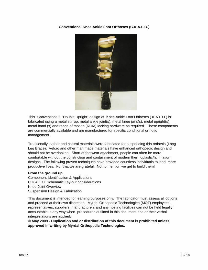
Conventional Knee Ankle Foot Orthoses (C.K.A.F.O.)
This "Conventional", "Double Upright" design of Knee Ankle Foot Orthoses ( K.A.F.O.) is fabricated using a metal stirrup, metal ankle joint(s), metal knee joint(s), metal upright(s), metal band (s) and range of motion (ROM) locking hardware as required. These components are commercially available and are manufactured for specific conditional orthotic management.
Traditionally leather and natural materials were fabricated for suspending this orthosis (Long Leg Brace). Velcro and other man made materials have enhanced orthopedic design and g ) p gshould not be overlooked. Short of footwear attachment, people can often be more comfortable without the constriction and containment of modern thermoplastic/lamination designs. The following proven techniques have provided countless individuals to lead more productive lives. For that we are grateful. Not to mention we get to build them!
From the ground up. Component Identification & Applications C.K.A.F.O. Schematic Lay-out considerations Knee Joint Overview Suspension Design & Fabrication
This document is intended for learning purposes only. The fabricator must assess all options and proceed at their own discretion. Myrdal Orthopedic Technologies (MOT) employees, representatives, suppliers, manufacturers and any hosting facilities can not be held legally accountable in any way when procedures outlined in this document and or their verbal interpretations are applied. © May 2009 - Duplication and or distribution of this document is prohibited unless approved in writing by Myrdal Orthopedic Technologies.
100611 1 of 18
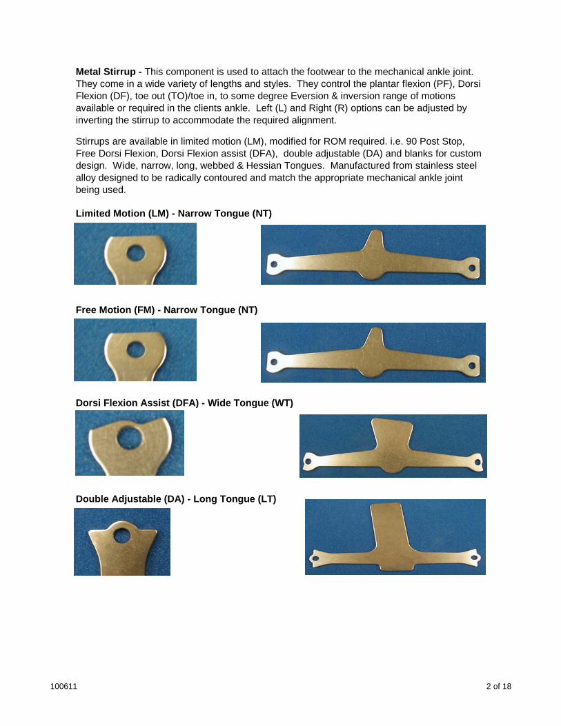
Metal Stirrup - This component is used to attach the footwear to the mechanical ankle joint. They come in a wide variety of lengths and styles. They control the plantar flexion (PF), Dorsi Flexion (DF), toe out (TO)/toe in, to some degree Eversion & inversion range of motions available or required in the clients ankle. Left (L) and Right (R) options can be adjusted by inverting the stirrup to accommodate the required alignment.
Stirrups are available in limited motion (LM), modified for ROM required. i.e. 90 Post Stop, Free Dorsi Flexion, Dorsi Flexion assist (DFA), double adjustable (DA) and blanks for custom design. Wide, narrow, long, webbed & Hessian Tongues. Manufactured from stainless steel alloy designed to be radically contoured and match the appropriate mechanical ankle joint being used.
Limited Motion (LM) - Narrow Tongue (NT)
Free Motion (FM) - Narrow Tongue (NT)
Dorsi Flexion Assist (DFA) - Wide Tongue (WT)Dorsi Flexion Assist (DFA) - Wide Tongue (WT)
Double Adjustable (DA) - Long Tongue (LT)
100611 2 of 18
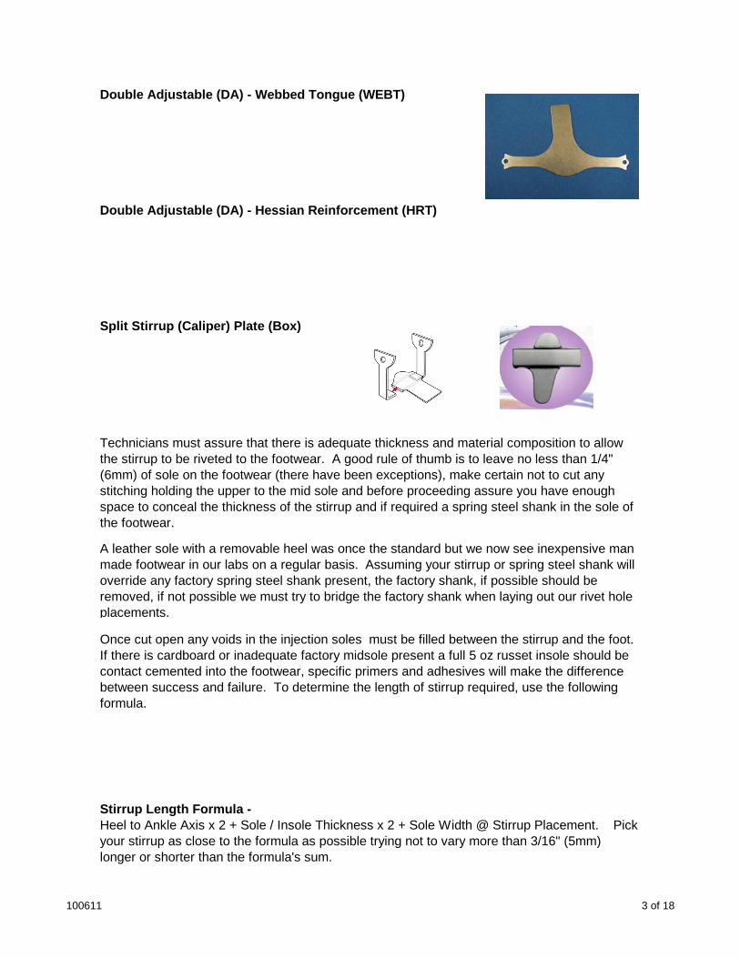
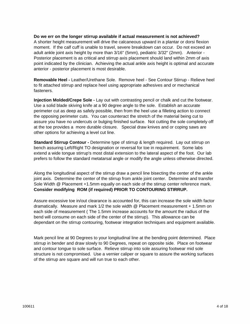
Double Adjustable (DA) - Webbed Tongue (WEBT)
Double Adjustable (DA) - Hessian Reinforcement (HRT)
Split Stirrup (Caliper) Plate (Box)
Technicians must assure that there is adequate thickness and material composition to allow the stirrup to be riveted to the footwear. A good rule of thumb is to leave no less than 1/4" (6mm) of sole on the footwear (there have been exceptions), make certain not to cut any stitching holding the upper to the mid sole and before proceeding assure you have enough space to conceal the thickness of the stirrup and if required a spring steel shank in the sole of the footwear.
A leather sole with a removable heel was once the standard but we now see inexpensive man made footwear in our labs on a regular basis. Assuming your stirrup or spring steel shank will override any factory spring steel shank present, the factory shank, if possible should be removed, if not possible we must try to bridge the factory shank when laying out our rivet hole placements.
Once cut open any voids in the injection soles must be filled between the stirrup and the foot. If there is cardboard or inadequate factory midsole present a full 5 oz russet insole should be contact cemented into the footwear, specific primers and adhesives will make the difference between success and failure. To determine the length of stirrup required, use the following formula.
Stirrup Length Formula - Heel to Ankle Axis x 2 + Sole / Insole Thickness x 2 + Sole Width @ Stirrup Placement. Pick your stirrup as close to the formula as possible trying not to vary more than 3/16" (5mm) longer or shorter than the formula's sum.
100611 3 of 18
Do we err on the longer stirrup available if actual measurement is not achieved? A shorter height measurement will drive the calcaneous upward in a plantar or dorsi flexion moment. If the calf cuff is unable to travel, severe breakdown can occur. Do not exceed an adult ankle joint axis height by more than 3/16" (5mm), pediatric 3/32" (2mm). Anterior - Posterior placement is as critical and stirrup axis placement should land within 2mm of axis point indicated by the clinician. Achieving the actual ankle axis height is optimal and accurate anterior - posterior placement is most desirable.
Removable Heel - Leather/Urethane Sole. Remove heel - See Contour Stirrup - Relieve heel to fit attached stirrup and replace heel using appropriate adhesives and or mechanical fasteners.
Injection Molded/Crepe Sole - Lay out with contrasting pencil or chalk and cut the footwear. Use a solid blade skiving knife at a 90 degree angle to the sole. Establish an accurate perimeter cut as deep as safely possible, then from the heel use a filleting action to connect the opposing perimeter cuts. You can counteract the stretch of the material being cut to assure you have no undercuts or bulging finished surface. Not cutting the sole completely off at the toe provides a more durable closure. Special draw knives and or coping saws are other options for achieving a level cut line.
Standard Stirrup Contour - Determine type of stirrup & length required. Lay out stirrup on bench assuring Left/Right TO designation or reversal for toe in requirement. Some labs extend a wide tongue stirrup's most distal extension to the lateral aspect of the foot. Our lab prefers to follow the standard metatarsal angle or modify the angle unless otherwise directed.
Along the longitudinal aspect of the stirrup draw a pencil line bisecting the center of the ankle joint axis. Determine the center of the stirrup from ankle joint center. Determine and transfer j p jSole Width @ Placement +1.5mm equally on each side of the stirrup center reference mark. Consider modifying ROM (if required) PRIOR TO CONTOURING STIRRUP.
Assure excessive toe in/out clearance is accounted for, this can increase the sole width factor dramatically. Measure and mark 1/2 the sole width @ Placement measurement + 1.5mm on each side of measurement ( The 1.5mm increase accounts for the amount the radius of the bend will consume on each side of the center of the stirrup). This allowance can be dependant on the stirrup contouring, footwear integration techniques and equipment available.
Mark pencil line at 90 Degrees to your longitudinal line at the bending point determined. Place stirrup in bender and draw slowly to 90 Degrees, repeat on opposite side. Place on footwear and contour tongue to sole surface. Relieve stirrup into sole assuring footwear mid sole structure is not compromised. Use a vernier caliper or square to assure the working surfaces of the stirrup are square and will run true to each other.
100611 4 of 18
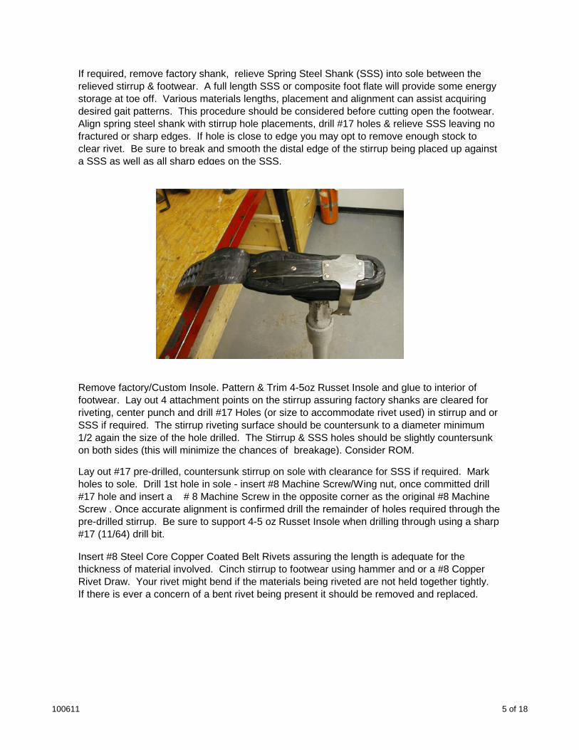
If required, remove factory shank, relieve Spring Steel Shank (SSS) into sole between the relieved stirrup & footwear. A full length SSS or composite foot flate will provide some energy storage at toe off. Various materials lengths, placement and alignment can assist acquiring desired gait patterns. This procedure should be considered before cutting open the footwear. Align spring steel shank with stirrup hole placements, drill #17 holes & relieve SSS leaving no fractured or sharp edges. If hole is close to edge you may opt to remove enough stock to clear rivet. Be sure to break and smooth the distal edge of the stirrup being placed up against a SSS as well as all sharp edges on the SSS.
Remove factory/Custom Insole. Pattern & Trim 4-5oz Russet Insole and glue to interior of footwear. Lay out 4 attachment points on the stirrup assuring factory shanks are cleared for riveting, center punch and drill #17 Holes (or size to accommodate rivet used) in stirrup and or g, p ( ) pSSS if required. The stirrup riveting surface should be countersunk to a diameter minimum 1/2 again the size of the hole drilled. The Stirrup & SSS holes should be slightly countersunk on both sides (this will minimize the chances of breakage). Consider ROM.
Lay out #17 pre-drilled, countersunk stirrup on sole with clearance for SSS if required. Mark holes to sole. Drill 1st hole in sole - insert #8 Machine Screw/Wing nut, once committed drill #17 hole and insert a # 8 Machine Screw in the opposite corner as the original #8 Machine Screw . Once accurate alignment is confirmed drill the remainder of holes required through the pre-drilled stirrup. Be sure to support 4-5 oz Russet Insole when drilling through using a sharp #17 (11/64) drill bit.
Insert #8 Steel Core Copper Coated Belt Rivets assuring the length is adequate for the thickness of material involved. Cinch stirrup to footwear using hammer and or a #8 Copper Rivet Draw. Your rivet might bend if the materials being riveted are not held together tightly. If there is ever a concern of a bent rivet being present it should be removed and replaced.
100611 5 of 18
Riveting - Once cinched trim rivet with enough excess to fill the countersink, one blow with the flat of a ball peen hammer should contain the rivet in the countersink, proceed to perimeter peaning & draw the stirrup into the sole when riveting. It is important to balance the compression of the stirrup to the footwear so move in opposing attachment points to balance the overall compression required to provide optimal stirrup alignment & secure attachment. Thicker or softer mid-soles will compress when riveting
Once even compression of the stirrup surface is accomplished the rivets should be set. This can be done with the flat of a ball pean hammer if the finished rivet is not exposed. If the finished rivet is exposed you may consider using a rivet set to provide a higher level of cosmesis and reduced sharp edge potential.
Footwear closure: Footwear & stirrup surfaces should be clean and free of dust, dirt oil and or grease. If present they should be sanded and or removed with compatible thinners. If used properly, specific primers and adhesives will accommodate the majority of footwear closure procedures. Our Lab uses a Renia product (Colle de Cologne) and its specific thinners in the majority of our challenging adhesion requirements. Consider Aquaseal.
Renia Urethane & Thermoplastic primers are available. An open "Aero Bar" structure found in cut soles often indicates a urethane injected sole, therefore a urethane primer is required.
A harder, gummy, plastic like surface of a cut or trimmed sole usually indicates a thermoplastic sole. Thermoplastic primers are available for these applications. Always read and follow the manufacturer's instructions and directions. We recommend reading them at least twice!
If an incompatible primer is used it can cause the material to decompose. If you are uncertain of the material you are adhering to, a small-scale test is recommended. Very difficult adhesionof the material you are adhering to, a small scale test is recommended. Very difficult adhesion situations can be addressed by priming a sole surface with cynacrolates (Crazy Glue) Once again a small scale test should be applied to assure the cynacrolates do not decompose the sole material. Allow Cyanoacrylate to dry for 1 - 2 hrs before applying contact cement.
Most contact cements take a minimum of 15 minutes to flash off and become ready for attachment. This will be effected by temperature and humidity. Try to avoid excessively cool/hot temperatures and or high humidity conditions. If high humidity is present you can force dry the surfaces using low temperature heat. Always follow the manufacturer's directions paying particular attention to the types of materials the adhesive has been designed for. The manufacturer should identify the recommended "open time" the adhesive requires to work effectively. Follow directions! Small scale testing is recommended if you are uncertain of the materials and or adhesives being used. Always be certain adequate make up air is available when using any chemical. Follow all safety procedures.
100611 6 of 18

Apply sole, raise and or modification - Trim to finish
100611 7 of 18
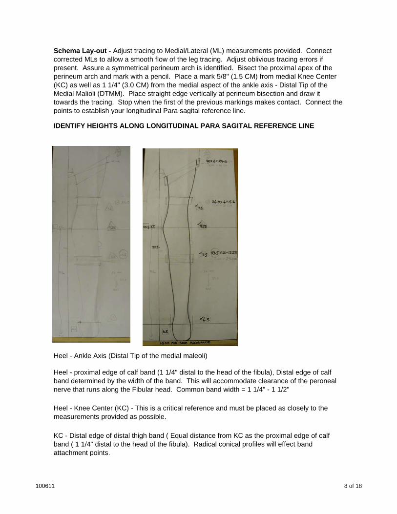
Schema Lay-out - Adjust tracing to Medial/Lateral (ML) measurements provided. Connect corrected MLs to allow a smooth flow of the leg tracing. Adjust oblivious tracing errors if present. Assure a symmetrical perineum arch is identified. Bisect the proximal apex of the perineum arch and mark with a pencil. Place a mark 5/8" (1.5 CM) from medial Knee Center (KC) as well as 1 1/4" (3.0 CM) from the medial aspect of the ankle axis - Distal Tip of the Medial Malioli (DTMM). Place straight edge vertically at perineum bisection and draw it towards the tracing. Stop when the first of the previous markings makes contact. Connect the points to establish your longitudinal Para sagital reference line.
IDENTIFY HEIGHTS ALONG LONGITUDINAL PARA SAGITAL REFERENCE LINE
Heel - Ankle Axis (Distal Tip of the medial maleoli)
Heel - proximal edge of calf band (1 1/4" distal to the head of the fibula), Distal edge of calf band determined by the width of the band. This will accommodate clearance of the peroneal nerve that runs along the Fibular head. Common band width = 1 1/4" - 1 1/2"
Heel - Knee Center (KC) - This is a critical reference and must be placed as closely to the measurements provided as possible.
KC - Distal edge of distal thigh band ( Equal distance from KC as the proximal edge of calf band ( 1 1/4" distal to the head of the fibula). Radical conical profiles will effect band attachment points.
100611 8 of 18

Maximum Medial Height = Heel - Medial measurement provided. Condition @ perineum will effect height. Critical Measurement! Leather work extension must be considered.
Maximum Lateral height = Heel - Lateral measurement provided (commonly 1" - 1 1/2 ") proximal to the medial structure height required. The proximal lateral upright length would be extended if a hip joint is incorporated into the design requirements.
IDENTIFY CUFF THICKNESS( Adjust if required) - LEAORTH = 1.5mm, PLASTIZOTE = 3mm, 5 oz Russet = 3mm, Band cover = 1.5mm , Billet = 1.0mm TOTAL = 10.0mm
Mark cuff thickness @ 10 mm parallel to structural members (calf, distal & proximal thigh band attachment points.) This reference line will represent the inside of the metal bands. Connect lines at contact points. Draw in metal band thickness reference lines.
DETERMINE BAND LENGTHS
Calf Band (Standard 2024 T3 Aluminum X 1/8" X 1 1/4" X Length Required) = Calf circumference x .65 (Oversized x 2-3%) - Cut upsized band as per length required, remove all sharp edges. This can be more easily accomplished prior to contouring the band. Excess length should be accounted for if radical conical leg profiles are present. (6061)
Distal Thigh Band (Standard 2024 T6 Aluminum X 1/8" X 1 1/4" X Length Required) = Distal Thigh circumference x .60 - Cut upsized band to length required, remove all sharp edges. This can be easily done prior to contouring the band. Excess length should be accounted for if radical conical leg profiles are present.
Proximal Thigh Band (Standard T6 Aluminum X 1/8" X 1 1/4" X Length Required) = Proximal Thigh circumference x .60 - Cut upsized band to length required ,remove all sharp edges. This can be easily done prior to contouring the band. Excess length should be accounted for if radical conical leg profiles are present.
100611 9 of 18
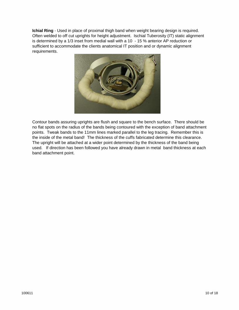
Ichial Ring - Used in place of proximal thigh band when weight bearing design is required. Often welded to off cut uprights for height adjustment. Ischial Tuberosity (IT) static alignment is determined by a 1/3 inset from medial wall with a 10 - 15 % anterior AP reduction or sufficient to accommodate the clients anatomical IT position and or dynamic alignment requirements.
Contour bands assuring uprights are flush and square to the bench surface. There should be no flat spots on the radius of the bands being contoured with the exception of band attachment points. Tweak bands to the 11mm lines marked parallel to the leg tracing. Remember this is the inside of the metal band! The thickness of the cuffs fabricated determine this clearance. The upright will be attached at a wider point determined by the thickness of the band being used. If direction has been followed you have already drawn in metal band thickness at each band attachment point.
100611 10 of 18
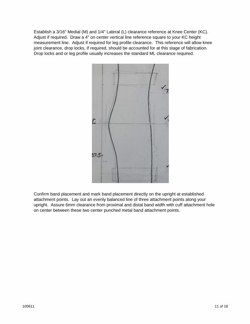
Establish a 3/16" Medial (M) and 1/4" Lateral (L) clearance reference at Knee Center (KC). Adjust if required. Draw a 4" on center vertical line reference square to your KC height measurement line. Adjust if required for leg profile clearance. This reference will allow knee joint clearance, drop locks, if required, should be accounted for at this stage of fabrication. Drop locks and or leg profile usually increases the standard ML clearance required.
Confirm band placement and mark band placement directly on the upright at established attachment points. Lay out an evenly balanced line of three attachment points along your upright. Assure 6mm clearance from proximal and distal band width with cuff attachment hole on center between these two center punched metal band attachment points.
100611 11 of 18
Knee Joints: There are a variety of knee joints available for KAFO fabrication. They are available with Stainless Steel (SS), Aluminum (Alum), Cast Aluminum & Titanium (TI) uprights. They are available in different upright widths and thickness to accommodate loads being applied by the client. The joint heads themselves are commonly manufactured using tool steels that have been hardened provide longevity and prevent premature wear. They are available with posterior offsets to improve knee stability, proximal and or distal contours to accommodate leg deformities such as excessive varus or Valgus conditions. Polycentric knee joints accommodate difficult knee center placements and reduce pistoning situations. Modular knee joints available, allow for easy change in circumstances such as wear and or offset adjustment requirements.
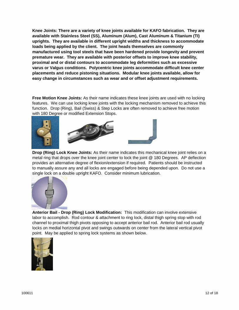
Free Motion Knee Joints: As their name indicates these knee joints are used with no locking features. We can use locking knee joints with the locking mechanism removed to achieve this function. Drop (Ring), Bail (Swiss) & Step Locks are often removed to achieve free motion with 180 Degree or modified Extension Stops.
Drop (Ring) Lock Knee Joints: As their name indicates this mechanical knee joint relies on a metal ring that drops over the knee joint center to lock the joint @ 180 Degrees. AP deflection provides an alternative degree of flexion/extension if required. Patients should be instructed to manually assure any and all locks are engaged before being depended upon. Do not use a single lock on a double upright KAFO Consider minimum lubricationsingle lock on a double upright KAFO. Consider minimum lubrication.
Anterior Bail - Drop (Ring) Lock Modification: This modification can involve extensive labor to accomplish. Rod contour & attachment to ring lock, distal thigh spring stop with rod channel to proximal thigh pivots opposing to accept anterior bail rod. Anterior bail rod usually locks on medial horizontal pivot and swings outwards on center from the lateral vertical pivot point. May be applied to spring lock systems as shown below.
100611 12 of 18
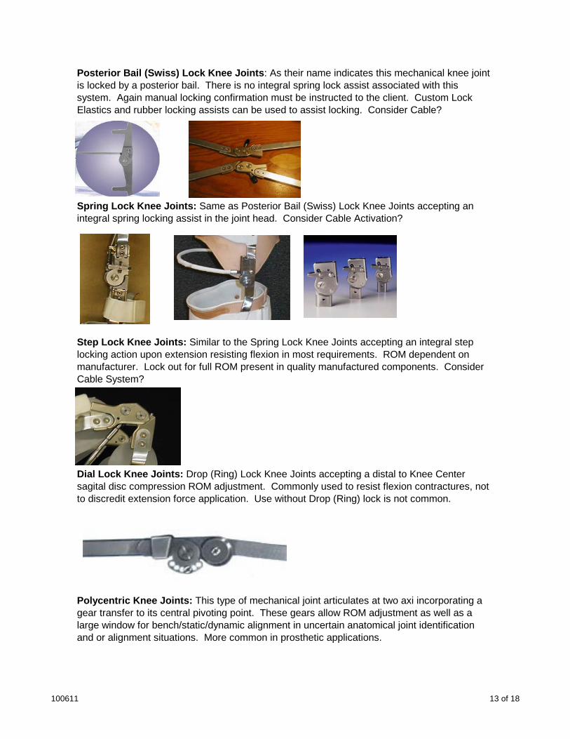
Posterior Bail (Swiss) Lock Knee Joints: As their name indicates this mechanical knee joint is locked by a posterior bail. There is no integral spring lock assist associated with this system. Again manual locking confirmation must be instructed to the client. Custom Lock Elastics and rubber locking assists can be used to assist locking. Consider Cable?
Spring Lock Knee Joints: Same as Posterior Bail (Swiss) Lock Knee Joints accepting an integral spring locking assist in the joint head. Consider Cable Activation?
Step Lock Knee Joints: Similar to the Spring Lock Knee Joints accepting an integral step locking action upon extension resisting flexion in most requirements. ROM dependent on manufacturer. Lock out for full ROM present in quality manufactured components. Consider Cable System?
Dial Lock Knee Joints: Drop (Ring) Lock Knee Joints accepting a distal to Knee Center sagital disc compression ROM adjustment. Commonly used to resist flexion contractures, not to discredit extension force application. Use without Drop (Ring) lock is not common.
Polycentric Knee Joints: This type of mechanical joint articulates at two axi incorporating a gear transfer to its central pivoting point. These gears allow ROM adjustment as well as a large window for bench/static/dynamic alignment in uncertain anatomical joint identification and or alignment situations. More common in prosthetic applications.
100611 13 of 18

Any Anterior or Posterior (AP) Deflections to account for flexion or extension requirements should be performed before any Medial or Lateral (ML) contours are implemented. Uprights should be deflected equal in degrees of flexion and or extension. Consider equal proximal and distal deflections when required. An uncommon exception is when Tibial torsion is accounted for. This process deflects the lateral upright posteriorly distal to the calf band the distance prescribed to offset the attachment point at the lateral ankle axis.
Free hand contour uprights to the reference lines established. Remember to allow for the metal band thickness at upright attachment points. On average the upright will be 3mm wider than the 10mm cuff thickness reference, or 13mm from the adjusted ML measurement. Keep the knee joint and uprights at 90 degrees to the schematic (bench surface). This should assure that the 90 degree band contour at attachment does not overly distort your final alignment.
Confirm and mark band height measurements and Drill a # 29 hole at each band/cuff attachment point (3 hole series). Deburr all holes drilled. A # 29 (9/64") drill bit is used for #10attachment point (3 hole series). Deburr all holes drilled. A # 29 (9/64 ) drill bit is used for #10 or 1/8" diameter rivets. If a trial fit is required drill only the center hole in each three hole series laid out and center punched on the uprights ( use mild or no center punch at points not being drilled).
Assure attachment points are accurate and clamp bands to upright(s) consider using 6" offset grip clamps that have been modified so they do not mar the surfaces being clamped. The angle allows the technician to fix band attachment points from the posterior aspect of the orthoses. Some labs use c clamps and or aircraft riveting alignment devices for this process.
If excessive conical leg profiles are present consider drilling single attachment point furthest from KC for trial fitting. Attachment closest to KC an be applied if a negative leg profile is present.
For trial fitting, the calf band should be tilted if a severe conical shape is present. Leaving a distal attachment only (unless distal circumference at band attachment is larger than proximal) will allow for maximum adjustment. Aligning the inner posterior angles of the proximal and distal thigh bands is recommended for trial fitting. Leaving a proximal attachment only will allow for maximum adjustment (Negative proximal circumferences in the thigh are uncommon). Any adjustments required can be made once the orthoses has been trial fit and assessed for required function.
100611 14 of 18
If no major variances are present use the center hole to mount the metal bands (cuff attachment point) for trial fitting. This choice also allows for maximum adjustment, tilting, raising or lowering the band. With clamps in place drill holes and replace with 6-32 Flat head machine screws and nuts as you proceed. Burrs (Leather or Metal) can be used to reduce upright damage from the machine screws.
Assemble CKAFO Structure - TRIAL
Assure Heel - Ankle joint Axis measurement on finished stirrup placement is accurate and recorded on measurement form. Adjust if required mark ankle joint placement and cut upright length to trial fit. Drill distal attachment point only and attach with a round head 6-32 SS Machine Screw. Be sure to cut, grind and tape all machine screw attachments for trial fitting.
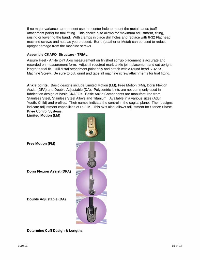
Ankle Joints: Basic designs include Limited Motion (LM), Free Motion (FM), Dorsi Flexion Assist (DFA) and Double Adjustable (DA). Polycentric joints are not commonly used in fabrication design of basic CKAFOs. Basic Ankle Components are manufactured from Stainless Steel, Stainless Steel Alloys and Titanium. Available in a various sizes (Adult, Youth, Child) and profiles. Their names indicate the control in the sagital plane. Their designs indicate adjustment capabilities of R.O.M. This axis also allows adjustment for Stance Phase Knee Control Systems. Limited Motion (LM)
Free Motion (FM)ee ot o ( )
Dorsi Flexion Assist (DFA)
Double Adjustable (DA)
Determine Cuff Design & Lengths
100611 15 of 18
Conical and or stove pipe leg shape profiles present when designing your cuff pattern? A straight cuff layout will accommodate stove pipe profiles. The aspects of the cuff anterior from the edge of the upright at band attachment point will need to be angled distally if there is a conical profile present. The angle will need to be reduced proximally if the distal circumference is larger than the proximal at cuff attachment point.
The band angles present in the KAFO structure will determine the angles required to provide a custom fit. If radical conical profiles are present band angle placement must be accounted for. Trial fitting radical profile KAFOs is recommended.
Calf Cuff = 2-3 oz pearled white cow lining (3 7/8" wide x length)/3mm Plastizote (2 1/8" x length of band + 1") / 5oz Russet x length)/Dacron Hook & Loop Closure (Loop = upright edge to loop Hook = 1" less than loop unless 4" minimal length is not attainable). Assume band = 1 1/4" If circumference measurement is over 16" add 2 1/2" (6 CM) for finished cuff length. If measurement is under 16" add 1 1/2" (4 CM) and or assure adequate overlap is accounted for. Options: Duraflex, Rollover, Offset, Corset, Half cuff, Sling, None, Other
Distal Thigh Cuff = 2-3 oz pearled white cow lining (3 7/8" wide x length)/3mm Plastizote (2 1/8" x length)/5oz Russet (2" x length)/Dacron Hook & Loop Closure (Loop = upright edge to loop Hook = 1" less than loop unless 4" minimal length is not attainable). Assume band = 1 1/4" If circumference measurement is over 16" add 2 1/2" for finished cuff length. If measurement is under 16" add 1 1/2" and or assure adequate overlap is accounted for. Options: Duraflex, Rollover, Offset, Corset, Half cuff, Sling, Other
Proximal Thigh Cuff = LEAORTH/3MMPZOTE/5OZRUSSET/H&LCLOSURE Options: Duraflex, Rollover, Offset, Corset, Half cuff, Sling, Other. If circumference measurement is over 16" add 2 1/2" for finished cuff length. If measurement is under 16" add 1 1/2" and or gassure adequate overlap is accounted for.
Roll Over Cuff - These cuffs have an extension proximally and or distally that provide extra padding and transition comfort of the band and cuff combination. The cuff structure pattern is standard but the padding and liner is extended to "Roll Over" the edge of the band requiring extra padding/transition function. The liner proximal band edge aspect and padding is left open and is skived so it can be inverted and attached to the outer surface of the cuff.
Other Cuff Options - Half cuff covers only the metal band. Sling Cuff is used in place of a band and is free floating with acceptation of upright attachment points. The above cuffs are traditionally fabricated using leather but there are many man made material options available such as Duraflex, Dacron, Nylon, Vinyl etc.
Consider Hybrid designs. You may use a conventional proximal section and a thermoplastic distal section or the opposite configuration. These design options give our clients the variety they may require to improve their quality of life.
100611 16 of 18
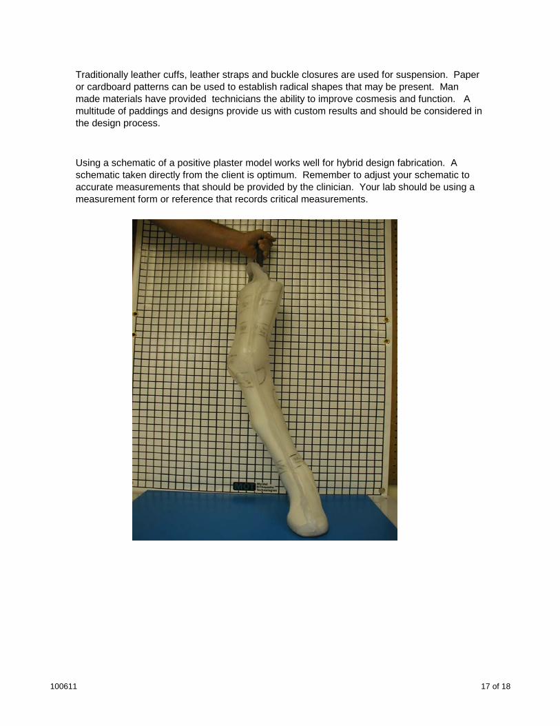
Traditionally leather cuffs, leather straps and buckle closures are used for suspension. Paper or cardboard patterns can be used to establish radical shapes that may be present. Man made materials have provided technicians the ability to improve cosmesis and function. A multitude of paddings and designs provide us with custom results and should be considered in the design process.
Using a schematic of a positive plaster model works well for hybrid design fabrication. A schematic taken directly from the client is optimum. Remember to adjust your schematic to accurate measurements that should be provided by the clinician. Your lab should be using a measurement form or reference that records critical measurements.
100611 17 of 18
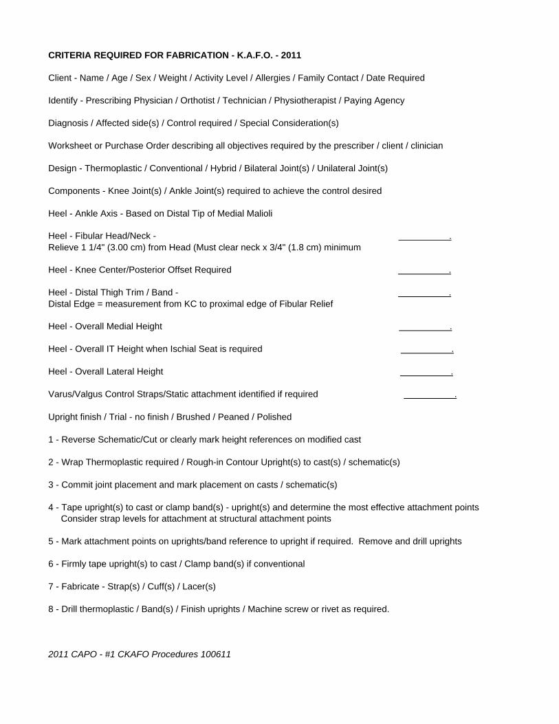
CRITERIA REQUIRED FOR FABRICATION - K.A.F.O. - 2011
Client - Name / Age / Sex / Weight / Activity Level / Allergies / Family Contact / Date Required
Identify - Prescribing Physician / Orthotist / Technician / Physiotherapist / Paying Agency
Diagnosis / Affected side(s) / Control required / Special Consideration(s)
Worksheet or Purchase Order describing all objectives required by the prescriber / client / clinician
Design - Thermoplastic / Conventional / Hybrid / Bilateral Joint(s) / Unilateral Joint(s)
Components - Knee Joint(s) / Ankle Joint(s) required to achieve the control desired
Heel - Ankle Axis - Based on Distal Tip of Medial Malioli
Heel - Fibular Head/Neck - .Relieve 1 1/4" (3.00 cm) from Head (Must clear neck x 3/4" (1.8 cm) minimum
Heel - Knee Center/Posterior Offset Required .
Heel - Distal Thigh Trim / Band - .Distal Edge = measurement from KC to proximal edge of Fibular Relief
Heel - Overall Medial Height .
Heel - Overall IT Height when Ischial Seat is required .
Heel - Overall Lateral Height .
Varus/Valgus Control Straps/Static attachment identified if required .
Upright finish / Trial - no finish / Brushed / Peaned / Polished
1 - Reverse Schematic/Cut or clearly mark height references on modified cast
2 - Wrap Thermoplastic required / Rough-in Contour Upright(s) to cast(s) / schematic(s)
3 - Commit joint placement and mark placement on casts / schematic(s)
4 - Tape upright(s) to cast or clamp band(s) - upright(s) and determine the most effective attachment points Consider strap levels for attachment at structural attachment points
5 - Mark attachment points on uprights/band reference to upright if required. Remove and drill uprights
6 - Firmly tape upright(s) to cast / Clamp band(s) if conventional
7 - Fabricate - Strap(s) / Cuff(s) / Lacer(s)
8 - Drill thermoplastic / Band(s) / Finish uprights / Machine screw or rivet as required.
2011 CAPO - #1 CKAFO Procedures 100611