conventional pid and modified pid controller design for ... · f. alarçin et al. conventional pid...
TRANSCRIPT
Acta Polytechnica Hungarica Vol. 11, No. 3, 2014
– 233 –
Conventional PID and Modified PID Controller
Design for Roll Fin Electro-Hydraulic Actuator
Fuat Alarçin1, Hakan Demirel
2, M. Ertugrul Su
1, Ahmet
Yurtseven1
1 Faculty of Naval Architecture and Maritime, Yıldız Technical University,
Barbaros Bulvari 34349 Beşiktaş İstanbul, Turkey
E-mail: [email protected], [email protected], [email protected]
2 Department of Marine Engineering Operations, Bulent Ecevit University, 67300
Ereğli/Zonguldak, Turkey
E-mail: [email protected]
Abstract: The aim of this study is to decrease a fishing boat’s roll motion, which is
adversely affected by disturbing hydrodynamic forces, by applying fin roll stabilizer. It is
ensured that roll motion with nonlinear damping and restoring moment coefficients reaches
the desired level by means of classical PID and modified PID algorithms. By Lyapunov’s
direct method, the key issue- stability which is needed during the course of sailing was
examined considering initial conditions, and it was realized that the system was generally
stable. Besides, NACA 0015 model was utilized for the fin roll stabilizer, and flow analysis
was conducted by CFD method. According to the simulation results, when the same gains
were practiced, modified PID controller algorithms were rather more efficient than
conventional PID in the roll fin stabilizer system.
Keywords: modified PID control; fin stabilizer; Lyapunov direct method
1 Introduction
For many years, vessels have remained as a research subject for researchers as
they lack fundamentals of stability despite meeting the requirements of current
laws. It is known that a ship on route is likely to be off the stable zone due to
disrupting hydrodynamic forces of a ship roll motion. Grim [1] modelled the roll
equation using the gradual change in the restoring moment among the waves. In
another study of his, he analyzed unstable roll equation in a more general equation
form using Mathieu equation.
F. Alarçin et al. Conventional PID and Modified PID Controller Design for Roll Fin Electro-Hydraulic Actuator
– 234 –
Advanced studies on roll motion were carried out by Dalzell [2], and alternative
damping models were put forward. Soliman and Thomson [3] solved the nonlinear
differential equation of roll motion through 4th
level Runga-Kutta method. How
damping effect of roll motion stability changed owing to disrupting forces and
frequency was studied. Haddara and Wang [4] pointed out that quadratic damping
model of speed for small fishing ships came up with good results. Taylan [5]
studied a nonlinear roll motion model and the solution of this model through
generalized Krylov-Bogoliubov asymptotic method on a time line. In this model,
nonlinear restoring terms were considered as a 3rd
level polonium; likewise,
nonlinear damping was regarded as a 2nd
level term. Taylan [6] studied on
generalization of the nonlinear equation form indicating roll motion of a ship
sailing amidst waves by means of Duffing method on frequency level. Surendran
and Reddy [7] discussed the roll dynamics of a Ro-Ro ship taking into account
many types of combination of loads in linear and nonlinear forms.
Safety of voyage has to be assured against the disrupting hydrodynamic effects of
passengers as well as cargos, and roll amplitude has to be at an acceptable level.
Therefore, a number of applications such as fin roll stabilizers and U-tube have
been used in literature [8, 9].
Sgoppo and Persons [10] demonstrated that roll motion can be reduced by 35%
through fin roll stabilizer system based on WMEC 901 class ship with 3rd
degree
of freedom model. Surendran et al. [11] pointed out that nonlinear roll motion
could be minimized with the fin roll stabilizer based on PID (Proportional-
Integral-Derivative) control algorithm considering a frigate warship. In this study,
he acquired lift characteristics of the fin roll stabilizer stemming from
hydrodynamic flow using CFD (Computational Fluid Dynamics). In simulations
for different occasions, an 80% reduction in roll value was observed.
Guan and Zhang [12], who expressed nonlinear damping terms with the
Backstepping Integrator theory, controlled the nonlinear fin roll stabilizer by
means of PID and close loop algorithms by ignoring high level nonlinear terms.
Ghassemiet al. [13] expressed that fin roll stabilizers are effective components in
reducing roll amplitude out of wave movements. It was pointed out that lift forces
occurring around the angle of attack and the fin roll stabilizer create a reversed
moment. That’s why he showed roll amplitude could be reduced using PID and
Neural Network combination to control attack angle. Karakaş et al. [14] designed
a controller based on Lyapunov method for fin roll damping systems in beam seas.
The roll motion of the ship was considered as a single degree of freedom and 3rd
degree nonlinear terms were added to the model. It was mentioned that the
likelihood of capsize was reduced to a considerable extent by means of the
controller based on Lyapunov method. PID controllers’ versions have been
investigated by many researchers Alfaro et al. [24], Precup et al. [25], Hadlovska
and Jajcisin [26].

Acta Polytechnica Hungarica Vol. 11, No. 3, 2014
– 235 –
In this paper, the problem of a nonlinear roll motion of fishing vessel is
considered. Section 2 deals with mathematical model of nonlinear roll motion.
Section 3 analyses stability of roll motion by Lyapunov’s Direct Method. Section
4 describes the fin roll stabilizer system and classical PID and the modified PID
controller. Nonlinear roll motion of a fishing boat, which will be capable of
operating in the Black Sea and the Mediterranean Sea, was controlled by fin
stabilizer system. Section 5 discusses simulation results.
2 Mathematical Model of Nonlinear Roll Motion
In order to ease to design mathematical model of ship motions, some important
assumptions are made in modelling a fishing boat rolling motion, neglecting all
other degrees of freedom of ships, xz-plane symmetry, rigid body and
homogenous mass distribution. Considering some simplifications, the following
nonlinear expression for the roll equation is obtained,
3 5 2
1 2 1 3 5 e m e f(I+J) +B +B | | + ( c +c +c ) = I cos( t ) M (1)
where , , are angle, angular velocity and angular acceleration of roll motion,
respectively. I and J are the mass moment of inertia and the added mass moment
of inertia, respectively. 1 2B ,B are roll damping coefficients, 321 c,c,c are
determined by restoring force coefficients and is the weight displacement of
the ship, e is encounter frequency of the wave, m is the maximum wave slope,
fM is the control moment of active fins. Dividing the equation (1) throughout by
)JI( ,
2
3 5 e m e F
1 2 1 3 5
I cos( t ) M +b +b | |+ (c +c +c )=
I J I J
(2)
Inertia moment arises due to the ship’s reaction to a movement and it is
proportional to the acceleration of motion. Added inertia moment is a reaction of
sea water to the ship motion. These inertia values can be calculated depending on
weight displacement of ship ( ), breadth (B) and the vertical distance of the
center of gravity (KG),
)KG4B(g12
J)+(I 22
(3)
The roll damping coefficient for a ship hull form has several contributions. These
components are considered as skin friction of the hull, eddy shedding from the
hull, free surface waves, lift effect damping and bilge keel damping. Theoretical
and semi-empirical methods have been used to evaluate the roll damping by Ikeda

F. Alarçin et al. Conventional PID and Modified PID Controller Design for Roll Fin Electro-Hydraulic Actuator
– 236 –
et al. [15] and Ikeda [16]. A non-dimensional damping coefficient for different
ship types is expressed as follows:
GM)JI(a2B1
(4)
)JI(b4
3B2 (5)
These coefficients are directly related to a linear damping coefficient 1B and a
non-linear damping coefficient, 2B represents quadratic drag [2]. The non-
dimensional damping coefficients for fishing boat were obtained as follow (a=0.1,
b=0.0140). The curve for righting arm has been represented by the polynomial,
3 5
1 3 5M ( ) c c c ...
where 0c,0c,0c 531 . The roll restoring moment coefficients are defined
by ref. [6]
GMd
)GZ(dc1
)GMA3(4
c 2vv4
v
3
)GMA4(3
c 2vv6
v
5
(6)
Angle of vanishing stability v , area under the GZ curve vA , and dynamic
characteristics of the GZ curve such as metacentric height GM. Based on the
above-mentioned coefficients, numerical calculations were carried out for a
fishing boat, whose body plan is given in Fig. 1.
Figure 1
Body plan of the fishing boat
The righting arm curve is a graphical representation of the fishing boat’s stability
in Fig. 2 [17]. From this figure, it can be seen that Hydrodynamic lift effect
develops in an approximately linear manner with an increasing angle of attack.
roll
G
M
G
Z
φ
K

Acta Polytechnica Hungarica Vol. 11, No. 3, 2014
– 237 –
The area under the curve is an indication of the fishing boat’s ability to counter the
capsizing moments acting on the boat.
Figure 2
Righting arm curve of fishing boat
Due to the influences of high wave frequency, ships sailing on the sea produce
undesirable roll motion. It is expressed the wave moment to consist of the
encounter frequency as,
)t(cosIM em2ew (7)
)(cosVg
w
2w
we
wM is the wave moment, e is the encounter frequency of the wave, w is the
wave frequency, m is the maximum wave slope, w is the wave encounter
angle of the ship. It can be envisaged that the wave excitation will depend not only
on amplitude and frequency of the waves but also on encounter angle and speed.
3 Stability Analysis of Roll Motion by Lyapunov’s
Direct Method
A fishing boat is called stable when it has enough positive stability to counter the
external forces generated by current weather, fishing conditions and it will return
to its upright position [18]. Lyapunov’s Direct Method was used for stability
analyses by Ozkan [19]. This is a very powerful and applicable technique since it

F. Alarçin et al. Conventional PID and Modified PID Controller Design for Roll Fin Electro-Hydraulic Actuator
– 238 –
does not require any knowledge about the explicit solutions of the equations. By
using state variables of equation (1),
1 2
2 3 5
2 0 1 3 1 5 1 1 2 2 2 2( m m ) (b b ) (8)
Lyapunov function xV satisfying
0Vx positive definite and 0(0)V
0dt
)xdV(
V(x) as x
Lyapunov second method will be used to test the system stability.
If symmetric coefficients are assumed equal to zero, derivative of the Lyapunov
function is negative. Lyapunov function is obtained depending on the non-linear
roll damping coefficient. If this value is smaller than zero, non-linear roll motion
can be said to be stable.
2
2 1 2 2 0V ( x ) (b b ) (9)
2 4 6
2 1 1 1
0 3 52 4 6
V( x ) m m
(10)
4 Controller Design for Roll Fin Actuator
The objective of the control is to generate the input current such that the angular
position of the control fin is regulated to the desired position. The motion of a ship
can be affected by fin actuators that impart forces and moments. Actuators play a
very important role in the control system structure. When the roll fin stabilizers
attack to the fluid, it can bee seen that the lifting force caused by the rotation and
the angle of attack occurs on the surface of fins. The lift force and the lift in non-
dimensional form are as in the following form in Fig. 3 [8],
xVdt
)xdV((t)V T

Acta Polytechnica Hungarica Vol. 11, No. 3, 2014
– 239 –
Figure 3
Ship roll fin stabilizer
LFCAV2
1L (11)
F2LAV5.0
LC
(12)
where L lifting force (N); density of fluid (t/m3); FA fins area (m
2); LC fins
lift coefficient (lift coefficient/rad); V the ship speed (m/s). General formulas of
fin roll stabilizer are expressed as the following equations:
2
F F L F F FM V A C I ( I )v
(13)
whereFM , fin roll stabilizer moment;
FI the fins force arm; F attack angle. The
electro-hydraulic system dynamics of fin stabilizer system are assumed to be
governed by
F2F1F utt (14)
where F is the actuator output (actual fin angle), u is the input to the electro-
hydraulic systems. The hydraulic control model presented in Fig. 4. Conrol
surfaces are commanded by hydraulic machinery that implement the action
demanded by controller.
Figure 4
Block diagram of fin stabilizer system
As can be seen in Fig. 4, a saturator has been intermitted between the controller
and the fin actuator.
Out1
1
Saturation 1Saturation Integrator
1
s
t1
Gain 6
t2
In1
1
αF uF
fy
fx U
f
ı
fx
F. Alarçin et al. Conventional PID and Modified PID Controller Design for Roll Fin Electro-Hydraulic Actuator
– 240 –
This element models the saturating behaviour of the controller. The foil motion is
constrained to move within certain maximum angle.
F max F F max
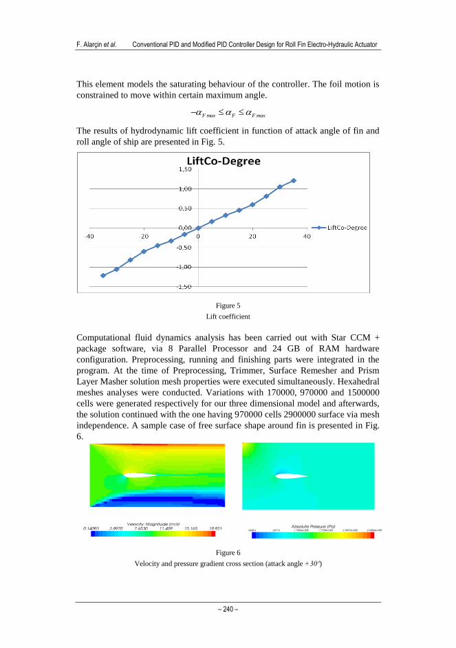
The results of hydrodynamic lift coefficient in function of attack angle of fin and
roll angle of ship are presented in Fig. 5.
Figure 5
Lift coefficient
Computational fluid dynamics analysis has been carried out with Star CCM +
package software, via 8 Parallel Processor and 24 GB of RAM hardware
configuration. Preprocessing, running and finishing parts were integrated in the
program. At the time of Preprocessing, Trimmer, Surface Remesher and Prism
Layer Masher solution mesh properties were executed simultaneously. Hexahedral
meshes analyses were conducted. Variations with 170000, 970000 and 1500000
cells were generated respectively for our three dimensional model and afterwards,
the solution continued with the one having 970000 cells 2900000 surface via mesh
independence. A sample case of free surface shape around fin is presented in Fig.
6.
Figure 6
Velocity and pressure gradient cross section (attack angle +30º)

Acta Polytechnica Hungarica Vol. 11, No. 3, 2014
– 241 –
We considered only a magnitude constraint for the mechanical angle of the fins as
30°. Segregated flow, Reynolds averaged Navier Stokes and k-ε turbulence model
were used as the solvers for running process. Convergence conditions were
approximately 1E-5 ( 510 ). Running was carried out in parallel with 8 cores.
During the final process, along with the velocity and pressure gradients, the lift
force coefficient was directly taken from the model. This coefficient was obtained
depending on fin roll stabilizer’s attack angle (from -30º to +30º).
4.1 Conventional PID Controller
The parameters of PID controller lead to different effects on system
characteristics. The proportional block provides an overall control action, and the
integral block reduces steady-state errors. On the other hand, the derivative block
improves transient response. The basic elements of a PID controller for a ship roll
motion control system are shown in Fig. 7 [20].
Figure 7
Closed loop system with conventional PID controller
Generally, transfer function of classical PID controller is given below:
dt
)t(de)t(d
1eK)t(G d
ippid
(15)
Wherep
dd
i
p
iK
K,
K
K and e is the error between the reference and the output
of a system, i is the integral time, d is derivative time. ip K,K and dK are
P
I
D
+
+ +
Gs +
-
Conventional PID

F. Alarçin et al. Conventional PID and Modified PID Controller Design for Roll Fin Electro-Hydraulic Actuator
– 242 –
proportional, integral and derivative gains, respectively. The conventional PID
controller is the simplest form of controllers that utilize the derivative and
integration operations in the compensation of control systems. Thanks to its
flexibility, it is easier to use this controller in many applications and many control
problems [21, 22, 23, 24, 25, 26, 27 and 28]. The model of closed loop system
with modified PID is shown in Fig. 8.
4.2 Modified PID Controller
The position of integral action which affects the difference of reference signal and
feedback signal has remained unchanged on forward path. However, derivative
and proportional actions have moved on feedback path to affect only the output
signal. The objective is to force the system’s output to follow a given bounded
reference value.
Figure 8
The model of closed loop system with modified PID controller
The modified PID controller can be indicated as follows:
s
KssKK)s(G
d2
pi
c
(16)
Transfer function of closed loop system is given below:
KKK)KKKab(s)ba(ss
KK
)s(R
)s(C
pidi23
i
(17)
There are two zeros in the system with conventional PID controller. It is hard to
adjust the system response due to these zeros. Their effect occurs as earlier peak
or higher overshoot. The proposed modified PID controller gets over these effects
and ameliorates the system response by adding proportional and derivative blocks
of PID on feedback path instead of on forward path. Therefore, better solution of
system response is achieved in modified PID in comparison with conventional
PID.
Acta Polytechnica Hungarica Vol. 11, No. 3, 2014
– 243 –
5 Simulation
In control application, mathematical model was presented to perform numerical
simulations of different scenarios, and to obtain the performance of the fin
stabilizer system. These numerical simulations were applied with Matlab simulink
program. The fishing boat and the fin (NACA 0015) particulars are shown in
Table 1.
Table 1
The fishing boat and the fin (NACA 0015) particulars
Principal Particulars Symbol Parameter
Length between perpendiculars Lbp 20 m
Breadth B 5.714 m
Depth D 3.2 m
Draught T 2.285 m
Displacement 119.34 m3
Metacentric height GM 0.57 m
Vertical center of gravity KG 2.4 m
Block coefficient CB 0.457
Service speed V 10 knot
Fins area AF 2.5 m2
Fins lift coefficient CL 0.65
Vanishing angle of stability v 580
Non-dimensional damping and restoring moment coefficients for fishing boat are
expressed in Table 2.
Table 2
Non-dimensional damping and restoring moment coefficients for fishing boat
b1 b2 m1 m3 m5
0.069 0.010 1.204 -1.80 0.61
The flow chart of MPID control system is displayed in Fig. 8. The simulation
results for fin roll stabilizer system show roll angle, roll velocity and phase
diagram in Figs. 9, 10 and 11. Comparisons of the control performance were made
between conventional PID and the MPID controllers. Kp, Ki and Kd control values
were obtained by trial method. The values of PID gains Kp = 0.2145, Kd = 1.2288,
Ki =2.89, ensured good roll reduction. The modified PID control response of the
fin roll stabilizer is better than PID control.

F. Alarçin et al. Conventional PID and Modified PID Controller Design for Roll Fin Electro-Hydraulic Actuator
– 244 –
0 5 10 15 20 25 30 35-8
-6
-4
-2
0
2
4
6
8
Time (sec.)
Roll
angle
(deg.)
Uncontrolled
PID
MPID
Figure 9
Comparison of roll angle response
0 5 10 15 20 25 30 35-0.8
-0.6
-0.4
-0.2
0
0.2
0.4
0.6
0.8
Time (sec.)
Roll
velo
city (
deg./
sec.)
Uncontrolled
PID
MPID
Figure 10
Comparison of roll velocity response

Acta Polytechnica Hungarica Vol. 11, No. 3, 2014
– 245 –
-4 -3 -2 -1 0 1 2 3-0.8
-0.6
-0.4
-0.2
0
0.2
0.4
0.6
0.8
Roll angle (deg)
Roll
velo
city (
deg/s
ec)
Uncontrolled
PID
MPID
Figure 11
Comparison of phase diagram
10-2
10-1
100
-50
-40
-30
-20
-10
0
10
20
30
40
frequency (Hz)
Gain
dB
kontr
olc
ülü
Bode Plot
Uncontrolled
PID
MPID
Figure 12
Frequency response of the roll motion for uncontrolled, PID and MPID
Since the aim of the controller was to control the roll motion, the improvement has
been realized particularly around 1.1 Hz at low frequencies. This is also
demonstrated by plotting the frequency response of controlled and uncontrolled
body bounce acceleration in Fig. 12.
The comparison of the two controllers is presented in Table 3, which shows roll
angle and roll velocity. The settling time for uncontrolled is longer compared to
the time for settlement of MPID.
Frequency (Hz)
Gai
n (
dB
)

F. Alarçin et al. Conventional PID and Modified PID Controller Design for Roll Fin Electro-Hydraulic Actuator
– 246 –
Table 3
Performance Comparisons
Controller Max. roll angle (deg.) Max. roll velocity (deg./s)
Uncontrolled 7.80 0.7
PID 1.90 0.6
MPID 0.70 0.1
Conclusions
This paper introduces a mathematical modeling, and examines controlling of
nonlinear roll motion by applying fin stabilizer system. Nonlinear restoring and
damping moment coefficients are computed by means of empirical equations.
Nonlinear roll motion stability of fishing boat is examined through Lyapunov
direct method. In the course of the simulation, it is accepted that the control gains
receive the same values for PID and MPID algorithms. According to the results of
the simulation, it is notable that MPID controller has shown a considerable
amelioration in roll magnitude about 91%. The performance of MPID controller
performance has been 15.4% greater than conventional PID as shown in Table 3.
References
[1] O. Grim: schwingungen, Stabilitat und Sicherheit in Seegang,
Schiffstechnik (1952) pp. 85-100
[2] J. F. Dalzell: A Note on the Form of Ship Roll Damping, Journal of Ship
Research, Vol. 22(3) (1978) pp. 178-185
[3] M. Soliman and J. M. T. Thompson: Transient and Steady State Analysis of
Capsize Phenomena, Applied Ocean Research, 13 (1991) pp. 82-92
[4] M. Haddara and Y. Wang: Parametric Identification of Maneuvering
Models for Ships, Int. Shipbuild. Programs, 445 (1999) pp. 5-27
[5] M. Taylan: Solution of the Nonlinear Roll Model by a Generalized
Asymptotic Method, Ocean Engineering, Vol. 26 (1999) pp. 1169-1181
[6] M. Taylan: The Effect of Nonlinear Damping and Restoring in Ship
Rolling, Ocean Engineering, Vol. 27 (2000) pp. 921-932
[7] S. Surendran and R., Venkata Ramana Reddy: Roll Dynamics of a Ro-Ro
Ship, International Ship Building Progress, Vol. 49, No. 4 (2002) pp. 301-
320
[8] T. Perez and G. C. Goodwin: Constrained predictive Control of Ship Fin
Stabilizers to Prevent Dynamic Stall, Control Engineering Practice 16,
(2008) pp. 482-494
[9] C. Holden and T. I. Fossen: A Nonlinear 7-DOF Model for U-Tanks of
Arbitrary Shape, Ocean Engineering 45 (2012) pp. 22-37
Acta Polytechnica Hungarica Vol. 11, No. 3, 2014
– 247 –
[10] J. N. Sgobbo and M. Parsons: Rudder/Fin Roll Stabilization of the USCG
WMEC 901 Class Vessel, Marine Technology, 36 (1999) pp. 157-170
[11] S. Surendran, S. K. Lee and S. Y. Kim: Studies on an Algorithm to Control
the Roll Motion Using Active Fins, Ocean Engineering 34 (2007) pp. 542-
551
[12] W. Guan and X. K. Zhang: Concise Robust Fin Roll Stabilizer Design
Based on Integrator Backstepping and CGSA, Systems and Control in
Aeronautics and Astronautics (ISSCAA) 2010 3rd
International Symposium
on , Vol. 3, 8-10 June 2010, pp. 1392-1397
[13] H. Ghassemi, F. H. Dadmarzi, P.Ghadimi and B. Ommani: Neural
Network-PID Controller for Roll Fin Stabilizer. Polish Maritime Research
2(65) Vol. 17, (2010) pp. 21-30
[14] Ş. C. Karakas, E. Uçer and E. Pesman: Control Design of Fin Roll
Stabilization in Beam Seas Based on Lyapunov’s Direct Method, Polish
Maritime Research 2 (73), Vol. 19 (2012) pp. 25-30
[15] Y. Ikeda, Y. Himeno and N. Tanaka: New York A Prediction Method for
Ship Roll Damping, Report No. 00405 of the Department of Naval
Architecture, University of Osaka Prefecture (1978)
[16] Y. Ikeda: Prediction Methods of Roll Damping of Ships and their
Application to Determine Optimum Stabilization Devices, Marine
Technology, Volume 41, Number 2, 1 April 2004, pp. 89-93(5)
[17] M. Aydın and H. Akyıldız: Assessment of the Intact Stability
Characteristics of the Fishing Boats Suitable for Turkish Water. ITU
publications Vol. 4 (2005) No. 6
[18] M. A. S. Neves., N. Perez and L. Valerio: Stability of Small Fishing
Vessels in Longitudinal waves, Ocean Engineering, 26 (1999) pp. 1389-
1419
[19] I. R. Ozkan: Lyapunov’s Direct Method for Stability Analysis of Ships,
ITU, PhD dissertation (1977)
[20] K. Ogata: Modern Control Engineering, Prentice-Hall, 4th
Edition, New
Jersey (1990)
[21] T. Hagiwara, K. Yamada, Y. Ando, I. Murakamı, S. Aoyama and S.
Matsuura: A Design Method for Modified PID Control Systems For
Multiple-Input, multiple-Output Plants To Attenuate Unknown
Disturbances, World Automation Congress, Vol. 7 (2010) pp. 1-6
[22] A. Visioli: Modified Anti-Windup Scheme for PID Controllers. IEE Proc.-
Cont. Theory App., Vol. 150, No. 1 (2003) pp. 49-54
[23] K. Yamada, N. Matsushima and T. Hagiwara: A Design Method for
Modified PID Controllers for Stable Plants and Their Application, ECTI
F. Alarçin et al. Conventional PID and Modified PID Controller Design for Roll Fin Electro-Hydraulic Actuator
– 248 –
Transactions on Electrical Eng., Electronics and Communications Vol. 5,
No. 1 (2007) pp. 31-40
[24] V. M. Alfaro, R. Vilanova, O. Arrieta: Robust Tuning of Two-Degree-of-
Freedom (2-DoF) PI/PID-based Cascade Control Systems, Journal of
Process Control, Vol. 19, No. 10 (2009) pp. 1658-1670
[25] R. E. Precup, S. Preitl, E. M. Petriu, J. K. Tar, M. L. Tomescu, C. Pozna:
Generic Two-Degree-of-Freedom Linear and Fuzzy Controllers for Integral
Processes, Journal of The Franklin Institute, Vol. 346, No. 10 (2009) pp.
980-1003
[26] W. Ji, Q. Li, B. Xu, D. Zhao, S. Fang: Adaptive Fuzzy PID Composite
Control with Hysteresis-Band Switching for Line of Sight Stabilization
Servo System, Aerospace Science and Technology, Vol. 15, No. 1 (2011)
pp. 25-32
[27] A. Hadlovska, S. Jajcisin: Predictive Control Algorithms Verification on
the Laboratory Helicopter Model, Acta Polytechnica Hungarica, Vol. 9, No.
4 (2012) pp. 221-245
[28] F. Tahri, A. Tahri, A. Allali, S. Flazi, The Digital Self-Tuning Control of
Step a Down DC-DC Converter, Acta Polytechnica Hungarica, Vol. 9, No.
6 (2012) pp. 49-64