convergence of finite element model for crushing of a
TRANSCRIPT

Procedia Engineering 53 ( 2013 ) 586 – 593
1877-7058 © 2013 The Authors. Published by Elsevier Ltd. Open access under CC BY-NC-ND license.
Selection and peer-review under responsibility of the Research Management & Innovation Centre, Universiti Malaysia Perlisdoi: 10.1016/j.proeng.2013.02.075
Malaysian Technical Universities Conference on Engineering & Technology 2012, MUCET 2012 Part 2 Mechanical And Manufacturing Engineering
Convergence of Finite Element Model for Crushing of a Conical Thin-walled Tube
M. Ahmadª,* K. A. Ismailb, F. Mata
ª School of Mechatronic Engineering, Universiti Malaysia Perlis, 01000, Perlis, Malaysia.Perlis, Malaysia bSchool of Manufacturing Engineering, Universiti Malaysia Perlis, 01000, Perlis, Malaysia Universiti Malaysia Perlis
Abstract
In this paper, a convergence of finite element model using different types and sizes of mesh modes has been conducted. A thin-walled conical tube was modeled using plane shell element in LS-DYNA software under dynamic axial impact. The energy absorption and peak load of thin-walled tube by using various converged mesh sizes and mesh modes were analyzed. The importance in conducting a mesh convergence study was shown in this paper since choosing a wrong mesh size will resulted major error in the findings. However, using different type of mesh mode under the same mesh size was found insignificant to the result. The converged group of meshing sizes was further studied using various parameters such as element formulation and number of through thickness integration point. It was found that the differences in the results are insignificant among the converged meshing size used.
© 2013 The Authors. Published by Elsevier Ltd. Selection and/or peer-review under responsibility of the Research Management & Innovation Centre, Universiti Malaysia Perlis. Keywords: Mesh convergence study, thin-walled tubes, impact, finite element analysis, energy absorption.Introduction
1. Introduction
Nowadays, finite element analysis (FEA) is widely used in crashworthiness analysis since it has many advantages compared to the conventional method such as experimental and closed-form theoretical analysis. Some of advantages in
uses a numerical technique to find approximate solution of partial differential equations (PDE) in predicting the response of structures due to the environmental factors such as force, vibration and heat.
FEA is extensively used in automotive industry, aeronautical, biomechanical and defense department. In the automotive industries, FEA is used to improve the crashworthiness protection structure especially the energy absorber. Energy absorber is a system that converts kinetic energy into other form of energy. By dissipating the energy applied to the structure, the occupants or contents of the structure are protected [1]. Thus, many researchers concentrate on designing of novel energy absorber component that can increase the efficiency of this structure. This can be performed by designing the energy absorber structure that able to absorb maximum energy while maintain low peak load during crushing. If the peak load is high, the load transferred to the vehicle component and passengers will be relatively high [2].
Thin-walled tube structures are used as energy dissipating structure in crush box element in vehicle. Investigation on thin-walled tube as energy absorber had been conducted by many researchers [1-9]. Various shape, geometry and modification of thin-walled tube had been applied in their study to improve the characteristics of energy absorption. From the previous study, most of the researcher utilize stress shell element to model the thin walled tube [3-7]. Experimental
* Corresponding author. E-mail address: [email protected]
Available online at www.sciencedirect.com
© 2013 The Authors. Published by Elsevier Ltd. Open access under CC BY-NC-ND license.
Selection and peer-review under responsibility of the Research Management & Innovation Centre, Universiti Malaysia Perlis
brought to you by COREView metadata, citation and similar papers at core.ac.uk
provided by Elsevier - Publisher Connector

587 M. Ahmad et al. / Procedia Engineering 53 ( 2013 ) 586 – 593
study was conducted by several researchers for validation of the result using shell-based in FEA. Ahmad et al. [5] obtained a good agreement between FEA and experimental results in oblique crush response for thin-walled conical tube. In the other hand, Haipeng et al. [1] also obtained a good agreement result between FEA and experimental in quasi-static and dynamic tests of aluminium thin-walled tubes with modification of cutout. It was shown by Fyllingen et al. [3] that using different FEA software can give approximate result. A good correlation of the force-displacement curve obtained from ABAQUS and LS-DYNA using shell element was presented. Conclusion also have been made that plane stress shell elements give a substantially lower force level than solid elements in an aluminium hollow profile with square cross-section subjected to axial crushing. In the other hand, the convergence study in LS-DYNA also investigated by Gordon et al. [8] by using propped cantilever beam as the model. It was concluded that at least 5 integration points through the thickness of a thin shell element required for the accuracy under bending test.
The aim of this study is to perform a mesh convergence study for crushing of conical thin-walled tubes. The differences between using size mesh mode and deviation mesh mode on the energy absorption and peak load will be investigated. Then, the value of energy absorption will be evaluated using the converged meshing sizes with variations in the parameters such as hourglass control, element formulation and number of through shell thickness integration point in converged mesh model.
2. Finite Element Analysis
2.1. Structural Model
The model developed in this study was simulated using nonlinear finite element code LS-DYNA for crushing of a thin-walled tube. Fig. 1 illustrates the finite element model for the thin-walled tube, moving mass and stationary mass used in the simulation.
Fig. 1. FE model of the conical tube, moving mass and stationary mass.
The tube was modeled in conical shape with bottom diameter of 69.6 mm and the top diameter of 56.9 mm. The length
and thickness of the conical tube is 75.1 mm and 0.8 mm respectively. Moving mass and stationary mass were created using rigid 8-noded solid element. The initial velocity of 6.94 m/s was applied to the moving mass to perform axial impact loading to the conical tube. The bottom of the conical tube and stationary mass were constrained for any displacement and rotation so the deformation of the conical tube can be observed. Several types of contact between the interacting part were used to
other han
2.2. Material Model
The material of thin-walled tube is aluminium alloy AA6061-modulus E = 68.9 GPtube is modeled using shell element with material model 24 in LS DYNA which is a piecewise linear plasticity based on the Cowper Symonds model, relates the dynamic and static yield stress, by the relation:
Moving mass
Conical tube
Stationary mass

588 M. Ahmad et al. / Procedia Engineering 53 ( 2013 ) 586 – 593
y 0+ fh peff)] (1)
fh peff = Ep p
eff) (2)
Ep = (Et E)/(E-Et) (3)
where E is the Young modulus in the elastic region and Et is the incremental tangent modulus in the plastic region [9]. The moving mass and stationary mass are modeled using rigid material model 20 since this material will not deformed during the crushing of the conical tube.
2.3.
In this study, shell element in conical tube was developed using t
exactly similar with the input. Thus, the meshing shape generated both in quadrilateral and triangle shape. However, by
meshing size. As the result, only quadrilateral shape was created. The models of conical tube with these mesh modes are shown in Fig. 2. Referring Fig. 2a, the model contains a mix of quadrilateral and triangle mesh shape to ensure accurate mesh size according to the requirement in the input.
(a) (b)
Fig. 2. Schematic diagram for meshing in FE model: a) Size mesh mode; and b) Deviation mesh mode.
So, in order to achieve the exact required mesh size, the generated meshing has to include triangle mesh shape at the
center of the tube (as highlighted in Fig. thus it is possible for the element to be suit fully with quadrilateral mesh shape as shown in Fig. 2b. The mesh convergence study was done to investigate the affect of using different mesh modes to the energy absorption and peak load result. From that, the converged mesh values will be used in the model analysis with application of various parameters such as hourglass, element formulation and the number of through thickness (NIP).
2.4. Hourglass control in a converged mesh model
Hourglass modes are nonphysical, zero-energy modes of deformation that produce zero strain and no stress [10]. LS-DYNA consists six forms of hourglass control and has been investigated by Leonard et al [11] by using the 3D patch test as the model. Type 4 and 5 are the stiffness-based hourglass control and more effective than viscous hourglass control for structural parts [10]. The viscous-based hourglass control which type 1, 2 and 3 are recommended for high velocity impacts in structural parts. In this study, the hourglass coefficient in *CONTROL_HOURGLASS was set as default which is 0.1 but the type of hourglass were varied. So, the effect of using different type of hourglass in the simulation can be measured. In the other hand, a group of converged mesh size from different mesh mode were taken and applied with type 4 hourglass to examine either the results of energy absorption will varied or not.
589 M. Ahmad et al. / Procedia Engineering 53 ( 2013 ) 586 – 593
2.5. Element formulations in a converged mesh model
Numerous options available for the shell element formulation to suit with the model based on application. Belytschko-Tsay formulation is widely used by the researcher in thin-walled tube application because of its efficient, utilizing a reduce integration scheme and the most robust formulation for large information [1, 4-5, 13]. The Hughes-Liu has one in-plane integration point and subjected to hourglass mode. This formulation is recommended for elements undergoing very large in-plane shearing deformation [10]. The fully integration formulation is the most expensive and take more computational times because it has 4 in-plane integration points.
Fully integrated shell element (type 16) is preferred in the scope of accuracy since the initial element shape is reasonable and element does not distort unreasonably during deformation. This type assumed strain interpolants used to alleviate locking and enhance in-plane bending behavior [10]. Fully integrated shell with thickness stretch (type 26) is important to be used in problems involving finite thickness strain, contacts and surface loads in nonlinear shell applications. For example, in sheet metal forming, the presence of normal stresses in the thickness direction improves the accuracy of the solution and it also response on the double-sided contact zone between dies and sheet [14].
LS-DYNA also provides membrane element formulation and one of them is fully integrated Belytchko-Tsay membrane. In this element, the rotational degrees of freedom at the nodal points are constrained [5]. Thus, only the translational degrees of freedom contribute to the straining of the membrane. The application of this element is used in the fabric material for modeling airbag and seatbelt. In the other hand, this element formulation also applied in modeling the fabric armor since it capable to provide much improved computational efficiency for the dynamic fabric analysis [15]. The effect of using various element formulations in the model has been studied. In the other hand, it also attempt to study the effect of the energy absorption when using converged mesh sizes with different mesh modes in various element formulations.
2.6. Number of through shell thickness integration point (NIP) in a converged mesh model.
The required outputs like stress or strain are reported at through shell thickness integration point. Location of those integration points depends on the number of integration point and the type of integration used for example, Gaussian, Lobatto or trapezoidal rule [10]. Gordon et al. [8] concluded that to achieve accuracy under bending requires at least 5 integration points through thickness of a thin shell element. Besides, Ahmad et al. [17] also use 5 integration points through thickness in their study in thin walled tube. In this study, the number of integration points (NIP) was varied from 2 until 5 with using several converged mesh size for observation to the energy absorption in thin walled tube after deformation in 30 mm.
3. Result and Discussion
3.1. Effect of mesh modes in modeling shell element of conical tube.
Fig. 3(a) and fig. 3(b) show the mesh convergence study by using deviation mesh mode and size mesh mode. In the deviation mesh mode, the smallest meshing size used is 0.8-1.0 mm and the largest meshing size used is 10.0-10.2 mm with the number of elements at 16125 and 147 respectively. While in the size mesh mode, the smallest meshing size used is 0.8 mm with 22994 elements and the largest meshing size used is 10 mm with 156 elements. When the meshing size increases, the number of element is reduced. As the result of increasing meshing size, the energy absorption also decreases approximately 50% from the initial value. This phenomenon shows that meshing size plays an important role in the model. It shows that the curve converged at the same locations although using different type of mesh mode. The first section converged when using 6000 to 22000 of elements which the mesh size in this range is between 0.8 mm until 1.6 mm. Besides that, the second section converged when using 150 to 2500 of elements which the mesh size in this range is between 2.4 mm until 10 mm.

590 M. Ahmad et al. / Procedia Engineering 53 ( 2013 ) 586 – 593
Fig. 3(a). Energy absorption vs number of element comparison when using different type of mesh modes.
Fig. 3(b). Peak load vs number of element comparison when using different type of mesh modes.
In addition, force displacement curve as shown in Fig. 4 shows very similar curve pattern for force-displacement history between different mesh modes. It proves that either using deviation or size mesh mode in the same meshing size, both of them exhibit very approximate result to each other.
Fig. 4. Force-displacement curve for crushing of conical thin-walled tube.
591 M. Ahmad et al. / Procedia Engineering 53 ( 2013 ) 586 – 593
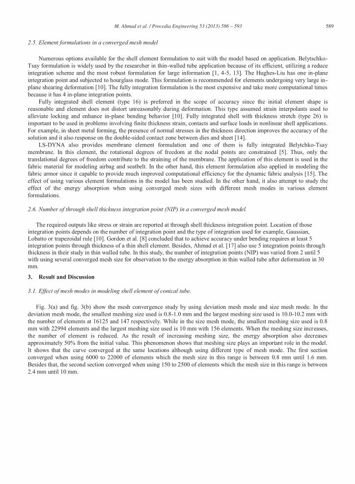
Fig. 5. Energy vs displacement for various meshing size in size mesh mode.
From the curve, it can be clearly seen that there is two groups of converged result which very significant to the totalenergy. This shows that numerical analysis is dependent for verification. Mathematical solution or experimental can beperform to obtain which meshing size should be use in numerical analysis.w
3.2. Effect of using hourglass control
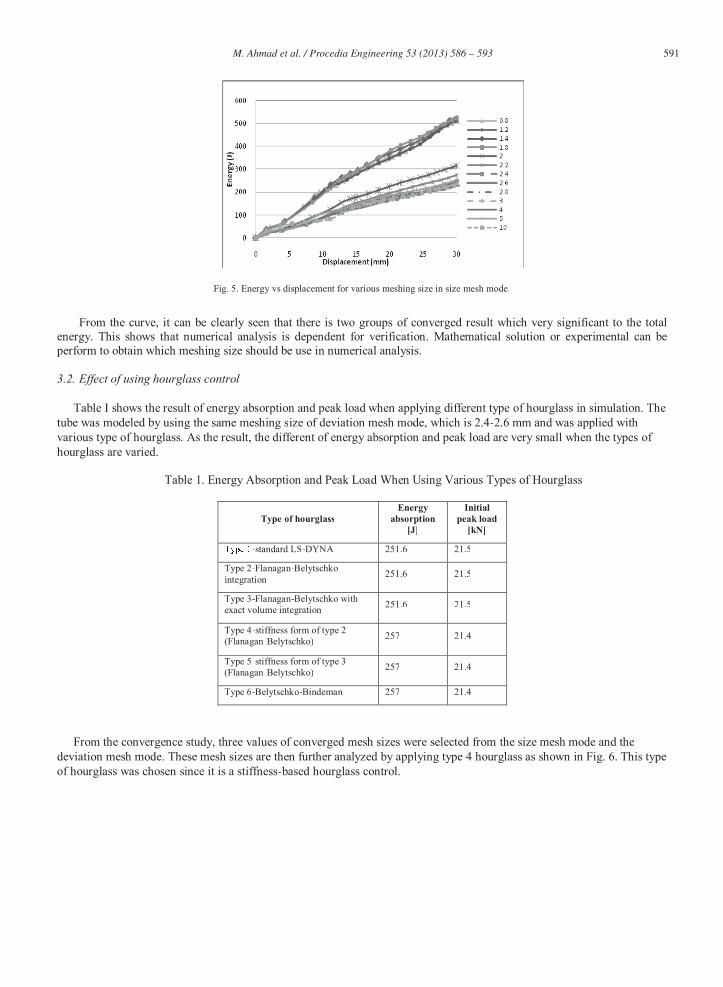
Table I shows the result of energy absorption and peak load when applying different type of hourglass in simulation. Thetube was modeled by using the same meshing size of deviation mesh mode, which is 2.4-2.6 mm and was applied withvarious type of hourglass. As the result, the different of energy absorption and peak load are very small when the types of hourglass are varied.
Table 1. Energy Absorption and Peak Load When Using Various Types of Hourglass
Type of hourglassEnergy
absorption[J]
Initialpeak load
[kN]
-standard LS-DYNA 251.6 21.5
Type 2-Flanagan-Belytschkointegration 251.6 21.5
Type 3-Flanagan-Belytschko withexact volume integration 251.6 21.5
Type 4-stiffness form of type 2(Flanagan-Belytschko) 257 21.4
Type 5-stiffness form of type 3(Flanagan-Belytschko) 257 21.4
Type 6-Belytschko-Bindeman 257 21.4
From the convergence study, three values of converged mesh sizes were selected from the size mesh mode and the deviation mesh mode. These mesh sizes are then further analyzed by applying type 4 hourglass as shown in Fig. 6. This typeof hourglass was chosen since it is a stiffness-based hourglass control.

592 M. Ahmad et al. / Procedia Engineering 53 ( 2013 ) 586 – 593
Fig. 6: Energy absorption vs deformation using hourglass type 4 in various converged meshing size.
It is widely used by the previous studies to avoid spurious zero energy deformation mode [4-6].In general, the energy increment shows good agreement through deformation for all meshing size applied.
3.3. Effect of using various type of element formulation
Fig. 7 shows the result of energy absorption when using the various type of element formulation. To check theconvergence for the shell element, the model is developed using type 1, 2 and 16. Again, the energy absorbed by the tube isalmost the same by using those element formulation types. However, type 26 and 9 exhibit slight differences in term of energy absorption since these element formulations are more suitable to be used in other scope of analysis.
Fig. 7. Energy absorption vs meshing size by using various type of element formulation.
The result of energy absorption is consistent when using different value of converged mesh size in each elementformulation. Either using size mesh mode or deviation mesh mode, both of them recorded the same value of energy absorption in a group of element formulation used. Thereby, it seems that using different type of mesh mode does not affectthe result significantly.
3.4. Effect of using various number of through shell thickness integration point
Fig. 8. Energy absorption vs meshing size by using different values of NIP.

593 M. Ahmad et al. / Procedia Engineering 53 ( 2013 ) 586 – 593
Based on this study, the number of through thickness point integration only shows minor differences between the simulations in term of energy absorption. However, the simulation results for different type of meshing mode demonstrate a predicted finding. The result in each section is still converged. It can be concluded the converged mesh size with various number of shell thickness integration point provides insignificant affect to the energy absorption result. However, using a single point integration through shell thickness (NIP=1) must be avoided because it will lead to instabilities and inaccurate result.
Conclusion
For crushing of thin-walled tube, it is very important for the researchers to perform mesh convergence study in order to obtain the required meshing size in creating the model since it can result in large variations to the output. It was shown in this study that using different method of meshing either a size mesh mode or a deviation mesh mode is insignificant to the output. The various types of control parameters in simulation such as hourglass, element formulation and number of through thickness integration can affect the results. However, when applying a group of converged mesh sizes in simulation with selected control parameter, the energy absorption and peak load will result in an almost similar value. It is recommended that either theoretical or experimental studies can be performed to obtain the most appropriate meshing size if there is more than one converge section in the convergence study.
References [1] H. Han, F. -static and dynamic crushing behaviors of aluminum and steel tubes w -Walled Struct, vol.
45, pp. 529-551, 2007. [2] S. Salehghaffari, M. R. -Walled Struct, vol.49, pp. 397-408,
2011. [3] Ø. Fyllingen, O. S. Hopperstad, A. G. Han -Walled Struct, vol48, pp. 134-
142, 2010. [4] - cs
and Material, vol. 165, pp. 130-134, 2011. [5] Z. Ahmad, D. P. Thambiratnam and A.C.C. -filled conical tubes under oblique impact
-488, 2010. [6] J. Bi, H. Fang, Q. -filled thin-
Analysis and Design, vol.46, pp. 698-709, 2010. [7] X. -451, 2010. [8] S. B. Gordon, D. P.
[9] N. M. Sheriff, N.K. Gupta, R. -Walled
Struct, vol. 46, pp. 653-666, 2008. [10] J. O Hallquist, LS-DYNA Theory Manual. Livermore Software Technology Corporation, 2006. [11] L. E. Schwer, S. W. Key, T. A. -
LS-DYNA Users Conference, paper publication. [12] L. Aktay, A. K. -static axial crushing of extruded polystyrene foam-filled thin-walled aluminium tubes: experimental and
-565, 2006. [13] 40, pp. 4427-4449,
1997. [14] nada, 2005.