conveyor aluminum extrusion
TRANSCRIPT
-13111 -13121
AlterationsCode
Spec.Left End Right End
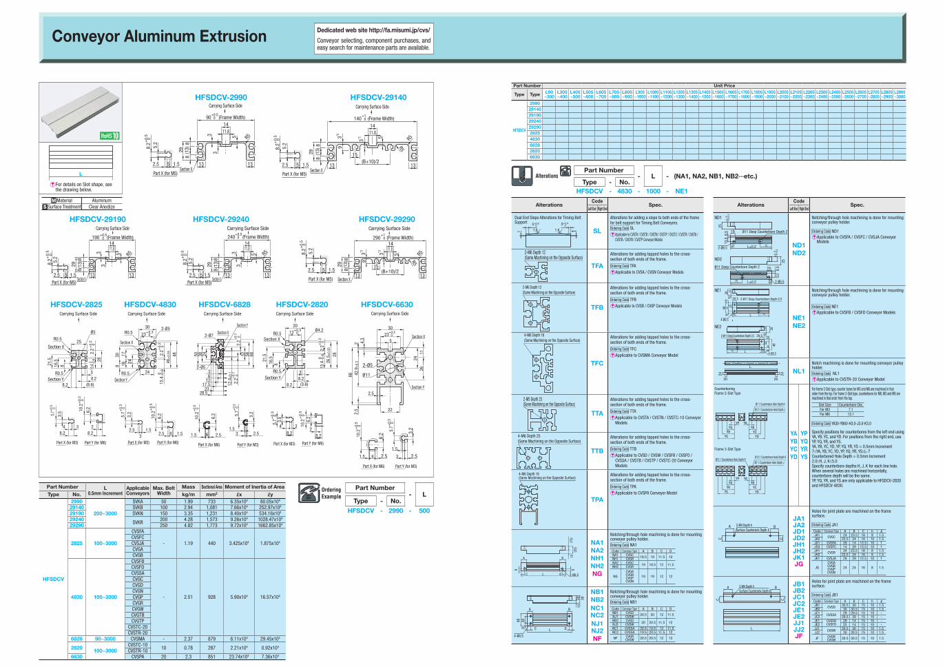
Dual End Slope Alterations for Timing Belt Support
SL
Alterations for adding a slope to both ends of the frame for belt support for Timing Belt Conveyors.Ordering Code SL
E��Applicable to CVSTA / CVSTB / CVSTN / CVSTP / CVSTC / CVSTR / CVGTA / CVGTB / CVGTN / CVGTP Conveyor Models
TFA
Alterations for adding tapped holes to the cross-section of both ends of the frame.
Ordering Code TFAEApplicable to CVSA / CVSN Conveyor Models
2-M6 Depth 12(Same Machining on the Opposite Surface)
TFB
Alterations for adding tapped holes to the cross-section of both ends of the frame.
Ordering Code TFB
EApplicable to CVSB / CVSP Conveyor Models
TFC
Alterations for adding tapped holes to the cross-section of both ends of the frame.
Ordering Code TFCEApplicable to CVSMA Conveyor Model
TTA
Alterations for adding tapped holes to the cross-section of both ends of the frame.
Ordering Code TTA
E��Applicable to CVSTA / CVSTN / CVSTC-10 Conveyor Models
4-M6 Depth 25(Same Machining on the Opposite Surface)
TTB
Alterations for adding tapped holes to the cross-section of both ends of the frame.
Ordering Code TTB
E��Applicable to CVSD / CVSW / CVSFB / CVSFD / CVSSA / CVSTB / CVSTP / CVSTC-20 Conveyor Models
TPA
Alterations for adding tapped holes to the cross-section of both ends of the frame.
Ordering Code TPAEApplicable to CVSPA Conveyor Model
A B
DC L8
10(1
5)(2
5)
8
2-Ø6.5
NA1NA2NH1NH2NG
Notching/through hole machining is done for mounting conveyor pulley holder.Ordering Code NA1Code Conveyor Type A B C DNA1 CVSC 18.5 19 11.5 12NH1 CVSRNA2 CVSC 19 18.5 12 11.5NH2 CVSR
NGCVGACVGBCVGPCVGN
19 19 12 1220 30
30488
10
A B
C DL
4-Ø6.5
NB1NB2NC1NC2NJ1NJ2NF
Notching/through hole machining is done for mounting conveyor pulley holder.Ordering Code NB1Code Conveyor Type A B C DNB1 CVSD 20.5 20 12 11.5NJ1 CVSWNB2 CVSD 20 20.5 11.5 12NJ2 CVSWNC1 CVSSA 20.5 19.5 12 11.5NC2 CVSSA 19.5 20.5 11.5 12
NF CVGRCVGW 20.5 20.5 12 12
1.6
5+0.40
1 11.6
5+0.40
2-M6 Depth 12(Same Machining on the Opposite Surface)
4-M6 Depth 16(Same Machining on the Opposite Surface)
2-M5 Depth 25(Same Machining on the Opposite Surface)
4-M6 Depth 18(Same Machining on the Opposite Surface)
AlterationsCode
Spec.Left End Right End
ND1
ND2
ND1ND2
Notching/through hole machining is done for mounting conveyor pulley holder.
Ordering Code ND1E��Applicable to CVSFA / CVSFC / CVSJA Conveyor
Models
NE1
NE2
NE1NE2
Notching/through hole machining is done for mounting conveyor pulley holder.
Ordering Code NE1E��Applicable to CVSFB / CVSFD Conveyor Models
L
20
24 24
20
NL1Notch machining is done for mounting conveyor pulley holder.Ordering Code NL1EApplicable to CVSTR-20 Conveyor Model
CounterboringFrame 2-Slot Type
Frame 3-Slot Type
YAYBYCYD
YPYQYRYS
For frame 2-Slot type, counter bores for M3 and M6 are machined in that order from the top. For frame 3-Slot type, counterbores for M6, M3 and M6 are machined in that order from the top.
Slot Size Counterbore Dia.For M3 7.1For M6 12.1
Ordering Code YA30-YB60-H3.0-J3.0-K3.0
Specify positions for counterbores from the left end using YA, YB, YC, and YD. For positions from the right end, use YP, YQ, YR, and YS.YA, YB, YC, YD, YP, YQ, YR, YS = 0.5mm Increment7≤YA, YB, YC, YD, YP, YQ, YR, YS≤L-7Counterbored Hole Depth = 0.5mm Increment2.0≤H, J, K≤5.0Specify counterbore depths H, J, K for each line hole.When several holes are machined horizontally, counterbore depth will be the same.YP, YQ, YR, and YS are only applicable to HFSDCV-2820 and HFSDCV-4830.
A
C C
B2-M4 Depth hSurface Countersink Depth l
JA1JA2JD1JD2JH1JH2JK1JG
Holes for joint plate are machined on the frame surface.
Ordering Code JA1Code Conveyor Type A B C h lJA1 CVSC 24 23.5 16 8 1.5JA2 23.5 24 16 10 1.5JD1 CVSFA 29 14 12.5 10 1JD2 CVSFC 14 29 12.5 10 1JH1 CVSR 24 23.5 16 8 1.5JH2 23.5 24 16 8 1.5JK1 CVSJA 29 29 12.5 10 1
JGCVGACVGBCVGPCVGN
24 24 16 8 1.5
A
C C
B2-M4 Depth hSurface Countersink Depth l
L
JB1JB2JC1JC2JE1JE2JJ1JJ2JF
Holes for joint plate are machined on the frame surface.
Ordering Code JB1Code Conveyor Type A B C h lJB1 CVSD 30.5 30 15 10 1.5JB2 30 30.5 15 10 1.5JC1 CVSSA 29 29.5 15 10 -JC2 29.5 29 15 10 -JE1 CVSFB
CVSFD29 14 15 10 -
JE2 25 14 15 10 -JJ1 CVSW 30.5 30 15 10 1.5JJ2 30 30.5 15 10 1.5
JF CVGRCVGW 30.5 30.5 15 10 1.5
Ø11 Deep Counterbore Depth 2
25
25
19
12
12
75
19
75
L±0.2
L±0.2
2-Ø6.5
2-Ø6.5
13.5
6.5
6.5
13.5
0
15-0
.3
0
15-0
.2
Ø11 Deep Counterbore Depth 2
Ø11 Deep Counterbore Depth 2
25
25
19
12
12
75
19
75
L±0.2
L±0.2
2-Ø6.5
2-Ø6.5
13.5
6.5
6.5
13.5
0
15-0
.3
0
15-0
.2
Ø11 Deep Counterbore Depth 2
2-Ø11 Deep Counterbore Depth 2.5
4-Ø6.5
3048
1410
3020
108 12
20.5
75L
302010
10
2-Ø11 Deep Counterbore Depth 2.5
4-Ø6.5
30 48
14812
20.5
75 L
2-Ø11 Deep Counterbore Depth 2.5
4-Ø6.5
3048
1410
3020
108 12
20.5
75L
302010
10
2-Ø11 Deep Counterbore Depth 2.5
4-Ø6.5
30 48
14812
20.5
75 L
YPYQ
YRYS
YAYB
YCYD
YPYQ
YRYS
YAYB
YCYD
Ø7.1 Counterbore Hole Depth H
Ø12.1 Counterbore Hole Depth J
Ø12.1 Counterbore Hole Depth H
Ø7.1 Counterbore Hole Depth JØ12.1 Counterbore Hole Depth K
YPYQ
YRYS
YAYB
YCYD
YPYQ
YRYS
YAYB
YCYD
Ø7.1 Counterbore Hole Depth H
Ø12.1 Counterbore Hole Depth J
Ø12.1 Counterbore Hole Depth H
Ø7.1 Counterbore Hole Depth JØ12.1 Counterbore Hole Depth K
Conveyor Aluminum Extrusion
Part Number- L - (NA1, NA2, NB1, NB2∙∙∙etc.)
Type - No.HFSDCV - 4830 - 1000 - NE1
Part Number- L
Type - No.
HFSDCV - 2990 - 500
L
Part Number L0.5mm Increment
ApplicableConveyors
Max. Belt Width
Mass Sectional Area Moment of Inertia of AreaType No. kg/m mm2 Lx Ly
HFSDCV
2990
200~3000
SVKA 50 1.99 733 6.35x10⁴ 80.05x10⁴
29140 SVKB 100 2.94 1,081 7.66x10⁴ 252.97x10⁴
29190 SVKN 150 3.35 1,231 8.40x10⁴ 534.16x10⁴
29240SVKR
200 4.28 1,573 9.26x10⁴ 1028.47x104
29290 250 4.82 1,773 9.72x10⁴ 1662.85x104
2825 100~3000
CVSFA
- 1.19 440 3.425x10⁴ 1.875x10⁴CVSFCCVSJACVGACVGB
4830 100~3000
CVSFB
- 2.51 928 5.90x10⁴ 16.57x10⁴
CVSFDCVSSACVGCCVGDCVGNCVGPCVGRCVGWCVGTBCVGTP
CVSTC-20CVSTR-20
6828 90~3000 CVSMA - 2.37 879 6.11x10⁴ 29.45x10⁴
2820 100~3000CVSTC-10
10 0.78 287 2.21x10⁴ 0.92x10⁴
CVSTR-106630 CVSPA 20 2.3 851 23.74x10⁴ 7.36x10⁴
E��For details on Slot shape, see the drawing below.
Part Number Unit Price
Type Type L90~300
L305~400
L405~500
L505~600
L605~700
L705~800
L805~900
L905~1000
L1005~1100
L1105~1200
L1205~1300
L1305~1400
L1405~1500
L1505~1600
L1605~1700
L1705~1800
L1805~1900
L1905~2000
L2005~2100
L2105~2200
L2205~2300
L2305~2400
L2405~2500
L2505~2600
L2605~2700
L2705~2800
L2805~2900
L2905~3000
HFSDCV
29902914029190292402929028254830682828206630
MMaterial AluminumSSurface Treatment Clear Anodize
HFSDCV-2990
(13)
88
29
(B+10)/213
1411.8
2.5 1.55
5.2
8.2+
0.5
0
Carrying Surface Side3*2
13
15
R5
Section X
3*2 5
9
R5
3
(13)29
Section X
8
13
8
3
5
13
1411.8
R5
Carrying Surface Side
Part X (for M5)
90 (Frame Width)+0.5 0
140 (Frame Width)+1
0
HFSDCV-29140
(13)
88
29
(B+10)/213
1411.8
2.5 1.55
5.2
8.2+
0.5
0
Carrying Surface Side
3*2
13
15
R5
Section X
3*2 5
9
R5
3
(13)29
Section X
8
13
8
3
5
13
1411.8
R5
Carrying Surface Side
Part X (for M5)
90 (Frame Width)+0.5 0
140 (Frame Width)+1
0
(13)
88
29
(B+10)/213
1411.8
2.5 1.55
5.2
8.2+
0.5
0
Carrying Surface Side
3*2
13
15
R5
Section X
3*2 5
9
R5
3
(13)29
Section X
8
13
8
3
5
13
1411.8
R5
Carrying Surface Side
Part X (for M5)
90 (Frame Width)+0.5 0
140 (Frame Width)+1
0
HFSDCV-29190 HFSDCV-29290HFSDCV-29240
(13)
88
29
(B+10)/213
1411.8
2.5 1.55
5.2
8.2+
0.5
0
Carrying Surface Side
3*2
13
15
R5
Section X3*2 5
9
R5
3
(13)29
Section X
8
13
8
3
5
13
1411.8
R5
Carrying Surface Side
Part X (for M5)
90 (Frame Width)+0.5 0
140 (Frame Width)+1
0
(13)
88
29
B+40 (Frame Width)
(B+10)/213
1411.8
2.5 1.55
5.2
8.2+
0.5
0
Carrying Surface Side
3*2
13
15
R5
Section X
3*2 5
9
R5
190 (Frame Width)
3
(13)29
Section X
8
13
8
3
5
13
1411.8
R5
Carrying Surface Side
Part X (for M5)
+0.5 0
+1 0
(13)
88
29
(B+10)/213
1411.8
2.5 1.55
5.2
8.2+
0.5
0
Carrying Surface Side
3*2
13
15
R5
Section X
3*2 5
9
R5
3
(13)29
Section X
8
13
8
3
5
13
1411.8
R5
Carrying Surface Side
Part X (for M5)
290 (Frame Width)+1
0
240 (Frame Width)+0.5 0
(13)
88
29
(B+10)/213
1411.8
2.5 1.55
5.2
8.2+
0.5
0
Carrying Surface Side
3*2
13
15
R5
Section X
3*2 5
9
R5
3
(13)29
Section X
8
13
8
3
5
13
1411.8
R5
Carrying Surface Side
Part X (for M5)
290 (Frame Width)+1
0
240 (Frame Width)+0.5 0
30
5
1126
24
22
2.5
2.5
662
42.9
±0.
3
4.3 Section X
Section Y
10.2
6.2
1.5 6 2.5
5.7
1.5
3 2.5
3.2
Carrying Surface Side
2-Ø5
Ø11
23 +0.3 0
+0.
5
0 +0.
3
0
Part X (for M6) Part Y (for M3)
HFSDCV-2825 HFSDCV-4830 HFSDCV-6828 HFSDCV-2820 HFSDCV-6630
28
2.2
+0.
20
25
816.5
21.5
8.2 (8.6)8.23
8.22
6.210
.2+
0.5
0
8.24 3
3.55.7+0
.3 0
Section X
Section Y
R0.5
R0.5
Part Y (for M6)Part X (for M3)
Ø5Carrying Surface Side
15.4
0
-0.6
28
2.2
+0.
20
25
816.5
21.5
8.2 (8.6)8.23
8.22
6.210
.2+
0.5
0
8.24 3
3.55.7+0
.3 0
Section X
Section Y
R0.5
R0.5
Part Y (for M6)Part X (for M3)
Ø5Carrying Surface Side
15.4
0
-0.6
28
2.2
+0.
20
25
816.5
21.5
8.2 (8.6)8.23
8.22
6.210
.2+
0.5
0
8.24 3
3.55.7+0
.3 0
Section X
Section Y
R0.5
R0.5
Part Y (for M6)Part X (for M3)
Ø5Carrying Surface Side
15.4
0
-0.6 28
2.2
+0.
20
25
816.5
21.5
8.2 (8.6)8.23
8.22
6.210
.2+
0.5
0
8.24 3
3.55.7+0
.3 0
Section X
Section Y
R0.5
R0.5
Part Y (for M6)Part X (for M3)
Ø5Carrying Surface Side
15.4
0
-0.6
28
2.2
+0.
20
25
816.5
21.5
8.2 (8.6)8.23
8.22
6.210
.2+
0.5
0
8.24 3
3.55.7+0
.3 0
Section X
Section Y
R0.5
R0.5
Part Y (for M6)Part X (for M3)
Ø5Carrying Surface Side
15.4
0
-0.6
32.5
3.2
5.7+
0.3
0
6.2
10.2
+0.
50
15
.40
-0.6
2.2+
0.2
0
46±
0.35 48
1.5
Part X (for M3) Part Y (for M6)
1.562.5
23+0.30
30
24
241617
830
2-Ø5
Section X
R0.5Section Y
R0.5
Carrying Surface Side
32.5
3.2
5.7+
0.3
0
6.2
10.2
+0.
50
15
.40
-0.6
2.2+
0.2
0
46±
0.35 48
1.5
Part X (for M3) Part Y (for M6)
1.562.5
23+0.30
30
24
241617
830
2-Ø5
Section X
R0.5Section Y
R0.5
Carrying Surface Side
32.5
3.2
5.7+
0.3
0
6.2
10.2
+0.
50
15
.40
-0.6
2.2+
0.2
0
46±
0.35 48
1.5
Part X (for M3) Part Y (for M6)
1.562.5
23+0.30
30
24
241617
830
2-Ø5
Section X
R0.5Section Y
R0.5
Carrying Surface Side 30
5
1126
2422
2.5
2.5
662
42.9
±0.
3
4.3 Section X
Section Y
10.2
6.2
1.5 6 2.5
5.7
1.5
3 2.5
3.2
Carrying Surface Side
2-Ø5
Ø11
23 +0.3 0
+0.
5
0 +0.
3
0
Part X (for M6) Part Y (for M3)
243850
63
1217.5
2328.5
12.4
±0.
1
2.2
2.2
5632 68
Carrying Surface Side
Section X
Section Y
2-Ø5
2-Ø7
+0.
1
0
+0.
1
0
10.2
6.2
1.5 6 2.5
5.7
3.2
1.53 2.5
+0.
5
0
+0.
3
0
Part X (for M6) Part Y (for M3)
10.2
6.2
1.5 6 2.5
5.7
3.2
1.53 2.5
+0.
5
0
+0.
3
0
Part X (for M6) Part Y (for M3)
28
2.2
+0.
20
25
816.5
21.5
8.2 (8.6)8.23
8.22
6.210
.2+
0.5
0
8.24 3
3.55.7+0
.3 0
Section X
Section Y
R0.5
R0.5
Part Y (for M6)Part X (for M3)
Ø5Carrying Surface Side
15.4
0
-0.6
2026
.5±
0.35
816.521
.5 28Ø4.2
R0.5Section X
R0.5Section Y
8.2 (3.6)8.23
12+0.3 0
15.4
0
-0
.62.
2+0.
2 0
Carrying Surface Side
8.2
4 3
3.5
5.7+
0.3
0
Part X (for M3)
6.2
28.2
10.2
+0
.5
0
Part Y (for M6)
28
2.2
+0.
20
25
816.5
21.5
8.2 (8.6)8.23
8.22
6.210
.2+
0.5
0
8.24 3
3.55.7+0
.3 0
Section X
Section Y
R0.5
R0.5
Part Y (for M6)Part X (for M3)
Ø5Carrying Surface Side
15.4
0
-0.6 28
2.2
+0.
20
25
816.5
21.5
8.2 (8.6)8.23
8.22
6.210
.2+
0.5
0
8.24 3
3.55.7+0
.3 0
Section X
Section Y
R0.5
R0.5
Part Y (for M6)Part X (for M3)
Ø5Carrying Surface Side
15.4
0
-0.6
Dedicated web site http://fa.misumi.jp/cvs/
Conveyor selecting, component purchases, and easy search for maintenance parts are available.