cooking lake 2006 final aug12 - alberta lake management society
TRANSCRIPT
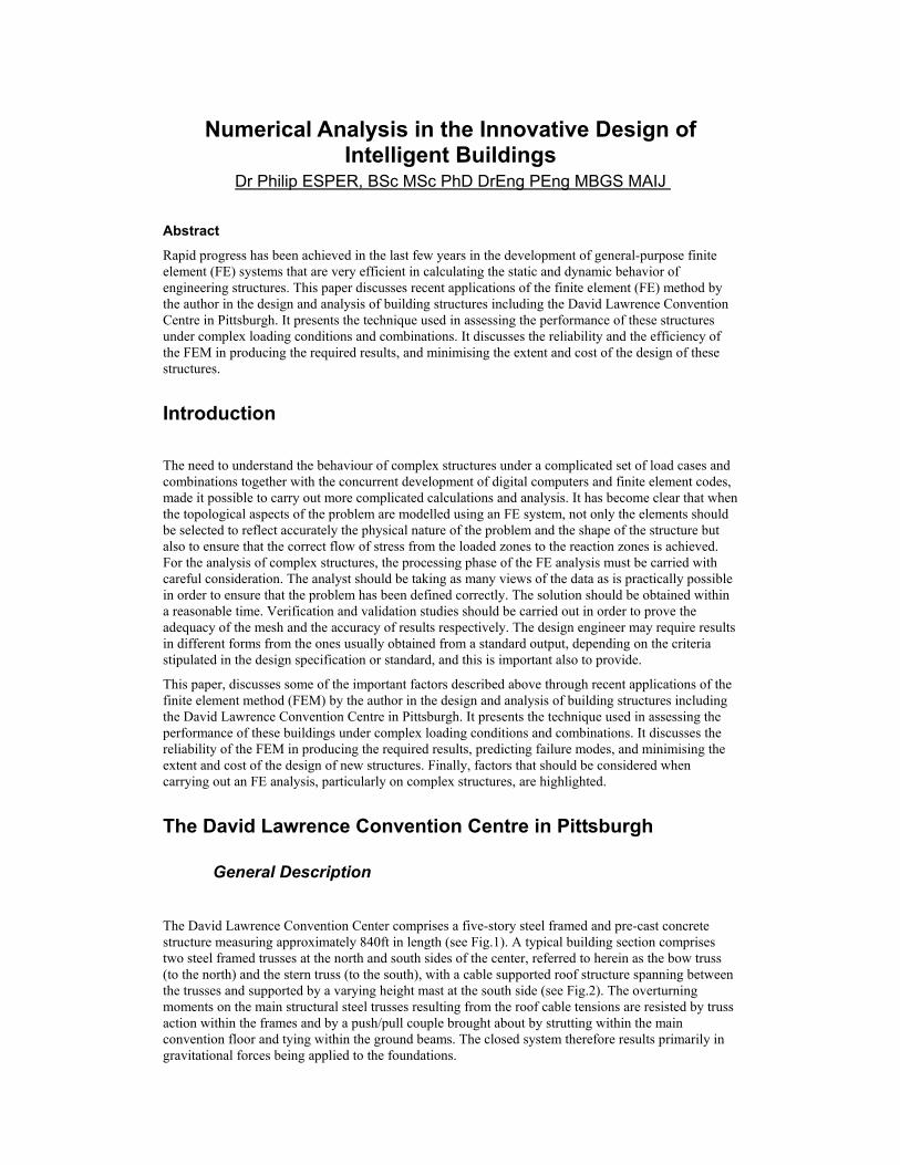
Numerical Analysis in the Innovative Design of Intelligent Buildings
Dr Philip ESPER, BSc MSc PhD DrEng PEng MBGS MAIJ Abstract
Rapid progress has been achieved in the last few years in the development of general-purpose finite element (FE) systems that are very efficient in calculating the static and dynamic behavior of engineering structures. This paper discusses recent applications of the finite element (FE) method by the author in the design and analysis of building structures including the David Lawrence Convention Centre in Pittsburgh. It presents the technique used in assessing the performance of these structures under complex loading conditions and combinations. It discusses the reliability and the efficiency of the FEM in producing the required results, and minimising the extent and cost of the design of these structures.
Introduction
The need to understand the behaviour of complex structures under a complicated set of load cases and combinations together with the concurrent development of digital computers and finite element codes, made it possible to carry out more complicated calculations and analysis. It has become clear that when the topological aspects of the problem are modelled using an FE system, not only the elements should be selected to reflect accurately the physical nature of the problem and the shape of the structure but also to ensure that the correct flow of stress from the loaded zones to the reaction zones is achieved. For the analysis of complex structures, the processing phase of the FE analysis must be carried with careful consideration. The analyst should be taking as many views of the data as is practically possible in order to ensure that the problem has been defined correctly. The solution should be obtained within a reasonable time. Verification and validation studies should be carried out in order to prove the adequacy of the mesh and the accuracy of results respectively. The design engineer may require results in different forms from the ones usually obtained from a standard output, depending on the criteria stipulated in the design specification or standard, and this is important also to provide.
This paper, discusses some of the important factors described above through recent applications of the finite element method (FEM) by the author in the design and analysis of building structures including the David Lawrence Convention Centre in Pittsburgh. It presents the technique used in assessing the performance of these buildings under complex loading conditions and combinations. It discusses the reliability of the FEM in producing the required results, predicting failure modes, and minimising the extent and cost of the design of new structures. Finally, factors that should be considered when carrying out an FE analysis, particularly on complex structures, are highlighted.
The David Lawrence Convention Centre in Pittsburgh
General Description The David Lawrence Convention Center comprises a five-story steel framed and pre-cast concrete structure measuring approximately 840ft in length (see Fig.1). A typical building section comprises two steel framed trusses at the north and south sides of the center, referred to herein as the bow truss (to the north) and the stern truss (to the south), with a cable supported roof structure spanning between the trusses and supported by a varying height mast at the south side (see Fig.2). The overturning moments on the main structural steel trusses resulting from the roof cable tensions are resisted by truss action within the frames and by a push/pull couple brought about by strutting within the main convention floor and tying within the ground beams. The closed system therefore results primarily in gravitational forces being applied to the foundations.

The building is split into fifteen of the above-mentioned sections at 60 ft centers with roof spans ranging from approximately 300 ft to 400 ft. Overall stability is provided via floor diaphragm action by reinforced concrete shear walls within cores at either side of the building at five truss locations along the length of the building. The roof is discontinuous at one location where a walkway is provided over the main convention floor. The cable system forming the roof comprises a main cable with an inclined span, anchored back from the bow truss, rising over the main support mast and back down to the stern truss. A smaller lower cambered cable is also provided to allow pre-tensioning of the system and to provide geometric control. The upper and lower cables are connected together via hanger cables located at 30 ft centers. The level of pre-stress within the system, and the required architectural geometry is achieved by varying the pre-load values within these hangers. Secondary lower cables hung from the main upper cables are also provided to give a 30 ft conference support grid.
The main cable construction consists of 169 No 0.6” diameter galvanized pre-stressing strands bundled to form a hexagonal cable cross section. The lower cable consists of a single 4” diameter galvanized structural strand. The hanger cables consist of 1” or 1 5/16” diameter galvanized structural strand. Cable sizing have been made based on the guidance given in ASCE Standard 19-96, Structural Applications of Steel Cables for Buildings. Due to the significant magnitude of deflection of the roof cables, a traditional linear analysis of the structure is not valid. This was further magnified by flexibility of the supporting structural steel frame during construction. Early on in the design process it was recognized that adjustment of the system would be required to ensure that the design geometry and preloads could be accurately achieved. To enable on-site observations to be correctly assessed against the design intent, extensive use of computer modelling was required and used as the basis for the on-site adjustment activities. Computer modelling was also required for the final design of both the roof cables and the cable supported end walls.
Figure 1. The David Lawrence Convention Centre, Pittsburgh, USA.

Figure 2. A Typical section through the David Lawrence Convention Centre.
Design and Analysis of Roof Cables
The design of the cables was carried out using Finite Element software (Larsa) utilizing a non-linear analysis (see Figs.3&4). The following iterative process for development of typical cable models was adopted:
(a) Determine a distribution of hanger preloads within the span required to achieve a geometry as close as is possible to that the required architecturally, using a hanger preload in the region of between 30 to 45% of the roof dead load.
(b) Refine the lower and upper cable profiles and pre-stress so as to be compatible with the distribution of hanger point loads determined from (a), and hence produce zero dead load deflection computer models for each of the cables separately. This was carried out by deactivating the hanger elements and replacing them with point loads.
(c) Re- introduce the hanger cables with preloads as those determined in (a).
(d) Using the model created in (c), perform roof snow and wind load response analyses to determine whether an adequate level of pre-stress has been adopted to ensure that the lower cable remains in nominal tension under the various loading conditions. If the lower cable is found to become slack under any of the loading conditions, the hanger preloads are factored up and steps (b) & (c) repeated with the increased hanger preloads.
(e) With an acceptable level of pre-stress and compatible geometry finalized, the cable tensions, natural frequencies, modal shapes and deflections are determined for use in the cable sizing, connection design, wind tunnel testing to determine the dynamic response, and the main steel building frame design.
(f) Final adjustment to the preloads and cable areas are made to compensate for construction deflection of the main building steel frame due to the cable tensions, mast rotation movement, limitations in differential deflections between roof panels, and dynamic response effects.

(g) With the final cable design tensions determined, constructional setting out, cable lengths, connection locations and working tension levels can be produced by removing the roof dead load from the model. This provides the information necessary for the fabrication and installation of the cables, and forms the basis for the building erection design and analysis.
Figure 3. Larsa 3-D Finite Element Model.
Figure 4. The site during the construction of the David Lawrence Convention Centre.
Erection Analysis To optimize the efficiency of the structure a hybrid arrangement was adopted for the overall building steel framing. The closed system described above, where the cable forces are resisted internally within the building frame, was chosen as the main structural arrangement to resist cable forces during construction. This minimized the loads applied to the foundations. However, due to strain within structural steel, semi-rigidity of connections and foundation movement, this arrangement was found to be unsuitable for the building service condition due to steel frame movement, which in turn caused excessive movement of the cable roof structure. It was therefore decided to adopt the closed system arrangement during construction and to “lock” the structure into position after cable tensioning by means of the slab diaphragm connections to the concrete cores, and by inclusion of a stabilizing “raking strut” steel member.
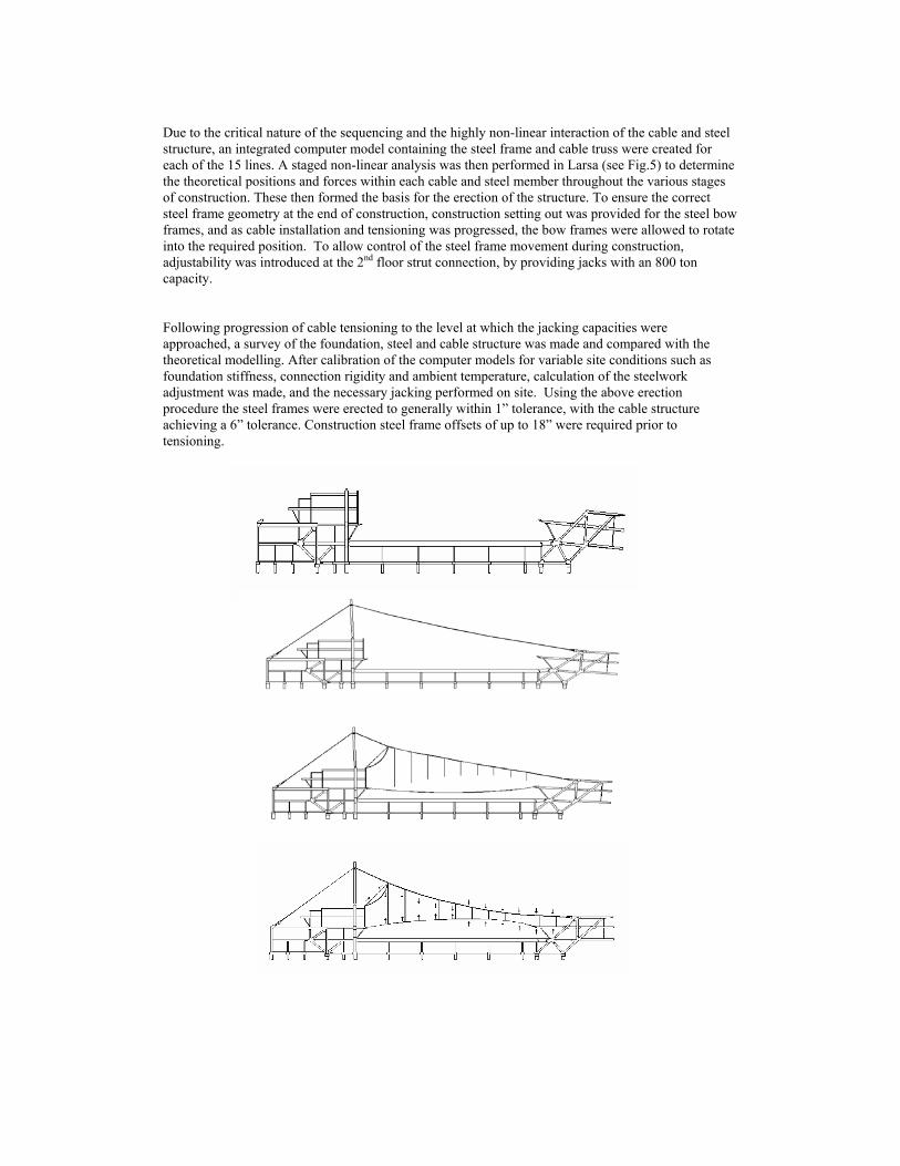
Due to the critical nature of the sequencing and the highly non-linear interaction of the cable and steel structure, an integrated computer model containing the steel frame and cable truss were created for each of the 15 lines. A staged non-linear analysis was then performed in Larsa (see Fig.5) to determine the theoretical positions and forces within each cable and steel member throughout the various stages of construction. These then formed the basis for the erection of the structure. To ensure the correct steel frame geometry at the end of construction, construction setting out was provided for the steel bow frames, and as cable installation and tensioning was progressed, the bow frames were allowed to rotate into the required position. To allow control of the steel frame movement during construction, adjustability was introduced at the 2nd floor strut connection, by providing jacks with an 800 ton capacity.
Following progression of cable tensioning to the level at which the jacking capacities were approached, a survey of the foundation, steel and cable structure was made and compared with the theoretical modelling. After calibration of the computer models for variable site conditions such as foundation stiffness, connection rigidity and ambient temperature, calculation of the steelwork adjustment was made, and the necessary jacking performed on site. Using the above erection procedure the steel frames were erected to generally within 1” tolerance, with the cable structure achieving a 6” tolerance. Construction steel frame offsets of up to 18” were required prior to tensioning.

Figure 5. Erection Analysis using Larsa.
Tokyo International Forum Yurakucho Glass Canopy
General Description The architectural concept was to create a cantilevered structure using as far as possible only glass (see Fig.6). The plan area of the canopy was 5m wide and 10m long. The roof of the canopy was to be covered with 10 glass sheets measuring 2.5m by an average of 2.2m supported on three 10m long glass cantilever beams spaced at 1.67
The cantilever beams were connected to a stainless steel torsion tube close to ground level.
The wind loading criteria was initially assessed as pressure coefficients for a freestanding mono-pitch canopy roof and established from a wind tunnel study giving upward and downward pressures at the tip of canopy of up to 5kN/m2. In addition the earthquake design criteria was based on time histories from four earthquakes: El Centro, Taft, Tokyo 101 and Hachinohe. As the maximum length of fully toughened sheets available at that time was 5m, it was decided to fabricate the ten metre long beams from four overlapping elements to minimise the force at the connection points. The element nearest the support was 5m long and the element at the tip was just under 4m long with the elements reducing in length and each element overlapped its neighbour by an average of 2m.

Figure 6. Tokyo International Forum Yurakucho Glass Canopy.
Computer Modelling and Analysis An extensive finite element (FE) analysis of the entire structure was undertaken using LUSAS particularly to measure its response to earthquake loading (see Figs.7-9). The cantilever beam elements, roof panels and support brackets were modelled using 3-D thin shell elements. The connecting pins between the glass and the horizontal support beams were modelled using thick beam elements. The connections between the glass and the pins were modelled using 3-D joint elements, with free rotation about the pins axes. A moderately coarse mesh was used for the analysis of the canopy. This provided accurate mode shapes, static and dynamic deflections along with accurate forces and moments in the joints. The background stresses in the shells proved reasonably accurate, although stress results around the joints will not include local effects. The effect of stress concentrations locally around the holes was investigated by physical testing. The static analysis considered self-weight, front and rear wind loading and thermal differential expansion. The seismic analyses included an Eigenvalue Analysis to determine the major modes, followed by a Spectral Response calculation to estimate the peak induced forces and stresses. The Spectral Response calculation requires a spectral curve describing the frequency content of a given time history of excitation. The spectral curve is unique to the location of the structure and depends on the regularity and magnitude of expected seismic events. The ground accelerations from the spectral curve were applied to the structure in all three global directions in separate analyses. The spectral mode combination used for this analysis was CQC (Complete Quadratic Combination). The results produced were the maximum values from an envelope of the CQC values. The final spectral curve used to analyse the structure was based on 2% of critical damping. In the final analysis all modes were subject to a spectral acceleration of 6m/s2. It was noted that the frequencies obtained from Eigenvalue analyses are sensitive to the stiffness assumed at the joints between the glass and connecting beams.

Figure 7. LUSAS Model of the Glass Canopy – Deflected Shape under Self-weight.
Analysis Results The results from the Spectral Response analyses showed the maximum stress levels in the second cantilever beam from the tip. Out of plane bending is induced in the cantilevers by the transverse seismic load input. The results from the Spectral Response analyses are highly dependent on the level of damping assumed (see Fig.9). In order to establish the load capacity of the bolted connections an intense programme of physical testing was carried out at a University laboratory. Initially, direct tension tests were carried out on 19mm thick glass samples 600mm long and 200mm wide. Results gave a mean failure load of 77kN. The predicted value by elastic analysis in Peterson (1974) Stress Concentration Factors, allowing for stress concentrations around holes, was 79kN. With the ability to predict accurately stress concentrations for certain holes sizes, a special testing rig was fabricated to test the bending failure of glass samples. Subsequent tests included full scale mock-ups on glass beams over 5m long and 750mm deep with applied simulated loading and strain gauges to record stress levels in the glass. This research programme resulted in a clearer picture of the strength of toughened glass and provided us with sufficient data to design the bolted connections with confidence.
Structural Design The ten metre long cantilever beams were each constructed of 14 individual glass elements. The blade nearest the tip of the cantilever was fabricated from an identical pair of 12mm thick toughened glass elements and the remaining three elements were each structured from two pairs of 19mm thick elements laminated to provide two separate beams of approximately 40mm thickness with a maximum depth of 40mm. The elements were laminated using a UV cured acrylic resin. The beams were designed with a factor of safety of 8 on the basis that the critical beams at the root of the cantilever could lose three of the four glass elements and still support the most extreme loading condition with a factor of safety of 2. The lamination of the elements also ensured that complete failure of a laminated element would not result in heavy pieces of glass falling to the ground. Each individual glass element

and all the laminated pairs were fully tested to three time working load before installation in the works. Strain gauges were installed to monitor the performance of the elements and all 21 laminated pairs passed this test successfully with stress levels close to those predicted by calculation.
Figure 8. Principle Tensile Stresses.
Figure 9. Deflected Shape of the Glass Canopy under Spectral Load.
The Scottish Parliament House in Edinburgh One of the greatest sources of injuries and internal disruption from an external bomb explosion is the fragmentation of conventional annealed glass in windows which, when it breaks, does so in the form of dagger-like shards. Toughened glass will shatter at higher load than annealed glass and forms dice-shaped particles rather than elongated shards. Although less hazardous than annealed glass shards, these toughened “dice”, traveling at high velocity, can still cause injuries deep inside the building. The most effective protection to reduce this hazard is to use laminated glass anchored to its supporting frame in deep rebates (typically 25-30mm deep). When broken, the laminated glass remains stuck to the interlayer material rather than forming shards. By securely bonding the pane to its frame by means of a structural sealant, the interlayer can act as a ductile membrane, which bulges inward. By remaining intact the membrane prevents blast pressures and debris entering the building. If the membrane is stretched beyond the limit of its ductility, it will tear at mid-pane rather than at the perimeter and so that the pieces of the torn laminate remain attached to their frame. The effectiveness of laminated glass used in this way, in combination with appropriate frames and fixings to the structure, is well proven in both tests and actual terrorist bomb explosions. Empirically derived data exists for a range of glass types and thicknesses in the form of iso-damage curves plotted against pressure and impulse 2 . From such charts the façade designer can determine the likely level of damage that a particular glazing configuration will sustain under a given blast event.
Analytical techniques to model the behavior of laminated glass under transient loads are not yet well established. By developing suitable numerical methods and validating them against the empirical data referred to above, it should be possible to design glazing systems that can meet the demands for natural light and transparency required in many current buildings, while achieving at the same time a worthwhile level of blast resistance. FE models which combine elements to reliably simulate the post-crack behavior of laminated glass and their metal framing, would also allow full benefit to be taken of the ductility in such systems to minimize the blast loads imparted by the glass to the frames and by the frames to the primary structure of the building. Preliminary work has been undertaken using ANSYS and LS-DYNA to develop computationally efficient methods of modeling single laminated glass windows (see Fig.10) under a representative blast pressure-time history. While further investigation and testing is required to confirm the high strain rate properties of the polyvinyl butyral interlayer, the analytical results to date show promise in terms of the predicted reactions on frames, deformations, glass fracture patterns, and energy balance versus time. FE modeling (using LUSAS) of the response of wall panels and the design of fixing bolts to the structure has been also performed by the author as part of the design of the recently built Scottish Parliament House in Edinburgh (see Figs.11&12).

Figure 10. Progressive glass failure under blast loading.

Figure11. The Scottish Parliament House – Wall Panels.
Figure 12. FE model and Mxy contour plot of a wall panel response to blast pressures.
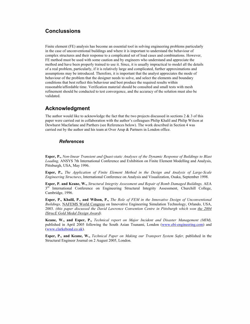
Conclussions Finite element (FE) analysis has become an essential tool in solving engineering problems particularly in the case of unconventional buildings and where it is important to understand the behaviour of complex structures and their response to a complicated set of load cases and combinations. However, FE method must be used with some caution and by engineers who understand and appreciate the method and have been properly trained to use it. Since, it is usually impractical to model all the details of a real problem, particularly, if it is relatively large and complicated, further approximations and assumptions may be introduced. Therefore, it is important that the analyst appreciates the mode of behaviour of the problem that the designer needs to solve, and select the elements and boundary conditions that best reflect this behaviour and best produce the required results within reasonable/affordable time. Verification material should be consulted and small tests with mesh refinement should be conducted to test convergence, and the accuracy of the solution must also be validated.
Acknowledgment The author would like to acknowledge the fact that the two projects discussed in sections 2 & 3 of this paper were carried out in collaboration with the author’s colleagues Philip Khalil and Philip Wilson at Dewhurst Macfarlane and Parthers (see References below). The work described in Section 4 was carried out by the author and his team at Over Arup & Partners in London office.
References Esper, P., Non-linear Transient and Quasi-static Analyses of the Dynamic Response of Buildings to Blast Loading, ANSYS 7th International Conference and Exhibition on Finite Element Modelling and Analysis, Pittsburgh, USA, May 1996.
Esper, P., The Application of Finite Element Method in the Design and Analysis of Large-Scale Engineering Structures, International Conference on Analysis and Visualization, Osaka, September 1998.
Esper, P. and Keane, W., Structural Integrity Assessment and Repair of Bomb Damaged Buildings, AEA 3rd International Conference on Engineering Structural Integrity Assessment, Churchill College, Cambridge, 1996.
Esper, P., Khalil, P., and Wilson, P., The Role of FEM in the Innovative Design of Unconventional Buildings, NAFEMS World Congress on Innovative Engineering Simulation Technology, Orlando, USA, 2003. (this paper discussed the David Lawrence Convention Centre in Pittsburgh which won the 2004 IStrucE Gold Medal Design Award).
Keane, W., and Esper, P., Technical report on Major Incident and Disaster Management (MIM), published in April 2005 following the South Asian Tsunami, London (www.ebi-engineering.com) and (www.clarkebond.co.uk).
Esper, P., and Keane, W., Technical Paper on Making our Transport System Safer, published in the Structural Engineer Journal on 2 August 2005, London.