cool hand automated arm
TRANSCRIPT

COOL HANDAUTOMATED ARM
EXPERT 2000™
Part #47182 rev. 1Release date: March 2007

EXPERT 2000
13-2

13-3
COOL HAND AUTOMATED ARM
13.0 COOL HAND AUTOMATED ARM MAINTENANCE .................................... 13 - 7
13.1 HYDRAULIC SYSTEM ........................................................................................... 13 - 713.1.1 GENERAL DESCRIPTION .................................................................................... 13 - 713.1.2 TANDEM PUMP ...................................................................................................... 13 - 813.1.3 VANE PUMP ............................................................................................................ 13 - 913.1.4 PISTON PUMP ....................................................................................................... 13 - 1013.1.5 PRESSURIZED TANK .......................................................................................... 13 - 1113.1.6 PUMP INSPECTION ............................................................................................. 13 - 1213.1.7 PUMP EMERGENCY SHUTDOWN ................................................................... 13 - 1313.1.8 PUMP PRIMING PROCEDURE .......................................................................... 13 - 14
13.2 HYDRAULIC PRESSURE ADJUSTMENT .........................................................13 - 1513.2.1 VANE PUMP RELIEF VALVE ADJUSTMENT ................................................. 13 - 1513.2.2 PISTON PUMP ADJUSTMENT........................................................................... 13 - 1713.2.3 LOAD SENSE PRESSURE ADJUSTMENT ...................................................... 13 - 1813.2.4 PISTON PUMP PRESSURE ADJUSTMENT ..................................................... 13 - 1913.2.5 INNER BOOM RELIEF VALVE .......................................................................... 13 - 1913.2.6 GRABBER PRESSURE ADJUSTMENT ............................................................ 13 - 2113.2.7 CYLINDER CUSHION ADJUSTMENT ............................................................. 13 - 2113.2.8 ARM SPEED ADJUSTMENT .............................................................................. 13 - 2613.2.9 OUTER BOOM RESTRICTOR ADJUSTMENT................................................ 13 - 2713.2.10 INNER BOOM LOCK VALVE ADJUSTMENT................................................. 13 - 2813.2.11 GRABBER LOCK VALVE ADJUSTMENT ....................................................... 13 - 2913.2.12 PRESSURIZED HYDRAULIC TANK ................................................................ 13 - 30
13.3 ELECTRICAL SYSTEMS ......................................................................................13 - 3113.3.1 ELECTRICAL SYSTEM GENERAL DESCRIPTION ...................................... 13 - 3113.3.2 ELECTRICAL SCHEMATICS.............................................................................. 13 - 3113.3.3 ALLISON TRANSMISSION PROGRAMMING PARAMETERS ................... 13 - 3213.3.4 AUTO-NEUTRAL SYSTEM ................................................................................ 13 - 33
COOL HANDAUTOMATED ARM
EXPERT 2000Table of contents

EXPERT 2000
13-4

13-5
COOL HAND AUTOMATED ARM
13.4 TROUBLESHOOTING GUIDE .............................................................................13 - 3613.4.1 COOL HAND TROUBLESHOOTING ................................................................ 13 - 3613.4.2 PROXIMITY SWITCH SIGNAL CHECKING PROCEDURE ......................... 13 - 38
13.5 HYDRAULIC SCHEMATICS (Arm section) .......................................................13 - 39
13.6 HYDRAULIC SCHEMATIC (Body section) ........................................................13 - 40
13.7 22, 29, 34 CU.YD BODY HYDARULIC DIAGRAM FOR COOL HAND .......13 - 42
13.7.1 EXPERT 2000HYDRAULIC DIAGRAM,3000psi system, with Cool-Hand Automated arm ............................................... 13 - 42
13.7.2 PROPORTIONNAL VALVE ................................................................................. 13 - 4413.7.3 HYDRAULIC PUMP ............................................................................................. 13 - 46
13.8 AUTOMATED ARM PARTS ..................................................................................13 - 4813.8.1 ARM INSTALLATION ON BODY ...................................................................... 13 - 4813.8.2 ARM BASE ASSEMBLY ...................................................................................... 13 - 5013.8.3 INNER BOOM SECTION ..................................................................................... 13 - 5213.8.4 OUTER BOOM SECTION .................................................................................... 13 - 5413.8.5 HORIZONTAL BOOM .......................................................................................... 13 - 5613.8.6 ARM LINKAGE ..................................................................................................... 13 - 5813.8.7 GRABBER .............................................................................................................. 13 - 6013.8.8 INNER BOOM BUMPER ..................................................................................... 13 - 6213.8.9 OUTER BOOM LINKAGE ................................................................................... 13 - 6413.8.10 INNER BOOM LINKAGE .................................................................................... 13 - 6613.8.11 PROXIMITY SWITCH BRACKET ..................................................................... 13 - 6813.8.12 ARM HYDRAULIC ............................................................................................... 13 - 7013.8.13 OUTER BOOM CYLINDER ................................................................................ 13 - 7213.8.14 INNER BOOM CYLINDER ................................................................................. 13 - 7413.8.15 INNER BOOM LOCK VALVE ............................................................................. 13 - 7613.8.16 INNER BOOM LOCK VALVE BLOCK .............................................................. 13 - 7813.8.17 GRABBER CYLINDER ........................................................................................ 13 - 8013.8.18 GRABBER LOCK VALVE .................................................................................... 13 - 8213.8.19 GRABBER LOCK VALVE CARTRIDGE ........................................................... 13 - 84
COOL HANDAUTOMATED ARM
EXPERT 2000Table of contents

EXPERT 2000
13-6

13-7
COOL HAND AUTOMATED ARM
DANGERDANGER
13.0 COOL HAND AUTOMATED ARM MAINTENANCE
13.1 HYDRAULIC SYSTEM
13.1.1 GENERAL DESCRIPTION
Automated arm units use an extra valve stack to control the arm (figure 13.2). This valve is aproportional type, meaning that amount of flow coming out of it will be according to the positionof the spool. This feature allows infinite control of the speed and the movement of the arm. Thearm is powered by a piston pump (see section 13.1.2 “Tandem Pump”). For more informationon hydraulic system and the control valve of the body (figure 13.1), refer to both the GeneralMaintenance and the Hydraulic sections. You will find detailed schematics and procedures toservice the valve and/or to identify pipes and hoses.
This section will show how to adjust the hydraulic pressure of the arm and to calibrate cushioningsystem. At the end of the section, you will find a troubleshooting section, which if combined tothe Expert 2000 Troubleshooting section, will help resolve most of the commonly seen problemson that type of unit.
Note:Before servicing an automated arm unit, make sure to have the proper skills and training. Referto section 1.5 “Lockout/Tagout procedure”.
SECURE THE AREA AROUND THEPATH OF THE ARM PRIOR TOPERFORMING ANY REPAIRS ORMAINTENANCE.
FIGURE 13.1
PROPORTIONAL VALVE
FIGURE 13.2
BODY FUNCTIONS VALVE
APPLY THE “LOCKOUT/TAGOUT”PROCEDURE AT ALL TIMES.

EXPERT 2000
13-8
13.1.2 TANDEM PUMP
The automated version of the Expert 2000 is equipped with a tandem pump (figure 13.3). Thetandem pump is made of two separate sections: The vane pump and the piston pump withvariable flow.
The vane pump section powers all the body functions such as the tailgate, the body hoist, thepacker and the crusher panel. All these functions are controlled through a directional controlvalve.
The piston pump, however, powers the automated arm functions such as the grabber, the innerand the outer boom for the retraction and extension movement. All these functions are controlledthrough a proportional valve.
Finally, the tandem pump is connected to the engine crankshaft and therefore is always turningwhen the truck engine is running.
FIGURE 13.3
1
2
1: VANE PUMP2: PISTON PUMP
Tandem pump

13-9
COOL HAND AUTOMATED ARM
WARNING
1: VANE PUMP SOLENOID VALVE2: FLOW REGULATOR
FIGURE 13.4
FIGURE 13.5
Dump valve
Pump switch
2
1
THE VANE PUMP SHALL NOT TURNANY FASTER THAN 2300 RPM.
13.1.3 VANE PUMP
Since the pump is connected directly to theengine, it is constantly turning and pumpinghydraulic oil. In order to control the hydraulicflow, a dump valve mounted on the pump(figure 13.4) is either used to send the fluid tothe body hydraulic system or sent back to thetank.
When the pump switch (figure 13.5) is turned“ON”, an electric signal is sent to the dumpvalve solenoid. Then, the flow of the vanepump is sent to the body directional valve.Otherwise, when the pump switch is turned“OFF , the hydraulic flow returns back to thetank.
When the switch is turned “ON”, thetransmission electronic control unit (ECU),monitors the vehicle speed and the engineRPM and then allows (or not) the dump valveto engage. If the vehicle is exceeding 15Mph(25Km/h), or if the engine speed exceeds900RPM, the dump valve will not engage.
A minimum of 90 PSI of air pressure is alsorequired for the dump valve to operate. Thisminimum pressure ensures that the hydraulictank will be pressurized before using the pump.
After the dump valve is engaged, it will stayengaged at any engine speed under 2300 RPM.Refer to section 13.3.3 “Allison TransmissionProgramming Parameters”.
The vane pump is capable of delivering a flowof 40 gallons per minute when the engine isrunning at 1200 RPM.
A flow regulator at the pump outlet (figure 13.4)limits the flow to the directional valve. Anyexcess flow above 50GPM is sent back directlyto the hydraulic tank. When the dump valve isnot engaged the flow returns to the tank.

EXPERT 2000
13-10
WARNING
13.1.4 PISTON PUMP
This section of the tandem pump is equippedwith a load sensing system. This means thatthe pump will deliver its flow according todemand.
When moving the joystick, an electric signalfrom the joystick is sent to the coils on theproportional valve (figure 13.6), allowing thespools inside the valve to move accordinglyand proportionally to the movement of thejoystick. The demand or “load” is then created.
At that point, the piston pump starts to deliverits flow to the proportional valve making thearm to move.
The pump will deliver its flow proportionallyto the demand (or movement of the joystick).When there is no “load”, (Joystick to centerposition) the pump turns without sending oilin the system (Refer to section 13.2.2 “Pistonpump adjustment”.
In order to operate the arm and send a signal tothe proportional valve, the pump switch mustbe turned “ON” and the joystick moved outfrom its center position.
FIGURE 13.6
PROPORTIONALCOIL
Note:Only the coils used to control the inner boomand the outer boom are proportional. Thegrabber coil is an “ON and OFF” type.
DO NOT KEEP THE MANUALCONTROL LEVERS ON THEPROPORTIONAL VALVE. THESECONTROL LEVERS SHOULD BEUSED FOR MAINTENANCEPURPOSES ONLY.
FIGURE 13.7
Manual controllevers
Outer boom coil(Proportional)
Grabber(On/Off)
Inner boom coil(Proportional)
Arm controlvalve

13-11
COOL HAND AUTOMATED ARM
WARNING
13.1.5 PRESSURIZED TANK
To ensure proper fluid supply to the pump andto prevent cavitation in the hydraulic system,air pressure of 3 to 3.5 PSI is applied to thehydraulic tank. The cavitation is defined as theformation of air pockets in a moving fluid. Thepresence of air in the hydraulic oil producescavitation inside the pump, generatingexcessive noise. Cavitation is forming most ofthe time after replacing hydraulic componentsor after flushing the hydraulic system.
A gage and a pressure regulator are installed toadjust the air pressure inside the tank. Thisgage is located inside the frame rail on thecurbside of the chassis (figure 13.8). This gagecan be accessed only when body is raised.
The hydraulic tank is also mounted with a5-PSI relief valve (figure 13.9) and a 5-PSIpressurized filler cap.
INSTALL THE BODY SAFETY PROPBEFORE PERFORMING ANY WORKUNDER BODY.
DANGER
PRESSUREREGULATOR
PRESSURE GAGE
FIGURE 13.8
FIGURE 13.9
FIGURE 13.10
5 PSI RELIEFVALVE
5 PSIFILLER CAP
DO NOT EXCEED 5 PSI OF AIRPRESSURE INSIDE THE TANK.
EXPERT 2000
13-12
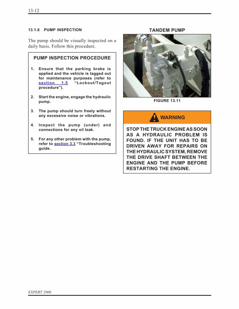
WARNING
STOP THE TRUCK ENGINE AS SOONAS A HYDRAULIC PROBLEM ISFOUND. IF THE UNIT HAS TO BEDRIVEN AWAY FOR REPAIRS ONTHE HYDRAULIC SYSTEM, REMOVETHE DRIVE SHAFT BETWEEN THEENGINE AND THE PUMP BEFORERESTARTING THE ENGINE.
13.1.6 PUMP INSPECTION
The pump should be visually inspected on adaily basis. Follow this procedure.
PUMP INSPECTION PROCEDURE
1. Ensure that the parking brake isapplied and the vehicle is tagged outfor maintenance purposes (refer tosection 1.5 “Lockout/Tagoutprocedure”).
2. Start the engine, engage the hydraulicpump.
3. The pump should turn freely withoutany excessive noise or vibrations.
4. Inspect the pump (under) andconnections for any oil leak.
5. For any other problem with the pump,refer to section 3.3 “Troubleshootingguide.
FIGURE 13.11
TANDEM PUMP

13-13
COOL HAND AUTOMATED ARM
PUMP EMERGENCY SHUTDOWNPROCEDURE
1. Press on the nearest Emergency StopButton (figure 13.13).
2. Turn the pump switch “OFF” and stopthe truck engine.
3. Close the main hydraulic valve on thesuction line near the tank(figure 13.12).
4. Call the maintenance facility and reportthe problem to the maintenancepersonnel.
5. Before restarting the engine, makesure that the pump is being properlyprimed and the main valve on thehydraulic tank is open.
6. If not possible, remove the drive shaftbetween the engine and the pump.
13.1.7 PUMP EMERGENCY SHUTDOWN
If a major problem occurs with the arm or thehydraulic system, or in the case of hydraulichose failure, apply the following procedure:
MAIN VALVE
SUCTION LINE
FIGURE 13.12
CURBSIDE VIEW,UNDER THE HOPPER
FIGURE 13.13
EMERGENCYSTOP BUTTON
WARNING
STOP THE TRUCK ENGINE AS SOONAS A HYDRAULIC PROBLEM ISFOUND. IF THE UNIT HAS TO BEDRIVEN AWAY FOR REPAIRS ONTHE HYDRAULIC SYSTEM, REMOVETHE DRIVE SHAFT BETWEEN THEENGINE AND THE PUMP BEFORERESTARTING THE ENGINE.

EXPERT 2000
13-14
13.1.8 PUMP PRIMING PROCEDURE
To prevent cavitation or air in the hydraulicsystem after installing a new pump or afterreplacing the oil in the hydraulic system, makesure to prime the pump before starting theengine. Apply the following procedure to primethe pump.
FIGURE 13.14
DANGER
APPLY THE “LOCKOUT/TAGOUT”PROCEDURE AT ALL TIMES.
DRAIN HOSE
HYDRAULIC PUMPPRIMING PROCEDURE
1. Apply the lockout/tagout procedure.
2. Secure the area around the path of thearm at all times.
3. To avoid any oil spill when working onthe pump or prior to any service job,slowly remove the oil filler cap of thehydraulic tank to release the pressureinside the tank.
4. Make sure that the main valve on thesuction line is closed.
5. Remove the drain hose from on pumphousing (figure 13.14).
6. Fill the pump housing with the properhydraulic oil.
7. Open the main valve on the tanksuction line (figure 13.12).
8. Reinstall the drain hose on the pumphousing.
9. Reinstall the filler cap and allow thepressure to rise inside the tank.
10. Check that the air pressure on theregulator gage found inside thechassis frame rail (figure 13.8).
11. Crank the engine without letting it startrepeatedly about five times in order tofill the suction hose and the pump withhydraulic oil and to push the air backinto the tank.
12. Before putting the vehicle back inservice, recalibrate the systempressure according to section 13.2“Hydraulic pressure adjustment”.

13-15
COOL HAND AUTOMATED ARM
13.2 HYDRAULIC PRESSUREADJUSTMENT
13.2.1 VANE PUMP RELIEF VALVEADJUSTMENT
The tandem pump has its own relief valve(figure 13.16). The pressure chart below givesthe proper adjustment pressure of both 22 and29/34 cubic yard bodies. Use this chart toadjust the relief of the pump and the bodyfunction valve. A 0-4000 pressure gage(figure 13.15) as well as a set of ball-end Hexkey (figure 13.17) is required to perform thispressure adjustment procedure.
Note:The relief valve of the vane pump has to setbefore the main relief valve on the directionalcontrol valve.
FIGURE 13.16
0-4000 PSI PRESSUREGAGE
(HYF00910)
QUICK CONNECT(HYF10195)
VANE PUMPRELIEF VALVE
FIGURE 13.15
PRESSURE CHART FOR 22 CU.YD BODYor 4-inch dia. packer cylinders
1. Vane pump relief valve is set at 2200PSI at 1500 RPM.
2. The main relief valve is set at 2000PSI at 1500 RPM.
PRESSURE CHART FOR 29/34 CU.YD BODYor 4-inch dia. packer cylinders
1. Vane pump relief valve is set at 3200PSI at 1500 RPM.
2. The main relief valve is set at 3000PSI at 1500 RPM.
Ball-end Hex Key (Metric & SAE)
FIGURE 13.17

EXPERT 2000
13-16
VANE PUMP RELIEF VALVEADJUSTMENT PROCEDURE
1. Apply the lockout/tagout procedure.
2. Ensure safety around the vehicle at alltimes.
3. Install the 0-4000 PSI pressure gageon the quick connect fitting located onthe body functions valve (figure 13.18).
4. Start the engine and engage thehydraulic system (Pump switch “ON”).
5. Engage the speed-up system. Theengine must be running at 1500 RPM.
6. Tighten the main relief valveadjustment screw (figure 13.19) to beable to adjust the vane pump.
7. Activate the crusher panel until thecylinder reaches the end of its stroke(Going up).
8. Adjust the relief valve of the vane pump(figure 13.20) according to thepressure chart.
9. When the vane pump is adjusted tothe proper pressure, calibrate the reliefof the body function valve accordingto the pressure chart.
MAIN RELIEF VALVEADJUSTMENT
CRUSHER PANELCONTROL LEVER
13.2.1 VANE PUMP RELIEF VALVE (cont’d)
Apply the following procedure in order toadjust the relief valve of the vane pump.
FIGURE 13.18
FIGURE 13.19
FIGURE 13.20
VANE PUMPRELIEF VALVE

13-17
COOL HAND AUTOMATED ARM
13.2.2 PISTON PUMP ADJUSTMENT
As described in section 13.1.3, the pistonpump delivers its flow only on demand (whenthe joystick is moved). The compensator,located on the pump (figure 13.22), controlsboth the pressure output and the load sensingsystem of the piston pump.
How it works:
The load sense port on the proportional valveor LS port (figure 13.21), allows pressurefrom the valve to return to the compensator,creating a margin pressure of 450 PSI betweenthe PP port and the LS port. When moving thejoystick, the pressure on the LS port will buildup, creating the demand to the piston pump.
At that point, the compensator will increasethe pump flow, keeping the pressure 450 PSIabove the pressure of the load sense port.
If a pressure of 2000 PSI is required to lift acart, the pressure at the PP port will be 2450PSI. A differential pressure of 450 PSI. Whenthere is no demand, the pressure at the port LSwill drop to 0 PSI.
Note:The port PP should always indicate 450 PSI.
The pressure adjustments of the pumpcompensator and the proportional valve haveto be made, following the right sequence.
Two pressure gages (0-4000) are necessary toperform this adjustment. One connected to thepressure port (PP) and the other on the loadsense port (LS). See figure 13.23.
The procedure on the next page will show howto adjust the load sense and the pump maximumoutput pressure.
FIGURE 13.21
PROPORTIONAL VALVE
LS
PP
(To compensator)(From the
piston pump)
FIGURE 13.22
0-4000 PSIPRESSURE GAGE
(HYF00910)
QUICK CONNECT(HYF10195)
FIGURE 13.23
PISTONPUMP
COMPENSATOR

EXPERT 2000
13-18
DANGER
DANGER
LOAD SENSE ADJUSTMENT
1. Apply the lockout / tagout procedure.
2. Before making any adjustments,secure the area around the path of thearm.
3. Remove all residual hydraulicpressure in the system by moving themanual levers back and forth.
4. Make sure that all hoses are tight andnot leaking.
5. Connect one gage to the load senseport (LS) and the second one to thepressure port (PP).
6. Put the transmission in Neutral.
7. Start the engine, and engage thehydraulic pump.
8. The pressure port gage (PP) shouldindicate 450 PSI and the load sense(LS) 0 PSI. If the pressure does notcorrespond, loosen the lock nut (figure13.24) and turn the adjustment screwto adjust the pressure to 450 PSI.
9. To adjust the load sensing pressure,the load sense screw on thecompensator may need to be turnedin or out according to the reading onthe pressure gage.
10. Recheck the pressure and tighten thelock nut in place while holding theadjustment screw.
11. Verify that the arm is working properlywith the manual levers on the valve.
13.2.3 LOAD SENSE PRESSUREADJUSTMENT
DO NOT STAND DIRECTLY IN THEPATH OF THE ARM WHILECARRYING OUT THESEADJUSTMENTS.
APPLY THE “LOCKOUT/TAGOUT”PROCEDURE AT ALL TIMES.
COMPENSATOR
FIGURE 13.24
LOAD SENSEADJUSTMENT
SCREW
Note:If the arm is moving erratically orintermittently, the presence of air in the systemmay be the cause.
Note:In the case where a new pump is installed onthe vehicle, the compensator screw must beloosened completely to prevent any damage tothe hydraulic system and its component.

13-19
COOL HAND AUTOMATED ARM
DANGER
13.2.4 PISTON PUMP PRESSUREADJUSTMENT
Apply the following procedure to calibrate thepiston pump pressure.
INNER BOOM RELIEF VALVEADJUSTMENT PROCEDURE
1. Using the lever on the proportionalvalve, retract the outer boom.
2. Raise the inner boom and hold thelever in order to read the “inner boomup” pressure on PP gage.
3. Adjust the work port at 3000 PSI, andthen add 1/4 of a turn to the screw(figure 13.26).
4. Lower the inner boom and hold thelever in order to read the “inner boomdown” pressure on PP gage.
5. Adjust the inner boom work port at2100 PSI (figure 13.26).
APPLY THE “LOCKOUT/TAGOUT”PROCEDURE AT ALL TIMES.
COMPENSATOR ADJUSTMENTPROCEDURE
1. Apply the lockout / tagout procedure.
2. Secure the area around the path of thearm.
3. Remove all residual hydraulicpressure by moving the levers backand forth.
4. Make sure that all hoses are tight andnot leaking.
5. Connect one gage to the load senseport (LS) and the second one to thepressure port (PP).
6. Put transmission in Neutral;
7. Start the engine, and engage thehydraulic pump.
8. The pressure port gage (PP) shouldindicate 450 PSI and the load sense(LS) 0 PSI. If the pressure does notcorrespond, adjust the load sensepressure first (section 13.2.3).
9. Using the lever on the proportionalvalve, retract the outer boom.
10. Raise the inner boom and hold thelever in order to read the pressure onthe PP gage.
11. Loosen or tighten the compensatorscrew to adjust the pressure on thegage on PP port to 2800 PSI (See tableon next page).
COMPENSATOR
FIGURE 13.25
COMPENSATORADJUSTMENT SCREW
13.2.5 INNER BOOM RELIEF VALVE

EXPERT 2000
13-20
1. PROPORTIONAL VALVE MAIN RELIEF (Cracking): .............................................. 3300 PSI*(Factory adjusted)
2. PISTON PUMP COMPENSATOR: ............................................................. 2800 PSI (Gage PP)
3. LOAD SENSE PRESSURE ADJUSTMENT: .......... 450 PSI (Gage PP) and 0 PSI (Gage LS)
4. GRABBER RELIEF VALVE (OPENED/CLOSED): ................................... 1800 PSI (Gage PP)
5. INNER BOOM RELIEF VALVE (ARM UP): ............................................ 3000 PSI (Gage PP)**
6. INNER BOOM RELIEF VALVE (ARM DOWN) .......................................... 2100 PSI (Gage PP)
AUTOMATED ARM PRESSURE CHART (For PV25/PV29 pump at Idle speed)
PROPORTIONAL VALVE
LSPP
OUTER BOOM
INNER BOOM
GRABBER
MAINRELIEF
* The calibration of the main relief valve requires a flow meter. It is not recommended toadjust it since the calibration was done by the manufacturer of the valve.
** Add 1/4 of turn to the adjustment screw
GRABBERCLOSE RELIEF
INNER BOOMDOWN RELIEF
INNER BOOMUP RELIEF
GRABBEROPEN RELIEF
FIGURE 13.26

13-21
COOL HAND AUTOMATED ARM
DANGER
13.2.7 CYLINDER CUSHION ADJUSTMENT
The inner and outer boom cylinders are bothcushioned on their extension and retractionstrokes. The cushioning system slows downthe speed of the cylinder at the end of thestroke to allow smooth movements whenhandling carts.
Note:For vehicle equipped with the Auto-dumpfeature, this section does not apply. Refer toEasy Supervisor User Guide.
The cushioning system is factory adjusted.However, the cushioning effect may bemodified at two levels: the range and thespeed.
By moving the proximity switches in theirmounting brackets (figure 13.27), cushionswill be active at a different position and for alonger (or shorter) distance in the cylindersstrokes.
DO NOT STAND DIRECTLY IN THEPATH OF THE ARM WHILECARRYING OUT THESEADJUSTMENTS.
13.2.6 GRABBER PRESSUREADJUSTMENT
GRABBER RELIEF VALVEADJUSTMENT PROCEDURE
1. Fully extend the arm.
2. Using the lever on the proportionalvalve, close the grabber and hold thelever in place in order to keep and readthe pressure on the PP gage.
3. Adjust the “close grabber” work portat 1800 PSI.
4. Open the grabber and adjust thepressure of the “open grabber” workport also at 1800 PSI.
FIGURE 13.27
BRACKET
PROXIMITYSWITCHES
Continued on next page. . .

EXPERT 2000
13-22
PROXIMITY SWITCHESADJUSMENT PROCEDURE
1. For each of the proximity switches (1to 4), place the cylinder rod at distanceDx (see figure 13.30 to 13.33).
2. Loosen and move the proximity switchin its bracket until the red light shutsoff at this specific position. This willmark the beginning of the cushion.
3. Tighten the proximity switch in placeand repeat for every proximity switch.
FIGURE 13.28
FIGURE 13.29
1
2
4
3
3: OUTER BOOM EXTEND* ................................... (Dx3)4: OUTER BOOM RETRACT* ................................ (Dx4)
DANGER
DANGER
DO NOT STAND DIRECTLY IN THEPATH OF THE ARM WHILECARRYING OUT THESEADJUSTMENTS.
APPLY THE “LOCKOUT/TAGOUT”PROCEDURE AT ALL TIMES.
The word “extension” and “retraction” referonly to the cylinder movement and not themovement of the arm itself.
1: INNER BOOM RETRACT* .................................. (Dx1)2: INNER BOOM EXTEND* .................................... (Dx2)
*
13.2.7 CYLINDER CUSHION ADJUSTMENT(cont’d)
Proximity switches detect the presence ofmetal. When metal is detected, the red pilotlight on the proximity switches turns “OFF”and the arm starts to slow down.
The first red light that shuts off marks thebeginning of a cushion. (A red light on eachproximity switches corresponds to “no cushionsignal”). Therefore, the arm is moving fasterwhen the red lights are “ON”.
The position of each proximity switch on themounting brackets will determine where thecushioning will start. Two pairs of proximity
switches are required to control the cushioningsystem of the arm. Each pair controls eitherthe retract or the extend cushion of a cylinder.
To adjust the proximity switches werecommend to use the following procedure:

13-23
COOL HAND AUTOMATED ARM
FIGURE 13.30
Inner boom extend(Proximity switch #2)
Dx2=18” 3/4
Inner boomcylinder
FIGURE 13.32
Inner boom retract(Proximity switch #1)
Dx1 = 4” 1/8
inner boomcylinder
FIGURE 13.31
FIGURE 13.33
Dx3=13” 1/8 Dx4=3” 7/8
Outer boom extend(Proximity switch #3)
Outer boom retract(Proximity switch #4)
Outer boomcylinderOuter boom
cylinder

EXPERT 2000
13-24
13.2.7 CYLINDER CUSHION ADJUSTMENT(cont’d)
Located inside the console, two electronicmodules control the speed or amount of cushionfor the outer and the inner boom cylinders. Oneach module, there are screws for cushionspeed adjustment (figure 13.34). It is notrecommended to change the adjustment ofthe cushions since they were adjusted at thefactory.
However, if the arm does not reach or hits therubber bumper too hard, it is possible to reduce(or increase) the speed of the cylinder cushion.Perform the following procedure for cushionadjustment:
CUSHION SPEEDADJUSTMENT PROCEDURE
1. Secure the area around the path of thearm.
2. Start the engine and engage thehydraulic system.
3. Clearly identify the cylinder cushionthat needs to be adjusted and thecorresponding module.
4. Move the joystick slowly to the desiredposition in order to bring the cylinderat the beginning of the cushion range(distance Dx), At that point, the redpilot light shall turn “OFF”.
5. Release the joystick and make surethat the proximity switch light is “OFF”.
6. Move the joystick again in the samedirection to evaluate the speed of thearm. The arm cylinder should reachthe end of its stroke without knocking.If not, increase the amount of cushion(reduce the speed).
NOTE:The word “extension” and “retraction” referonly to the cylinder movement and not themovement of the arm itself.
DANGER
DANGER
DO NOT STAND DIRECTLY IN THEPATH OF THE ARM WHILECARRYING OUT THESEADJUSTMENTS.
APPLY THE “LOCKOUT/TAGOUT”PROCEDURE AT ALL TIMES.
The screw on the cushion module may beturned clockwise or counterclockwisedepending on what result is required.
The cushion’s speed adjustment is made bystep of one quarter (1/4) of a turn at a time. Seefigure 13.34 for proper way to increase ordecrease the amount of cushion as it is not thesame way for each screw).
Increasing the amount of cushion will result inreducing the speed of the arm in the cushionrange. Decreasing the amount of cushion willresult in faster arm speed in the cushion range.

13-25
COOL HAND AUTOMATED ARM
OUTER BOOM INNER BOOM
EXTENSION(PROX. #4)
RETRACTION(PROX #3)
EXTENSION(PROX #1)
RETRACTION(PROX #2)
SIDE VIEW FRONT VIEW
REST POSITIONIN HOPPER SECTION
INNER BOOM DOWN(Joystick @ 12 O’clock)
OUTER BOOMEXTEND
(Joystick @ 3 O’clock)
INNER BOOMUP
(Joystick @ 6 O’clock)
OUTER BOOMRETRACT
(Joystick @ 9 O’clock)
CUSHIONING MODULE
FIGURE 13.34
FIGURE 13.35
INCREASE CUSHION
INCREASE CUSHION
DECREASE CUSHION
DECREASE CUSHION
ADJUSTMENTSCREW
Part #ELC12000

EXPERT 2000
13-26
13.2.8 ARM SPEED ADJUSTMENT
The arm speed is controlled by the amount ofhydraulic fluid that is being sent to the arm’scylinder. The arm control valve spools can letthrough 6 to 10 gallons per minute of hydraulicoil, depending on the section of the valve*.The flow is limited by a mechanical movementrestrictor or stopper (figure 13.36).
Note:No arm speed adjustment is required unlessreplacing the valve or a section of it.
MOVEMENT RESTRICTOR
Outer boom (10.2 G.P.M)
Inner Boom (10.2 G.P.M)
Grabber (6.6 G.P.M)
ARM CONTROL VALVE
ARM SPEEDADJUSTMENT PROCEDURE
1. Secure the area around the path of thearm.
2. Start the engine and engage thehydraulic system.
3. Clearly identify the stopper screw onthe valve that corresponds to theproper function (boom extension/retraction, grabber open/close). Movethe lever to evaluate the speed of thearm then release the lever.
4. Loosen the lock nut.
5. Screw in the restrictor adjustment onlyone eighth (1/8th) of a turn at a time tosee a significant change of the arm’sspeed.
6. Move the lever again to evaluate thearm’s speed. Repeat until satisfactory.
7. Tighten the lock nut.
NOTE:The cushioning system is not functioning whenusing manual control levers.
* Limiting the stroke of the spools is limitingthe amount of oil (flow) going through them.Controlling the flow of oil means controllingthe speed of the arm.
DANGER
DANGER
DO NOT STAND DIRECTLY IN THEPATH OF THE ARM WHILECARRYING OUT THESEADJUSTMENTS.
APPLY THE “LOCKOUT/TAGOUT”PROCEDURE AT ALL TIMES.
FIGURE 13.36

13-27
COOL HAND AUTOMATED ARM
13.2.9 OUTER BOOM RESTRICTORADJUSTMENT
The outer boom cylinder is equipped with anadjustable restrictor on the rod side (extension).The restrictor (figure 13.37) prevents theweight of the arm to pull the cylinder fasterthan the oil pressure.
RESTRICTOR ADJUSTMENTPROCEDURE
1. Secure the area around the path of thearm.
2. Engine at idle speed: 750-800 RPM.
3. Maintain the crusher panel up to warmup the hydraulic oil (10-15 minutes).Release the crusher panel thenactivate the packer blade so the oilgoes through the whole system.Repeat this operation until the oiltemperature reaches 150 0F.
4. Position the arm as shown in figure13.38.
5. Unlock the restrictor knob byloosening the hex key lock screw.
6. Screw-out the restrictor knob.
7. Extend and retract the outer boomseveral times. At one point, whileextending the outer boom, the weightof the outer pulls faster on the cylinderthan the flow coming from the pump.The arm slows down and goes againwhen the flow reaches the cylinder.
8. Screw-in the restrictor until the pumpalone forces the extension of thecylinder and you obtain a steadypendulum motion.
9. Do not over screw the restrictor, sincethe restriction has to be at theminimum, so the arm speed and the oiltemperature are not affected.
10. Once properly adjusted, lock therestrictor knob in place using the hexkey lock screw.
FIGURE 13.37
FIGURE 13.38
RESTRICTORKNOB
LOCKSCREW

EXPERT 2000
13-28
INNER BOOM LOCK VALVEADJUSTMENT PROCEDURE
1. Secure the area around the path of thearm.
2. Start the engine and engage thehydraulic system.
3. Operate the inner boom to ensure noair is in the hydraulic system.
4. Retract the inner boom cylinder toone-third of its stroke (Inner boomdown), then extend the outer boomcylinder to full reach.
5. Loosen the locknut on the cartridge ofthe lock valve (figure 13.39).
6. With the pump switch turned off,tighten the adjustment screw until theinner boom starts to fall under it’s ownweight (The inner boom may start toshake when loosening too much).
7. Then return the screw back in until theinner boom just stops falling. Pick upa weight of 450 lbs to the grabber andcheck if the inner boom goes furtherdown. If the inner boom falls, loosenthe adjustment screw until it stops.
8. Once properly adjusted tighten thelocknut of the adjustment screw.
FIGURE 13.39
13.2.10 INNER BOOM LOCK VALVEADJUSTMENT
IMPORTANT:Throughout this procedure: the inner boomcylinder must not bottom out. Use onlyhydraulic power to raise the inner boom.
DANGER
DANGER
DO NOT STAND DIRECTLY IN THEPATH OF THE ARM WHILECARRYING OUT THESEADJUSTMENTS.
APPLY THE “LOCKOUT/TAGOUT”PROCEDURE AT ALL TIMES.
HOLDINGVALVE

13-29
COOL HAND AUTOMATED ARM
13.2.11 GRABBER LOCK VALVEADJUSTMENT
The purpose of this lock valve is to lock the oilinside the cylinder so no oil can come out oneither side of it. This situation will remainuntil enough flow or pressure is sent in againto move the cylinder.
This feature ensures that once the grabber isclosed on a roller cart, it will remain that wayand will not close any further or open untilanother hydraulic signal (like open or closethe grabber) is sent. No maintenance oradjustment is required on the lock valve.
In case the grabber fails to hold onto carts,remove and clean the valve or replace it
FIGURE 13.40
FIGURE 13.41
DANGER
DANGER
DO NOT STAND DIRECTLY IN THEPATH OF THE ARM WHILECARRYING OUT THESEADJUSTMENTS.
APPLY THE “LOCKOUT/TAGOUT”PROCEDURE AT ALL TIMES.
GRABBERLOCK VALVE
GRABBERLOCK VALVEGRABBER

EXPERT 2000
13-30
DANGER
DO NOT EXCEED A PRESSURE OF5 PSI WHEN ADJUSTING THE AIRREGULATOR. KEEP THE SAFETYVALVE AND THE FILLER CAPCLEAN AND TAKE EXTREMEPRECAUTION WHEN OPENING THEFILLER CAP.
FIGURE 13.42
FIGURE 13.43
FIGURE 13.44
13.2.12 PRESSURIZED HYDRAULIC TANK
To make sure the pump is properly fed with oiland to prevent any cavitation, the hydraulictank is pressurized with air.
The air from the brake system of the truck isbeing used for this purpose. The pressure hasto be brought down around 3 to 3.5 PSI withthe use of an air pressure regulator(figure13.44).
Then the air pressure enters the hydraulic tankfrom the top and presses down on the hydraulicoil to feed the pump. To prevent any pressurebuilt up, a safety relief valve set to PSI is beingused. The filler cap will also vent any airpressure higher than 5 PSI.
PRESSUREREGULATOR
PRESSURE GAGE
5 PSIFILLER CAP
5 PSI RELIEFVALVE

13-31
COOL HAND AUTOMATED ARM
13.3 ELECTRICAL SYSTEMS
13.3.1 ELECTRICAL SYSTEM GENERALDESCRIPTION
The automated side loader units use the sameelectrical system for the body and cab controlsas the standard Expert 2000 unit, except thewiring of the auto-neutral system(See section 13.3.4).
Also, the automated arm has a separate wiringsystem. A combination of different color-codedwiring harnesses, ensure the proper electricalcommunication between the joystick, the armcomputer (cushioning module) and thehydraulic control valve.
Most of the electrical components are locatedin the console. A sealed packer control modulelocated at the front of the body and can beaccessed through a removable access door(figure 13.45).
PACKER ELECTRONIC MODULE
1: ACCESS DOOR FOR PACKERMODULE
2: PACKER CONTROLS(optional on left-hand side)
2
1
FIGURE 13.45
13.3.2 ELECTRICAL SCHEMATICS
Refer to the main electrical schematic found alittle plastic bag inside the console(figure 13.46).
For every truck configuration, a differentschematic is being used. Therefore, the electricalschematics found the special pocket of thismanual and in the console are specific to thetruck. Those schematics are numbered in thebottom right corner. To help trace back theproper schematic going with a specific truck, asticker with schematic number is applied on theinside wall of the console.
FIGURE 13.46
ELECTRICALSCHEMATICS

EXPERT 2000
13-32
13.3.3 ALLISON TRANSMISSIONPROGRAMMING PARAMETERS
The Allison transmission electronic controlunit (ECU) controls several systems of theautomated unit; it prevents pump from overspeeding (2300 RPM maximum). The ECUalso prevents the pump engagement if theengine speed is any higher than 900 RPM. Itwill also shut off the pump and the joystick (ofthe arm) if the vehicle is moving faster than15 MPH (25Km/h). The transmission ECUalso controls the auto-neutral system.
If the vehicle requires having the ECU repairedor replaced, or a specific programmingparameters, refer to section 3.17 “AllisonTransmission Programming Parameters”.
A “Pro-link” keypad interface (figure 13.47)may be used to program the Allison ECU andverify if the signals are properly reaching thecomputer and verify the fault code. To tap ontothe ECU, Labrie uses the following wires onthe Allison connector:
INPUT:
#117: PUMP PACK ENABLE: Active whenthe brakes are used, and when the PTOand auto-neutral switch is“ON”(ground signal).
#118: PTO ENABLE: Active when the PTOswitch is “ON”(+12V. signal).
#153: AUTO-NEUTRAL PACK INPUT:Active when the brakes are used, andwhen the PTO and auto-neutral switchesare “ON” (ground signal).
OUTPUT:
#112: PTO ENABLE OUTPUT: Active whenthe PTO switch is “ON” and when allengine and vehicle speed criteria arerespected (+12V. signal). Refer to theprogramming parameter chart,section 3.17 “Allison TransmissionProgramming Parameters” in theTroubleshooting section of the Partsand Service manual.
#114: NEUTRAL SIGNAL OUTPUT: Activewhen the transmission is in neutral. Thissignal (ground signal) is used to allowthe fast idle engagement (1500 RPM).For more details, refer to the electricalschematic.
FIGURE 13.47

13-33
COOL HAND AUTOMATED ARM
13.3.4 AUTO-NEUTRAL SYSTEM
The Auto-neutral switch allows thetransmission to shift from “DRIVE” to“NEUTRAL” automatically without using theshifter lever or shifter keypad.
When the operator stops the vehicle and appliesthe temporary handbrake, a signal is sent totransmission computer (ECU) to automaticallyshift the transmission to “NEUTRAL”.However, the transmission will not shift backto “DRIVE” automatically when releasing thetemporary handbrake; the operator must pressthe footbrake pedal to shift back to “DRIVE”
Also, when the Auto-neutral switch is set to“ON”, the transmission will automatically shiftto NEUTRAL as soon as the operator pressesthe footbrake pedal (without activating thetemporary handbrake).
30 PSI of air is required at the brake pedal toactivate the Auto-neutral. This means that amedium pressure of the foot on the brake pedalis sufficient to activate the Auto-neutral andshift the transmission to “NEUTRAL”. Whenreleasing the brake pedal, the transmissionwill shift back to “DRIVE” automatically.
FIGURE 13.49
FOOTBRAKEPRESSURE SWITCH
Pressure switches (figure 13.48) are installedon the footbrake pedals. The one installed onthe right-hand side, is found in the cab behindthe pedal (figure 13.49). The one on the left-hand side is accessible from the enginecompartment mounted on the firewall(figure 13.50). A third pressure switch islocated behind the temporary handbrake toggleswitch (figure 13.51).
Pressure switch on the right-handside driving position
Continued on next page . . .
Pressure switch
FIGURE 13.48

EXPERT 2000
13-34
PRESSURESWITCH
FIGURE 13.50
Pressure switch on the enginecompartment
13.3.4 AUTO-NEUTRAL SYSTEM (Cont’d)
The pressure switches found on the footbrake(PNI00605) are adjustable but were calibratedat 30 PSI from the factory and do not requiredfurther adjustment. The pressure switch forthe temporary handbrake (PNI00600) is fixedand it is set to operate at 55PSI.
FIGURE 13.52
PRESSURE SWITCH(Temporary handbrake light)
FIGURE 13.51
TEMPORARYHANDBRAKE PANEL
PRESSURE SWITCH(Auto-Neutral)
Pressure switch behindtemporary handbrake

13-35
COOL HAND AUTOMATED ARM
AUTO NEUTRAL TROUBLESHOOTING SCHEMATICS
FIGURE 13.53
Z379
80

EXPERT 2000
13-36
13.4 TROUBLESHOOTING GUIDE
13.4.1 COOL HAND TROUBLESHOOTING
This troubleshooting guide will help identify the most commonly seen problems on the Coolhand Automated Arm. It will also provide the possible cause of a problem and give possiblesolutions to resolve the problem. This guide applies only to the Cool Hand section of the unit.For further information regarding the body or other problems that might occur, refer to the bodytroubleshooting guide found in section 3 of this manual or contact the Labrie Technical Supportservice.
• The arm is too fast.
• The arm is too slow.
1.The proximity switches are faultyor misplaced on bracket mount;
2.Power cables are cut off ordefective;
1.Wrong pressure setting;
2.Restrictors on the DANFOSSvalve hold too tight;
1.Wrong hydraul ic pressuresetting;
2.Restrictors on the DANFOSSvalve hold too tight;
3.No signals from the proximityswitches;
4.Faulty proximity switches;
1.Position the proximity switch onbracket mount (Seesection 13.2.7 “Cylinder cushionadjustment”);
2.Change faulty proximity switchesand/or cables;
1.Re-calibrate the pressure setting(see section 13.2 “Hydraulicpressure adjustment”);
2.Re-calibrate cylinder’s speed(see section 13.2.8 “Arm speedadjustment”);
1.Re-calibrate the pressure setting(see section 13.2 “Hydraulicpressure adjustment”);
2.Re-calibrate cylinder’s speed(see section 13.2.8 “Arm speedadjustment”);
3.Check for incoming signals fromthe proximity switches (Seesection 13.4.2 “Proximity switchsignal checking procedure”);
4.Change faulty proximity switchesand or cables;
SOLUTIONPOSSIBLE CAUSES
SOLUTIONPROBLEMS POSSIBLE CAUSES
SOLUTIONPROBLEMS POSSIBLE CAUSES
PROBLEMS
• The cushion’s distance isinsuff ic ient or too long.(Without Smart-Hand feature)

13-37
COOL HAND AUTOMATED ARM
• Flashing lights on dashboardare always blinking. (WithoutSmart-Hand feature)
• The arm does not respond tojoystick (Assuming that PTOswitch and light are On).(Without Smart-Hand feature).
1.The proximity switch in thehopper section is misplaced;
2.Power cables are cut off ordefective;
3.The proximity switch is faulty.
1.Burned fuses.
2.Power cables are cut off ordefective.
3.Faulty joystick.
1.Position the proximity switch onbracket mount, aligned with themetal rod, inner boom up in thehopper section;
2.Perform a continuity test on thecable or change faulty cables;
3.Change faulty proximityswitches;
1.Check fuses in the console (6port fuse holder)
2.Check red wires (#158) on eachcushioning modules for 12 voltssupply (Move joystick to getsignals).
3.Contact customer’s services atLabrie.
13.4.1 COOL HAND TROUBLESHOOTING (cont’d)
SOLUTIONPOSSIBLE CAUSESPROBLEMS
SOLUTIONPOSSIBLE CAUSESPROBLEMS

EXPERT 2000
13-38
NOTE:For more details on the cushioning modules,refer to section 13.2.7 “Cylinder cushionadjustment”.
Wire #804 = PROX. #4
BLACK BLUE
Wire #802 = PROX. #2
OUTTERBOOM
INNER BOOM
WHITE
BLACKWire #803 = PROX. #3
Wire #801 = PROX. #1
FIGURE 13.54
13.4.2 PROXIMITY SWITCH SIGNALCHECKING PROCEDURE
SIGNALS CHECKING PROCEDURE
1. Secure the area around the path of thearm.
2. Start the engine and engage thehydraulic system.
3. With the levers installed on the armcontrol valve, bring the arm cylindersto the middle of their stroke (Inner andouter boom half extension).
4. Make sure that all the proximityswitches light are “ON“ (Red pilotlights).
5. Identify, in the console, thecorresponding cushioning module foreach proximity switches.
6. Check each wires (figure 13.54) forproper ground signals.

13-39
COOL HAND AUTOMATED ARM
13.5 HYDRAULIC SCHEMATICS (Arm section)
FIGURE 13.55
LOA
D S
EN
SIN
G
QU
ICK
CO
NN
ECT
FOR
PR
ESS
UR
E G
AUG
E
RE
TUR
N T
O T
AN
K
PR
ES
SUR
E F
RO
M T
HE
PU
MP
DAN
FOSS
VAL
VE
AU
TOM
ATE
D A
RM
HO
LDIN
G V
ALV
E
GR
AB
BER
LO
CK
VAL
VE
RES
TRIC
TOR
LS A
LS B
LS A
LS B
1
3
2

EXPERT 2000
13-40
13.6 HYDRAULIC SCHEMATIC (Body section)
FIGURE 13.55
CRUSHER PANEL
SOLENOID VALVE
TAILGATE
VELOCITY FUSE
HOLDING VALVE
TANK
PRESSURE GAUGEQUICK CONNECT FOR
FOR TEST PORTQUICK CONNECT
VELOCITY FUSE
2
WORK PORT RELIEF 1500 PSI
MAIN RELIEF VALVE 3000 PSI
1
WORK PORT RELIEF 1700 PSI

13-41
COOL HAND AUTOMATED ARM
PACKING CYLINDER
BODY HOIST
P2
VENT VALVE
LOAD SENSING TOLS
PRESSURE TO
P1
DOUBLE DENISON PUMP
DANFOSS VALVE
DANFOSS VALVECOOL HAND PUMP

EXPE
RT 2
000
13-4
2
13.7
22, 2
9, 3
4 C
U.Y
D B
OD
Y H
YDA
RU
LIC
DIA
GR
AM
FO
R C
OO
L H
AN
D13
.7.1
EXPE
RT
2000
HYD
RA
ULI
C D
IAG
RA
M, 3
000p
si s
yste
m, w
ith C
ool-H
and
Aut
omat
ed a
rm
See
det
ail “
E”
See
det
ail “
B”
See
det
ail “
C”
See
det
ail “
A”
Det
ail “
B”
Det
ail “
C”
Det
ail “
A”
Det
ail “
D”
Det
ail “
E”
See
det
ail “
F”
Det
ail “
F”
See
det
ail “
G”
Det
ail “
G”
See
det
ail “
D”
See
det
ail “
H”
Det
ail “
H”

13-4
3H
YDRA
ULI
C
13.7
22,2
9, 3
4 C
U.Y
D B
OD
Y H
YDR
AU
LIC
DIA
GR
AM
FO
R C
OO
L H
AN
D13
.7.1
EXPE
RT
2000
HYD
RA
ULI
C D
IAG
RA
M, 3
000p
si s
yste
m, w
ith C
ool-H
and
Aut
omat
ed a
rm
No.
Part
#D
escr
iptio
n Q
ty.
1H
YF06
700
Fitti
ng /
all.
......
......
......
......
......
......
......
......
......
.....
22
2500
0Pi
pe /
25 a
nd 2
9 cu
. yd.
......
......
......
......
......
......
..1
2500
0Pi
pe /
34 c
u.yd
with
tag
axle
......
......
......
......
......
..1
2546
3Pi
pe /
34 c
u.yd
with
out t
ag a
xle
......
......
......
......
...1
325
252
Pipe
/ Al
l....
......
......
......
......
......
......
......
......
......
....1
4H
YF05
400
Fitti
ng /
All.
......
......
......
......
......
......
......
......
......
....1
527
333
Pipe
/ 22
cu.
yd.
......
......
......
......
......
......
......
......
..1
2063
2Pi
pe /
29 c
u. y
d....
......
......
......
......
......
......
......
.....
144
546
Pipe
/ 34
cu.
yd.
......
......
......
......
......
......
......
......
..1
620
911
Hos
e / A
ll....
......
......
......
......
......
......
......
......
......
...1
727
321
Pipe
/ Al
l....
......
......
......
......
......
......
......
......
......
....1
825
179
Pipe
/ 22
and
29
cu. y
d....
......
......
......
......
......
.....
125
179
Pipe
/ 34
cu.
yd w
ith ta
g ax
le...
......
......
......
......
.....
125
466
Pipe
/ 34
cu.
yd w
ithou
t tag
axl
e...
......
......
......
......
19
HYF
0811
0Fi
tting
/ Al
l....
......
......
......
......
......
......
......
......
......
.110
HYF
0660
0Fi
tting
/ Al
l....
......
......
......
......
......
......
......
......
......
.111
2519
1Pi
pe /
All.
......
......
......
......
......
......
......
......
......
......
.112
HYF
0511
4Fi
tting
/ Al
l....
......
......
......
......
......
......
......
......
......
.113
3122
5Pi
pe /
22 c
u. y
d....
......
......
......
......
......
......
......
.....
120
625
Pipe
/ 29
cu.
yd.
......
......
......
......
......
......
......
......
..1
4454
7Pi
pe /
34 c
u. y
d...
......
......
......
......
......
......
......
......
114
3027
2H
ose
/ All.
......
......
......
......
......
......
......
......
......
......
115
2732
6Pi
pe /
All.
......
......
......
......
......
......
......
......
......
......
.116
HYF
0690
0Fi
tting
/ Al
l....
......
......
......
......
......
......
......
......
......
.117
2959
8Pi
pe...
......
......
......
......
......
......
......
......
......
......
......
118
2505
5Pi
pe /
25 a
nd 2
9 cu
. yd.
......
......
......
......
......
......
..1
2505
5Pi
pe /
34 c
u.yd
with
tag
axle
......
......
......
......
......
..1
2546
5Pi
pe /
34 c
u.yd
with
out t
ag a
xle
......
......
......
......
...1
19H
YF06
800
Fitti
ng /
All.
......
......
......
......
......
......
......
......
......
....2
2025
192
Pipe
/ Al
l....
......
......
......
......
......
......
......
......
......
....1
21H
YF05
300
Fitti
ng /
All.
......
......
......
......
......
......
......
......
......
....1
2231
224
Pipe
/ 22
cu.
yd.
......
......
......
......
......
......
......
......
..1
1039
5Pi
pe /
29 c
u. y
d....
......
......
......
......
......
......
......
.....
110
974
Pipe
/ 34
cu.
yd.
......
......
......
......
......
......
......
......
..1
2330
282
Hos
e / A
ll....
......
......
......
......
......
......
......
......
......
...1
2420
635
Pipe
/ Al
l....
......
......
......
......
......
......
......
......
......
....1
2524
387
Pipe
/ Al
l....
......
......
......
......
......
......
......
......
......
....1
2650
07Br
acke
t / A
ll....
......
......
......
......
......
......
......
......
.....
227
HYS
0200
Supp
ort /
All
......
......
......
......
......
......
......
......
......
..5
28H
YS03
00Su
ppor
t / A
ll...
......
......
......
......
......
......
......
......
.....
528
HYS
0400
Supp
ort /
All
......
......
......
......
......
......
......
......
......
..5

EXPE
RT 2
000
13-4
4
13.7
22, 2
9, 3
4 C
U.Y
D B
OD
Y H
YDA
RU
LIC
DIA
GR
AM
FO
R C
OO
L H
AN
D13
.7.2
PRO
POR
TIO
NN
AL
VALV
E
2 3 2
56
78
9
1
10
INN
ER B
OO
M
GR
AB
BER
OU
TER
BO
OM
4
11
13 12

13-4
5H
YDRA
ULI
C
13.7
22,2
9, 3
4 C
U.Y
D B
OD
Y H
YDR
AU
LIC
DIA
GR
AM
FO
R C
OO
L H
AN
D13
.7.2
PRO
POR
TIO
NN
AL
VALV
E
No.
Par
t #D
escr
iptio
n...
......
......
......
......
......
......
......
......
....Q
ty.
1.H
YV
0430
0-01
Pro
porti
onal
val
ve a
ssy.
......
......
......
......
......
......
......
......
......
......
....1
2.H
YF1
0200
Qui
ck c
onne
ct...
......
......
......
......
......
......
......
......
......
......
......
......
......
23.
HY
F046
90A
dapt
or u
nion
......
......
......
......
......
......
......
......
......
......
......
......
......
...2
4.27
324
Ada
ptor
90o
......
......
......
......
......
......
......
......
......
......
......
......
......
......
.15.
HY
F100
50P
rote
ctor
cap
......
......
......
......
......
......
......
......
......
......
......
......
......
....2
6.H
YV
0432
1-01
Ele
ctric
act
uato
r...
......
......
......
......
......
......
......
......
......
......
......
......
..2
7.H
YF0
5155
90o a
dapt
or...
......
......
......
......
......
......
......
......
......
......
......
......
......
....1
8.H
YV
0432
0E
lect
ric a
ctua
tor
......
......
......
......
......
......
......
......
......
......
......
......
.....
19.
HY
F049
00A
dapt
or, u
nion
......
......
......
......
......
......
......
......
......
......
......
......
......
..6
10.H
YF0
7500
90o ad
apto
r....
......
......
......
......
......
......
......
......
......
......
......
......
......
....1
11.H
YF0
9625
Ada
ptor
, uni
on...
......
......
......
......
......
......
......
......
......
......
......
......
.....
112
.HY
F090
00A
dapt
or, u
nion
......
......
......
......
......
......
......
......
......
......
......
......
......
..1
13.H
YF0
8950
Ada
ptor
, uni
on...
......
......
......
......
......
......
......
......
......
......
......
......
.....
1

EXPE
RT 2
000
13-4
6
13.7
22, 2
9, 3
4 C
U.Y
D B
OD
Y H
YDA
RU
LIC
DIA
GR
AM
FO
R C
OO
L H
AN
D13
.7.3
HYD
RA
ULI
C P
UM
P
9
43
2
8
1
1
7
5
6
11
10
12
1314
15

13-4
7H
YDRA
ULI
C
13.7
22,2
9, 3
4 C
U.Y
D B
OD
Y H
YDR
AU
LIC
DIA
GR
AM
FO
R C
OO
L H
AN
D13
.7.3
HYD
RA
ULI
C P
UM
P
No.
Part
#D
escr
iptio
n / B
ody
Cap
acity
Qty
.
1.H
YF00
080
Adap
tor
flang
e...
......
......
......
......
......
......
......
......
..2
2.H
YF00
095
Adap
tor
flang
e...
......
......
......
......
......
......
......
......
..1
3.H
YF04
850
Adap
tor,
unio
n...
......
......
......
......
......
......
......
......
..1
4.H
YF04
955
Adap
tor,
unio
n...
......
......
......
......
......
......
......
......
..1
5.H
YF13
150
90O
Pip
e ad
apto
r....
......
......
......
......
......
......
......
....1
6.H
YF13
185
Adap
tor
......
......
......
......
......
......
......
......
......
......
...1
7.H
YF14
050
Pipe
kin
g ni
pple
......
......
......
......
......
......
......
......
...1
8.H
YF25
005
90O
Ada
ptor
......
......
......
......
......
......
......
......
......
...1
9.H
YP01
500
Tand
em p
ump
(PV2
9)...
......
......
......
......
......
......
..1
10.
HYP
0155
0Sp
acer
......
......
......
......
......
......
......
......
......
......
....1
11.
HYS
0255
0Pi
pe fl
ange
......
......
......
......
......
......
......
......
......
....1
12.
HYP
0155
5C
ompe
nsat
or...
......
......
......
......
......
......
......
......
...1
13.
HYP
0156
5D
ump
valv
e...
......
......
......
......
......
......
......
......
......
114
.H
YP01
570
Plun
ger.
......
......
......
......
......
......
......
......
......
......
...1
15.
HYP
0156
0So
leno
id...
......
......
......
......
......
......
......
......
......
.....
1

EXPE
RT 2
000
13-4
8
13.8
AU
TOM
ATE
D A
RM
PA
RTS
13.8
.1A
RM
INST
ALL
ATI
ON
ON
BO
DY
21
12
32
4

13-4
9H
YDRA
ULI
C
13.8
AU
TOM
ATE
D A
RM
PA
RTS
13.8
.1A
RM
INST
ALL
ATI
ON
ON
BO
DY
No.
Part
#D
escr
iptio
n Q
ty.
1.Q
UB1
3150
Bolt
......
......
......
......
......
......
......
......
......
......
...11
2.Q
UR
0213
0W
ashe
r...
......
......
......
......
......
......
......
......
......
223.
QU
E024
00N
ut...
......
......
......
......
......
......
......
......
......
......
.11
4.BC
B002
11-0
1Au
tom
ated
arm
......
......
......
......
......
......
......
.....
1

EXPE
RT 2
000
13-5
0
13.8
AU
TOM
ATE
D A
RM
PA
RTS
13.8
.2A
RM
BA
SE A
SSEM
BLY

13-5
1H
YDRA
ULI
C
13.8
AU
TOM
ATE
D A
RM
PA
RTS
13.8
.2A
RM
BA
SE A
SSEM
BLY
No.
Part
#D
escr
iptio
n Q
ty.
1.51
513
PIVO
T...
......
......
......
......
......
......
......
......
......
......
..2
2.51
514
LIN
KAG
E R
H E
XTER
IOR
......
......
......
......
......
.....
13.
5151
8BA
SE A
SSY.
......
......
......
......
......
......
......
......
......
.14.
5165
6IN
NER
BO
OM
ASS
Y....
......
......
......
......
......
......
..1
5.BA
A015
00P
IVO
T...
......
......
......
......
......
......
......
......
......
......
..1
6.BA
A016
00P
IVO
T...
......
......
......
......
......
......
......
......
......
......
..1
7.B
AL0
1200
LIN
KA
GE
LH
EX
TER
IOR
......
......
......
......
......
......
...1
8.B
CH
0010
0P
LAIN
BU
SH
ING
......
......
......
......
......
......
......
......
....8
9.BC
H01
600
RIN
G...
......
......
......
......
......
......
......
......
......
......
....2
10.
BCH
0170
0SN
AP R
ING
......
......
......
......
......
......
......
......
......
..6
11.
BCH
0180
0BO
LT...
......
......
......
......
......
......
......
......
......
......
...4
12.
BCH
0512
5GR
EASE
FIT
TIN
G...
......
......
......
......
......
......
......
......
313
.BC
H12
500L
INKA
GE
INTE
RIO
R...
......
......
......
......
......
......
......
..2
14.
HYC
0021
6LO
WER
BO
OM
CYL
IND
ER...
......
......
......
......
......
....1
15.
QU
B450
00PL
AIN
BU
SHIN
G...
......
......
......
......
......
......
......
....4

EXPE
RT 2
000
13-5
2
13.8
AU
TOM
ATE
D A
RM
PA
RTS
13.8
.3IN
NER
BO
OM
SEC
TIO
N

13-5
3H
YDRA
ULI
C
13.8
AU
TOM
ATE
D A
RM
PA
RTS
13.8
.3IN
NER
BO
OM
SEC
TIO
N
No.
Part
#D
escr
iptio
n Q
ty.
1.51
517
PIV
OT
......
......
......
......
......
......
......
......
......
......
......
....1
2.59
858
KIT
SP
AC
ER
*...
......
......
......
......
......
......
......
......
......
1B
CH
0110
0S
PA
CE
R 0
.649
”...
......
......
......
......
......
......
......
....2
BC
H01
105
SP
AC
ER
0.6
69”
......
......
......
......
......
......
......
......
.2B
CH
0111
0S
PA
CE
R 0
.688
”...
......
......
......
......
......
......
......
....2
BC
H01
115
SP
AC
ER
0.7
08”
......
......
......
......
......
......
......
......
.2
3.B
AJ0
0200
SE
AL
......
......
......
......
......
......
......
......
......
......
......
......
24.
BA
R00
200
BE
AR
ING
......
......
......
......
......
......
......
......
......
......
....2
5.B
CH
0100
0W
AS
HE
R...
......
......
......
......
......
......
......
......
......
......
.16.
QU
E03
975
CA
STL
E N
UT
......
......
......
......
......
......
......
......
......
....1
7.Q
UP
0371
0C
OTT
ER
PIN
......
......
......
......
......
......
......
......
......
....1
8.Q
UV
0279
9S
CR
EW
......
......
......
......
......
......
......
......
......
......
......
.1
* Th
e sp
acer
kit
prov
ides
sev
eral
spa
cer t
hick
ness
es to
fill
gaps
bet
wee
n bu
shin
gs a
nd b
eari
ng. T
he g
ap m
ayva
ry fr
om o
ne s
ide
to a
noth
er; m
ake
sure
to in
stal
l the
prop
er sp
acer
to fi
ll th
e ga
p. N
ote
that
the
kit i
s des
ign
for t
his
pivo
t onl
y an
d m
ay n
ot fi
t on
othe
r piv
ots.
EXPE
RT 2
000
13-5
4
13.8
AU
TOM
ATE
D A
RM
PA
RTS
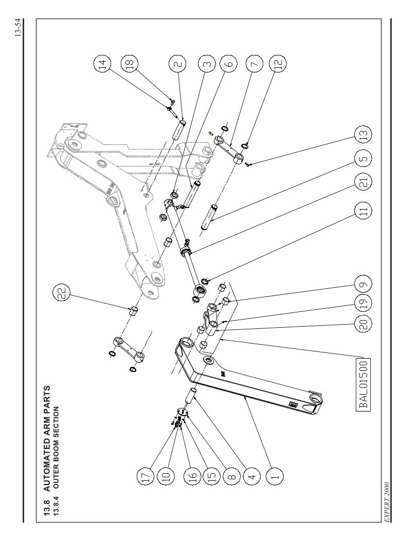
13.8
.4O
UTE
R B
OO
M S
ECTI
ON

13-5
5H
YDRA
ULI
C
13.8
AU
TOM
ATE
D A
RM
PA
RTS
13.8
.4O
UTE
R B
OO
M S
ECTI
ON
No.
Part
#D
escr
iptio
n Q
ty.
1.46
900
OU
TER
BO
OM
AS
SY
......
......
......
......
......
......
......
..1
2.51
734
PIV
OT
......
......
......
......
......
......
......
......
......
......
......
....1
3.51
735
SP
AC
ER
......
......
......
......
......
......
......
......
......
......
......
24.
BA
A01
100
PIV
OT
......
......
......
......
......
......
......
......
......
......
......
....1
5.B
AA
0140
0P
IVO
T...
......
......
......
......
......
......
......
......
......
......
......
.16.
BA
A01
500
PIV
OT
......
......
......
......
......
......
......
......
......
......
......
....1
7.B
AL0
1100
OU
TER
AR
M C
ON
NE
CTI
NG
LIN
K...
......
......
......
..2
8.B
AP
0200
0C
OV
ER
......
......
......
......
......
......
......
......
......
......
......
..1
9.B
CH
0010
0P
LAIN
BU
SH
ING
......
......
......
......
......
......
......
......
....4
10.
BC
H01
200
LOC
K W
AS
HE
R...
......
......
......
......
......
......
......
......
..2
11.
BC
H01
600
RIN
G...
......
......
......
......
......
......
......
......
......
......
......
...2
12.
BC
H01
700
SN
AP
RIN
G...
......
......
......
......
......
......
......
......
......
...4
13.
BC
H01
800
BO
LT...
......
......
......
......
......
......
......
......
......
......
......
..2
14.
BC
H02
000
EY
E B
OLT
......
......
......
......
......
......
......
......
......
......
...1
15.
BC
H02
100
LOC
K W
AS
HE
R...
......
......
......
......
......
......
......
......
..2
16.
BC
H04
305
BO
LT...
......
......
......
......
......
......
......
......
......
......
......
..2
17.
BC
H04
310
BO
LT...
......
......
......
......
......
......
......
......
......
......
......
..2
18.
BC
H04
315
BO
LT...
......
......
......
......
......
......
......
......
......
......
......
..1
19.
BC
H05
125
GR
EA
SE
FIT
TIN
G...
......
......
......
......
......
......
......
.....
320
.B
CH
1275
0IN
NE
R A
RM
CO
NN
EC
TIN
G L
INK
......
......
......
......
121
.H
YC
0020
4O
UTE
R B
OO
M C
YLI
ND
ER
......
......
......
......
......
.....
122
.Q
UB
4500
0P
LAIN
BU
SH
ING
......
......
......
......
......
......
......
......
....2

EXPE
RT 2
000
13-5
6
13.8
AU
TOM
ATE
D A
RM
PA
RTS
13.8
.5H
OR
IZO
NTA
L B
OO
M

13-5
7H
YDRA
ULI
C
13.8
AU
TOM
ATE
D A
RM
PA
RTS
13.8
.5H
OR
IZO
NTA
L B
OO
M
No.
Part
#D
escr
iptio
n Q
ty.
1.51
517
PIV
OT
......
......
......
......
......
......
......
......
......
......
......
....1
2.51
543
SP
AC
ER
......
......
......
......
......
......
......
......
......
......
......
13.
5979
8H
OR
IZO
NTA
L B
OO
M A
SS
Y...
......
......
......
......
......
14.
5985
6K
IT S
PA
CE
R B
RA
SS
......
......
......
......
......
......
......
...1
BC
H04
005
SP
AC
ER
0.0
39”.
......
......
......
......
......
......
......
..1
BC
H04
010
SP
AC
ER
0.0
78”.
......
......
......
......
......
......
......
..1
5.59
857
KIT
SP
AC
ER
......
......
......
......
......
......
......
......
......
.....
1B
AC
0110
0S
PA
CE
R 0
.649
”....
......
......
......
......
......
......
......
....
2B
AC
0110
5S
PA
CE
R 0
.669
”....
......
......
......
......
......
......
......
....
2B
AC
0111
0S
PA
CE
R 0
.688
”....
......
......
......
......
......
......
......
....
2B
AC
0111
5S
PA
CE
R 0
.708
”....
......
......
......
......
......
......
......
....
2B
AC
0112
0S
PA
CE
R 0
.748
”....
......
......
......
......
......
......
......
....
2
6.B
AC
0120
0S
PA
CE
R...
......
......
......
......
......
......
......
......
......
......
...2
7.B
AJ0
0100
SE
AL
......
......
......
......
......
......
......
......
......
......
......
......
28.
BA
R00
100
BE
AR
ING
......
......
......
......
......
......
......
......
......
......
....2
9.B
CH
0090
0S
PA
CE
R...
......
......
......
......
......
......
......
......
......
......
...1
10.
BC
H01
000
WA
SH
ER
......
......
......
......
......
......
......
......
......
......
....1
11.
BC
H03
600
NU
T...
......
......
......
......
......
......
......
......
......
......
......
...2
12.
BC
H04
330
BO
LT...
......
......
......
......
......
......
......
......
......
......
......
..2
13.
BC
H04
900
PLA
IN B
US
HIN
G...
......
......
......
......
......
......
......
......
.114
.B
CH
0500
0P
IVO
T LI
NK
AS
SY
.....
......
......
......
......
......
......
......
..1
15.
BC
H05
125
GR
EA
SE
FIT
TIN
G...
......
......
......
......
......
......
......
.....
116
.Q
UE
0397
5C
AS
TLE
NU
T...
......
......
......
......
......
......
......
......
......
.117
.Q
UP
0371
0C
OTT
ER
PIN
......
......
......
......
......
......
......
......
......
....1
18.
QU
V02
799
SC
RE
W...
......
......
......
......
......
......
......
......
......
......
....1
* Th
e sp
acer
kit
prov
ides
sev
eral
spa
cer t
hick
ness
es to
fill
gaps
bet
wee
n bu
shin
gs a
nd b
eari
ng. T
he g
ap m
ayva
ry fr
om o
ne s
ide
to a
noth
er; m
ake
sure
to in
stal
l the
prop
er sp
acer
to fi
ll th
e ga
p. N
ote
that
the
kit i
s des
ign
for t
his
pivo
t onl
y an
d m
ay n
ot fi
t on
othe
r piv
ots.

EXPE
RT 2
000
13-5
8
13.8
AU
TOM
ATE
D A
RM
PA
RTS
13.8
.6A
RM
LIN
KA
GE
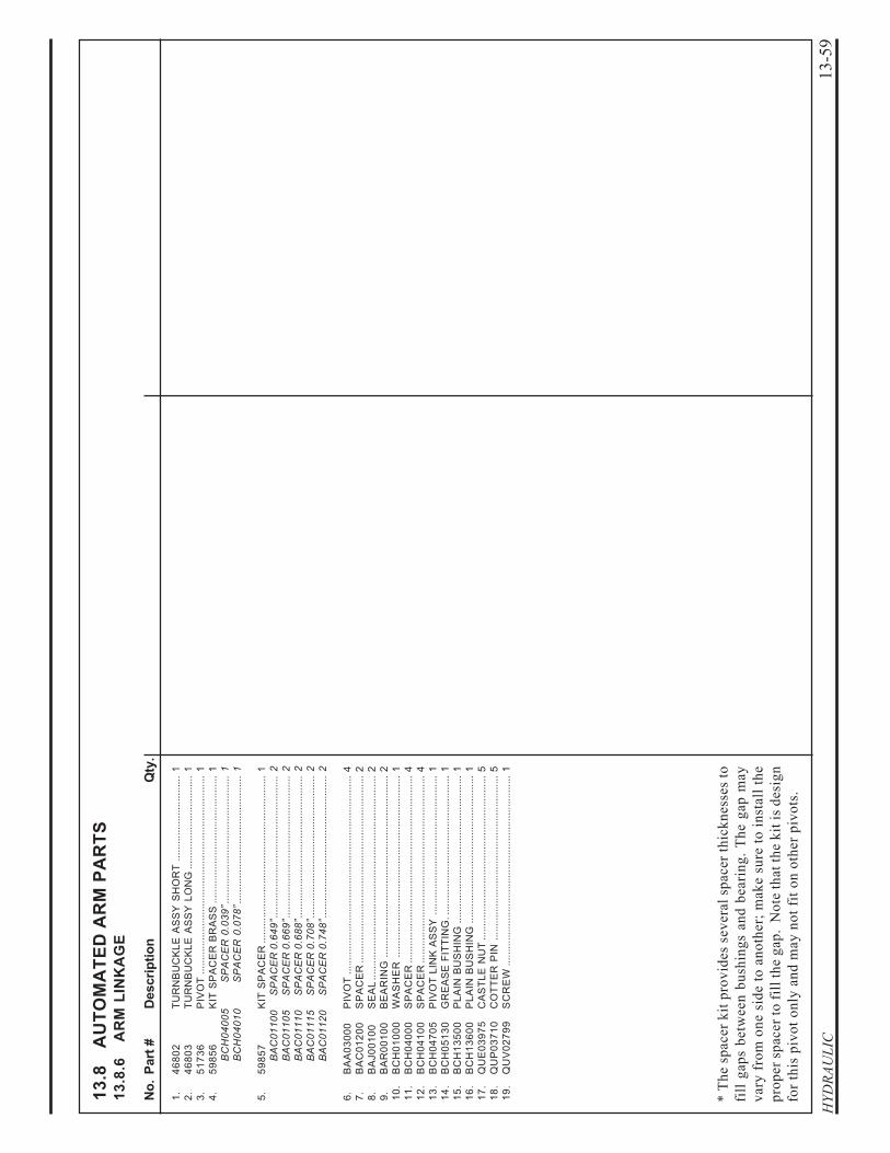
13-5
9H
YDRA
ULI
C
13.8
AU
TOM
ATE
D A
RM
PA
RTS
13.8
.6A
RM
LIN
KA
GE
No.
Part
#D
escr
iptio
n Q
ty.
1.46
802
TUR
NB
UC
KLE
AS
SY
SH
OR
T...
......
......
......
......
...1
2.46
803
TUR
NB
UC
KLE
AS
SY
LO
NG
......
......
......
......
......
...1
3.51
736
PIV
OT
......
......
......
......
......
......
......
......
......
......
......
....1
4.59
856
KIT
SP
AC
ER
BR
AS
S...
......
......
......
......
......
......
......
1B
CH
0400
5S
PA
CE
R 0
.039
”....
......
......
......
......
......
......
.....
1B
CH
0401
0S
PA
CE
R 0
.078
”....
......
......
......
......
......
......
.....
1
5.59
857
KIT
SP
AC
ER
......
......
......
......
......
......
......
......
......
.....
1B
AC
0110
0S
PA
CE
R 0
.649
”....
......
......
......
......
......
......
......
....
2B
AC
0110
5S
PA
CE
R 0
.669
”....
......
......
......
......
......
......
......
....
2B
AC
0111
0S
PA
CE
R 0
.688
”....
......
......
......
......
......
......
......
....
2B
AC
0111
5S
PA
CE
R 0
.708
”....
......
......
......
......
......
......
......
....
2B
AC
0112
0S
PA
CE
R 0
.748
”....
......
......
......
......
......
......
......
....
2
6.B
AA
0300
0P
IVO
T...
......
......
......
......
......
......
......
......
......
......
......
.47.
BA
C01
200
SP
AC
ER
......
......
......
......
......
......
......
......
......
......
......
28.
BA
J001
00S
EA
L...
......
......
......
......
......
......
......
......
......
......
......
...2
9.B
AR
0010
0B
EA
RIN
G...
......
......
......
......
......
......
......
......
......
......
.210
.B
CH
0100
0W
AS
HE
R...
......
......
......
......
......
......
......
......
......
......
.111
.B
CH
0400
0S
PA
CE
R...
......
......
......
......
......
......
......
......
......
......
...4
12.
BC
H04
100
SP
AC
ER
......
......
......
......
......
......
......
......
......
......
......
413
.B
CH
0470
5P
IVO
T LI
NK
AS
SY
......
......
......
......
......
......
......
......
.114
.B
CH
0513
0G
RE
AS
E F
ITTI
NG
.....
......
......
......
......
......
......
......
...1
15.
BC
H13
500
PLA
IN B
US
HIN
G...
......
......
......
......
......
......
......
......
.116
.B
CH
1360
0P
LAIN
BU
SH
ING
......
......
......
......
......
......
......
......
....1
17.
QU
E03
975
CA
STL
E N
UT
......
......
......
......
......
......
......
......
......
....5
18.
QU
P03
710
CO
TTE
R P
IN...
......
......
......
......
......
......
......
......
......
.519
.Q
UV
0279
9S
CR
EW
......
......
......
......
......
......
......
......
......
......
......
.1
* Th
e sp
acer
kit
prov
ides
sev
eral
spa
cer t
hick
ness
es to
fill
gaps
bet
wee
n bu
shin
gs a
nd b
eari
ng. T
he g
ap m
ayva
ry fr
om o
ne s
ide
to a
noth
er; m
ake
sure
to in
stal
l the
prop
er sp
acer
to fi
ll th
e ga
p. N
ote
that
the
kit i
s des
ign
for t
his
pivo
t onl
y an
d m
ay n
ot fi
t on
othe
r piv
ots.

EXPE
RT 2
000
13-6
0
13.8
AU
TOM
ATE
D A
RM
PA
RTS
13.8
.7G
RA
BB
ER

13-6
1H
YDRA
ULI
C
13.8
AU
TOM
ATE
D A
RM
PA
RTS
13.8
.7G
RA
BB
ER
No.
Part
#D
escr
iptio
n Q
ty.
BC
H02
205
GR
AB
BE
R A
SS
Y...
......
......
......
......
......
......
......
......
.1
1.33
637
RO
D A
SS
Y..
......
......
......
......
......
......
......
......
......
......
12.
4681
6S
PR
ING
BLA
DE
LIN
ING
......
......
......
......
......
......
....2
3.46
817
SP
RIN
G B
LAD
E L
ININ
G...
......
......
......
......
......
......
.14.
5151
0P
IVO
T...
......
......
......
......
......
......
......
......
......
......
......
.25.
BA
A00
500
PIV
OT
......
......
......
......
......
......
......
......
......
......
......
....1
6.B
AA
0051
0P
IVO
T...
......
......
......
......
......
......
......
......
......
......
......
.27.
BA
A00
520
PIV
OT
......
......
......
......
......
......
......
......
......
......
......
....1
8.B
AA
0401
0G
RA
B S
UP
PO
RT
AS
SY
.....
......
......
......
......
......
.....
19.
BA
C00
250
STR
AP
......
......
......
......
......
......
......
......
......
......
......
...2
10.
BA
C00
255
STR
AP
PR
OTE
CTO
R...
......
......
......
......
......
......
.....
211
.B
AC
0026
0S
TRA
P S
UP
PO
RT
......
......
......
......
......
......
......
......
.212
.B
AC
0040
0S
TRA
P...
......
......
......
......
......
......
......
......
......
......
......
113
.B
AC
0040
5S
TRA
P P
RO
TEC
TOR
......
......
......
......
......
......
......
..1
14.
BA
C00
410
STR
AP
SU
PP
OR
T...
......
......
......
......
......
......
......
....1
15.
BA
L002
50S
PR
ING
BLA
DE
......
......
......
......
......
......
......
......
.....
216
.B
AL0
0400
SP
RIN
G B
LAD
E...
......
......
......
......
......
......
......
......
..1
17.
BC
H02
300
NU
T15
18.
BC
H02
400
BO
LT...
......
......
......
......
......
......
......
......
......
......
......
..6
19.
BC
H02
500
CLA
MP
ING
PLA
TE...
......
......
......
......
......
......
......
...3
20.
BC
H03
000
SP
AC
ER
......
......
......
......
......
......
......
......
......
......
......
221
.B
CH
0320
0B
OLT
......
......
......
......
......
......
......
......
......
......
......
.....
422
.B
CH
0340
0FL
AT
HE
AD
BO
LT...
......
......
......
......
......
......
......
....2
23.
BC
H04
200
WA
SH
ER
FLA
T...
......
......
......
......
......
......
......
......
.21
24.
BC
H05
125
GR
EA
SE
FIT
TIN
G...
......
......
......
......
......
......
......
.....
225
.B
CH
1280
0S
PR
ING
SU
PP
OR
T S
ING
LE A
SS
Y.
......
......
......
..1
26.
BC
H12
900
BU
SH
ING
......
......
......
......
......
......
......
......
......
......
....4
27.
BC
H13
000
SP
RIN
G S
UP
PO
RT
DO
UB
LE A
SS
Y..
......
......
......
128
.B
CH
1340
0B
ON
D P
LATE
......
......
......
......
......
......
......
......
......
...1
29.
HY
C00
170
GR
AB
BE
R C
YLI
ND
ER
AS
SY
.....
......
......
......
......
...1
30.
QU
B00
890
EY
E B
OLT
......
......
......
......
......
......
......
......
......
......
...4
31.
QU
B02
750
BO
LT...
......
......
......
......
......
......
......
......
......
......
......
..4
32.
QU
B02
915
BO
LT...
......
......
......
......
......
......
......
......
......
......
......
..2
33.
QU
B03
902
FLA
T H
EA
D B
OLT
......
......
......
......
......
......
......
......
.934
.Q
UB
0477
5B
OLT
......
......
......
......
......
......
......
......
......
......
......
.....
535
.Q
UB
0581
1FL
AT
HE
AD
BO
LT...
......
......
......
......
......
......
......
....6
36.
QU
B06
251
BO
LT...
......
......
......
......
......
......
......
......
......
......
......
..8
37.
QU
E01
200
NU
T...
......
......
......
......
......
......
......
......
......
......
......
...2
38.
QU
E01
500
LOC
K N
UT
......
......
......
......
......
......
......
......
......
......
2139
.Q
UE
0180
0N
UT
......
......
......
......
......
......
......
......
......
......
......
......
4

EXPE
RT 2
000
13-6
2
13.8
AU
TOM
ATE
D A
RM
PA
RTS
13.8
.8IN
NER
BO
OM
BU
MPE
R

13-6
3H
YDRA
ULI
C
13.8
AU
TOM
ATE
D A
RM
PA
RTS
13.8
.8IN
NER
BO
OM
BU
MPE
R
No.
Part
#D
escr
iptio
n Q
ty.
1.59
850
IDE
NTI
FIC
ATI
ON
STI
CK
ER
......
......
......
......
......
....3
2.B
CH
0030
0W
AS
HE
R...
......
......
......
......
......
......
......
......
......
......
.13.
BC
H01
200
LOC
K W
AS
HE
R...
......
......
......
......
......
......
......
......
..1
4.B
CH
1420
0ID
EN
TIFI
CA
TIO
N S
TIC
KE
R...
......
......
......
......
......
.15.
QU
B00
120
BU
MP
ER
......
......
......
......
......
......
......
......
......
......
.....
16.
QU
B04
840
BO
LT...
......
......
......
......
......
......
......
......
......
......
......
..1

EXPE
RT 2
000
13-6
4
13.8
AU
TOM
ATE
D A
RM
PA
RTS
13.8
.9O
UTE
R B
OO
M L
INK
AG
E

13-6
5H
YDRA
ULI
C
13.8
AU
TOM
ATE
D A
RM
PA
RTS
13.8
.9O
UTE
R B
OO
M L
INK
AG
E
No.
Part
#D
escr
iptio
n Q
ty.
4680
3TU
RN
BU
CK
LE A
SS
Y.
LON
G...
......
......
......
......
.....
1
1.46
804
TUR
NB
UC
KLE
......
......
......
......
......
......
......
......
......
..1
2.46
806
RO
D E
ND
(rig
ht-h
and
thre
ad).
......
......
......
......
......
13.
4680
7R
OD
EN
D (
left-
hand
thre
ad).
......
......
......
......
......
..1
4.B
AR
0050
0S
PH
ER
ICA
L P
LAIN
BE
AR
ING
......
......
......
......
......
25.
BC
H04
600
SN
AP
RIN
G...
......
......
......
......
......
......
......
......
......
...4
6.B
CH
0512
5G
RE
AS
E F
ITTI
NG
......
......
......
......
......
......
......
......
..2
7.Q
UE
0195
0JA
M N
UT
(rig
ht-h
and
thre
ad).
......
......
......
......
......
.18.
QU
E01
951
JAM
NU
T (le
ft-ha
nd th
read
)....
......
......
......
......
......
1

EXPE
RT 2
000
13-6
6
13.8
AU
TOM
ATE
D A
RM
PA
RTS
13.8
.10
INN
ER B
OO
M L
INK
AG
E

13-6
7H
YDRA
ULI
C
13.8
AU
TOM
ATE
D A
RM
PA
RTS
13.8
.10
INN
ER B
OO
M L
INK
AG
E
No.
Part
#D
escr
iptio
n Q
ty.
4680
2TU
RN
BU
CK
LE A
SS
Y.
SH
OR
T...
......
......
......
......
..1
1.46
805
TUR
NB
UC
KLE
......
......
......
......
......
......
......
......
......
..1
2.46
806
RO
D E
ND
(rig
ht-h
and
thre
ad).
......
......
......
......
......
13.
4680
7R
OD
EN
D (
left-
hand
thre
ad).
......
......
......
......
......
..1
4.B
AR
0050
0S
PH
ER
ICA
L P
LAIN
BE
AR
ING
......
......
......
......
......
25.
BC
H04
600
SN
AP
RIN
G...
......
......
......
......
......
......
......
......
......
...4
6.B
CH
0512
5G
RE
AS
E F
ITTI
NG
......
......
......
......
......
......
......
......
..2
7.Q
UE
0195
0JA
M N
UT
(rig
ht-h
and
thre
ad).
......
......
......
......
......
.18.
QU
E01
951
JAM
NU
T (le
ft-ha
nd th
read
)....
......
......
......
......
......
1

EXPE
RT 2
000
13-6
8
13.8
AU
TOM
ATE
D A
RM
PA
RTS
13.8
.11
PRO
XIM
ITY
SWIT
CH
BR
AC
KET

13-6
9H
YDRA
ULI
C
13.8
AU
TOM
ATE
D A
RM
PA
RTS
13.8
.11
INN
ER B
OO
M L
INK
AG
E
No.
Part
#D
escr
iptio
n Q
ty.
1.38
569
BR
AC
KE
T, P
RO
XIM
ITY
SW
ITC
H...
......
......
......
....1
2.51
667
BR
AC
KE
T, P
RO
XIM
ITY
SW
ITC
H...
......
......
......
....1
3.Q
UB
0190
1B
OLT
......
......
......
......
......
......
......
......
......
......
......
.....
24.
QU
E01
200
NU
T...
......
......
......
......
......
......
......
......
......
......
......
...2
5.Q
UB
0280
1B
OLT
......
......
......
......
......
......
......
......
......
......
......
.....
2

EXPE
RT 2
000
13-7
0
13.8
AU
TOM
ATE
D A
RM
PA
RTS
13.8
.12
AR
M H
YDR
AU
LIC

13-7
1H
YDRA
ULI
C
13.8
AU
TOM
ATE
D A
RM
PA
RTS
13.8
.12
AR
M H
YDR
AU
LIC
No.
Part
#D
escr
iptio
n Q
ty.
1.B
CH
0050
0S
LEE
VE
NY
LON
......
......
......
......
......
......
......
......
12.
BC
H00
650
SLE
EV
E N
YLO
N...
......
......
......
......
......
......
......
...1
3.B
CH
0260
0W
AS
HE
R L
OC
K...
......
......
......
......
......
......
......
....2
4.B
CH
0270
0W
AS
HE
R...
......
......
......
......
......
......
......
......
......
...2
5.B
CH
0280
0B
OLT
......
......
......
......
......
......
......
......
......
......
......
.26.
BC
H11
000
VA
LVE
, FL
OW
CO
NTR
OL
......
......
......
......
......
..1
7.H
YS
0060
2S
UP
PO
RT,
HY
DR
AU
LIC
......
......
......
......
......
......
...6
8.B
CH
1120
0TU
BIN
G...
......
......
......
......
......
......
......
......
......
......
....2
9.B
CH
1150
0TU
BIN
G...
......
......
......
......
......
......
......
......
......
......
....1
10.
BC
H11
600
TUB
ING
......
......
......
......
......
......
......
......
......
......
......
.111
.B
CH
1170
0H
OS
E...
......
......
......
......
......
......
......
......
......
......
......
..1
12.
BC
H11
800
HO
SE
......
......
......
......
......
......
......
......
......
......
......
.....
113
.B
CH
1190
0H
OS
E...
......
......
......
......
......
......
......
......
......
......
......
..1
14.
BC
H12
000
HO
SE
......
......
......
......
......
......
......
......
......
......
......
.....
115
.B
CH
1210
0H
OS
E...
......
......
......
......
......
......
......
......
......
......
......
..1
16.
BC
H12
200
HO
SE
......
......
......
......
......
......
......
......
......
......
......
.....
117
.B
CH
1230
0H
OS
E...
......
......
......
......
......
......
......
......
......
......
......
..1
18.
BC
H12
400
HO
SE
......
......
......
......
......
......
......
......
......
......
......
.....
119
.B
CH
1370
0TU
BIN
G...
......
......
......
......
......
......
......
......
......
......
....1
20.
BC
H13
800
TUB
ING
......
......
......
......
......
......
......
......
......
......
......
.121
.B
CH
1410
0S
TRA
IGH
T FI
TTIN
G...
......
......
......
......
......
......
......
..1
22.
BC
H14
105
STR
AIG
HT
FITT
ING
......
......
......
......
......
......
......
.....
123
.H
YC
0017
0G
RA
BB
ER
CY
LIN
DE
R A
SS
Y..
......
......
......
......
.1
24.
HY
C00
204
OU
TER
BO
OM
CY
LIN
DE
R...
......
......
......
......
....1
25.
HY
C00
216
LOW
ER
BO
OM
CY
LIN
DE
R...
......
......
......
......
....1
26.
HY
F027
75FI
TTIN
G E
LBO
W...
......
......
......
......
......
......
......
..1
27.
HY
F027
85FI
TTIN
G E
LBO
W...
......
......
......
......
......
......
......
..2
28.
HY
F056
62FI
TTIN
G T
EE
......
......
......
......
......
......
......
......
......
....1
29.
HY
F074
00FI
TTIN
G E
LBO
W...
......
......
......
......
......
......
......
......
.130
.H
YV
0750
8V
ALV
E A
SS
Y..
......
......
......
......
......
......
......
......
......
..1

EXPE
RT 2
000
13-7
2
13.8
AU
TOM
ATE
D A
RM
PA
RTS
13.8
.13
OU
TER
BO
OM
CYL
IND
ER

13-7
3H
YDRA
ULI
C
13.8
AU
TOM
ATE
D A
RM
PA
RTS
13.8
.13
OU
TER
BO
OM
CYL
IND
ER
No.
Part
#D
escr
iptio
n Q
ty.
HY
C00
204
OU
TER
BO
OM
CY
LIN
DE
R...
......
......
......
......
......
..1
1.H
YJ0
3097
CY
LIN
DE
R S
EA
L K
IT...
......
......
......
......
......
......
......
12.
HY
F051
25E
LBO
W U
NIO
N...
......
......
......
......
......
......
......
......
...2

EXPE
RT 2
000
13-7
4
13.8
AU
TOM
ATE
D A
RM
PA
RTS
13.8
.14
INN
ER B
OO
M C
YLIN
DER

13-7
5H
YDRA
ULI
C
13.8
AU
TOM
ATE
D A
RM
PA
RTS
13.8
.14
INN
ER B
OO
M C
YLIN
DER
No.
Part
#D
escr
iptio
n Q
ty.
HY
C00
216
INN
ER
BO
OM
CY
LIN
DE
R A
SS
Y.
......
......
......
......
1
1.49
802
HY
DR
AU
LIC
PIP
E...
......
......
......
......
......
......
......
.....
12.
BA
M00
100
BLO
CK
VA
LVE
AS
S'Y
......
......
......
......
......
......
......
.13.
HY
J031
05C
YLI
ND
ER
SE
AL
KIT
......
......
......
......
......
......
......
...1
4.H
YF0
5140
TEE
UN
ION
......
......
......
......
......
......
......
......
......
......
.15.
HY
F082
70A
DA
PTO
R U
NIO
N...
......
......
......
......
......
......
......
.....
1
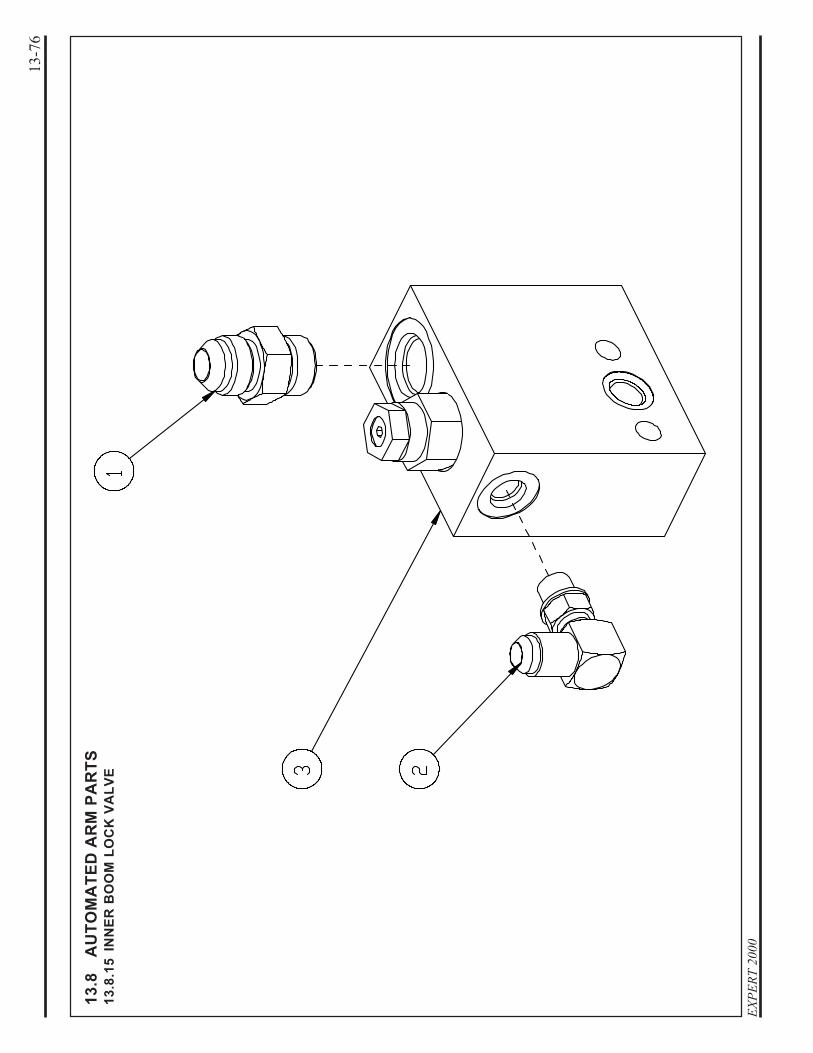
EXPE
RT 2
000
13-7
6
13.8
AU
TOM
ATE
D A
RM
PA
RTS
13.8
.15
INN
ER B
OO
M L
OC
K V
ALV
E

13-7
7H
YDRA
ULI
C
13.8
AU
TOM
ATE
D A
RM
PA
RTS
13.8
.15
INN
ER B
OO
M L
OC
K V
ALV
E
No.
Part
#D
escr
iptio
n Q
ty.
BA
M00
100
VA
LVE
BLO
CK
AS
SY
.....
......
......
......
......
......
......
...1
1.H
YF0
5110
AD
AP
TOR
......
......
......
......
......
......
......
......
......
......
...1
2.H
YF0
7300
ELB
OW
UN
ION
......
......
......
......
......
......
......
......
......
13.
HY
V07
507
VA
LVE
BLO
CK
AS
SY
.....
......
......
......
......
......
......
...1

EXPE
RT 2
000
13-7
8
13.8
AU
TOM
ATE
D A
RM
PA
RTS
13.8
.16
INN
ER B
OO
M L
OC
K V
ALV
E B
LOC
K

13-7
9H
YDRA
ULI
C
13.8
AU
TOM
ATE
D A
RM
PA
RTS
13.8
.16
INN
ER B
OO
M L
OC
K V
ALV
E B
LOC
K
No.
Part
#D
escr
iptio
n Q
ty.
HY
V07
507
VA
LVE
BLO
CK
AS
SY
.....
......
......
......
......
......
......
...1
1.B
AC
0200
0C
AR
TRID
GE
......
......
......
......
......
......
......
......
......
.....
12.
BA
M00
150
MA
NIF
OLD
......
......
......
......
......
......
......
......
......
......
..1
3.H
YF1
1350
PLU
G...
......
......
......
......
......
......
......
......
......
......
......
..1
4.H
YJ0
1340
O-R
ING
......
......
......
......
......
......
......
......
......
......
......
.1

EXPE
RT 2
000
13-8
0
13.8
AU
TOM
ATE
D A
RM
PA
RTS
13.8
.17
GR
AB
BER
CYL
IND
ER

13-8
1H
YDRA
ULI
C
13.8
AU
TOM
ATE
D A
RM
PA
RTS
13.8
.17
GR
AB
BER
CYL
IND
ER
No.
Part
#D
escr
iptio
n Q
ty.
HY
C00
170
GR
AB
BE
R C
YLI
ND
ER
......
......
......
......
......
......
......
1
1.H
YJ0
3003
CY
LIN
DE
R S
EA
L S
EA
L...
......
......
......
......
......
......
..1
2.H
YF0
7400
ELB
OW
UN
ION
......
......
......
......
......
......
......
......
......
1

EXPE
RT 2
000
13-8
2
13.8
AU
TOM
ATE
D A
RM
PA
RTS
13.8
.18
GR
AB
BER
LO
CK
VA
LVE

13-8
3H
YDRA
ULI
C
13.8
AU
TOM
ATE
D A
RM
PA
RTS
13.8
.18
GR
AB
BER
LO
CK
VA
LVE
No.
Part
#D
escr
iptio
n Q
ty.
BC
H02
900
GR
AB
BE
R L
OC
K V
ALV
E A
SS
Y..
......
......
......
......
.1
1.B
CH
0260
0W
AS
HE
R L
OC
K...
......
......
......
......
......
......
......
......
..2
2.B
CH
0270
0W
AS
HE
R...
......
......
......
......
......
......
......
......
......
......
.23.
BC
H02
800
BO
LT...
......
......
......
......
......
......
......
......
......
......
......
..2
4.H
YF0
2775
FITT
ING
ELB
OW
......
......
......
......
......
......
......
......
....1
5.H
YF0
2785
FITT
ING
ELB
OW
......
......
......
......
......
......
......
......
....2
6.H
YF0
5662
FITT
ING
TE
E...
......
......
......
......
......
......
......
......
......
.17.
HY
F074
00FI
TTIN
G E
LBO
W...
......
......
......
......
......
......
......
......
.18.
HY
V07
508
VA
LVE
AS
SY
.....
......
......
......
......
......
......
......
......
.....
1

EXPE
RT 2
000
13-8
4
13.8
AU
TOM
ATE
D A
RM
PA
RTS
13.8
.19
GR
AB
BER
LO
CK
VA
LVE
CA
RTR
IDG
E

13-8
5H
YDRA
ULI
C
13.8
AU
TOM
ATE
D A
RM
PA
RTS
13.8
.19
GR
AB
BER
LO
CK
VA
LVE
CA
RTR
IDG
E
No.
Part
#D
escr
iptio
n Q
ty.
HY
V07
508
VA
LVE
AS
SY
.....
......
......
......
......
......
......
......
......
.....
1
1.B
AC
0210
0C
AR
TRID
GE
......
......
......
......
......
......
......
......
......
.....
12.
HY
M01
250
MA
NIF
OLD
......
......
......
......
......
......
......
......
......
......
..1

EXPERT 2000
13-86
NOTES

13-87
COOL HAND AUTOMATED ARM
NOTES