cooling tower selection guide - · pdf fileupdate cooling tower selection guide produced by...
TRANSCRIPT
UPDATE
Cooling Tower Selection Guide
http://qtcapps.ct.spx.com/update/Login.aspx
Produced by
Salt Lake City: Ph. 801-486-0767 | Fax 801-485-6364
Las Vegas: Ph. 702-948-8407 | Fax 702-948-8408
www.gritton.com
Contents Section I: Basic Features ............................................................................................................................... 3
Selection Page ........................................................................................................................................... 3
Miscellaneous ....................................................................................................................................... 3
“Products”: ............................................................................................................................................ 3
Selection Page ........................................................................................................................................... 5
“Design Conditions” Tab: ...................................................................................................................... 5
Output Page .............................................................................................................................................. 7
Section II: Advanced Features ....................................................................................................................... 9
Selection Page ........................................................................................................................................... 9
“Evaluation Parameters” Tab: Used for energy cost analysis and life-cycle costing ............................ 9
Selection Page ......................................................................................................................................... 11
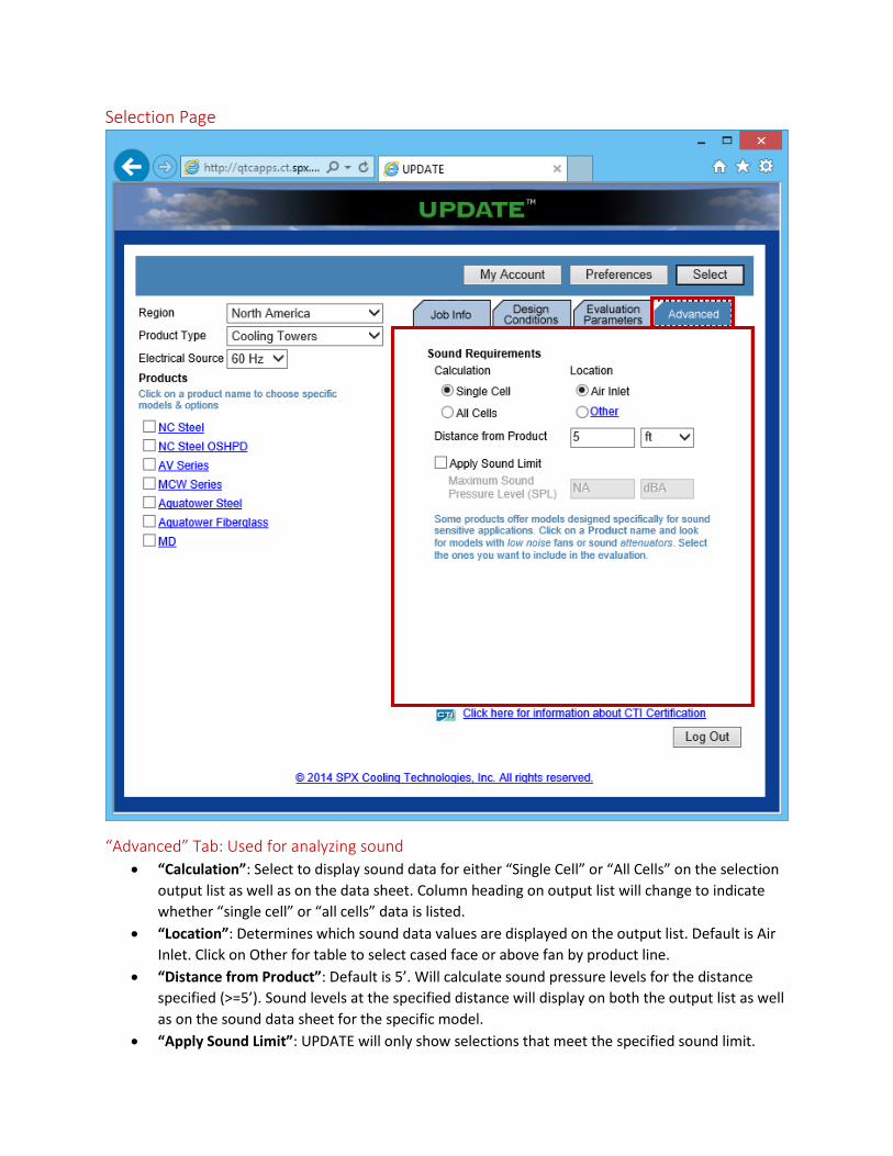
“Advanced” Tab: Used for analyzing sound ........................................................................................ 11
Section I: Basic Features
Selection Page
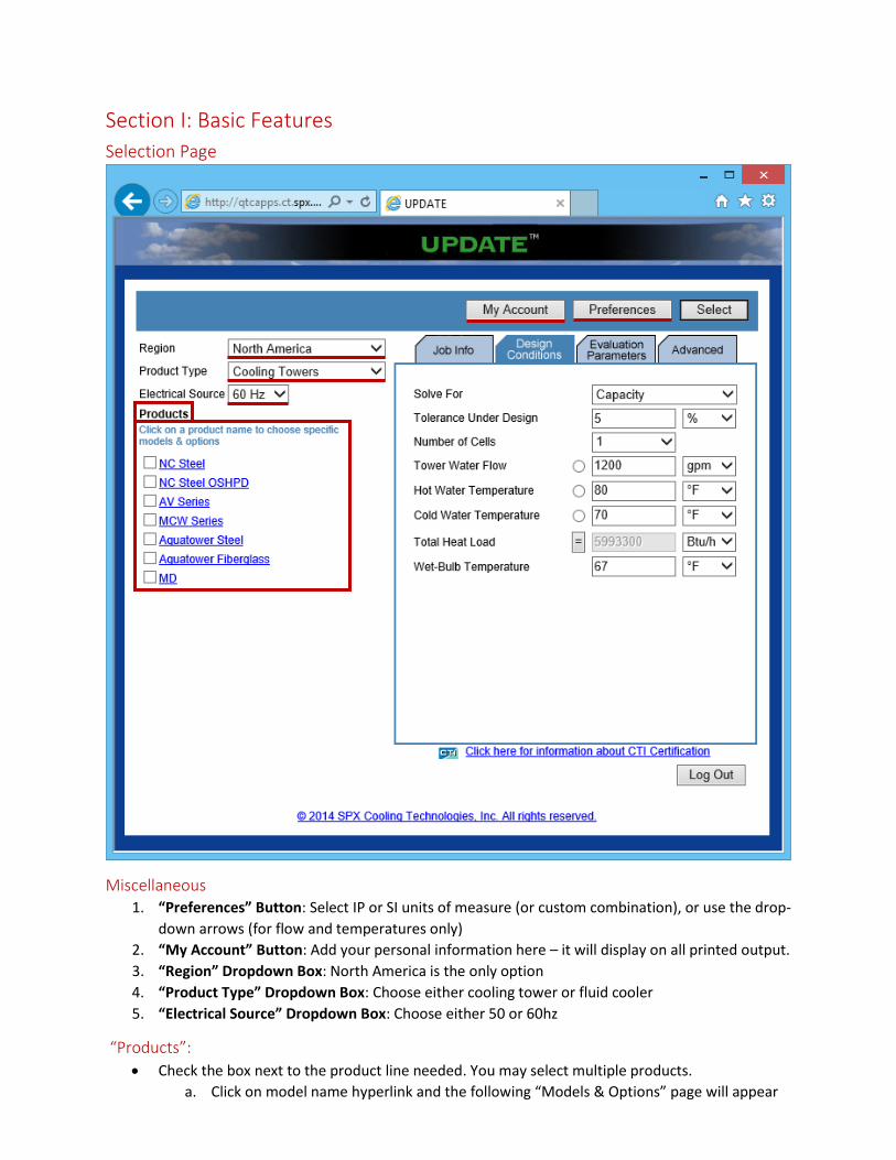
Miscellaneous 1. “Preferences” Button: Select IP or SI units of measure (or custom combination), or use the drop-
down arrows (for flow and temperatures only)
2. “My Account” Button: Add your personal information here – it will display on all printed output.
3. “Region” Dropdown Box: North America is the only option
4. “Product Type” Dropdown Box: Choose either cooling tower or fluid cooler
5. “Electrical Source” Dropdown Box: Choose either 50 or 60hz
“Products”:
Check the box next to the product line needed. You may select multiple products.
a. Click on model name hyperlink and the following “Models & Options” page will appear
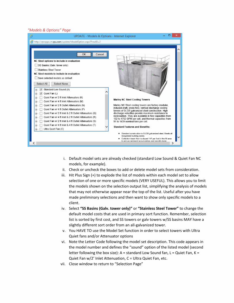
“Models & Options” Page
i. Default model sets are already checked (standard Low Sound & Quiet Fan NC
models, for example).
ii. Check or uncheck the boxes to add or delete model sets from consideration.
iii. Hit Plus Sign (+) to explode the list of models within each model set to allow
selection of one or more specific models (VERY USEFUL). This allows you to limit
the models shown on the selection output list, simplifying the analysis of models
that may not otherwise appear near the top of the list. Useful after you have
made preliminary selections and then want to show only specific models to a
client.
iv. Select “SS Basins (Galv. tower only)” or “Stainless Steel Tower” to change the
default model costs that are used in primary sort function. Remember, selection
list is sorted by first cost, and SS towers or galv towers w/SS basins MAY have a
slightly different sort order from an all-galvanized tower.
v. You HAVE TO use the Model Set function in order to select towers with Ultra
Quiet fans and/or Attenuator options
vi. Note the Letter Code following the model set description. This code appears in
the model number and defines the “sound” option of the listed model (second
letter following the box size): A = standard Low Sound fan, L = Quiet Fan, K =
Quiet Fan w/2’ Inlet Attenuation, C = Ultra Quiet Fan, etc.
vii. Close window to return to “Selection Page”
Selection Page
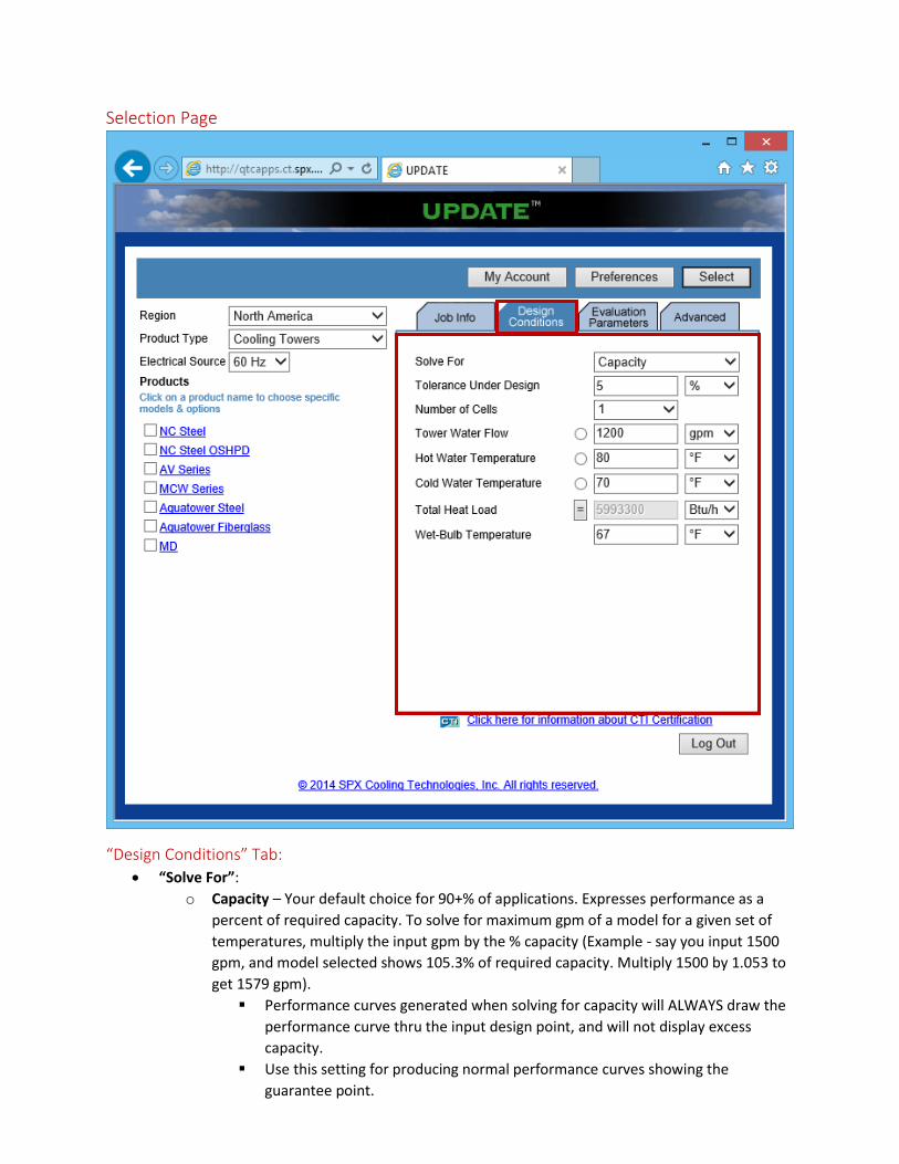
“Design Conditions” Tab:
“Solve For”:
o Capacity – Your default choice for 90+% of applications. Expresses performance as a
percent of required capacity. To solve for maximum gpm of a model for a given set of
temperatures, multiply the input gpm by the % capacity (Example - say you input 1500
gpm, and model selected shows 105.3% of required capacity. Multiply 1500 by 1.053 to
get 1579 gpm).
Performance curves generated when solving for capacity will ALWAYS draw the
performance curve thru the input design point, and will not display excess
capacity.
Use this setting for producing normal performance curves showing the
guarantee point.

o Cold Water – expresses cold water temp tower is actually capable of producing at full
speed, so a tower with excess capacity will show colder water at the design point. It will
actually CHANGE the design CW temp on the data sheet for each model to reflect its CW
capability. The RANGE remains the same.
Use this setting with the ‘Curves’ function to show the tower capacity at less
than full fan speed. Slow the fan down (curve parameters) to move the CW
temp back up to the original design point.
Curve will display the reduced fan speed and the resulting reduced BHP
This function can also be used for selection of a tower/Plate Heat Exchanger
(PHE) combination in order to fully-load the tower and show the CW temps
different tower models can produce. Use these temps for the cold side of the
PHE selection.
o Wet Bulb – Displays the WB at which the tower can produce a given CW temp (>
capacity = > WB)
“Tolerance Under Design”: allows you to see models that are just slightly undersized to allow
evaluation of models that may be otherwise attractive alternative selections (default is 5%, user
adjustable from 0 – 10% undersize)
“Number of Cells”: to evaluate, or allow the program to ‘calculate’ on basis of cost.
Design Conditions: Input flow, temperatures and/or heat load as available)
o Fahrenheit/Celsius conversion - drop-downs on temps provide very useful means of
converting units
o Move = sign to ‘unknown’ value
o Total Heat Load’ takes SH, SG & Conductivity into account for water temps.
“Select” Button: Runs the program to produce a sorted list of towers that meet the selection
criteria (the Output Screen).
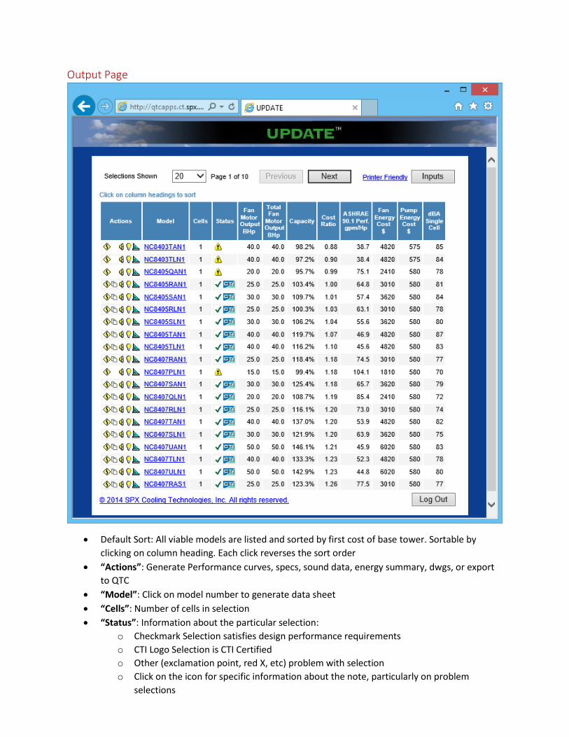
Output Page
Default Sort: All viable models are listed and sorted by first cost of base tower. Sortable by
clicking on column heading. Each click reverses the sort order
“Actions”: Generate Performance curves, specs, sound data, energy summary, dwgs, or export
to QTC
“Model”: Click on model number to generate data sheet
“Cells”: Number of cells in selection
“Status”: Information about the particular selection:
o Checkmark Selection satisfies design performance requirements
o CTI Logo Selection is CTI Certified
o Other (exclamation point, red X, etc) problem with selection
o Click on the icon for specific information about the note, particularly on problem
selections

“Fan Motor Output BHp”: Clumn shows total hp per cell
“Total Fan Motor Output BHp”: Column shows total hp per tower
“Capacity”: Indicates % of required capacity available from this model. Curves will always be
drawn thru DESIGN POINT.
o “Minimum Cold Water °F”: (if changed in “Solve for”) Indicates CW temp capability at
defined flow, range and WB. Curves will show actual CW capability at design WB
o “Maximum Wet-Bulb °F”: (in “Solve for” mode) indicates the WB at which tower is
capable of doing design Flow, HW & CW. Curves will show actual WB capability for
design flow, HW & CW
“Cost Ratio”:
“ASHRAE 90.1 gpm/Hp”: Lists tower’s efficiency at conditions of 3 gpm/ton, 95 – 85 – 75 WB
(Has no bearing on tower’s efficiency at the ‘design’ duty
“Fan Energy Cost $”: Calculates PRESENT VALUE of fan or pump energy over the time period and
load profile defined in “Evaluation Parameters” tab.
“Pump Energy Cost $”: Calculates PRESENT VALUE of pump energy over the time period and
load profile defined in “Evaluation Parameters” tab.
“dBA”: Sound pressure level for this model at the conditions you have defined on the
“Advanced” tab. Default is single cell dBA @ 5’ from inlet face. You can change to multi-cell, at
any distance >5’, at either face or above fan.
Section II: Advanced Features
Selection Page
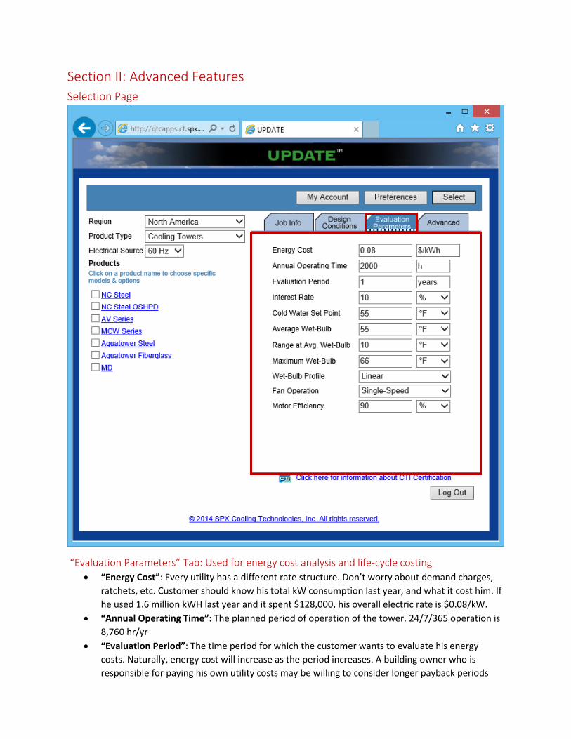
“Evaluation Parameters” Tab: Used for energy cost analysis and life-cycle costing
“Energy Cost”: Every utility has a different rate structure. Don’t worry about demand charges,
ratchets, etc. Customer should know his total kW consumption last year, and what it cost him. If
he used 1.6 million kWH last year and it spent $128,000, his overall electric rate is $0.08/kW.
“Annual Operating Time”: The planned period of operation of the tower. 24/7/365 operation is
8,760 hr/yr
“Evaluation Period”: The time period for which the customer wants to evaluate his energy
costs. Naturally, energy cost will increase as the period increases. A building owner who is
responsible for paying his own utility costs may be willing to consider longer payback periods
than would a speculative office building developer whose tenants would be bearing the energy
costs (unless they are building a LEED building and marketing the building’s low energy cost).
“Interest Rate”: Present value annual discount rate.
“Cold Water Set Point”: Optimal minimum cold water temperature to be maintained by
operation al control of the tower (suggest 70 deg for HVAC).
“Average Wet Bulb”: The anticipated average WB temperature during the planned period of
operation (see table, page 20)
“Range at Average Wet Bulb”: The expected range over the tower at the average WB temp.
“Maximum Wet Bulb”: The anticipated maximum entering WB temp during a planned period of
operation (design WB)
“Wet Bulb Profile”: Characteristics of temp variation during a planned period of operation.
Choices are Linear, Summer and Seasonal. Linear assumes an equal number of hours at each
wet bulb temp defined by the inputs of average and maximum WB temps. Summer assumes a
temp profile typical of warm climatic operation (Florida, Gulf Coast as examples). Seasonal
assumes a typical temp profile characterized by wide temperature swings (most of US).
“Fan Operation”: Single-speed (cycled), 2-speed (full speed, half-speed or off) or Variable Speed
(infinite operating mode from zero to full speed).
“Motor Efficiency”: Goes into the energy kW calculation. Efficiencies of various hp 1800 & 1200
rpm EPACT (Marley Standard efficiency) or NEMA Premium (Marley High Efficiency) motors are
listed in the attached tables (see pages 21-22). 900 rpm motors are not within the scopes of
either EPACT or NEMA Premium definitions.
Selection Page
“Advanced” Tab: Used for analyzing sound
“Calculation”: Select to display sound data for either “Single Cell” or “All Cells” on the selection
output list as well as on the data sheet. Column heading on output list will change to indicate
whether “single cell” or “all cells” data is listed.
“Location”: Determines which sound data values are displayed on the output list. Default is Air
Inlet. Click on Other for table to select cased face or above fan by product line.
“Distance from Product”: Default is 5’. Will calculate sound pressure levels for the distance
specified (>=5’). Sound levels at the specified distance will display on both the output list as well
as on the sound data sheet for the specific model.
“Apply Sound Limit”: UPDATE will only show selections that meet the specified sound limit.