cooling towers - trane mid-america † rental services 5 cooling towers overview introduction this...
TRANSCRIPT
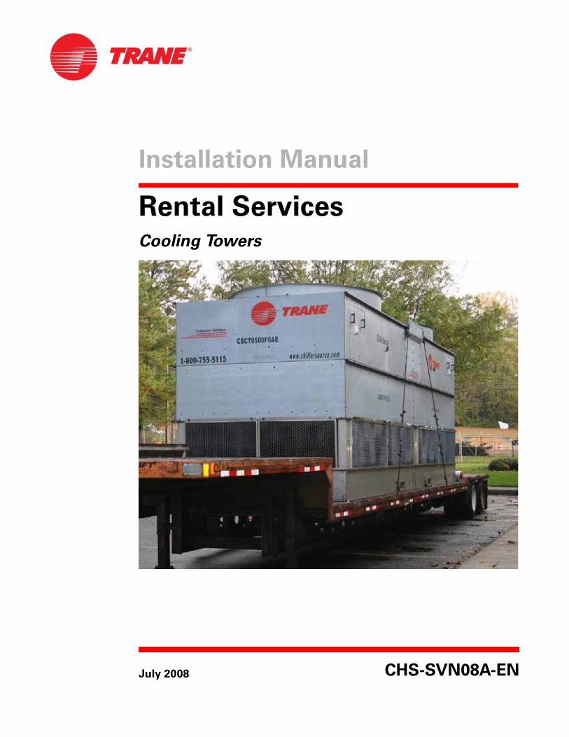
Installation Manual
Rental Services Cooling Towers
July 2008 CHS-SVN08A-EN
Copyright
© 2008 Trane All rights reserved
This document and the information in it are the property of Trane and may not be used or reproduced in whole or in part, without the written permission of Trane. Trane reserves the right to revise this publication at any time and to make changes to its content without obligation to notify any person of such revision or change.
Trademarks
Trane, the Trane logo, are trademarks of Trane in the United States and other countries. The following are trademarks or registered trademarks of their respective companies or organizations: Baltimore Aircoil from Baltimore Aircoil Company; Evapco from Evapco Inc.
Warnings and Cautions
Warnings and Cautions. Notice that warnings and cautions appear at appropriate intervals throughout this manual. Warnings are provided to alert installing parties of potential hazards that could result in personal injury or death, while cautions are designed to alert personnel to conditions that could result in equipment damage.
Your personal safety and the proper operation of the Trane Rental Services temporary chilled water system depend upon the strict observance of these precautions.
NOTICE: Warnings and Cautions appear at appropriate sections throughout this manual. Read these carefully.
� WARNING: Indicates a potentially hazardous situation which, if not avoided, could result in death or serious injury.
� CAUTION: Indicates a potentially hazardous situation which, if not avoided, may result in minor or moderate injury. It may also be used to alert against unsafe practices.
CAUTION: Indicates a situation that may result in equipment or property-damage only accidents.
CHS-PRB008-EN • Rental Services 3
Contents
Cooling Towers Overview . . . . . . . . . . . . . . . . . . . . . . . . . . . . . . . . . . . . . . . . . . . 5
Introduction . . . . . . . . . . . . . . . . . . . . . . . . . . . . . . . . . . . . . . . . . . . . . . . . . . . . 5
Units Affected . . . . . . . . . . . . . . . . . . . . . . . . . . . . . . . . . . . . . . . . . . . . . . . . . . 5
General Information . . . . . . . . . . . . . . . . . . . . . . . . . . . . . . . . . . . . . . . . . . . . . 6Weights and Dimensions . . . . . . . . . . . . . . . . . . . . . . . . . . . . . . . . . . . . . . . 7
Electrical Information . . . . . . . . . . . . . . . . . . . . . . . . . . . . . . . . . . . . . . . . . . . . . . 8
Piping Configurations . . . . . . . . . . . . . . . . . . . . . . . . . . . . . . . . . . . . . . . . . . . . . 10
PVC Spool Kit . . . . . . . . . . . . . . . . . . . . . . . . . . . . . . . . . . . . . . . . . . . . . . . . . . 13
Rigging Guidelines . . . . . . . . . . . . . . . . . . . . . . . . . . . . . . . . . . . . . . . . . . . . . . . 14
General Guidelines . . . . . . . . . . . . . . . . . . . . . . . . . . . . . . . . . . . . . . . . . . . . . 14
Line Drawings . . . . . . . . . . . . . . . . . . . . . . . . . . . . . . . . . . . . . . . . . . . . . . . . . . . . 16
250 ton Cooling Tower. . . . . . . . . . . . . . . . . . . . . . . . . . . . . . . . . . . . . . . . . . . 16
270 ton Cooling Tower. . . . . . . . . . . . . . . . . . . . . . . . . . . . . . . . . . . . . . . . . . . 17
500 ton Cooling Tower. . . . . . . . . . . . . . . . . . . . . . . . . . . . . . . . . . . . . . . . . . . 18
Startup Guidelines . . . . . . . . . . . . . . . . . . . . . . . . . . . . . . . . . . . . . . . . . . . . . . . . 19
Before Start-up . . . . . . . . . . . . . . . . . . . . . . . . . . . . . . . . . . . . . . . . . . . . . . . . 19
Start-up Guidelines . . . . . . . . . . . . . . . . . . . . . . . . . . . . . . . . . . . . . . . . . . . . . 19
Maintenance Guidelines . . . . . . . . . . . . . . . . . . . . . . . . . . . . . . . . . . . . . . . . . . . 20
Water Treatment Recommendations . . . . . . . . . . . . . . . . . . . . . . . . . . . . . . 20
Control of Biological Contamination . . . . . . . . . . . . . . . . . . . . . . . . . . . . . . . 21
Air Contamination . . . . . . . . . . . . . . . . . . . . . . . . . . . . . . . . . . . . . . . . . . . . . . 21

CHS-SVN08A-EN • Rental Services 5
Cooling Towers Overview
Introduction
This installation manual covers the rental cooling towers available for temporary cooling solutions. This includes cooling tower technical information, startup recommendations, and water treatment. The information contained in this manual is provided to ensure the safety of the equipment and its surroundings.
The information provided in this document is to be used as a quick reference to aid in determining certain limitations such as size, available power, or lifting requirements. Please always call for availability of equipment (including ancillary items: pumps, flexible hose, and transformers) prior to obtaining a purchase order from the customer. Equipment is available on a first-come, first-serve basis, but can be reserved with a signed rental agreement and order on the system.
Please review the Rental Services “Installation and Setup Guide” CD which gives you a description of Rental Services equipment and explains how to properly setup for rental applications. This can be ordered through Inland Printing (Order #: CHS-CMC002-EN).
Call Rental Services 24 x 7 at (800) 755-5115 for specific questions.
Units Affected
CSCT0250F0XX - 250-ton nominal cooling tower (750 GPM)
CSCT0270F0XX - 270-ton nominal cooling tower (810) GPM)
CSCT0500F0XX - 500- ton nominal cooling tower (1500 GPM)
Note: Where xx represents the unique inventory number
� WARNING
Live Electrical Components!
During installation, testing, servicing and troubleshooting of this product, it may be
necessary to work with live electrical components. Have a qualified licensed electrician
or other individual who has been properly trained in handling live electrical
components perform these tasks. Failure to follow all electrical safety precautions
when exposed to live electrical components could result in death or serious injury.
� WARNING Failure to follow state/local codes could result in death or serious injuries!
All cooling towers should be installed per the National Electric Code (NEC) and/or
applicable state/local codes.
Note: All information contained in this document is for reference only.
6 Rental Services • CHS-SVN08A-EN
Cooling Towers Overview
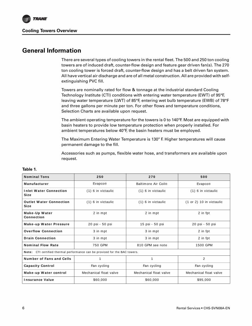
General Information
There are several types of cooling towers in the rental fleet. The 500 and 250 ton cooling towers are of induced draft, counter-flow design and feature gear driven fan(s). The 270 ton cooling tower is forced draft, counter-flow design and has a belt driven fan system. All have vertical air discharge and are of all metal construction. All are provided with self-extinguishing PVC fill.
Towers are nominally rated for flow & tonnage at the industrial standard Cooling Technology Institute (CTI) conditions with entering water temperature (EWT) of 95°F, leaving water temperature (LWT) of 85°F, entering wet bulb temperature (EWB) of 78°F and three gallons per minute per ton. For other flows and temperature conditions, Selection Charts are available upon request.
The ambient operating temperature for the towers is 0 to 140ºF. Most are equipped with basin heaters to provide low temperature protection when properly installed. For ambient temperatures below 40ºF, the basin heaters must be employed.
The Maximum Entering Water Temperature is 130º F. Higher temperatures will cause permanent damage to the fill.
Accessories such as pumps, flexible water hose, and transformers are available upon request.
Table 1.
Nominal Tons 250 270 500
Manufacturer Evapco® Baltimore Air Coil® Evapco®
Inlet Water Connection Size
(1) 6 in victaulic (1) 6 in victaulic (1) 6 in victaulic
Outlet Water Connection Size
(1) 6 in victaulic (1) 6 in victaulic (1 or 2) 10 in victaulic
Make-Up Water Connection
2 in mpt 2 in mpt 2 in fpt
Make-up Water Pressure 20 psi - 50 psi 15 psi - 50 psi 20 psi - 50 psi
Overflow Connection 3 in mpt 3 in mpt 2 in fpt
Drain Connection 3 in mpt 3 in mpt 2 in fpt
Nominal Flow Rate 750 GPM 810 GPM see note 1500 GPM
Note: CTI certified thermal performance can be proviced for the BAC towers.
Number of Fans and Cells 1 1 2
Capacity Control Fan cycling Fan cycling Fan cycling
Make-up Water control Mechanical float valve Mechanical float valve Mechanical float valve
Insurance Value $60,000 $60,000 $95,000
CHS-SVN08A-EN • Rental Services 7
Cooling Towers Overview
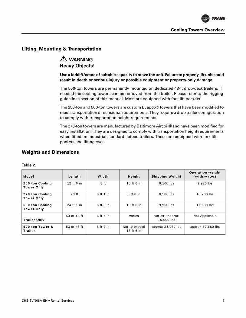
Lifting, Mounting & Transportation
� WARNING
Heavy Objects!
Use a forklift/crane of suitable capacity to move the unit. Failure to properly lift unit could
result in death or serious injury or possible equipment or property-only damage.
The 500-ton towers are permanently mounted on dedicated 48-ft drop-deck trailers. If needed the cooling towers can be removed from the trailer. Please refer to the rigging guidelines section of this manual. Most are equipped with fork lift pockets.
The 250-ton and 500-ton towers are custom Evapco® towers that have been modified to meet transportation dimensional requirements. They require a drop trailer configuration to comply with transportation height requirements.
The 270-ton towers are manufactured by Baltimore Aircoil® and have been modified for easy installation. They are designed to comply with transportation height requirements when fitted on industrial standard flatbed trailers. These are equipped with fork lift pockets and lifting eyes.
Weights and Dimensions
Table 2.
Model Length Width Height Shipping WeightOperation weight
(with water)
250 ton Cooling Tower Only
12 ft 6 in 8 ft 10 ft 6 in 6,100 lbs 9,975 lbs
270 ton Cooling Tower Only
20 ft 8 ft 1 in 8 ft 8 in 6,500 lbs 10,700 lbs
500 ton Cooling Tower Only
24 ft 1 in 8 ft 3 in 10 ft 6 in 9,960 lbs 17,680 lbs
Trailer Only53 or 48 ft 8 ft 6 in varies varies - approx
15,000 lbsNot Applicable
500 ton Tower & Trailer
53 or 48 ft 8 ft 6 in Not to exceed 13 ft 6 in
approx 24,960 lbs approx 32,680 lbs
8 Rental Services • CHS-SVN08A-EN
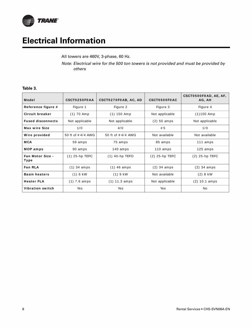
Electrical Information
All towers are 460V, 3-phase, 60 Hz.
Note: Electrical wire for the 500 ton towers is not provided and must be provided by others
Table 3.
Model CSCT0250F0AA CSCT0270F0AB, AC, AD CSCT0500F0ACCSCT0500F0AD, AE, AF,
AG, AH
Reference figure # Figure 1 Figure 2 Figure 3 Figure 4
Circuit breaker (1) 70 Amp (1) 150 Amp Not applicable (1)100 Amp
Fused disconnects Not applicable Not applicable (2) 50 amps Not applicable
Max wire Size 1/0 4/0 #5 1/0
Wire provided 50 ft of #4/4 AWG 50 ft of #4/4 AWG Not available Not available
MCA 59 amps 75 amps 85 amps 111 amps
MOP amps 90 amps 140 amps 110 amps 125 amps
Fan Motor Size - Type
(1) 25-hp TEFC (1) 40-hp TEFO (2) 25-hp TEFC (2) 25-hp TEFC
Fan RLA (1) 34 amps (1) 46 amps (2) 34 amps (2) 34 amps
Basin heaters (1) 6 kW (1) 9 kW Not available (2) 8 kW
Heater FLA (1) 7.6 amps (1) 11.3 amps Not applicable (2) 10.1 amps
Vibration switch Yes Yes Yes No
CHS-SVN08A-EN • Rental Services 9
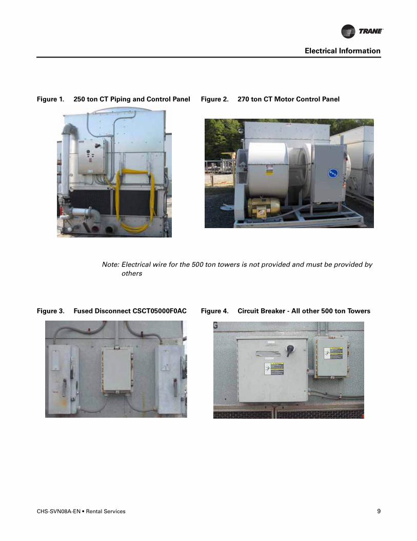
Electrical Information
Note: Electrical wire for the 500 ton towers is not provided and must be provided by others
Figure 1. 250 ton CT Piping and Control Panel Figure 2. 270 ton CT Motor Control Panel
Figure 3. Fused Disconnect CSCT05000F0AC Figure 4. Circuit Breaker - All other 500 ton Towers
10 Rental Services • CHS-SVN08A-EN
Piping Configurations
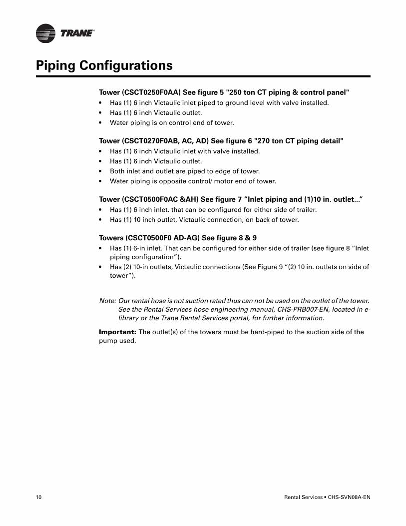
Tower (CSCT0250F0AA) See figure 5 "250 ton CT piping & control panel"
• Has (1) 6 inch Victaulic inlet piped to ground level with valve installed.
• Has (1) 6 inch Victaulic outlet.
• Water piping is on control end of tower.
Tower (CSCT0270F0AB, AC, AD) See figure 6 "270 ton CT piping detail"
• Has (1) 6 inch Victaulic inlet with valve installed.
• Has (1) 6 inch Victaulic outlet.
• Both inlet and outlet are piped to edge of tower.
• Water piping is opposite control/ motor end of tower.
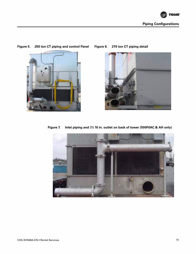
Tower (CSCT0500F0AC &AH) See figure 7 “Inlet piping and (1)10 in. outlet...”
• Has (1) 6 inch inlet. that can be configured for either side of trailer.
• Has (1) 10 inch outlet, Victaulic connection, on back of tower.
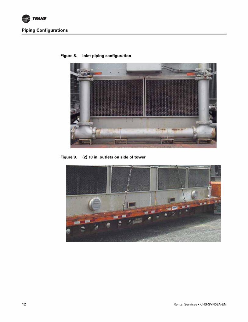
Towers (CSCT0500F0 AD-AG) See figure 8 & 9
• Has (1) 6-in inlet. That can be configured for either side of trailer (see figure 8 “Inlet piping configuration”).
• Has (2) 10-in outlets, Victaulic connections (See Figure 9 “(2) 10 in. outlets on side of tower”).
Note: Our rental hose is not suction rated thus can not be used on the outlet of the tower. See the Rental Services hose engineering manual, CHS-PRB007-EN, located in e-library or the Trane Rental Services portal, for further information.
Important: The outlet(s) of the towers must be hard-piped to the suction side of the pump used.
CHS-SVN08A-EN • Rental Services 11
Piping Configurations
Figure 5. 250 ton CT piping and control Panel Figure 6. 270 ton CT piping detail
Figure 7. Inlet piping and (1) 10 in. outlet on back of tower (500F0AC & AH only)
12 Rental Services • CHS-SVN08A-EN
Piping Configurations
Figure 8. Inlet piping configuration
Figure 9. (2) 10 in. outlets on side of tower
CHS-SVN08A-EN • Rental Services 13
Piping Configurations
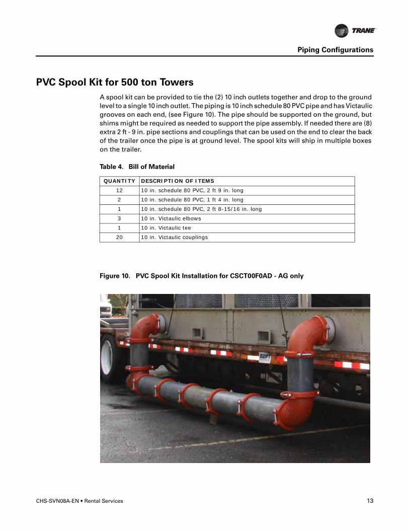
PVC Spool Kit for 500 ton Towers
A spool kit can be provided to tie the (2) 10 inch outlets together and drop to the ground level to a single 10 inch outlet. The piping is 10 inch schedule 80 PVC pipe and has Victaulic grooves on each end, (see Figure 10). The pipe should be supported on the ground, but shims might be required as needed to support the pipe assembly. If needed there are (8) extra 2 ft - 9 in. pipe sections and couplings that can be used on the end to clear the back of the trailer once the pipe is at ground level. The spool kits will ship in multiple boxes on the trailer.
Table 4. Bill of Material
QUANTITY DESCRIPTION OF ITEMS
12 10 in. schedule 80 PVC, 2 ft 9 in. long
2 10 in. schedule 80 PVC, 1 ft 4 in. long
1 10 in. schedule 80 PVC, 2 ft 8-15/16 in. long
3 10 in. Victaulic elbows
1 10 in. Victaulic tee
20 10 in. Victaulic couplings
Figure 10. PVC Spool Kit Installation for CSCT00F0AD - AG only
14 Rental Services • CHS-SVN08A-EN
Rigging Guidelines
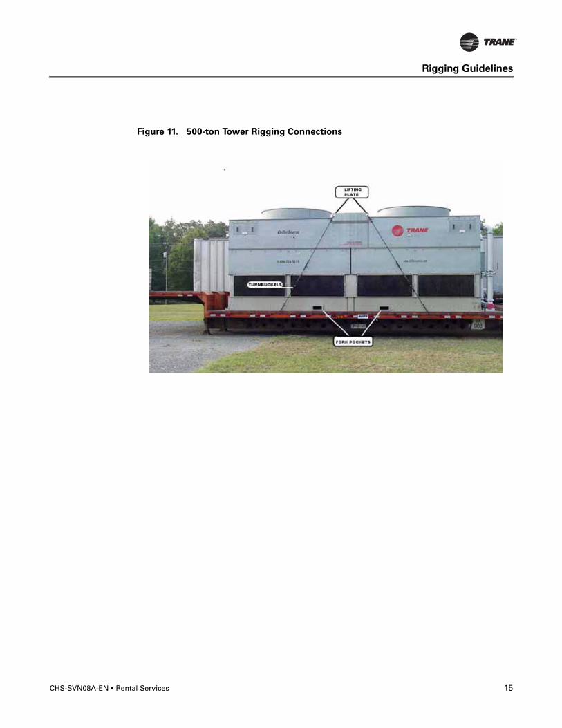
Each tower (except for - CSCT0500F0AC) has forklift pockets. This tower (CSCT0500F0AC) can only be removed by using the lifting plates (see figure 11).
� WARNING
Heavy Objects!
Use a forklift/crane of suitable capacity to move the unit. Failure to properly lift unit
could result in death or serious injury or possible equipment or property-only damage.
General Guidelines (not applicable to all models and sizes)1. If tower is removed from trailer, the foundation on which the tower will be operating
from must be able to support at least the operating weight of the tower. If left on the trailer, the weight of the trailer and the operating weight will be concentrated on the landing gear and tires. Provide cribbing or weight distribution plates as might be necessary for ground conditions.
2. If applicable, when tower is removed from trailer, mark the exact location of tower on trailer so it can be replaced in same location and with outlet water connections on the same side of the trailer. The trailer must be returned in the same condition in which it was delivered.
3. Lifting plates are located on each side of the top of the 500-ton towers. Fork pockets are located in the base of the tower (except tower 500F0AC). Lifting eyes are located on each side of the bottom of the 270 ton towers.
4. Drain, clean basin, and disconnect any piping and wiring before returning unit to trailer. 500 ton dual outlet towers should be positioned with 10" outlet connections on passenger side of trailer.
5. When tower is reloaded and in the same position, as when it was originally removed from the trailer, reconnect turnbuckles and tighten to secure to trailer.
CHS-SVN08A-EN • Rental Services 15
Rigging Guidelines
Figure 11. 500-ton Tower Rigging Connections
16 Rental Services • CHS-SVN08A-EN
Line Drawings
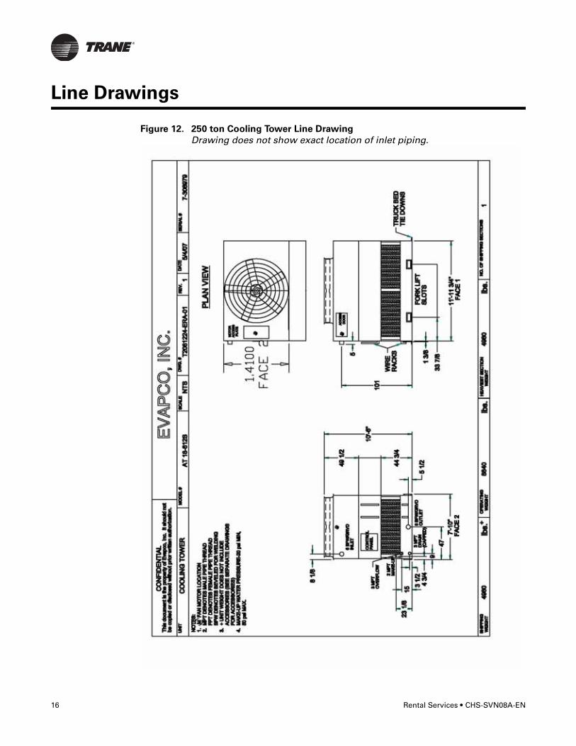
Figure 12. 250 ton Cooling Tower Line Drawing
Drawing does not show exact location of inlet piping.
CHS-SVN08A-EN • Rental Services 17
Line Drawings
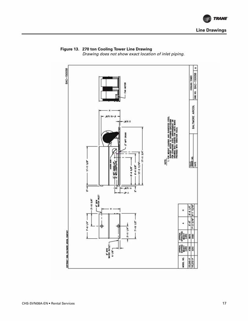
Figure 13. 270 ton Cooling Tower Line Drawing
Drawing does not show exact location of inlet piping.

18 Rental Services • CHS-SVN08A-EN
Line Drawings
Figure 14. 500 ton Cooling Tower Line Drawing (single outlet configuration)
CHS-SVN08A-EN • Rental Services 19
Startup Guidelines
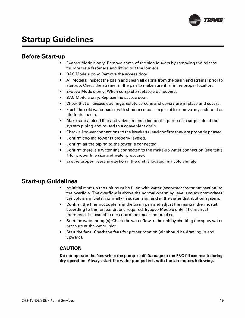
Before Start-up• Evapco Models only: Remove some of the side louvers by removing the release
thumbscrew fasteners and lifting out the louvers.
• BAC Models only: Remove the access door
• All Models: Inspect the basin and clean all debris from the basin and strainer prior to start-up. Check the strainer in the pan to make sure it is in the proper location.
• Evapco Models only: When complete replace side louvers.
• BAC Models only: Replace the access door.
• Check that all access openings, safety screens and covers are in place and secure.
• Flush the cold water basin (with strainer screens in place) to remove any sediment or dirt in the basin.
• Make sure a bleed line and valve are installed on the pump discharge side of the system piping and routed to a convenient drain.
• Check all power connections to the breaker(s) and confirm they are properly phased.
• Confirm cooling tower is properly leveled.
• Confirm all the piping to the tower is connected.
• Confirm there is a water line connected to the make-up water connection (see table 1 for proper line size and water pressure).
• Ensure proper freeze protection if the unit is located in a cold climate.
Start-up Guidelines• At initial start-up the unit must be filled with water (see water treatment section) to
the overflow. The overflow is above the normal operating level and accommodates the volume of water normally in suspension and in the water distribution system.
• Confirm the thermocouple is in the basin pan and adjust the manual thermostat according to the run conditions required. Evapco Models only: The manual thermostat is located in the control box near the breaker.
• Start the water pump(s). Check the water flow to the unit by checking the spray water pressure at the water inlet.
• Start the fans. Check the fans for proper rotation (air should be drawing in and upward).
CAUTION
Do not operate the fans while the pump is off. Damage to the PVC fill can result during
dry operation. Always start the water pumps first, with the fan motors following.
20 Rental Services • CHS-SVN08A-EN
Maintenance Guidelines
� WARNING
Hazardous Voltage!
Disconnect all electric power, including remote disconnects before servicing. Follow
proper lockout/tagout procedures to ensure the power can not be inadvertently
energized. Failure to disconnect power before servicing could result in death or serious
injury
Maintenance Guidelines
• Ensure proper chemical water treatment and bleed all of the air out of the system. See the water treatment recommendations below.
• Before beginning any maintenance, be certain that the power is turned off and the tower is properly locked and tagged out.
• Inspect the basin strainer and clean weekly or as often as necessary to keep it clean.
• Check the float and float valve periodically to make sure the water level is correct in the basin. The water level can be checked during operation by opening the removable louver section at the valve while the pump is running and the fans are off.
• Inspect the air louvers periodically to remove any paper, leaves, or other debris that may be blocking airflow into the unit.
Water Treatment Recommendations
To avoid build-up of residuals in the water distribution system, water must be bled off from the system in an amount equal to the rate of evaporation. In addition, water quality should be checked to ensure that the chemistry is balanced and that the water system is free from biological contamination.
It is recommended the system has a bleed line installed on the discharge side of the system pump and should include a metering connection and valve. The metering connection should be used to determine the bleed water volume. The valve is used to regulate the flow. As a guideline, the bleed line and valve should be large enough to allow bleed off of an amount of water equal to 3 US gpm for each 100 tons cooling or use the formula Bleed (gpm) = Flow (gpm) x Range (F) / 1,000. Confirm with your water treatment specialist to confirm the required bleed off for your system.
In some cases, the make-up water will be so high in mineral content that a normal bleed-off will not prevent scaling. Water treatment will be required and qualified water treatment company familiar with the local water conditions should be consulted. Any water treatment system used in the unit must be compatible with the unit’s materials of construction. If a chemical water treatment system is used, the chemicals selected must be accurately metered and concentrations properly controlled. See Table 5 for recommended levels.
CHS-SVN08A-EN • Rental Services 21
Maintenance Guidelines
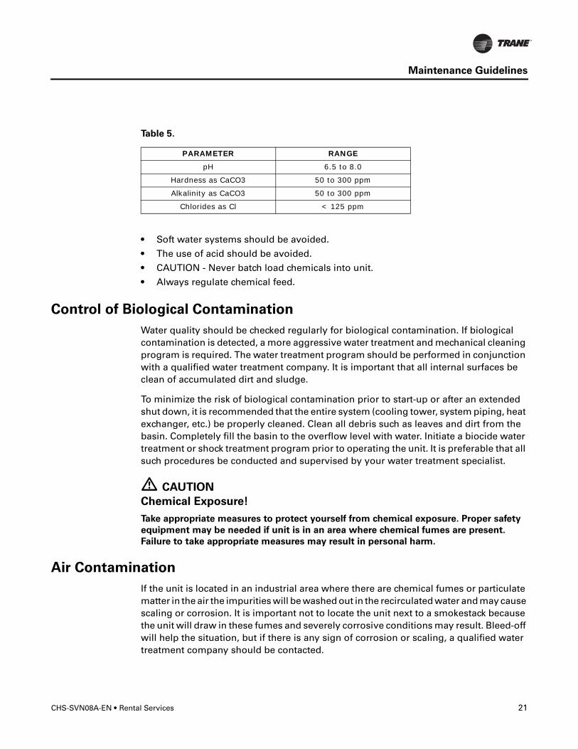
• Soft water systems should be avoided.
• The use of acid should be avoided.
• CAUTION - Never batch load chemicals into unit.
• Always regulate chemical feed.
Control of Biological Contamination
Water quality should be checked regularly for biological contamination. If biological contamination is detected, a more aggressive water treatment and mechanical cleaning program is required. The water treatment program should be performed in conjunction with a qualified water treatment company. It is important that all internal surfaces be clean of accumulated dirt and sludge.
To minimize the risk of biological contamination prior to start-up or after an extended shut down, it is recommended that the entire system (cooling tower, system piping, heat exchanger, etc.) be properly cleaned. Clean all debris such as leaves and dirt from the basin. Completely fill the basin to the overflow level with water. Initiate a biocide water treatment or shock treatment program prior to operating the unit. It is preferable that all such procedures be conducted and supervised by your water treatment specialist.
� CAUTION
Chemical Exposure!
Take appropriate measures to protect yourself from chemical exposure. Proper safety
equipment may be needed if unit is in an area where chemical fumes are present.
Failure to take appropriate measures may result in personal harm.
Air Contamination
If the unit is located in an industrial area where there are chemical fumes or particulate matter in the air the impurities will be washed out in the recirculated water and may cause scaling or corrosion. It is important not to locate the unit next to a smokestack because the unit will draw in these fumes and severely corrosive conditions may result. Bleed-off will help the situation, but if there is any sign of corrosion or scaling, a qualified water treatment company should be contacted.
Table 5.
PARAMETER RANGE
pH 6.5 to 8.0
Hardness as CaCO3 50 to 300 ppm
Alkalinity as CaCO3 50 to 300 ppm
Chlorides as Cl < 125 ppm

www.trane.com
For more information, contact your local Trane office or e-mail us at [email protected]
Literature Order Number CHS-CVN08A-EN
Date July 2008
Supersedes CHS-PRB008-EN March 2007
Trane has a policy of continuous product and product data improvement and reserves the right to change design and specifications without notice.