coolplug coolinkhub hvac bridge quick installation guide · 2019-09-19 · coolplug coolinkhub hvac...
TRANSCRIPT

CoolPlug CooLinkHUB HVAC Bridge
Quick Installation Guide
Version 2.2
11/07/19
Document Number: 2.2
Contact information: [email protected]
HVAC Control Made Simple

CoolPlug CooLinkHUB HVAC Bridge CooLinkHUB + CoolPlug
QIG Version 2.2 2 CoolPlug CooLinkHUB
Table of Contents 1. CooLinkHUB + CoolPlug ............................................................................................... 5
1.1 System Overview ............................................................................................... 5
1.2 Network Topology .............................................................................................. 5
1.3 CoolPlug Models ................................................................................................ 5
1.4 What’s in the box ................................................................................................ 6
2. Connecting CoolPlug .................................................................................................... 7
2.1 DK (Daikin) – S21 ............................................................................................... 7
3. Connecting CoolPlug DK (Daikin) ................................................................................. 8
3.1 DK (Daikin) – P1 P2 ........................................................................................... 8
4. Connecting CoolPlug DKS ............................................................................................ 9
4.1 DK (Daikin) – Siesta Series ................................................................................ 9
5. Connecting CoolPlug PN/SA/TO ................................................................................. 10
5.1 Panasonic | Sanyo | Toshiba ............................................................................ 10
6. Connecting CoolPlug FJ .............................................................................................. 11
6.1 FJ (Fujitsu/General) - Option 1* ........................................................................ 11
6.2 FJ (Fujitsu/General) - Option 2* ........................................................................ 12
6.3 FJ (Fujitsu/General) - Option 3* ........................................................................ 13
7. Connecting CoolPlug ME (Mitsubishi Electric) ............................................................. 14
7.1 Option 1 – CN-105 ........................................................................................... 14
8. Connecting CoolPlug MH (Mitsubishi Heavy) .............................................................. 15
8.1 Option 2 – [1] [2] ............................................................................................... 15
9. Connecting CoolPlug HT (Hitachi) ............................................................................... 16
10. Connecting CoolPlug LG (LG) ..................................................................................... 17
11. Connecting CoolPlug Gree (GRTS)............................................................................. 18
11.1 Gree Option 1 ................................................................................................... 18
11.2 Gree Option 2 ................................................................................................... 19
11.3 Gree Option 3 (H1,H2) ..................................................................................... 20
12. Connecting Home Automation, BMS & CoolRemote ................................................... 21
13. CoolRemote App ......................................................................................................... 22
14. CoolPlug Operation ..................................................................................................... 23
14.1 CoolPlug Indicators .......................................................................................... 23
14.2 CoolPlug Normal Operation .............................................................................. 23
15. Wireless CoolPlug & CooLinkHUB – Installation Guidelines ........................................ 25
15.1 Rebuilding the wireless mesh network .............................................................. 26
16. Mounting the CoolPlug ................................................................................................ 27

CoolPlug CooLinkHUB HVAC Bridge CooLinkHUB + CoolPlug
QIG Version 2.2 3 CoolPlug CooLinkHUB
Safety Guidelines, Warnings and Cautions Read and understand the following guidelines to ensure a safe installation.
Warnings
Failure to follow WARNING may result in injury or death.
This equipment is to be installed by an accredited electrician or equivalent technical
person, as per these installation instructions.
Read the installation instructions before connecting the system to the power source.
All electrical work must be performed by a licensed technician, according to local regulations.
Ultimate disposal of this product should be handled according to all national laws and
regulations.
Installation of the equipment must comply with local and national electrical legislation for
installation of electric equipment.
Do not install the devices outdoors or exposed to direct solar radiation, water, high relative
humidity or dust.
Install the equipment only in a restricted access location.
When wall mounting, be sure to fix firmly on a stable surface and in accordance to the
instructions below.
When DIN rail mounting, fix the devices properly to the DIN rail following the instructions
below.
When mounting on DIN rail inside a metallic cabinet be sure to properly connect to earth.
Unplug power when connecting the wires.
Pay attention to the polarity of power and communication cables when connecting them.
Disconnect power of any bus or communication cable before connecting the system.
Cautions
Failure to follow CAUTION may result in serious injury.
Do not allow children to play with the CoolPlug or CooLinkHUB.
Do not disassemble, modify or repair the CoolPlug or CooLinkHUB, do contact
CoolAutomation for support. Unauthorized modifications or repairs may result in electric
shock or fire.
Do not expose the CoolPlug or CooLinkHUB to moisture. Water can damage the
CoolPlug or CooLinkHUB resulting in an electrical components failure, electric shock or
fire.

CoolPlug CooLinkHUB HVAC Bridge CooLinkHUB + CoolPlug
QIG Version 2.2 4 CoolPlug CooLinkHUB
Do not use flammable materials (e.g. hairspray or insecticide) near the CoolPlug or
CooLinkHUB. Do not clean the CoolPlug or CooLinkHUB with organic solvents such as
paint thinner.
Use only a dry cloth to wipe if necessary. The maximum voltage that can be directly
applied to the CooLinkHUB is 24V DC. Do not apply AC110V or AC220V to the
CooLinkHUB or CoolPlug.
DO NOT INSTALL the COOLINKHUB or COOLPLUG IN THE FOLLOWING
LOCATIONS:
a) Where mineral oil mist or oil spray or vapor is produced, for example, in a kitchen.
Plastic parts may deteriorate and fall off.
b) Where corrosive gas, such as sulfurous acid gas, is produced.
c) Near machinery emitting electromagnetic waves. Electromagnetic waves may
disturb or damage the operation of the CooLinkHUB.
d) Where flammable gas may leak, where there is carbon fiber or ignitable dust
suspensions in the air, or where volatile flammables such as thinner or gasoline are
handled. Operating the CooLinkHUB or CoolPlug in such conditions may cause a
fire.
e) In high temperature areas or near any flame.
f) In moist areas, or where there is exposure to water.

CoolPlug CooLinkHUB HVAC Bridge CooLinkHUB + CoolPlug
QIG Version 2.2 5 CoolPlug CooLinkHUB
1. CooLinkHUB + CoolPlug
1.1 System Overview
The CooLinkHUB + CoolPlug is a solution for complete integration of Multi-Split and Mini-
Split HVAC units. The CoolPlug - HVAC designated adapter, connects directly to the HVAC
indoor unit on one side, and to the CooLinkHUB on the other, via a PBUS Network.
The CooLinkHUB - protocol converter allows integration to any Home Automation system.
1.2 Network Topology
The PBUS is a Cool Automation’s proprietary Bus, running on a shielded twisted pair cable
(24AWG). The PBUS utilizes free network topology (‘star’, ‘daisy- chain’, etc.) No loops allowed.
Up to 10 CoolPlugs can be connected in a single PBUS network.
1.3 CoolPlug Models
CoolPlug models are HVAC manufacturer specific. The letters on the sticker (DK, DKS, etc.)
indicate the HVAC manufacturer the CoolPlug relates to.

CoolPlug CooLinkHUB HVAC Bridge CooLinkHUB + CoolPlug
QIG Version 2.2 6 CoolPlug CooLinkHUB
1.4 What’s in the box
1.4.1 CooLinkHUB
▪ CooLinkHUB Unit
▪ USB cable
▪ RS-232 cable
▪ Power supply
(Universal or EU – according to SN)
1.4.2 CoolPlug
▪ CoolPlug Unit
▪ CoolPlug back plate for adding two magnets
▪ CoolPlug back plate for adding two stamps
▪ Two stamps
▪ Two magnets
▪ Optional: Terminal cable
(according to the specific plug model as indicated on the above table.

CoolPlug CooLinkHUB HVAC Bridge Connecting CoolPlug
QIG Version 2.2 7 CoolPlug CooLinkHUB
2. Connecting CoolPlug
2.1 DK (Daikin) – S21
1 Connecting the CoolPlug to the Daikin unit
Connect the S21 cable supplied with the CoolPlug, between the CoolPlug RJ-11
connector and the S21 port on the indoor unit’s PCB. Consult HVAC manufacturer’s
installation manual for location of S21 on Control Board.
2 Connecting the CoolPlug to the CooLinkHUB
Connect the signal wires of the PBUS cable between CoolPlug terminals [-], [1] and
[2], and CooLinkHUB terminals [VDC-], [1] and [2], respectively.
* See page 5 for system overview, no point-to-point connectivity required.

CoolPlug CooLinkHUB HVAC Bridge Connecting CoolPlug DK (Daikin)
QIG Version 2.2 8 CoolPlug CooLinkHUB
3. Connecting CoolPlug DK (Daikin)
3.1 DK (Daikin) – P1 P2
1 Connecting the CoolPlug to the Daikin unit
Connect the CoolPlug’s [P1], [P2] terminals to the [P1], [P2] terminals on the indoor
unit.*
2 Connecting the CoolPlug to the CooLinkHUB
Connect the signal wires of the PBUS cable coming from the [VDC-], [1] and [2]
terminals on the CooLinkHUB to the corresponding [-], [1] and [2] terminals on the
CoolPlug, respectively.
Optional: Connect the Wired Remote Controller (W.R.C.) in parallel mode.
* No Polarity requirements

CoolPlug CooLinkHUB HVAC Bridge Connecting CoolPlug DKS
QIG Version 2.2 9 CoolPlug CooLinkHUB
4. Connecting CoolPlug DKS
4.1 DK (Daikin) – Siesta Series
1 Connecting the CoolPlug HVAC Line to the Daikin Siesta Indoor Unit
Connect the cable, supplied with the CoolPlug, to the port labeled “Indoor” on CoolPlug
and the corresponding connector on the indoor unit.
2 Connecting the CoolPlug to the CooLinkHUB
Connect the signal wires of the PBUS cable, using [VDC-], [1] and [2] terminals on the
CooLinkHUB, to the corresponding [-], [1] and [2] terminals on the CoolPlug.
3 Optional: Connect the wired remote to the ‘W.R.C’ socket on the CoolPlug. The
cable is supplied with the W.R.C.

CoolPlug CooLinkHUB HVAC Bridge Connecting CoolPlug PN/SA/TO
QIG Version 2.2 10 CoolPlug CooLinkHUB
5. Connecting CoolPlug PN/SA/TO
5.1 Panasonic | Sanyo | Toshiba
1 Connecting the CoolPlug HVAC Line to the PN/SA/TO Indoor Unit
Connect the CoolPlug’s [A], [B] terminals to [A], [B] terminals on indoor unit.
* To connect to Panasonic indoor unit, use R1 R2 terminals.
2 Connecting the CoolPlug to the CooLinkHUB
Connect the signal wires of the PBUS cable coming from the [VDC-], [1] and [2]
terminals on the CooLinkHUB to the corresponding [-], [1] and [2] terminals on the
CoolPlug.
3 Optional: Connect the Wired Remote Controller (W.R.C.).

CoolPlug CooLinkHUB HVAC Bridge Connecting CoolPlug FJ
QIG Version 2.2 11 CoolPlug CooLinkHUB
6. Connecting CoolPlug FJ
6.1 FJ (Fujitsu/General) - Option 1*
1 Connecting the CoolPlug HVAC Line to the Fujitsu Indoor Unit
Connect the CoolPlug’s [W1], [B1], [R1] terminals to corresponding terminals on the
indoor unit, keeping the wire colors consistency.
2 Connecting the CoolPlug to the CooLinkHUB
Connect the signal wires of the PBUS cable, using the [VDC-], [1] and [2] terminals on
the CooLinkHUB, to the corresponding [-], [1] and [2] terminals on the CoolPlug.
3 Optional: Connect the Wired Remote Controller (W.R.C.)
* For indoors that work with APG000 or compatible W.R.C. models.
* Reset power, once the CoolPlug is installed

CoolPlug CooLinkHUB HVAC Bridge Connecting CoolPlug FJ
QIG Version 2.2 12 CoolPlug CooLinkHUB
6.2 FJ (Fujitsu/General) - Option 2*
1 Connecting the CoolPlug to the CooLinkHUB
Connect the signal wires of the PBUS cable coming from the [VDC-], [1] and [2]
terminals on the CooLinkHUB to the corresponding [-], [1] and [2] terminals on the
CoolPlug.
2 Connecting the CoolPlug HVAC Line to the Fujitsu Indoor Unit
Connect the CoolPlug’s [W1], [B1], [R1] terminals to indoor unit. Consult HVAC
manufacturer’s Installation Manual for instructions.
3 Optional: Connect the CoolPlug’s [W2], [B2], [R2] terminals to the Fujitsu Wired Remote
Controller (W.R.C.)
* For indoors that work with EZ-099 or compatible type wired remote controllers.
* Reset power, once the CoolPlug is installed

CoolPlug CooLinkHUB HVAC Bridge Connecting CoolPlug FJ
QIG Version 2.2 13 CoolPlug CooLinkHUB
6.3 FJ (Fujitsu/General) - Option 3*
1 Connecting the CoolPlug HVAC Line to the Fujitsu Indoor Unit
Connect the CoolPlug’s [W1], [B1], [R1] terminals to the corresponding terminals on the
indoor unit, keeping the wire colors consistent.
2 Connecting the CoolPlug to the CooLinkHUB
Connect the signal wires of the PBUS cable, using the [VDC-], [1] and [2] terminals on
the CooLinkHUB, to the corresponding [-], [1] and [2] terminals on the CoolPlug.
3 Optional: Connect the Wired Remote Controller (W.R.C.)
* For indoors that work with 2-wire compatible W.R.C. models.

CoolPlug CooLinkHUB HVAC Bridge Connecting CoolPlug ME (Mitsubishi Electric)
QIG Version 2.2 14 CoolPlug CooLinkHUB
7. Connecting CoolPlug ME (Mitsubishi Electric)
7.1 Option 1 – CN-105
1 Connecting the CoolPlug HVAC Line to the Mitsubishi Indoor Unit
Connect the ME CN-105 cable, supplied with the CoolPlug, between the CoolPlug RJ-
11 connector and the CN-105 port on the indoor unit’s Control Board. Consult the HVAC
manufacturer’s installation manual for the location of the CN-105 port on the Control
Board.
2 Connecting the CoolPlug to the CooLinkHUB
Connect the signal wires of the PBUS cable, using the [VDC-], [1] and [2] terminals on
the CooLinkHUB, to the corresponding [-], [1] and [2] terminals on the CoolPlug.

CoolPlug CooLinkHUB HVAC Bridge Connecting CoolPlug MH (Mitsubishi Heavy)
QIG Version 2.2 15 CoolPlug CooLinkHUB
8. Connecting CoolPlug MH (Mitsubishi Heavy)
8.1 Option 2 – [1] [2]
1 Connecting the CoolPlug HVAC Line to the Mitsubishi Indoor Unit
Connect the CoolPlug’s HVAC [1], HVAC [2] terminals to the [1], [2] terminals on the
indoor unit. Consult the HVAC manufacturer’s installation manual for the location of the
[1] and [2] terminals.
2 Connecting the CoolPlug to the CooLinkHUB
Connect the signal wires of the PBUS cable, using the [VDC-], [1] and [2] terminals on
the CooLinkHUB to the corresponding [-], [1] and [2] terminals on the CoolPlug.
3 Optional: Connect the Wired Remote Controller (W.R.C.).

CoolPlug CooLinkHUB HVAC Bridge Connecting CoolPlug HT (Hitachi)
QIG Version 2.2 16 CoolPlug CooLinkHUB
9. Connecting CoolPlug HT (Hitachi)
1 Connecting the CoolPlug to the Hitachi unit
Connect the CoolPlug’s HVAC [1], [2] terminals to the [1], [2] terminals on the indoor
unit.
2 Connecting the CoolPlug to the CooLinkHUB
Connect the signal wires of the PBUS cable coming from the [VDC-], [1] and [2]
terminals on the CooLinkHUB to the corresponding [-], [1] and [2] terminals on the
CoolPlug.
3 Optional: Connect the Wired Remote Controller (W.R.C.).

CoolPlug CooLinkHUB HVAC Bridge Connecting CoolPlug LG (LG)
QIG Version 2.2 17 CoolPlug CooLinkHUB
10. Connecting CoolPlug LG (LG)
1 Connecting the CoolPlug to the Indoor unit
Connect the cable supplied with the CoolPlug, between the CoolPlug HVAC [Y], [B],
[R] terminals and the port on the indoor unit’s PCB. Consult the HVAC
manufacturer’s installation manual.
2 Connecting the CoolPlug to the CooLinkHUB
Connect the signal wires of the PBUS cable between CoolPlug terminals [-], [1] and [2],
and CooLinkHUB terminals [VDC-], [1] and [2], respectively.
3 Optional: Connect the Wired Remote Controller (W.R.C.) in parallel mode.

CoolPlug CooLinkHUB HVAC Bridge Connecting CoolPlug Gree (GRTS)
QIG Version 2.2 18 CoolPlug CooLinkHUB
11. Connecting CoolPlug Gree (GRTS)
11.1 Gree Option 1
1 Connecting the CoolPlug HVAC Line to the Gree Indoor Unit
Connect the cable supplied with the CoolPlug, between the CoolPlug Indoor connector and the connector on the indoor unit’s PCB. Consult the HVAC manufacturer’s Installation manual for the location of the indoor unit connector on the Control Board.
2 Connecting the CoolPlug to the W.R.C.
Connect the short cable (supplied with the CoolPlug) between the 2 W.R.C. ports and the W.R.C. cable to the CoolPlug’s W.R.C. port.
3 Connecting the CoolPlug to the CooLinkHUB
Connect the signal wires of PBUS cable between the CoolPlug terminals [-], [1] and [2], and the CooLinkHUB terminals [VDC-], [1] and [2], respectively.

CoolPlug CooLinkHUB HVAC Bridge Connecting CoolPlug Gree (GRTS)
QIG Version 2.2 19 CoolPlug CooLinkHUB
11.2 Gree Option 2
1 Connecting the CoolPlug HVAC line to the Gree Indoor Unit
Connect the cable supplied with the CoolPlug, between the CoolPlug Indoor connector
and the connector on the indoor unit’s cable. Consult HVAC manufacturer’s Installation
manual for location of indoor unit cable.
2 Connecting the CoolPlug to the W.R.C.
Connect the short cable (supplied with the CoolPlug) between the 2 W.R.C. ports.
Connect the W.R.C. cable to the connector of the adapter cable supplied with the CoolPlug. Then connect the CoolPlug adapter to the CoolPlug W.R.C. port.
3 Connecting the CoolPlug to the CooLinkHUB
Connect the signal wires of the PBUS network cable between CoolPlug terminals [-], [1] and [2], and CooLinkHUB terminals [VDC-], [1] and [2], respectively.

CoolPlug CooLinkHUB HVAC Bridge Connecting CoolPlug Gree (GRTS)
QIG Version 2.2 20 CoolPlug CooLinkHUB
11.3 Gree Option 3 (H1, H2)
1 Connecting the CoolPlug HVAC line to the Gree Indoor Unit
Connect the CoolPlug’s H1, H2 terminals to terminals H1 and H2 on the indoor unit.
Consult HVAC manufacturer’s Installation manual for location of terminals H1 and H2.
Note: W.R.C. can be connected to H1, H2 in parallel to the CoolPlug connection.
2 Connecting the CoolPlug to the CooLinkHUB
Connect the signal wires of the PBUS network cable, using [VDC-], [1] and [2] terminals
on the CooLinkHUB to the corresponding [-], [1] and [2] terminals on the CoolPlug.
CoolPlug CooLinkHUB HVAC Bridge Connecting Home Automation, BMS & CoolRemote
QIG Version 2.2 21 CoolPlug CooLinkHUB
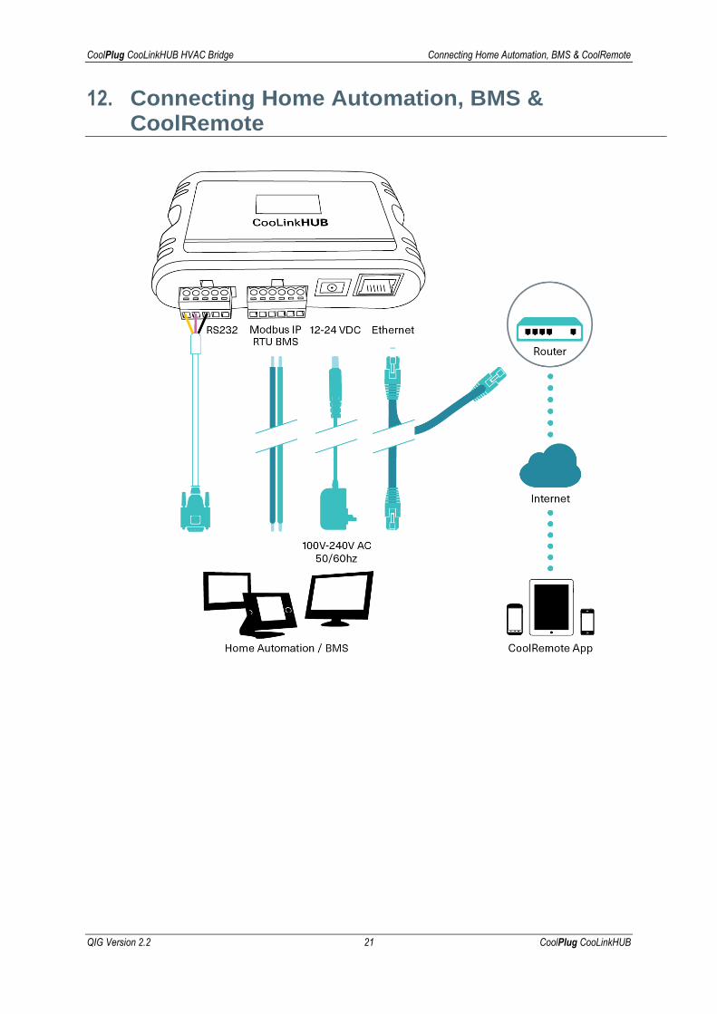
12. Connecting Home Automation, BMS & CoolRemote

CoolPlug CooLinkHUB HVAC Bridge CoolRemote App
QIG Version 2.2 22 CoolPlug CooLinkHUB
13. CoolRemote App
Connect the device to the Internet for registration and setup.
Option A – Automatic
1 Scan the QR code from the type label to auto fill-in all the CooLinkHUB details for the
CoolRemote App.
2 Register your username (email) and password to remotely control and monitor all your
HVAC units.
Option B – Manual
1 Go to: https://coolremote.net/register. Enter the CooLinkHUB SN number and PIN code,
printed on the sticker.
2 Register your username (email) and password to remotely control and monitor your
HVAC units.
CoolPlug CooLinkHUB HVAC Bridge CoolPlug Operation
QIG Version 2.2 23 CoolPlug CooLinkHUB
14. CoolPlug Operation
14.1 CoolPlug Indicators
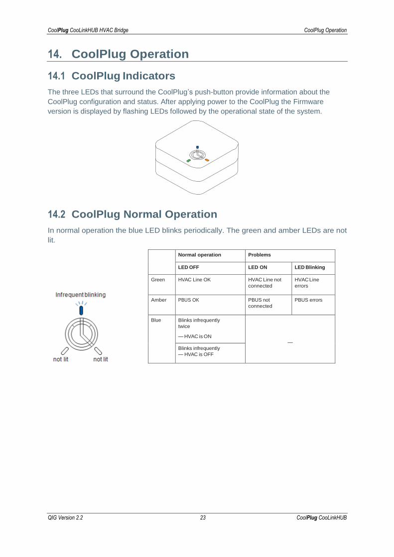
The three LEDs that surround the CoolPlug’s push-button provide information about the
CoolPlug configuration and status. After applying power to the CoolPlug the Firmware
version is displayed by flashing LEDs followed by the operational state of the system.
14.2 CoolPlug Normal Operation
In normal operation the blue LED blinks periodically. The green and amber LEDs are not
lit.
Normal operation Problems
LED OFF LED ON LED Blinking
Green HVAC Line OK HVAC Line not
connected
HVAC Line
errors
Amber PBUS OK PBUS not
connected
PBUS errors
Blue Blinks infrequently
twice
— HVAC is ON
—
Blinks infrequently
— HVAC is OFF

CoolPlug CooLinkHUB HVAC Bridge CoolPlug Operation
QIG Version 2.2 24 CoolPlug CooLinkHUB
Determining the CoolPlug UID
The CoolPlug UID is flashed after one ‘Short’ press on the CoolPlug push-button.
Toggling the HVAC ON/OFF
Toggle the HVAC state ON/OFF with one ‘Long’ press on the CoolPlug push-button.
Resetting the CoolPlug
Reset the CoolPlug with one ‘Short’ press followed by one ‘Continuous’ press on the CoolPlug push-button.
CoolPlug CooLinkHUB HVAC Bridge Wireless CoolPlug & CooLinkHUB – Installation Guidelines
QIG Version 2.2 25 CoolPlug CooLinkHUB
15. Wireless CoolPlug & CooLinkHUB – Installation Guidelines
Important Notes:
1 To successfully pair the CooLinkHUB to the CoolPlug they must be in line-of-sight
proximity one to the other (no more than three meters).
2 The CoolPlug is powered from the HVAC terminal. It can also be powered via USB
during the setup process (either from a PC or the CooLinkHUB).
3 The CooLinkHUB can connect simultaneously to both wired and wireless CoolPlug
units.
How to pair and connect a CoolPlug with the CooLinkHUB
1 On the CooLinkHUB, press the OK button.
2 An Option menu is displayed on the LCD screen.
3 With the up/down arrow buttons, select the Wireless option.
4 Press the OK button. A new options menu is displayed on the screen.
5 With the arrow buttons select the Pair option.
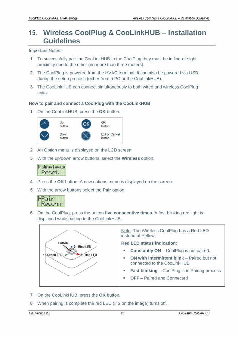
6 On the CoolPlug, press the button five consecutive times. A fast blinking red light is
displayed while pairing to the CooLinkHUB.
Note: The Wireless CoolPlug has a Red LED instead of Yellow.
Red LED status indication:
▪ Constantly ON – CoolPlug is not paired.
▪ ON with intermittent blink – Paired but not connected to the CooLinkHUB
▪ Fast blinking – CoolPlug is in Pairing process
▪ OFF – Paired and Connected
7 On the CooLinkHUB, press the OK button.
8 When pairing is complete the red LED (# 3 on the image) turns off.

CoolPlug CooLinkHUB HVAC Bridge Wireless CoolPlug & CooLinkHUB – Installation Guidelines
QIG Version 2.2 26 CoolPlug CooLinkHUB
9 When pairing is complete the CoolPlug immediately tries to connect to the CooLinkHUB.
10 Once the connection is successful, the number of connected CoolPlugs is displayed on
the screen in L5 GXXX, where XXX denotes a number (in the image below XXX=5).
11 The devices are now paired and connected.
15.1 Rebuilding the wireless mesh network
In some cases, rebuilding the mesh network topology may be required. For example, when
changing the position of a number of CoolPlugs.
To ensure the network is built in the most optimal way, follow the reconnection procedure:
To reconnect all paired devices to the wireless network mesh
1 On the CooLinkHUB, press the OK button. An options menu is displayed on the screen.
2 With the arrow buttons select the Wireless option.
3 Press the OK button. A new options menu is displayed on the screen.
4 With the arrow buttons select the Reconn option.
5 Press the OK button.
6 Upon successful reconnection, the expected number of CPs is displayed on the screen
in L5 GXXX (as in the image below).
Note: To reconnect devices, no actions need to be performed on the CoolPlug devices.

CoolPlug CooLinkHUB HVAC Bridge Mounting the CoolPlug
QIG Version 2.2 27 CoolPlug CooLinkHUB
16. Mounting the CoolPlug
On a Metal Surface
The CoolPlug back plate has two magnets that allow you to mount it on any metal surface.
On the Wall
Attach the CoolPlug back plate to the wall using screws as shown. The wires can be fed through the hole in the center of the cover or from the side as shown.
On DIN Rail
Use back plate for DIN rail to attach it to the DIN rail utilizing magnets.

CoolPlug CooLinkHUB HVAC Bridge Mounting the CoolPlug
QIG Version 2.2 28 CoolPlug CooLinkHUB
Need more help?
Visit us: https://coolautomation.com/support
HVAC Control Made Simple