copano bay bridge replacement · pdf filecopano bay bridge replacement . william ... upgrade a...
TRANSCRIPT
COPANO BAY BRIDGE REPLACEMENT
William H. Reitmann, P.E. Sinton Area Engineer

Copano Bridge Location
Located in Aransas County 45 miles North of Corpus Christi Upgrade a 2 mile bridge over
Copano Bay from a two lane roadway to a four lane roadway.
Cost $98,162,587 Contractor Williams Brothers
2

Existing Bridge Constructed 1967
3

Existing Bridge
9,232 ft. 229 spans 40 ft. average span length 2-13 ft. lanes with 2 ft. shoulders Outdated bridge rail 46 year old bridge
4
2001 94 piles encased. October 2009 Emergency Structure
repair.

Proposed Project
Construction began August 2011 4 years to complete Project Length 16,129 ft. or 3.054 mi. Bridge Length 11,010 ft. or 2.085 mi. Center Line of new bridge 40 ft. east of existing 93 Spans
– 92 spans of Tx54 in 120’ and 100’ lengths – 1 span of Tx70 at 150’ channel crossing
Girder Type TX54 (129,785 LF), TX70 (1,794 LF) 94 bents 460 round piles 54 in. (50,591 LF) 330 square piles 24 in. (27,844 LF) TY T223 Rail (22,665 LF) 42 in. Single Slope Concrete Barrier Type 1 (10655 LF) 42 in. Single Slope Concrete Barrier Type 4 (510 LF) 3% bridge grade over channel Maximum vertical clearance at channel 75 ft.
5
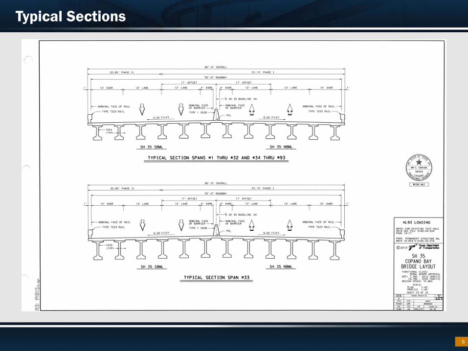
Typical Sections
6

Construction Phasing and Time Line
Phase I – 62 ft. – 3 years Demo Existing Bridge – 3 months Phase II – 18 ft. – 1 year
7

CONSTRUCTION ACTIVITIES

54 in. Cylindrical Concrete Piles
First time used in Texas. Range in length from 83 ft. – 157 ft.
9

Curing the Piles
10
54 in. cylindrical pile 46 – ½ in dia prestressing
strands W11 spiral wrap CL “H” Concrete (HPC) Compressive Strength 7000 psi
6 in. wall thickness 2 ⅜ in. clear cover

Initial Inspection of the Piles
11

Transporting the Piles
54 in. Cylindrical Pile Eagle Lake to Rockport (147 mi.)
12

Inspecting the Piles at the Job Site
13

Setting the Piles
14

The Hammer
Made by Pileco, Inc Cost $750,000 68,785 lbs
15

Cushion Blocks
16
15 in. thick

Vent Holes
17
3 in. vent holes Spaced at 3’-0”, 9’-9”, and 21’-0”

Preparing to Drive Test Piles
18

Test Pile Program
19
13 test piles Dynamic Monitoring and Analysis of Driven Piling
Special Spec 4586 – Conduct the Dynamic Pile Monitoring during initial
driving and any restrikes. – Use the Case Pile Wave Analysis Program and Wave
Equation analysis program to determine • Ultimate Pile Bearing Capacity • Pile stresses • Pile integrity • Pile driving system efficiency • Pile length

Test Piles
20

21

Concrete Plant
22

Concrete on Barge
23

High Performance Concrete
Type C HPC – Design Strength Min 28 day 3600 psi – Used for
• Bridge abutments • Bridge bents • Bridge footings
Type S HPC – Design Strength Min 28 day 4000 psi – Used for
• Bridge slab
Type H HPC – Design Strength Min 28 day 7000 psi – Used for
• Beams • Piles
Corrosion inhibiting admixtures – Calcium nitrate 3 gals/cy
24

Epoxy-Coated Reinforcing (ECR) Steel
Used in – Deck – Rail – Abutments – Bent caps and tie-beams – Columns
25

Stainless Reinforcing Steel
“Splash Zone” below El 13 ft. – MHW = El 1 ft. – Plus 12 ft. wave height
Cost stainless $2.47/lb compare to black $0.35/ lb Use stainless reinforcing steel
in CIP elements – Columns – Footings – Pile-footing connections
26
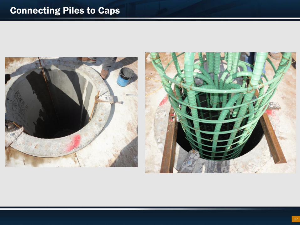
Connecting Piles to Caps
27

Cap Connection
28

Forming the Caps
29

30

Finished Caps
31

Cracked Piles
32

33

34

35

36

Currently working on Phase 1 85899 SF slab complete to date 17% complete (16 spans)
37

20 completed bent caps
38

The Piles So Far in Phase 1
100% of 24 in piles completed 91% of 54 in piles completed
39

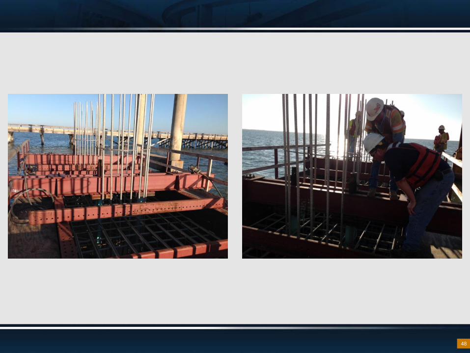
Footing Pile Connections
40

Footing Pile Connections
41

Footing Pile Connections
42

Footing Pile Connections
43

Footing Pile Connections
44

Footing Pile Connections
45

46

47
48

49

50

Construction Continues
51