copper boilers instruction manual for hydronic heating …
TRANSCRIPT

1
Thank You
PRINTED 0809 212130-002
COPPER BOILERSFOR HYDRONIC HEATINGAND HOT WATER SUPPLY
CAUTIONTEXT PRINTED OR OUTLINED IN RED CONTAINSINFORMATION RELATIVE TO YOUR SAFETY. PLEASEREAD THOROUGHLY BEFORE INSTALLING AND USINGTHIS APPLIANCE.
PLACE THESE INSTRUCTIONS ADJACENT TO BOILER AND NOTIFY OWNER TO KEEP FOR FUTURE REFERENCE.
GB/GW-300, 400, 500, 650, 750SERIES 400, 401, 402, 403, 404, 405
2-STAGE UNITS
for buying this cost efficient, high recovery unit from A. O. Smith Water Products Company
Please read through this informative manual andpay special attention to the following:
ROUGH-IN DIMENSIONS/CAPACITIES PAGES 2 - 4
"FOREWORD" ON PAGE 5
"FEATURES" ON PAGES 6 - 7
"VENTING" ON PAGES 8 - 12
"GAS CONNECTIONS" 11 - 13
"INSTALLATION INSTRUCTIONS" ON PAGES 5 - 13
"WIRING DIAGRAM/SCHEMATIC" ON PAGES 14 - 15
"LIGHTING AND OPERATING" ON PAGES 19 - 20
"EMC5000 INSTRUCTIONS" ON PAGES 20 - 27
"SYSTEM EQUIPMENT INSTALLATION" PAGES 29 - 33
"TROUBLE SHOOTING" ON PAGES 27 - 28
"GENERAL MAINTENANCE" ON PAGES 34 - 35
"START-UP INSTRUCTIONS" ON PAGES 37 - 38
"LIMITED WARRANTY" ON PAGE 39
Instruction Manual
WARNING: If the information in thismanual is not followed exactly, a fire orexplosion may result causing propertydamage, personal injury or loss of life.
— Do not store or use gasoline or otherflammable vapors and liquids in thevicinity of this or any other appliance.
— WHAT TO DO IF YOU SMELL GAS:
• Do not try to light any appliance.• Do not touch any electrical switch;
do not use any phone in yourbuilding.
• Immediately call your gas supplierfrom a neighbor’s phone. Follow thegas supplier’s instructions.
• If you cannot reach your gassupplier, call the fire department.
— Installation and service must beperformed by a qualified installer,service agency or the gas supplier.
• Installation• Operation• Maintenance• Limited Warranty
A DIVISION OF A. O. SMITH CORPORATIONMC BEE, SC., RENTON, WA.,
STRATFORD-ONTARIO, VELDHOVEN-THE NETHERLANDSwww.hotwater.com
2
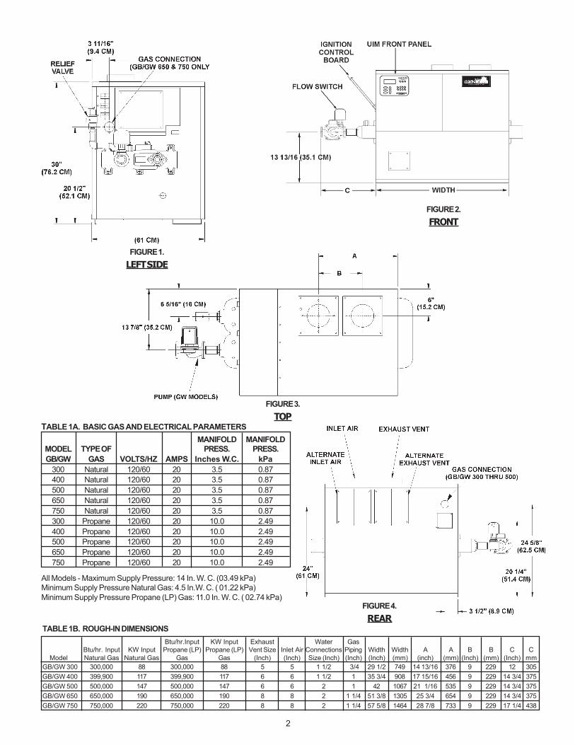
TABLE 1B. ROUGH-IN DIMENSIONSBtu/hr.Input KW Input Exhaust Water Gas
Btu/hr. Input KW Input Propane (LP) Propane (LP) Vent Size Inlet Air Connections Piping Width Width A A B B C C Model Natural Gas Natural Gas Gas Gas (Inch) (Inch) Size (Inch) (Inch) (Inch) (mm) (inch) (mm) (Inch) (mm) (Inch) mmGB/GW 300 300,000 88 300,000 88 5 5 1 1/2 3/4 29 1/2 749 14 13/16 376 9 229 12 305GB/GW 400 399,900 117 399,900 117 6 6 1 1/2 1 35 3/4 908 17 15/16 456 9 229 14 3/4 375GB/GW 500 500,000 147 500,000 147 6 6 2 1 42 1067 21 1/16 535 9 229 14 3/4 375GB/GW 650 650,000 190 650,000 190 8 8 2 1 1/4 51 3/8 1305 25 3/4 654 9 229 14 3/4 375GB/GW 750 750,000 220 750,000 220 8 8 2 1 1/4 57 5/8 1464 28 7/8 733 9 229 17 1/4 438
TABLE 1A. BASIC GAS AND ELECTRICAL PARAMETERSMANIFOLD MANIFOLD
MODEL TYPE OF PRESS. PRESS.GB/GW GAS VOLTS/HZ AMPS Inches W.C. kPa
300 Natural 120/60 20 3.5 0.87400 Natural 120/60 20 3.5 0.87500 Natural 120/60 20 3.5 0.87650 Natural 120/60 20 3.5 0.87750 Natural 120/60 20 3.5 0.87300 Propane 120/60 20 10.0 2.49400 Propane 120/60 20 10.0 2.49500 Propane 120/60 20 10.0 2.49650 Propane 120/60 20 10.0 2.49750 Propane 120/60 20 10.0 2.49
All Models - Maximum Supply Pressure: 14 In. W. C. (03.49 kPa)Minimum Supply Pressure Natural Gas: 4.5 In.W. C. ( 01.22 kPa)Minimum Supply Pressure Propane (LP) Gas: 11.0 In. W. C. ( 02.74 kPa)
FIGURE 1.LEFT SIDE
FIGURE 2.FRONT
FIGURE 3.TOP
FIGURE 4.REAR
3
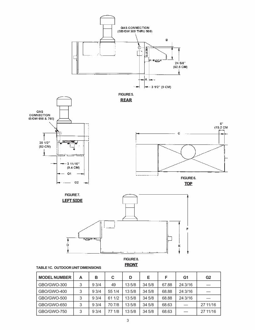
FIGURE 6.TOP
FIGURE 7.LEFT SIDE
FIGURE 8.FRONT
MODEL NUMBER A B C D E F G1 G2
GBO/GWO-300 3 9 3/4 49 13 5/8 34 5/8 67.88 24 3/16 —GBO/GWO-400 3 9 3/4 55 1/4 13 5/8 34 5/8 68.88 24 3/16 —GBO/GWO-500 3 9 3/4 61 1/2 13 5/8 34 5/8 68.88 24 3/16 —GBO/GWO-650 3 9 3/4 70 7/8 13 5/8 34 5/8 68.63 — 27 11/16GBO/GWO-750 3 9 3/4 77 1/8 13 5/8 34 5/8 68.63 — 27 11/16
TABLE 1C. OUTDOOR UNIT DIMENSIONS
FIGURE 5.REAR
4
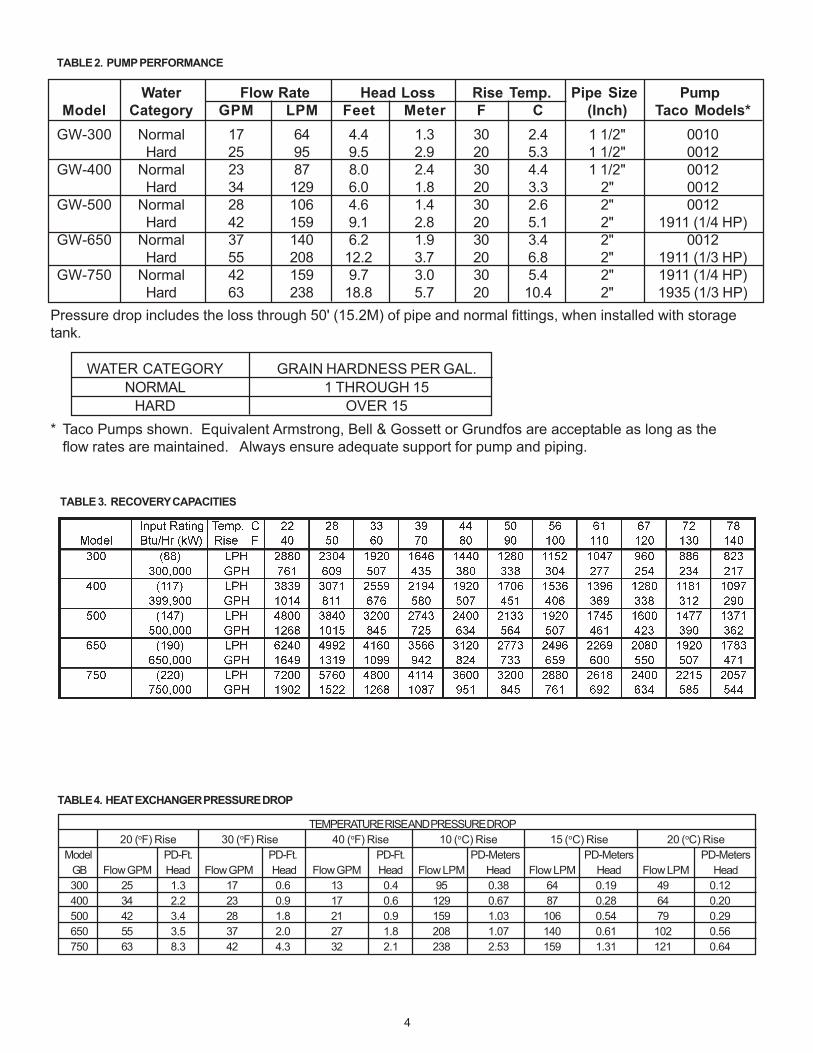
TABLE 2. PUMP PERFORMANCE
TABLE 3. RECOVERY CAPACITIES
TABLE 4. HEAT EXCHANGER PRESSURE DROP
Water Flow Rate Head Loss Rise Temp. Pipe Size PumpModel Category GPM LPM Feet Meter F C (Inch) Taco Models*
GW-300 Normal 17 64 4.4 1.3 30 2.4 1 1/2" 0010Hard 25 95 9.5 2.9 20 5.3 1 1/2" 0012
GW-400 Normal 23 87 8.0 2.4 30 4.4 1 1/2" 0012Hard 34 129 6.0 1.8 20 3.3 2" 0012
GW-500 Normal 28 106 4.6 1.4 30 2.6 2" 0012Hard 42 159 9.1 2.8 20 5.1 2" 1911 (1/4 HP)
GW-650 Normal 37 140 6.2 1.9 30 3.4 2" 0012Hard 55 208 12.2 3.7 20 6.8 2" 1911 (1/3 HP)
GW-750 Normal 42 159 9.7 3.0 30 5.4 2" 1911 (1/4 HP)Hard 63 238 18.8 5.7 20 10.4 2" 1935 (1/3 HP)
Pressure drop includes the loss through 50' (15.2M) of pipe and normal fittings, when installed with storagetank.
WATER CATEGORY GRAIN HARDNESS PER GAL.NORMAL 1 THROUGH 15
HARD OVER 15* Taco Pumps shown. Equivalent Armstrong, Bell & Gossett or Grundfos are acceptable as long as the
flow rates are maintained. Always ensure adequate support for pump and piping.
TEMPERATURE RISE AND PRESSURE DROP20 (oF) Rise 30 (oF) Rise 40 (oF) Rise 10 (oC) Rise 15 (oC) Rise 20 (oC) Rise
Model PD-Ft. PD-Ft. PD-Ft. PD-Meters PD-Meters PD-MetersGB Flow GPM Head Flow GPM Head Flow GPM Head Flow LPM Head Flow LPM Head Flow LPM Head300 25 1.3 17 0.6 13 0.4 95 0.38 64 0.19 49 0.12400 34 2.2 23 0.9 17 0.6 129 0.67 87 0.28 64 0.20500 42 3.4 28 1.8 21 0.9 159 1.03 106 0.54 79 0.29650 55 3.5 37 2.0 27 1.8 208 1.07 140 0.61 102 0.56750 63 8.3 42 4.3 32 2.1 238 2.53 159 1.31 121 0.64
5
FOREWORD CAUTION
TEXT PRINTED OR OUTLINED IN RED CONTAINSINFORMATION RELATIVE TO YOUR SAFETY. PLEASE READCOMPLETELY BEFORE USING APPLIANCE.
Detailed installation diagrams are in this manual. Thesediagrams will provide the installer with a reference of materialsneeded and a suggested method of piping. IT IS NECESSARYTHAT ALL WATER AND GAS PIPING, AND THE ELECTRICALWIRING BE INSTALLED AND CONNECTED AS SHOWN IN THEDIAGRAMS.
CHECK THE DIAGRAMS THOROUGHLY BEFORE STARTINGINSTALLATION TO AVOID POSSIBLE ERRORS AND TO MINIMIZETIME AND MATERIALS COST. SEE FIGURES 1 THROUGH 4AND TABLES 1A, 1B AND 1C.
This design complies with the current edition of ANSI Z21.13 -CSA 4.9 for Gas-Fired Low-Pressure Steam and Hot WaterBoilers.
MAKE SURE THE GAS ON WHICH THE BOILER WILL OPERATEIS THE SAME AS THAT SPECIFIED ON THE BOILER RATINGPLATE.
The boiler installation must conform to these instructions andthe requirements of the local authority having jurisdiction.
In the absence of local code requirements, the installation mustconform to the National Fuel Gas Code, ANSI Z223.1 or CAN/CSA-B149.1-00 (current edition).
These manuals can be purchased from the CanadianStandards Association, 8501 East Pleasant Valley Road,Cleveland, OH 44131.
REPLACEMENT PARTSReplacement parts may be ordered through A. O. Smith dealers,authorized servicers or distributors. Refer to the Yellow Pagesfor where to call or contact (in United States) the A. O. SmithWater Products Company, 500 Tennessee Waltz Parkway,Ashland City, TN 37015, 1-800-433-2545 or (in Canada) A. O.Smith Enterprises Ltd., 768 Erie Street, Stratford, Ontario, CanadaN5A 6T3, 800-265-8520. When ordering parts be sure to statethe quantity, part number and description of the item includingthe complete model and serial number as it appears on theproduct. Refer to the parts lists for more information.
For Technical Assistance call A. O. Smith Technical InformationCenter at 1-800-527-1953.
WARNINGTHE WATER MANIFOLD IS NOT DESIGNED TO SUPPORT THEWEIGHT OF THE WATER PIPING SYSTEM. AS ON ALL BOILERINSTALLATIONS, SPECIAL CARE MUST BE TAKEN TO ENSUREPROPER SUPPORT.
WARNINGUNDER NO CIRCUMSTANCES SHOULD THE EQUIPMENTROOM WHERE THE BOILER IS INSTALLED EVER BE UNDERNEGATIVE PRESSURE. PARTICULAR CARE MUST BE TAKENWHEN EXHAUST FANS, COMPRESSORS, AIR HANDLINGEQUIPMENT, ETC., MAY INTERFERE WITH THE COMBUSTIONAND VENTILATION AIR SUPPLIES OF THIS BOILER.
CAUTIONLabel all wires prior to disconnection when servicing controls.Wiring errors can cause improper and dangerous operation ofthe boiler.
"Verify proper operation after servicing."
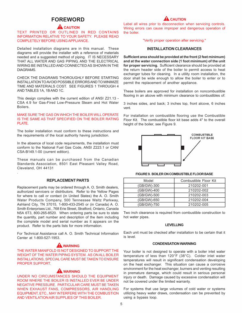
INSTALLATION CLEARANCES
Sufficient area should be provided at the front (2 feet minimum)and at the water connection side (1 foot minimum) of the unitfor proper servicing. Sufficient clearance should be provided atthe return header side of the boiler to permit access to heatexchanger tubes for cleaning. In a utility room installation, thedoor shall be wide enough to allow the boiler to enter or topermit the replacement of another appliance.
These boilers are approved for installation on noncombustibleflooring in an alcove with minimum clearance to combustibles of:
3 inches sides, and back; 3 inches top, front alcove, 6 inchesvent.
For installation on combustible flooring use the CombustibleFloor Kit. The combustible floor kit base adds 4" to the overallheight of the boiler, see Figure 9.
FIGURE 9. BOILER ON COMBUSTIBLE FLOOR BASE
Model Combustible Floor Kit(GB/GW)-300 210202-001(GB/GW)-400 210202-002(GB/GW)-500 210202-003(GB/GW)-650 210202-004(GB/GW)-750 210202-005
Two inch clearance is required from combustible construction tohot water pipes.
LEVELLING
Each unit must be checked after installation to be certain that itis level.
CONDENSATION WARNING
Your boiler is not designed to operate with a boiler inlet watertemperature of less than 120°F (38°C). Colder inlet watertemperatures will result in significant condensation developingon the heat exchanger. This situation can cause a corrosiveenvironment for the heat exchanger, burners and venting resultingin premature damage, which could result in serious personalinjury or death. Damage caused by excessive condensation willnot be covered under the limited warranty.
For systems that use large volumes of cold water or systemsutilizing heavy water draws, condensation can be prevented byusing a bypass loop.
6
FEATURESIMPORTANT
Only qualified personnel shall perform the initial firing of the heater.At this time the user should not hesitate to ask the start-uptechnician any questions regarding the operation andmaintenance of the unit.
Lighting and Operating instructions are included with this manual.By using these instructions, the user may be able to make minoroperational adjustments and save unnecessary service calls.However, the user should not attempt repairs, but should contacta service technician or gas supplier.
SAFETY RELIEF VALVESYour local code authority may have other specific relief valverequirements not covered below.
WARNINGTHE PURPOSE OF A SAFETY RELIEF VALVE IS TO AVOIDEXCESSIVE PRESSURE WHICH MAY CAUSE TANK EXPLOSION,SYSTEM OR BOILER DAMAGE.
TO AVOID WATER DAMAGE A DRAIN LINE MUST BECONNECTED TO A SAFETY RELIEF VALVE TO DIRECTDISCHARGE TO A SAFE LOCATION. A DRAIN LINE MUST NOTBE REDUCED FROM THE SIZE OF THE VALVE OUTLET AND ITMUST NOT CONTAIN ANY VALVES BETWEEN THE BOILER ANDTHE RELIEF VALVE OR THE RELIEF VALVE AND THE DRAINEXIT. IN ADDITION, THERE SHOULD NOT BE ANYRESTRICTIONS IN A DRAIN LINE NOR SHOULD IT BE ROUTEDTHROUGH AREAS WHERE FREEZING CONDITIONS MIGHTOCCUR. DO NOT THREAD OR CAP THE DRAIN LINE EXIT.RESTRICTING OR BLOCKING A DRAIN LINE WILL DEFEAT THEPURPOSE OF THE RELIEF VALVE AND MAY CREATE AN UNSAFECONDITION. INSTALL A DRAIN LINE WITH A DOWNWARDSLOPE SUCH THAT IT NATURALLY DRAINS ITSELF.
If any safety relief valve is replaced, the replacement valve mustcomply with the latest version of the ASME Boiler and PressureVessel Code, Section IV (HEATING BOILERS). Select a reliefvalve with a discharge rating NOT less than the boiler input, anda set pressure NOT exceeding the working pressure of anycomponent in the system.
The storage tank temperature and pressure relief valve mustcomply with the applicable construction provisions of the Standardfor Relief Valves for Hot Water Supply Systems, ANSI Z21.22 -CSA 4.4 (current edition). The valve must be of the automaticreset type and not embody a single-use type fusible plug, cartridgeor linkage.
FOR HOT WATER HEATING SYSTEMS, the boilers are shippedwith a 50 psi pressure relief valve. This relief valve is factoryinstalled in the water outlet header of the boiler, see Figure 1.
FOR HOT WATER SUPPLY SYSTEMS, the boilers are shippedwith a 125 psi pressure relief valve. This relief valve is factoryinstalled in the water outlet header of the boiler, see Figure 1.
This ASME-rated valve has a discharge capacity that exceeds themaximum boiler input rating and a pressure rating that does notexceed the maximum working pressure shown on the boilerrating plate.
In addition, a CSA design-certified and ASME-rated temperatureand pressure (T & P) relief valve must be installed on each andevery water storage tank in the hot water supply system.
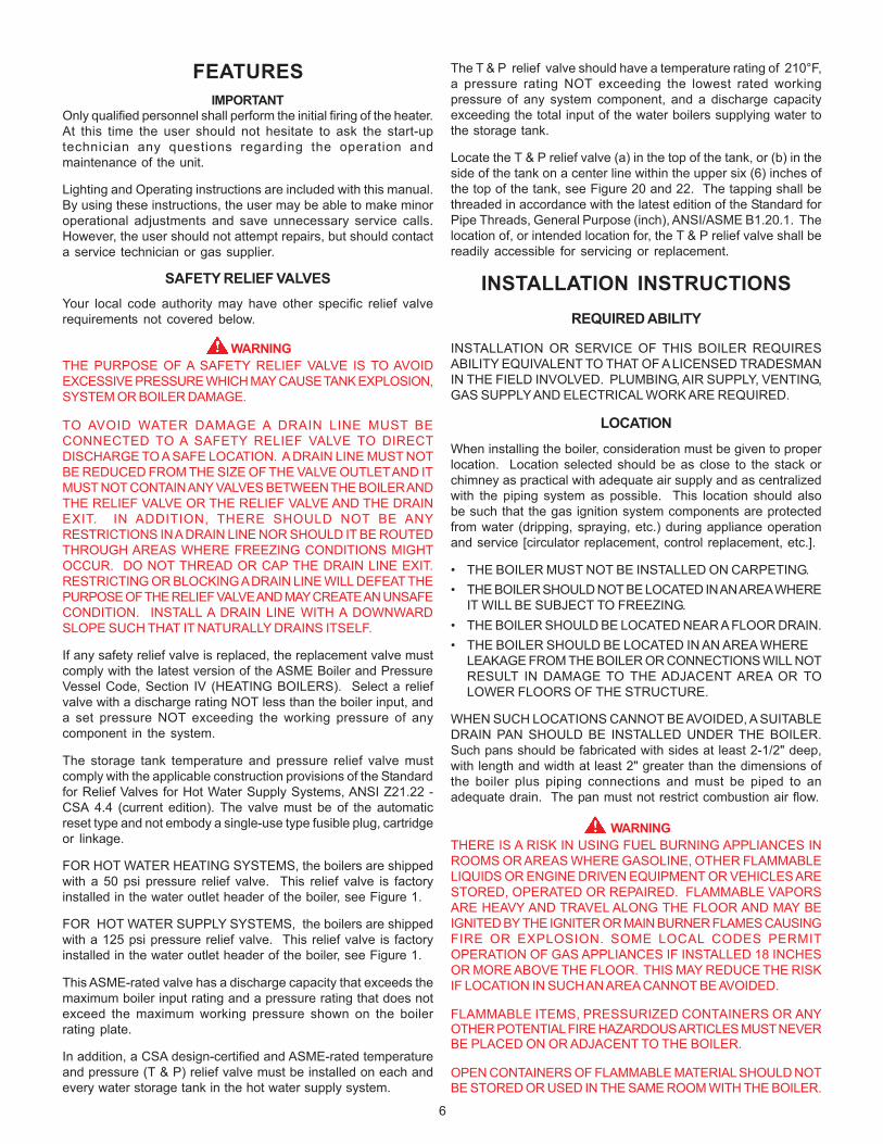
The T & P relief valve should have a temperature rating of 210°F,a pressure rating NOT exceeding the lowest rated workingpressure of any system component, and a discharge capacityexceeding the total input of the water boilers supplying water tothe storage tank.
Locate the T & P relief valve (a) in the top of the tank, or (b) in theside of the tank on a center line within the upper six (6) inches ofthe top of the tank, see Figure 20 and 22. The tapping shall bethreaded in accordance with the latest edition of the Standard forPipe Threads, General Purpose (inch), ANSI/ASME B1.20.1. Thelocation of, or intended location for, the T & P relief valve shall bereadily accessible for servicing or replacement.
INSTALLATION INSTRUCTIONSREQUIRED ABILITY
INSTALLATION OR SERVICE OF THIS BOILER REQUIRESABILITY EQUIVALENT TO THAT OF A LICENSED TRADESMANIN THE FIELD INVOLVED. PLUMBING, AIR SUPPLY, VENTING,GAS SUPPLY AND ELECTRICAL WORK ARE REQUIRED.
LOCATION
When installing the boiler, consideration must be given to properlocation. Location selected should be as close to the stack orchimney as practical with adequate air supply and as centralizedwith the piping system as possible. This location should alsobe such that the gas ignition system components are protectedfrom water (dripping, spraying, etc.) during appliance operationand service [circulator replacement, control replacement, etc.].
• THE BOILER MUST NOT BE INSTALLED ON CARPETING.• THE BOILER SHOULD NOT BE LOCATED IN AN AREA WHERE
IT WILL BE SUBJECT TO FREEZING.• THE BOILER SHOULD BE LOCATED NEAR A FLOOR DRAIN.• THE BOILER SHOULD BE LOCATED IN AN AREA WHERE
LEAKAGE FROM THE BOILER OR CONNECTIONS WILL NOTRESULT IN DAMAGE TO THE ADJACENT AREA OR TOLOWER FLOORS OF THE STRUCTURE.
WHEN SUCH LOCATIONS CANNOT BE AVOIDED, A SUITABLEDRAIN PAN SHOULD BE INSTALLED UNDER THE BOILER.Such pans should be fabricated with sides at least 2-1/2" deep,with length and width at least 2" greater than the dimensions ofthe boiler plus piping connections and must be piped to anadequate drain. The pan must not restrict combustion air flow.
WARNINGTHERE IS A RISK IN USING FUEL BURNING APPLIANCES INROOMS OR AREAS WHERE GASOLINE, OTHER FLAMMABLELIQUIDS OR ENGINE DRIVEN EQUIPMENT OR VEHICLES ARESTORED, OPERATED OR REPAIRED. FLAMMABLE VAPORSARE HEAVY AND TRAVEL ALONG THE FLOOR AND MAY BEIGNITED BY THE IGNITER OR MAIN BURNER FLAMES CAUSINGFIRE OR EXPLOSION. SOME LOCAL CODES PERMITOPERATION OF GAS APPLIANCES IF INSTALLED 18 INCHESOR MORE ABOVE THE FLOOR. THIS MAY REDUCE THE RISKIF LOCATION IN SUCH AN AREA CANNOT BE AVOIDED.
FLAMMABLE ITEMS, PRESSURIZED CONTAINERS OR ANYOTHER POTENTIAL FIRE HAZARDOUS ARTICLES MUST NEVERBE PLACED ON OR ADJACENT TO THE BOILER.
OPEN CONTAINERS OF FLAMMABLE MATERIAL SHOULD NOTBE STORED OR USED IN THE SAME ROOM WITH THE BOILER.
7
continuous operation). GB models require a field suppliedoperating control be installed in the system. Such as: loop stat,indoor/outdoor reset control, sequencing panel, or energymanagement system. These types of controls connect to thethermostat wires in the junction box on the boiler. Do not operatethis boiler using the internal high limits only, you must use anoperating stat as mentioned above.
CIRCULATING PUMP
The pump flow rate should not exceed the maximumrecommended flow rate, see Table 2.
FOR HOT WATER SUPPLY SYSTEMS (GW models), the circulatingpump is an integral part of the Boiler, see Figure 3. This pumphas been lubricated at the factory, and future lubrication shouldbe in accordance with the motor manufacturer's instructionsprovided as supplement to this manual.
FOR HOT WATER HEATING SYSTEMS (GB models), the circulatingpump is NOT provided and must be field-installed.
SAFETY FLOW SWITCH (Supplied)
The safety flow switch is a safety device which is installed at thewater outlet of the unit to prevent main burner operation in theevent of inadequate water flow through the boiler.
This switch is connected to the CCB, and its status is displayedon the "System Status" screen. An asterisk indicates switchclosure (water flowing).
LOW WATER CUTOFF (OPTIONAL)
If low water protection is required by the authorities havingjurisdiction, a low water cutoff switch should be installed next tothe boiler in the outlet water line as shown in Figure 23. To meetcode requirements the power connections for this switch can beconnected to the LWCO connections on the CCB, but theindependent contacts for feedback should not be. They shouldbe connected in series with the ECO. When connected in thismanner, the LWCO dipswitch on the CCB should be off. Thesystem will not recognize a low water fault condition as a LWCOfault. It will respond with an ECO fault. The switch should receiveperiodic (every six months) inspection to assure proper operation.A low water cutoff device of the float type should be flushed everysix months. If a LWCO is desired, but not required by code, it canbe connected to the LWCO connections on the CCB and thedipswitch should be turned to on. The system will then recognizea low water fault condition as LWCO fault.
DRAIN VALVE (Not Supplied)
Drain valves must be obtained and installed on each boiler andtank for draining purposes.
AIR REQUIREMENTS
WARNINGFOR SAFE OPERATION, AN AMPLE SUPPLY OF AIR MUST BEPROVIDED FOR PROPER COMBUSTION AND VENTILATION INACCORDANCE WITH THE NATIONAL FUEL GAS CODE, ANSIZ223.1 OR CAN/CSA-B149.1 (CURRENT EDITIONS) ORAPPLICABLE PROVISIONS OF THE LOCAL BUILDING CODES.AN INSUFFICIENT SUPPLY OF AIR MAY RESULT IN A YELLOW,LUMINOUS BURNER FLAME, CARBONING OR SOOTING OFTHE FINNED HEAT EXCHANGER, OR CREATE A RISK OFASPHYXIATION. DO NOT OBSTRUCT THE FLOW OFCOMBUSTION AND VENTILATION AIR.
If the boiler is installed above the level of heating system terminalunits, a low water cutoff device must be installed in the boileroutlet at the time of installation.
CHEMICAL VAPOR CORROSION
Heat exchanger corrosion and component failure can be causedby the heating and breakdown of airborne chemical vapors. Spraycan propellants, cleaning solvents, refrigerator and airconditioning refrigerants, swimming pool chemicals, calciumand sodium chloride, waxes, and process chemicals are typicalcompounds which are corrosive. These materials are corrosiveat very low concentration levels with little or no odor to reveal theirpresence.
Products of this sort should not be stored near the boiler. Also,air which is brought in contact with the water boiler should notcontain any of these chemicals. If necessary, uncontaminatedair should be obtained from remote or outside sources.
MANUAL RESET HIGH TEMPERATURE LIMIT CONTROL
This device prevents the water temperature from reaching 250°F.This device is located in the outlet temperature probe.
AUTOMATIC RESETHIGH TEMPERATURE LIMIT CONTROL
CAUTIONLIMIT CONTROLS ARE NOT TO BE USED AS A THERMOSTAT.
This device prevents the outlet water temperature from reachingthe setpoint. Its operation is based on the feedback from theoutlet temperature probe. If the temperature exceeds the setpoint,a fault is declared and the gas is shut off. The fault condition isautomatically cleared when the temperature drops below thehigh limit setpoint minus the high limit differential. The factorypreset values (and the default high limit values) are 210°F forGW models and 230°F for GB models. The user can adjustthese values between 90°F and 210°F for the GW models and90°F and 235°F for the GB models. The factory preset value (andthe default high limit differential value) for both models is 20°F.The user adjustable range is 1°F to 50°F.
TANK PROBE/INLET PROBE
FOR HOT WATER SUPPLY SYSTEMS (GW models), A tank probeis supplied with each hot water supply boiler. When a tank probeis connected to the system, the tank section on the UIMtemperature screen will display a temperature instead of dashes.
"Pigtails" of field-supplied wires should be spliced to "pigtails" oftank probe and to "pigtails" at the junction box. See Figure 21 forthe tank probe installation. Operating control of the system willbe transferred to the tank probe when "Tank Cont" is selected ondip switch #3 off "SW1" on the CCB.
In the absence of tank probe, the inlet probe can be used forboiler stage control. Staging control will be transferred to inletprobe when "Inlet" is selected on dip switch #3 on CCB. Makesure to set the boiler pump for continuous operation.
FOR HOT WATER HEATING SYSTEMS (GB models) Due to thevarious types of systems and operating conditions, no factoryoperating control is supplied with the GB models. If no probe isattached to the system, then the dip switch on the CCB shouldbe set to inlet control (and make sure that boiler pump is set for
8
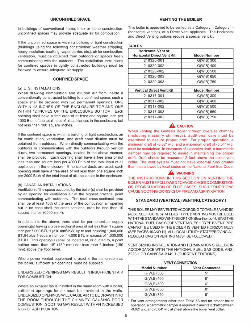
VENTING THE BOILER!This boiler is approved to be vented as a Category I, Category III(horizontal venting), or a Direct Vent appliance. The Horizontaland Direct Venting options require a special vent kit.
TABLE 5.Horizontal Vent or
Horizontal Direct Vent Kit Model Number210320-001 G(W,B) 300210320-002 G(W,B) 400210320-002 G(W,B) 500210320-003 G(W,B) 650210320-003 G(W,B) 750
Vertical Direct Vent Kit Model Number210317-001 G(W,B) 300210317-002 G(W,B) 400210317-002 G(W,B) 500210317-003 G(W,B) 650210317-003 G(W,B) 750
CAUTIONWhen venting the Genesis Boiler through oversize chimney(including masonry chimneys), additional care must beexercised to assure proper draft. For proper operation, aminimum draft of -0.02" w.c. and a maximum draft of -0.04" w.c.must be maintained. In instances of excessive draft, a barometricdamper may be required to assist in maintaining the properdraft. Draft should be measured 2 feet above the boiler ventcollar. The vent system must not have external runs greaterthan that allowed by local codes or the National Fuel Gas Code.
WARNINGTHE INSTRUCTIONS IN THIS SECTION ON VENTING THEBOILER MUST BE FOLLOWED TO AVOID CHOKED COMBUSTIONOR RECIRCULATION OF FLUE GASES. SUCH CONDITIONSCAUSE SOOTING OR RISKS OF FIRE AND ASPHYXIATION.
STANDARD (VERTICAL) VENTING, CATEGORY I
THIS BOILER MAY BE VENTED ACCORDING TO TABLE 5A AND 5C(ALSO SEE FIGURE 6). AT LEAST TYPE B VENTING MUST BE USEDWITH THE STANDARD VENTING OPTION (thru-the-roof) USING THENATIONAL FUEL GAS CODE VENT TABLES.* TYPE B VENT PIPECANNOT BE USED IF THE BOILER IS VENTED HORIZONTALLY(SEE PAGES 10 AND 11). ALL LOCAL UTILITY, STATE/PROVINCIAL,REGULATIONS ON VENTING MUST BE FOLLOWED.
VENT SIZING, INSTALLATION AND TERMINATION SHALL BE INACCORDANCE WITH THE NATIONAL FUEL GAS CODE, ANSIZ223.1 OR CAN/CSA-B149.1 (CURRENT EDITIONS).
VENT CONNECTIONModel Number Vent Connector
G(W,B) 300 5"G(W,B) 400 6"G(W,B) 500 6"G(W,B) 650 8"G(W,B) 750 8"
* For vent arrangements other than Table 5A and for proper boileroperation, a barometric damper is required to maintain draft between-0.02" w.c. and -0.04" w.c at 2 feet above the boiler vent collar.
UNCONFINED SPACE
In buildings of conventional frame, brick or stone construction,unconfined spaces may provide adequate air for combustion.
If the unconfined space is within a building of tight construction(buildings using the following construction: weather stripping,heavy insulation, caulking, vapor barrier, etc.), air for combustion,ventilation, must be obtained from outdoors or spaces freelycommunicating with the outdoors. The installation instructionsfor confined spaces in tightly constructed buildings must befollowed to ensure adequate air supply.
CONFINED SPACE
(a) U. S. INSTALLATIONSWhen drawing combustion and dilution air from inside aconventionally constructed building to a confined space, such aspace shall be provided with two permanent openings, ONEWITHIN 12 INCHES OF THE ENCLOSURE TOP AND ONEWITHIN 12 INCHES OF THE ENCLOSURE BOTTOM. Eachopening shall have a free area of at least one square inch per1000 Btuh of the total input of all appliances in the enclosure, butnot less than 100 square inches.
If the confined space is within a building of tight construction, airfor combustion, ventilation, and draft hood dilution must beobtained from outdoors. When directly communicating with theoutdoors or communicating with the outdoors through verticalducts, two permanent openings, located in the above manner,shall be provided. Each opening shall have a free area of notless than one square inch per 4000 Btuh of the total input of allappliances in the enclosure. If horizontal ducts are used, eachopening shall have a free area of not less than one square inchper 2000 Btuh of the total input of all appliances in the enclosure.
(b) CANADIAN INSTALLATIONSVentilation of the space occupied by the boiler(s) shall be providedby an opening for ventilation air at the highest practical pointcommunicating with outdoors. The total cross-sectional areashall be at least 10% of the area of the combustion air openingbut in no case shall the cross-sectional area be less than 10square inches (6500 mm2).
In addition to the above, there shall be permanent air supplyopening(s) having a cross-sectional area of not less than 1 squareinch per 7,000 BTUH (310 mm2/KW) up to and including 1,000,000BTUH plus 1 square inch per 14,000 BTU in excess of 1,000,000BTUH. This opening(s) shall be located at, or ducted to, a pointneither more than 18" (450 mm) nor less than 6 inches (150mm) above the floor level.
Where power vented equipment is used in the same room asthe boiler, sufficient air openings must be supplied.
UNDERSIZED OPENINGS MAY RESULT IN INSUFFICIENT AIRFOR COMBUSTION.
Where an exhaust fan is installed in the same room with a boiler,sufficient openings for air must be provided in the walls.UNDERSIZED OPENINGS WILL CAUSE AIR TO BE DRAWN INTOTHE ROOM THROUGH THE CHIMNEY, CAUSING POORCOMBUSTION. SOOTING MAY RESULT WITH AN INCREASEDRISK OF ASPHYXIATION.
9
All boiler venting systems shall be installed in accordance with theNational Fuel Gas Code, ANSI Z223.1 or CAN/CSA-B149.1 (currentedition), or applicable provisions of the local building codes.
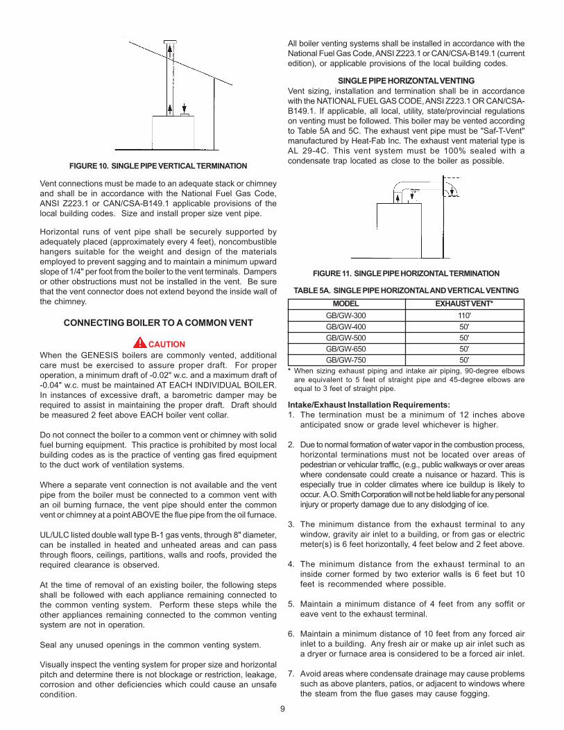
SINGLE PIPE HORIZONTAL VENTINGVent sizing, installation and termination shall be in accordancewith the NATIONAL FUEL GAS CODE, ANSI Z223.1 OR CAN/CSA-B149.1. If applicable, all local, utility, state/provincial regulationson venting must be followed. This boiler may be vented accordingto Table 5A and 5C. The exhaust vent pipe must be "Saf-T-Vent"manufactured by Heat-Fab Inc. The exhaust vent material type isAL 29-4C. This vent system must be 100% sealed with acondensate trap located as close to the boiler as possible.
FIGURE 11. SINGLE PIPE HORIZONTAL TERMINATION
TABLE 5A. SINGLE PIPE HORIZONTAL AND VERTICAL VENTINGMODEL EXHAUST VENT*
GB/GW-300 110'GB/GW-400 50'GB/GW-500 50'GB/GW-650 50'GB/GW-750 50'
* When sizing exhaust piping and intake air piping, 90-degree elbowsare equivalent to 5 feet of straight pipe and 45-degree elbows areequal to 3 feet of straight pipe.
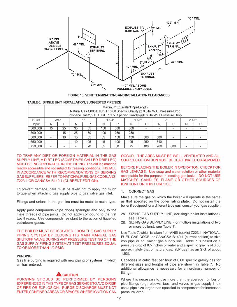
Intake/Exhaust Installation Requirements:1. The termination must be a minimum of 12 inches above
anticipated snow or grade level whichever is higher.
2. Due to normal formation of water vapor in the combustion process,horizontal terminations must not be located over areas ofpedestrian or vehicular traffic, (e.g., public walkways or over areaswhere condensate could create a nuisance or hazard. This isespecially true in colder climates where ice buildup is likely tooccur. A.O. Smith Corporation will not be held liable for any personalinjury or property damage due to any dislodging of ice.
3. The minimum distance from the exhaust terminal to anywindow, gravity air inlet to a building, or from gas or electricmeter(s) is 6 feet horizontally, 4 feet below and 2 feet above.
4. The minimum distance from the exhaust terminal to aninside corner formed by two exterior walls is 6 feet but 10feet is recommended where possible.
5. Maintain a minimum distance of 4 feet from any soffit oreave vent to the exhaust terminal.
6. Maintain a minimum distance of 10 feet from any forced airinlet to a building. Any fresh air or make up air inlet such asa dryer or furnace area is considered to be a forced air inlet.
7. Avoid areas where condensate drainage may cause problemssuch as above planters, patios, or adjacent to windows wherethe steam from the flue gases may cause fogging.
FIGURE 10. SINGLE PIPE VERTICAL TERMINATION
Vent connections must be made to an adequate stack or chimneyand shall be in accordance with the National Fuel Gas Code,ANSI Z223.1 or CAN/CSA-B149.1 applicable provisions of thelocal building codes. Size and install proper size vent pipe.
Horizontal runs of vent pipe shall be securely supported byadequately placed (approximately every 4 feet), noncombustiblehangers suitable for the weight and design of the materialsemployed to prevent sagging and to maintain a minimum upwardslope of 1/4" per foot from the boiler to the vent terminals. Dampersor other obstructions must not be installed in the vent. Be surethat the vent connector does not extend beyond the inside wall ofthe chimney.
CONNECTING BOILER TO A COMMON VENT
CAUTIONWhen the GENESIS boilers are commonly vented, additionalcare must be exercised to assure proper draft. For properoperation, a minimum draft of -0.02" w.c. and a maximum draft of-0.04" w.c. must be maintained AT EACH INDIVIDUAL BOILER.In instances of excessive draft, a barometric damper may berequired to assist in maintaining the proper draft. Draft shouldbe measured 2 feet above EACH boiler vent collar.
Do not connect the boiler to a common vent or chimney with solidfuel burning equipment. This practice is prohibited by most localbuilding codes as is the practice of venting gas fired equipmentto the duct work of ventilation systems.
Where a separate vent connection is not available and the ventpipe from the boiler must be connected to a common vent withan oil burning furnace, the vent pipe should enter the commonvent or chimney at a point ABOVE the flue pipe from the oil furnace.
UL/ULC listed double wall type B-1 gas vents, through 8" diameter,can be installed in heated and unheated areas and can passthrough floors, ceilings, partitions, walls and roofs, provided therequired clearance is observed.
At the time of removal of an existing boiler, the following stepsshall be followed with each appliance remaining connected tothe common venting system. Perform these steps while theother appliances remaining connected to the common ventingsystem are not in operation.
Seal any unused openings in the common venting system.
Visually inspect the venting system for proper size and horizontalpitch and determine there is not blockage or restriction, leakage,corrosion and other deficiencies which could cause an unsafecondition.
10
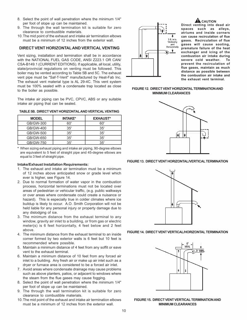
8. Select the point of wall penetration where the minimum 1/4"per foot of slope up can be maintained.
9. The through the wall termination kit is suitable for zeroclearance to combustible materials.
10.The mid point of the exhaust and intake air termination elbowsmust be a minimum of 12 inches from the exterior wall.
DIRECT VENT HORIZONTAL AND VERTICAL VENTING
Vent sizing, installation and termination shall be in accordancewith the NATIONAL FUEL GAS CODE, ANSI Z223.1 OR CAN/CSA-B149.1 (CURRENT EDITIONS). If applicable, all local, utility,state/provincial regulations on venting must be followed. Thisboiler may be vented according to Table 5B and 5C. The exhaustvent pipe must be "Saf-T-Vent" manufactured by Heat-Fab Inc.The exhaust vent material type is AL 29-4C. This vent systemmust be 100% sealed with a condensate trap located as closeto the boiler as possible.
The intake air piping can be PVC, CPVC, ABS or any suitableintake air piping that can be sealed.
TABLE 5B. DIRECT VENT HORIZONTAL AND VERTICAL VENTING
MODEL INTAKE* EXHAUST*GB/GW-300 60' 60'GB/GW-400 35' 35'GB/GW-500 35' 35'GB/GW-650 35' 35'GB/GW-750 35' 35'
* When sizing exhaust piping and intake air piping, 90-degree elbowsare equivalent to 5 feet of straight pipe and 45-degree elbows areequal to 3 feet of straight pipe.
Intake/Exhaust Installation Requirements:1. The exhaust and intake air termination must be a minimum
of 12 inches above anticipated snow or grade level whichever is higher, see Figure 14.
2. Due to normal formation of water vapor in the combustionprocess, horizontal terminations must not be located overareas of pedestrian or vehicular traffic, (e.g. public walkwaysor over areas where condensate could create a nuisance orhazard). This is especially true in colder climates where icebuildup is likely to occur. A.O. Smith Corporation will not beheld liable for any personal injury or property damage due toany dislodging of ice.
3. The minimum distance from the exhaust terminal to anywindow, gravity air inlet to a building, or from gas or electricmeter(s) is 6 feet horizontally, 4 feet below and 2 feetabove.
4. The minimum distance from the exhaust terminal to an insidecorner formed by two exterior walls is 6 feet but 10 feet isrecommended where possible.
5. Maintain a minimum distance of 4 feet from any soffit or eavevent to the exhaust terminal.
6. Maintain a minimum distance of 10 feet from any forced airinlet to a building. Any fresh air or make up air inlet such as adryer or furnace area is considered to be a forced air inlet.
7. Avoid areas where condensate drainage may cause problemssuch as above planters, patios, or adjacent to windows wherethe steam from the flue gases may cause fogging.
8. Select the point of wall penetration where the minimum 1/4"per foot of slope up can be maintained.
9. The through the wall termination kit is suitable for zeroclearance to combustible materials.
10.The mid point of the exhaust and intake air termination elbowsmust be a minimum of 12 inches from the exterior wall.
FIGURE 12. DIRECT VENT HORIZONTAL TERMINATION ANDMINIMUM CLEARANCES
FIGURE 13. DIRECT VENT HORIZONTAL/VERTICAL TERMINATION
FIGURE 14. DIRECT VENT VERTICAL/HORIZONTAL TERMINATION
FIGURE 15. DIRECT VENT VERTICAL TERMINATION ANDMINIMUM CLEARANCES
CAUTIONDirect venting into dead airspaces such as alleys,atriums and inside cornerscan cause recirculation of fluegases. Recirculation of fluegases will cause sooting,premature failure of the heatexchanger and icing of thecombustion air intake duringsevere cold weather. Toprevent the recirculation offlue gases, maintain as muchdistance as possible betweenthe combustion air intake andthe exhaust vent terminal.
11
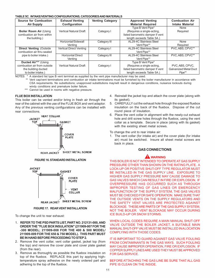
FLUE BOX INSTALLATIONThis boiler can be vented and/or bring in fresh air through therear of the cabinet with the use of the FLUE BOX and vent adaptor.Any of the previous venting configurations can be installed withrear connections.
FIGURE 16. STANDARD INSTALLATION
FIGURE 17. REAR VENT INSTALLATION
To change the unit to rear exhaust:
1. REFER TO THE PSD PARTS LIST, PART NO. 212131-000, ANDORDER THE "FLUE BOX INSULATION" (211909-007 FOR THE-300 MODEL; 211909-008 FOR THE 400 & 500 MODEL/211909-009 FOR THE 650 & 750 MODEL). THIS PART MUSTBE IN HAND BEFORE PROCEEDING TO STEP 2.
2. Remove the vent collar, vent collar gasket, jacket top (fromthe top) and remove the cover plate and cover plate gasket(from the rear).
3. Remove as thoroughly as possible the fluebox insulation ontop of the fluebox. REPLACE this part by applying high-temperature spray adhesive on the newly ordered part andadhering to the top of the fluebox.
4. Reinstall the jacket top and attach the cover plate (along withits gasket).
5. CAREFULLY cut the exhaust hole through the exposed flueboxinsulation on the back of the fluebox. Dispose of the cutround piece of insulation.
6. Place the vent collar in alignment with the newly-cut exhausthole and drill screw holes through the fluebox, using the ventcollar as a template. Secure in place (along with its gasket)with the existing sheet metal screws.
To change the unit to rear intake air:1. The vent collar (for intake air) and the cover plate (for intake
air) must be switched. Insure all sheet metal screws areback in place.
GAS CONNECTIONS
WARNINGTHIS BOILER IS NOT INTENDED TO OPERATE AT GAS SUPPLYPRESSURE OTHER THAN SHOWN ON THE RATING PLATE. ALOCK-UP OR POSITIVE SHUT-OFF TYPE REGULATOR MUSTBE INSTALLED IN THE GAS SUPPLY LINE. EXPOSURE TOHIGHER GAS SUPPLY PRESSURE MAY CAUSE DAMAGE TOGAS VALVES WHICH CAN RESULT IN FIRE OR EXPLOSION. IFOVERPRESSURE HAS OCCURRED SUCH AS THROUGHIMPROPER TESTING OF GAS LINES OR EMERGENCYMALFUNCTION OF THE SUPPLY SYSTEM, THE GAS VALVESMUST BE CHECKED FOR SAFE OPERATION. MAKE SURE THATTHE OUTSIDE VENTS ON THE SUPPLY REGULATORS ANDTHE SAFETY VENT VALVES ARE PROTECTED AGAINSTBLOCKAGE. THESE ARE PARTS OF THE GAS SUPPLY SYSTEM,NOT THE BOILER. VENT BLOCKAGE MAY OCCUR DURINGICE BUILD-UP OR SNOW STORMS.
WHEN LOCAL CODES REQUIRE A MAIN MANUAL SHUT-OFFVALVE OUTSIDE THE BOILER JACKET, A SUITABLE MAINMANUAL SHUT-OFF VALVE MUST BE INSTALLED IN A LOCATIONCOMPLYING WITH THOSE CODES.
IT IS IMPORTANT TO GUARD AGAINST GAS VALVE FOULINGFROM CONTAMINANTS IN THE GAS WAYS. SUCH FOULINGMAY CAUSE IMPROPER OPERATION, FIRE OR EXPLOSION. IFCOPPER SUPPLY LINES ARE USED THEY MUST BE APPROVEDFOR GAS SERVICE.
BEFORE ATTACHING THE GAS LINE BE SURE THAT ALL GASPIPE IS CLEAN ON THE INSIDE.
TABLE 5C. INTAKE/VENTING CONFIGURATIONS, CATEGORIES AND MATERIALSSource for Combustion Exhaust Venting Venting Category Approved Venting Combustion Air
Air Supply Configuration Material Required Intake MaterialType B Vent Pipe* None
Boiler Room Air (Using Vertical Natural Draft Category I (Requires a single-acting, Requiredcombustion air from within listed barometric damper if vent
the building.) length exceeds Table 5A.)Horizontal/Sidewall Category III AL29-4C Stainless Steel None
Venting Vent Pipe** RequiredDirect Venting (Outside Vertical Direct Venting Category I AL29-4C Stainless Steel PVC, ABS, CPVC**combustion air thru sealed Vent Pipe**
pipe to boiler intake.) Horizontal Direct Category III AL29-4C Stainless Steel PVC, ABS, CPVC**Venting Vent Pipe**
Ducted Air*** (Using Type B Vent Pipe*combustion air from outside Vertical Natural Draft Category I (Requires a single-acting, PVC, ABS, CPVC,
the building ducted listed barometric damper if vent Galvanized Metal Ductto boiler intake.) length exceeds Table 5A.) Pipe**
NOTES: * A standard list type B vent terminal as supplied by the vent pipe manufacturer may be used.** Vent cap/vent terminations and combustion air intake terminations must be furnished by the boiler manufacturer in accordance with
CSA requirements. No substitutions; unapproved substitutions may/will result in dangerous conditions, nuisance lockouts duringwindy conditions and premature boiler failure.
*** Cannot be used in rooms with negative pressure.
12
TO TRAP ANY DIRT OR FOREIGN MATERIAL IN THE GASSUPPLY LINE, A DIRT LEG (SOMETIMES CALLED DRIP LEG)MUST BE INCORPORATED IN THE PIPING. The dirt leg must bereadily accessible and not subject to freezing conditions. INSTALLIN ACCORDANCE WITH RECOMMENDATIONS OF SERVINGGAS SUPPLIERS. REFER TO NATIONAL FUEL GAS CODE, ANSIZ223.1 OR CAN/CSA-B149.1 (CURRENT EDITION).
To prevent damage, care must be taken not to apply too muchtorque when attaching gas supply pipe to gas valve gas inlet.
Fittings and unions in the gas line must be metal to metal type.
Apply joint compounds (pipe dope) sparingly and only to themale threads of pipe joints. Do not apply compound to the firsttwo threads. Use compounds resistant to the action of liquefiedpetroleum gases.
THE BOILER MUST BE ISOLATED FROM THE GAS SUPPLYPIPING SYSTEM BY CLOSING ITS MAIN MANUAL GASSHUTOFF VALVE DURING ANY PRESSURE TESTING OF THEGAS SUPPLY PIPING SYSTEM AT TEST PRESSURES EQUALTO OR MORE THAN 1/2 PSIG.
PURGINGGas line purging is required with new piping or systems in whichair has entered.
CAUTIONPURGING SHOULD BE PERFORMED BY PERSONSEXPERIENCED IN THIS TYPE OF GAS SERVICE TO AVOID RISKOF FIRE OR EXPLOSION. PURGE DISCHARGE MUST NOTENTER CONFINED AREAS OR SPACES WHERE IGNITION CAN
OCCUR. THE AREA MUST BE WELL VENTILATED AND ALLSOURCES OF IGNITION MUST BE DEACTIVATED OR REMOVED.
BEFORE PLACING THE BOILER IN OPERATION, CHECK FORGAS LEAKAGE. Use soap and water solution or other materialacceptable for the purpose in locating gas leaks. DO NOT USEMATCHES, CANDLES, FLAME OR OTHER SOURCES OFIGNITION FOR THIS PURPOSE.
1. CORRECT GASMake sure the gas on which the boiler will operate is the sameas that specified on the boiler rating plate. Do not install theboiler if equipped for a different type gas, consult your gas supplier.
2A. SIZING GAS SUPPLY LINE, (for single boiler installations),see Table 6.
2B. SIZING GAS SUPPLY LINE, (for multiple installations of twoor more boilers), see Table 7.
Use Table 7, which is taken from ANSI booklet Z223.1, NATIONALFUEL GAS CODE, or CAN/CSA-B149.1 (current edition) to sizeiron pipe or equivalent gas supply line. Table 7 is based on apressure drop of 0.5 inches of water and a specific gravity of 0.60approximately that of natural gas. (LP gas has an S.G. of about1.53).
Capacities in cubic feet per hour of 0.60 specific gravity gas fordifferent sizes and lengths of pipe are shown in Table 7. Noadditional allowance is necessary for an ordinary number offittings.
Where it is necessary to use more than the average number ofpipe fittings (e.g., elbows, tees, and valves in gas supply line),use a pipe size larger than specified to compensate for increasedpressure drop.
FIGURE 18. VENT TERMINATIONS AND INSTALLATION CLEARANCES
TABLE 6. SINGLE UNIT INSTALLATION, SUGGESTED PIPE SIZEMaximum Equivalent Pipe Length
Natural Gas 1,000 BTU/FT3 0.60 Specific Gravity @ 0.5 In. W.C. Pressure DropPropane Gas 2,500 BTU/FT3 1.53 Specific Gravity @ 0.60 In.W.C. Pressure Drop
BTUH 3/4" 1" 1 1/4" 1 1/2" 2" 2 1/2"Input N P N P N P N P N P N P
300,000 15 25 35 85 150 380 360 - - - - -399,900 - 15 25 60 100 260 250 - - - - -500,000 - 10 15 35 65 150 130 360 500 - - -650,000 - - 10 25 45 100 95 250 340 - - -750,000 - - - 20 35 80 75 180 260 600 - -

13
TABLE 8. MULTIPLIER TABLESpecific SpecificGravity Multiplier Gravity Multiplier0.55 1.04 1.00 0.78
0.60 (natural) 1.00 1.10 0.740.65 0.96 1.20 0.710.70 0.93 1.30 0.680.75 0.90 1.40 0.660.80 0.87 1.50 (Propane) 0.630.85 0.84 1.60 0.610.90 0.82 1.70 0.59
Applications of the gravity factor converts the figures given inTable 7 to capacities with another gas of different specific gravity.Such application is accomplished by multiplying the capacitiesgiven in Table 7 by the multipliers shown in Table 8.
HIGH ALTITUDE INSTALLATIONS
WARNINGINSTALLATIONS ABOVE 5,000 FEET REQUIRE REPLACEMENTOF THE BURNER ORIFICES IN ACCORDANCE WITH THENATIONAL FUEL GAS CODE (ANSI/NFPA 54). FAILURE TOREPLACE THE ORIFICES WILL RESULT IN IMPROPER ANDINEFFICIENT OPERATION OF THE APPLIANCE, PRODUCINGCARBON MONOXIDE GAS IN EXCESS OF SAFE LIMITS, WHICHCOULD RESULT IN SERIOUS PERSONAL INJURY OR DEATH.
These Genesis boilers are equipped with prejet orifices whichare self-regulating. This makes it unnecessary to replace theseprejet orifices for high altitude installations (up to 5,000 feet only.Consult the factory for higher altitudes). These prejet orifices willautomatically compensate for higher elevations and adjust theappliance's input rate accordingly, see Table 9.
Some utility companies derate their gas for altitude. You shouldcontact your gas supplier for any specific changes which may berequired in your area. Call the local gas utility to verify BTU contentof the gas supplied.
Ratings specified by manufacturers for most boilers apply forelevations up to 2000 feet (600 m). For elevations above 2000feet (600 m) ratings must be reduced by a rate of 4% for each1000 feet (300 m) above sea level.
Example: A Genesis boiler is rated at 750,000 Btu/hr. input at sealevel. At an altitude of 5,000 (1500m), the prejet orifices willdecrease the input rate by 20% (= 4% x 5) to a new rating of600,000 Btu/hr. (= 80% x 750,000 Btu/hr.) The input reduction isachieved by the prejet orifices through self-regulation.
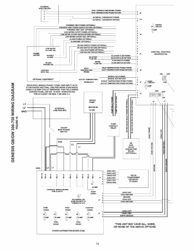
WIRING CONNECTIONS
ALL ELECTRICAL WORK MUST BE INSTALLED INACCORDANCE WITH THE CURRENT EDITIONS OF THENATIONAL ELECTRICAL CODE NFPA 70/CANADIANELECTRICAL CODE, CSA 22.1 AND MUST CONFORM TO LOCALREGULATIONS.
AN ELECTRICAL GROUND IS REQUIRED TO REDUCE RISKOF ELECTRIC SHOCK OR POSSIBLE ELECTROCUTION. Makethe ground connection to the wire provided in the electrical supplyjunction box on the boiler.
Grounding and all wiring connected to this boiler must conformto the local code authority having jurisdiction or, in the absence ofsuch requirements, with the National Electrical Code, ANSI/NFPA70 or CSA-C22.1 current edition.
IF ANY OF THE ORIGINAL WIRE, AS SUPPLIED WITH THEAPPLIANCE, MUST BE REPLACED, IT MUST BE REPLACEDWITH TYPE 105°C WIRE OR ITS EQUIVALENT.
The Genesis Hot Water Supply Boiler must be connected to asingle phase dedicated and isolated line source that is:
120 volts, 60 Hertz, and 20 Amps.The feedback contacts for a system controller (e.g. HoneywellAquastat) that is attached to the thermostat input, must operateon the provided 24 VAC power.
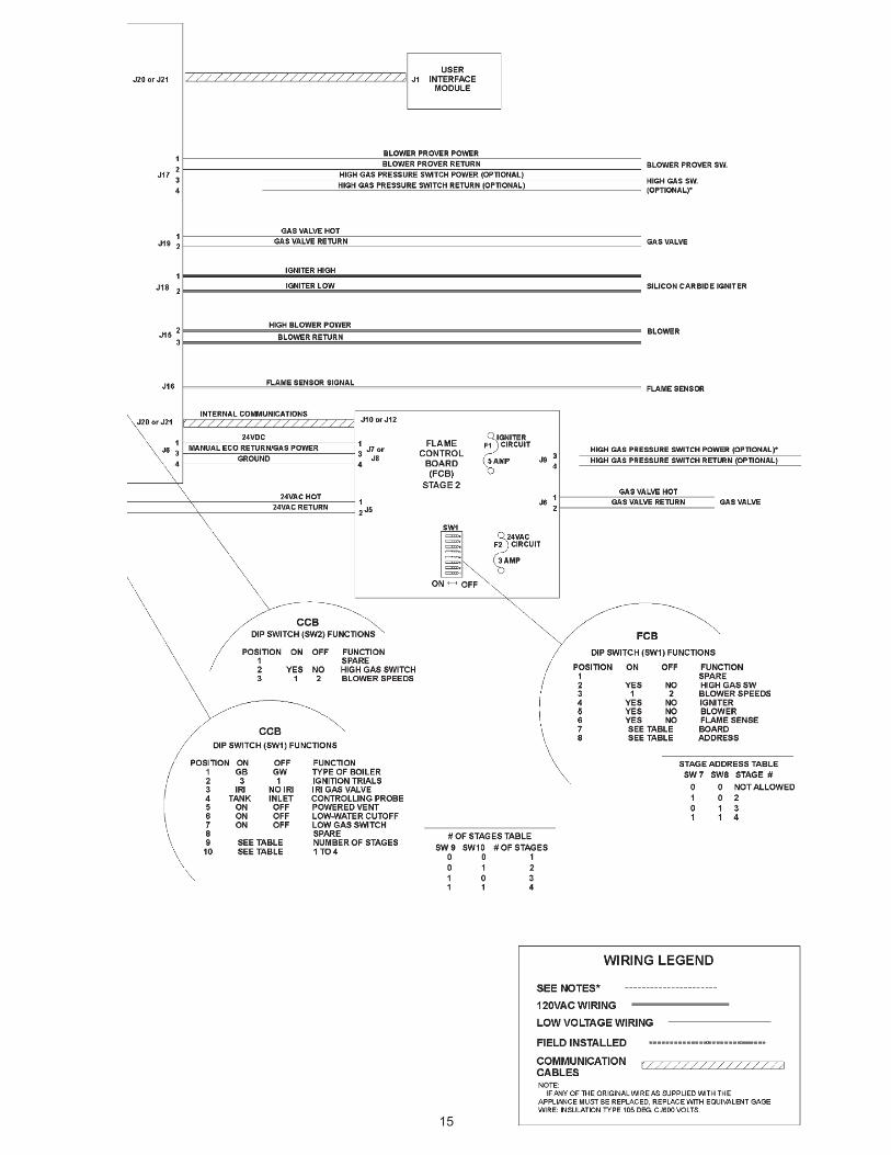
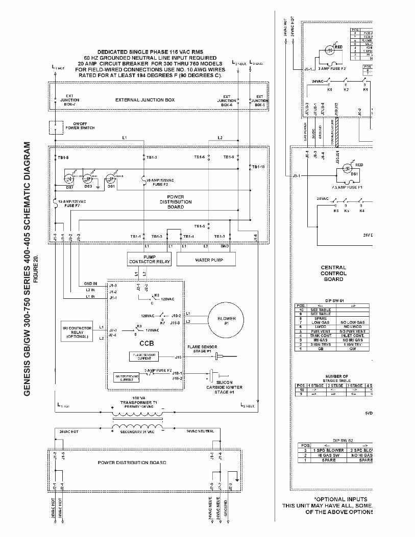
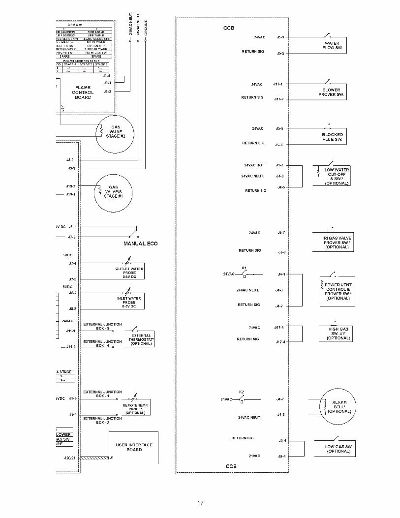
Refer to the Connection Diagram and to the SchematicDiagram.
TABLE 7. SUGGESTED PIPE SIZE FOR MULTIPLE GAS APPLIANCES
Nominal Maximum Capacity of Pipe in Cubic Feet of Gas per Hour for Gas PressuresIron Pipe of 14 in. W.C. (0.5 psi) or Less and a Pressure Drop of 0.5 in W.C. based on a 0.60 Specific Gravity Gas Size in Length of Pipe (Feet)Inches 10 20 30 40 50 60 70 80 90 100 125 150 175 200
1 680 465 375 320 285 260 240 220 205 195 175 160 145 1351 1/4 1,400 950 770 660 580 530 490 460 430 400 360 325 300 2801 1/2 2,100 1,460 1,180 990 900 810 750 690 650 620 550 500 460 430
2 3,950 2,750 2,200 1,900 1,680 1,520 1,400 1,300 1,220 1,150 1,020 950 850 8002 1/2 6,300 4,350 3,520 3,000 2,650 2,400 2,250 2,050 1,950 1,850 1,650 1,500 1,370 1,280
3 11,000 7,700 6,250 5,300 4,750 4,300 3,900 3,700 3,450 3,250 2,950 2,650 2,450 2,2804 23,000 15,800 12,800 10,900 9,700 8,800 8,100 7,500 7,200 6,700 6,000 5,500 5,000 4,600
TABLE 9: ORIFICE SIZE FOR NATURAL AND PROPANE (LP) GASES (U.S. AND CANADIAN INSTALLATIONS)(Drill size unless otherwise indicated.)
Model Rating Input BTUH Number of Burners Natural (3X) Propane (3X)GB/GW 300 300,000 6 0.091" 0.048"GB/GW 400 399,900 8 0.091" 0.048"GB/GW 500 500,000 10 0.091" 0.048"GB/GW 650 650,000 13 0.091" 0.048"GB/GW 750 750,000 15 0.091" 0.048"
14
GEN
ESIS
GB
/GW
300
-750
WIR
ING
DIA
GR
AM
FIG
URE
19.
15
16
GEN
ESIS
GB
/GW
300
-750
SER
IES
400-
405
SCH
EMAT
IC D
IAG
RA
MFI
GUR
E 20
.
17
18
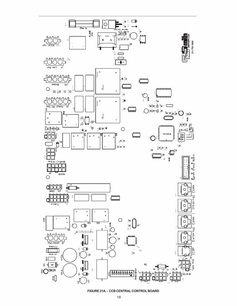
FIGURE 21A. - CCB CENTRAL CONTROL BOARD
19
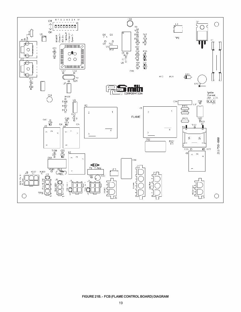
FIGURE 21B. - FCB (FLAME CONTROL BOARD) DIAGRAM

20
FIGURE 21C. - PDB (POWER DISTRIBUTION BOARD) DIAGRAM
21
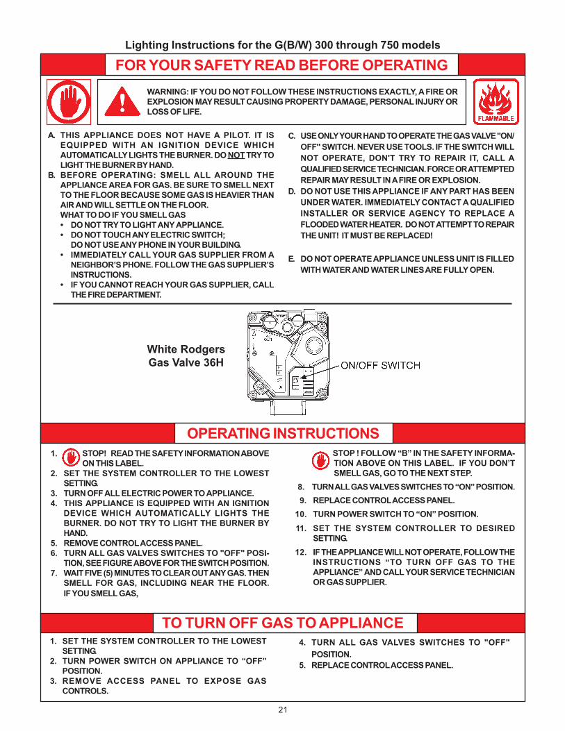
Lighting Instructions for the G(B/W) 300 through 750 models
WARNING: IF YOU DO NOT FOLLOW THESE INSTRUCTIONS EXACTLY, A FIRE OREXPLOSION MAY RESULT CAUSING PROPERTY DAMAGE, PERSONAL INJURY ORLOSS OF LIFE.
FOR YOUR SAFETY READ BEFORE OPERATING
A. THIS APPLIANCE DOES NOT HAVE A PILOT. IT ISEQUIPPED WITH AN IGNITION DEVICE WHICHAUTOMATICALLY LIGHTS THE BURNER. DO NOT TRY TOLIGHT THE BURNER BY HAND.
B. BEFORE OPERATING: SMELL ALL AROUND THEAPPLIANCE AREA FOR GAS. BE SURE TO SMELL NEXTTO THE FLOOR BECAUSE SOME GAS IS HEAVIER THANAIR AND WILL SETTLE ON THE FLOOR.WHAT TO DO IF YOU SMELL GAS• DO NOT TRY TO LIGHT ANY APPLIANCE.• DO NOT TOUCH ANY ELECTRIC SWITCH;
DO NOT USE ANY PHONE IN YOUR BUILDING.• IMMEDIATELY CALL YOUR GAS SUPPLIER FROM A
NEIGHBOR’S PHONE. FOLLOW THE GAS SUPPLIER’SINSTRUCTIONS.
• IF YOU CANNOT REACH YOUR GAS SUPPLIER, CALLTHE FIRE DEPARTMENT.
C. USE ONLY YOUR HAND TO OPERATE THE GAS VALVE "ON/OFF" SWITCH. NEVER USE TOOLS. IF THE SWITCH WILLNOT OPERATE, DON'T TRY TO REPAIR IT, CALL AQUALIFIED SERVICE TECHNICIAN. FORCE OR ATTEMPTEDREPAIR MAY RESULT IN A FIRE OR EXPLOSION.
D. DO NOT USE THIS APPLIANCE IF ANY PART HAS BEENUNDER WATER. IMMEDIATELY CONTACT A QUALIFIEDINSTALLER OR SERVICE AGENCY TO REPLACE AFLOODED WATER HEATER. DO NOT ATTEMPT TO REPAIRTHE UNIT! IT MUST BE REPLACED!
E. DO NOT OPERATE APPLIANCE UNLESS UNIT IS FILLEDWITH WATER AND WATER LINES ARE FULLY OPEN.
1. STOP! READ THE SAFETY INFORMATION ABOVEON THIS LABEL.
2. SET THE SYSTEM CONTROLLER TO THE LOWESTSETTING.
3. TURN OFF ALL ELECTRIC POWER TO APPLIANCE.4. THIS APPLIANCE IS EQUIPPED WITH AN IGNITION
DEVICE WHICH AUTOMATICALLY LIGHTS THEBURNER. DO NOT TRY TO LIGHT THE BURNER BYHAND.
5. REMOVE CONTROL ACCESS PANEL.6. TURN ALL GAS VALVES SWITCHES TO "OFF" POSI-
TION, SEE FIGURE ABOVE FOR THE SWITCH POSITION.7. WAIT FIVE (5) MINUTES TO CLEAR OUT ANY GAS. THEN
SMELL FOR GAS, INCLUDING NEAR THE FLOOR.IF YOU SMELL GAS,
1. SET THE SYSTEM CONTROLLER TO THE LOWESTSETTING.
2. TURN POWER SWITCH ON APPLIANCE TO “OFF”POSITION.
3. REMOVE ACCESS PANEL TO EXPOSE GASCONTROLS.
STOP ! FOLLOW “B” IN THE SAFETY INFORMA-TION ABOVE ON THIS LABEL. IF YOU DON’TSMELL GAS, GO TO THE NEXT STEP.
8. TURN ALL GAS VALVES SWITCHES TO “ON” POSITION.9. REPLACE CONTROL ACCESS PANEL.
10. TURN POWER SWITCH TO “ON” POSITION.11. SET THE SYSTEM CONTROLLER TO DESIRED
SETTING.12. IF THE APPLIANCE WILL NOT OPERATE, FOLLOW THE
INSTRUCTIONS “TO TURN OFF GAS TO THEAPPLIANCE” AND CALL YOUR SERVICE TECHNICIANOR GAS SUPPLIER.
4. TURN ALL GAS VALVES SWITCHES TO "OFF"POSITION.
5. REPLACE CONTROL ACCESS PANEL.
OPERATING INSTRUCTIONS
TO TURN OFF GAS TO APPLIANCE
White RodgersGas Valve 36H
22
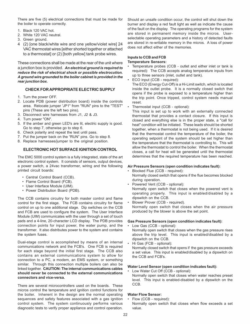
There are five (5) electrical connections that must be made forthe boiler to operate correctly.
1. Black 120 VAC hot.2. White 120 VAC neutral.3. Green ground.4 (2) [one black/white wire and one yellow/violet wire] 24
VAC thermostat wires [either shorted together or attachedto a thermostat] or (2) [both yellow] tank probe wires.
These connections shall be made at the rear of the unit wherea junction box is provided. An electrical ground is required toreduce the risk of electrical shock or possible electrocution.A ground wire grounded to the boiler cabinet is provided in therear junction box.
CHECK FOR APPROPRIATE ELECTRIC SUPPLY
1. Turn the power OFF.2. Locate PDB (power distribution board) inside the controls
area. Relocate jumper 'JP1" from "RUN" pins to the "TEST"pins (These are the left two pins).
3. Disconnect wire harnesses from J1, J2 & J3.4. Turn power "ON".5. If the amber and green LED's are lit, electric supply is good.
Go to step 7, otherwise go to step 6.6. Check polarity and repeat the test until pass.7. Put the jumper back on the “RUN” pins. Go to step 8.8. Replace harnesses/jumper to the original position.
ELECTRONIC HOT SURFACE IGNITION CONTROL
The EMC 5000 control system is a fully integrated, state of the artelectronic control system. It consists of sensors, output devices,a power switch, a 24vac transformer, wiring and the followingprinted circuit boards:
• Central Control Board (CCB).• Flame Control Board (FCB).• User Interface Module (UIM).• Power Distribution Board (PDB).
The CCB contains circuitry for both master control and flamecontrol for the first stage. The FCB contains circuitry for flamecontrol on up to one additional stage. Dip switches on the CCBand FCB are used to configure the system. The User InterfaceModule (UIM) communicates with the user through a set of touchpads and a 4-line, 20-character LCD display. The PDB providesconnection points for input power, the water pump, and thetransformer. It also distributes power to the system and containsthe system fuses.
Dual-stage control is accomplished by means of an internalcommunications network and the FCB's. One FCB is requiredfor each stage beyond the initial first stage. The CCB alsocontains an external communications system to allow forconnection to a PC, a modem, an EMS system, or somethingsimilar. Through this connection multiple boilers can also belinked together. CAUTION: The internal communications cablesshould never be connected to the external communicationsconnectors and vice-versa.
There are several microcontrollers used on the boards. Thesemicros control the temperature and ignition control functions forthe boiler. Inherent in the design are the normal operatingsequences and safety features associated with a gas ignitioncontrol system. The system continuously performs variousdiagnostic tests to verify proper appliance and control operation.
Should an unsafe condition occur, the control will shut down theburner and display a red fault light as well as indicate the causeof the fault on the display. The operating programs for the systemare stored in permanent memory inside the micros. User-selectable operating parameters and a history of detected faultsare stored in re-writable memory in the micros. A loss of powerdoes not affect either of the memories.
Inputs to CCB and FCBTemperature Sensors:• Temperature probes (CCB - outlet and either inlet or tank is
required): The CCB accepts analog temperature inputs fromup to three sensors (inlet, outlet and tank).
• ECO input (CCB - required):The ECO (Energy Cut-Off) is a Hi-Limit switch, which is locatedinside the outlet probe. It is a normally closed switch thatopens if the probe is exposed to a temperature higher thanthe trip point. Once tripped, control system needs manualreset.
• Thermostat input (CCB - optional):This input is set up to work with an externally connectedthermostat that provides a contact closure. If this input isclosed and everything else is in the proper state, a "call forheat" condition will be initiated. These leads should be shortedtogether, when a thermostat is not being used. If it is desiredthat the thermostat control the temperature of the boiler, theoperating setpoint of the system should be set higher thanthe temperature that the thermostat is controlling to. This willallow the thermostat to control the boiler. When the thermostatcloses, a call for heat will be generated until the thermostatdetermines that the required temperature has been reached.
Air Pressure Sensors (open condition indicates fault):• Blocked Flue (CCB - required):
Normally closed switch that opens if the flue becomes blockedduring operation.
• Powered Vent (CCB - optional):Normally open switch that closes when the powered vent isoperating properly. This input is enabled/disabled by adipswitch on the CCB.
• Blower Prover (CCB - required).Normally open switch that closes when the air pressureproduced by the blower is above the set point.
Gas Pressure Sensors (open condition indicates fault):• Low Gas (CCB - optional):
Normally open switch that closes when the gas pressure risesabove the trip level. This input is enabled/disabled by adipswitch on the CCB.
• Hi Gas (FCB - optional):Normally closed switch that opens if the gas pressure exceedsa set value. This input is enabled/disabled by a dipswitch onthe CCB and FCB's.
Water Level Sensor (open condition indicates fault):• Low Water Cut Off (CCB - optional):
Normally open switch that closes when water reaches presetlevel. This input is enabled-disabled by a dipswitch on theCCB.
Water Flow Sensor:• Flow (CCB - required):
Normally open switch that closes when flow exceeds a setvalue.
23
IRI Gas Valve Sensor:• IRI Gas Valve (CCB - optional):
Normally open switch that closes when the IRI Gas Valve isoperating correctly. This input is enabled/disabled by adipswitch on the CCB.
• Flame Sensor:Flame (CCB - required).Returns a signal to the microprocessor if flame is detected inthe burner. If the probe is missing or shorted, the flame willnot be detected. This input is enabled/disabled by a dipswitchon the FCB.
Outputs from CCB and FCB's:Relay Contact Output:• IRI Gas Valve (CCB - 120 vac - optional):
Provides electrical power to operate an IRI Gas Valve Device.• Alarm (CCB - 24vac - optional):
Provides electrical power to operate an external alarm. Thiscan be an audio device (i.e. Sonalert), a visual device (lamp),or any other device that will operate with the voltage and currentlevel provided.
• Pump (CCB - 120vac - required on systems that do not havean external pump):Provides electrical power to directly operate a pump or thecoil of an externally connected contactor.
• Powered Vent (CCB - 24 vac - optional):Provides electrical power to operate a powered vent.• Blower (CCB / FCB - 120vac - required).Single speed blowers utilize the high blower output only. Dipswitches on the FCB's enable/disable the use of blowers onstages 2, 3 and 4.
• Igniter (FCB - 120vac - required).Provides power to operate the HSI igniters. Dip switches onthe FCB's enables/disables the use of HSI igniters on stages2, 3 and 4.
• Gas Valve (FCB - 24vac - required):
Provides power to activate the gas valve. The gas valve cannotbe activated when the ECO contacts are openDirect Connection Output:
• Low Water Cut Off (CCB - 24vac - optional)Directly connected to the 24 vac line to provide power to operatean external LW/CO device.
CCB/FCB Indicator Lamps & FusesA green LED is mounted on the PDB to indicate when line voltageis applied. (The CCB/FCB/PDB also contain a yellow, green, redLED, and a test/run jumper, that are used during installation toverify proper power connections.) A red LED on the CCB is usedto indicate when the 24vac input fuse has blown. The FCB's alsohave fuses on their 24vac power line. (Recommendedreplacement fuses are: Littlefuse p/n 29707.5 for the 7.5 ampCCB fuse, and Littlefuse p/n 297003 for the 3 amp FCB fuses.)Repeated failure of a fuse is an indication of failure in somepart of the system.
Yellow LED's are located near the micros on the CCB and FCB's.These LED's are "heartbeat indicators" and blink approximatelytwice per second to indicate that the micros are running. (Theblink rate of the LED next to the micro that controls the siliconNitride igniter will change when the igniter is being powered andwhen a fault is detected with the operation of that igniter.)
CCB/FCB Jumpers:The CCB has two jumpers and the FCB has one. JP1 on theCCB is used to terminate the external communications line. It isnormally left off and installed when the external cable is verylong. JP2 on the CCB and JP1 on the FCB, are for factory useonly.
IgnitersThe EMC 5000 system operates with Silicon Carbide Igniter.
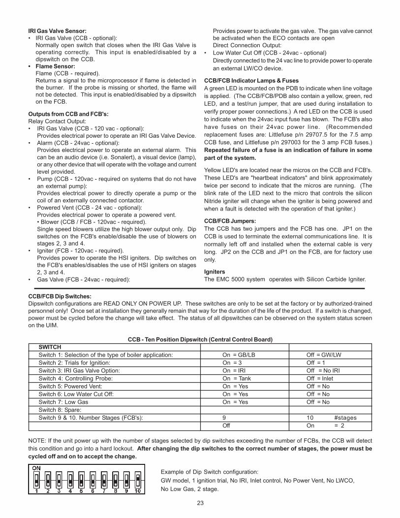
CCB/FCB Dip Switches:Dipswitch configurations are READ ONLY ON POWER UP. These switches are only to be set at the factory or by authorized-trainedpersonnel only! Once set at installation they generally remain that way for the duration of the life of the product. If a switch is changed,power must be cycled before the change will take effect. The status of all dipswitches can be observed on the system status screenon the UIM.
CCB - Ten Position Dipswitch (Central Control Board)SWITCHSwitch 1: Selection of the type of boiler application: On = GB/LB Off = GW/LWSwitch 2: Trials for Ignition: On = 3 Off = 1Switch 3: IRI Gas Valve Option: On = IRI Off = No IRISwitch 4: Controlling Probe: On = Tank Off = InletSwitch 5: Powered Vent: On = Yes Off = NoSwitch 6: Low Water Cut Off: On = Yes Off = NoSwitch 7: Low Gas On = Yes Off = NoSwitch 8: Spare:Switch 9 & 10. Number Stages (FCB's): 9 10 #stages
Off On = 2
NOTE: If the unit power up with the number of stages selected by dip switches exceeding the number of FCBs, the CCB will detectthis condition and go into a hard lockout. After changing the dip switches to the correct number of stages, the power must becycled off and on to accept the change.
Example of Dip Switch configuration:GW model, 1 ignition trial, No IRI, Inlet control, No Power Vent, No LWCO,No Low Gas, 2 stage.
24
Appliance Operating Sequence
NOTE: The following sequence is based on a two-stage system.
1. The EMC 5000 controller has four modes of operation:Initialization, Standby, Running, and Service. The internalCCB and FCB micros control these modes through asequence of steps (or States) which are further describedin the "UIM Operating Procedures" section.
2. When power is applied to the system, it enters theinitialization mode and the following automatic functionsare performed:• A. O. Smith opening screen is displayed.• The system goes through a calibration indicated by the
green running LED blinking and then staying on; nextthe red service LED and yellow standby LEDs come on,next the stage 1 service and runnings LEDs blink ONand OFF followed by stage 2, stage 3, stage 4 and thenback to stage 1, 2, 3, 4 LEDs.
• Stored values are recalled from memory.• Configuration dipswitches are read.• Pending faults are recalled• Micros on all boards start running (indicated by a flashing
Yellow LED near each micro)• Input sensors are read• Communications between micros and boards is
established• FCB's are configurated with the number of ignition trials
to run.3. After initialization is complete (approximately 10 seconds)
the system turns the green LED off and goes to the standbymode (yellow "Standby" LED on), unless a previously storedfault has been recalled, which will send the system into theservice model (red "Service" LED on). In standby modethe display shows the temperature screen and in fault mode
the current error screen is displayed.4. The system then compares the temperature read from the
controlling probe (inlet or tank) to the setpoint temperature.If the temperature is less than the operating setpoint minusthe differential temperature and the thermostat input isclosed then a call for heat is established and the systemshifts to the run mode (green "Running" LED turns on).
5. The heating sequence begins by applying power to thepump and, if selected, the powered vent and the IRI gasvalve.
6. After a few seconds the Blower is turned on to perform acold purge of the chamber.
7. The stage 1 igniter is turned on.8. After the Silcon Carbide igniter has reached a minimum of
2.8 amps, a current transducer relay is activated and closescontacts for the safety gas valve circuit. This allows the gasvalve power circuit to become energized.
9. After 1.5 seconds the system checks the status of the flamesensor. If flame is detected the system leaves the gasvalve "ON". Note: If the "Ignition Tries" dipswitch is set for 3tries the system will not declare an error until it tries theignition sequence three times. If it is set to 1 try then thesystem will declare an error anytime a fault is detected.
10. The system now activates the other FCB stages dependingupon a control algorithm scheme that is described below.
11. After 5 seconds the system turns on the gas valve forstage 2.
12. Carryover flame from stage 1 ignites stage 2’s burners.13. The system is now in the heating mode with both stages
on and will remain in this mode until the call for heat issatisfied or a fault occurs.
NOTE: In standby and running modes the system constantlymonitors the signals and the internal operation for faults. Anydetected fault will halt the heating sequence and shift the systemto the service mode, where the detected fault will be displayed.
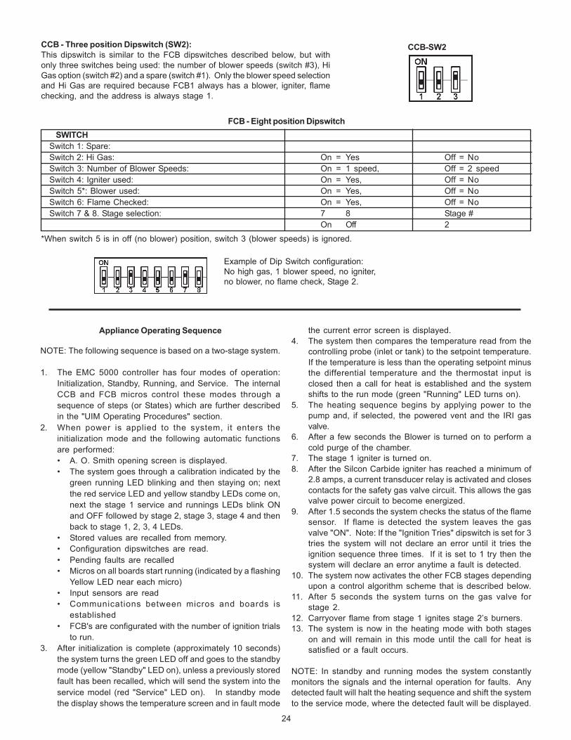
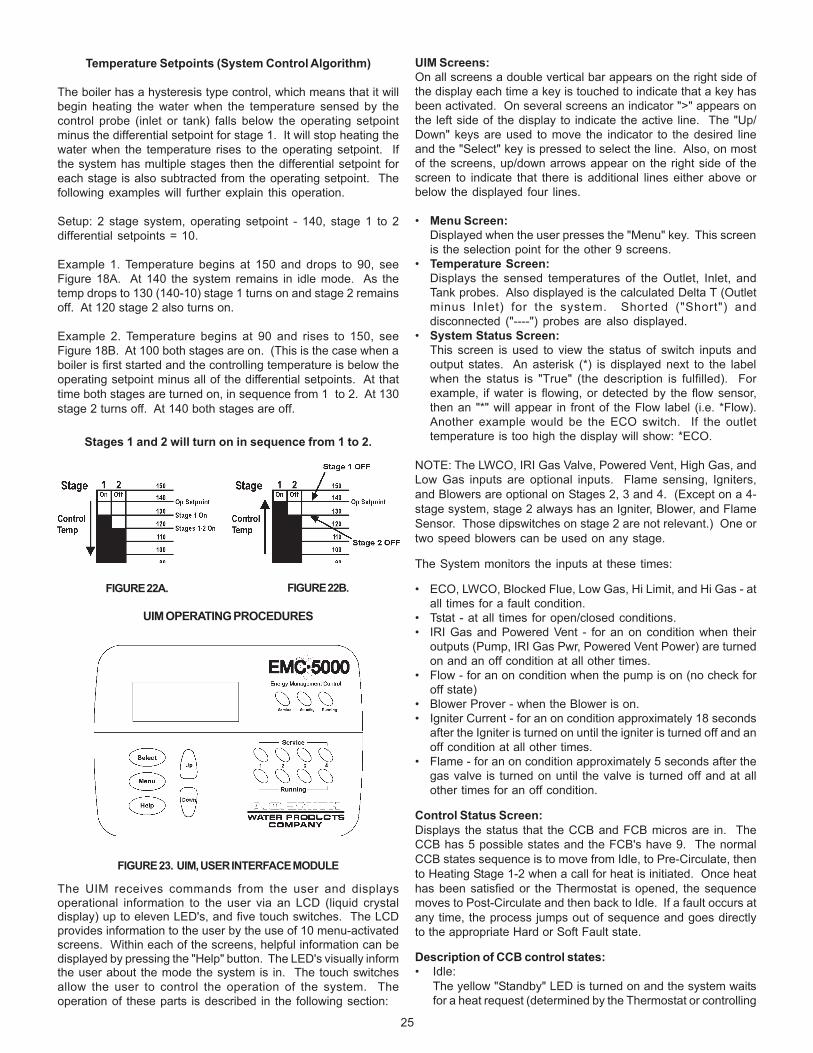
CCB - Three position Dipswitch (SW2):This dipswitch is similar to the FCB dipswitches described below, but withonly three switches being used: the number of blower speeds (switch #3), HiGas option (switch #2) and a spare (switch #1). Only the blower speed selectionand Hi Gas are required because FCB1 always has a blower, igniter, flamechecking, and the address is always stage 1.
FCB - Eight position DipswitchSWITCH
Switch 1: Spare:Switch 2: Hi Gas: On = Yes Off = NoSwitch 3: Number of Blower Speeds: On = 1 speed, Off = 2 speedSwitch 4: Igniter used: On = Yes, Off = NoSwitch 5*: Blower used: On = Yes, Off = NoSwitch 6: Flame Checked: On = Yes, Off = NoSwitch 7 & 8. Stage selection: 7 8 Stage #
On Off 2
*When switch 5 is in off (no blower) position, switch 3 (blower speeds) is ignored.
Example of Dip Switch configuration:No high gas, 1 blower speed, no igniter,no blower, no flame check, Stage 2.
CCB-SW2
25
UIM Screens:On all screens a double vertical bar appears on the right side ofthe display each time a key is touched to indicate that a key hasbeen activated. On several screens an indicator ">" appears onthe left side of the display to indicate the active line. The "Up/Down" keys are used to move the indicator to the desired lineand the "Select" key is pressed to select the line. Also, on mostof the screens, up/down arrows appear on the right side of thescreen to indicate that there is additional lines either above orbelow the displayed four lines.
• Menu Screen:Displayed when the user presses the "Menu" key. This screenis the selection point for the other 9 screens.
• Temperature Screen:Displays the sensed temperatures of the Outlet, Inlet, andTank probes. Also displayed is the calculated Delta T (Outletminus Inlet) for the system. Shorted ("Short") anddisconnected ("----") probes are also displayed.
• System Status Screen:This screen is used to view the status of switch inputs andoutput states. An asterisk (*) is displayed next to the labelwhen the status is "True" (the description is fulfilled). Forexample, if water is flowing, or detected by the flow sensor,then an "*" will appear in front of the Flow label (i.e. *Flow).Another example would be the ECO switch. If the outlettemperature is too high the display will show: *ECO.
NOTE: The LWCO, IRI Gas Valve, Powered Vent, High Gas, andLow Gas inputs are optional inputs. Flame sensing, Igniters,and Blowers are optional on Stages 2, 3 and 4. (Except on a 4-stage system, stage 2 always has an Igniter, Blower, and FlameSensor. Those dipswitches on stage 2 are not relevant.) One ortwo speed blowers can be used on any stage.
The System monitors the inputs at these times:
• ECO, LWCO, Blocked Flue, Low Gas, Hi Limit, and Hi Gas - atall times for a fault condition.
• Tstat - at all times for open/closed conditions.• IRI Gas and Powered Vent - for an on condition when their
outputs (Pump, IRI Gas Pwr, Powered Vent Power) are turnedon and an off condition at all other times.
• Flow - for an on condition when the pump is on (no check foroff state)
• Blower Prover - when the Blower is on.• Igniter Current - for an on condition approximately 18 seconds
after the Igniter is turned on until the igniter is turned off and anoff condition at all other times.
• Flame - for an on condition approximately 5 seconds after thegas valve is turned on until the valve is turned off and at allother times for an off condition.
Control Status Screen:Displays the status that the CCB and FCB micros are in. TheCCB has 5 possible states and the FCB's have 9. The normalCCB states sequence is to move from Idle, to Pre-Circulate, thento Heating Stage 1-2 when a call for heat is initiated. Once heathas been satisfied or the Thermostat is opened, the sequencemoves to Post-Circulate and then back to Idle. If a fault occurs atany time, the process jumps out of sequence and goes directlyto the appropriate Hard or Soft Fault state.
Description of CCB control states:• Idle:
The yellow "Standby" LED is turned on and the system waitsfor a heat request (determined by the Thermostat or controlling
Temperature Setpoints (System Control Algorithm)
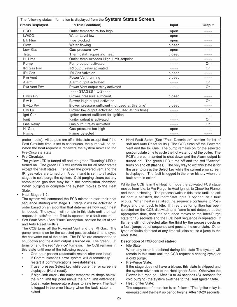
The boiler has a hysteresis type control, which means that it willbegin heating the water when the temperature sensed by thecontrol probe (inlet or tank) falls below the operating setpointminus the differential setpoint for stage 1. It will stop heating thewater when the temperature rises to the operating setpoint. Ifthe system has multiple stages then the differential setpoint foreach stage is also subtracted from the operating setpoint. Thefollowing examples will further explain this operation.
Setup: 2 stage system, operating setpoint - 140, stage 1 to 2differential setpoints = 10.
Example 1. Temperature begins at 150 and drops to 90, seeFigure 18A. At 140 the system remains in idle mode. As thetemp drops to 130 (140-10) stage 1 turns on and stage 2 remainsoff. At 120 stage 2 also turns on.
Example 2. Temperature begins at 90 and rises to 150, seeFigure 18B. At 100 both stages are on. (This is the case when aboiler is first started and the controlling temperature is below theoperating setpoint minus all of the differential setpoints. At thattime both stages are turned on, in sequence from 1 to 2. At 130stage 2 turns off. At 140 both stages are off.
Stages 1 and 2 will turn on in sequence from 1 to 2.
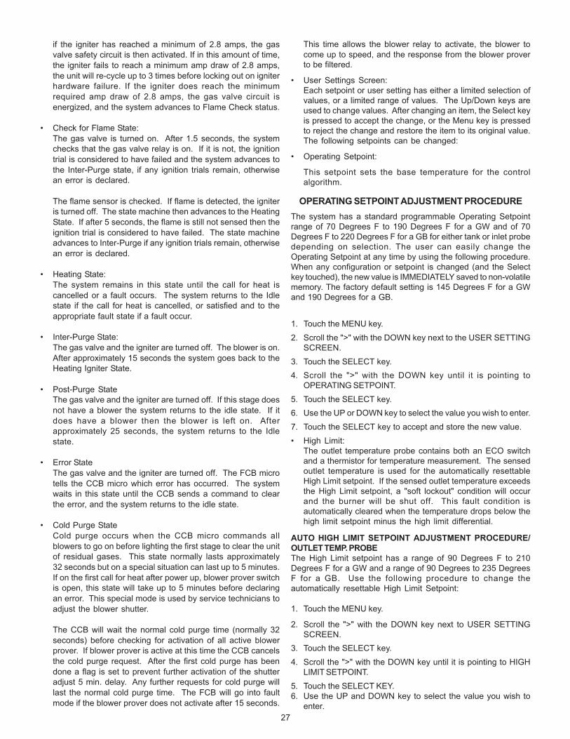
UIM OPERATING PROCEDURES
FIGURE 23. UIM, USER INTERFACE MODULE
The UIM receives commands from the user and displaysoperational information to the user via an LCD (liquid crystaldisplay) up to eleven LED's, and five touch switches. The LCDprovides information to the user by the use of 10 menu-activatedscreens. Within each of the screens, helpful information can bedisplayed by pressing the "Help" button. The LED's visually informthe user about the mode the system is in. The touch switchesallow the user to control the operation of the system. Theoperation of these parts is described in the following section:
FIGURE 22A. FIGURE 22B.
26
probe inputs). All outputs are off in this state except that if thePost-Circulate time is set to continuous, the pump will be on.When the heat request is received, the system moves to thePre-Circulate state.
• Pre-Circulate:The yellow LED is turned off and the green "Running" LED isturned on. The green LED will remain on for all other statesexcept the fault states. If enabled the powered vent and theIRI gas valve are turned on. A command is sent to all activestages to cold purge the system. Cold purging clears out anycombustion gas that may be in the combustion chamber.When purging is complete the system moves to the HeatState.
• Heat Stages 1-2:The system will command the FCB micros to start their heatsequence starting with stage 1. Stage 2 will be activated inorder based on an algorithm that determines how much heatis needed. The system will remain in this state until the heatrequest is satisfied, the Tstat is opened, or a fault occurs.
• Soft Fault State: (See "Fault Description" section for list of softand Auto Reset faults.)The CCB turns off the Powered Vent and the IRI Gas. Thepump remains on for the selected post-circulate time to cyclethe hot water out of the boiler. The FCB's are commanded toshut down and the Alarm output is turned on. The green LEDturns off and the red "Service" turns on. The CCB remains inthis state until one of the following occurs:• One hour passes (automatic restart after one hour)• If Communications error system will automatically
restart if communications re-establishes.• If user presses Select key while current error screen is
displayed (Hard reset).• If high-limit error - the outlet temperature drops below
the high limit trip point minus the high limit differential.(outlet water temperature drops to safe level). The faultis logged in the error history when the fault state isexited.
• Hard Fault State: (See "Fault Description" section for list ofsoft and Auto Reset faults.) The CCB turns off the PoweredVent and the IRI Gas. The pump remains on for the selectedpost-circulate time to cycle the hot water out of the boiler. TheFCB's are commanded to shut down and the Alarm output isturned on. The green LED turns off and the red "Service"turns on and off (flashes). The only way to exit this state is forthe user to press the Select key while the current error screenis displayed. The fault is logged in the error history when thefault state is exited.
While the CCB is in the Heating mode the activated FCB stagemoves from Idle, to Pre-Purge, to Heat Igniter, to Check for Flame,and then to Heating. The process waits in this state until the callfor heat is satisfied, the thermostat input is opened, or a faultoccurs. When heat is satisfied, the sequence continues to Post-Purge and then back to Idle. If three tries for ignition has beenselected on the CCB dipswitch and flame is not detected at theappropriate time, then the sequence moves to the Inter-Purgestate for 15 seconds and the FCB heat sequence is repeated. Ifflame is still not detected after the third try the process declaresa fault, jumps out of sequence and goes to the error state. Othertypes of faults detected at any time will also cause a jump to theerror state.
Description of FCB control states:• Idle State:
When any error is declared during idle state-The system willremain in this state until the CCB request a heating cycle, ora cold purge.
• Pre-Purge State:If the stage does not have a blower, this state is skipped andthe system advances to the Heat Igniter State. Otherwise theBlower is turned on. After 10 to 34 seconds (34 seconds forcold purging) the system switches to the Heat Igniter State.
• Heat Igniter State:The sequence of operation is as follows: "The igniter relay isenergized and the heat up period begins. After 18-20 seconds,
The following status information is displayed from the System Status Screen: Status Displayed *(True Condition) Input Output
ECO Outlet temperature too high open - - - -LW/CO Water Level low open - - - -Blk Flue Flue blocked open - - - -Flow Water flowing closed - - - -Low Gas Gas pressure low open - - - -Tstat Thermostat requesting heat closed - - - -Hi Limit Outlet temp exceeds High Limit setpoint - - - - - - - -Pump Pump output activated - - - - OnIRI Gas Pwr IRI output relay activated - - - - OnIRI Gas IRI Gas Valve on closed - - - -Pwr Vent Power Vent running closed - - - -Alarm Alarm output activated - - - - OnPwr Vent Pwr Power Vent output relay activated - - - - On
- - - - STAGES 1 to 2 - - - -BlwHi Prv Blower pressure sufficient closed - - - -Blw Hi Blower High output activated - - - - OnBlwLo Prv Blower pressure sufficient (not used at this time) closed - - - -Blw Lo Blower low output activated (not used at this time) - - - - OnIgnt Cur Igniter current sufficient for ignition - - - - - - - -Ignit Igniter output is activated - - - - OnGas Relay Gas output relay activated - - - - OnHi Gas Gas pressure too high open - - - -Flame Flame detected - - - - - - - -
27
if the igniter has reached a minimum of 2.8 amps, the gasvalve safety circuit is then activated. If in this amount of time,the igniter fails to reach a minimum amp draw of 2.8 amps,the unit will re-cycle up to 3 times before locking out on igniterhardware failure. If the igniter does reach the minimumrequired amp draw of 2.8 amps, the gas valve circuit isenergized, and the system advances to Flame Check status.
• Check for Flame State:The gas valve is turned on. After 1.5 seconds, the systemchecks that the gas valve relay is on. If it is not, the ignitiontrial is considered to have failed and the system advances tothe Inter-Purge state, if any ignition trials remain, otherwisean error is declared.
The flame sensor is checked. If flame is detected, the igniteris turned off. The state machine then advances to the HeatingState. If after 5 seconds, the flame is still not sensed then theignition trial is considered to have failed. The state machineadvances to Inter-Purge if any ignition trials remain, otherwisean error is declared.
• Heating State:The system remains in this state until the call for heat iscancelled or a fault occurs. The system returns to the Idlestate if the call for heat is cancelled, or satisfied and to theappropriate fault state if a fault occur.
• Inter-Purge State:The gas valve and the igniter are turned off. The blower is on.After approximately 15 seconds the system goes back to theHeating Igniter State.
• Post-Purge StateThe gas valve and the igniter are turned off. If this stage doesnot have a blower the system returns to the idle state. If itdoes have a blower then the blower is left on. Afterapproximately 25 seconds, the system returns to the Idlestate.
• Error StateThe gas valve and the igniter are turned off. The FCB microtells the CCB micro which error has occurred. The systemwaits in this state until the CCB sends a command to clearthe error, and the system returns to the idle state.
• Cold Purge StateCold purge occurs when the CCB micro commands allblowers to go on before lighting the first stage to clear the unitof residual gases. This state normally lasts approximately32 seconds but on a special situation can last up to 5 minutes.If on the first call for heat after power up, blower prover switchis open, this state will take up to 5 minutes before declaringan error. This special mode is used by service technicians toadjust the blower shutter.
The CCB will wait the normal cold purge time (normally 32seconds) before checking for activation of all active blowerprover. If blower prover is active at this time the CCB cancelsthe cold purge request. After the first cold purge has beendone a flag is set to prevent further activation of the shutteradjust 5 min. delay. Any further requests for cold purge willlast the normal cold purge time. The FCB will go into faultmode if the blower prover does not activate after 15 seconds.
This time allows the blower relay to activate, the blower tocome up to speed, and the response from the blower proverto be filtered.
• User Settings Screen:Each setpoint or user setting has either a limited selection ofvalues, or a limited range of values. The Up/Down keys areused to change values. After changing an item, the Select keyis pressed to accept the change, or the Menu key is pressedto reject the change and restore the item to its original value.The following setpoints can be changed:
• Operating Setpoint:
This setpoint sets the base temperature for the controlalgorithm.
OPERATING SETPOINT ADJUSTMENT PROCEDUREThe system has a standard programmable Operating Setpointrange of 70 Degrees F to 190 Degrees F for a GW and of 70Degrees F to 220 Degrees F for a GB for either tank or inlet probedepending on selection. The user can easily change theOperating Setpoint at any time by using the following procedure.When any configuration or setpoint is changed (and the Selectkey touched), the new value is IMMEDIATELY saved to non-volatilememory. The factory default setting is 145 Degrees F for a GWand 190 Degrees for a GB.
1. Touch the MENU key.2. Scroll the ">" with the DOWN key next to the USER SETTING
SCREEN.3. Touch the SELECT key.4. Scroll the ">" with the DOWN key until it is pointing to
OPERATING SETPOINT.5. Touch the SELECT key.6. Use the UP or DOWN key to select the value you wish to enter.7. Touch the SELECT key to accept and store the new value.• High Limit:
The outlet temperature probe contains both an ECO switchand a thermistor for temperature measurement. The sensedoutlet temperature is used for the automatically resettableHigh Limit setpoint. If the sensed outlet temperature exceedsthe High Limit setpoint, a "soft lockout" condition will occurand the burner will be shut off. This fault condition isautomatically cleared when the temperature drops below thehigh limit setpoint minus the high limit differential.
AUTO HIGH LIMIT SETPOINT ADJUSTMENT PROCEDURE/OUTLET TEMP. PROBEThe High Limit setpoint has a range of 90 Degrees F to 210Degrees F for a GW and a range of 90 Degrees to 235 DegreesF for a GB. Use the following procedure to change theautomatically resettable High Limit Setpoint:
1. Touch the MENU key.
2. Scroll the ">" with the DOWN key next to USER SETTINGSCREEN.
3. Touch the SELECT key.4. Scroll the ">" with the DOWN key until it is pointing to HIGH
LIMIT SETPOINT.5. Touch the SELECT KEY.6. Use the UP and DOWN key to select the value you wish to
enter.
28
units from trying to respond to the same request from the PCor supervisory network device.
• Configuration Settings Screen:Displays the status of the dipswitches installed on all boardsas described earlier.
• Log & System Info Screen:Displays the following information:Elapsed hours of operation (Total time system has beenpowered up)Number of running minutes (Number of minutes system hasbeen in the run mode)Number of cycles for each stage (Number of times stage hasbeen in heat mode).Kbtu rating of the boiler (0 to 5750Kbtu in 10Kbtu increments)The software revision level of the CCB, and FCBmicrocontrollers.
Current Error Screen:• Displays the last error that the system has detected plus a
time stamp of when the error occurred. (The time stamp isbased on the elapsed hours value at the time the erroroccurred. It is displayed in hours and minutes. This errorremain displayed as long as it is still valid. When cleared it ismoved to the Error History Screen. The system willautomatically jump to this screen when an error is detected.It will also go to this screen upon power-up if an error was stillvalid when power was turned off.
NOTE: Errors are cleared from this screen by pressing the"select" key.
• Error History Screen:This screen displays a list of the last 9 errors (with timestamps) that have occurred. The last error to occur is displayedfirst. If a new error occurs this screen is presented to displaythe error.
• Reload Defaults Screen:From this screen the user can restore the factory default valuesfor screen adjustable configurations by pressing the Selectkey. The values restored are as follows:
GW ModelsOper Setpnt (Operating Setpoint) - 145° F (63° C)Stage1 Diff (Operating Setpoint Differential) = 3° F (2° C)Stage2 Diff (Operating Setpoint Differential) = 6° F (3° C)Hi Limit (High LImit Setpoint) = 210° F (99° C)Hi Limit Dif (High Limit Differential) = 20° F (11° C)
GB ModelsOper Setpnt (Operating Setpoint) = 190° F (88° C)Stage1 Diff (Operating Setpoint Differential) = 3° F (2° C)Stage2 Diff (Operating Setpoint Differential) = 6° F (3° C)Hi LImit (High LImit Setpoint) = 230° F (110° C)Hi Limit Dif (High Limit Differential) = 20° F (11° C)
Both ModelsTempert Units (Temperature Units) = FPost Cir Secs (Post Circulation pump delay = 45 secondsNetwork Address (Network Address) = (none)
UIM Touch SwitchesBelow the LCD display are five touch switches or keys, that theoperator uses to operate the system.
• Menu Key:Pressing this key activates the menu screen where the otherscreens can be accessed.
• Select Key:This key performs several functions. Screens can be selected
7. Touch the SELECT key to accept and store the new value.
• High Limit Differential:The outlet temperature must be below the automatic HighLimit setpoint minus the High Limit Differential setpoint beforea call for heat can be generated.
HIGH LIMIT DIFFERENTIAL SETPOINTADJUSTMENT PROCEDURE
The High Limit Differential Setpoint has a range of 1 Degree F to50 Degrees F for all models. Use the following procedure tochange the High Limit Differential Setpoint:
1. Touch the MENU key.2. Scroll the ">" with the down key next to USER SETTING
SCREEN.3. Touch the SELECT key.4. Scroll the ">" with the DOWN key until it is pointing to HIGH
LIMIT DIFFERENTIAL SETPOINT.5. Touch the SELECT key.6. Use the UP or DOWN key to select the value you wish to enter.7. Touch the SELECT key to accept and store the new value.• Operating Differential Setpoints:
Each of the two stages has an independent OperatingDifferential setpoint.
OPERATING DIFFERENTIAL SETPOINTADJUSTMENT PROCEDURE
Each of the two stages has an independent Operating DifferentialSetpoint. The range of these setpoints is from 1 Degree F to 50Degrees F for all models. Use the following procedure to changethis setpoint:1. Touch the MENU key.2. Scroll the ">" with the DOWN key next to USER SETTING
SCREEN.3. Touch the SELECT key.4. Scroll the ">" with the DOWN key until it is pointing to
OPERATING DIFFERENTIAL SETPOINT.5. Touch the SELECT key.6. Scroll the ">" with the DOWN key until it is pointing to the
STAGE you want.7. Touch the SELECT KEY.8. Use the UP and DOWN key to select the value you wish to
enter.9. Touch the SELECT key to accept and store the new value.
• Temperature Units:Temperature can be displayed in either °F or °C units.
• Post Circulate Delay Time:The time circulation pump will stay on after the burner is turnedoff. The time in seconds is adjustable with the followingvalues: 45, 90, 180 or continuous. If the continuous value isselected the pump will remain on at all times and the postcirculate state time will be set at 45 seconds.
• Network Address:This is a unique number assigned to this boiler to differentiateit from other boilers or water heater on the same A. O. Smithproprietary network. A valid Network Address can be anynumber from 1 to 31. It is set by default to zero, which is aninvalid address. The boiler will not communicate until it ischanged to a valid and unique number. This prevents two
29
from the menu screen by pressing this key when the">"appears next to the screen desired.
On the User Settings screen items that appear next to a ">"symbol can be selected with this key. If a setpoint configurationitem is selected, the ">" will then flash slowly to indicate thatthe item has been selected. The Up and Down keys are thenused to change its value.
From the Current Error Screen this key is used to reset thesystem from an error:
• Up and Down Keys:These keys are used to move upwards and downwards inscreens to reach a desired item and to change setpoints anduser settings. They have an auto increment/decrement featurefor some of the configurations and values. When you firstpress one of the keys and value changes by 1 count, thenwait 1/2 second and changes slowly until the key is releasedor if held for 3 or more seconds it will change the value quickly.
• Help Key:Pressing the Help key from any screen displays helpfulinformation about that screen. From the menu screen, generalhelp information is displayed as to how to use the userinterface. To return to the previous screen press the Help orSelect keys, or press Menu key to go to the menu screen. If asmall down arrow appears in the lower right hand cornerthen there is off screen content below what is displayed. Pressthe down arrow to scroll down to this information. After scrollingdown an up arrow will appear in the upper right hand cornerto indicate off screen content above what is displayed.
UIM LED'sThe three LED's to the right of the LCD indicate the status of theoverall system. The red LED indicates that a fault has beendetected and the system has stopped running. It is oncontinuously for soft faults and flashes for hard faults. The YellowLED indicates that the boiler is in a ready mode waiting for a callfor heat command. When on continuously the Green LEDindicates that the system is in the heating mode. If it is flashingit indicates that the UIM is in the initialization mode and the touchswitches are being calibrated.
On these boilers there are also eight LED's on the lower rightthat indicate the state of the individual FCB's. The red LED's areonly on when the main red LED is on and indicate which FCBhas the error. The green LED indicates when flame is provedon that particular stage, unless the dipswitch for sensing flameis turned off. Then the LED indicates that the gas valve hasturned on.
Fault Messages and Troubleshooting GuideThe EMC5000 system does excessive self-diagnostics anddisplays detected faults on the UIM display in an easy to readmanner. There are approximately 80 different faults that can bedetected. Some of the faults are caused by internal problemsand some by external causes. The faults create different types ofsystem lockouts (shut down). Hard lockouts are seriousproblems that require the user to manually restart the system.Soft lockouts can be reset by the user or after 60 minutes thesystem will automatically clear the error and restart. Auto Resetlockouts will monitor the cause of the fault and if the fault clearsitself the system resets itself. The fault is recorded and the systemimmediately resets itself. The following table shows the faultmessages and some possible troubleshooting hints:
TROUBLESHOOTING IGNITION SYSTEMFault Messages and Lockout Status (* = stage number: 1 or 2)
FAULT DISPLAYED DESCRIPTION RED LED LOCKOUT
“Display Fail” Communications with UIM interrupted Continuous Auto ResetCheck communication cable to UIM. Try moving to other Internal Communications connector on CCB.Also check the connectors where the cable is plugged in for best connecting wires.
“Comm. Fail Stg.*” Communications with FCB interrupted Continuous Auto ResetSame as above. Also try swapping FCB and UIM communications cables.
“Low AC Voltage” Line voltage less than 90 vac Continuous Auto ResetCheck incoming power line for loss of voltage. May also be caused by a power line brown-out (momentaryloss of voltage)
“Low 24VAC” Voltage from transformer less than 18 vac Continuous Auto ResetCheck transformer output. Should be over 24vac. May be caused byexcessive current drain or a faulty transformer
“Brown Out Reset” Indicates a brown out reset occurred - - - - NoneCaused by a momentary dip in voltage on the CCB +5vdc power bus. Contact factory. (Not considered aserious problem if it only occurs on very rare occasions.)
“Timeout Reset” Indicates a watchdog reset occurred - - - - NoneCaused when the micro executes the software in an improper way. Contact factory. (Not considered aserious problem if it only occurs on very rare occasions.)
“FCB Comm Timeout” FCB did not receive command from CCB Continuous SOFTCaused when communications between the CCB and the FCB are interrupted. May occur when a surge ofpower on a nearby device (i.e. arc welder) creates an EMI burst. Not a serious problem if it occurs rarely.
“No Flow” Water is not flowing Continuous SOFTCaused by the flow switch being open when it should be closed. Check water lines, pump, flow switchcontacts, wiring.
30
“Blower Prov Stg* Blower pressure is too low it they should have been closed. Continuous SOFTCheck blower, switch contact, wiring, and for air leaks.
“Blocked Flue” Flue is Blocked Continuous SOFTCaused by the blocked flue switch contacts being open when they should have been closed. Check for flueblockage,switch contacts, wiring.
“High Limit” Outlet temp. exceeded high limit setpoint Continuous Auto ResetCaused when the temperature of the outlet probe exceeds the high limit setpoint. This is an internal“software” limit switch and not an actual device. Check that the over temperature is not being caused byimproper setup or operation of the boiler.
“ECO fault” Outlet temp is too high Flashing HARDCaused when the ECO contacts in the Outlet probe are open when they should be closed.Fault may be due to high outlet temperature, bad switch contacts in the ECO, or disconnected wiring. Note: T h eECO can be checked by disconnecting the outlet probe from the CCB and reading the resistance acrossthe two active pins on the connector at the end of the probe cable. The value should beapproximately 0 ohms when the temperature of the probe is less than 220°F.
“Low Water” Water level is too low Flashing HARDCaused by the Low Water Cut Out device not closing its feedback switch contacts when it should. Checkwater line, switch contacts, wiring, LW/CO.
“Low Gas” Gas pressure is too low Flashing HARDCaused by the Low Gas switch being open when it should be closed. Check gas line, switch contacts,wiring.
“IRI Gas” IRI Gas Valve did not turn on Flashing HARDCaused by the IRI Gas Valve not closing its feedback switch contacts when it should. Could also be causedby a problem with the relay output on the CCB. Check output to IRI Gas Valve, switch contacts, wiring.
“Powered Vent” Power vent not running Flashing HARDCaused by the Powered Vent device not closing its feedback switch contacts when it should. Could also becaused by a problem with the relay output on the CCB. Check output to powered vent, switch contacts, wiring.
“High Gas Stg*” Gas pressure too high Flashing HARDCaused by the High Gas switch being open when it should be closed. Check gas line, switch contacts,wiring, or possible ruptured gas valve diaphragm.
“Inlet Probe” Inlet probe shorted or open Flashing HARDCaused when the thermistor in the probe or the wiring to the probe is shorted or disconnected. Check theprobe. Note: The thermistor and wiring can be checked by disconnecting the probe from the CCB andreading the resistance across the two active pins on the connector at the end of the probe cable. The valueshould be approximately 10K ohms (value will change slightly with changes in temperature).
“Outlet Probe:” Outlet probe shorted or open Flashing HARDCaused when the thermistor in the probe or the wiring is shorted or disconnected. Check the probe. Note:the thermistor and wiring can be checked by disconnecting the probe from the CCB and reading theresistance across the two active pins on the connector at the end of the probe cable. The value should beapproximately 10K ohms (value will change slightly with changes in temperature).
“Tank Probe” Tank (Remote) probe shorted or open Flashing HARDCaused when the thermistor in the probe or the wiring is shorted or disconnected. Check the probe. Note:the thermistor and wiring can be checked by disconnecting the probe from the CCB and reading theresistance across the two active pins on the connector at the end of the probe cable. The value should beapproximately 10K ohms (value will change slightly with changes in temperature).
“Igniter Stg*” Igniter current is too low Flashing HARDCaused by a low current draw problem with the Silicon Carbide igniter. This may occur if the igniter is old,damaged, or disconnected and no longer draws the proper level of current. This condition will affect theability of the igniter to get hot enough to fire the gas properly. Check the igniter and its associated wiring.
“Igniter Pwr Stg*” Improper power applied to Silicon Carbide circuit Flashing HARDCaused by improper line power being applied to the Silicon Carbide circuitry. Check line connections.Paying particular attention to the earth ground connection. Also check that line voltage does not exceed 132vac rms.
“Igniter Hdwr Stg*” Hardware problems with Silicon Carbide circuit Flashing HARD
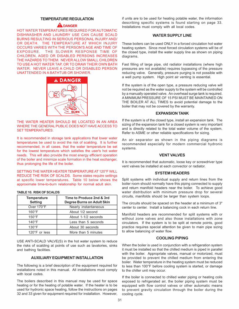
31
TEMPERATURE REGULATION
DANGERHOT WATER TEMPERATURES REQUIRED FOR AUTOMATICDISHWASHER AND LAUNDRY USE CAN CAUSE SCALDBURNS RESULTING IN SERIOUS PERSONAL INJURY AND/OR DEATH. THE TEMPERATURE AT WHICH INJURYOCCURS VARIES WITH THE PERSON'S AGE AND TIME OFEXPOSURE. THE SLOWER RESPONSE TIME OFCHILDREN, AGED OR DISABLED PERSONS INCREASESTHE HAZARDS TO THEM. NEVER ALLOW SMALL CHILDRENTO USE A HOT WATER TAP, OR TO DRAW THEIR OWN BATHWATER. NEVER LEAVE A CHILD OR DISABLED PERSONUNATTENDED IN A BATHTUB OR SHOWER.
THE WATER HEATER SHOULD BE LOCATED IN AN AREAWHERE THE GENERAL PUBLIC DOES NOT HAVE ACCESS TOSET TEMPERATURES.
It is recommended in storage tank applications that lower watertemperatures be used to avoid the risk of scalding. It is furtherrecommended, in all cases, that the water temperature be setfor the lowest temperature which satisfies the user's hot waterneeds. This will also provide the most energy efficient operationof the boiler and minimize scale formation in the heat exchanger,thus prolonging the life of the boiler.
SETTING THE WATER HEATER TEMPERATURE AT 120°F WILLREDUCE THE RISK OF SCALDS. Some states require settingsat specific lower temperatures. Table 10 below shows theapproximate time-to-burn relationship for normal adult skin.
TABLE 10. RISK OF SCALDSTemperature Time to Produce 2nd & 3rd
Setting Degree Burns on Adult SkinOver 170°F Nearly instantaneous160°F About 1/2 second150°F About 1-1/2 seconds140°F Less than 5 seconds130°F About 30 seconds120°F or less More than 5 minutes
USE ANTI-SCALD VALVE(S) in the hot water system to reducethe risks of scalding at points of use such as lavatories, sinksand bathing facilities.
AUXILIARY EQUIPMENT INSTALLATION
The following is a brief description of the equipment required forinstallations noted in this manual. All installations must complywith local codes.
The boilers described in this manual may be used for spaceheating or for the heating of potable water. If the heater is to beused for hydronic space heating, follow the instructions on pages32 and 33 given for equipment required for installation. However,
if units are to be used for heating potable water, the informationdescribing specific systems is found starting on page 33.Installations must comply with all local codes.
WATER SUPPLY LINE
These boilers can be used ONLY in a forced circulation hot waterheating system. Since most forced circulation systems will be ofthe closed type, install the water supply line as shown on pipingdiagrams.
Fast filling of large pipe, old radiator installations (where highpressures are not available) requires bypassing of the pressurereducing valve. Generally, pressure purging is not possible witha well pump system. High point air venting is essential.
If the system is of the open type, a pressure reducing valve willnot be required as the water supply to the system will be controlledby a manually operated valve. An overhead surge tank is required.A MINIMUM PRESSURE OF 15 PSI MUST BE MAINTAINED ONTHE BOILER AT ALL TIMES to avoid potential damage to theboiler that may not be covered by the warranty.
EXPANSION TANKIf the system is of the closed type, install an expansion tank. Thesizing of the expansion tank for a closed system is very importantand is directly related to the total water volume of the system.Refer to ASME or other reliable specifications for sizing.
An air separator as shown in the piping diagrams isrecommended especially for modern commercial hydronicsystems.
VENT VALVESIt is recommended that automatic, loose key or screwdriver typevent valves be installed at each convector or radiator.
SYSTEM HEADERSSplit systems with individual supply and return lines from theboiler room should normally have this piping connected to supplyand return manifold headers near the boiler. To achieve goodwater distribution with minimum pressure drop for severalcircuits, manifolds should be larger than system loops.
The circuits should be spaced on the header at a minimum of 3"center to center. Install a balancing cock in each return line.
Manifold headers are recommended for split systems with orwithout zone valves and also those installations with zonecirculators. If the system is to be split at remote points, goodpractice requires special attention be given to main pipe sizingto allow balancing of water flow.
COOLING PIPING
When the boiler is used in conjunction with a refrigeration systemit must be installed so that the chilled medium is piped in parallelwith the boiler. Appropriate valves, manual or motorized, mustbe provided to prevent the chilled medium from entering theboiler. Water temperature in the heating system must be reducedto less than 100°F before cooling system is started, or damageto the chiller unit may occur.
If the boiler is connected to chilled water piping or heating coilsexposed to refrigerated air, the boiler piping system must beequipped with flow control valves or other automatic meansto prevent gravity circulation through the boiler during thecooling cycle.
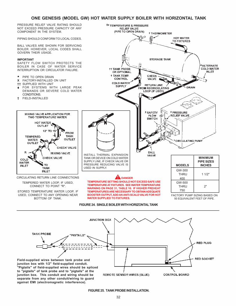
32
ONE GENESIS (MODEL GW) HOT WATER SUPPLY BOILER WITH HORIZONTAL TANK
FIGURE 24. SINGLE BOILER WITH HORIZONTAL TANK
FIGURE 25. TANK PROBE INSTALLATION.
PRESSURE RELIEF VALVE RATING SHOULDNOT EXCEED PRESSURE CAPACITY OF ANYCOMPONENT IN THE SYSTEM.
PIPING SHOULD CONFORM TO LOCAL CODES.
BALL VALVES ARE SHOWN FOR SERVICINGBOILER. HOWEVER, LOCAL CODES SHALLGOVERN THEIR USAGE.
IMPORTANTSAFETY FLOW SWITCH PROTECTS THEBOILER IN CASE OF WATER SERVICEINTERRUPTION OR CIRCULATOR FAILURE.
PIPE TO OPEN DRAINX FACTORY-INSTALLED ON UNIT†† SUPPLIED WITH UNIT
FOR SYSTEMS WITH LARGE PEAKDEMANDS OR SEVERE COLD WATERCONDITIONS.
† FIELD-INSTALLED
INSERT A
Field-supplied wires between tank probe andjunction box with 1/2" field-supplied conduit."Pigtails" of field-supplied wires should be splicedto "pigtails" of tank probe and to "pigtails" at thejunction box. This conduit and wiring should beseparate from any other conduit/wiring to guardagainst EMI (electromagnetic interference).
DANGERTEMPERATURE SETTING SHOULD NOT EXCEED SAFE USETEMPERATURE AT FIXTURES. SEE WATER TEMPERATUREWARNING ON PAGE 31, TABLE 10. IF HIGHER PREHEATTEMPERATURES ARE NECESSARY TO OBTAIN ADEQUATEBOOSTER OUTPUT, ADD AN ANTI-SCALD VALVE FOR HOTWATER SUPPLIED TO FIXTURES.
INSTALL THERMAL EXPANSIONTANK OR DEVICE ON COLD WATERSUPPLY LINE, IF CHECK VALVE ORPRESSURE REDUCING VALVE ISUSED IN SUPPLY.
FACTORY PUMP SIZING BASED ON50 EQUIVALENT FEET OF PIPE.
MINIMUMPIPE SIZES
MODELS INCHES
CIRCULATING RETURN LINE CONNECTIONS
TEMPERED WATER LOOP, IF USED,CONNECT TO POINT "R".
STORED TEMPERATURE WATER LOOP, IFUSED, CONNECT TO ANY OPENING NEAR
BOTTOM OF TANK.
GW-300 THRU 1 1/2" 400 GW-500 THRU 2" 750
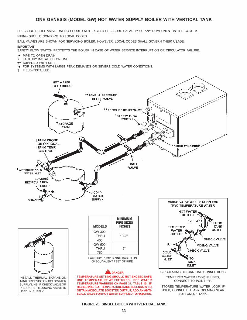
33
ONE GENESIS (MODEL GW) HOT WATER SUPPLY BOILER WITH VERTICAL TANK
FIGURE 26. SINGLE BOILER WITH VERTICAL TANK.
PRESSURE RELIEF VALVE RATING SHOULD NOT EXCEED PRESSURE CAPACITY OF ANY COMPONENT IN THE SYSTEM.
PIPING SHOULD CONFORM TO LOCAL CODES.
BALL VALVES ARE SHOWN FOR SERVICING BOILER. HOWEVER, LOCAL CODES SHALL GOVERN THEIR USAGE.
IMPORTANTSAFETY FLOW SWITCH PROTECTS THE BOILER IN CASE OF WATER SERVICE INTERRUPTION OR CIRCULATOR FAILURE.
PIPE TO OPEN DRAINX FACTORY INSTALLED ON UNIT†† SUPPLIED WITH UNIT
FOR SYSTEMS WITH LARGE PEAK DEMANDS OR SEVERE COLD WATER CONDITIONS.† FIELD-INSTALLED
INSERT A
FACTORY PUMP SIZING BASED ON50 EQUIVALENT FEET OF PIPE.
DANGERTEMPERATURE SETTING SHOULD NOT EXCEED SAFEUSE TEMPERATURE AT FIXTURES. SEE WATERTEMPERATURE WARNING ON PAGE 31, TABLE 10. IFHIGHER PREHEAT TEMPERATURES ARE NECESSARY TOOBTAIN ADEQUATE BOOSTER OUTPUT, ADD AN ANTI-SCALD VALVE FOR HOT WATER SUPPLIED TO FIXTURES.
INSTALL THERMAL EXPANSIONTANK OR DEVICE ON COLD WATERSUPPLY LINE, IF CHECK VALVE ORPRESSURE REDUCING VALVE ISUSED IN SUPPLY.
CIRCULATING RETURN LINE CONNECTIONS
TEMPERED WATER LOOP, IF USED,CONNECT TO POINT "R".
STORED TEMPERATURE WATER LOOP, IFUSED, CONNECT TO ANY OPENING NEAR
BOTTOM OF TANK.
MINIMUMPIPE SIZES
MODELS INCHES GW-300 THRU 1 1/2" 400 GW-500 THRU 2" 750
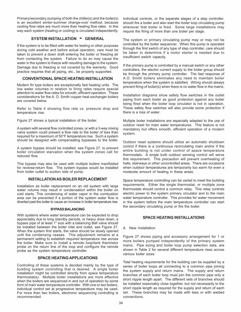
34
Individual controls, or the separate stages of a step controller,should fire a boiler and also start the boiler loop circulating pumpwhenever that boiler is fired. Some large installations mayrequire the firing of more than one boiler per stage.
The system or primary circulating pump may or may not becontrolled by the boiler sequencer. When this pump is operatedthrough the first switch of any type of step controller, care shouldbe taken to determine if a motor starter is needed due toinsufficient switch capacity.
If the primary pump is controlled by a manual switch or any othercontrollers, the electric current supply to the boiler group shouldbe through the primary pump controller. The fast response ofA.O. Smith boilers eliminates any need to maintain boilertemperature when the system is satisfied. Wiring should alwaysprevent firing of boiler(s) when there is no water flow in the mains.
Installation diagrams show safety flow switches in the outletpiping from each boiler as good protection against any boilerbeing fired when the boiler loop circulator is not in operation.These safety flow switches will also provide some protection ifthere is a loss of water.
Multiple boiler installations are especially adapted to the use ofoutdoor reset for main water temperatures. This feature is notmandatory but offers smooth, efficient operation of a modernsystem.
Outdoor reset systems should utilize an automatic shutdowncontrol if there is a continuous recirculating main and/or if theentire building is not under control of space temperaturethermostats. A single bulb outdoor sensing control will servethis requirement. This precaution will prevent overheating ofhalls, stairways or other uncontrolled areas. There are occasionswhen outdoor temperatures are temporarily too warm for even amoderate amount of heating in these areas.
Space temperature controlling can be varied to meet the buildingrequirements. Either the single thermostat, or multiple zonethermostats should control a common relay. This relay controlselectric power to the system primary circulator and to the mainwater temperature controller. This provides for water movementin the system before the main temperature controller can startthe secondary circulating pump or fire the boiler.
SPACE HEATING INSTALLATIONS
A. New Installation
Figure 27 shows piping and accessory arrangement for 1 ormore boilers pumped independently of the primary systemmains. Pipe sizing and boiler loop pump selection data, areshown in Table 2 for several different temperature rises acrossvarious boiler sizes.
Total heating requirements for the building can be supplied by aseries of boiler loops all connecting to a common pipe joiningthe system supply and return mains. The supply and returnbranches of each boiler loop must join the common pipe only ashort nipple length apart. The different sets of branches shouldbe installed reasonably close together, but not necessarily to theshort nipple length as required for the supply and return of eachset. These branches may be made with tees or with weldedconnections.
Primary/secondary pumping of both the chiller(s) and the boiler(s)is an excellent winter-summer change-over method, becausecooling flow rates are much more than heating flow rates. In thisway each system (heating or cooling) is circulated independently.
SYSTEM INSTALLATION - GENERALIf the system is to be filled with water for testing or other purposesduring cold weather and before actual operation, care must betaken to prevent a down draft entering the boiler or freezing airfrom contacting the system. Failure to do so may cause thewater in the system to freeze with resulting damage to the system.Damage due to freezing is not covered by the warranty. Goodpractice requires that all piping, etc., be properly supported.
CONVENTIONAL SPACE HEATING INSTALLATIONModern fin type boilers are exceptionally fast heating units. Thelow water volumes in relation to firing rates require specialattention to water flow rates for smooth, efficient operation. Theseconsiderations for the A. O. Smith copper heat exchanger boilersare covered below.
Refer to Table 4 showing flow rate vs. pressure drop andtemperature rise.
Figure 27 shows a typical installation of the boiler.
A system with several flow controlled zones, or with a 3-way mixingvalve system could present a flow rate to the boiler of less thanrequired for a maximum of 50°F temperature rise. Such a systemshould be designed with compensating bypasses to the boiler.
A system bypass should be installed, see Figure 27, to preventboiler circulation starvation when the system zones call forreduced flow.
This bypass may also be used with multiple boilers manifoldedfor reverse-return flow. The system bypass would be installedfrom boiler outlet to suction side of pump.
INSTALLATION AS BOILER REPLACEMENTInstallation as boiler replacement on an old system with largewater volume may result in condensation within the boiler oncold starts. This condensing of water vapor in the combustionarea can be prevented if a portion of the system water flow isdiverted past the boiler to cause an increase in boiler temperature rise.
BYPASS BALANCINGWith systems where water temperature can be expected to dropappreciably due to long standby periods, or heavy draw down, abypass pipe of at least 1" size with a balancing Ball valve shouldbe installed between the boiler inlet and outlet, see Figure 27.When the system first starts, the valve should be slowly openeduntil the condensing ceases. This adjustment remains at apermanent setting to establish required temperature rise acrossthe boiler. Make sure to install a remote loop/tank thermistorprobe on the return line of the loop and configure the remoteprobe as the system temperature controller.
SPACE HEATING APPLICATIONS
Controlling of these systems is decided mainly by the type ofbuilding system controlling that is desired. A single boilerinstallation might be controlled directly from space temperaturethermostat(s). Multiple boiler installations are more effectivewhen the boilers are sequenced in and out of operation by someform of main water temperature controller. With one or two boilers,individual control set at progressive temperature may be used.For more than two boilers, electronic sequencing controlling isrecommended.
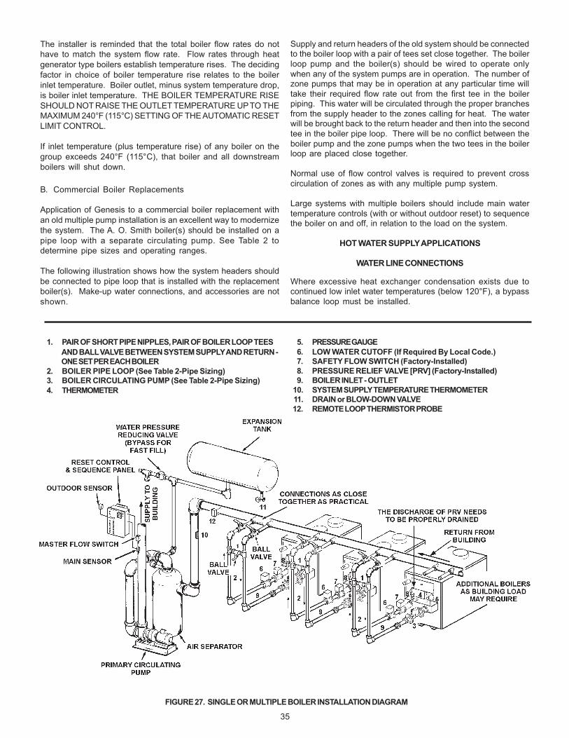
35
Supply and return headers of the old system should be connectedto the boiler loop with a pair of tees set close together. The boilerloop pump and the boiler(s) should be wired to operate onlywhen any of the system pumps are in operation. The number ofzone pumps that may be in operation at any particular time willtake their required flow rate out from the first tee in the boilerpiping. This water will be circulated through the proper branchesfrom the supply header to the zones calling for heat. The waterwill be brought back to the return header and then into the secondtee in the boiler pipe loop. There will be no conflict between theboiler pump and the zone pumps when the two tees in the boilerloop are placed close together.
Normal use of flow control valves is required to prevent crosscirculation of zones as with any multiple pump system.
Large systems with multiple boilers should include main watertemperature controls (with or without outdoor reset) to sequencethe boiler on and off, in relation to the load on the system.
HOT WATER SUPPLY APPLICATIONS
WATER LINE CONNECTIONS
Where excessive heat exchanger condensation exists due tocontinued low inlet water temperatures (below 120°F), a bypassbalance loop must be installed.
The installer is reminded that the total boiler flow rates do nothave to match the system flow rate. Flow rates through heatgenerator type boilers establish temperature rises. The decidingfactor in choice of boiler temperature rise relates to the boilerinlet temperature. Boiler outlet, minus system temperature drop,is boiler inlet temperature. THE BOILER TEMPERATURE RISESHOULD NOT RAISE THE OUTLET TEMPERATURE UP TO THEMAXIMUM 240°F (115°C) SETTING OF THE AUTOMATIC RESETLIMIT CONTROL.
If inlet temperature (plus temperature rise) of any boiler on thegroup exceeds 240°F (115°C), that boiler and all downstreamboilers will shut down.
B. Commercial Boiler Replacements
Application of Genesis to a commercial boiler replacement withan old multiple pump installation is an excellent way to modernizethe system. The A. O. Smith boiler(s) should be installed on apipe loop with a separate circulating pump. See Table 2 todetermine pipe sizes and operating ranges.
The following illustration shows how the system headers shouldbe connected to pipe loop that is installed with the replacementboiler(s). Make-up water connections, and accessories are notshown.
FIGURE 27. SINGLE OR MULTIPLE BOILER INSTALLATION DIAGRAM
1. PAIR OF SHORT PIPE NIPPLES, PAIR OF BOILER LOOP TEESAND BALL VALVE BETWEEN SYSTEM SUPPLY AND RETURN -ONE SET PER EACH BOILER
2. BOILER PIPE LOOP (See Table 2-Pipe Sizing)3. BOILER CIRCULATING PUMP (See Table 2-Pipe Sizing)4. THERMOMETER
5. PRESSURE GAUGE6. LOW WATER CUTOFF (If Required By Local Code.)7. SAFETY FLOW SWITCH (Factory-Installed)8. PRESSURE RELIEF VALVE [PRV] (Factory-Installed)9. BOILER INLET - OUTLET
10. SYSTEM SUPPLY TEMPERATURE THERMOMETER11. DRAIN or BLOW-DOWN VALVE12. REMOTE LOOP THERMISTOR PROBE

36
HARD WATER CONDITIONS
Where hard water conditions exist, water softening or thethreshold type of water treatment is recommended. This willprotect the dishwashers, coffee urns, water heaters, water pipingand other equipment. When water softening or water treatmentis not practical, a comparatively easy method of periodic limeremoval from the unit must be employed.
WARNINGLime accumulation can reduce the life of the equipment, reduceefficiency and waste fuel. Boiler failure due to lime or scalebuildup voids the warranty.
INTERNAL CONTAMINANTS
The system must be internally cleaned and flushed after a newor replacement unit has been installed to remove contaminantsthat may have accumulated during installation. This is doublyimportant when a replacement unit is installed into an existingsystem where Stop Leak or other boiler additives have beenused.
All systems should be completely flushed with a grease removingsolution to assure trouble-free operation. Pipe joint compounds,soldering paste, grease on tubing and pipe all tend tocontaminate a system.
Failure to clean and flush the system can cause solids to formon the inside of the heat exchanger, can produce acidconcentrations that become corrosive, can allow excessiveamounts of air or other gases to form which could blockcirculation, foul system accessories and damage circulator sealsand impellers.
It is recommended that after installation, the boiler and systemwhen filled should include the proper percentage of cleaningsolution related to approximate water volume of the system. Fireand circulate for about one hour and then flush clean with freshwater. Commercial grease removing solutions are available.
Before operating the boiler, the entire system must be filled withwater, purged of air and checked for leaks. Do not use Stop Leakor other boiler compounds. The gas piping must also be leak tested.
PRECAUTIONSIf the unit is exposed to the following, do not operate boiler untilall corrective steps have been made by a qualified serviceman:
1. Exposure to fire.2. If damaged.3. Firing without water.4. Sooting.
If the heater has been exposed to flooding it must be replaced.
IMPORTANTONLY QUALIFIED PERSONNEL SHALL PERFORM THE INITIALFIRING OF THE HEATER. AT THIS TIME THE USER SHOULDNOT HESITATE TO ASK THE INDIVIDUAL ANY QUESTIONSREGARDING THE OPERATION AND MAINTENANCE OF THE UNIT.
FILLING AND VENTING
1. Fast fill system through bypass until pressure approachesdesired system pressure. Close bypass valve and permitpressure to be established by the pressure reducing valve.
2. Vent all high points in system to purge system of air.
Provisions should be made to permit manual venting of radiatorsor convectors.
IMPORTANTUNDER NO CIRCUMSTANCES SHALL THE GAS PRESSUREMEASURED AT THE BURNER MANIFOLD EXCEED THATSTATED ON THE BOILER RATING PLATE. OVERFIRING WILLRESULT IN DAMAGE TO THE BOILER, AS WELL AS INCREASEDRISK OF FIRE, SOOTING AND ASPHYXIATION.
MAIN BURNERS
Check main burners every three months for proper flamecharacteristics.
The main burner should display the following characteristics:
• Provide complete combustion of gas.
• Cause rapid ignition and carry over of flame across entireburner.
• Give reasonably quiet operation during initial ignition,operation and extinction.
• Cause no excessive lifting of flame from burner ports, seeFigure 1.
If the preceding burner characteristics are not evident, check foraccumulation of lint or other foreign material that restricts or blocksthe air openings to the burner or boiler.
NOTE: Cleaning of main burners. Shut off all gas and electricityto unit.
1. Remove main burners from unit.
2. Check that burner venturi and ports are free of foreign matter.
3. Clean burners with bristle brush and/or vacuum cleaner.DO NOT distort burner ports.
4. Reinstall burners in unit. Ensure that all the screws on theburner flange are tightened securely so that the gasket willprovide a good seal. Also, ensure that each orifice is centeredwith the venturi opening of every burner. Also check for goodflow of combustion and ventilating air to the unit.
Also check for good flow of combustion and ventilating air to theunit.
After placing the boiler in operation, check the ignition systemsafety shut-off devices for proper operation. To accomplish thiswith the main burners operating, close the valve on the manifold.Within four seconds the main burners should extinguish. If thisdoes not occur, discontinue gas supply by closing main manualshut-off and call a qualified serviceman to correct the situation. Ifthe burners extinguish, then light boiler in accordance with lightingand operating instructions.
For installations above 2000 feet (600 m), refer to HIGH ALTITUDEINSTALLATIONS in the installation section.
PRE-TROUBLESHOOTING
Before any extensive troubleshooting, ensure that:
• Power (120 VAC) is supplied to the appliance.
37
• System control (tank probe, thermostat, etc.) is calling forappliance operation (call for heat).
• Other contacts (switches) are closed (low water cutoff, flowswitch, limit controls, pressure switches, etc.)
• Gas supply pressure is within the maximum and minimumoperating ranges listed on the appliance rating plate/label.
• Appliance is wired according to wiring diagram.
NOTE: Shorting the thermostat wiring to ground in the 24 voltcircuit will blow the 3 amp fuse.
• All wire terminals/connectors are firmly attached to valves,modules, switches, limit controls, etc.
• There has been no damage caused by freezing, inoperativepumps, etc.
DESCRIPTION OF COMPONENTS
DIFFERENTIAL PRESSURE SWITCH
The differential pressure switch ensures that a sufficientdifferential exists between the air pressure in the pre-mix chamberand the inlet of the burner for safe, low NOx combustion. Theswitch has two pressure taps marked "+" (positive) and "-"(negative). Silicone tubing is run from the positive pressure tapof the switch to a tap on the control panel to measure the airpressure in the pre-mix chamber. The negative pressure tapmeasures the pressure taken at the burner's auxiliary tube.Connections can be seen by removing the lower front jacketpanel. It is important that this panel remain sealed at all timeswhile the boiler is operating.
BLOCKED FLUE PRESSURE SWITCH
The blocked flue pressure switch ensures that the flue gas ventis clear. This pressure switch is normally closed and only openson the fault conditions.
FLAME SENSOR
The flame sensor acts to prove the flame has carried over fromthe ignitor to the right-most burner of stage 1. If no flame issensed, the gas valve(s) will close automatically. And If no flameis sensed on three (or one) ignition trials the boiler will lock out.Upon lockout, manually push the SELECT button on the UIM torestart the boiler.
WATER FLOW SWITCH
The Water Flow Switch is installed at the boiler outlet to preventburner operation in the event of inadequate water flow throughthe boiler. The Water Flow Switch is a single pole, normally openswitch that will close its contacts when increasing water flowrate is encountered. This switch is factory-set, but may requirefield adjustment. The contacts will open when the flow rate dropsbelow the adjusted setting and the gas valve(s) will close turningoff the gas to the burners.
LIMIT CONTROLS
This boiler contains two limit controls built into the outlet waterprobe. The automatic reset limit is adjustable from 90°F to 235°F.
The manual reset limit is factory-set at 250°F. Once the manuallyreset limit opens, the gas valve(s) will close and the boiler will
lockout. Upon lockout, manually push the SELECT push-buttonon the UIM to restart the boiler.
ON/OFF SWITCH
The ON/OFF switch is a single-pole, single-throw rocker switch.The switch provides 120VAC from the line source to the boiler.
COMBUSTION AIR BLOWER
The bearings in the motor are pre-lubricated and sealed at thefactory. No further oiling of the bearings is required for the life ofthe motor.
GENERAL MAINTENANCE
These boilers are designed to give many years of efficientand satisfactory service when properly operated andmaintained. To assure continued good performance, thefollowing recommendations are made.
The area around the unit should be kept clean and free from lintand debris. Sweeping the floor around the boiler should bedone carefully. This will reduce the dust and dirt which may enterthe burner and heat exchanger, causing improper combustionand sooting.
THE FLOW OF COMBUSTION AIR TO THE BOILER MUST NOT BEOBSTRUCTED.
THE BOILER AREA MUST BE KEPT CLEAR AND FREE FROMCOMBUSTIBLE MATERIALS, GASOLINE AND OTHERFLAMMABLE VAPORS AND LIQUIDS.
Any safety devices including low water cutoffs used in conjunctionwith this boiler should receive periodic (every six months)inspection to assure proper operation. A low water cutoff deviceof the float type should be flushed every six months.
Periodic checks, at least twice a year, should be made for waterand/or gas leaks.
More frequent inspections may be necessary depending on waterconditions.
The boiler-mounted gas and electrical controls have beendesigned to give both dependable service and long life. However,malfunction can occur, as with any piece of equipment. It istherefore recommended that all components be checkedperiodically by a qualified serviceman for proper operation.
RELIEF VALVE
The safety relief valve should be opened at least twice a year tocheck its working condition. This will aid in assuring properpressure relief protection. Lift the lever at the top of the valveseveral times until the valve seats properly and operates freely.
DANGERTHE WATER PASSING OUT OF THE VALVE DURING CHECKINGOPERATION MAY BE EXTREMELY HOT. BEFORE OPERATINGRELIEF VALVE, MAKE SURE DRAIN LINE IS INSTALLED TO DIRECTDISCHARGE TO A SAFE LOCATION SUCH AS AN OPEN DRAIN,TO AVOID SCALDING OR WATER DAMAGE.
38
WARNINGSHOULD OVERHEATING OCCUR OR THE GAS SUPPLY FAILTO SHUT OFF, TURN OFF THE MANUAL GAS CONTROL VALVETO THE APPLIANCE.
COMBUSTION AIR FILTER
If the combustion air supply to the boiler contains dust, dirt, drywalldust etc., a filter must be installed. Air filter is not supplied withthe boiler as shipped from the factory. The installer must providea filtering system in the air inlet to the boiler if dust, dirt orconstruction dirt can be pulled into the boiler through the inlet airpiping.
BLOWER COMPARTMENT
The blower compartment should be cleaned annually to removeany dirt and lint that may have accumulated in the compartmentor on the blower and motor. Buildups of dirt and lint on theblower and motor can create excessive loads on the motorresulting in higher that normal operating temperatures andpossible shortened service life.
VENTING MAINTENANCE
It is recommended that the intake and exhaust piping of theappliance be checked every 3 months for dust, condensateleakage, deterioration and carbon deposits.
Qualified serviceman should follow this procedure when theboiler's intake and exhaust piping need cleaning.
WARNINGDO NOT USE A NYLON BRUSH OR OTHER STATIC CREATINGMATERIAL TO CLEAN DUST AND CARBON DEPOSITS FROMHEATING SURFACES AND VENT.
SUCH DEPOSITS ARE FLAMMABLE AND MAY BE IGNITED BYSTATIC ELECTRICITY. USE A METAL BRUSH TO MINIMIZE THEDANGER OF EXPLOSION.
1. Turn off the electrical power, and manual gas shut-off.
• Allow boiler parts to cool before disassembly.
2. Remove the vent pipe.
• Check parts and chimney for obstructions and clean asnecessary.
3. Remove burners from boiler and other metal parts asrequired to clean as necessary.
• Refer to parts list supplied with this manual fordisassembly aid.
4. Clean and reinstall the parts removed in steps 2 and 3.
• Be sure the vent pipe has a minimum upward pitch ofone quarter inch per foot of length and is sealed asnecessary.
5. Restore electrical power and gas supply to boiler.
• Check for gas leaks and proper boiler and vent operation.
HEAT EXCHANGER PREVENTIVE MAINTENANCE
In most water supply systems some solids exist. As the water isheated, these tend to drop out depositing as scale or lime. Thisscale must be removed before the heat exchanger tubes becomeblocked.
CAUTIONLime accumulation can reduce the life of the equipment, reduceefficiency and waste fuel. Boiler failure due to lime or scalebuildup voids the warranty.
See section on CIRCULATING PUMP to ensure you have selectedthe proper size pump for your situation.
DELIMING
The amount of calcium carbonate (lime) released from water isin direct proportion to water temperature and usage. The higherthe water temperature or water usage, the more lime depositsare dropped out of the water. This is the lime scale which formsin pipes, boilers and on cooking utensils.
The usage of water softening equipment greatly reduces thehardness of water. However, this equipment does notalways remove all of the hardness (lime). For this reason it isrecommended that a regular schedule for deliming bemaintained.
The time between cleaning will vary from two to six monthsdepending upon water conditions and usage. A change ofapproximately 5°F in the normal temperature rise through theboiler is usually an indication that scale should be removed. Forlong life, copper or brass is recommended for all valves, pipeand fittings.
TUBE CLEANING PROCEDUREMECHANICAL REMOVAL OF DEPOSITS
Establish a regular inspection schedule, the frequency dependson the local water conditions and severity of service. Do not letthe tubes clog up solidly. Clean out deposits over 1/16 inchthickness.
To service heat exchanger tubes remove return header casting,side opposite the water connections. Use a standard 9/16" deepsocket ratchet to remove the nuts, exposing the tube ends. Inspectto ensure tubes are free of scale and deposits. If scaled, removedeposits with a stiff wire brush or mechanical tube cleaner tobare metal. Install new O rings and reinstall return header casting.Flush system.
Note: Removal of the heat exchanger is not required.
CAUTIONIf heat exchanger maintenance requires tubing replacement,special provisions shall be taken to ensure that the damagedtubes are carefully removed.
Replacement tubes must be properly installed and expandedinto the tube plate.
Over rolling, misalignment of tubes or improper tightening of theassembly may result in leaks or damage to the heat exchanger.Contact your A. O. Smith dealer for detailed instructions.

39
Before starting the boiler please review the Boiler’s Instruction Manual (AOS Part Number 212130-002) supplied with theboiler. This is a powered combustion copper tube boiler. If you are not familiar with a powered combustion boiler pleasecontact an authorized A.O. Smith representative before starting the unit.
This boiler is equipped with an EMC5000 control system. The EMC5000 displays the system status and errors that mayoccur during normal operation. For full details on the controls please refer to the Instruction Manual supplied with the boiler.The boiler must be installed according to the Installation Instructions provided with the unit. Failure to do so will void thewarranty.
Prior to starting the boiler for the first time check the following:
Before applying gas or water to the system, the power line electrical hook-up can be verified. If connected, remove the plugin connectors (J1, J2, J3) on the Power Distribution Board (PDB) and place the jumper (JP1) on the PDB in the “Test” position.(Note: Leaving the connectors connected during this test will product invalid light indications that will not match the table.)
Apply electrical power to the system and observe the three colored LED’s on the PDB. Verify that the proper light turns onaccording to the following table:
When connections are correct, turn off power, move jumper to “Run” position, and reconnect cables to PDB.(Note: With the jumper in the “Run” position, only the Green LED functions.)
Prior to turning on the gas, proper operation of much of the system can be verified. With the water turned on, startthe system and allow it to run through a heating cycle. It should stop when it checks for flame and declare a fault.This will verify that the pump, flow switch, igniter, gas valve, blower and blower differential pressure switch areall functioning.
Gas Supply Lines are sized in accordance with ANSI Z223.1 National Fuel Gas Code or CAN/CSA-B149.1(current edition).
Minimum Inlet Gas Supply Pressure of 5.5” W.C. for Natural Gas or 11.0” W.C. for Propane.
Check all gas supply lines for leaks.
Check that all venting is properly sealed in accordance with the Instruction Manual.
Main power is dedicated 120 VAC, 60Hz, single phase, rated for 20 Amps.
Turn “ON” gas and water supply to the boiler ( DO NOT DRY FIRE THE BOILER ).
Purge air from the gas and water lines.
Make sure the boiler is not damaged. If the unit is damaged contact an A.O. Smith representative for service or replacementparts prior to starting the boiler.
COPPER BOILERS FOR HYDRONIC HEATING AND HOT WATER SUPPLYSERIES 400, 401,402, 403, 404, 405, 2-Stage Units
Start-up Instructions
PLACE THESE INSTRUCTIONS ADJACENT TO BOILER AND NOTIFY OWNER TO KEEP FOR FUTURE REFERENCE.
Line Connection Status Green LED Red LED Yellow LEDProper connections (On) Off (On)Open Ground Off (On) OffReverse Polarity (On) (On) OffOpen Hot Off Off OffOpen Neutral (On) (On) (On)Reverse Hot & Ground Off (On) (On)Hot on Neutral with Hot Open Off (On) Off
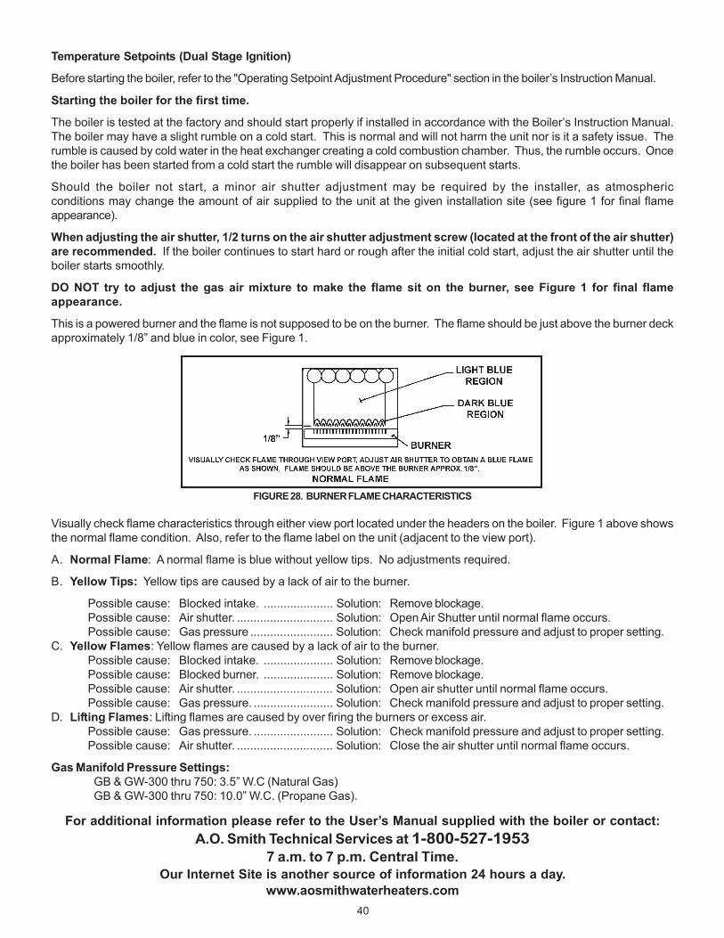
40
Temperature Setpoints (Dual Stage Ignition)
Before starting the boiler, refer to the "Operating Setpoint Adjustment Procedure" section in the boiler’s Instruction Manual.
Starting the boiler for the first time.
The boiler is tested at the factory and should start properly if installed in accordance with the Boiler’s Instruction Manual.The boiler may have a slight rumble on a cold start. This is normal and will not harm the unit nor is it a safety issue. Therumble is caused by cold water in the heat exchanger creating a cold combustion chamber. Thus, the rumble occurs. Oncethe boiler has been started from a cold start the rumble will disappear on subsequent starts.
Should the boiler not start, a minor air shutter adjustment may be required by the installer, as atmosphericconditions may change the amount of air supplied to the unit at the given installation site (see figure 1 for final flameappearance).
When adjusting the air shutter, 1/2 turns on the air shutter adjustment screw (located at the front of the air shutter)are recommended. If the boiler continues to start hard or rough after the initial cold start, adjust the air shutter until theboiler starts smoothly.
DO NOT try to adjust the gas air mixture to make the flame sit on the burner, see Figure 1 for final flameappearance.
This is a powered burner and the flame is not supposed to be on the burner. The flame should be just above the burner deckapproximately 1/8” and blue in color, see Figure 1.
FIGURE 28. BURNER FLAME CHARACTERISTICS
Visually check flame characteristics through either view port located under the headers on the boiler. Figure 1 above showsthe normal flame condition. Also, refer to the flame label on the unit (adjacent to the view port).
A. Normal Flame: A normal flame is blue without yellow tips. No adjustments required.
B. Yellow Tips: Yellow tips are caused by a lack of air to the burner.
Possible cause: Blocked intake. ..................... Solution: Remove blockage.Possible cause: Air shutter. ............................. Solution: Open Air Shutter until normal flame occurs.Possible cause: Gas pressure ......................... Solution: Check manifold pressure and adjust to proper setting.
C. Yellow Flames: Yellow flames are caused by a lack of air to the burner.Possible cause: Blocked intake. ..................... Solution: Remove blockage.Possible cause: Blocked burner. ..................... Solution: Remove blockage.Possible cause: Air shutter. ............................. Solution: Open air shutter until normal flame occurs.Possible cause: Gas pressure. ........................ Solution: Check manifold pressure and adjust to proper setting.
D. Lifting Flames: Lifting flames are caused by over firing the burners or excess air.Possible cause: Gas pressure. ........................ Solution: Check manifold pressure and adjust to proper setting.Possible cause: Air shutter. ............................. Solution: Close the air shutter until normal flame occurs.
Gas Manifold Pressure Settings:GB & GW-300 thru 750: 3.5” W.C (Natural Gas)GB & GW-300 thru 750: 10.0” W.C. (Propane Gas).
For additional information please refer to the User’s Manual supplied with the boiler or contact:A.O. Smith Technical Services at 1-800-527-1953
7 a.m. to 7 p.m. Central Time.Our Internet Site is another source of information 24 hours a day.
www.aosmithwaterheaters.com

41
NOTES

42
NOTES
43
NEW BOILER LIMITED WARRANTYA. O. Smith Corporation, the warrantor, extends the following LIMITED WARRANTY to the owner of this hot water boiler:
1. If within TEN years after initial installation of the boiler, the heat exchanger shall prove upon examination by the warrantor to be defective inmaterial or workmanship, the warrantor, at his option, will exchange or repair such part or portion. This term is reduced to FIVE years if this boileris used for volume hot water supply purposes other than hydronic space heating.a. This warranty is extended to the owner for all other parts or portion during the FIRST year following initial installation of this boiler.b. The warranty on the repair or replacement of the part or portion will be limited to the unexpired term of the original warranty.
2. CONDITIONS AND EXCEPTIONSThis warranty shall apply only when the boiler is installed in accordance with local plumbing and building codes, ordinances and regulations, theprinted instructions provided with it and good industry practices. In addition, an appropriately sized safety relief valve certified to the ASMEBoiler and Pressure Vessel Code must have been installed and fresh water used for filling and makeup purposes;a. This warranty shall apply only when the boiler is used:
(1) at temperatures not exceeding the maximum setting of its operative and/or high limit control;(2) at water pressure not exceeding the working pressure shown on the boiler;(3) when filled with boiler water, free to circulate at all times and with the heat exchanger free of damaging scale deposits;(4) in a noncorrosive and non-contaminated atmosphere;(5) in the United States, its territories or possessions, and Canada;(6) at a water velocity flow rate, not exceeding or below the Boiler's designed flow rates;
b. Any accident to the boiler, any misuse, abuse (including freezing) or alteration of it, any operation of it in a modified form will void thiswarranty.
3. SERVICE AND REPAIR EXPENSEUnder this limited warranty the warrantor will provide only a replacement part. The owner is responsible for all other costs. Such costs mayinclude but are not limited to:a. Labor charges for service removal, repair or reinstallation of the component part;b. Shipping, delivery, handling, and administrative charges for forwarding the replacement part from the nearest distributor and returning the
claimed defective part to such distributor.c. All cost necessary or incidental for any material and/or permits required for installation of the replacement.
4. LIMITATIONS ON IMPLIED WARRANTIESImplied warranties, including any warranty of merchantability imposed on the sale of this boiler under state law are limited to one (1) yearduration for the boiler or any of its parts. Some states or provinces do not allow limitations on how long an implied warranty lasts, so the abovelimitation may not apply to you.
5. CLAIM PROCEDUREAny claim under the warranty should be initiated with the dealer who sold the boiler, or with any other dealer handling the warrantor’s products.If this is not practical, the owner should contact:
U.S. Customers Canadian CustomersA. O. Smith Water Products Company A. O. Smith Enterprises Ltd.500 Tennessee Waltz Parkway, P. O. Box, 310 - 768 Erie StreetAshland City, TN 37015 Stratford, Ontario N5A 6T3Telephone: 800 323-2636 Telephone: (800) 265-8520
a. The warrantor will only honor replacement with identical or similar parts thereof which are manufactured or distributed by the warrantor.b. Dealer replacements are made subject to in-warranty validation by warrantor.
6. DISCLAIMERSNO OTHER EXPRESS WARRANTY HAS BEEN OR WILL BE MADE ON BEHALF OF THE WARRANTOR WITH RESPECT TO THE MERCHANTABILITYOF THE BOILER OR THE INSTALLATION, OPERATION, REPAIR OR REPLACEMENT OF THE BOILER. THE WARRANTOR SHALL NOT BERESPONSIBLE FOR WATER DAMAGE, LOSS OF USE OF THE UNIT, INCONVENIENCE, LOSS OR DAMAGE TO PERSONAL PROPERTY OR OTHERCONSEQUENTIAL DAMAGE. THE WARRANTOR SHALL NOT BE LIABLE BY VIRTUE OF THIS WARRANTY OR OTHERWISE FOR DAMAGE TOANY PERSONS OR PROPERTY, WHETHER DIRECT OR INDIRECT, AND WHETHER ARISING IN CONTRACT OR TORT.a. Some states or provinces do not allow the exclusion or limitation of the incidental or consequential damage, so the above limitations or
exclusions may not apply to you.b. This warranty gives you specific legal rights, and you may also have other rights which vary from state to state or province to province.
Fill in the following for your own reference. Keep it. Registration is not a condition of warranty. The model and serial number are found on the boiler’srating plate.
Owner _______________________________________________________________________________________________________________
Installation Address _____________________________________________________________________________________________________
City and State or Province ______________________________________________________Postal/Zip Code _______________________________
Date Installed _____________________ Model No. ______________________________________Serial No. __________________________________
Dealer’s Name ___________________________________________________________________________________________________________
Dealer’s Address ________________________________________________________________Phone No. ________________________________
FILL IN WARRANTY AND KEEP FOR FUTURE REFERENCE

44
A DIVISION OF A. O. SMITH CORPORATIONMC BEE, SC., RENTON, WA.,
STRATFORD-ONTARIO, VELDHOVEN-THE NETHERLANDSwww.hotwater.com