copper structured abling design guide … · commercial building cabling standards for copper...
TRANSCRIPT
© Copyright 2014, Belden Inc.
COPPER STRUCTURED CABLING
DESIGN GUIDE Issue 10
1. Introduction ........................................................................................... 1
2. Design Fundamentals ............................................................................. 2
3. Planning Considerations ...................................................................... 11
4. Design Guidelines ................................................................................ 21
5. Installation and Testing Guidelines ...................................................... 57
Annex A: Design Examples – IBDN Unshielded Cabling Systems.............. 63
Annex B: Design Examples – IBDN Shielded Cabling Systems ................. 69
Annex C: HDBaseT Cabling Considerations ............................................... 75
References ............................................................................................... 80


TABLE OF CONTENTS
1. Introduction ................................................................................................................ 1
2. Design Fundamentals .................................................................................................. 2
The Hierarchical Star Model ............................................................................................................... 2
Design Components ........................................................................................................................... 3
Spaces ............................................................................................................................................. 3
Pathways ........................................................................................................................................ 3
Cables ............................................................................................................................................. 3
Connectors ..................................................................................................................................... 3
Cords ............................................................................................................................................... 3
Backbone Design Layouts ................................................................................................................... 4
Horizontal Design Layouts .................................................................................................................. 7
Telecommunications Enclosure ...................................................................................................... 8
Consolidation Point ........................................................................................................................ 9
Multi-User Telecommunications Outlet Assembly ...................................................................... 10
3. Planning Considerations ............................................................................................ 11
Cabling System Performance ........................................................................................................... 11
Topologies ........................................................................................................................................ 12
Two-Connector Topology Using an Interconnect ......................................................................... 13
Three-Connector Topology Using a Cross-Connect ...................................................................... 14
Three-Connector Topology Using an Interconnect and a Consolidation Point ............................ 15
Four-Connector Topology Using a Cross-Connect and a Consolidation Point ............................. 16
Work Area Cord Length Limits When Using MUTOAs .................................................................. 17
Separation from Power Cables and Fluorescent Lighting ................................................................ 18
Temperature and Humidity Requirements ...................................................................................... 20

4. Design Guidelines ......................................................................................................21
Work Area ........................................................................................................................................ 21
Work Area Specifications ............................................................................................................. 22
Examples of Work Area Components .......................................................................................... 24
Consolidation Point (optional) ......................................................................................................... 33
Consolidation Point Specifications ............................................................................................... 33
Examples of Consolidation Point Components ............................................................................ 34
Telecommunications Room ............................................................................................................. 37
Telecommunications Room Specifications .................................................................................. 37
Telecommunications Enclosure (optional) ...................................................................................... 39
Telecommunications Enclosure Specifications ............................................................................ 39
Examples of Telecommunications Room / Telecommunications Enclosure Components .......... 40
Equipment Room ............................................................................................................................. 48
Equipment Room Specifications .................................................................................................. 48
Examples of Equipment Room Components ............................................................................... 49
Entrance Space ................................................................................................................................. 54
Entrance Space Specifications ..................................................................................................... 54
Example of Entrance Space Components .................................................................................... 55
5. Installation and Testing Guidelines ............................................................................57
Introduction ..................................................................................................................................... 57
Extent of Testing .............................................................................................................................. 62
ANNEX A: Design Examples IBDN Unshielded Cabling Systems .....................................63
Design Example 1 — Category 6A .................................................................................................... 64
Design Example 2 — Category 6 ...................................................................................................... 65
Design Example 3 — Category 5e .................................................................................................... 67
ANNEX B: Design Examples IBDN Shielded Cabling Systems.........................................69
Design Example 1 — Category 6A .................................................................................................... 70
Design Example 2 — Category 6 ...................................................................................................... 71
Design Example 3 — Category 5e .................................................................................................... 73
ANNEX C: HDBaseT Cabling Considerations ....................................................................75
References .....................................................................................................................80

FIGURES
Figure 1: Example of a two-tier generic hierarchical star model ................................................ 2
Figure 2: Generic backbone design layout.............................................................................. 4
Figure 3: Generic backbone design layout with multiple Equipment Rooms ................................ 5
Figure 4: Generic campus backbone design layout .................................................................. 6
Figure 5: Generic horizontal design layout ............................................................................. 7
Figure 6: Horizontal design layout with Telecommunications Enclosure...................................... 8
Figure 7: Horizontal design layout with Consolidation Point ...................................................... 9
Figure 8: Horizontal design layout with MUTOA .....................................................................10
Figure 9: Ethernet network topology example .......................................................................12
Figure 10: Two-connector topology using an interconnect.......................................................13
Figure 11: Three-connector topology using a cross-connect ....................................................14
Figure 12: Three-connector topology using an interconnect and a Consolidation Point ................15
Figure 13: Four-connector topology using a cross-connect and a Consolidation Point .................16
Figure 14: T568A and T568B pin/pair assignments—front view of jack .....................................22
Figure 15: KeyConnect single-gang 2-port faceplate ..............................................................24
Figure 16: KeyConnect stainless steel 4-port faceplate for institutional applications ...................24
Figure 17: KeyConnect tamper-resistant 4-port faceplate with locking cover .............................25
Figure 18: KeyConnect modular furniture, Decora, and 106-style adapters ...............................25
Figure 19: KeyConnect double-gang 12-port faceplate ...........................................................26
Figure 20: 12-port Multi-User Outlet Box equipped with modular jacks .....................................26
Figure 21: KeyConnect unshielded modular jacks ..................................................................28
Figure 22: KeyConnect shielded modular jacks ......................................................................29
Figure 23: Work Area unshielded modular cords ....................................................................31
Figure 24: Work Area shielded modular cords .......................................................................31
Figure 25: Category 6A insulation displacement contact connector (10 GX IDC) ........................34
Figure 26: Category 6 insulation displacement contact connector (GigaBIX) .............................34
Figure 27: Category 5e insulation displacement contact connector (BIX) ..................................35
Figure 28: Unshielded cable types .......................................................................................40
Figure 29: Shielded cable types ...........................................................................................41
Figure 30: Unshielded and shielded patch panels—preloaded with modules or empty .................44
Figure 31: Wall-mount and free-standing racks and enclosures ...............................................46
Figure 32: Multi-pair indoor backbone cables—Category 5e and Category 3 ..............................49
Figure 33: GigaBIX Cross-Connect System—patch cord or cross-connect wire (Category 6) ........51
Figure 34: BIX Cross-Connect System—patch cord or cross-connect wire (Category 5e) .............52

Figure 35: 110- Cross-Connect System—patch cord (Category 5e) .......................................... 52
Figure 36: 4-pair gel-filled outside plant cables—Category 6 and Category 5e .......................... 55
Figure 37: Permanent Link testing....................................................................................... 59
Figure 38: Channel testing with an interconnect ................................................................... 60
Figure 39: Channel testing with a cross-connect ................................................................... 60
Figure 40: Example of an HDBaseT network ......................................................................... 76
Figure 41: HDBaseT test results using bundled cables ........................................................... 77
Figure 42: TIA common infrastructure standards .................................................................. 80
Figure 43: TIA standards by premise type ............................................................................ 81
Figure 44: TIA twisted-pair cabling standards ....................................................................... 81
TABLES
Table 1: Copper cabling performance categories ................................................................... 11
Table 2: T568A and T568B pinouts ...................................................................................... 22
Table 3: Telecommunications Room sizing ........................................................................... 37
C o p p e r S t r u c t u r e d C a b l i n g D e s i g n G u i d e , I s s u e 1 0
w w w . b e l d e n . c o m 1 . 8 0 0 . B E L D E N . 1 ( 8 0 0 . 2 3 5 . 3 3 6 1 ) 1
1. INTRODUCTION
Welcome to Issue 10 of Belden’s “Copper Structured Cabling
Design Guide”. The purpose of this document is to provide a
concise summary of standards-based requirements and
recommendations for the design and testing of balanced
twisted-pair cabling in a commercial building environment.
Subjects covered include:
Horizontal and backbone design layouts
Cabling system performance and available topologies
Power separation and environmental guidelines
Cabling components for required and optional
telecommunications spaces within buildings
Belden offers both shielded and unshielded cabling systems for
end-to-end connectivity, which are separately summarized in two
Annexes.
This Guide concludes with a standards summary that identifies the
most significant publications for balanced twisted-pair cabling
infrastructure in various types of premises.
We hope you find the contents useful.

C o p p e r S t r u c t u r e d C a b l i n g D e s i g n G u i d e , I s s u e 1 0
2 1 . 8 0 0 . B E L D E N . 1 ( 8 0 0 . 2 3 5 . 3 3 6 1 ) w w w . b e l d e n . c o m
2. DESIGN FUNDAMENTALS
THE HIERARCHICAL STAR MODEL
Structured cabling design uses a hierarchical star model in which
cables extend from a single location to multiple destinations in a
one-to-many configuration.
Figure 1: Example of a two-tier generic hierarchical star model
Examples include:
Cables routed from one Telecommunications Room on a floor to
multiple Work Area outlets on the same floor.
Cables routed from one Equipment Room in a building to
multiple Telecommunications Rooms distributed throughout the
building.
Cables routed from one building on a campus to multiple other
buildings on the same site.

C o p p e r S t r u c t u r e d C a b l i n g D e s i g n G u i d e , I s s u e 1 0
w w w . b e l d e n . c o m 1 . 8 0 0 . B E L D E N . 1 ( 8 0 0 . 2 3 5 . 3 3 6 1 ) 3
DESIGN COMPONENTS
There are five fundamental design components common to all
structured cabling designs.
Spaces
Telecommunications spaces are used as starting, interim, and
endpoint locations for the cabling runs within buildings. Examples
include Equipment Rooms, Telecommunications Rooms,
Telecommunications Enclosures, and Work Areas.
Pathways
Telecommunications pathways are used to guide, isolate, and
protect cables as they are routed from one space to another.
Pathway orientation can be horizontal (e.g., ceiling-level cable
trays) or vertical (e.g., floor-penetrating conduits).
Cables
Commercial building cabling standards for copper structured
cabling systems call for the use of 100-ohm balanced twisted-pair
cables, either shielded or unshielded. Four-pair cables are the most
common type, with multi-pair (e.g., 25-pair, 100-pair) cables
permitted for some applications.
Connectors
The pairs in each cable are terminated at both ends onto
connectors that are packaged into various formats, such as a
rack-mounted patch panel in a Telecommunications Room or
a wall-mounted outlet in a Work Area.
Cords
A cord can be used to link one connector to another (e.g., from one
patch panel to another in an Equipment Room) or to link a
connector to a network device (e.g., from a Work Area outlet to a
desktop phone or computer). Terms such as patch cord, equipment
cord, and Work Area cord are often used to identify how or where a
cord is used.

C o p p e r S t r u c t u r e d C a b l i n g D e s i g n G u i d e , I s s u e 1 0
4 1 . 8 0 0 . B E L D E N . 1 ( 8 0 0 . 2 3 5 . 3 3 6 1 ) w w w . b e l d e n . c o m
BACKBONE DESIGN LAYOUTS
The generic backbone design layout uses the multi-floor
commercial building as its model, with a vertical backbone cabling
infrastructure as shown in Figure 2.
Figure 2: Generic backbone design layout
NOTE 1: In Figure 2, the Equipment Room shown on the ground
floor can be located on any of the other floors.
NOTE 2: In Figure 2, the Telecommunications Room and the
Entrance Space adjacent to the Equipment Room do not
have to be separate spaces. They can be dedicated areas
within the Equipment Room.
ER ES
TR
TR
TR
TR
TR
TR
TR
Incoming telecommunications circuits from carrier / service provider
SIDE VIEW OF BUILDING
ES = Entrance Space for incoming
circuits / campus cabling
ER = Equipment Room serving all floors
TR = Telecommunications Room serving
a single floor
C o p p e r S t r u c t u r e d C a b l i n g D e s i g n G u i d e , I s s u e 1 0
w w w . b e l d e n . c o m 1 . 8 0 0 . B E L D E N . 1 ( 8 0 0 . 2 3 5 . 3 3 6 1 ) 5
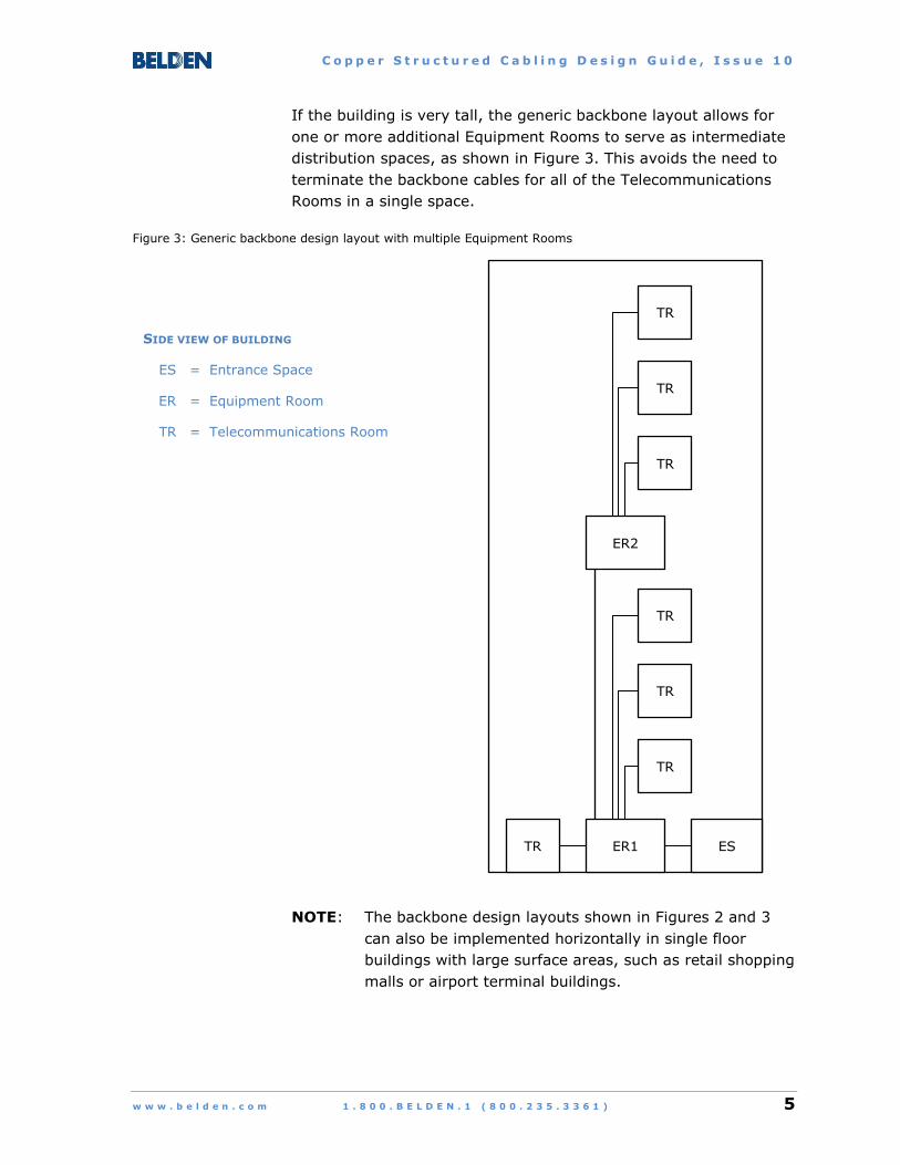
If the building is very tall, the generic backbone layout allows for
one or more additional Equipment Rooms to serve as intermediate
distribution spaces, as shown in Figure 3. This avoids the need to
terminate the backbone cables for all of the Telecommunications
Rooms in a single space.
Figure 3: Generic backbone design layout with multiple Equipment Rooms
NOTE: The backbone design layouts shown in Figures 2 and 3
can also be implemented horizontally in single floor
buildings with large surface areas, such as retail shopping
malls or airport terminal buildings.
ER1 ES
TR
TR
TR
TR
ER2
TR
TR
TR
SIDE VIEW OF BUILDING
ES = Entrance Space
ER = Equipment Room
TR = Telecommunications Room

C o p p e r S t r u c t u r e d C a b l i n g D e s i g n G u i d e , I s s u e 1 0
6 1 . 8 0 0 . B E L D E N . 1 ( 8 0 0 . 2 3 5 . 3 3 6 1 ) w w w . b e l d e n . c o m
Generic backbone design for a multi-building campus is an
extension of the single-building layout, with one building
designated as the Main Building for backbone cabling purposes.
Each of the other buildings on campus is a Satellite Building
directly connected to the Main Building, as shown in Figure 4.
Figure 4: Generic campus backbone design layout
Main Building
ES
Satellite Building 2
Satellite Building 3
ES
ES
Satellite Building 1
ES
TOP VIEW OF CAMPUS SITE
ES = Entrance Space
C o p p e r S t r u c t u r e d C a b l i n g D e s i g n G u i d e , I s s u e 1 0
w w w . b e l d e n . c o m 1 . 8 0 0 . B E L D E N . 1 ( 8 0 0 . 2 3 5 . 3 3 6 1 ) 7
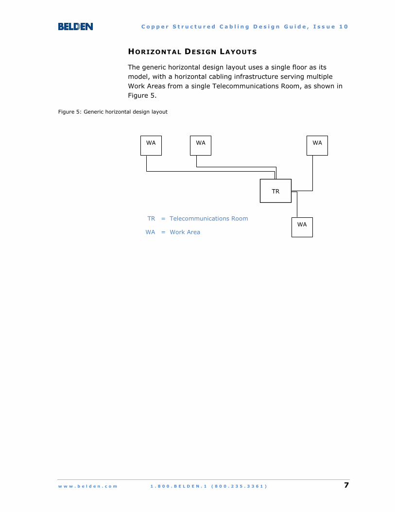
HORIZONTAL DESIGN LAYOUTS
The generic horizontal design layout uses a single floor as its
model, with a horizontal cabling infrastructure serving multiple
Work Areas from a single Telecommunications Room, as shown in
Figure 5.
Figure 5: Generic horizontal design layout
TR
WA WA WA
WA TR = Telecommunications Room
WA = Work Area

C o p p e r S t r u c t u r e d C a b l i n g D e s i g n G u i d e , I s s u e 1 0
8 1 . 8 0 0 . B E L D E N . 1 ( 8 0 0 . 2 3 5 . 3 3 6 1 ) w w w . b e l d e n . c o m
Telecommunications Enclosure
In cases where a portion of the floor area requires additional space
for telecommunications components, one or more smaller versions
of the Telecommunications Room called the Telecommunications
Enclosure can be added to the design layout, as shown in Figure 6.
Figure 6: Horizontal design layout with Telecommunications Enclosure
NOTE: The Telecommunications Enclosure is an optional addition
to—not a replacement for—the Telecommunications
Room.
TR
TE
Backbone cable from ER to TR Backbone cable from ER to TE (may be routed here through the TR)
ER = Equipment Room
TE = Telecommunications Enclosure
TR = Telecommunications Room

C o p p e r S t r u c t u r e d C a b l i n g D e s i g n G u i d e , I s s u e 1 0
w w w . b e l d e n . c o m 1 . 8 0 0 . B E L D E N . 1 ( 8 0 0 . 2 3 5 . 3 3 6 1 ) 9
Consolidation Point
Another option for the generic horizontal design layout is the
Consolidation Point, which allows for additional flexibility when
cabling runs need to be replaced (e.g., due to modular furniture
configuration changes in an office).
The Consolidation Point serves as an additional connector between
the Telecommunications Room or Telecommunications Enclosure
and the Work Area outlet in the modular furniture.
When the furniture needs to be moved, only the cable from the
outlet to the Consolidation Point has to be replaced—the cable from
the Consolidation Point to the Telecommunications Room or
Telecommunications Enclosure can remain undisturbed, as shown
in Figure 7.
Figure 7: Horizontal design layout with Consolidation Point
TR or TE
CP
CP = Consolidation Point
TE = Telecommunications Enclosure
TR = Telecommunications Room
WA = Work Area
WA
WA
WA

C o p p e r S t r u c t u r e d C a b l i n g D e s i g n G u i d e , I s s u e 1 0
10 1 . 8 0 0 . B E L D E N . 1 ( 8 0 0 . 2 3 5 . 3 3 6 1 ) w w w . b e l d e n . c o m
Multi-User Telecommunications Outlet Assembly
The Work Area connector serving the space assigned to a single
individual within a commercial building is commonly referred to as
a Telecommunications Outlet.
In spaces designed for multiple users (e.g., meeting or training
rooms) a larger version of the Telecommunications Outlet called a
Multi-User Telecommunications Outlet Assembly can be used in
place of multiple separate Telecommunications Outlets, as shown
in Figure 8.
Figure 8: Horizontal design layout with MUTOA
TR or TE
TO in individual WA
CP
TO in individual WA
TO in individual WA
CP
MUTOA in shared WA
Cords to devices in shared WA
CP = Consolidation Point
MUTOA = Multi-User Telecommunications
Outlet Assembly
TE = Telecommunications Enclosure
TO = Telecommunications Outlet
TR = Telecommunications Room
WA = Work Area

C o p p e r S t r u c t u r e d C a b l i n g D e s i g n G u i d e , I s s u e 1 0
w w w . b e l d e n . c o m 1 . 8 0 0 . B E L D E N . 1 ( 8 0 0 . 2 3 5 . 3 3 6 1 ) 11
3. PLANNING CONSIDERATIONS
CABLING SYSTEM PERFORMANCE
The performance requirements for a cabling system are directly
linked to the maximum network data rate expected over the
planned life of the installation.
Data rates for Ethernet networks are typically used for reference
due to the near-universal adoption of Ethernet as the networking
technology of choice.
Table 1 lists the performance categories for copper cabling
systems, their maximum Ethernet data rates, and the
corresponding maximum allowable end-to-end channel lengths.
Table 1: Copper cabling performance categories
Category Maximum Ethernet
Data Rate
Maximum Channel
Length
5e 1000 Mb/s (1 Gb/s) 100 m (328 ft)
6 1000 Mb/s (1 Gb/s) 100 m (328 ft)
10 Gb/s 37 m – 55 m
(121 ft – 180 ft)*
6A 10 Gb/s 100 m (328 ft)
8 (under development) 40 Gb/s 30 m (98 ft)
* This range is an estimated value that must be verified through field testing of each Category 6 cabling
run intended to support a 10 Gb/s data rate.
C o p p e r S t r u c t u r e d C a b l i n g D e s i g n G u i d e , I s s u e 1 0
12 1 . 8 0 0 . B E L D E N . 1 ( 8 0 0 . 2 3 5 . 3 3 6 1 ) w w w . b e l d e n . c o m
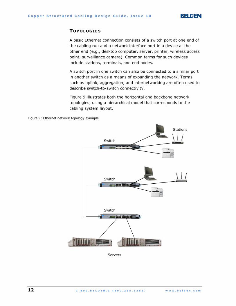
TOPOLOGIES
A basic Ethernet connection consists of a switch port at one end of
the cabling run and a network interface port in a device at the
other end (e.g., desktop computer, server, printer, wireless access
point, surveillance camera). Common terms for such devices
include stations, terminals, and end nodes.
A switch port in one switch can also be connected to a similar port
in another switch as a means of expanding the network. Terms
such as uplink, aggregation, and internetworking are often used to
describe switch-to-switch connectivity.
Figure 9 illustrates both the horizontal and backbone network
topologies, using a hierarchical model that corresponds to the
cabling system layout.
Figure 9: Ethernet network topology example
Servers
Switch
Stations
Switch
Switch

C o p p e r S t r u c t u r e d C a b l i n g D e s i g n G u i d e , I s s u e 1 0
w w w . b e l d e n . c o m 1 . 8 0 0 . B E L D E N . 1 ( 8 0 0 . 2 3 5 . 3 3 6 1 ) 13
Two-Connector Topology Using an Interconnect
The basic end-to-end cabling design layout uses two connectors
between the ports at either end of the link, as shown in Figure 10.
Figure 10: Two-connector topology using an interconnect
NOTE 1: A single set of connectors used to link cables directly to
equipment cords is referred to as an interconnect
configuration.
NOTE 2: The combined maximum length of the Work Area cord
PLUS the equipment cord is 10 m (33 ft).
Switch
Maximum 90 m (295 ft)
Patch panel Telecommunications
Outlet
Maximum 100 m (328 ft)
Work Area cord
Equipment cord

C o p p e r S t r u c t u r e d C a b l i n g D e s i g n G u i d e , I s s u e 1 0
14 1 . 8 0 0 . B E L D E N . 1 ( 8 0 0 . 2 3 5 . 3 3 6 1 ) w w w . b e l d e n . c o m
Three-Connector Topology Using a Cross-Connect
Additional flexibility and security can be obtained by using separate
sets of connectors to terminate cables and equipment pigtails or
cords, referred to as a cross-connect configuration. This allows for
the permanent cabling and isolation of the switches, with each port
always accessible through its associated patch panel instead of
directly at the switch, as shown in Figure 11.
Figure 11: Three-connector topology using a cross-connect
NOTE 1: The equipment cords can be pigtails (cords with modular
plugs at one end) terminated like cables onto standard
connectors or patch cords (modular plugs at both ends)
connected to coupler-type connectors.
NOTE 2: The combined maximum length of the Work Area cord
PLUS the equipment pigtail or cord PLUS the cross-
connect patch cord is 10 m (33 ft).
Switch isolated in a locked cabinet
Maximum 90 m (295 ft)
Patch panels
Telecommunications Outlet
Maximum 100 m (328 ft)
Work Area cord
Equipment pigtail or cord
Patch cord
C o p p e r S t r u c t u r e d C a b l i n g D e s i g n G u i d e , I s s u e 1 0
w w w . b e l d e n . c o m 1 . 8 0 0 . B E L D E N . 1 ( 8 0 0 . 2 3 5 . 3 3 6 1 ) 15
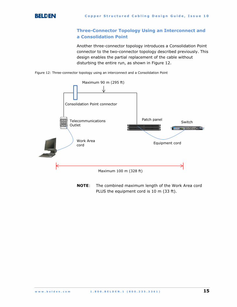
Three-Connector Topology Using an Interconnect and
a Consolidation Point
Another three-connector topology introduces a Consolidation Point
connector to the two-connector topology described previously. This
design enables the partial replacement of the cable without
disturbing the entire run, as shown in Figure 12.
Figure 12: Three-connector topology using an interconnect and a Consolidation Point
NOTE: The combined maximum length of the Work Area cord
PLUS the equipment cord is 10 m (33 ft).
Maximum 90 m (295 ft)
Telecommunications Outlet
Maximum 100 m (328 ft)
Work Area cord
Consolidation Point connector
Switch Patch panel
Equipment cord

C o p p e r S t r u c t u r e d C a b l i n g D e s i g n G u i d e , I s s u e 1 0
16 1 . 8 0 0 . B E L D E N . 1 ( 8 0 0 . 2 3 5 . 3 3 6 1 ) w w w . b e l d e n . c o m
Four-Connector Topology Using a Cross-Connect and a
Consolidation Point
This design uses the maximum allowable number of connections
for an end-to-end cabling channel, which is four. Both the switch
side and the station side are given maximum flexibility with the
inclusion of a cross-connect and a Consolidation Point, as shown in
Figure 13.
Figure 13: Four-connector topology using a cross-connect and a Consolidation Point
NOTE: The combined maximum length of the Work Area cord
PLUS the equipment pigtail or cord PLUS the cross-
connect patch cord is 10 m (33 ft).
Maximum 90 m (295 ft)
Telecommunications Outlet
Maximum 100 m (328 ft)
Work Area cord
Consolidation Point connector
Switch isolated in a locked cabinet
Patch panels
Equipment pigtail or cord
Patch cord
C o p p e r S t r u c t u r e d C a b l i n g D e s i g n G u i d e , I s s u e 1 0
w w w . b e l d e n . c o m 1 . 8 0 0 . B E L D E N . 1 ( 8 0 0 . 2 3 5 . 3 3 6 1 ) 17
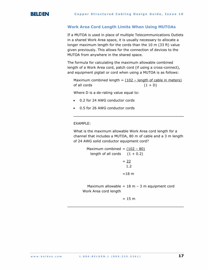
Work Area Cord Length Limits When Using MUTOAs
If a MUTOA is used in place of multiple Telecommunications Outlets
in a shared Work Area space, it is usually necessary to allocate a
longer maximum length for the cords than the 10 m (33 ft) value
given previously. This allows for the connection of devices to the
MUTOA from anywhere in the shared space.
The formula for calculating the maximum allowable combined
length of a Work Area cord, patch cord (if using a cross-connect),
and equipment pigtail or cord when using a MUTOA is as follows:
Maximum combined length = (102 – length of cable in meters)
of all cords (1 + D)
Where D is a de-rating value equal to:
0.2 for 24 AWG conductor cords
0.5 for 26 AWG conductor cords
EXAMPLE:
What is the maximum allowable Work Area cord length for a
channel that includes a MUTOA, 80 m of cable and a 3 m length
of 24 AWG solid conductor equipment cord?
Maximum combined = (102 – 80)
length of all cords (1 + 0.2)
= 22
1.2
=18 m
Maximum allowable = 18 m – 3 m equipment cord
Work Area cord length
= 15 m
C o p p e r S t r u c t u r e d C a b l i n g D e s i g n G u i d e , I s s u e 1 0
18 1 . 8 0 0 . B E L D E N . 1 ( 8 0 0 . 2 3 5 . 3 3 6 1 ) w w w . b e l d e n . c o m
SEPARATION FROM POWER CABLES AND
FLUORESCENT LIGHTING
Electrical codes typically specify minimum safety-related separation
distances for power cables, whether they are exposed, within
raceways, or terminated within shared spaces such as rooms or
outlet boxes.
Telecommunications standards also specify minimum separation
distances between network and power cables to minimize the risk
of electromagnetic interference (EMI) causing signal degradation or
loss.
ANSI/TIA-569-C titled “Commercial Building Standard for
Telecommunications Pathways and Spaces” contains minimum
separation recommendations for office cabling with values that
vary according to:
The number of power cables nearby
Their voltage and current ratings
Whether the circuits are single-phase or three-phase
Whether the individual power conductors in a circuit are loose
(i.e., exposed) or grouped together and covered with a jacket
Whether jacketed power cables contain any metallic armoring
or shielding elements
If a continuous metallic pathway completely covering the cables
(e.g., conduit) is used for either network cables or power cables,
there does not need to be a minimum separation between the two
types of cables.
Similarly, if power cables and network cables cross at a right angle
to each other, there does not need to be a minimum separation
apart from the need for a barrier to separate the network and
power cables in accordance with electrical code requirements.
If separate solid metallic or wire mesh cable trays are used for
both network and power cables, all minimum separation distances
listed can be reduced by 50 percent.
C o p p e r S t r u c t u r e d C a b l i n g D e s i g n G u i d e , I s s u e 1 0
w w w . b e l d e n . c o m 1 . 8 0 0 . B E L D E N . 1 ( 8 0 0 . 2 3 5 . 3 3 6 1 ) 19
For the following cases, the separation distance between network
and power cables is 600 mm (24 in) or more:
91 or more unscreened power cables, 120 or 230 volts,
20 amps, single-phase
29 or more unscreened power cables, 120 or 230 volts,
32 amps, single-phase
15 or more unscreened power cables, 120 or 230 volts,
63 amps, single-phase
4 or more unscreened power cables, 120 or 230 volts,
100 amps, single-phase
2 or more armored/screened or unscreened power cables, 480
volts, 100 amps, three-phase
NOTE: For other distances, refer to “Table 6 – Recommended
separation from power cabling for balanced twisted-pair
cabling” in ANSI/TIA-569-C.
The minimum separation distance between network cables and
fluorescent lighting such as lamps and fixtures is 125 mm (5 in).
C o p p e r S t r u c t u r e d C a b l i n g D e s i g n G u i d e , I s s u e 1 0
20 1 . 8 0 0 . B E L D E N . 1 ( 8 0 0 . 2 3 5 . 3 3 6 1 ) w w w . b e l d e n . c o m
TEMPERATURE AND HUMIDITY REQUIREMENTS
Telecommunications spaces within commercial buildings must
provide environmental conditions suitable for the continuous
operation of network equipment.
ANSI/TIA-569-C, titled “Commercial Building Standard for
Telecommunications Pathways and Spaces” and its Addendum 1,
titled “Revised Temperature and Humidity Requirements for
Telecommunications Spaces” specify the allowable values for
temperature, relative humidity, and dew point.
Telecommunications spaces within commercial buildings that are
covered by these publications include:
Entrance Spaces
Access or Service Provider Rooms/Spaces
Equipment Rooms
Telecommunications Rooms and Telecommunications
Enclosures
These spaces are rated Class B environments (formerly, Class 3)
by the American Society of Heating, Refrigerating and Air-
conditioning Engineers or ASHRAE, which serves as the source1 for
the environmental specifications referenced by ANSI/TIA-569-C
and its Addendum 1.
The specified values are as follows:
Allowable temperature range (dry bulb):
5 °C – 35 °C (41 °F – 95 °F)
Allowable relative humidity (RH) range:
8% – 80%
Maximum allowable dew point:
28 °C (82 °F)
Note that equipment manufacturers may specify limits that are
more restrictive or less restrictive than the values shown here.
1 ASHRAE “Thermal Guideline for Data Processing Environments”, 3rd Edition (2012)

C o p p e r S t r u c t u r e d C a b l i n g D e s i g n G u i d e , I s s u e 1 0
w w w . b e l d e n . c o m 1 . 8 0 0 . B E L D E N . 1 ( 8 0 0 . 2 3 5 . 3 3 6 1 ) 21
4. DESIGN GUIDELINES
This section features standards-based recommendations and
design options for copper structured cabling systems within the
following spaces in commercial buildings:
Work Area
Consolidation Point
Telecommunications Room
Telecommunications Enclosure
Equipment Room
Entrance Space
Note that in many cases, optical fiber cabling is used for both
in-building and campus network backbones. Please refer to
Belden’s “Optical Fiber Structured Cabling Design Guide”, which
contains recommended design options for fiber-based connectivity.
WORK AREA
Work Areas serve individuals (e.g., private offices, cubicles) or
groups (e.g., meeting rooms, reception areas) on a floor.
Structured cabling components for Work Areas include
Telecommunications Outlets, Multi-User Telecommunications Outlet
Assemblies, and cords to connect Work Area devices such as
desktop phones and computers to the outlets.
NOTE: Telecommunications Outlets commonly consist of
separate faceplates or other types of housings that
contain multiple spaces for inserts such as twisted-pair
modular jacks, optical fiber adapters, or coaxial video
connectors.
C o p p e r S t r u c t u r e d C a b l i n g D e s i g n G u i d e , I s s u e 1 0
22 1 . 8 0 0 . B E L D E N . 1 ( 8 0 0 . 2 3 5 . 3 3 6 1 ) w w w . b e l d e n . c o m
Work Area Specifications
1. For copper cabling, a minimum of two 4-pair, 100-ohm,
unshielded or shielded twisted-pair cables shall be terminated
within an individual Work Area. The choices are Category 6A,
Category 6, or Category 5e in any combination.
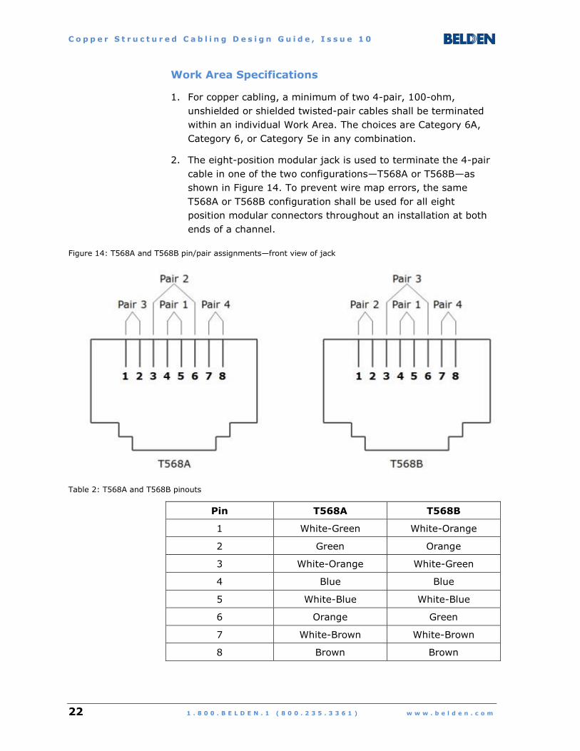
2. The eight-position modular jack is used to terminate the 4-pair
cable in one of the two configurations—T568A or T568B—as
shown in Figure 14. To prevent wire map errors, the same
T568A or T568B configuration shall be used for all eight
position modular connectors throughout an installation at both
ends of a channel.
Figure 14: T568A and T568B pin/pair assignments—front view of jack
Table 2: T568A and T568B pinouts
Pin T568A T568B
1 White-Green White-Orange
2 Green Orange
3 White-Orange White-Green
4 Blue Blue
5 White-Blue White-Blue
6 Orange Green
7 White-Brown White-Brown
8 Brown Brown

C o p p e r S t r u c t u r e d C a b l i n g D e s i g n G u i d e , I s s u e 1 0
w w w . b e l d e n . c o m 1 . 8 0 0 . B E L D E N . 1 ( 8 0 0 . 2 3 5 . 3 3 6 1 ) 23
3. If the Work Area device is equipped with a different type of
connector than the eight-position modular jack, any necessary
adapters must be installed external to the Telecommunications
Outlet (to avoid converting it into a device-specific connection
point).
4. For convenience, an electrical outlet should be available at the
same height and no farther than 1 m (3.3 ft) from the
Telecommunications Outlet.
5. A single Multi-User Telecommunications Outlet Assembly should
serve no more than 12 Work Areas.
6. A Multi-User Telecommunications Outlet Assembly contains no
active electronic equipment, only passive connectivity for
horizontal cabling runs.

C o p p e r S t r u c t u r e d C a b l i n g D e s i g n G u i d e , I s s u e 1 0
24 1 . 8 0 0 . B E L D E N . 1 ( 8 0 0 . 2 3 5 . 3 3 6 1 ) w w w . b e l d e n . c o m
Examples of Work Area Components
Telecommunications Outlets – Faceplates and Adapters
Figure 15: KeyConnect single-gang 2-port faceplate
Figure 16: KeyConnect stainless steel 4-port faceplate for institutional applications
C o p p e r S t r u c t u r e d C a b l i n g D e s i g n G u i d e , I s s u e 1 0
w w w . b e l d e n . c o m 1 . 8 0 0 . B E L D E N . 1 ( 8 0 0 . 2 3 5 . 3 3 6 1 ) 25
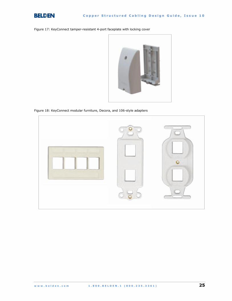
Figure 17: KeyConnect tamper-resistant 4-port faceplate with locking cover
Figure 18: KeyConnect modular furniture, Decora, and 106-style adapters
C o p p e r S t r u c t u r e d C a b l i n g D e s i g n G u i d e , I s s u e 1 0
26 1 . 8 0 0 . B E L D E N . 1 ( 8 0 0 . 2 3 5 . 3 3 6 1 ) w w w . b e l d e n . c o m
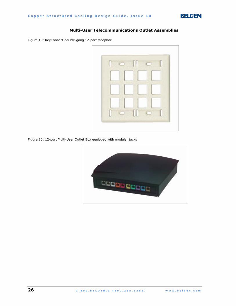
Multi-User Telecommunications Outlet Assemblies
Figure 19: KeyConnect double-gang 12-port faceplate
Figure 20: 12-port Multi-User Outlet Box equipped with modular jacks
C o p p e r S t r u c t u r e d C a b l i n g D e s i g n G u i d e , I s s u e 1 0
w w w . b e l d e n . c o m 1 . 8 0 0 . B E L D E N . 1 ( 8 0 0 . 2 3 5 . 3 3 6 1 ) 27
Telecommunications Outlets
Links to Additional Information:
Belden Copper Catalog (84 pages).pdf
Product Bulletin:
KeyConnect Workstation Outlet System (6 pages).pdf
Product pages at belden.com:
KeyConnect Faceplates
KeyConnect Adapters and Boxes
KeyConnect Tamper-Resistant Faceplates
General resource pages at belden.com:
Solutions Catalogs
Brochures
Product Bulletins
Installation Guides
C o p p e r S t r u c t u r e d C a b l i n g D e s i g n G u i d e , I s s u e 1 0
28 1 . 8 0 0 . B E L D E N . 1 ( 8 0 0 . 2 3 5 . 3 3 6 1 ) w w w . b e l d e n . c o m
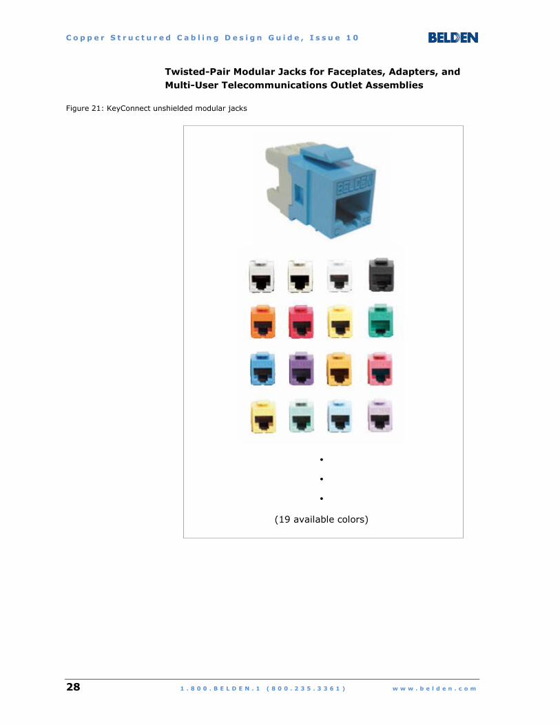
Twisted-Pair Modular Jacks for Faceplates, Adapters, and
Multi-User Telecommunications Outlet Assemblies
Figure 21: KeyConnect unshielded modular jacks
(19 available colors)

C o p p e r S t r u c t u r e d C a b l i n g D e s i g n G u i d e , I s s u e 1 0
w w w . b e l d e n . c o m 1 . 8 0 0 . B E L D E N . 1 ( 8 0 0 . 2 3 5 . 3 3 6 1 ) 29
Figure 22: KeyConnect shielded modular jacks
C o p p e r S t r u c t u r e d C a b l i n g D e s i g n G u i d e , I s s u e 1 0
30 1 . 8 0 0 . B E L D E N . 1 ( 8 0 0 . 2 3 5 . 3 3 6 1 ) w w w . b e l d e n . c o m
Modular Jacks
Links to Additional Information:
Belden Copper Catalog (84 pages).pdf
Product Bulletins:
KeyConnect Workstation Outlet System (6 pages).pdf
Shielded Cabling Systems (6 pages)
Product pages at belden.com:
Category 5E KeyConnect and MDVO-Style Modular Jacks
Category 6+ KeyConnect and MDVO-Style Modular Jacks
Category 6A 10GX KeyConnect and MDVO-Style Modular Jacks
Category 6+ Shielded Patch Panels and Modular Jacks
Category 6A 10GX Shielded System
General resource pages at belden.com:
Solutions Catalogs
Brochures
Product Bulletins
Installation Guides
C o p p e r S t r u c t u r e d C a b l i n g D e s i g n G u i d e , I s s u e 1 0
w w w . b e l d e n . c o m 1 . 8 0 0 . B E L D E N . 1 ( 8 0 0 . 2 3 5 . 3 3 6 1 ) 31
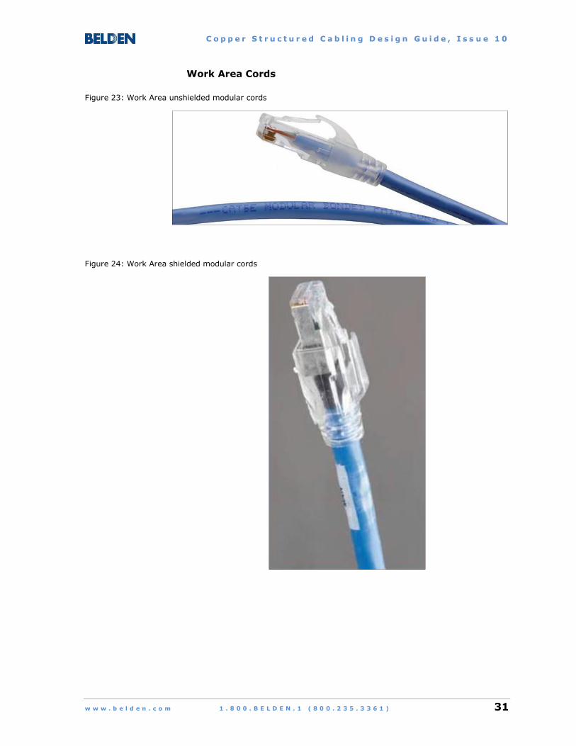
Work Area Cords
Figure 23: Work Area unshielded modular cords
Figure 24: Work Area shielded modular cords
C o p p e r S t r u c t u r e d C a b l i n g D e s i g n G u i d e , I s s u e 1 0
32 1 . 8 0 0 . B E L D E N . 1 ( 8 0 0 . 2 3 5 . 3 3 6 1 ) w w w . b e l d e n . c o m
Modular Cords
Links to Additional Information:
Belden Copper Catalog (84 pages).pdf
Product Bulletin:
10GX, CAT6+ and CAT5E Bonded-Pair Modular Cords (4 pages).pdf
Traceable Bonded-Pair Patch Cords (2 pages).pdf
Product pages at belden.com:
Category 5E Modular Cords
Category 6+ Modular Cords
Category 6A 10GX Modular Cords
Category 6+ Shielded Modular Cords
Category 6A 10GX Traceable Patch Cords
General resource pages at belden.com:
Solutions Catalogs
Brochures
Product Bulletins
Installation Guides
C o p p e r S t r u c t u r e d C a b l i n g D e s i g n G u i d e , I s s u e 1 0
w w w . b e l d e n . c o m 1 . 8 0 0 . B E L D E N . 1 ( 8 0 0 . 2 3 5 . 3 3 6 1 ) 33
CONSOLIDATION POINT (OPTIONAL)
A Consolidation Point serves as an optional interconnection in the
horizontal cable link between a Work Area outlet and its
corresponding Telecommunications Room or Telecommunications
Enclosure.
Consolidation Point Specifications
1. A cross-connect configuration is not permitted for the
connectors at the Consolidation Point.
2. Only one Consolidation Point connection is permitted within any
individual horizontal cable run. It should be located at least
15 m (49 ft) from the Telecommunications Room or
Telecommunications Enclosure to minimize the possibility of
signal degradation due to multiple connections within a short
distance.
3. A single Consolidation Point space should serve no more than
12 Work Areas.
4. A Consolidation Point contains no active electronic equipment,
only passive connectivity for horizontal cabling runs.
5. A Consolidation Point should be located in a permanent position
that is fully accessible (e.g., in an enclosure attached to a
building column, not to a moveable item of furniture).
6. Connections from a Consolidation Point directly into equipment
ports are not permitted. All cables from the Consolidation Point
shall terminate at Work Area outlets (Telecommunications
Outlets or Multi-User Telecommunications Outlet Assemblies) at
one end and connectors in Telecommunications Rooms or
Telecommunications Enclosures at the other end.
C o p p e r S t r u c t u r e d C a b l i n g D e s i g n G u i d e , I s s u e 1 0
34 1 . 8 0 0 . B E L D E N . 1 ( 8 0 0 . 2 3 5 . 3 3 6 1 ) w w w . b e l d e n . c o m
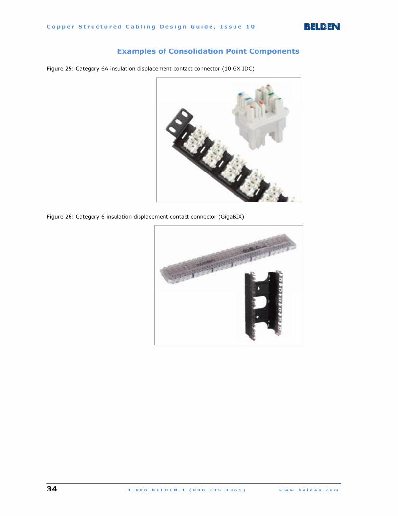
Examples of Consolidation Point Components
Figure 25: Category 6A insulation displacement contact connector (10 GX IDC)
Figure 26: Category 6 insulation displacement contact connector (GigaBIX)

C o p p e r S t r u c t u r e d C a b l i n g D e s i g n G u i d e , I s s u e 1 0
w w w . b e l d e n . c o m 1 . 8 0 0 . B E L D E N . 1 ( 8 0 0 . 2 3 5 . 3 3 6 1 ) 35
Figure 27: Category 5e insulation displacement contact connector (BIX)

C o p p e r S t r u c t u r e d C a b l i n g D e s i g n G u i d e , I s s u e 1 0
36 1 . 8 0 0 . B E L D E N . 1 ( 8 0 0 . 2 3 5 . 3 3 6 1 ) w w w . b e l d e n . c o m
Consolidation Point Components
Links to Additional Information:
Belden Copper Catalog (84 pages).pdf
Product pages at belden.com:
Category 6+ GigaBIX IDC System
Category 6A 10GX IDC System
General resource pages at belden.com:
Solutions Catalogs
Brochures
Product Bulletins
Installation Guides

C o p p e r S t r u c t u r e d C a b l i n g D e s i g n G u i d e , I s s u e 1 0
w w w . b e l d e n . c o m 1 . 8 0 0 . B E L D E N . 1 ( 8 0 0 . 2 3 5 . 3 3 6 1 ) 37
TELECOMMUNICATIONS ROOM
A Telecommunications Room serves as the floor-based centralized
distribution and management space for horizontal cables going to
Work Areas on the same floor as well as backbone cables coming
from the building’s Equipment Room. It can also contain active
electronic equipment such as network switches.
Telecommunications Room Specifications
1. The Telecommunications Room must be located as centrally as
possible to the area it serves.
2. The space allocated to the Telecommunications Room function
must be dedicated to that function—no other systems,
pathways, or components can be installed in or pass through
that space.
3. If multiple Telecommunications Rooms are required on the
same floor, they should be connected with a pathway consisting
of (or equivalent to) a Trade Size 3 (metric 78) conduit.
4. The minimum size of the Telecommunications Room is
3 m x 3 m (10 ft x 10 ft). A larger room may be required,
depending on the number of outlets served from that room, as
shown in Table 3.
Table 3: Telecommunications Room sizing
Number of Outlets
Served
Minimum Floor Space*
sq. m / sq. ft
Typical Dimensions*
m / ft
Up to 200 15 / 150 3 x 5 / 10 x 15
201 – 800 36 / 400 6 x 6 / 20 x 20
801 – 1600 72 / 800 6 x 12 / 20 x 40
1601 – 2400 108 / 1200 9 x 12 / 30 x 40
* Conversions are approximate

C o p p e r S t r u c t u r e d C a b l i n g D e s i g n G u i d e , I s s u e 1 0
38 1 . 8 0 0 . B E L D E N . 1 ( 8 0 0 . 2 3 5 . 3 3 6 1 ) w w w . b e l d e n . c o m
5. An environmental system capable of continuously monitoring
and maintaining temperature and humidity levels must be
available for the Telecommunications Room. If possible, the air
in the room should always remain at positive pressure with
respect to air in the surrounding space.
6. The power infrastructure for the Telecommunications Room
should include a dedicated electrical panel and the means to
automatically connect to a backup power source upon failure of
the primary supply.
7. A minimum of two 120 volt / 20 amp branch circuits must be
available for network equipment powering in the
Telecommunications Room. Each circuit shall terminate in a
dedicated duplex electrical outlet.
Additional duplex outlets on one or more separate branch
circuits for powering miscellaneous (i.e., non-network
equipment) devices must be located 150 mm (6 in) above the
floor, 1.8 m (6 ft) apart along all perimeter walls.
8. The horizontal cables going to Work Areas and backbone cables
coming from Equipment Rooms may be routed to and
terminated on any combination of:
Wall-mounted panels, racks, or enclosures
Free-standing open racks or enclosed cabinets
C o p p e r S t r u c t u r e d C a b l i n g D e s i g n G u i d e , I s s u e 1 0
w w w . b e l d e n . c o m 1 . 8 0 0 . B E L D E N . 1 ( 8 0 0 . 2 3 5 . 3 3 6 1 ) 39
TELECOMMUNICATIONS ENCLOSURE (OPTIONAL)
A Telecommunications Enclosure serves as an optional secondary
floor-based centralized management and distribution space for
horizontal cables routed to Work Areas on the same floor as well as
backbone cables coming from the building’s Equipment Room. It
can also contain active electronic equipment such as network
switches.
Telecommunications Enclosure Specifications
1. A Telecommunications Enclosure cannot be used in place of a
Telecommunications Room—each floor must have at least one
Telecommunications Room and may optionally have one or
more Telecommunications Enclosures.
2. Telecommunications Enclosures are sized to accommodate
current and future requirements and can be configured to blend
in with the architectural design of their destinations. Due to
their smaller size, they can be located in places where it would
be impossible or impractical to construct a separate dedicated
room (e.g., building lobby or atrium spaces, historical
properties with restrictions on allowable renovations).
3. Sufficient space shall be provided within the enclosure to
ensure compliance with cable bend radius requirements and to
facilitate mounting of hardware.
4. The minimum environmental and power requirements for
Telecommunications Enclosures are the same as those for
Telecommunications Rooms, with the following exceptions:
A minimum of one (not two) 120 volt / 20 amp branch
circuit, terminated in a dedicated duplex electrical outlet,
must be available for network equipment powering in the
Telecommunications Enclosure.
One additional duplex outlet on a separate branch circuit
should also be provided for powering miscellaneous
(i.e., non-network equipment) devices.

C o p p e r S t r u c t u r e d C a b l i n g D e s i g n G u i d e , I s s u e 1 0
40 1 . 8 0 0 . B E L D E N . 1 ( 8 0 0 . 2 3 5 . 3 3 6 1 ) w w w . b e l d e n . c o m
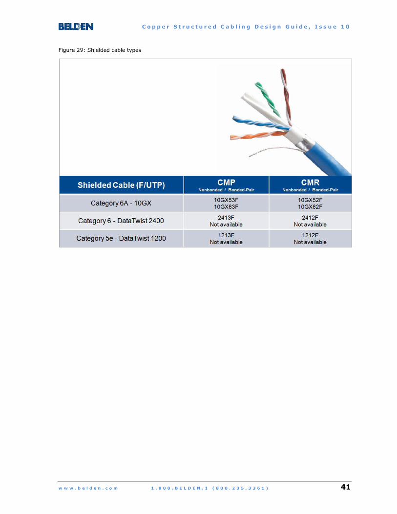
Examples of Telecommunications Room /
Telecommunications Enclosure Components
Horizontal Cables
Figure 28: Unshielded cable types
C o p p e r S t r u c t u r e d C a b l i n g D e s i g n G u i d e , I s s u e 1 0
w w w . b e l d e n . c o m 1 . 8 0 0 . B E L D E N . 1 ( 8 0 0 . 2 3 5 . 3 3 6 1 ) 41
Figure 29: Shielded cable types
C o p p e r S t r u c t u r e d C a b l i n g D e s i g n G u i d e , I s s u e 1 0
42 1 . 8 0 0 . B E L D E N . 1 ( 8 0 0 . 2 3 5 . 3 3 6 1 ) w w w . b e l d e n . c o m
Horizontal Cables
Links to Additional Information:
Belden Copper Catalog (84 pages).pdf
Product Bulletins:
Belden DataTwist 1200 Cables (4 pages).pdf
Belden DataTwist 2400 Cables (4 pages).pdf
Belden DataTwist 3600 Cables (6 pages).pdf
Belden 3600 Pre-Terminated Cabling System (8 pages).pdf
Belden DataTwist 4800 Cables (6 pages).pdf
Belden 10GX Cables (6 pages).pdf
Belden 10GX Pre-Terminated Cabling System (8 pages).pdf
Shielded Cabling Systems (6 pages).pdf
SFP+ Direct Attached Cables (2 pages).pdf
C o p p e r S t r u c t u r e d C a b l i n g D e s i g n G u i d e , I s s u e 1 0
w w w . b e l d e n . c o m 1 . 8 0 0 . B E L D E N . 1 ( 8 0 0 . 2 3 5 . 3 3 6 1 ) 43
Product pages at belden.com:
Category 5E DataTwist 1200 UTP Cable
Category 6+ DataTwist 2400 UTP Cable
Category 6+ DataTwist 3600 UTP Cable
Category 6+ DataTwist 4800 UTP Cable
Category 6A 10GX System Cable
Category 6A 10GX Pre-Terminated Cabling System
Category 6+ DataTwist 2400 Shielded Cable
Category 6A 10GX Shielded Cable
Category 6A 10GX Shielded Pre-Terminated System
Category 6A SFP+ Direct Attached Cables
General resource pages at belden.com:
Solutions Catalogs
Brochures
Product Bulletins
Installation Guides
C o p p e r S t r u c t u r e d C a b l i n g D e s i g n G u i d e , I s s u e 1 0
44 1 . 8 0 0 . B E L D E N . 1 ( 8 0 0 . 2 3 5 . 3 3 6 1 ) w w w . b e l d e n . c o m
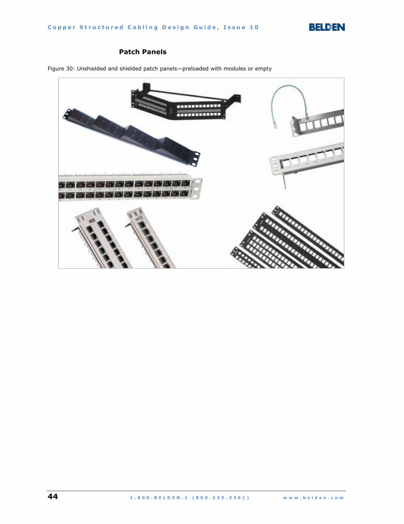
Patch Panels
Figure 30: Unshielded and shielded patch panels—preloaded with modules or empty

C o p p e r S t r u c t u r e d C a b l i n g D e s i g n G u i d e , I s s u e 1 0
w w w . b e l d e n . c o m 1 . 8 0 0 . B E L D E N . 1 ( 8 0 0 . 2 3 5 . 3 3 6 1 ) 45
Patch Panels
Links to Additional Information:
Belden Copper Catalog (84 pages).pdf
Product Bulletins:
KeyConnect Patch Panels (2 pages).pdf
AngleFlex Patch Panels (2 pages).pdf
Product pages at belden.com:
Category 5E KeyConnect Patch Panels
Category 6+ KeyConnect Patch Panels
Category 6A 10GX Patch Panels
Category 6+ Shielded Patch Panels and Modular Jacks
Category 6A 10GX Shielded System
General resource pages at belden.com:
Solutions Catalogs
Brochures
Product Bulletins
Installation Guides

C o p p e r S t r u c t u r e d C a b l i n g D e s i g n G u i d e , I s s u e 1 0
46 1 . 8 0 0 . B E L D E N . 1 ( 8 0 0 . 2 3 5 . 3 3 6 1 ) w w w . b e l d e n . c o m
Racks and Enclosures
Figure 31: Wall-mount and free-standing racks and enclosures
C o p p e r S t r u c t u r e d C a b l i n g D e s i g n G u i d e , I s s u e 1 0
w w w . b e l d e n . c o m 1 . 8 0 0 . B E L D E N . 1 ( 8 0 0 . 2 3 5 . 3 3 6 1 ) 47
Racks and Enclosures
Links to Additional Information:
Belden Infrastructure Solutions Catalog (84 pages).pdf
Product Bulletins:
High-density Racking System (4 pages).pdf
Belden Performance Value Line (4 pages).pdf
Belden X Series Enclosures (4 pages).pdf
Adaptive Enclosure Heat Containment System (4 pages).pdf
Product pages at belden.com:
Infrastructure Solutions
Enclosures and Racks
Data Center Solutions Configurator
General resource pages at belden.com:
Solutions Catalogs
Brochures
Product Bulletins
Installation Guides

C o p p e r S t r u c t u r e d C a b l i n g D e s i g n G u i d e , I s s u e 1 0
48 1 . 8 0 0 . B E L D E N . 1 ( 8 0 0 . 2 3 5 . 3 3 6 1 ) w w w . b e l d e n . c o m
EQUIPMENT ROOM
A single Equipment Room serves as the building’s centralized
distribution and management space for backbone cables going to
the Telecommunications Rooms (and optionally, to the
Telecommunications Enclosures) on every floor in the building.
Other types of cables that may be terminated in the Equipment
Room include telecommunications circuits from access or service
providers and campus cabling to one or more other buildings on
the same site.
An Equipment Room can also contain active electronic equipment
serving multiple floors or the entire building, such as switches,
servers, routers, and mass storage units for a variety of
applications. These include:
Traditional data
Voice / telephony
Audio / video
Premises security (e.g., surveillance, access control)
Building management (e.g., lighting, climate control)
Equipment Room Specifications
1. The space serving as the Equipment Room for the building can
also contain a Telecommunications Room serving horizontal
cabling to the Work Areas located on the same floor as the
Equipment Room.
2. To facilitate in-building backbone cabling runs, the Equipment
Room should be vertically aligned with the Telecommunications
Rooms on all of the other floors in the building.
3. The minimum sizing, environmental, and power requirements
for Equipment Rooms are the same as those for
Telecommunications Rooms, with the acknowledgement that an
Equipment Room is usually a larger space. In buildings with
high pair-count copper backbone cabling (e.g., 300 or more
pairs to every floor in a 20-floor building), it may be necessary
to use special-purpose free-standing frame systems in the
Equipment Room in order to efficiently terminate and manage
the large number of connections.
C o p p e r S t r u c t u r e d C a b l i n g D e s i g n G u i d e , I s s u e 1 0
w w w . b e l d e n . c o m 1 . 8 0 0 . B E L D E N . 1 ( 8 0 0 . 2 3 5 . 3 3 6 1 ) 49
Examples of Equipment Room Components
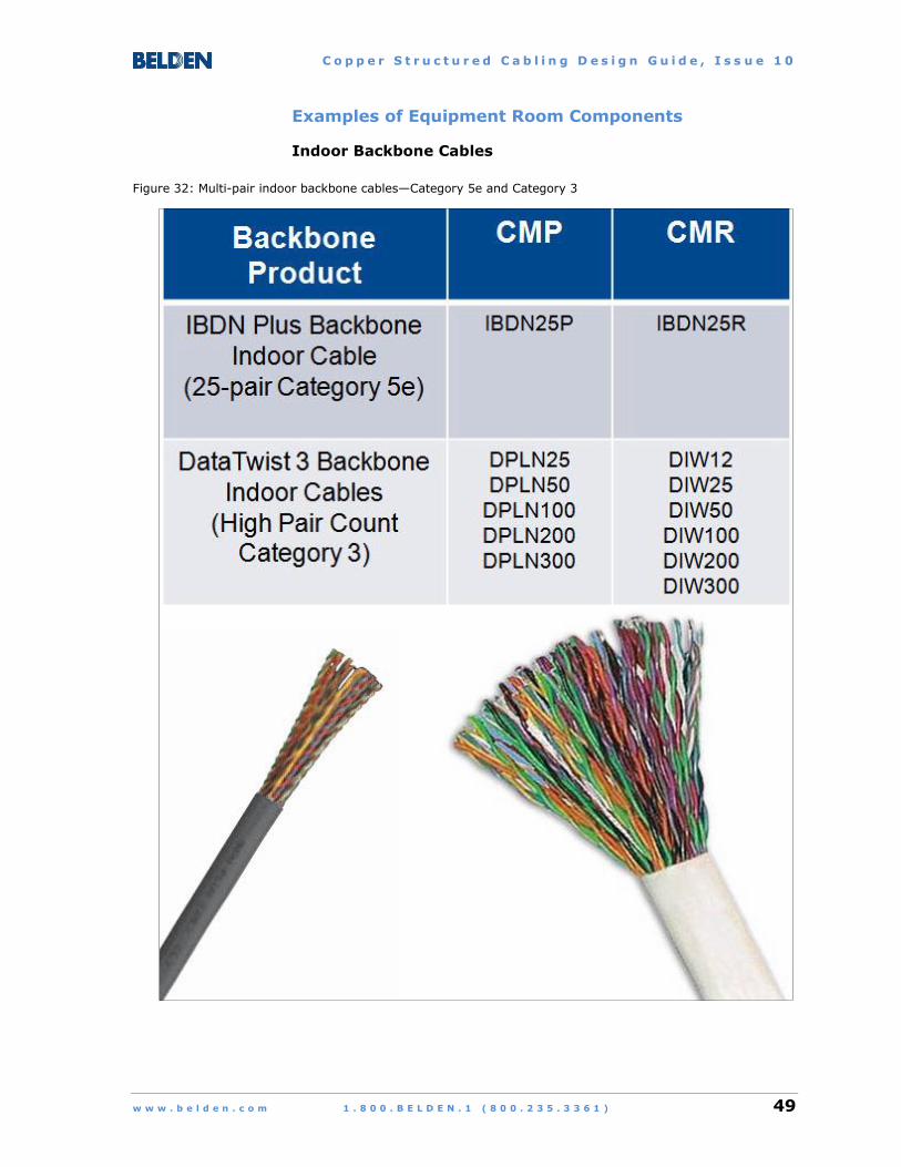
Indoor Backbone Cables
Figure 32: Multi-pair indoor backbone cables—Category 5e and Category 3

C o p p e r S t r u c t u r e d C a b l i n g D e s i g n G u i d e , I s s u e 1 0
50 1 . 8 0 0 . B E L D E N . 1 ( 8 0 0 . 2 3 5 . 3 3 6 1 ) w w w . b e l d e n . c o m
Indoor Backbone Cables
Links to Additional Information:
Belden Copper Catalog (84 pages).pdf
General resource pages at belden.com:
Solutions Catalogs
Brochures
Product Bulletins
Installation Guides
C o p p e r S t r u c t u r e d C a b l i n g D e s i g n G u i d e , I s s u e 1 0
w w w . b e l d e n . c o m 1 . 8 0 0 . B E L D E N . 1 ( 8 0 0 . 2 3 5 . 3 3 6 1 ) 51
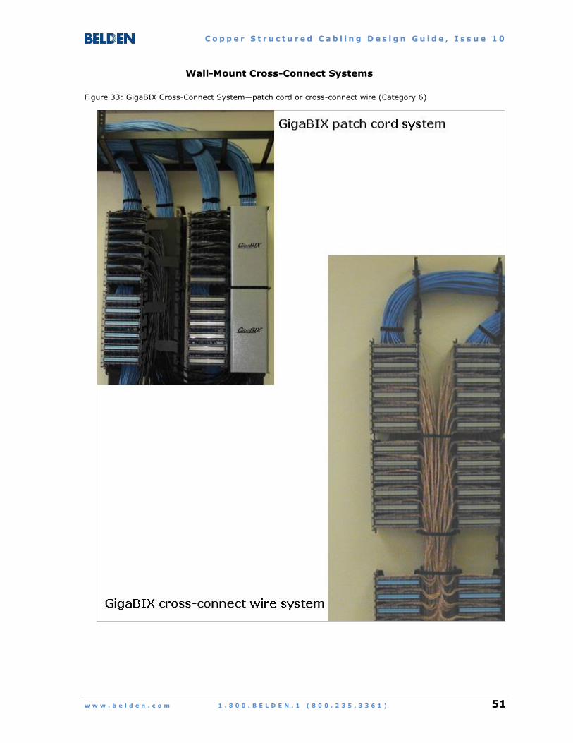
Wall-Mount Cross-Connect Systems
Figure 33: GigaBIX Cross-Connect System—patch cord or cross-connect wire (Category 6)

C o p p e r S t r u c t u r e d C a b l i n g D e s i g n G u i d e , I s s u e 1 0
52 1 . 8 0 0 . B E L D E N . 1 ( 8 0 0 . 2 3 5 . 3 3 6 1 ) w w w . b e l d e n . c o m
Figure 34: BIX Cross-Connect System—patch cord or cross-connect wire (Category 5e)
Figure 35: 110- Cross-Connect System—patch cord (Category 5e)

C o p p e r S t r u c t u r e d C a b l i n g D e s i g n G u i d e , I s s u e 1 0
w w w . b e l d e n . c o m 1 . 8 0 0 . B E L D E N . 1 ( 8 0 0 . 2 3 5 . 3 3 6 1 ) 53
Wall-Mount Cross-Connect Systems
Links to Additional Information:
Belden Copper Catalog (84 pages).pdf
General resource pages at belden.com:
Solutions Catalogs
Brochures
Product Bulletins
Installation Guides
C o p p e r S t r u c t u r e d C a b l i n g D e s i g n G u i d e , I s s u e 1 0
54 1 . 8 0 0 . B E L D E N . 1 ( 8 0 0 . 2 3 5 . 3 3 6 1 ) w w w . b e l d e n . c o m
ENTRANCE SPACE
Once an outdoor-rated cable physically enters a building through
an entrance point in an exterior wall, it is subject to the same
requirements (e.g., fire resistance) as in-building cable. In most
cases, this requires a transition from one cable type to another,
using either splicing or connectorization.
If the cable contains both copper conductors and other metallic
elements (e.g., shielding, armor), it is mandatory to provide
electrical protection and to bond the shield or armor to the
grounding system for life safety and the protection of property.
In the case of cable delivering telecommunications circuits from
access or service providers, an additional physical demarcation
point is required to identify the boundary between the provider and
the building owner or tenant. Any time there is a problem with a
circuit, the provider can test in the direction facing outwards from
the demarcation point and the building owner or tenant can test in
the direction facing inwards.
Entrance Space Specifications
1. All entrance services (i.e., transition, electrical protection,
grounding, demarcation) can be provided in one or more stand-
alone Entrance Spaces or a dedicated Entrance Space within
the building’s Equipment Room. If the useable floor space in
the building exceeds 2000 sq. m (21,520 sq. ft), it is
recommended to provide a separate enclosed Entrance Space.
2. An Entrance Space can also contain network equipment
belonging to the building owner, a tenant, or a
telecommunications circuit provider.
3. Entrance services should be as close as possible to both the
cable entrance point and the building’s main electrical
distribution panel (in order to minimize the length of the
bonding conductors from the cables to the grounding system).
4. The minimum environmental and power requirements for
Entrance Spaces are the same as those for Telecommunications
Rooms.

C o p p e r S t r u c t u r e d C a b l i n g D e s i g n G u i d e , I s s u e 1 0
w w w . b e l d e n . c o m 1 . 8 0 0 . B E L D E N . 1 ( 8 0 0 . 2 3 5 . 3 3 6 1 ) 55
Example of Entrance Space Components
Figure 36: 4-pair gel-filled outside plant cables—Category 6 and Category 5e

C o p p e r S t r u c t u r e d C a b l i n g D e s i g n G u i d e , I s s u e 1 0
56 1 . 8 0 0 . B E L D E N . 1 ( 8 0 0 . 2 3 5 . 3 3 6 1 ) w w w . b e l d e n . c o m
Entrance Space Components
Links to Additional Information:
Belden Copper Catalog (84 pages).pdf
General resource pages at belden.com:
Solutions Catalogs
Brochures
Product Bulletins
Installation Guides
C o p p e r S t r u c t u r e d C a b l i n g D e s i g n G u i d e , I s s u e 1 0
w w w . b e l d e n . c o m 1 . 8 0 0 . B E L D E N . 1 ( 8 0 0 . 2 3 5 . 3 3 6 1 ) 57
5. INSTALLATION AND TESTING GUIDELINES
INTRODUCTION
Guidelines for the installation of copper cabling systems and
components are provided by standards, industry best practices,
and manufacturers. Their common goal is to prevent faulty
installation or poor maintenance of cables and connectors in order
to avoid costly network outages and time-consuming
troubleshooting.
Sources of installation guidelines include ANSI/TIA-568-C.0
(Generic Telecommunications Cabling for Customer Premises)
Section 5, titled "Cabling Installation Requirements" and BICSI's
Information Technology Systems Installation Methods Manual
(ITSIMM), 6th Edition.
The following are examples of copper cable termination
requirements, extracted from a published project specification
document:
Cables shall be installed and terminated in accordance with
standards-based requirements and recommendations
(e.g., TIA), industry best practices (e.g., BICSI Information
Technology Systems Installation Methods Manual), and Belden's
Installation Guides.
The twisted pairs shall be guided, positioned and secured at the
connector termination point using a bar mechanism that locks
the pairs in place to prevent the untwisting of pairs when
terminating the conductors.
Cables shall be neatly bundled, dressed, and routed to their
respective termination connectors. Each patch panel shall
terminate one or more cable bundles separated and dressed
back to the point of cable entrance into the equipment cabinet
or rack.
Each cable shall be clearly labeled on the cable jacket behind
the patch panel at a location that can be viewed without the
prior removal of any support element for the cable bundle.
C o p p e r S t r u c t u r e d C a b l i n g D e s i g n G u i d e , I s s u e 1 0
58 1 . 8 0 0 . B E L D E N . 1 ( 8 0 0 . 2 3 5 . 3 3 6 1 ) w w w . b e l d e n . c o m
Testing is an integral component of installation, maintenance, and
troubleshooting for both cabling systems and the network devices
they connect. When an active link fails, testing makes it possible to
isolate or eliminate the cables and connectors between the devices
as the source of the fault.
Three levels of testing are possible, as follows:
Basic verification
Testing to verify that the components in a cabling link are
properly connected and not damaged.
Network qualification
Testing to verify that the cabling link provides error-free signal
transport for a specific type of network (e.g., Gigabit or
10 Gigabit Ethernet).
Certification
Testing to verify that the cabling link passes all of the
requirements as published in an industry-recognized cabling
standard (e.g., ANSI/TIA-568-C, ISO/IEC 11801).
NOTE: Familiarity with the selected testing instruments and
associated software is essential for correct test setups
and subsequent interpretation of test results.
C o p p e r S t r u c t u r e d C a b l i n g D e s i g n G u i d e , I s s u e 1 0
w w w . b e l d e n . c o m 1 . 8 0 0 . B E L D E N . 1 ( 8 0 0 . 2 3 5 . 3 3 6 1 ) 59
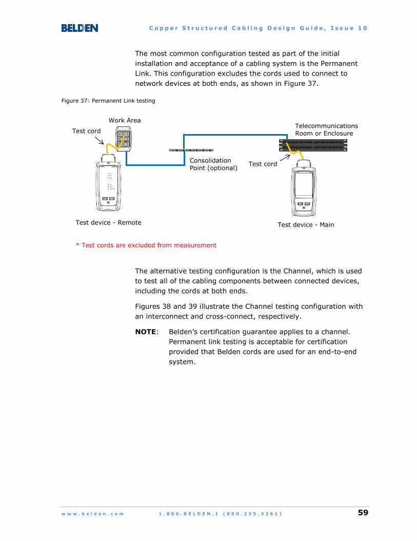
The most common configuration tested as part of the initial
installation and acceptance of a cabling system is the Permanent
Link. This configuration excludes the cords used to connect to
network devices at both ends, as shown in Figure 37.
Figure 37: Permanent Link testing
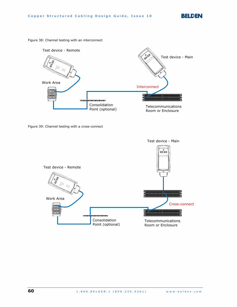
The alternative testing configuration is the Channel, which is used
to test all of the cabling components between connected devices,
including the cords at both ends.
Figures 38 and 39 illustrate the Channel testing configuration with
an interconnect and cross-connect, respectively.
NOTE: Belden’s certification guarantee applies to a channel.
Permanent link testing is acceptable for certification
provided that Belden cords are used for an end-to-end
system.
Test cord
Work Area
Consolidation Point (optional)
Telecommunications Room or Enclosure
Test device - Main Test device - Remote
* Test cords are excluded from measurement
Test cord
C o p p e r S t r u c t u r e d C a b l i n g D e s i g n G u i d e , I s s u e 1 0
60 1 . 8 0 0 . B E L D E N . 1 ( 8 0 0 . 2 3 5 . 3 3 6 1 ) w w w . b e l d e n . c o m
Figure 38: Channel testing with an interconnect
Figure 39: Channel testing with a cross-connect
Interconnect Work Area
Telecommunications Room or Enclosure
Consolidation
Point (optional)
Test device - Main
Test device - Remote
Cross-connect
Work Area
Telecommunications Room or Enclosure
Consolidation Point (optional)
Test device - Remote
Test device - Main

C o p p e r S t r u c t u r e d C a b l i n g D e s i g n G u i d e , I s s u e 1 0
w w w . b e l d e n . c o m 1 . 8 0 0 . B E L D E N . 1 ( 8 0 0 . 2 3 5 . 3 3 6 1 ) 61
There are 10 parameters that must be tested and reported in order
to comply with ANSI/TIA-1152, titled “Requirements for Field Test
Instruments and Measurements for Balanced Twisted-Pair Cabling”.
1. Wire map/shield continuity (when testing shielded cabling)
2. Length, using the shortest pair (with fewest twists per unit of
measure)
3. Propagation delay for each pair
4. Delay skew (delay between each of the three pairs and the
shortest/reference pair, at 10 MHz)
5. Insertion loss
6. Return loss—must test from both ends
7. Near-End Crosstalk (NEXT)—must test from both ends
8. Power-Sum Near-End Crosstalk (PSNEXT)—must test from both
ends
9. Attenuation-to-Crosstalk Ratio, Far end (ACRF)—must test from
both ends
10. Power-Sum Attenuation-to-Crosstalk Ratio, Far end (PSACRF)—
must test from both ends
C o p p e r S t r u c t u r e d C a b l i n g D e s i g n G u i d e , I s s u e 1 0
62 1 . 8 0 0 . B E L D E N . 1 ( 8 0 0 . 2 3 5 . 3 3 6 1 ) w w w . b e l d e n . c o m
EXTENT OF TESTING
The extent of testing shall be in accordance with the end-
customer’s testing requirements. Belden recommends 100%
testing of permanent links for Insertion Loss, Return Loss, NEXT,
PSNEXT, and PSACRF. These tests are performed at the same
time as the Continuity Test using an automated tester such as the
Fluke DTX-1800.
For Category 6A installations, a random sampling of short length
and long length installed permanent links shall be tested for Power-
Sum Alien Near-End Crosstalk (PSANEXT) and Power-Sum Alien
Attenuation-to-Crosstalk Ratio, Far-end (PSAACRF). The links
selected for testing shall follow the selection criteria specified in
ANSI/TIA-568-C.2, “Balanced Twisted-Pair Telecommunications
Cabling and Components Standard”.
With regards to the sampling size for alien crosstalk testing, the
Belden Certified System Vendor (CSV) shall test in accordance with
the end-customer’s testing/sampling requirements, or a minimum
of five (5) permanent links or 1% of installed permanent links—
whichever is greater—up to a maximum of thirty (30) permanent
links.
Links to Additional Information at belden.com:
Belden Installation Guides page
Belden LabelFlex Labeling System page
Belden Conduit Capacity Calculator page
Links to Additional Information at flukenetworks.com:
Fluke Networks - Learn About Cable Installation page
Fluke Networks - Learn About Cable Testing page

C o p p e r S t r u c t u r e d C a b l i n g D e s i g n G u i d e , I s s u e 1 0
w w w . b e l d e n . c o m 1 . 8 0 0 . B E L D E N . 1 ( 8 0 0 . 2 3 5 . 3 3 6 1 ) 63
ANNEX A: DESIGN EXAMPLES
IBDN UNSHIELDED CABLING SYSTEMS
The design examples in this Annex are intended to provide
guidance on product selection for Belden’s unshielded twisted-pair
structured cabling systems.
Three performance levels are featured:
Category 6A
Category 6
Category 5e

C o p p e r S t r u c t u r e d C a b l i n g D e s i g n G u i d e , I s s u e 1 0
64 1 . 8 0 0 . B E L D E N . 1 ( 8 0 0 . 2 3 5 . 3 3 6 1 ) w w w . b e l d e n . c o m
DESIGN EXAMPLE 1 — CATEGORY 6A
Customer Requirement:
Category 6A end-to-end performance to enable Ethernet
connections to any device at up to 10 Gb/s over a maximum
100 m (328 ft) channel length.
Category 6A bandwidth: 500 MHz
Belden IBDN 10GX System bandwidth: 625 MHz
Proposed Design:
Two-connector topology - Telecommunications Outlet
or Multi-User Telecommunications Outlet Assembly
in Work Area and interconnect patch panel layout in
Telecommunications Room
10GX Modular Cords (Bonded-pair, 24 AWG solid conductors)
KeyConnect, MediaFlex, Interface, or MDVO outlet hardware, equipped with
10GX Modular Jacks
10GX UTP Cable (Nonbonded-pair or bonded-pair, 23 AWG)
10GX Patch Panels (Empty or preloaded with 10GX Modular Jacks)
To Work Area device port
2
To Switch port
Maximum 100 m (328 ft)
1 1
3 4

C o p p e r S t r u c t u r e d C a b l i n g D e s i g n G u i d e , I s s u e 1 0
w w w . b e l d e n . c o m 1 . 8 0 0 . B E L D E N . 1 ( 8 0 0 . 2 3 5 . 3 3 6 1 ) 65
DESIGN EXAMPLE 2 — CATEGORY 6
Customer Requirement:
Category 6 end-to-end performance to enable Ethernet connections
to any device at up to 1 Gb/s over a maximum of 100 m (328 ft)
channel length. Some of the shorter channels—up to any length
between 37 m (121 ft) and 55 m (180 ft) depending on bundling
conditions—may be used for 10 Gb/s connections after successful
field testing for qualification.
Category 6 bandwidth: 200 MHz, with transmission
characteristics specified to 250 MHz.
Belden IBDN 4800 System bandwidth: 300 MHz
Belden IBDN 3600 System bandwidth: 280 MHz
Belden IBDN 2400 System bandwidth: 250 MHz
NOTE: Although each of these three IBDN Systems features one
or more cables with unique characteristics, they all use
the same connectors and cords.
Proposed Design:
Three-connector topology - Telecommunications Outlet
or Multi-User Telecommunications Outlet Assembly
in Work Area and cross-connect patch panel layout in
Telecommunications Room

C o p p e r S t r u c t u r e d C a b l i n g D e s i g n G u i d e , I s s u e 1 0
66 1 . 8 0 0 . B E L D E N . 1 ( 8 0 0 . 2 3 5 . 3 3 6 1 ) w w w . b e l d e n . c o m
CAT6+ Modular Cords, (Bonded-pair, 24 AWG solid conductors)
KeyConnect, MediaFlex, Interface, or MDVO outlet hardware, equipped with
CAT6+ Modular Jacks
DataTwist 4800 UTP Cable (Nonbonded-pair or bonded-pair, 23 AWG) … or
DataTwist 3600 UTP Cable (Nonbonded-pair or bonded-pair, 23 AWG) … or
DataTwist 2400 UTP Cable (Nonbonded-pair or bonded-pair, 23 AWG)
CAT6+ Patch Panels (Empty or preloaded with CAT6+ Modular Jacks) … or
Belden IBDN GigaBIX Cross-Connect System
CAT6+ Pigtails (Nonbonded-pair, 23 AWG solid conductors)
To Work Area device port
2
To Switch port
Maximum 100 m (328 ft)
1
3 4
4
1
5

C o p p e r S t r u c t u r e d C a b l i n g D e s i g n G u i d e , I s s u e 1 0
w w w . b e l d e n . c o m 1 . 8 0 0 . B E L D E N . 1 ( 8 0 0 . 2 3 5 . 3 3 6 1 ) 67
DESIGN EXAMPLE 3 — CATEGORY 5E
Customer Requirement:
Category 5e end-to-end performance to enable Ethernet
connections to any device at up to 1 Gb/s over a maximum
100 m (328 ft) channel length.
Category 5e bandwidth: 100 MHz
Belden IBDN 1200 System bandwidth: 160 MHz
Proposed Design:
Four-connector topology - Telecommunications Outlet
or Multi-User Telecommunications Outlet Assembly in
Work Area, Consolidation Point, and cross-connect patch
panel layout in Telecommunications Room

C o p p e r S t r u c t u r e d C a b l i n g D e s i g n G u i d e , I s s u e 1 0
68 1 . 8 0 0 . B E L D E N . 1 ( 8 0 0 . 2 3 5 . 3 3 6 1 ) w w w . b e l d e n . c o m
CAT5E Modular Cords (Bonded-pair, 24 AWG solid conductors)
KeyConnect, MediaFlex, Interface, or MDVO outlet hardware, equipped with
CAT5E Modular Jacks
BIX connectors or CAT5E Modular Jacks and outlet hardware
DataTwist 1200 UTP Cable (Bonded-pair, 24 AWG) … or
CAT5E Pigtails (Nonbonded-pair, 24 AWG solid conductors)
NOTE: If modular jacks are used in place of BIX connectors, pigtails must
be used in place of horizontal cable.
DataTwist 1200 UTP Cable (Bonded-pair, 24 AWG)
CAT5E Patch Panels (Empty or preloaded with CAT5E Modular Jacks) … or
Belden IBDN BIX Cross-Connect System … or
Belden 110 Cross-Connect System
CAT5E Pigtails (Nonbonded-pair, 24 AWG solid conductors)
To Work Area device port
2
To Switch port
Maximum 100 m (328 ft)
1 4
3
6
1
5
6
7
or
C o p p e r S t r u c t u r e d C a b l i n g D e s i g n G u i d e , I s s u e 1 0
w w w . b e l d e n . c o m 1 . 8 0 0 . B E L D E N . 1 ( 8 0 0 . 2 3 5 . 3 3 6 1 ) 69
ANNEX B: DESIGN EXAMPLES
IBDN SHIELDED CABLING SYSTEMS
The design examples in this Annex are intended to provide
guidance on product selection for Belden’s shielded twisted-pair
structured cabling systems.
Three performance levels are featured:
Category 6A
Category 6
Category 5e

C o p p e r S t r u c t u r e d C a b l i n g D e s i g n G u i d e , I s s u e 1 0
70 1 . 8 0 0 . B E L D E N . 1 ( 8 0 0 . 2 3 5 . 3 3 6 1 ) w w w . b e l d e n . c o m
DESIGN EXAMPLE 1 — CATEGORY 6A
Customer Requirement:
Category 6A end-to-end performance to enable Ethernet
connections to any device at up to 10 Gb/s over a maximum
100 m (328 ft) channel length.
Category 6A bandwidth: 500 MHz
Belden IBDN 10GX Shielded System bandwidth: 625 MHz
Proposed Design:
Two-connector topology - Telecommunications Outlet
or Multi-User Telecommunications Outlet Assembly
in Work Area and interconnect patch panel layout in
Telecommunications Room
10GX Shielded Modular Cords (Bonded-pair, 24 AWG solid conductors)
KeyConnect or MediaFlex outlet hardware, equipped with
10GX Shielded Modular Jacks
10GX Shielded Cable (F/UTP, nonbonded-pair or bonded-pair, 23 AWG)
10GX Shielded Patch Panels (Empty) and 10GX Shielded Modular Jacks
To Work Area device port
2
To Switch port
Maximum 100 m (328 ft)
1 1
3 4
C o p p e r S t r u c t u r e d C a b l i n g D e s i g n G u i d e , I s s u e 1 0
w w w . b e l d e n . c o m 1 . 8 0 0 . B E L D E N . 1 ( 8 0 0 . 2 3 5 . 3 3 6 1 ) 71
DESIGN EXAMPLE 2 — CATEGORY 6
Customer Requirement:
Category 6 end-to-end performance to enable Ethernet connections
to any device at up to 1 Gb/s over a maximum of 100 m (328 ft)
channel length. Some of the shorter channels—up to 55 (180 ft) in
length—may be used for 10 Gb/s connections after successful field
testing for qualification.
Category 6 bandwidth: 200 MHz, with transmission
characteristics specified to 250 MHz.
Belden IBDN 2400 Shielded System bandwidth: 250 MHz
Proposed Design:
Three-connector topology - Telecommunications Outlet
or Multi-User Telecommunications Outlet Assembly
in Work Area and cross-connect patch panel layout in
Telecommunications Room

C o p p e r S t r u c t u r e d C a b l i n g D e s i g n G u i d e , I s s u e 1 0
72 1 . 8 0 0 . B E L D E N . 1 ( 8 0 0 . 2 3 5 . 3 3 6 1 ) w w w . b e l d e n . c o m
CAT6+ Shielded Modular Cords, (Nonbonded-pair, 24 AWG solid conductors)
KeyConnect or MediaFlex outlet hardware, equipped with CAT6+ Shielded
KeyConnect Modular Jacks
DataTwist 2400 Shielded Cable (Nonbonded-pair, 23 AWG)
CAT6+ Shielded Patch Panels (Empty) and CAT6+ Shielded KeyConnect
Modular Jacks
CAT6+ Shielded Pigtails (Nonbonded-pair, 24 AWG solid conductors)
To Work Area device port
2
To Switch port
Maximum 100 m (328 ft)
1
3 4
4
1
5

C o p p e r S t r u c t u r e d C a b l i n g D e s i g n G u i d e , I s s u e 1 0
w w w . b e l d e n . c o m 1 . 8 0 0 . B E L D E N . 1 ( 8 0 0 . 2 3 5 . 3 3 6 1 ) 73
DESIGN EXAMPLE 3 — CATEGORY 5E
Customer Requirement:
Category 5e end-to-end performance to enable Ethernet
connections to any device at up to 1 Gb/s over a maximum
100 m (328 ft) channel length.
Category 5e bandwidth: 100 MHz
Belden IBDN 1200 Shielded System bandwidth: 160 MHz
Proposed Design:
Four-connector topology - Telecommunications Outlet
or Multi-User Telecommunications Outlet Assembly in
Work Area, Consolidation Point, and cross-connect patch
panel layout in Telecommunications Room
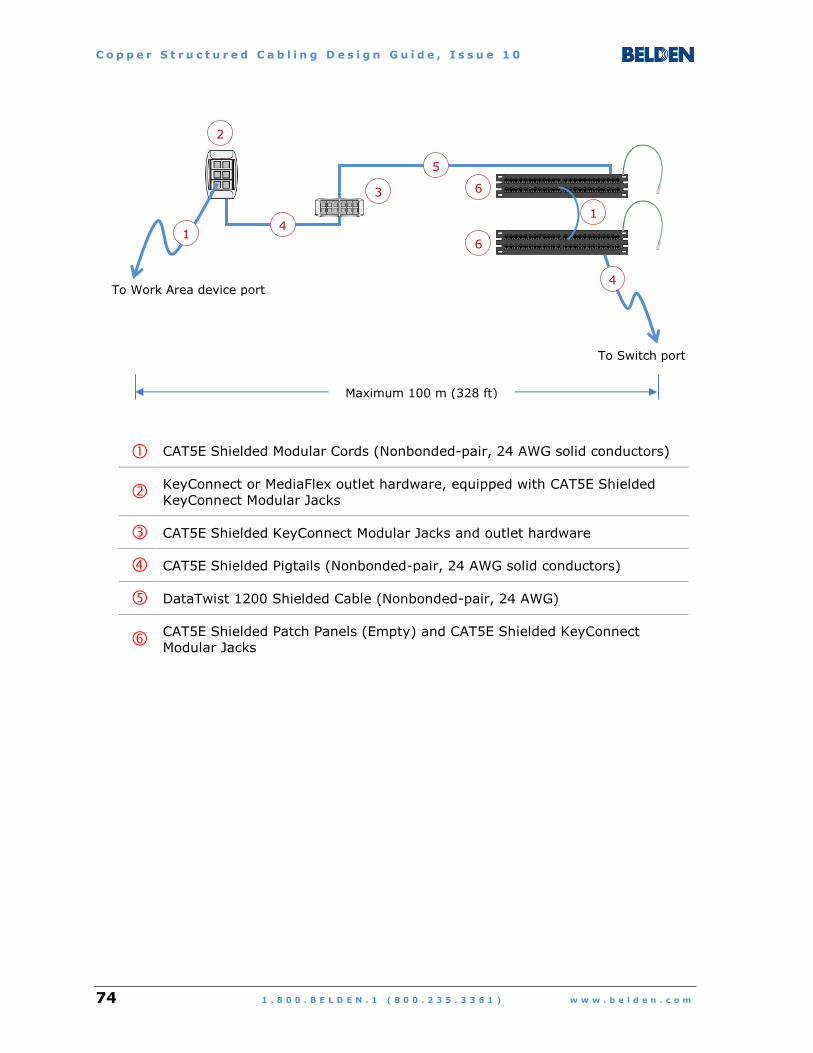
C o p p e r S t r u c t u r e d C a b l i n g D e s i g n G u i d e , I s s u e 1 0
74 1 . 8 0 0 . B E L D E N . 1 ( 8 0 0 . 2 3 5 . 3 3 6 1 ) w w w . b e l d e n . c o m
CAT5E Shielded Modular Cords (Nonbonded-pair, 24 AWG solid conductors)
KeyConnect or MediaFlex outlet hardware, equipped with CAT5E Shielded
KeyConnect Modular Jacks
CAT5E Shielded KeyConnect Modular Jacks and outlet hardware
CAT5E Shielded Pigtails (Nonbonded-pair, 24 AWG solid conductors)
DataTwist 1200 Shielded Cable (Nonbonded-pair, 24 AWG)
CAT5E Shielded Patch Panels (Empty) and CAT5E Shielded KeyConnect
Modular Jacks
To Work Area device port
2
To Switch port
Maximum 100 m (328 ft)
1 4
3
6
1
5
6
4

C o p p e r S t r u c t u r e d C a b l i n g D e s i g n G u i d e , I s s u e 1 0
w w w . b e l d e n . c o m 1 . 8 0 0 . B E L D E N . 1 ( 8 0 0 . 2 3 5 . 3 3 6 1 ) 75
ANNEX C: HDBASET CABLING CONSIDERATIONS
The High-Definition Multimedia Interface (HDMI) is a point-to-point
digital audio/video (AV) connection standard introduced in 2002.
HDMI cables and connectors are used to interconnect devices such
as televisions, Blu-ray/DVD players, audio systems, computer
monitors, gaming devices, and laptops.
The HDMI standard does not define a maximum cable length, and
most constructions are no longer than 5 m to 15 m (16 ft to 49 ft),
with signal attenuation serving as the limiting factor. Field
termination of HDMI cables is impractical due to the complexity of
the various connectors (5 types defined, up to 29 pins).
HDBaseT is a networking technology introduced in 2010 by the
HDBaseT Alliance (www.hdbaset.org). Its purpose is to enable
HDMI signals to be transported up to 100 m (328 ft) in an
uncompressed format using familiar balanced twisted-pair network
cables and modular (RJ-45) connectors.
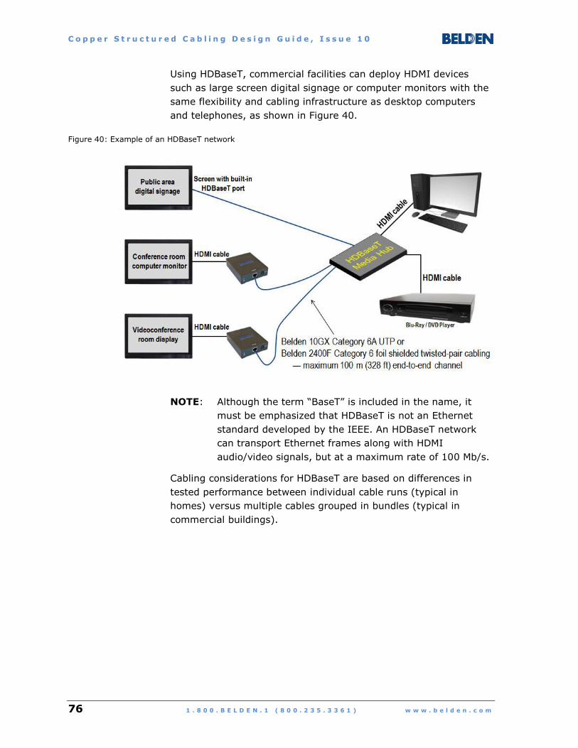
C o p p e r S t r u c t u r e d C a b l i n g D e s i g n G u i d e , I s s u e 1 0
76 1 . 8 0 0 . B E L D E N . 1 ( 8 0 0 . 2 3 5 . 3 3 6 1 ) w w w . b e l d e n . c o m
Using HDBaseT, commercial facilities can deploy HDMI devices
such as large screen digital signage or computer monitors with the
same flexibility and cabling infrastructure as desktop computers
and telephones, as shown in Figure 40.
Figure 40: Example of an HDBaseT network
NOTE: Although the term “BaseT” is included in the name, it
must be emphasized that HDBaseT is not an Ethernet
standard developed by the IEEE. An HDBaseT network
can transport Ethernet frames along with HDMI
audio/video signals, but at a maximum rate of 100 Mb/s.
Cabling considerations for HDBaseT are based on differences in
tested performance between individual cable runs (typical in
homes) versus multiple cables grouped in bundles (typical in
commercial buildings).
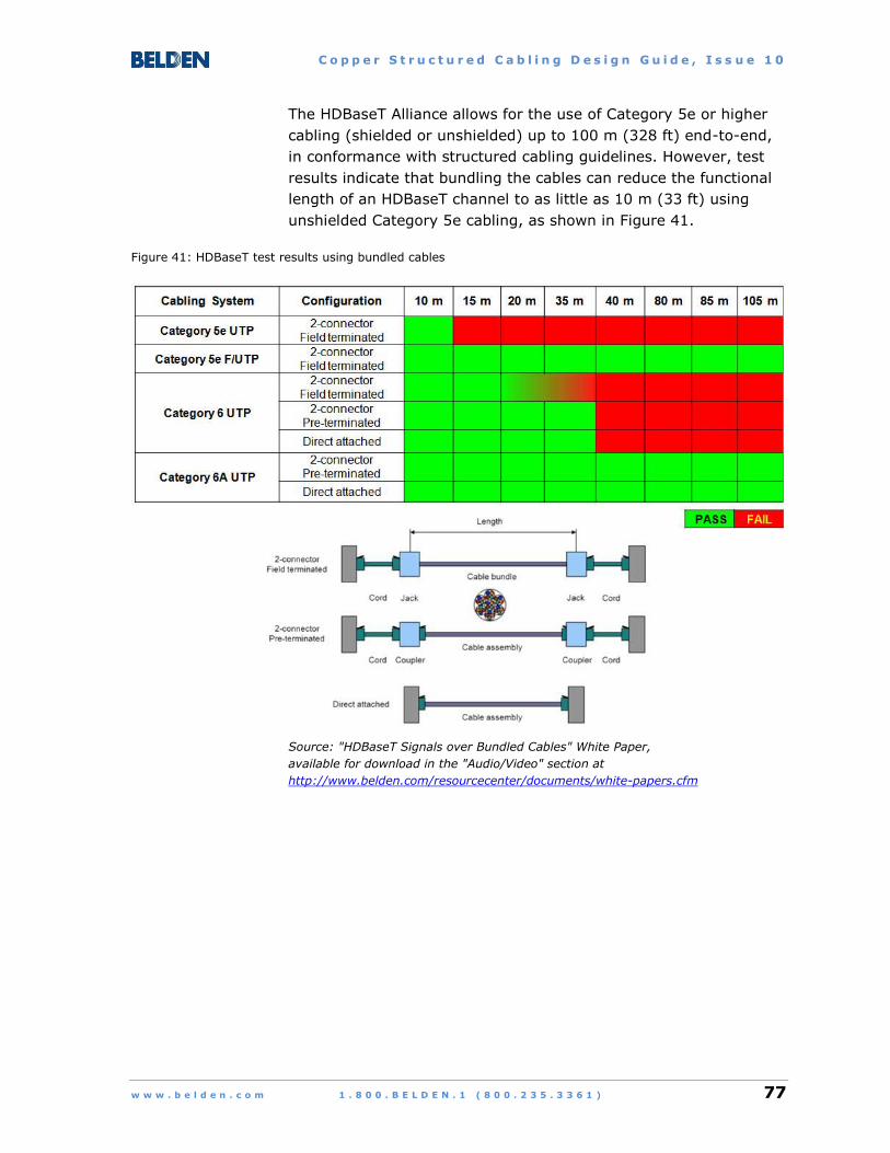
C o p p e r S t r u c t u r e d C a b l i n g D e s i g n G u i d e , I s s u e 1 0
w w w . b e l d e n . c o m 1 . 8 0 0 . B E L D E N . 1 ( 8 0 0 . 2 3 5 . 3 3 6 1 ) 77
The HDBaseT Alliance allows for the use of Category 5e or higher
cabling (shielded or unshielded) up to 100 m (328 ft) end-to-end,
in conformance with structured cabling guidelines. However, test
results indicate that bundling the cables can reduce the functional
length of an HDBaseT channel to as little as 10 m (33 ft) using
unshielded Category 5e cabling, as shown in Figure 41.
Figure 41: HDBaseT test results using bundled cables
Source: "HDBaseT Signals over Bundled Cables" White Paper,
available for download in the "Audio/Video" section at
http://www.belden.com/resourcecenter/documents/white-papers.cfm

C o p p e r S t r u c t u r e d C a b l i n g D e s i g n G u i d e , I s s u e 1 0
78 1 . 8 0 0 . B E L D E N . 1 ( 8 0 0 . 2 3 5 . 3 3 6 1 ) w w w . b e l d e n . c o m
The testing illustrated in Figure 41 can be summarized as follows:
Shorter cable lengths deliver stronger signals to the inputs of
the HDBaseT receivers and can tolerate more alien crosstalk
(undesirable noise) between cables in a bundle.
Category 5e unshielded twisted-pair (UTP) cables can only
support distances up to 10 meters without link failure in a
bundled configuration.
Category 6 cables can support distances of 30 to 40 meters
without link failure in a bundled configuration.
Category 6A UTP cables or foil shielded twisted-pair cables
(Category 6 recommended) can support distances up to
105 meters without link failure for any configuration.
NOTE: Shielded cables rely on the physical integrity of the shield
and a low impedance path to ground to provide alien
crosstalk isolation. If the shield is damaged, non-
continuous, or not connected to ground at both ends,
alien crosstalk interference between bundled shielded
cables can be worse than measured values for unshielded
cable bundles.

C o p p e r S t r u c t u r e d C a b l i n g D e s i g n G u i d e , I s s u e 1 0
w w w . b e l d e n . c o m 1 . 8 0 0 . B E L D E N . 1 ( 8 0 0 . 2 3 5 . 3 3 6 1 ) 79
Based on these outcomes, Belden offers the following
recommendations for optimal HDBaseT performance.
Category 6A UTP cabling systems are the first choice for AV
networks that will use HDBaseT technology, immediately or in
the future.
Belden IBDN 10GX Field-Terminated and Pre-Terminated
Cabling Systems
Category 6 F/UTP shielded cabling systems may be considered
as an alternate choice. Shielded Category 6 is favored over
shielded Category 5e because of lower attenuation (stronger
signal to the receiver) and better overall transmission
performance of Category 6 at higher frequencies.
Belden IBDN 2400 Field-Terminated Shielded Cabling
System
If a shielded cabling system is selected, it is critical to maintain
shield integrity at all connection points and to provide a
uniform, low resistance path to ground for all network
equipment and cabling within the premises, as specified in
ANSI/TIA-607-B “Generic Telecommunications Bonding and
Grounding (Earthing) for Customer Premises”, issued
September 2011.

C o p p e r S t r u c t u r e d C a b l i n g D e s i g n G u i d e , I s s u e 1 0
80 1 . 8 0 0 . B E L D E N . 1 ( 8 0 0 . 2 3 5 . 3 3 6 1 ) w w w . b e l d e n . c o m
REFERENCES
The Telecommunications Industry Association (TIA) is the prime
source of the standards for structured cabling systems referenced
in this document.
This section presents three groupings of standards current at the
time of publication. To view the most up-to-date listings, please
visit: http://www.tiaonline.org/standards/buy-tia-standards
Figure 42: TIA common infrastructure standards

C o p p e r S t r u c t u r e d C a b l i n g D e s i g n G u i d e , I s s u e 1 0
w w w . b e l d e n . c o m 1 . 8 0 0 . B E L D E N . 1 ( 8 0 0 . 2 3 5 . 3 3 6 1 ) 81
Figure 43: TIA standards by premise type
Figure 44: TIA twisted-pair cabling standards