copyright © 2006, dr. dharma p. agrawal and dr. qing-an zeng. all rights reserved. 1 mobile...
TRANSCRIPT

1Copyright © 2006, Dr. Dharma P. Agrawal and Dr. Qing-An Zeng. All rights reserved.
Mobile Communication Systems
Chapter 9

2Copyright © 2006, Dr. Dharma P. Agrawal and Dr. Qing-An Zeng. All rights reserved.
Outline Cellular System Infrastructure Registration Handoff Parameters and Underlying Support Roaming Support Multicasting Security and Privacy Firewalls and System Security

3Copyright © 2006, Dr. Dharma P. Agrawal and Dr. Qing-An Zeng. All rights reserved.
Cellular System Infrastructure
MSC…
HLR
VLR
EIR
AUC
Gateway MSC
MSC
…
PSTN/ISDN
BSCBTS
BTS
BTS
MS
Base Station System
BSCBTS
BTS
BTS
…
MS
Base Station System
…

4Copyright © 2006, Dr. Dharma P. Agrawal and Dr. Qing-An Zeng. All rights reserved.
VLR/HLR/AUC/EIR VLR contains information about all visiting
MSs in that particular area of MSC. VLR has pointers to the HLR’s of visiting MS. VLR helps in billing and access permission to
the visiting MS. AUC provides authentication and encryption
parameters. EIR contains identity of equipments that
prevents service to unauthorized MSs.
5Copyright © 2006, Dr. Dharma P. Agrawal and Dr. Qing-An Zeng. All rights reserved.
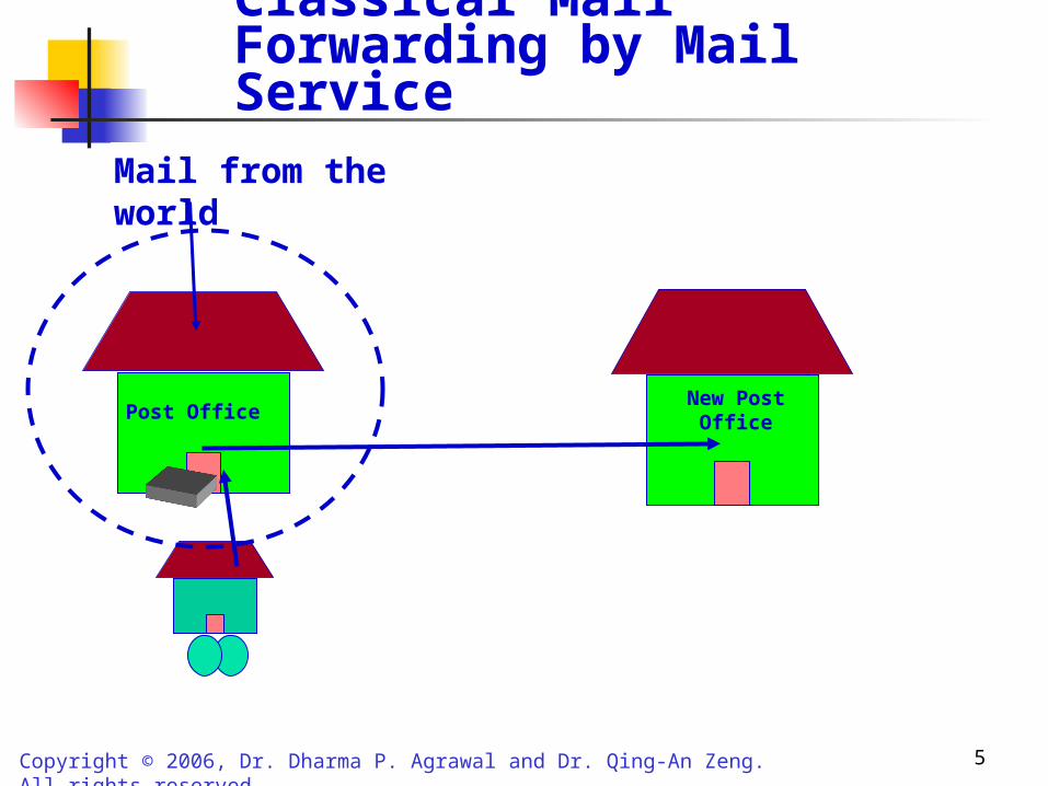
Classical Mail Forwarding by Mail Service
Post OfficeNew Post
Office
Mail from the world

6Copyright © 2006, Dr. Dharma P. Agrawal and Dr. Qing-An Zeng. All rights reserved.
PSTN
MS
HomeMobile
Switching Center
HLR Home network
Visitingarea
Caller
VisitingMobile
Switching Center
VLR
MS
1
Location update request Using Becon Signals
Update location Info. sent to HLR
2
Automatic Location Update
7Copyright © 2006, Dr. Dharma P. Agrawal and Dr. Qing-An Zeng. All rights reserved.
PSTN
MS
homeMobile
Switching Center
HLR Home Network
VisitingArea
Caller
Mobile Switching
Center
VLR
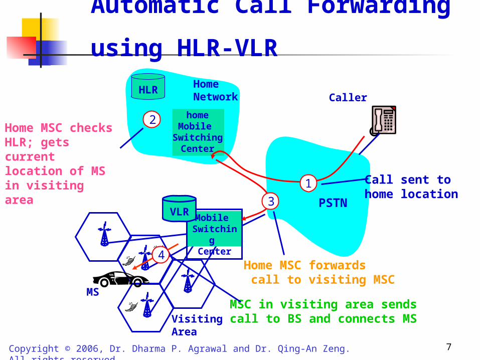
Automatic Call Forwarding using HLR-VLR
1 Call sent to home location
2Home MSC checksHLR; gets current location of MSin visiting area
3
Home MSC forwards call to visiting MSC
4
MSC in visiting area sendscall to BS and connects MS

8Copyright © 2006, Dr. Dharma P. Agrawal and Dr. Qing-An Zeng. All rights reserved.
Redirection of Call to MS at a Visiting Location
BS
MS
Cell where MS is currently located
Visiting MSC
VLR
Another MSC
Through backbone
HLR
Home MSC
Call routed as per called number to MS
Home MSC
9Copyright © 2006, Dr. Dharma P. Agrawal and Dr. Qing-An Zeng. All rights reserved.
Registration Wireless system needs to know whether MS is currently
located in its home area or some other area (routing of incoming calls).
This is done by periodically exchanging signals between BS and MS known as Beacons.
BS periodically broadcasts beacon signal (1 signal per second) to determine and test the MSs around.
Each MS listens to the beacon, if it has not heard it previously then it adds it to the active beacon kernel table.
This information is used by the MS to locate the nearest BS. Information carried by beacon signal: cellular network
identifier, timestamp, gateway address ID of the paging area, etc.

10Copyright © 2006, Dr. Dharma P. Agrawal and Dr. Qing-An Zeng. All rights reserved.
Steps for Registration
MS listens to a new beacon, if it’s a new one, MS adds it to the active beacon kernel table.
If MS decides that it has to communicate through a new BS, kernel modulation initiates handoff process.
MS locates the nearest BS via user level processing. The visiting BS performs user level processing and
decides: Who the user is? What are its access permissions? Keeping track of billing.
Home site sends appropriate authentication response to the current serving BS.
The BS approves/disapproves the user access.
11Copyright © 2006, Dr. Dharma P. Agrawal and Dr. Qing-An Zeng. All rights reserved.
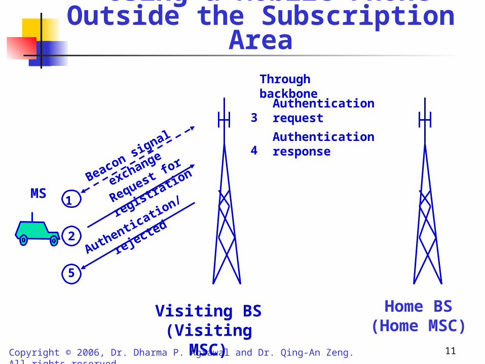
Using a Mobile Phone Outside the Subscription Area
Visiting BS(Visiting MSC)
MSBeacon sig
nal exchange
1Request f
or registration
2
Authentication/rejected
5
Home BS(Home MSC)
3Authentication request
4Authentication response
Through backbone

12Copyright © 2006, Dr. Dharma P. Agrawal and Dr. Qing-An Zeng. All rights reserved.
Applications and Characteristics of Beacon Signals
Application Frequency band Information carried
Cellular networks 824-849 MHz (AMPS/CDPD), 1,850-1,910 MHz (GSM)
Cellular IP network identifier,Gateway IP address, Paging area ID,
Timestamp
Wireless LANs
(discussed in Chapter 14)
902-928 MHz (industrial, scientific, and medical band for analog and mixed signals) 2.4-2.5GHz (ISM band for digital signals)
Traffic indication map
Ad hoc networks(discussed in
Chapter 13)
902-928 MHz (ISM band for analog and mixed signals) 2.4-2.5 GHz (ISM band for digital signals)
Network node identify
GPS (discussed in Chapter 11)
1575.42 MHz Timestamped orbital map and astronomical information
Search and rescue 406 and 121.5 MHz Registration country and ID of vessel or aircraft in distress
Mobile robotics 100 KHz - 1 MHz Position of pallet or payload
Location tracking 300 GHz - 810 THz (infrared) Digitally encoded signal to identify user's location
Aid to the impaired 176 MHz Digitally coded signal uniquely identifying physical locations

13Copyright © 2006, Dr. Dharma P. Agrawal and Dr. Qing-An Zeng. All rights reserved.
Handoff Parameters and Underlying Support
Change of radio resources from one cell to an adjacent one.
Handoff depends on cell size, boundary length, signal strength, fading, reflection, etc.
Handoff can be initiated by MS or BS and could be due to Radio link Network management Service issues

14Copyright © 2006, Dr. Dharma P. Agrawal and Dr. Qing-An Zeng. All rights reserved.
Handoff Parameters (Cont’d)
Radio link handoff is due to mobility of MS.
It depends on: Number of MSs in the cell Number of MSs that have left the cell Number of calls generated in the cell Number of calls transferred from the
neighboring cells Number and duration of calls terminated in
the cell Number of calls that were handoff to
neighboring cells Cell dwell time

15Copyright © 2006, Dr. Dharma P. Agrawal and Dr. Qing-An Zeng. All rights reserved.
Handoff Parameters (Cont’d)
Network management may cause handoff if there is drastic imbalance of traffic in adjacent cells and optimal balance of resources is required.
Service related handoff is due to the degradation of QoS (quality of service).

16Copyright © 2006, Dr. Dharma P. Agrawal and Dr. Qing-An Zeng. All rights reserved.
Time for Handoff
Factors deciding right time for handoff: Signal strength Signal phase Combination of above two Bit error rate (BER) Distance
Need for Handoff is determined by: Signal strength CIR (carrier to interference ratio).

17Copyright © 2006, Dr. Dharma P. Agrawal and Dr. Qing-An Zeng. All rights reserved.
Handoff Region
BSi
Signal strength due to BSi
X2
MSX4
Pmin
Pi(x)
E
Signal strength due to BSj
X1 X3X5 Xth
BSj
Pj(x)
By looking at the variation of signal strength from either base station it is possible to decide on the optimum area where handoff can take place.

18Copyright © 2006, Dr. Dharma P. Agrawal and Dr. Qing-An Zeng. All rights reserved.
Handoff initiation (Cont’d)
Region X3-X4 indicates the handoff area, where depending on other factors, the handoff needs to be performed.
One option is to do handoff at X5 where the two signal strengths are equal.
If MS moves back and forth around X5, it will result in too frequent handoffs (ping-pong effect).
Therefore MS is allowed to continue with the existing BS till the signal strength decreases by a threshold value E.
Different cellular systems follow different handoff procedure.
19Copyright © 2006, Dr. Dharma P. Agrawal and Dr. Qing-An Zeng. All rights reserved.
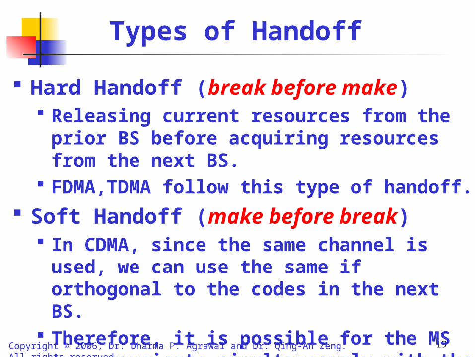
Types of Handoff
Hard Handoff (break before make) Releasing current resources from the prior BS before
acquiring resources from the next BS. FDMA,TDMA follow this type of handoff.
Soft Handoff (make before break) In CDMA, since the same channel is used, we can use
the same if orthogonal to the codes in the next BS. Therefore, it is possible for the MS to communicate
simultaneously with the prior BS as well as the new BS.

20Copyright © 2006, Dr. Dharma P. Agrawal and Dr. Qing-An Zeng. All rights reserved.
Hard Handoff
BS1 BS2MS
(a). Before handoff
BS1 BS2MS
(b). During handoff (No connection)
BS1 BS2MS
(c). After handoff

21Copyright © 2006, Dr. Dharma P. Agrawal and Dr. Qing-An Zeng. All rights reserved.
Soft Handoff (CDMA only)
BS1 BS2MS
(b). During handoff
BS1 BS2MS
BS1 BS2MS
(c). After handoff(a). Before handoff

22Copyright © 2006, Dr. Dharma P. Agrawal and Dr. Qing-An Zeng. All rights reserved.
Roaming Support
To move from a cell controlled by one MSC area to a cell connected to another MSC.
Beacon signals and the use of HLR-VLR allow the MS to roam anywhere provided the same service provider using that particular frequency band, is there in that region.

23Copyright © 2006, Dr. Dharma P. Agrawal and Dr. Qing-An Zeng. All rights reserved.
Roaming Support
BS1 BS2MS
Home MSC
Visiting MSC
BS1 BS2MS
Home MSC
Visiting MSC
MS moves

24Copyright © 2006, Dr. Dharma P. Agrawal and Dr. Qing-An Zeng. All rights reserved.
Handoff Scenarios with Different Degree of Mobility
PSTN
Paging Area 1
MSC2
c
MSC3
d
MSC4
Paging Area 2
e
MS
MSC1
a b

25Copyright © 2006, Dr. Dharma P. Agrawal and Dr. Qing-An Zeng. All rights reserved.
Possible Handoff Situations
Assume MSC1 to be the home of the MS for registration, billing, authentication, etc.
When handoff is from position “a” to “b”, the routing can be done by MSC1 itself.
When handoff is from position “b” to “c” , then bi-directional pointers are set up to link the HLR of MSC1 to VLR of MSC2.
When handoff occurs at “d” or “e”, routing of information using HLR-VLR may not be adequate (“d” is in a different paging area).
Concept of Backbone network.

26Copyright © 2006, Dr. Dharma P. Agrawal and Dr. Qing-An Zeng. All rights reserved.
Information Transmission Path when MS Hands Off from “b” to “c”
Connection Path after handoff
MSC1 HLR
MSC2 VLR
a b c
Information to MS being sent
Initial path of information transfer
MS

27Copyright © 2006, Dr. Dharma P. Agrawal and Dr. Qing-An Zeng. All rights reserved.
Illustration of MSC Connections to Backbone Network and Routing/Rerouting
MSC
Router
Paging area 1 (PA1) Paging area 2 (PA2)
MSC1
(a,b)MSC2
(c)MSC3
(d) MSC4
(e)
(a,b,c,d,e)
(a,b)
(a,b,c,d)
(d)R3
R4 R6
R2
R5
R9
R1
R7
R10
R12
R8
R11 R13
From rest of the backbone
(c) (e)
R: Routers

28Copyright © 2006, Dr. Dharma P. Agrawal and Dr. Qing-An Zeng. All rights reserved.
Backbone Network
Routing done according to the topology and connectivity of the backbone network.
The dotted lines show the possible paths for a call headed for different MS locations.
One option is to find a router along the original path, from where a new path needs to start to reach the MSC along the shortest path.

29Copyright © 2006, Dr. Dharma P. Agrawal and Dr. Qing-An Zeng. All rights reserved.
Home Agents (HA), Foreign Agents (FA) and Mobile IP
Two important software modules are associated with routers, home agent (HA) and foreign agent (FA).
MS is registered with a router, mostly a router closest to the home MSC can be used to maintain its HA.
A router other than closest one could also serve as an HA. Once a MS moves from the home network, a software
module in the new network FA assists MS by forwarding packets for the MS.
This functionality is somewhat similar to HLR-VLR.
30Copyright © 2006, Dr. Dharma P. Agrawal and Dr. Qing-An Zeng. All rights reserved.
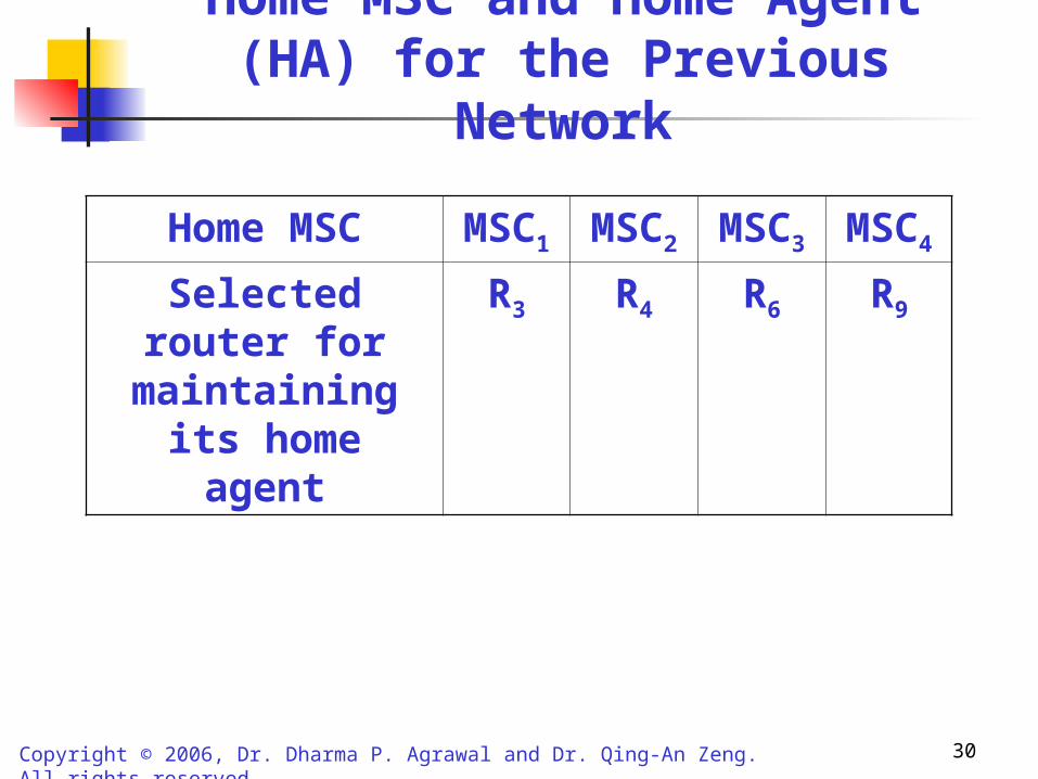
Home MSC MSC1 MSC2 MSC3 MSC4
Selected router for maintaining its
home agent
R3 R4 R6 R9
Home MSC and Home Agent (HA) for the Previous Network

31Copyright © 2006, Dr. Dharma P. Agrawal and Dr. Qing-An Zeng. All rights reserved.
Call Establishment using HA-FA
Whenever a MS moves to a new network, it still retains its initial HA.
The MS detects the FA of the new network, by sensing the periodic beacon signals which FA transmits.
MS can also itself send agent solicitation messages to which FA responds.
When FA detects a new MS, it allocates a CoA (care of address) to the MS, using dynamic host configuration protocol (DHCP).
Once MS receives CoA, it registers its CoA with its HA and the time limit binding for its validity.
Such registration is initiated either directly by MS to the HA of the home router or indirectly through FA.
32Copyright © 2006, Dr. Dharma P. Agrawal and Dr. Qing-An Zeng. All rights reserved.
Call Establishment (Cont’d)
HA confirms its binding through a reply to the MS. A message sent from an arbitrary source to the MS at the
home address is received by the HA. Binding is checked, the CoA of the MS is encapsulated in
the packet and forwarded to the network. If CoA of the FA is used, then packet reaches FA, it
decapsulates packet and passes to MS at the link layer. In an internet environment, it is called Mobile IP. After binding time, if MS still wants to have packets
forwarded through HA, it needs to renew its registration. When MS returns to its home network, it intimates its HA.

33Copyright © 2006, Dr. Dharma P. Agrawal and Dr. Qing-An Zeng. All rights reserved.
FA
3 CoA or C-CoA created
MSHA
Here is my HA and binding information
2
OK, send information
1
1”
1’
Beacon Signal
I am new here
(Any one new)
Acknowledge Registration + binding
4
4’ Same as step
Here is CoA or co-located CoA (C-CoA) for this MS
4
4” Same as step 4
Registration Process Between FA, MS, and HA When the MS Moves to a Paging area

34Copyright © 2006, Dr. Dharma P. Agrawal and Dr. Qing-An Zeng. All rights reserved.
Source To MS Payload DataIncoming message for MS
HA
HA CoA/C-CoA Source To MS Payload Data
Encapsulation
FA
Forwarding through intermediate router if CoA used Forwarding
through intermediate router if C-CoA used
Source To MS Payload Data
Decapsulation done at MSMS
Message Forwarding using HA-FA Pair

35Copyright © 2006, Dr. Dharma P. Agrawal and Dr. Qing-An Zeng. All rights reserved.
Routing in Backbone Routers
How FA finds HA of the MS ? One approach is to have a global table at each
router of each MSC so that the route from FA to HA for that MS can be determined.
Disadvantages: Information too large, one network might not like to give out information about all its routers to any external network (only gateways information is provided).
Use of Distributed Routing Scheme.

36Copyright © 2006, Dr. Dharma P. Agrawal and Dr. Qing-An Zeng. All rights reserved.
PA1 PA2
PA3
PA4
PA5
Router X
Router W
Router Z
Network 1
Network 2
MS moves
Illustration of Paging Areas (PAs) and Backbone Router Interconnect
PA1 PA2
PA3
PA4
PA5
Router Y
Network 1
Network 2

37Copyright © 2006, Dr. Dharma P. Agrawal and Dr. Qing-An Zeng. All rights reserved.
Route to PA
Next hop
Route to PA
Next hop
Route to PA
Next hop
Route to PA
Next hop
1 X 1 - 1 X 1 Y
2 X 2 - 2 X 2 Y
3 X 3 Y 3 Z 3 -
4 X 4 Y 4 Z 4 -
5 X 5 Y 5 Z 5 -
Table at routerW
Table at router X
Table at router Y
Table at routerZ
Distributed Routing Table and Location PAs

38Copyright © 2006, Dr. Dharma P. Agrawal and Dr. Qing-An Zeng. All rights reserved.
Multicasting
Process of transmitting messages from a source to multiple recipients by using a group address for all hosts that wish to be the members of the group.
Reduces number of messages to be transmitted as compared to multiple unicasting.
Useful in video/audio conferencing, multi party games.
39Copyright © 2006, Dr. Dharma P. Agrawal and Dr. Qing-An Zeng. All rights reserved.
Multicasting
Multicasting can be performed either by building a source based tree or core based tree.
In source based tree , for each source of the group a shortest path is maintained, encompassing all the members of the group, with the source being the root of the tree.
In core based tree, a particular router is chosen as a core and a tree is maintained with the core being the root.
-- Every source forwards the packet to a core router, which then forwards it on the tree to reach all members of the multicast group.

40Copyright © 2006, Dr. Dharma P. Agrawal and Dr. Qing-An Zeng. All rights reserved.
Multicasting
Bi-directional Tunneling (BT) and Remote Subscription approaches have been proposed by IETF for providing multicast over Mobile IP.
In BT approach, whenever a MS moves to a foreign network, HA is responsible for forwarding the multicast packets to the MS via FA.
In Remote Subscription protocol, whenever a MS moves to a foreign network, the FA (if not already a member of multicast group) sends a tree join request.
41Copyright © 2006, Dr. Dharma P. Agrawal and Dr. Qing-An Zeng. All rights reserved.
Multicasting
Remote Subscription based approach is simple and prevents packet duplication and non optimal path delivery.
It can cause data interruption till the FA is connected to the tree.
It results in a number of tree join and tree leave requests when MS are in continuous motion.
In contrast, in the BT approach, the HA creates a bi-directional tunnel to FA and encapsulates the packets for MS.
FA then forwards the packets to the MS.

42Copyright © 2006, Dr. Dharma P. Agrawal and Dr. Qing-An Zeng. All rights reserved.
Multicasting
BT approach prevents data disruption due to the movement of MS.
But causes packet duplication if several MSs of the same HA, that have subscribed to the same multicast group move to same FA.
Also causes Tunnel Convergence Problem, where one FA may have several MSs subscribed to the same group, belonging to different HAs and each HA may forward a packet for its MSs to the same FA.

43Copyright © 2006, Dr. Dharma P. Agrawal and Dr. Qing-An Zeng. All rights reserved.
HA
Multicast packets from the multicast tree
MS1
MS2
MS3
FA
MS 1
MS 2
MS 3
Packet Duplication in BT Tunnel Approach

44Copyright © 2006, Dr. Dharma P. Agrawal and Dr. Qing-An Zeng. All rights reserved.
Multicast packets from the multicast tree
HA 1
HA 2
HA 3
CoA (MS1)
CoA (MS2)
CoA (MS3)
CoA (MS4)
MS 1
MS 2
MS 3
MS 4
FA
Tunnel Convergence Problem

45Copyright © 2006, Dr. Dharma P. Agrawal and Dr. Qing-An Zeng. All rights reserved.
Multicasting
To overcome Tunnel Convergence Problem, MoM protocol is proposed wherein the FA selects one of the HAs, called the Designated Multicast Service Provider (DMSP), from the HA List for a particular group.
The remaining HAs do not forward packets to FA.

46Copyright © 2006, Dr. Dharma P. Agrawal and Dr. Qing-An Zeng. All rights reserved.
Multicast packets from the multicast tree
HA 1
HA 2
HA 3
CoA (MS1)
CoA (MS2)
CoA (MS3)
MS 1
MS 2
MS 3
MS 4
Stop
Stop
Forward
DMSP Selection
FA
CoA (MS4)
Illustration of MoM Protocol

47Copyright © 2006, Dr. Dharma P. Agrawal and Dr. Qing-An Zeng. All rights reserved.
Security and Privacy
Transfer through an open air medium makes messages vulnerable to various attacks.
One such problem is “Jamming” by a very powerful transmitting antenna.
Can be overcome by using frequency hopping. Many encryption techniques used so that
unauthorized users cannot interpret the signals.

48Copyright © 2006, Dr. Dharma P. Agrawal and Dr. Qing-An Zeng. All rights reserved.
Encryption Techniques
Permuting the bits in a pre specified manner before transmitting them.
Such permuted information can be reconstructed by using reverse operation.
This is called “Data Encryption Standard (DES)” on input bits.

49Copyright © 2006, Dr. Dharma P. Agrawal and Dr. Qing-An Zeng. All rights reserved.
Input Output
Simple Permutation Function
1
2
3
4
5
6
7
8
1
5
2
6
3
7
4
8
W
I
R
E
L
E
S
S
W
L
I
E
R
S
E
S

50Copyright © 2006, Dr. Dharma P. Agrawal and Dr. Qing-An Zeng. All rights reserved.
Initial Bit Patterns and effect of before Transmission and after Reception using DES
(b) Permutation of information sequence before transmission
57 49 41 33 25 17 9 1
61 53 45 37 29 21 13 5
58 50 42 34 26 18 10 2
62 54 46 38 30 22 14 6
59 51 43 35 27 19 11 3
63 55 47 39 31 23 15 7
60 52 44 36 28 20 12 4
64 56 48 40 32 24 16 8
(c) Permutation to be performed on received information sequence
8 24 40 56 16 32 48 64
7 23 39 55 15 31 47 63
6 22 38 54 14 30 46 62
5 21 37 53 13 29 45 61
4 20 36 52 12 28 44 60
3 19 35 51 11 27 43 59
2 18 34 50 10 26 42 58
1 17 33 49 9 25 41 57
1 2 3 4 5 6 7 8
9 10 11 12 13 14 15 16
17 18 19 20 21 22 23 24
25 26 27 28 29 30 31 32
33 34 35 36 37 38 39 40
41 42 43 44 45 46 47 48
49 50 51 52 53 54 55 56
57 58 59 60 61 62 63 64
(a) Information sequence to be transmitted
51Copyright © 2006, Dr. Dharma P. Agrawal and Dr. Qing-An Zeng. All rights reserved.
Encryption Techniques
A complex encryption scheme involves transforming input blocks to some coded form.
Encoded information is uniquely mapped back to useful information.
Simplest transformation involves logical or arithmetic or both operations.

52Copyright © 2006, Dr. Dharma P. Agrawal and Dr. Qing-An Zeng. All rights reserved.
A Generic Process of Encoding and Decoding
Information
block
Transmitted signal
Encoded
signal
Encoding
at
transmitter
Information
block
Received signal
DecodingEncoded
signal
(Original)receiver
at
53Copyright © 2006, Dr. Dharma P. Agrawal and Dr. Qing-An Zeng. All rights reserved.
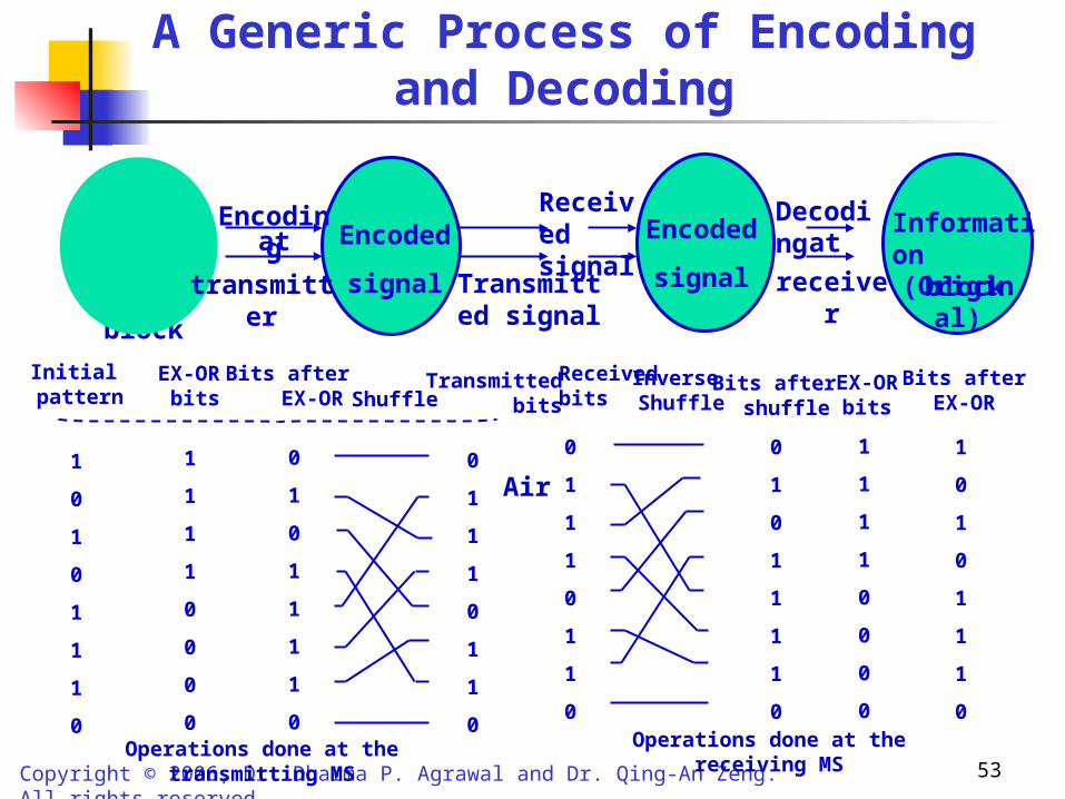
A Generic Process of Encoding and Decoding
Information
block
Encoding
Transmitted signal
Received signal
DecodingEncoded
signal
Encoded
signal
Informationblock
(Original)
at
transmitter receiver
at
Operations done at the transmitting MS
1
0
1
0
1
1
1
0
Initial pattern
1
1
1
1
0
0
0
0
EX-OR bits
0
1
0
1
1
1
1
0
Bits after EX-OR Shuffle
0
1
1
1
0
1
1
0
Transmitted bits
0
1
1
1
0
1
1
0
Received bits
Inverse Shuffle
0
1
0
1
1
1
1
0
Bits after shuffle
1
1
1
1
0
0
0
0
EX-ORbits
1
0
1
0
1
1
1
0
Bits afterEX-OR
Air
Operations done at the receiving MS

54Copyright © 2006, Dr. Dharma P. Agrawal and Dr. Qing-An Zeng. All rights reserved.
Key K1
f+
Input (64 bits)
Initial Permutation (IP)
32 bits 32 bits
Left half: L1 Right half: R1
Inverse initial permutation (IP –1)
Coded Output
Permutation and Coding of Information
f+
Left half: L1 = R1 R1 = L1 f(R1, K1)+
R16 = L16 f(R15, K16)+ Left half: L16 = R15

55Copyright © 2006, Dr. Dharma P. Agrawal and Dr. Qing-An Zeng. All rights reserved.
Authentication
Making sure user is genuine. Using a Hash Function from an associated
unique identification of the user (not full proof) Another approach is to use two different
interrelated keys. One known only to system generating the key
(private key) , other used for sending to outside world (public key).
RSA algorithm (best known public key system)

56Copyright © 2006, Dr. Dharma P. Agrawal and Dr. Qing-An Zeng. All rights reserved.
Public/Private Key Authentication Steps
System User i
(1) Compute Public Key for User i from its private key
usually done off line
(2) Send Public Key
Save Public Key
(4) Verify using private key of User i
(5) Authentication ResultSystem User i
Use public key to generate signature.
(3) ID, Signature
System User ion-line test
(1) Compute Public Key for User i from its private key
usually done off line
(2) Send Public Key
Save Public Key

57Copyright © 2006, Dr. Dharma P. Agrawal and Dr. Qing-An Zeng. All rights reserved.
Authentication (RSA Algorithm)
Let us take p=3 and q=11, giving n=pq=33
Assume e=7, gives (n,e) as public key of (33,7)
For message m=4, c= me| mod n = 47 mod 33 = 16
d is computed such that ed mod (p-1)(q-1) = ed mod 20= 1, thus, d=3, giving private key of (33,3)
After receiving c=16, compute cd mod 30 = 16 3 mod 33 =4

58Copyright © 2006, Dr. Dharma P. Agrawal and Dr. Qing-An Zeng. All rights reserved.
Authentication (RSA Algorithm)• In RSA method 2 large prime numbers (p,q) are selected.• n = p*q,• A number e is selected to use (n,e) as the public key and is
transmitted to the user,• User stores this, whenever a message m< n needs to be
transmitted, user computes c = me| mod n and sends to the system.• After receiving c, the system computes cd|mod n where d is computed
using the private key (n,e) • cd|mod n = (me|mod n) d |mod n = (me)d |mod n
= m ed|mod n
• To make this equal to m, ed should be equal to 1.• This means e and d need to be multiplicative inverse using mod n
(or mod p*q)• This can be satisfied if e is prime with respect to (p-1)*(q-1) • Using this restriction original message is reconstructed.

59Copyright © 2006, Dr. Dharma P. Agrawal and Dr. Qing-An Zeng. All rights reserved.
Base Station
Select p and q as two prime numbers
n = p*q
1 < e < n
Public Key (n,e) Mobile Station
Save public key (n, e)
Base Station
Compute d from e
(n,d) private key
Receive c
Mobile Station
Message m < n
Sent as c = me|mod n
c
Base Station
Compute cd|mod n = mde|mod n = m
If de = 1
AuthenticationMobile station OK
Message Authentication using Public/Private Keys

60Copyright © 2006, Dr. Dharma P. Agrawal and Dr. Qing-An Zeng. All rights reserved.
Base StationMobile Station
(ID)e|mod n
Authentication
(a) Authentication based on ID
Base Station
(ID)e|mod n
R: Random Number as a Challenge Mobile
StationSend Re|mod n
Authentication
(b) Authentication using a challenge
Authentication of a MS by the BS

61Copyright © 2006, Dr. Dharma P. Agrawal and Dr. Qing-An Zeng. All rights reserved.
Wireless System Security
Basic services of security: Confidentiality Non-repudiation: sender and receiver
cannot deny the transmission. Authentication: sender of the information is
correctly identified. Integrity: content of the message can only be
modified by authorized user. Availability: resources available only to
authorized users.
62Copyright © 2006, Dr. Dharma P. Agrawal and Dr. Qing-An Zeng. All rights reserved.
Wireless System Security
Security Mechanisms: Security Prevention: Enforces security
during the operation of the system. Security Detection: Detects attempts to
violate security. Recovery: Restore the system to pre-
security violation state.

63Copyright © 2006, Dr. Dharma P. Agrawal and Dr. Qing-An Zeng. All rights reserved.
Cost Function of a Secured Wireless System
Expected total cost with violations
Cost
Security Level
100%
Expected total cost
Cost for Security enhancing mechanisms
Optimal Level

64Copyright © 2006, Dr. Dharma P. Agrawal and Dr. Qing-An Zeng. All rights reserved.
Security Threat Categories
S Source D DestinationSource I Intruder
Interruption
Message
S I D
Fabrication
MessageS
I
D
Modification
Message
MessageS
I
D
Interception
Message
MessageS
I
D

65Copyright © 2006, Dr. Dharma P. Agrawal and Dr. Qing-An Zeng. All rights reserved.
Wireless Security
Active Attacks: When data modification or false data transmission takes place. Masquerade: one entity pretends to be a
different entity. Replay: information captured and retransmitted
to produce unauthorized effect. Modification of message Denial of service (DoS)
Passive Attacks: Goal of intruder is to obtain information (monitoring, eavesdropping on transmission)

66Copyright © 2006, Dr. Dharma P. Agrawal and Dr. Qing-An Zeng. All rights reserved.
Firewalls and System Security
Firewall carries out traffic filtering, web authentication, and other security mechanisms.
Filtering can be configured by fixing: Source IP Destination IP Source TCP/UDP port Destination TCP/UDP port Arrival interface Destination interface IP protocol
Firewall resides at wireless access point to carry out authentication