copyright © 2010 altair engineering, inc. all rights reserved.altair proprietary and confidential...
TRANSCRIPT

Copyright © 2010 Altair Engineering, Inc. All rights reserved. Altair Proprietary and Confidential Information
Section 7
Mesh Control

Copyright © 2010 Altair Engineering, Inc. All rights reserved. Altair Proprietary and Confidential Information
The automated meshing process in SimLab can generate mesh that is suitable for the
following Analysis Types.
Analysis type
Durability / Stress analysis
NVH analysis
Acoustic analysis
Drop test
Fluid analysis
For each of the above analysis types, the desired mesh density and the quality of the
mesh differs. In SimLab, the output mesh is controlled by specifying Mesh Controls.
Mesh controls are applied directly to the CAD models.
Mesh Control Overview

Copyright © 2010 Altair Engineering, Inc. All rights reserved. Altair Proprietary and Confidential Information
Mesh controls are classified under the following types,
Global mesh controls
• It is assigned to bodies or assemblies and all underlying geometry entities,
(faces and edges), will inherit this global mesh control.
• It is mandatory to specify the global mesh control.
Local mesh controls
Local mesh controls are used to control the mesh in a particular region.
It over rides the global mesh controls.
It is assigned to bodies, faces and edges.
Mesh Control - Classifications

Copyright © 2010 Altair Engineering, Inc. All rights reserved. Altair Proprietary and Confidential Information
Global mesh controls are defined while surface meshing or volume meshing.
Surface meshing
Surface meshing is used to generate a surface mesh body from a CAD body.
Surface elements supported are Tri3, Tri, Quad4, Bar2 and Bar3.
Volume meshing
Volume meshing is used to generate a volume mesh body from a CAD body
or a surface mesh body.
Volume elements supported are Tet4, Tet10, Wedge6 and Hex8.
Global Mesh Controls

Copyright © 2010 Altair Engineering, Inc. All rights reserved. Altair Proprietary and Confidential Information
Global Mesh ControlsSurface meshing

Copyright © 2010 Altair Engineering, Inc. All rights reserved. Altair Proprietary and Confidential Information
Global Mesh ControlsVolume meshing
Input

Copyright © 2010 Altair Engineering, Inc. All rights reserved. Altair Proprietary and Confidential Information
Global Mesh ControlsVolume meshing
Output
Copyright © 2010 Altair Engineering, Inc. All rights reserved. Altair Proprietary and Confidential Information
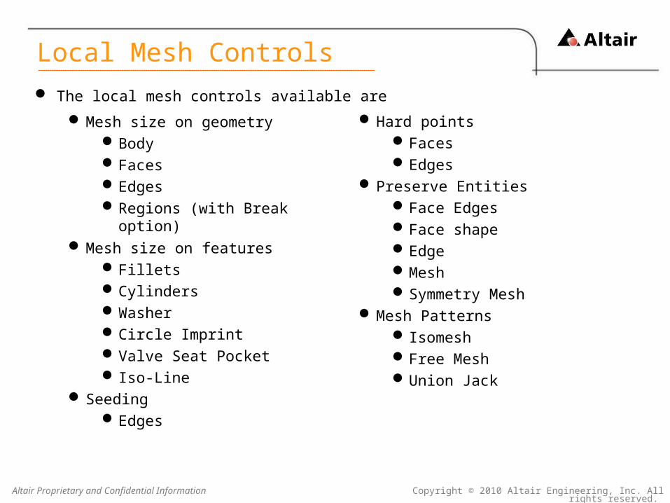
Mesh size on geometryBodyFacesEdgesRegions (with Break option)
Mesh size on featuresFilletsCylindersWasherCircle ImprintValve Seat Pocket Iso-Line
SeedingEdges
Hard pointsFaces Edges
Preserve EntitiesFace EdgesFace shapeEdgeMeshSymmetry Mesh
Mesh Patterns IsomeshFree MeshUnion Jack
The local mesh controls available are
Local Mesh Controls

Copyright © 2010 Altair Engineering, Inc. All rights reserved. Altair Proprietary and Confidential Information
Following are the local mesh control parameters,
1. Face Mesh Control
2. Edge Mesh Control
3. Body Mesh Control
4. Fillet Mesh Control
5. Cylinder Mesh Control
6. Washer Mesh Control
7. Circle Imprint Mesh Control
8. Region Mesh Control
9. Valve Seat Pocket Mesh Control
10.Iso-Line Mesh Control
11.Volume Layer Mesh Control
Local Mesh Controls

Copyright © 2010 Altair Engineering, Inc. All rights reserved. Altair Proprietary and Confidential Information
Face Mesh Control is used to control the mesh on the selected local faces. A
uniform mesh is generated on the face that has the face mesh control specified.
Input Output Mesh
1. Face Mesh Control
Copyright © 2010 Altair Engineering, Inc. All rights reserved. Altair Proprietary and Confidential Information
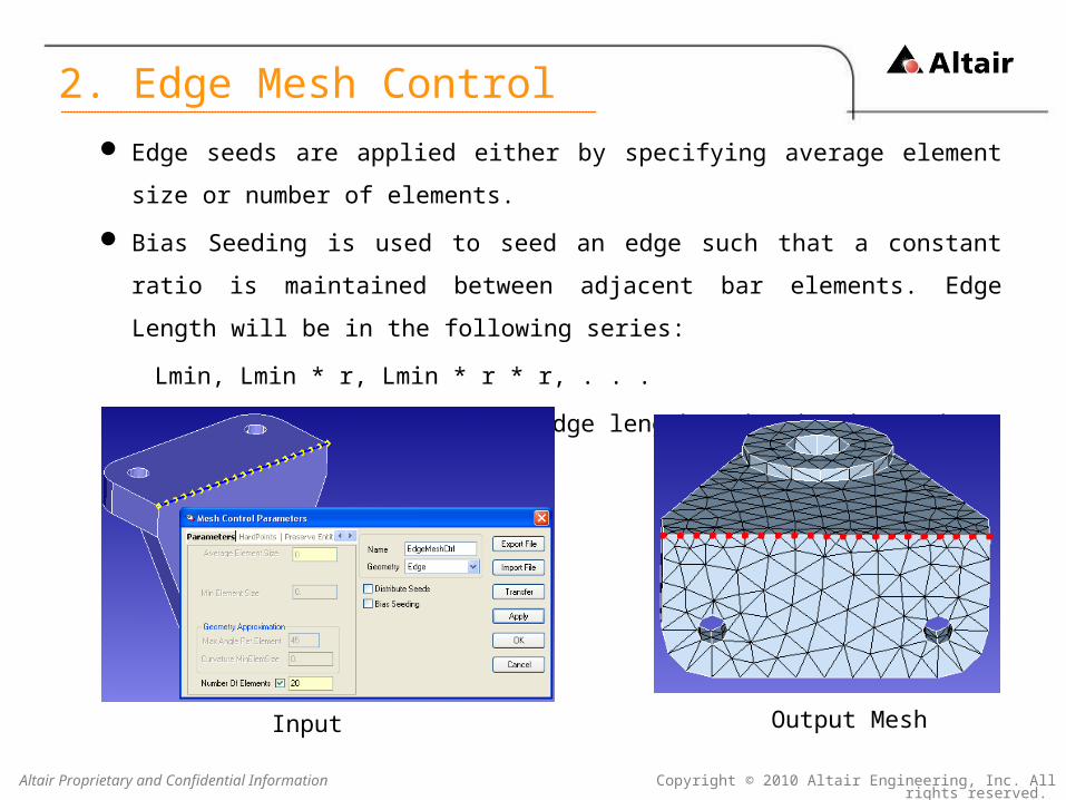
Edge seeds are applied either by specifying average element size or number of
elements.
Bias Seeding is used to seed an edge such that a constant ratio is maintained
between adjacent bar elements. Edge Length will be in the following series:
Lmin, Lmin * r, Lmin * r * r, . . .
where, Lmin is the minimum edge length and r is the ratio.
Input Output Mesh
2. Edge Mesh Control

Copyright © 2010 Altair Engineering, Inc. All rights reserved. Altair Proprietary and Confidential Information
Body Mesh Control is used to control the mesh on selected local bodies.
All entities (faces and edges) present in the body, except the entities with other
local mesh controls, will inherit this mesh control.
Input Output Mesh
3. Body Mesh Control
Copyright © 2010 Altair Engineering, Inc. All rights reserved. Altair Proprietary and Confidential Information
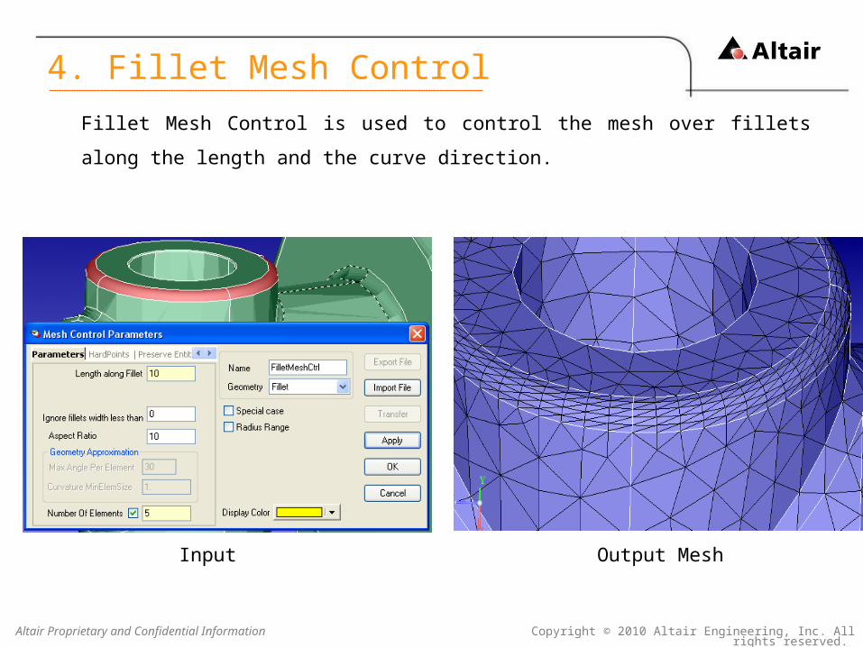
Fillet Mesh Control is used to control the mesh over fillets along the length and the
curve direction.
Input Output Mesh
4. Fillet Mesh Control

Copyright © 2010 Altair Engineering, Inc. All rights reserved. Altair Proprietary and Confidential Information
Cylinder Mesh Control is used to control the mesh both axially and radially on the
selected cylindrical faces.
Input Output Mesh
5. Cylinder Mesh Control

Copyright © 2010 Altair Engineering, Inc. All rights reserved. Altair Proprietary and Confidential Information
Washer mesh control is used to create rings around a circle.
The circle has to be inside one face.
6. Washer Mesh Control
Input Output Mesh
Copyright © 2010 Altair Engineering, Inc. All rights reserved. Altair Proprietary and Confidential Information
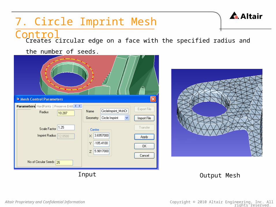
Creates circular edge on a face with the specified radius and the number of seeds.
7. Circle Imprint Mesh Control
Input Output Mesh

Copyright © 2010 Altair Engineering, Inc. All rights reserved. Altair Proprietary and Confidential Information
Region mesh control applies local refinement within the defined shape (Cuboid /
Cylinder) of region.
The selected entities (faces/bodies) that lies inside the region will be assigned the
specified size.
Entities which are partially inside the region will be graded according to region of
overlap.
Also the region can break the face/body along the boundary of the chosen shape
(Cuboid / Cylinder / Plane).
The Plane option is used to Break the body or face.
8. Region Mesh Control

Copyright © 2010 Altair Engineering, Inc. All rights reserved. Altair Proprietary and Confidential Information
Region Mesh Control -Cylinder – Local Size – Without Break
Input
8. Region Mesh Control

Copyright © 2010 Altair Engineering, Inc. All rights reserved. Altair Proprietary and Confidential Information
Region Mesh Control -Cylinder – Local Size – Without Break
Output
8. Region Mesh Control

Copyright © 2010 Altair Engineering, Inc. All rights reserved. Altair Proprietary and Confidential Information
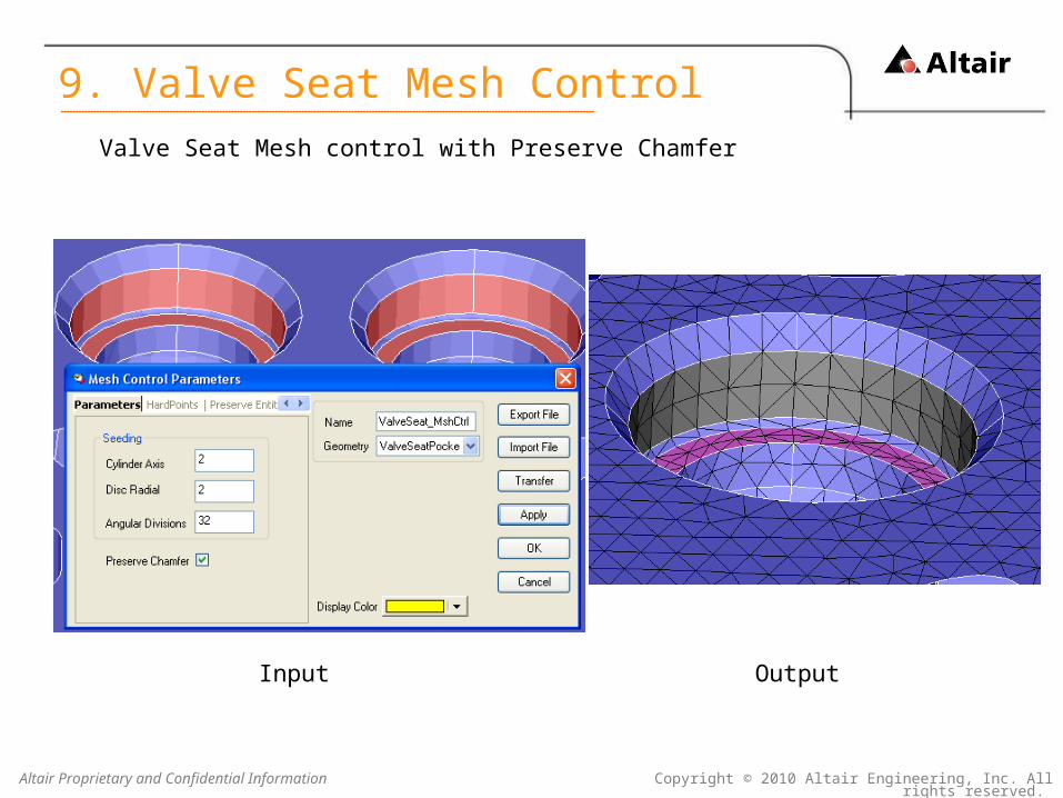
Valve Seat Mesh control is used to control the mesh in the valve seat pocket region.
This controls the mesh on the cylinder and disc faces in the axial and radial direction
and also preserves the chamfer faces if needed.
9. Valve Seat Mesh Control

Copyright © 2010 Altair Engineering, Inc. All rights reserved. Altair Proprietary and Confidential Information
Input
9. Valve Seat Mesh Control
Output
Valve Seat Mesh control without Preserve Chamfer
Copyright © 2010 Altair Engineering, Inc. All rights reserved. Altair Proprietary and Confidential Information
9. Valve Seat Mesh Control
Valve Seat Mesh control with Preserve Chamfer
Input Output
Copyright © 2010 Altair Engineering, Inc. All rights reserved. Altair Proprietary and Confidential Information
Iso-Line Mesh control is used to control the mesh on cylinders and partial
cylinders.
It strictly maintains the axial mesh size and the angle.
This separates iso-line mesh control from fillet and cylinder mesh controls.
Reference point and direction is used to define the start point and the direction of
the isomesh.
Merge option is used to merge the selected faces.
Reference point is also used to generate a mesh such that a radial shift of the iso-
mesh is required.
10. Iso Line Mesh Control

Copyright © 2010 Altair Engineering, Inc. All rights reserved. Altair Proprietary and Confidential Information
Input
10. Iso Line Mesh Control
Output

Copyright © 2010 Altair Engineering, Inc. All rights reserved. Altair Proprietary and Confidential Information
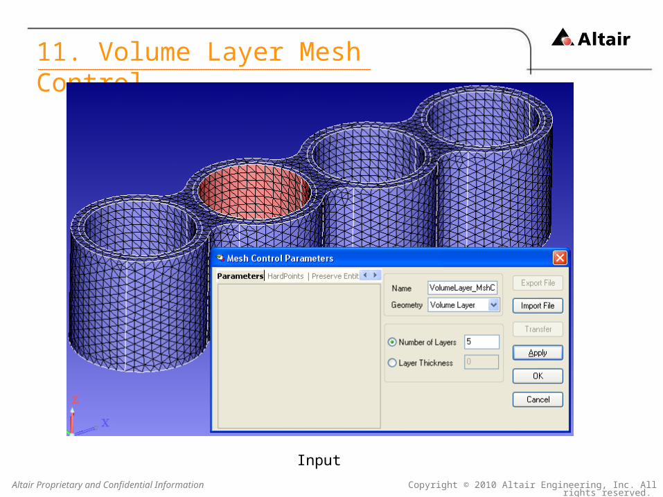
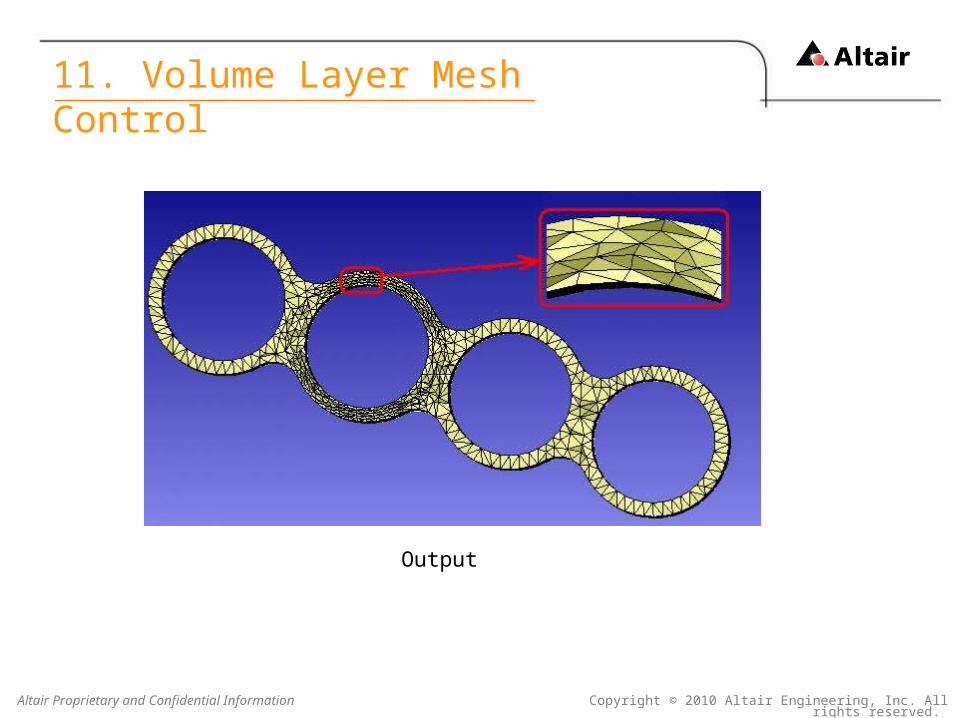
Volume Layer Mesh control is used to generate layers of Tet elements along thin
regions.
The number of layers can also be specified in terms of the thickness of each
layers. This option is useful when the number of layers have to change with the
thickness for a body that has regions of variable thickness.
11. Volume Layer Mesh Control
Copyright © 2010 Altair Engineering, Inc. All rights reserved. Altair Proprietary and Confidential Information
Input
11. Volume Layer Mesh Control
Copyright © 2010 Altair Engineering, Inc. All rights reserved. Altair Proprietary and Confidential Information
Output
11. Volume Layer Mesh Control

Copyright © 2010 Altair Engineering, Inc. All rights reserved. Altair Proprietary and Confidential Information
Hard points are used to create nodes at the specified point location on a face or
an edge during meshing.
Hard Points can be defined by selecting a point on the face/edges. In case of
meshed body we can select nodes as hard point.
Input Output Mesh
Hard Points – Mesh Control

Copyright © 2010 Altair Engineering, Inc. All rights reserved. Altair Proprietary and Confidential Information
The automated meshing process can collapse sliver faces. The mesher will
automatically decide which one to preserve and which one to collapse.
Using Preserve Entities mesh control, the user can control the features to be
preserved while meshing.
There are five types of preserve entities.
Face Shape
Face Edges
Edge
Symmetry Mesh
Mesh
Preserve Entities

Copyright © 2010 Altair Engineering, Inc. All rights reserved. Altair Proprietary and Confidential Information
Face Shape
This option is used to retain the planarity of the face after meshing. The
nodes in the face will not get moved out of the face.
Face Edges
This option is used to retain all the edges of the face after meshing. This
means that tiny edges on the faces will be preserved and the face will not
get collapsed.
Edge
This option is used when only few edges of a face, are to be preserved
when meshing.
Preserve Entities

Copyright © 2010 Altair Engineering, Inc. All rights reserved. Altair Proprietary and Confidential Information
Preserve Entities
Symmetry Mesh
This option is used to get identical mesh between the master face and
symmetry face.
If there are any discontinuous edges, then we need to pick three
nodes/vertices in an order for both master and symmetry face.
Mesh
This option is used to maintain the existing mesh in the face during
meshing.
Copyright © 2010 Altair Engineering, Inc. All rights reserved. Altair Proprietary and Confidential Information
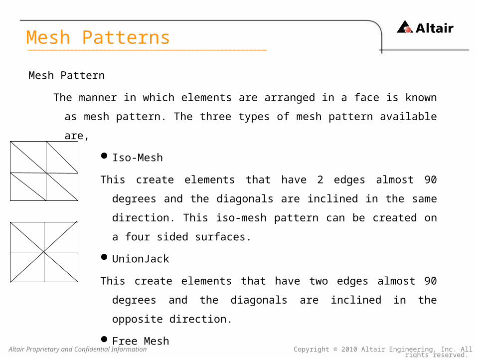
Mesh Pattern
The manner in which elements are arranged in a face is known as mesh pattern.
The three types of mesh pattern available are,
Iso-Mesh
This create elements that have 2 edges almost 90 degrees and the
diagonals are inclined in the same direction. This iso-mesh pattern
can be created on a four sided surfaces.
UnionJack
This create elements that have two edges almost 90 degrees and the
diagonals are inclined in the opposite direction.
Free Mesh
This creates a mesh wherein, the mesh does not follow any pattern.
Mesh Patterns

Copyright © 2010 Altair Engineering, Inc. All rights reserved. Altair Proprietary and Confidential Information
Mesh Patterns

Copyright © 2010 Altair Engineering, Inc. All rights reserved. Altair Proprietary and Confidential Information
Local mesh controls
Select “Mesh Control” in meshing tool bar.
This opens the “Mesh Control Parameters” dialog box.
Select entities and enter values for the mesh control.
Created “Mesh controls” are listed in the “Assembly Model” tree window
under “Process Control” tab.
Local Mesh Controls

Copyright © 2010 Altair Engineering, Inc. All rights reserved. Altair Proprietary and Confidential Information
Whenever, a local mesh control is created, it is listed in the tree view.
By double clicking the mesh control, the “Mesh Control Parameters” dialog box will
open with all values set. These vales can be modified and saved.
Select a face, right click and select “Local Meshing Parameters”. This opens the
mesh control assigned to the selected face. This will work for bodies, faces and
edges.
Modifying Local Mesh Control

Copyright © 2010 Altair Engineering, Inc. All rights reserved. Altair Proprietary and Confidential Information
Exporting a mesh control
The Mesh control created can be saved in an external file, called "Mesh
Specification" and the saved file can be imported back into SimLab. This is very
useful when meshing models of similar types when the mesh control created for
one can be reused for the others.
Mesh Control Specification
Copyright © 2010 Altair Engineering, Inc. All rights reserved. Altair Proprietary and Confidential Information
Exporting a mesh control
This has 4 options,
Template
Mesh control parameters will be stored along with the geometry type
associated with it, (like FACE, EDGE)
Useful for assigning mesh control for models of the same type
Body
Mesh control parameters will be stored along with the entity id.
Useful for re-meshing the same model several times or the same model
with small changes in the CAD file.
Mesh Control Specification

Copyright © 2010 Altair Engineering, Inc. All rights reserved. Altair Proprietary and Confidential Information
Exporting a mesh control
Color
Mesh control parameters will be stored along with the color associated
with it.
Useful for assigning mesh control for models based on color.
Groups
Mesh control parameters will be stored along with the group name
associated with it.
Useful for assigning mesh control for models based on groups.
Mesh Control Specification

Copyright © 2010 Altair Engineering, Inc. All rights reserved. Altair Proprietary and Confidential Information
Importing a mesh control
Select a body to which the mesh control is to be assigned.
Open the “Mesh Control Parameters” dialog box and select “Import File”
Choose the mesh control file (with extension .xml).
This will load all the mesh controls defined in the mesh control file.
Go to the “Mesh Control” dialog box to see the imported mesh controls in the tree
view.
If template mesh spec is used, select bodies, faces, edges or features and assign
it to the mesh control.
Mesh Control Specification

Copyright © 2010 Altair Engineering, Inc. All rights reserved. Altair Proprietary and Confidential Information
It is common to find several cylinders with the same axis but separated by discs,
cones or circular edges.
It is sufficient to assign mesh control to one or part of a circular edge and all the
edges will pick up the mesh seed.
It is sufficient if the axial mesh size if assigned to one cylinder and all cylinders
will pick it up.
This transmission of the mesh size will stop if the circular disk separating the
cylinders is too thick.
Automation