copyright disclaimer trademark recognition federal...
TRANSCRIPT
Preface
PrefaceCopyright
This publication, including all photographs, illustrations and software, is protectedunder international copyright laws, with all rights reserved. Neither this manual, norany of the material contained herein, may be reproduced without written consent ofthe author.
Version 1.0
DisclaimerThe information in this document is subject to change without notice. The manufac-turer makes no representations or warranties with respect to the contents hereof andspecifically disclaims any implied warranties of merchantability or fitness for anyparticular purpose. The manufacturer reserves the right to revise this publication andto make changes from time to time in the content hereof without obligation of themanufacturer to notify any person of such revision or changes.
Federal Communications Commission (FCC)This equipment has been tested and found to comply with the limits for a Class Bdigital device, pursuant to Part 15 of the FCC Rules. These limits are designed toprovide reasonable protection against harmful interference in a residential installa-tion. This equipment generates, uses, and can radiate radio frequency energy and, ifnot installed and used in accordance with the instructions, may cause harmful inter-ference to radio communications. However, there is no guarantee that interferencewill not occur in a particular installation. If this equipment does cause harmfulinterference to radio or television reception, which can be determined by turning theequipment off and on, the user is encouraged to try to correct the interference by oneor more of the following measures:
• Reorient or relocate the receiving antenna.• Increase the separation between the equipment and the receiver.• Connect the equipment onto an outlet on a circuit different from that to
which the receiver is connected.• Consult the dealer or an experienced radio/TV technician for help.
Shielded interconnect cables and a shielded AC power cable must be employed withthis equipment to ensure compliance with the pertinent RF emission limits govern-ing this device. Changes or modifications not expressly approved by the system’smanufacturer could void the user’s authority to operate the equipment.
Trademark RecognitionMicrosoft, MS-DOS and Windows are registered trademarks of Microsoft Corp.
AMD, Phenom, Athlon, Sempron and Duron are registered trademarks of AMDCorporation.
Other product names used in this manual are the properties of their respectiveowners and are acknowledged.

ii
Preface
Declaration of ConformityThis device complies with part 15 of the FCC rules. Operation is subject to thefollowing conditions:
• This device may not cause harmful interference.• This device must accept any interference received, including interfer-
ence that may cause undesired operation.
Canadian Department of CommunicationsThis class B digital apparatus meets all requirements of the Canadian Interference-causing Equipment Regulations.
Cet appareil numérique de la classe B respecte toutes les exigences du Réglement surle matériel brouilieur du Canada.
About the ManualThe manual consists of the following:
Chapter 1
Introducing the Motherboard
Describes features of the motherboard.
Go to page 1
Describes installation of motherboardcomponents.
Go to page 9
Provides information on using the BIOSSetup Utility.
Go to page 27
Describes the motherboard software
Go to page 49
Provides information about SATA RAIDSetup
Go to page 53
Chapter 5Setting Up AMD SB950 RAIDConfiguration
page 65
Chapter 7Trouble Shooting
Provides basic troubleshooting tips
Go to
Chapter 6ATI CrossFireXTM TechnologySupport
Describes the ATI CrossfireTM Technol-ogyGo to page 61
Chapter 2
Installing the Motherboard
Chapter 3
Using BIOS
Chapter 4
Using the Motherboard Software

iii
TTTTTABLE OF CONTENTSABLE OF CONTENTSABLE OF CONTENTSABLE OF CONTENTSABLE OF CONTENTS
Preface i
Chapter 1 1Introducing the Motherboard 1
Introduction............................................................................................1Feature.....................................................................................................2Motherboard Components...................................................................6
Chapter 2 99999
Installing the Motherboard 9 Safety Precautions...............................................................................9
Choosing a Computer Case..................................................................9Installing the Motherboard in a Case.................................................9Checking Jumper Settings..................................................................10
Setting Jumpers.............................................................................10 Checking Jumper Settings................................................................11
Installing Hardware.........................................................................12 Installing the Processor....................................................................12
Installing Memory Modules...........................................................13Expansion Slots.............................................................................15Connecting Optional Devices........................................................17
Installing a Hard Disk Drive/CD-ROM/SATA Hard Drive..........20Connecting I/O Devices......................................................................22Connecting Case Components...........................................................23
Front Panel Header.......................................................................26
Chapter 3 27 27 27 27 27Using BIOS 27 About the Setup Utility.................................................................... 27
The Standard Configuration..........................................................27 Entering the Setup Utilities...........................................................27
Resetting the Default CMOS Values............................................28 Using BIOS........................................................................................29
BIOS Navigation Key....................................................................29 Main Menu...................................................................................30 Advanced Menu............................................................................31
Chipset Menu................................................................................39 M.I.B.X(MB Intelligent Bios X) Menu...........................................40 Boot Menu....................................................................................44 Security Menu...............................................................................45

iv
Chapter 4 49 49 49 49 49Using the Motherboard Software 49
About the Software DVD-ROM/CD-ROM.......................................49Auto-installing under Windows XP/Vista/7.....................................49
Running Setup...............................................................................50 Manual Installation..........................................................................52 Utility Software Reference...............................................................52
Chapter 5 53 53 53 53 53Setting Up AMD SB950 RAID Configuration 53
Setting Up a Bootable RAID Array....................................................53
Chapter 6 61 61 61 61 61ATI CrossFireTM Technology Support 61 Requirements....................................................................................61 Installing CrossFireTM graphics cards............................................61 The CatalystTM Control Center Dialog Box....................................63 To Enable CrossFireTM.................................................................63
Chapter 7 65 65 65 65 65Trouble Shooting 65 Start up problems during assembly.................................................65
Start up problems after prolong use..................................................66 Maintenance and care tips.................................................................66 Basic Troubleshooting Flowchart.....................................................67
Save & Exit Menu.........................................................................46 Updating the BIOS.......................................................................47

1
Introducing the Motherboard
Chapter 1Introducing the Motherboard
IntroductionThank you for choosing the A990FXM-A motherboard. This motherboard is a highperformance, enhanced function motherboard that supports socket for AMDPhenomTM and later desktop processors (socket AM3+) for high-end business orpersonal desktop markets.
There is an advanced full set of I/O ports in the rear panel, including one PS/2 mouseand keyboard combo connector, one Bluetooth, two ESATA ports, one CLR_CMOSbutton, eight USB 2.0 ports, two USB 3.0 ports, two LAN ports, one optical SPDIFOport and audio jacks for microphone, line-in and 8-ch line-out.
The motherboard incorporates the AMD 990FX Northbridge (NB) and SB950Southbridge (SB) chipsets. The Northbridge supports the HyperTransportTM 3.0 in-terface. The memory controller supports DDR3 memory DIMM frequencies of2133 (OC)/1866/1600/1333*1. It supports four DDR3 slots with maximum memorysize of 32 GB*2. Three PCI Express x16 slots, intended for Graphics Interface, arefully compliant to the PCI Express Gen2 (version 2.0). In addition, two PCI Expressx1 slots are supported.
*2. Due to the DRAM maximum size (4 GB per dimm) at present, thememory maximum size we have tested is 8 GB per dimm.
*1. Due to the limitation of AMD CPU spec, please refer to Memory QVLfor more information.
The SB950 Southbridge supports one PCI slot which is PCI v2.3 compliant. Itintegrates USB 2.0 interface, supporting up to twelve USB 2.0 ports (eight USB portsand two USB 2.0 headers support additional four USB 2.0 ports) and one USB 3.0header. The Southbridge integrates a Serial ATA host controller, supporting six SATAports with maximum transfer rate up to 6 Gb/s each, and two eSATA3 6.0 Gb/sconnector at Real connector.
In additon, the mainboard assembles extra USB3.0 chip, which supports two USB 3.0ports at rear panel with high speed of 5Gb/s.

2
FeatureProcessor
HyperTransportTM Technology is a point-to-point link between two devices, itenables integrated circuits to exchange information at much higher speeds thancurrently available interconnect technologies.
• Accommodates AMD PhenomTM and later desktop processors (socketAM3+)
• Supports HyperTransportTM (HT) 3.0 interface speeds
This motherboard uses a socket AM3+ that carries the following features:
SB950 (SB)
AMD 990FX
(NB)
• One x4 A-Link Express III interface for connection toan AMD Southbridge. The A-Link Express III is a propri-etary interface developed by AMD basing on the PCIExpress technology, with additional Northbridge-Southbridge messaging functionalities. It supports thePCIe Gen 2 transfer rate of 5 GT/s, and is backwardcompatible with the A-Link Express II interface.
• Supports three x16 PCI-Express Gen2 graphics link• Fully supports ACPI states S1, S3, S4 and S5• Complies with all relevant Windows Logo Program
(WLP) requirements from Microsoft® for WHQL certifi-cation.
• Supports 16-bit up/down HyperTransport (HT) 3.0 in-terface up to 5.2 GT/s.
The AMD 990FX Northbridge (NB) and SB950 Southbridge (SB) chipsets arebased on an innovative and scalable architecture with proven reliability andperformance.
Chipset
Memory• Supports DDR3 2133 (OC)/1866/1600/1333 DDR3 SDRAM with Dual-
channel architecture• Accommodates four unbuffered DIMMs
• Compliant with PCI 2.3 specification at 33 MHz• Four-lane PCI Express® (PCIe®) 2.0 interface, support-
ing up to two general purpose devices. Supportedconfigurations include: § 1x4 § 2x4 § 1x2+2x1 § 4x1
• Supports six Serial ATA devices which speeds up to 6Gb/s and one IDE ATA133
• Supports two eSATA3 which speeds up to 6.0 Gb/sthrough the bundled eSATA3 bracket
• Integrated USB 3.0 Host Controller supporting up totwo USB 3.0 ports
• Integrated USB 2.0 Host Controller supporting up totwelve USB 2.0 ports
• Supports integrated RAID 0, RAID 1, RAID 5, and RAID10 functionality across all 6 ports (RAID 10 requiresuse of 4 or more SATA ports, and RAID 5 requires useof 3 or more SATA ports)
Introducing the Motherboard

3
Expansion Options
• Three PCI Express x16 slots for Graphics Interface• Two PCI Express x1 slots• One 32-bit PCI v2.3 compliant slot• Six 7-pin SATA connectors• One IDE ATA133 connector
Integrated I/O The motherboard has a full set of I/O ports and connectors:
• One CLR CMOS button• Two ESATA port• One Buletooth• One PS/2 keyboard and mouse combo port• Eight USB 2.0 ports• Two USB 3.0 blue ports• Two LAN ports• One optical SPDIFO port• Audio jacks for microphone, line-in and 8-ch line-out
BIOS Firmware
• Power management• Wake-up alarms• CPU parameters• CPU and memory timing
The firmware can also be used to set parameters for different processor clockspeeds.
The motherboard uses AMI BIOS that enables users to configure many sys-tem features including the following:
1. Some hardware specifications and software items are subject to changewithout prior notice.
2. Due to chipset limitation, we recommend that motherboard be operated inthe ambiance between 0 and 50°C.
Onboard LAN• Supports PCI ExpressTM 2.0• Integrated 10/100/1000 transceiver• Wake-on-LAN and remote wake-up support
Audio• 7.1+2 Channel High Definition Audio Codec• Meets Microsoft WLP3.x (Windows Logo Program) audio require-
ments• All DACs supports 44.1k/48k/96k/192kHz sample rate• Software selectable 2.5V/3.2V/4.0V VREFOUT• Direct Sound 3D. compatible• Power Support: Digital: 3.3V; Analog: 5.0V
The motherboard comes with the following expansion options:
• Up to 8 GB per DIMM with maximum memory size up to 32 GB

4
Introducing the Motherboard
• NB: AMD 990FX SB: SB950
• AMD PhenomTM and later desktop processors (socket AM3+)• Supports HyperTransportTM (HT) 3.0 interface speeds• 140W TDP
• Dual-channel DDR3 memory architecture• 4 x 240-pin DDR3 DIMM sockets support up to 32 GB• Supports DDR3 DDR3 2133 (OC)/1866/1600/1333 SDRAM
• 3 x PCI Express Gen2 x16 slots• 2 x PCI Express x1 slots (Gen2)• 1 x PCI slot• Supported by AMD SB950 Express Chipset
-6 x Serial ATA 6.0 Gb/s Host Controllers-Supports RAID 0, 1, 5 and 10-1 x IDE ATA133
• Supported by Marvell 9128-2 x eSATA 6 Gb/s devices
• ALC892 8-Channel
• Dual Realtek 8111E Giga Lan
• 1 x CLR CMOS button• 2 x eSATA ports• 1 x Buletooth• 1 x PS/2 keyboard and mouse combo port• 8 x USB 2.0 ports• 2 x USB 3.0 blue ports• 2 x RJ45 LAN ports• 1 x Audio port (Line in, microphone in, line out, and optical
SPDIF out)• 1 x 24-pin ATX Power Supply connector• 1 x 8-pin ATX12V connector• 6 x Serial ATA 6Gb/s connectors• 2 x eSATA3 6.0 Gb/s connectors through the bundled eSATA3
bracket• 1 x IDE ATA133 support by Marvell 9128• 2 x USB 2.0 headers support additional 4 USB 2.0 ports• 1 x USB 3.0 header• 1 x Front panel header• 1 x Chassis Intrusion Detect header• 1 x SPDIF out header• 1 x Front panel audio header• 1 x POST Debug LED• 1 x Buzzer• 1 x Reset button• 1 x Power button• 1 x CLR_COMS header• 1 x 4-pin CPU_FAN connector
Chipset
Memory
ExpansionSlots
Storage
Audio
LAN
Rear Panel I/O
Internal I/OConnectors &Headers
CPU
Specifications

5
Introducing the Motherboard
• AMI BIOS with 32Mb SPI Flash ROM• Supports Plug and Play, STR (S3) / STD (S4) , Hardware
monitor, Multi Boot• Supports ACPI & DMI• Audio, LAN, can be disabled in BIOS• F7 hot key for boot up devices option• Supports FSB adjustment, increase in a increase of 1MHz.• Support Over-Clocking• Support Dual Display• Support PgUp clear CMOS Hotkey Has PS2 KB Model only
SystemBIOS
Form Factor • ATX Size, 305mm x 244mm
• 1 x 3-pin SYS_FAN connector• 1 x 3-pin PWR_FAN connector
6
Introducing the Motherboard
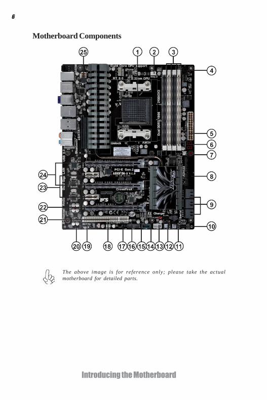
Motherboard Components
The above image is for reference only; please take the actualmotherboard for detailed parts.

7
Introducing the Motherboard
Table of Motherboard Components
This concludes Chapter 1. The next chapter explains how to install the motherboard.
LABEL COMPONENTS
1. CPU Socket AMD PhenomTM and later desktop processors(socket AM3+)
2. CPU_FAN CPU cooling fan connector3. DDR3_1/2/3/4 240-pin DDR3 SDRAM slots4. BZ Buzzer5. ATX_POWER Standard 24-pin ATX power connector6. POST POST Debug LED 7. PWR_FAN Power cooling fan connector8. IDE Primary IDE channel9. SATA1~6 Serial ATA 6.0 Gb/s connectors10. PANEL Front panel switch/LED header11. PWR_BTN Power on button12. RST_BTN Reset button13. F_USB2 Front panel USB 2.0 header14. CLR_CMOS Clear CMOS jumper
15. F_USB1 Front panel USB 2.0 header(with EZ Chargefunction)
16. USB3F Front panel USB 3.0 header17. CASE Case open header18. SYS_FAN System cooling fan connector19. SPDIFO SPDIF out header20. F_AUDIO Front panel audio header21. PCI 32-bit add-on card slot22. PCIEX16_S PCI Express slot for graphics interface23. PCIE1~2 PCI Express x1 slots24. PCIEX16_1~2 PCI Express slots for graphics interface25. ATX12V 8-pin +12V power connector

8
Introducing the Motherboard
Memo

9
Installing the Motherboard
Chapter 2Installing the Motherboard
Safety Precautions• Follow these safety precautions when installing the motherboard• Wear a grounding strap attached to a grounded device to avoid dam-
age from static electricity• Discharge static electricity by touching the metal case of a safely
grounded object before working on the motherboard• Leave components in the static-proof bags they came in• Hold all circuit boards by the edges. Do not bend circuit boards
Choosing a Computer Case
There are many types of computer cases on the market. The motherboard complieswith the specifications for the ATX system case. Some features on the motherboardare implemented by cabling connectors on the motherboard to indicators and switcheson the system case. Make sure that your case supports all the features required. Makesure that your case has sufficient power and space for all drives that you intend toinstall.
Most cases have a choice of I/O templates in the rear panel. Make sure that the I/Otemplate in the case matches the I/O ports installed on the rear edge of themotherboard.
This motherboard carries an ATX form factor of 305 X 244 mm. Choose a case thataccommodates this form factor.
Installing the Motherboard in a CaseRefer to the following illustration and instructions for installing the motherboard ina case.
Most system cases have mounting brackets installed in the case, which correspondthe holes in the motherboard. Place the motherboard over the mounting bracketsand secure the motherboard onto the mounting brackets with screws.
Ensure that your case has an I/O template that supports the I/O ports and expansionslots on your motherboard.

10
Installing the Motherboard
Do not over-tighten the screws as this can stress the motherboard.
Checking Jumper Settings
This section explains how to set jumpers for correct configuration of the motherboard.
Setting JumpersUse the motherboard jumpers to set system configuration options. Jumpers withmore than one pin are numbered. When setting the jumpers, ensure that the jumpercaps are placed on the correct pins.
The illustrations show a 2-pin jumper. Whenthe jumper cap is placed on both pins, thejumper is SHORT. If you remove the jumpercap, or place the jumper cap on just one pin,the jumper is OPEN.
This illustration shows a 3-pin jumper. Pins1 and 2 are SHORT.
SHORT OPEN

11
Installing the Motherboard
Checking Jumper SettingsThe following illustration shows the location of the motherboard jumpers. Pin 1 islabeled.
To avoid the system unstability after clearing CMOS, we recommendusers to enter the main BIOS setting page to “Load Default Settings”and then “Save Changes and Exit”.
Name Type Description Setting (default)
CLR_CMOS 3-pin Clear CMOS
1-2: NORMAL
2-3: CLEARBefore clearing theCMOS, make sure toturn off the system.
CLR_CMOS1 2 3

12
Installing the Motherboard
Installing HardwareInstalling the Processor
Caution: When installing a CPU heatsink and cooling fan make sure thatyou DO NOT scratch the motherboard or any of the surface-mount resis-tors with the clip of the cooling fan. If the clip of the cooling fan scrapesacross the motherboard, you may cause serious damage to the motherboardor its components.
On most motherboards, there are small surface-mount resistors near theprocessor socket, which may be damaged if the cooling fan is carelesslyinstalled.
Avoid using cooling fans with sharp edges on the fan casing and the clips.Also, install the cooling fan in a well-lit work area so that you can clearlysee the motherboard and processor socket.
This motherboard has a socket AM3+ processor socket. When choosing a processor,consider the performance requirements of the system. Performance is based on theprocessor design, the clock speed and system bus frequency of the processor, and thequantity of internal cache memory and external cache memory.
Before installing the Processor
This motherboard automatically determines the CPU clock frequency and systembus frequency for the processor. You may be able to change these settings by makingchanges to jumpers on the motherboard, or changing the settings in the system SetupUtility. We strongly recommend that you do not over-clock processors or othercomponents to run faster than their rated speed.
Warning:
1. Over-clocking components can adversely affect the reliability of thesystem and introduce errors into your system. Over-clocking can perma-nently damage the motherboard by generating excess heat in componentsthat are run beyond the rated limits.
2. Always remove the AC power by unplugging the power cord from thepower outlet before installing or removing the motherboard or other hard-ware components.

13
Installing the Motherboard
1 Install your CPU. Pull up the lever away fromthe socket and lift up to 90-degree angle.
2 Locate the CPU cut edge (the corner withthe pin hold noticeably missing). Align andinsert the CPU correctly.
3 Press the lever down and apply thermalgrease on top of the CPU.
4 Put the CPU Fan down on the retention mod-ule and snap the four retention legs of thecooling fan into place.
5 Flip the levers over to lock the heat sink inplace and connect the CPU cooling Fan powercable to the CPU FAN connector. This com-pletes the installation.
CPU Installation ProcedureThe following illustration shows CPU installation components.
To achieve better airflow rates and heat dissipation, we suggest that youuse a high quality fan with 4800 rpm at least. CPU fan and heatsinkinstallation procedures may vary with the type of CPU fan/heatsink sup-plied. The form and size of fan/heatsink may also vary.
Installing Memory ModulesThis motherboard accommodates four memory modules. It can support four 240-pinDDR3 2133 (OC)/1866/1600/1333. The total memory capacity is 32 GB.
DDR3 SDRAM memory module table
Do not remove any memory module from its antistatic packaging untilyou are ready to install it on the motherboard. Handle the modules onlyby their edges. Do not touch the components or metal parts. Alwayswear a grounding strap when you handle the modules.
You must install at least one module in any of the four slots. Each module can beinstalled with 8 GB of memory.
Memory module Memory Bus
DDR3 1333 667 MHz
1. Due to the limitation of AMD CPU spec, please refer to Memory QVLfor more information.
*
DDR3 1600 800 MHz DDR3 1866 933 MHz DDR3 2133 1067 MHz
* For reference only

14
Installing the Motherboard
Installation ProcedureRefer to the following to install the memory modules.
1 This motherboard supports unbuffered DDR3 SDRAM only.2 Push the latches on each side of the DIMM slot down.3 Align the memory module with the slot. The DIMM slots are keyed with
notches and the DIMMs are keyed with cutouts so that they can only beinstalled correctly.
4 Check that the cutouts on the DIMM module edge connector match thenotches in the DIMM slot.
5 Install the DIMM module into the slot and press it firmly down until itseats correctly. The slot latches are levered upwards and latch on tothe edges of the DIMM.
6 Install any remaining DIMM modules.
For best performance and compatibility, we recommend that users installDIMMs in the sequence of DIMM3, DIMM4, DIMM1 and DIMM2.
* For reference only
15
Installing the Motherboard
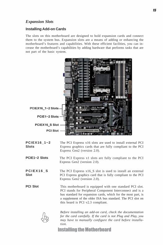
Expansion Slots
Installing Add-on Cards
The slots on this motherboard are designed to hold expansion cards and connectthem to the system bus. Expansion slots are a means of adding or enhancing themotherboard’s features and capabilities. With these efficient facilities, you can in-crease the motherboard’s capabilities by adding hardware that performs tasks that arenot part of the basic system.
P C I E X 1 6 _ SSlot
PCI Slot This motherboard is equipped with one standard PCI slot.PCI stands for Peripheral Component Interconnect and is abus standard for expansion cards, which for the most part, isa supplement of the older ISA bus standard. The PCI slot onthis board is PCI v2.3 compliant.
The PCI Express x1 slots are fully compliant to the PCIExpress Gen2 (version 2.0).
PCIE1~2 Slots
Before installing an add-on card, check the documentationfor the card carefully. If the card is not Plug and Play, youmay have to manually configure the card before installa-tion.
The PCI Express x16_S slot is used to install an externalPCI Express graphics card that is fully compliant to the PCIExpress Gen2 (version 2.0).
The PCI Express x16 slots are used to install external PCIExpress graphics cards that are fully compliant to the PCIExpress Gen2 (version 2.0).
PCIEX16_1~2Slots

16
Installing the Motherboard
Follow these instructions to install an add-on card:
1 Remove a blanking plate from the system case corresponding to theslot you are going to use.
2 Install the edge connector of the add-on card into the expansion slot.Ensure that the edge connector is correctly seated in the slot.
3 Secure the metal bracket of the card to the system case with a screw.
* For reference only
17
Installing the Motherboard
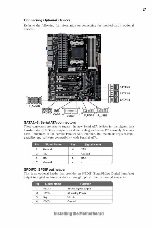
SPDIFO: SPDIF out headerThis is an optional header that provides an S/PDIF (Sony/Philips Digital Interface)output to digital multimedia device through optical fiber or coaxial connector.
Connecting Optional DevicesRefer to the following for information on connecting the motherboard’s optionaldevices:
SATA1~6: Serial ATA connectorsThese connectors are used to support the new Serial ATA devices for the highest datatransfer rates (6.0 Gb/s), simpler disk drive cabling and easier PC assembly. It elimi-nates limitations of the current Parallel ATA interface. But maintains register com-patibility and software compatibility with Parallel ATA.
1 Ground 2 TX+
3 TX- 4 Ground
5 RX- 6 RX+
7 Ground - -
Pin Signal Name Pin Signal Name
2 +5VA 5V analog Power
3 Key No pin
4 GND Ground
Pin Signal Name Function
1 SPDIF SPDIF digital output

18
Installing the Motherboard
F_AUDIO: Front Panel Audio headerThis header allows the user to install auxiliary front-oriented microphone and line-out ports for easier access.
F_USB1~2: Front Panel USB 2.0 headers
The motherboard has six USB ports installed on the rear edge I/O port array. Addi-tionally, some computer cases have USB ports at the front of the case. If you havethis kind of case, use auxiliary USB connector to connect the front-mounted ports tothe motherboard.
Please make sure that the USB cable has the same pin assignment asindicated above. A different pin assignment may cause damage or systemhang-up.
1 USBPWR Front Panel USB Power
2 USBPWR Front Panel USB Power
3 USB_FP_P0- USB Port 0 Negative Signal
4 USB_FP_P1- USB Port 1 Negative Signal
5 USB_FP_P0+ USB Port 0 Positive Signal
6 USB_FP_P1+ USB Port 1 Positive Signal
7 GND Ground
8 GND Ground
9 Key No pin
10 USB_FP_OC0 Overcurrent signal
FunctionPin Signal Name
Pin Signal Name Function1 PORT 1L 2 AUD_GND
3 PORT 1R 4 PRESENCE#
5 PORT 2R 6 SENSE1_RETURN
7 SENSE_SEND 8 KEY
Pin Signal Name
9 PORT 2L 10 SENSE2_RETURN
Pin Signal Name
CASE: Chassis Intrusion Detect Header
Short Chassis cover is removed
Open Chassis cover is closed
Pin 1-2 Function
This detects if the chassis cover has been removed. This function needs a chassisequipped with instrusion detection switch and needs to be enabled in BIOS.
Unlike F_USB2 in this mainboard, F_USB1 supports EZ Charger technology (op-tional), provides 3 times current than general USB port in off mode for USB devices.It is useful and excellent, especially for the iPhone, iPad and iPod touch devices thatneed a large amount of current for faster recharging within less time.

19
Installing the Motherboard
1 Vbus Front Panel USB Power
2 IntA_P1_SSRX- USB3 ICC Port1 SuperSpeed Rx-
3 IntA_P2_SSRX+ USB3 ICC Port1 SuperSpeed Rx+
4 GND GND
5 IntA_P1_SSTX- USB3 ICC Port1 SuperSpeed Tx-
6 IntA_P1_SSTX+ USB3 ICC Port1 SuperSpeed Tx+
7 GND GND
8 IntA_P1_D- USB3 ICC Port1 D-
9 IntA_P1_D+ USB3 ICC Port1 D+
10 ID USBOC- Over Current Protection
Pin Signal Name Function
USB3F: Front Panel USB 3.0 headerThis Motherboard implements one USB 3.0 header supporting 2 extra front USB 3.0ports, which delivers 5Gb/s transfer rate.
11 IntA_P2_D+ USB3 ICC Port2 D+
12 IntA_P2_D- USB3 ICC Port2 D-
13 GND GND
Please make sure that the USB cable has the same pin assignment asindicated above. A different pin assignment may cause damage or systemhang-up.
15 IntA_P2_SSTX- USB3 ICC Port2 SuperSpeed Tx-
16 GND GND
17 IntA_P2_SSRX+ USB3 ICC Port2 SuperSpeed Rx+
18 IntA_P2_SSRX- USB3 ICC Port2 SuperSpeed Rx-
19 Vbus Front Panel USB Power
14 IntA_P2_SSTX+ USB3 ICC Port2 SuperSpeed Tx+

20
Installing the Motherboard
About SATA ConnectorsYour motherboard features six SATA connectors supporting a total of six drives.SATA refers to Serial ATA (Advanced Technology Attachment) is the standard inter-face for the IDE hard drives which are currently used in most PCs. These connectorsare well designed and will only fit in one orientation. Locate the SATA connectors onthe motherboard and follow the illustration below to install the SATA hard drives.
Installing Serial ATA Hard DrivessTo install the Serial ATA (SATA) hard drives, use the SATA cable that supports theSerial ATA protocol. This SATA cable comes with an SATA power cable. You canconnect either end of the SATA cable to the SATA hard drive or the connector on themotherboard.
SATA cable (optional) SATA power cable (optional)
Installing a Hard Disk Drive/CD-ROM/SATA Hard DriveThis section describes how to install IDE devices such as a hard disk drive and a CD-ROM drive.
About IDE DevicesYour motherboard has one IDE interface. An IDE ribbon cable supporting two IDEdevices is bundled with the motherboard.
You must orient the cable connector so that the pin1 (color) edge of thecable corresponds to the pin 1 of the I/O port connector.
IDE devices enclose jumpers or switches used to set the IDE device as MASTER orSLAVE. Refer to the IDE device user’s manual. Installing two IDE devices on onecable, ensure that one device is set to MASTER and the other device is set to SLAVE.The documentation of your IDE device explains how to do this.
IDE: IDE ConnectorThis motherboard supports six high data transfer SATA ports with each runs up to 3.0Gb/s. To get better system performance, we recommend users connect the CD-ROMto the IDE channel, and set up the hard drives on the SATA ports.

21
Installing the Motherboard
Refer to the illustration below for proper installation:
This motherboard supports the “Hot-Plug” function.
1 Attach either cable end to the connector on the motherboard.2 Attach the other cable end to the SATA hard drive.3 Attach the SATA power cable to the SATA hard drive and connect the
other end to the power supply.
* For reference only

22
Installing the Motherboard
Connecting I/O DevicesThe backplane of the motherboard has the following I/O ports:
USB 3.0 Ports Use the USB 3.0 ports to connect USB3.0 devices.
LAN Ports Connect an RJ-45 jack to the LAN port to connect your computer to the network.
Bluetooth Used to connect to Bluetooth devices.
eSATA Ports Use these ports to connect to external SATA boxes or SerialATA port multipliers.Before connecting the eSATA cables, make sure to turn offthe power of the external enclosure.
PS/2 mouse andkeyboard comboconnector
CLR_COMS_BTN Use the CLR_CMOS button to clear CMOS.
Audio Ports Use the audio jacks to connect audio devices. The C port isfor stereo line-in signal, while the E port is for microphonein signal. This motherboard supports audio devices that cor-respond to the A, B and D port respectively. In addition, allof the 3 ports, B, and D provide users with both right & leftchannels individually. Users please refer to the followingnote for specific port function definition.
This jack connects to external optical digital audio outputdevices.
Optical SPDIFOutput
The above port definition can be changed to audio input oraudio output by changing the driver utility setting.
A: Center & Woofer D: Front Out B: Back Surround E: Mic_in Rear C: Line-in -
Connect the PS/2 Keyboard or PS/2 Mouse to the PS/2combo port.
USB 2.0 Ports Use the USB 2.0 ports to connect USB 2.0 devices.

23
Installing the Motherboard
Connecting Case ComponentsAfter you have installed the motherboard into a case, you can begin connecting themotherboard components. Refer to the following:
1 Connect the CPU cooling fan cable to CPU_FAN.2 Connect the standard power supply connector to ATX_POWER.3 Connect the case switches and indicator LEDs to the PANEL.4 Connect the system cooling fan connector to SYS_FAN.5 Connect the auxiliary case power supply connector to ATX12V.6 Connect the power cooling fan connector to PWR_FAN.
Users please note that the 24-pin power cable can be connected to theATX_POWER connector.
With ATX v2.x power supply, users pleasenote that when installing 24-pin powercable, the latches of power cable and theATX_POWER match perfectly.
Connecting 24-pin power cable
24-pin power cable * For reference only

24
Installing the Motherboard
CPU_FAN: Cooling FAN Power Connector
Users please note that the fan connector supports the CPU coolingfan of 1.1A~2.2A (26.4W max.) at +12V.
1 GND System Ground
2 +12V Power +12V
3 Sense Sensor
4 PWM CPU FAN control
FunctionPin Signal Name
ATX_POWER: ATX 24-pin Power Connector
1 +3.3V 13 +3.3V
2 +3.3V 14 -12V
3 Ground 15 COM
4 +5V 16 PS_ON
5 Ground 17 COM
6 +5V 18 COM
7 Ground 19 COM
8 PWRGD 20 -5V
9 +5VSB 21 +5V
10 +12V 22 +5V
11 +12V 23 +5V
12 +3.3V 24 COM
Pin Signal Name Pin Signal Name
When installing 4-pin power cable, thelatch falls on the left side of theATX12V connector.
4-pin power cable
Users please note that the 8-pin and 4-pin power cables can both be con-nected to the ATX12V connector.
When installing 8-pin power cable, thelatches of power cable and the ATX12Vconnector match perfectly.
Connecting 8/4-pin power cable
8-pin power cable
* For reference only
* For reference only
25
Installing the Motherboard
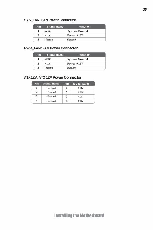
SYS_FAN: FAN Power Connector
Pin Signal Name Function1 GND System Ground2 +12V Power +12V3 Sense Sensor
ATX12V: ATX 12V Power ConnectorPin Signal Name
4 Ground
3 Ground
2 Ground
1 Ground
Pin Signal Name5 +12V
6 +12V
7 +12V
8 +12V
PWR_FAN: FAN Power Connector
Pin Signal Name Function1 GND System Ground2 +12V Power +12V3 Sense Sensor

26
Installing the Motherboard
Reset Switch
Supporting the reset function requires connecting pin 5 and 7 to a momentary-contact switch that is normally open. When the switch is closed, the board resets andruns POST.
Power SwitchSupporting the power on/off function requires connecting pins 6 and 8 to a momen-tary-contact switch that is normally open. The switch should maintain contact for atleast 50 ms to signal the power supply to switch on or off. The time requirement isdue to internal de-bounce circuitry. After receiving a power on/off signal, at least twoseconds elapses before the power supply recognizes another on/off signal.
This concludes Chapter 2. The next chapter covers the BIOS.
Front Panel HeaderThe front panel header (F_PANEL) provides a standard set of switch and LED headerscommonly found on ATX or Micro ATX cases. Refer to the table below for informa-tion:
Power/Sleep/Message waiting LED
Connecting pins 2 and 4 to a single or dual-color, front panel mounted LED providespower on/off, sleep, and message waiting indication.
Hard Drive Activity LED
Connecting pins 1 and 3 to a front panel mounted LED provides visual indication thatdata is being read from or written to the hard drive. For the LED to function properly,an IDE drive should be connected to the onboard IDE interface. The LED will alsoshow activity for devices connected to the SCSI (hard drive activity LED) connector.
Pin Signal Function Pin Signal Function1 HD_LED_P Hard disk LED (+) 2 FP PWR/SLP *MSG LED (+)
3 HD_LED_N Hard disk LED (-)
5 RST_SW_N Reset Switch (-)
7 RST_SW_P Reset Switch (+)
9 RSVD Reserved
4 FP PWR/SLP *MSG LED (-)
6 PWR_SW_P Power Switch (+)
8 PWR_SW_N Power Switch (-)
10 Key No pin
* MSG LED (dual color or single color)

27
Using BIOS
Chapter 3
Using BIOS
About the Setup UtilityThe computer uses the latest “American Megatrends Inc. ” BIOS with support forWindows Plug and Play. The CMOS chip on the motherboard contains the ROMsetup instructions for configuring the motherboard BIOS.
The BIOS (Basic Input and Output System) Setup Utility displays the system’sconfiguration status and provides you with options to set system parameters. Theparameters are stored in battery-backed-up CMOS RAM that saves this informationwhen the power is turned off. When the system is turned back on, the system isconfigured with the values you stored in CMOS.
The BIOS Setup Utility enables you to configure:
• Hard drives, diskette drives and peripherals• Video display type and display options• Password protection from unauthorized use• Power Management features
The settings made in the Setup Utility affect how the computer performs. Beforeusing the Setup Utility, ensure that you understand the Setup Utility options.
This chapter provides explanations for Setup Utility options.
The Standard ConfigurationA standard configuration has already been set in the Setup Utility. However, werecommend that you read this chapter in case you need to make any changes in thefuture.
This Setup Utility should be used:• when changing the system configuration• when a configuration error is detected and you are prompted to make
changes to the Setup Utility• when trying to resolve IRQ conflicts• when making changes to the Power Management configuration• when changing the password or making other changes to the Security
Setup
Entering the Setup UtilityWhen you power on the system, BIOS enters the Power-On Self Test (POST)routines. POST is a series of built-in diagnostics performed by the BIOS. After thePOST routines are completed, the following message appears:Press DEL to enter SETUP

28
Using BIOS
Press the delete key to access the BIOS Setup Utility.
Resetting the Default CMOS ValuesWhen powering on for the first time, the POST screen may show a “CMOSSettings Wrong” message. This standard message will appear following a clearCMOS data at factory by the manufacturer. You simply need to Load DefaultSettings to reset the default CMOS values. Note: Changes to system hardware such as different CPU, memories, etc. may alsotrigger this message.
BIOS Information
System Date [ Mon 04/18/2011]System Time [05:44:29]
Choose the system defaultlanguage
Aptio Setup Utility - Copyright (C) 2010 American Megatrends, Inc.
Version 2.10.1208. Copyright (C) 2010 American Megatrends, Inc.
Main Advanced Chipset M.I.B X Boot Security Save & Exit
+/- : Change Opt.Enter : Select
F1:General Help
:Select Screen:Select Item
F2:Previous Value F3:Optimized Defaults
F4:Save & Exit ESC:Exit

29
Using BIOS
BIOS Navigation KeysThe BIOS navigation keys are listed below:
Using BIOSWhen you start the Setup Utility, the main menu appears. The main menu of theSetup Utility displays a list of the options that are available. A highlight indicateswhich option is currently selected. Use the cursor arrow keys to move the highlightto other options. When an option is highlighted, execute the option by pressing<Enter>.
Some options lead to pop-up dialog boxes that prompt you to verify that you wish toexecute that option. Other options lead to dialog boxes that prompt you for infor-mation.
Some options (marked with a triangle ) lead to submenus that enable you to changethe values for the option. Use the cursor arrow keys to scroll through the items in thesubmenu.
In this manual, default values are enclosed in parenthesis. Submenu items are denotedby a triangle .
The default BIOS setting for this motherboard applies for most conditionswith optimum performance. It is not suggested to change the defaultvalues in the BIOS setup and the manufacture takes no responsibility toany damage caused by changing the BIOS settings.
KEY FUNCTION
Select Item +/- Change opt.
F2 Previous Value
F3 Optimized Defaults
F1 General Help
ESC Exits the current menu
Enter Select
F4 Save & Exit
Select Screen
For the purpose of better product maintenance, the manufacture reservesthe right to change the BIOS items presented in this manual. The BIOSsetup screens shown in this chapter are for reference only and may differfrom the actual BIOS. Please visit the manufacture’s website for updatedmanual.

30
Using BIOS
When you enter the BIOS Setup program, the main menu appears, giving you anoverview of the basic system information. Select an item and press <Enter> todisplay the submenu.
Main Menu
Date & TimeThe Date and Time items show the current date and time on the computer. If you arerunning a Windows OS, these items are automatically updated whenever you makechanges to the Windows Date and Time Properties utility.
BIOS Information
System Date [ Mon 04/18/2011]System Time [05:44:29]
Choose the system default
Aptio Setup Utility - Copyright (C) 2010 American Megatrends, Inc.
Version 2.10.1208. Copyright (C) 2010 American Megatrends, Inc.
Main Advanced Chipset M.I.B X Boot Security Save & Exit
+/- : Change Opt.Enter : Select
F1:General Help
:Select Screen:Select Item
F2:Previous Value F3:Optimized Defaults
F4:Save & Exit ESC:Exit

31
Using BIOS
The Advanced menu items allow you to change the settings for the CPU andother system.
Advaned Menu
LAN ConfigurationThe item in the menu shows the LAN-related information that the BIOSautomatically detects.
Launch PXE OpROM (Disabled)Use this item to enable or disable the PXE OpROM.
Launch Storage OpROM (Enabled)Use this item to enable or disable the Storage OpROM.
LAN Configuration
Onboard LAN 1 Controller [Enabled]Onboard LAN 1 Controller [Enabled]
Enable/Disable Onboard LAN 1Controller
Aptio Setup Utility - Copyright (C) 2010 American Megatrends, Inc.
Version 2.10.1208. Copyright (C) 2010 American Megatrends, Inc.
Main Advanced Chipset M.I.B X Boot Security Save & Exit
+/- : Change Opt.Enter : Select
F1:General Help
:Select Screen:Select Item
F2:Previous Value F3:Optimized Defaults
F4:Save & Exit ESC:Exit
Onboard LAN1/2 Controller (Enabled)Use this item to enable or disable the Onboard LAN.
Press <Esc> to return to the Advanced Menu page.
Legacy OpROM SupportLaunch PXE OpROM [Disabled]Launch Storage OpROM [Enabled]
Enable or Disable Boot Optionfor Leagacy Network Devices.
Aptio Setup Utility - Copyright (C) 2010 American Megatrends, Inc.
Version 2.10.1208. Copyright (C) 2010 American Megatrends, Inc.
Main Advanced Chipset M.I.B X Boot Security Save & Exit
+/- : Change Opt.Enter : Select
F1:General Help
:Select Screen:Select Item
F2:Previous Value F3:Optimized Defaults
F4:Save & Exit ESC:Exit
LAN ConfigurationPC Health StatusPower Management SetupACPI SettingsCPU ConfigurationSATA ConfigurationUSB Configuration

32
Using BIOS
PC Health StatusOn motherboards support hardware monitoring, this item lets you monitor thepaeameters for critical voltages, temperatures and fan speeds.
CPU/System Smart FAN Control (Enabled)This item allows you to enable/disable the control of the CPU/system fan speed bychang-ing the fan voltage.
Smart Fan FunctionScroll to this item and press <Enter> to view the following screen:
CPU Smart Fan Control [Enabled]Smart Fan Mode [Normal]
SMART Fan start PWM value 56SMART Fan start PWM TEMP 27Delta T +3SMART Fan Slope PWM value 6 PWM value/uniteCPU Fan Full Speed Offset (-) 60
System Smart Fan Control [Enabled]Smart Fan Mode [Normal]
SMART Fan start PWM value 56SMART Fan start PWM TEMP 27Delta T +3SMART Fan Slope PWM value 6 PWM value/uniteSystem Fan Full Speed Offset (-) 60
Aptio Setup Utility - Copyright (C) 2010 American Megatrends, Inc.
Version 2.10.1208. Copyright (C) 2010 American Megatrends, Inc.
Main Advanced Chipset M.I.B X Boot Security Save & Exit
+/- : Change Opt.Enter : Select
F1:General Help
:Select Screen:Select Item
F2:Previous Value F3:Optimized Defaults
F4:Save & Exit ESC:Exit
PC Health Status
Smart Fan FunctionCPU Tcontrol : +58 °CCPU Fan Speed : 3000 RPMSystem Fan Speed : N/ACPU Vcore : +1.452VDIMM Voltage : +1.572VNB Voltage : +1.116V
Aptio Setup Utility - Copyright (C) 2010 American Megatrends, Inc.
Version 2.10.1208. Copyright (C) 2010 American Megatrends, Inc.
Main Advanced Chipset M.I.B X Boot Security Save & Exit
+/- : Change Opt.Enter : Select
F1:General Help
:Select Screen:Select Item
F2:Previous Value F3:Optimized Defaults
F4:Save & Exit ESC:Exit

33
Using BIOS
• CPU Tcontrol • CPU FAN Speed • System FAN Speed • CPU Vcore • DIMM Voltage • NB Voltage
System Component CharacteristicsThese items display the monitoring of the overall inboard hardware healthevents, such as System & CPU temperature, CPU & DIMM voltage, CPU &system fan speed,... etc.
Smart Fan Mode (Normal)This item allows you to select the fan mode (Normal, Quiet, Silent, or Manual) for abetter operation environment. If you choose Normal mode, the fan speed will beauto adjusted depending on the CPU temperature. If you choose Quite mode, the fanspeed will be auto minimized for quiet environment. If you choose Silent mode, thefan speed will be auto restricted to make system more quietly. If you choose Manualmode, the fan speed will be adjust depending on users’ parameters.
SMART Fan start PWM value (56)
SMART Fan start TEMP (27)This item is used to set the start PWM value of the smart fan.
This item is used to set the start temperature of the smart fan.
DeltaT (+3)This item specifies the range that controls CPU temperature and keeps it from goingso high or so low when smart fan works.
SMART Fan Slope PWM value (6 PWM value/unite)This item is used to set the Slope Select PWM of the smart fan.
This item is used to set the CPU/system fan full speed offset value.CPU/System Fan Full Speed Offset(-) (60)
Press <Esc> to return to the PC Health Status page.
34
Using BIOS
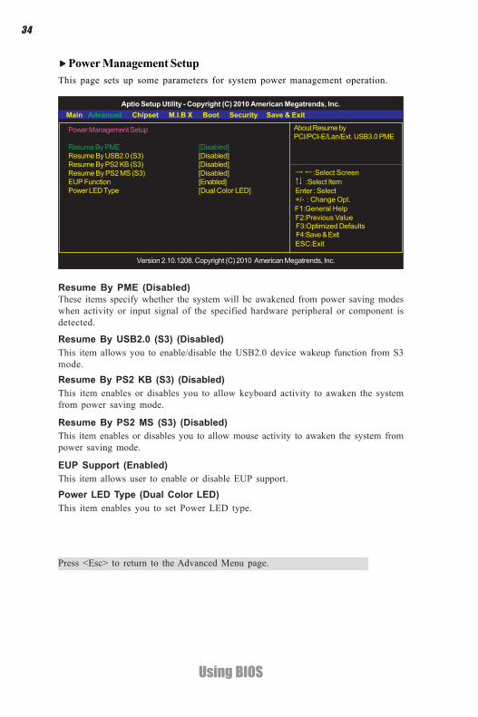
Power Management SetupThis page sets up some parameters for system power management operation.
Resume By PME (Disabled)These items specify whether the system will be awakened from power saving modeswhen activity or input signal of the specified hardware peripheral or component isdetected.
Power LED Type (Dual Color LED)This item enables you to set Power LED type.
Resume By USB2.0 (S3) (Disabled)This item allows you to enable/disable the USB2.0 device wakeup function from S3mode.
Power Management Setup
Resume By PME [Disabled]Resume By USB2.0 (S3) [Disabled]Resume By PS2 KB (S3) [Disabled]Resume By PS2 MS (S3) [Disabled]EUP Function [Enabled]Power LED Type [Dual Color LED]
Aptio Setup Utility - Copyright (C) 2010 American Megatrends, Inc.
Version 2.10.1208. Copyright (C) 2010 American Megatrends, Inc.
Main Advanced Chipset M.I.B X Boot Security Save & Exit
+/- : Change Opt.Enter : Select
F1:General Help
:Select Screen:Select Item
F2:Previous Value F3:Optimized Defaults
F4:Save & Exit ESC:Exit
About Resume byPCI/PCI-E/Lan/Ext. USB3.0 PME
EUP Support (Enabled)This item allows user to enable or disable EUP support.
Resume By PS2 MS (S3) (Disabled)This item enables or disables you to allow mouse activity to awaken the system frompower saving mode.
Resume By PS2 KB (S3) (Disabled)This item enables or disables you to allow keyboard activity to awaken the systemfrom power saving mode.
Press <Esc> to return to the Advanced Menu page.
35
Using BIOS
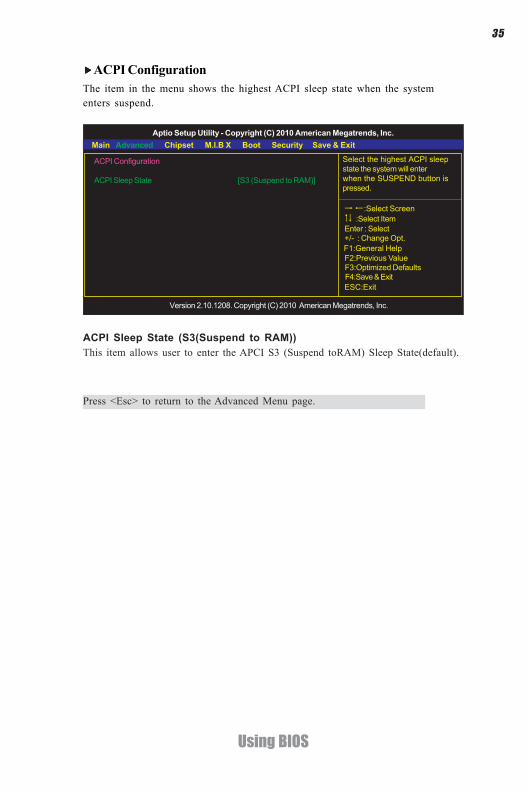
ACPI ConfigurationThe item in the menu shows the highest ACPI sleep state when the systementers suspend.
ACPI Sleep State (S3(Suspend to RAM))This item allows user to enter the APCI S3 (Suspend toRAM) Sleep State(default).
Press <Esc> to return to the Advanced Menu page.
ACPI Configuration
ACPI Sleep State [S3 (Suspend to RAM)]
Aptio Setup Utility - Copyright (C) 2010 American Megatrends, Inc.
Version 2.10.1208. Copyright (C) 2010 American Megatrends, Inc.
Main Advanced Chipset M.I.B X Boot Security Save & Exit
+/- : Change Opt.Enter : Select
F1:General Help
:Select Screen:Select Item
F2:Previous Value F3:Optimized Defaults
F4:Save & Exit ESC:Exit
Select the highest ACPI sleepstate the system will enterwhen the SUSPEND button ispressed.
36
Using BIOS
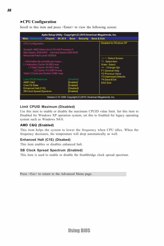
CPU ConfigurationScroll to this item and press <Enter> to view the following screen:
CPU Configuration
Socket0: AMD Athlon (tm) II X3 440 Processor 0Max Speed: 3000 MHZ Intended Speed:3000 MHZMicrocode Patch Level:10000c6
-- Information de cachette par noyau --L1 Instruction Cache: 64 KB/2-way L1 Data Cache: 64 KB/2-way L2 Cache: 512 KB/16-wayTotal L3 Cache per Socket: 0 MB/~way
Limit CPUID Maximum [Disabled]AMD C&Q [Enabled]Core C6 State [Enabled]Enhanced Halt (C1E) [Disabled]SB Clock Spread Spectrum [Enabled]
Aptio Setup Utility - Copyright (C) 2010 American Megatrends, Inc.
Version 2.10.1208. Copyright (C) 2010 American Megatrends, Inc.
Main Advanced Chipset M.I.B X Boot Security Save & Exit
+/- : Change Opt.Enter : Select
F1:General Help
:Select Screen:Select Item
F2:Previous Value F3:Optimized Defaults
F4:Save & Exit ESC:Exit
Disabled for Windows XP
AMD C&Q (Enabled)This item helps the system to lower the frequency when CPU idles. When thefrequency decreases, the temperature will drop automatically as well.
Enhanced Halt (C1E) (Disabed)This item enables or disables enhanced halt.
Limit CPUID Maximum (Disabled)Use this item to enable or disable the maximum CPUID value limit. Set this item toDisabled for Windows XP operation system; set this to Enabled for legacy operatingsystem such as Windows N4.0.
SB Clock Spread Spectrum (Enabled)This item is used to enable or disable the Southbridge clock spread spectrum.
Press <Esc> to return to the Advanced Menu page.
37
Using BIOS
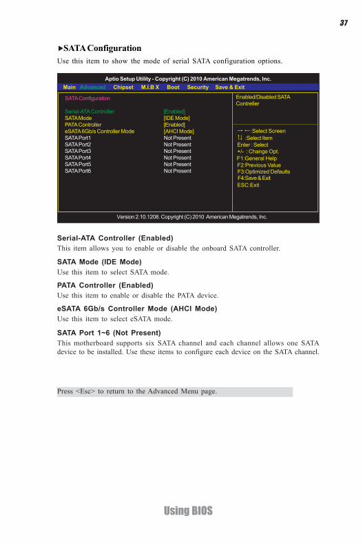
SATA ConfigurationUse this item to show the mode of serial SATA configuration options.
Serial-ATA Controller (Enabled)This item allows you to enable or disable the onboard SATA controller.
SATA Mode (IDE Mode)Use this item to select SATA mode.
SATA Port 1~6 (Not Present)This motherboard supports six SATA channel and each channel allows one SATAdevice to be installed. Use these items to configure each device on the SATA channel.
Press <Esc> to return to the Advanced Menu page.
SATA Configuration
Serial-ATA Controller [Enabled]SATA Mode [IDE Mode]PATA Controller [Enabled]eSATA 6Gb/s Controller Mode [AHCI Mode]SATA Port1 Not PresentSATA Port2 Not PresentSATA Port3 Not PresentSATA Port4 Not PresentSATA Port5 Not PresentSATA Port6 Not Present
Aptio Setup Utility - Copyright (C) 2010 American Megatrends, Inc.
Version 2.10.1208. Copyright (C) 2010 American Megatrends, Inc.
Main Advanced Chipset M.I.B X Boot Security Save & Exit
+/- : Change Opt.Enter : Select
F1:General Help
:Select Screen:Select Item
F2:Previous Value F3:Optimized Defaults
F4:Save & Exit ESC:Exit
Enabled/Disabled SATAContreller
eSATA 6Gb/s Controller Mode (AHCI Mode)Use this item to select eSATA mode.
PATA Controller (Enabled)Use this item to enable or disable the PATA device.

38
Using BIOS
USB ConfigurationScroll to this item and press <Enter> to view the following screen:
All USB Devices (Enabled)Use this item to enable or disable all USB devices.
USB 3.0 Support (Enabled)Use this item to enable or disable USB 3.0 controller. We recommand users keep thedefault value. Disabling it might cause the USB devices not to work properly.
Legacy USB Support (Enabled)Use this item to enable or disable support for legacy USB devices. Setting toAudioallows the system to detect the presence of the USB device at startup. If detected, theUSB controller legacy mode is enabled. If no USB device is detected, the legacy USBsupport is disabled.
Press <Esc> to return to the Advanced Menu page.
USB Configuration
All USB Devices [Enabled]USB 3.0 Support [Enabled]Legacy USB Support [Enabled]Bluetooth Function [Enabled]
Aptio Setup Utility - Copyright (C) 2010 American Megatrends, Inc.
Version 2.10.1208. Copyright (C) 2010 American Megatrends, Inc.
Main Advanced Chipset M.I.B X Boot Security Save & Exit
+/- : Change Opt.Enter : Select
F1:General Help
:Select Screen:Select Item
F2:Previous Value F3:Optimized Defaults
F4:Save & Exit ESC:Exit
Enabled/Disabled All USBDevices
Bluetooth Function (Enabled)Use this item to enable or disable bluetooth function.

39
Using BIOS
South Bridge
Restore AC Power Loss [Power Off]
Audio ConfigurationAzalia HD Audio [Enabled]
Aptio Setup Utility - Copyright (C) 2010 American Megatrends, Inc.
Version 2.10.1208. Copyright (C) 2010 American Megatrends, Inc.
Main Advanced Chipset M.I.B X Boot Security Save & Exit
+/- : Change Opt.Enter : Select
F1:General Help
:Select Screen:Select Item
F2:Previous Value F3:Optimized Defaults
F4:Save & Exit ESC:Exit
Specify what state to go towhen power is re-applied aftera power failure (G3 state).
The chipset menu items allow you to change the settings for the South chipset andother system.
Chipset Menu
South BridgeScroll to this item and press <Enter> and view the following screen:
South Bridge
Aptio Setup Utility - Copyright (C) 2010 American Megatrends, Inc.
Version 2.10.1208. Copyright (C) 2010 American Megatrends, Inc.
Main Advanced Chipset M.I.B X Boot Security Save & Exit
+/- : Change Opt.Enter : Select
F1:General Help
:Select Screen:Select Item
F2:Previous Value F3:Optimized Defaults
F4:Save & Exit ESC:Exit
South Bridge Parameters
Restore AC Power Loss (Power Off)This item enables your computer to automatically restart or return to its operatingstatus.Audio ConfigurationThis item shows the information of the audio configuration.
Azalia HD Audio (Enabled)This item enables or disables Azalia HD audio.

40
Using BIOS
M.I.B X (MB Intelligent BIOS X)
Peocessor Power Planes and Voltage ControlsMemory ControlHT Control
Auto Detect DIMM/PCI Clk [Enabled]CPU/HT Reference Clock (MHz) 200CPU Unclock [Disabled]CPU Voltage [Default]NB Voltage [Default]VDIMM Voltage [Default]SB Voltage [Default]CPU Current Voltage 1.452VDIMM Current Voltage 1.572NB Current Voltage 1.116
Aptio Setup Utility - Copyright (C) 2010 American Megatrends, Inc.
Version 2.10.1208. Copyright (C) 2010 American Megatrends, Inc.
Main Advanced Chipset M.I.B X Boot Security Save & Exit
+/- : Change Opt.Enter : Select
F1:General Help
:Select Screen:Select Item
F2:Previous Value F3:Optimized Defaults
F4:Save & Exit ESC:Exit
Peocessor Power Planes andVoltage Controls
Current CPU Speed (2500 MHz)This item shows current CPU speed.
M.I.B X(MB Intelligent BIOS X)This page enables you to set the clock speed and system bus for your system. Theclock speed and system bus are determined by the kind of processor you have in-stalled in your system.
Peocessor Power Planes and Voltage ControlsScroll to this item and press <Enter> to view the following screen:
Peocessor Power Planes and Voltage Controls
Current CPU Speed 2500MHzCore clock multiplier [8x]AltVidC3 [Enabled]AltVid 0Slam Time Mode [Auto]VSSlamTime [Auto]
Aptio Setup Utility - Copyright (C) 2010 American Megatrends, Inc.
Version 2.10.1208. Copyright (C) 2010 American Megatrends, Inc.
Main Advanced Chipset M.I.B X Boot Security Save & Exit
+/- : Change Opt.Enter : Select
F1:General Help
:Select Screen:Select Item
F2:Previous Value F3:Optimized Defaults
F4:Save & Exit ESC:Exit
This allows selection ofamdAltVidEn
Core clock multiplier (Auto)Use this item to set the core clock multiplier.
AltVidC3 (Enabled)This item allows users to select amdAltVidEn 0:24N:3x80[12].
41
Using BIOS
AltVid (0)This item specifies the VID driven to the VDD power plane(s) while in the lowpower state 0:24N:3xDC[6:0].
VSSlamTime (Auto)This item specifies the time to wait for voltage stabilization during altvid transitionsif a new VID is provided to the voltage regulator without ramping. 0:24N:3xDC[31:29]
Slam Time Mode (Auto)This item enables you to set slam time mode, this option is only for RB-C3, BL-C3, DA-C3.
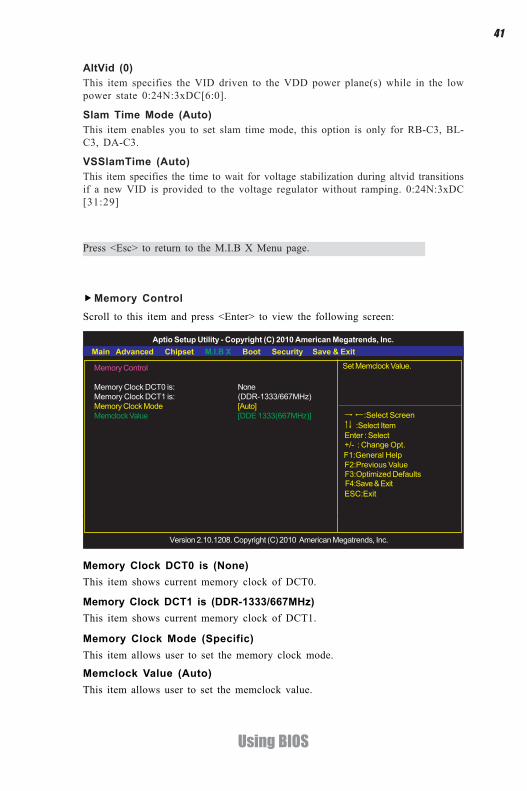
Memory Control
Memory Clock DCT0 is: NoneMemory Clock DCT1 is: (DDR-1333/667MHz)Memory Clock Mode [Auto]Memclock Value [DDE 1333(667MHz)]
Aptio Setup Utility - Copyright (C) 2010 American Megatrends, Inc.
Version 2.10.1208. Copyright (C) 2010 American Megatrends, Inc.
+/- : Change Opt.Enter : Select
F1:General Help
:Select Screen:Select Item
F2:Previous Value F3:Optimized Defaults
F4:Save & Exit ESC:Exit
Set Memclock Value.
Main Advanced Chipset M.I.B X Boot Security Save & Exit
Memory ControlScroll to this item and press <Enter> to view the following screen:
Memory Clock DCT1 is (DDR-1333/667MHz)This item shows current memory clock of DCT1.
Memory Clock Mode (Specific)This item allows user to set the memory clock mode.
Memory Clock DCT0 is (None)This item shows current memory clock of DCT0.
Memclock Value (Auto)This item allows user to set the memclock value.
Press <Esc> to return to the M.I.B X Menu page.

42
Using BIOS
Auto Detect DIMM/PCI Clk (Enabled)When this item is enabled, BIOS will disable the clock signal of free DIMM/PCI slots.
CPU/HT Reference Clock (MHz) (200)Use this item to set the CPU/HT Reference Clock through clock gen.
CPU Unlock (Disabled)This item allows you to enable or disable CPU unlock function. It works depends onyour CPU.
HT control
Current Width Up: 16 bitUpstream Link Width [Auto]Current Width Down: 16 bitDownstream Link Width [Auto]Current IO HT Freq: 2600MHzIO HT Frequency [Auto]
Aptio Setup Utility - Copyright (C) 2010 American Megatrends, Inc.
Version 2.10.1208. Copyright (C) 2010 American Megatrends, Inc.
Main Advanced Chipset M.I.B X Boot Security Save & Exit
+/- : Change Opt.Enter : Select
F1:General Help
:Select Screen:Select Item
F2:Previous Value F3:Optimized Defaults
F4:Save & Exit ESC:Exit
Set Upstream Link Width.
Current Width Up (16 bit)This item shows the current Upstream Link Width.
Current Width Down (16 bit)This item shows the current Downstream Link Width.
Upstream Link Width (Auto)This item allows you to set Upstream Link Width.
Downstream Link Width (Auto)This item allows you to set Downstream Link Width.
Current IO HT Freq (2600MHz)This item shows the current IO HT Frequency.
IO HT Frequency (Auto)This item allows you to set IO HT Frequency.
HT ControlScroll to this item and press <Enter> to view the following screen:
Press <Esc> to return to the M.I.B X Menu page.

43
Using BIOS
NB Voltage (Default)This item allows user to adjust NB voltage when enabled.
CPU Current Voltage (1.452V)This item shows the current CPU voltage.
NB Current Voltage (N/A)This item shows the current NB voltage.
VDIMM Current Voltage (1.572V)This item displays the current DIMM voltage.
SB Voltage (Default)This item allows user to adjust SB voltage when enabled.
VDIMM Voltage (Default)This item allows user to adjust DIMM voltage when enabled.
CPU Voltage (Default)This item allows user to adjust CPU voltage when enabled.

44
Using BIOS
Boot Configuration
Bootup Numlock State [On]Quiet Boot [Enabled]
Set Boot Priority1st Boot [CD/DVD]2nd Boot [Hard Disk]3rd Boot [USB Floppy]4thBoot [USB CD/DVD]5th Boot [USB Hard Disk]6th Boot [USB KEY]7th Boot [Network]8th Boot [UEFI]
Aptio Setup Utility - Copyright (C) 2010 American Megatrends, Inc.
Version 2.10.1208. Copyright (C) 2010 American Megatrends, Inc.
Main Advanced Chipset M.I.B X Boot Security Save & Exit
+/- : Change Opt.Enter : Select
F1:General Help
:Select Screen:Select Item
F2:Previous Value F3:Optimized Defaults
F4:Save & Exit ESC:Exit
Select the keyboard Numlockstate
This page enables you to set the keyboard NumLock state and Boot device priority.
Boot Menu
Bootup NumLock State (On)This item determines if the NumLock key is active or inactive at system start-uptime.
Quiet Boot (Enabled)If enebled, BIOS will show a full screen logo at boot, if disabled, BIOS will set theinitial display mode to BIOS and show the diagnostic POST screen at boot.
1st/2nd/3rd/4th/5th/6th/7th/8th Boot (CD/DVD /Hard Disk /USB Floppy /USBCD/DVD /USB Hard Disk /USB KEY /Network /UEFI)Use these items to determine the device order the computer used to look for anoperating system to load at start-up time. The devices showed here will be differentdepending on the exact devices installed on your motherboard.

45
Using BIOS
Administrator Password
Aptio Setup Utility - Copyright (C) 2010 American Megatrends, Inc.
Version 2.10.1208. Copyright (C) 2010 American Megatrends, Inc.
Main Advanced Chipset M.I.B X Boot Security Save & Exit
+/- : Change Opt.Enter : Select
F1:General Help
:Select Screen:Select Item
F2:Previous Value F3:Optimized Defaults
F4:Save & Exit ESC:Exit
Set Setup AdministratorPassword
This page enables you to set setup administrator and password.Security Menu
Administrator PasswordThis item allows you to set or change administrator password.
46
Using BIOS
Save Changes and ExitDisacard Changes and ExitSave Chnges and ResetDisacard Changes and Reset
Save OptionsSave ChngesDiscard Changes
Restore DefaultsSave as User DefaultsRestore User Defaults
Boot Override
Aptio Setup Utility - Copyright (C) 2010 American Megatrends, Inc.
Version 2.10.1208. Copyright (C) 2010 American Megatrends, Inc.
Main Advanced Chipset M.I.B X Boot Security Save & Exit
+/- : Change Opt.Enter : Select
F1:General Help
:Select Screen:Select Item
F2:Previous Value F3:Optimized Defaults
F4:Save & Exit ESC:Exit
Exit system setup after savingthe changes.
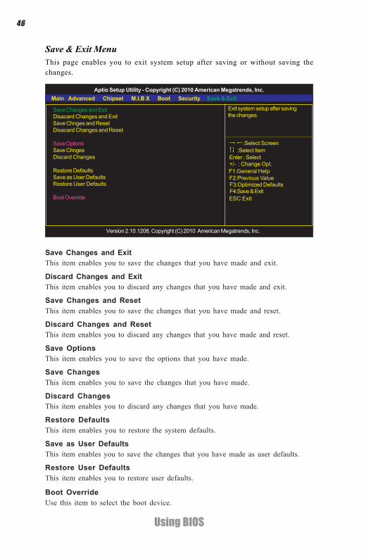
This page enables you to exit system setup after saving or without saving thechanges.
Save & Exit Menu
Boot OverrideUse this item to select the boot device.
Save Changes and ExitThis item enables you to save the changes that you have made and exit.
Discard Changes and ExitThis item enables you to discard any changes that you have made and exit.
Save Changes and ResetThis item enables you to save the changes that you have made and reset.
Save OptionsThis item enables you to save the options that you have made.
Save ChangesThis item enables you to save the changes that you have made.
Discard ChangesThis item enables you to discard any changes that you have made.
Restore DefaultsThis item enables you to restore the system defaults.
Save as User DefaultsThis item enables you to save the changes that you have made as user defaults.
Restore User DefaultsThis item enables you to restore user defaults.
Discard Changes and ResetThis item enables you to discard any changes that you have made and reset.
47
Using BIOS
Updating the BIOSYou can download and install updated BIOS for this motherboard from themanufacturer’s Web site. New BIOS provides support for new peripherals, improve-ments in performance, or fixes for known bugs. Install new BIOS as follows:
1 If your motherboard has a BIOS protection jumper, change the setting toallow BIOS flashing.
2 If your motherboard has an item called Firmware Write Protect in Ad-vanced BIOS features, disable it. (Firmware Write Protect preventsBIOS from being overwritten.)
3 Prepare a bootable device or create a bootable system disk. (Refer toWindows online help for information on creating a bootable systemdisk.)
4 Download the Flash Utility and new BIOS file from the manufacturer’sWeb site. Copy these files to the bootable device.
5 Turn off your computer and insert the bootable device in your com-puter. (You might need to run the Setup Utility and change the the bootpriority items on the Advanced BIOS Features Setup page, to forceyour computer to boot from the bootable device first.)
6 At the C:\ or A:\ prompt, type the Flash Utility program name and the filename of the new BIOS and then press <Enter>. Example:AMINF340.EXE040706.ROM
7 When the installation is complete, remove the bootable device from thecomputer and restart your computer. If your motherboard has a FlashBIOS jumper, reset the jumper to protect the newly installed BIOS frombeing overwritten. The computer will restart automatically.

48
Using BIOS
Memo
49
Using the Motherboard Software
Chapter 4
Using the Motherboard Software
Auto-installing under Windows XP/Vista/7The Auto-install DVD-ROM/CD-ROM makes it easy for you to install the driversand software for your motherboard.
If the Auto-install DVD-ROM/CD-ROM does not work on your system,you can still install drivers through the file manager for your OS (forexample, Windows Explorer). Refer to the Utility Folder Installation Noteslater in this chapter.
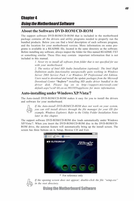
The support software DVD-ROM/CD-ROM disc loads automatically under WindowsXP/Vista/7. When you insert the DVD-ROM/CD-ROM disc in the DVD-ROM/CD-ROM drive, the autorun feature will automatically bring up the install screen. Thescreen has three buttons on it, Setup, Browse CD and Exit.
If the opening screen does not appear; double-click the file “setup.exe”in the root directory.
About the Software DVD-ROM/CD-ROMThe support software DVD-ROM/CD-ROM that is included in the motherboardpackage contains all the drivers and utility programs needed to properly run thebundled products. Below you can find a brief description of each software program,and the location for your motherboard version. More information on some pro-grams is available in a README file, located in the same directory as the software.Before installing any software, always inspect the folder for files named README.TXTor something similar. These files may contain important information that is notincluded in this manual.
2. The notice of Intel HD Audio Installation (optional): The Intel HighDefinition audio functionality unexpectedly quits working in WindowsServer 2003 Service Pack 1 or Windows XP Professional x64 Edition.Users need to download and install the update packages from the MicrosoftDownload Center “before” installing HD audio driver bundled in thedriver disk. Please log on to http://support.microsoft.com/default.aspx?scid=kb;en-us;901105#appliesto for more information.
1. Never try to install all software from folder that is not specified for usewith your motherboard.
* For reference only

50
Using the Motherboard Software
Drivers
Setup Click the Setup button to run the software installation program.Select from the menu which software you want to install.
Browse CD The Browse CD button is the standard Windows command thatallows you to open Windows Explorer and show the contents of thesupport disk.
Before installing the software from Windows Explorer, look for a filenamed README.TXT or something similar. This file may containimportant information to help you install the software correctly.
Some software is installed in separate folders for different operatingsystems.
In installing the software, execute a file named SETUP.EXE by double-clicking the file and then following the instructions on the screen.
Exit The EXIT button closes the Auto Setup window.
UtilitiesLists the software utilities that are available on the disk.
InformationDisplays the path for all software and drivers available on the disk.
Running SetupFollow these instructions to install device drivers and software for the motherboard:
1. Click Setup. The installation program begins:
The following screens are examples only. The screens and driver lists will bedifferent according to the motherboard you are installing.
The motherboard identification is located in the upper left-hand corner.
Utilities Click the Utilities button to display the application software andother software utilities that are available on the disk. Select the sofwareyou want to install then follow installation procedure.

51
Using the Motherboard Software
2. Click Next. The following screen appears:
3. Check the box next to the items you want to install. The default optionsare recom-mended.
4. Click Next run the Installation Wizard. An item installation screen appears:
5. Follow the instructions on the screen to install the items.
Drivers and software are automatically installed in sequence. Follow theonscreen instructions, confirm commands and allow the computer torestart a few times to complete the installation.

52
Using the Motherboard Software
Manual InstallationInsert the disk in the DVD-ROM/CD-ROM drive and locate the PATH.DOC file inthe root directory. This file contains the information needed to locate the drivers foryour motherboard.
Look for the chipset and motherboard model; then browse to the directory and pathto begin installing the drivers. Most drivers have a setup program (SETUP.EXE) thatautomatically detects your operating system before installation. Other drivers havethe setup program located in the operating system subfolder.
If the driver you want to install does not have a setup program, browse to theoperating system subfolder and locate the readme text file (README.TXT orREADME.DOC) for information on installing the driver or software for your oper-ating system.
Utility Software ReferenceAll the utility software available from this page is Windows compliant. They areprovided only for the convenience of the customer. The following software is fur-nished under license and may only be used or copied in accordance with the terms ofthe license.
These software(s) are subject to change at anytime without prior notice.Please refer to the support disk for available software.
Windows Vista/7 will appear below UAC (User Account Control) messageafter the system restart. You must select “Allow” to install the next driver.Continue this process to complete the drivers installation.

53
AMD RAID Configuration
Setting Up a bootable RAID ArrayThis section explains how to configure a bootable AMD RAID array.
Setting Up the BIOS
Use the arrow keys to select Advanced menu (see Figure 1.1), then selectSATA Configuration and press Enter.
The Integrated Peripherals screen (or a screen similar to it) appears.
Figure 1.2 SATA Configuration Screen
Use the arrow keys to select the SATA Configuration (see Figure 1.2) andglobally set SATA Configuration to RAID.
Start your computer, then press Delete to enter the BIOS setup.The BIOS CMOS Setup Utility screen appears.
Figure 1.1 BIOS CMOS Setup Utility Main Screen
1
2
3
Chapter 5Setting Up AMD SB950 RAID Configuration
BIOS Information
System Date [ Mon 04/18/2011]System Time [05:44:29]
Choose the system defaultlanguage
Aptio Setup Utility - Copyright (C) 2010 American Megatrends, Inc.
Version 2.10.1208. Copyright (C) 2010 American Megatrends, Inc.
Main Advanced Chipset M.I.B X Boot Security Save & Exit
F1:General Help
:Select ItemEnter : Select
:Select Screen
F2:Previous Value F3:Optimized Defaults
F4:Save & Exit ESC:Exit
+/- : Change Opt.
SATA Configuration
Serial-ATA Controller [Enabled]SATA Mode [IDE Mode]PATA Controller [Enabled]eSATA 6Gb/s Controller Mode [AHCI Mode]SATA Port1 Not PresentSATA Port2 Not PresentSATA Port3 Not PresentSATA Port4 Not PresentSATA Port5 Not PresentSATA Port6 Not Present
Aptio Setup Utility - Copyright (C) 2010 American Megatrends, Inc.
Version 2.10.1208. Copyright (C) 2010 American Megatrends, Inc.
Main Advanced Chipset M.I.B X Boot Security Save & Exit
Enabled/Disabled SATAContreller
F1:General Help
:Select ItemEnter : Select
:Select Screen
F2:Previous Value F3:Optimized Defaults
F4:Save & Exit ESC:Exit
+/- : Change Opt.
54
AMD RAID Configuration
5 Enter the RAID BIOS Setup by pressing Ctrl-F when prompted, and proceedto set up the AMD RAID BIOS as described in the next section.
The PC reboots.Press F4 to save the configuration and exit.
Configuring the AMD RAID BIOS (Windows XP Installation)The AMD RAID BIOS set up lets you choose the RAID type and which hard drivesyou want to make part of the array.
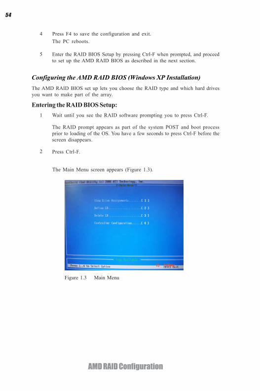
Entering the RAID BIOS Setup:1 Wait until you see the RAID software prompting you to press Ctrl-F.
The RAID prompt appears as part of the system POST and boot processprior to loading of the OS. You have a few seconds to press Ctrl-F before thescreen disappears.
Press Ctrl-F.
4
2
The Main Menu screen appears (Figure 1.3).
Figure 1.3 Main Menu

55
AMD RAID Configuration
Select [2], then select LD 1 in the following page.3
The Define LD Menu screen appears (Figure 1.4).
Figure 1.4 Define LD Menu
Using the Define a New Array ScreenIf necessary, press the tab key to move from field to field until the appropriate fieldis highlighted.
• Selecting the RAID Mode
By default, this is set to Mirroring. To change to a different RAID mode,press the spacebar until the mode that you want appears in the RAID Modebox—RAID0/1/10/JBOD.
Note: Not all RAID levels are supported on all platforms.
Stripe block size is given in kilobytes, and affects how data is arranged on thedisk. It is recommended to leave this value at the default Optimal, which is64KB, but the values can be 64 KB and 128 KB. When choose RAID 1, theStripe block size is unchangable.
• Selecting the Stripe Block Size
Note: If you want to use the function of the following RAID Mode, you haveto install enough HDD.
RAID READY (1 piece of HDD); RAID 0,1 ,JBOD (2 or more pieces ofHDD); RAID 0+1 (4 pieces of HDD)
56
AMD RAID Configuration
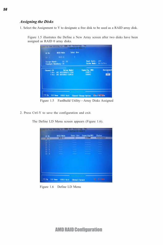
Figure 1.5 illustrates the Define a New Array screen after two disks have beenassigned as RAID 0 array disks.
Figure 1.5 FastBuild Utility—Array Disks Assigned
Assigning the Disks1. Select the Assignment to Y to designate a free disk to be used as a RAID array disk.
2. Press Ctrl-Y to save the configuration and exit.
The Define LD Menu screen appears (Figure 1.6).
Figure 1.6 Define LD Menu
57
AMD RAID Configuration
Figure 1.7 Main Menu
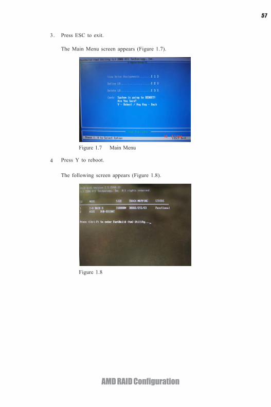
Press ESC to exit.
4 Press Y to reboot.
3.
The Main Menu screen appears (Figure 1.7).
Figure 1.8
The following screen appears (Figure 1.8).

58
AMD RAID Configuration
1 Copy all files in "...\RAID\ATI\SB950\Floppy\Win3264" to a floppy disk.
After you complete the RAID BIOS setup, boot from the Windows CD.
Figure 1.10 Windows Setup—Specify Devices
Installing the RAID DriversYour system may come with a Windows install CD that already includes AMD RAIDdrivers. If so, then this section is not relevant.
If that is not the case (or you are trying to install a new version of Windows), thenyou will need an AMD RAID driver F6 install floppy. Check to see if one came withyour system. If not, you can create one by downloading the appropriate driverpackage and following the steps in this section.
Press F6 and wait a few moments for the Windows Setup screen toappear.
The Windows Setup program starts.2
3
a Insert the floppy that has the RAID driver, press S, then press Enter.Specify the AMD drivers.4
Figure 1.9

59
AMD RAID Configuration
b Select “ATI AHCI Compatible RAID Controller-x86 platform” and pressEnter for 32-bit OS or Select “ATI AHCI Compatible RAID Controller-x64platform” and press Enter for 64-bit OS.
The following Windows Setup screen appears listing both drivers:.
Figure 1.12 Windows Setup—AMD drives listed
Press Enter to continue with Windows XP Installation.Be sure to leave the floppy disk inserted in the floppy drive until the bluescreen portion of Windows XP installation is completed, then take out thefloppy.
Follow the instructions on how to install Windows XP.After Windows XP is completely installed, it is recommended that youinstall the ForceWare software in order to access the FastBuild RAID Man-agement tool.
Note: Each time you add a new hard drive to a RAID array, the RAID driverwill have to be installed under Windows once for that hard drive. Afterthat, the driver will not have to be installed.
5
6
Figure 1.11 Windows Setup—Selected SCSI Adapter
The following Windows Setup screen appears:

60
AMD RAID Configuration
Memo

61
ATI CrossFireTM Technology Support
Chapter 6
ATI CrossFireXTM Technology Support
This motherboard supports the ATI CrossFireXTM Technology that allows you toinstall multi-graphics processing units (GPU) graphics cards. Follow the installationprocedures in this section.
Requirements1 Two or three identical CrossFireXTM ready graphic cards are needed for the
setup of 2-way / 3-way CrossFireXTM configuration.2 You would need one or two CrossfireXTM bridge cable.3 Make sure that your graphics card driver supports the ATI CrossFireXTM
technology. Download the latest driver from the ATI website(www.ati.com).
4 Make sure that your power supply unit (PSU) can provide at least theminimum power required by your system.
Installing CrossFireXTM graphics cards
1. Insert the CrossFireXTM graphics cards into the PCIEX16 slots. Make sure that thecard is properly seated on the slot.
A. For 2-way configuration, install two graphic cards on PCIEX16_1 & PCIEX16_2and connect them with the CrossFireTM Bridge.
* For reference only

62
ATI CrossFireTM Technology Support4. Connect an auxiliary power source from the power supply to the graphics cards.
3. Connect the cable from your monitors to the CrossFireXTM ready graphics cardinstalled on the PCIEX16_1 slot.
Monitor Cable
B. For 3-way configuration, two CrossFireTM Bridges are needed to connect thethree graphic cards.
* For reference only
* For reference only
Monitor Cable
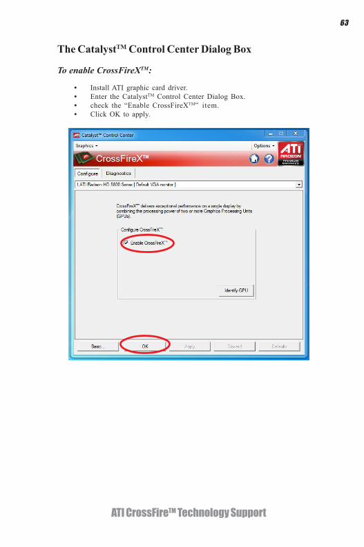
63
ATI CrossFireTM Technology Support
The CatalystTM Control Center Dialog Box
To enable CrossFireXTM:
• Install ATI graphic card driver.• Enter the CatalystTM Control Center Dialog Box.• check the “Enable CrossFireXTM” item.• Click OK to apply.

64
ATI CrossFireTM Technology Support
Memo
65
Trouble Shooting
Chapter 7
Trouble Shooting
Start up problems during assembly
After assembling the PC for the first time you may experience some start upproblems. Before calling for technical support or returning for warranty, this chaptermay help to address some of the common questions using some basic troubleshootingtips.
a) System does not power up and the fans are not running.
1.Disassemble the PC to remove the VGA adaptor card, DDR memory, LAN, USBand other peripherals including keyboard and mouse. Leave only the motherboard,CPU with CPU cooler and power supply connected. Turn on again to see if theCPU and power supply fans are running.
2. Make sure to remove any unused screws or other metal objects such as screwdriversfrom the inside PC case. This is to prevent damage from short circuit.
3. Check the CPU FAN connector is connected to the motherboard.
4. For Intel platforms check the pins on the CPU socket for damage or bent. A bentpin may cause failure to boot and sometimes permanent damage from short circuit.
5. Check the 12V power connector is connected to the motherboard.
6. Check that the 12V power & ATX connectors are fully inserted into themotherboard connectors. Make sure the latches of the cable and connector arelocked into place.
b) Power is on, fans are running but there is no display
1. Make sure the monitor is turned on and the monitor cable is properly connectedto the PC.
2. Check the VGA adapter card (if applicable) is inserted properly.
3. Listen for beep sounds. If you are using internal PC speaker make sure it isconnected. a. continuous 3 short beeps : memory not detected b. 1 long beep and 8 short beeps : VGA not detected
c) The PC suddenly shuts down while booting up.1. The CPU may experience overheating so it will shutdown to protect itself.Ensure the CPU fan is working properly.

66
Trouble Shooting
Your computer, like any electrical appliance, requires proper care and maintenance.Here are some basic PC care tips to help prolong the life of the motherboard andkeep it running as best as it can.
1. Keep your computer in a well ventilated area. Leave some space between the PC and the wall for sufficient airflow.
2. Keep your computer in a cool dry place. Avoid dusty areas, direct sunlight
Start up problems after prolong useAfter a prolong period of use your PC may experience start up problems again.This may be caused by breakdown of devices connected to the motherboard such asHDD, CPU fan, etc. The following tips may help to revive the PC or identify thecause of failure.1. Clear the CMOS values using the CLR_CMOS jumper. Refer to CLR_CMOSjumper in Chapter 2 for Checking Jumper Settings in this user manual. Whencompleted, follow up with a Load Optimised Default in the BIOS setup.
2. Check the CPU cooler fan for dust. Long term accumulation of dust will reduceits effectiveness to cool the processor. Clean the cooler or replace a new one ifnecessary.
3. Check that the 12V power & ATX connectors are fully inserted into themotherboard connectors. Make sure the latches of the cable and connector arelocked into place.
4. Remove the hard drive, optical drive or DDR memory to determine which ofthese component may be at fault.
and areas of high moisture content.
3. Routinely clean the CPU cooler fan to remove dust and hair.
4. In places of hot and humid weather you should turn on your computer once every other week to circulate the air and prevent damage from humidity.
5. Add more memory to your computer if possible. This not only speeds up the system but also reduces the loading of your hard drive to prolong its life span.
6. If possible, ensure the power cord has an earth ground pin directly from the wall outlet. This will reduce voltage fluctuation that may damage sensitive devices.
Maintenance and care tips
2. From the BIOS setting, try to disable the Smartfan function to let the fan run atdefault speed. Doing a Load Optimised Default will also disable the Smartfan.

Pow
er
Buon
is
pr
esse
d bu
t PC
fails
to st
art.
Yes
Chec
k if
Pow
er S
uppl
y U
nit(
PSU
) is
wor
king
No
No
Any
Beep
sou
ndN
oCL
R CM
OS
and
chec
k
if CP
U 1
2V p
ower
is c
onne
cted
art t
he P
C st
Re
Prob
lem
with
PSU
or b
oard
?
If bo
ard
prob
lem
-> c
onta
ct R
MA
AC p
ower
cor
d is
plu
ed
gg
and
PSU
switc
h is
turn
ed o
n?
Yes
oble
m
rBo
ard
p
-> c
onta
ct R
MA
No
- If 3
sho
rt b
eeps
:
DIM
M m
emor
y no
t pro
perly
inse
rted
or m
emor
y fa
ilure
- If 1
long
bee
p an
d 8
shor
t bee
ps:
VGA
not d
etec
ted
Yes
Yes
Hal
t at P
OST
scr
een
Yes
R CM
OLC
S an
d re
star
t.
If fa
il, c
onta
ct R
MA
Yes
No
Perip
hera
l dev
ice
issu
e
-H
DD
pro
blem
.
-CM
OS
setu
p er
ror,
dne
e to
CLR
CMO
S.
Syst
em fa
il to
sta
rt o
r uns
tabl
e
aer
mod
ify B
IOS
seng
. M
CLR
CO
S an
d re
star
t
Turn
on
PSU
sw
itch
or c
onne
ct to
wal
l soc
ket
star
t. e
and
rNo
Chec
k if
mon
itor h
sadi
s pla
y
Chec
k if
mon
itor
has
dis
play
6
67
Basic
Tro
uble
shoo
ting
Flow
char
t

68
Trouble Shooting
Memo