copyright joseph greene 20011 mechanical properties of composites professor joe greene csu, chico
TRANSCRIPT
Copyright Joseph Greene 2001 1
Mechanical Properties of Composites
Professor Joe Greene
CSU, CHICO

Copyright Joseph Greene 2001 2
Mechanical Properties
• Comparison with Other Materials
• Environmental Effects
• Test Considerations
Copyright Joseph Greene 2001 3
Objectives • Recognize some of the basic differences in mechanical,
physical, and thermal properties of composite materials that distinguish them from metals;
• Understand the various design techniques and advantages of using composites to obtain high performance and highly efficient structures;
• Describe the effects of t he specific use environment on the behavior of composite materials for a range of operational conditions;
• Discuss various test methods and approaches in evaluating and characterizing the mechanical properties of composites for design and analysis needs.

Copyright Joseph Greene 2001 4
Comparison with Other Materials• Metals and metallic structures have been used for over 100 years in
engineering and are well understood materials with a large database of design data and experience.
• Plastics have been used for the last 50 years and have extensive database of properties and manufacturing information.
• Composites technology is much more recent (25 years) with a database and analysis that are just emerging.
• Aerospace industry– Relies heavily on aluminum and titanium alloys
• Automotive industry– Relies heavily on steel and aluminum
• Al and titanium limitations– Exposure to salt water and harsh environments causes corrosion
– Heavier than when compared to polymers, foam, and composites
– Low strain-to failure modes can cause permature failure
Copyright Joseph Greene 2001 5
Historical• 1940s and 1950s, aerospace industry looked at high
performance composites as replacement for steel .– Early materials were glass fiber and polyester resin.– Limited to non-structural applications.– Resin and fibers developed and material systems matured.– During the 1960s new fiber systems were developed for
structural components• High strength glass fibers (S-901), • Aramid (Kevlar 49), carbon and graphite systems
– Composite advantages• High strength to weight and stiffness to weight due to low density• Manufacturing ease and environmental resistance• Low cost and design versatility: fiber placement for strength and
stiffness selectivity.
Copyright Joseph Greene 2001 6
Mechanical Properties• Traditional materials have homogeneous properties.
– The strength and modulus are the same no matter where the sample is taken from. Ferrous (steel, iron) and non ferrous materials, (Al,Cu,Pb)
– If pieces were cut from different locations in a metal plate, the pieces would have the same:
• Density, internal structure, tensile strength, modulus, elongation, impact, etc..
– If pieces were cut in one direction and then another one 90° from it, the tensile strength, tensile modulus, impact and other properties would be the same.
• Composite materials are made up of two or more distinct materials, one for reinforcing and the other for holding the fibers together in a matrix.
• Composite materials have non-homogeneous properties and are called inhomogeneous materials with anisotropic properties.– Fibers are stronger in one direction than the other one due to aspect ratio.– The properties of the area around the resin is much lower than the properties around the
fiber.
Copyright Joseph Greene 2001 7
Mechanical Properties• Common anisotropic materials
– Plywood, reinforced concrete due to steel rebar.
• Composites are often fabricated with stronger properties in one direction versus the other one, or have properties stronger in a particular region.– Fibers are placed with woven roving or fabric with fibers in
the 0° /90° direction, or fibers in the 40° /60° direction.– Filament winding and lay-up composite sheet can result in a
composite with uni-directional properties.– Samples of the composite are often taken in the 0° direction
and reported as maximum values. • The tensile strengths and modulus are divided by the density of the
composite to give the specific strength and specific modulus• Figure 4-1 provides properties for unidirectional composites• Figure 4-2 provides properties for quasi-isotropic composites
Copyright Joseph Greene 2001 8
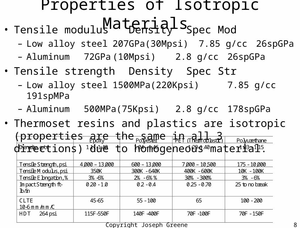
Properties of Isotropic Materials • Tensile modulus Density Spec
Mod– Low alloy steel 207GPa(30Mpsi) 7.85 g/cc 26spGPa
– Aluminum 72GPa (10Mpsi) 2.8 g/cc 26spGPa
• Tensile strength Density Spec Str– Low alloy steel 1500MPa(220Kpsi) 7.85 g/cc 191spMPa
– Aluminum 500MPa(75Kpsi) 2.8 g/cc 178spGPa
• Thermoset resins and plastics are isotropic (properties are the same in all 3 directions) due to homogeneous material.
Epoxy Polyester PET (Thermoplastic) PolyurethaneDensity, g/cc 1.11-1.40 1.04 - 1.46 1.29-1.40 1.03 - 1.15
Tensile Strength, psi 4,000 – 13,000 600 – 13,000 7,000 – 10,500 175 - 10,000Tensile Modulus, psi 350K 300K - 640K 400K - 600K 10K - 100KTensile Elongation, % 3%-6% 2% - 6%% 30% - 300% 3% - 6%Impact Strength ft-lb/in
0.20 - 1.0 0.2 - 0.4 0.25 - 0.70 25 to no break
CLTE10-6 mm/mm/C
45-65 55 - 100 65 100 - 200
HDT 264 psi 115F-550F 140F -400F 70F -100F 70F - 150F
Copyright Joseph Greene 2001 9
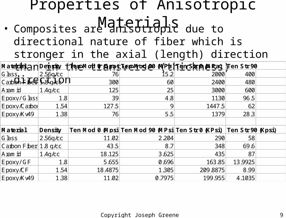
Properties of Anisotropic Materials • Composites are anisotropic due to directional nature of fiber
which is stronger in the axial (length) direction than in the transverse (thickness) direction
Material Density Ten Mod 0 (Gpa) Ten Mod 90 (MPa) Ten Str 0 (MPa) Ten Str 90Glass 2.56g/cc 76 15.2 2000 400Carbon Fiber 1.8 g/cc 300 60 2400 480Aramid 1.4g/cc 125 25 3000 600Epoxy/ Glass 1.8 39 4.8 1130 96.5Epoxy/Carbon 1.54 127.5 9 1447.5 62Epoxy/Kv49 1.38 76 5.5 1379 28.3
Material Density Ten Mod 0 (Mpsi) Ten Mod 90 (MPsi) Ten Str 0 (KPsi) Ten Str 90 (Kpsi)Glass 2.56g/cc 11.02 2.204 290 58Carbon Fiber 1.8 g/cc 43.5 8.7 348 69.6Aramid 1.4g/cc 18.125 3.625 435 87Epoxy/ GF 1.8 5.655 0.696 163.85 13.9925Epoxy/CF 1.54 18.4875 1.305 209.8875 8.99Epoxy/Kv49 1.38 11.02 0.7975 199.955 4.1035
Copyright Joseph Greene 2001 10
Mechanical Properties of Composites• Polymer composites are made up of a resin and a fiber
renforcement.– Both contribute to the strength and stiffness of the composite
• The higher the fiber % the higher the properties• The more unidirectional the fiber, the higher the properties are in that
direction and the weaker they are in the transverse direction.– Filament winding and prepreg tape have very high directional
properties• Directional effects are minimized by having alternating fiber angles
– Example, 0°/90° ply with +/-45° fiber ply.• Fiber bonding to matrix is key to high strength properties.
Copyright Joseph Greene 2001 11
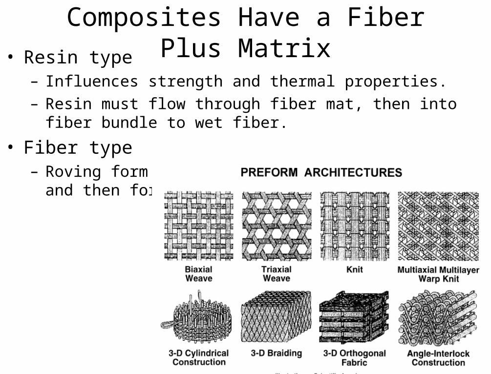
Composites Have a Fiber Plus Matrix• Resin type
– Influences strength and thermal properties.
– Resin must flow through fiber mat, then into fiber bundle to wet fiber.
• Fiber type– Roving form that is woven into a glass sheet and then formed to shape
(preform)
Copyright Joseph Greene 2001 12
Composites Have Directional Properties• Fiber type
– Different fibers have different strength, modulus, and strain at failure• Figure 4-3• Generally, the stiffer the fiber, the smaller the strain at failure.
– Kevlar-Epoxy unidirectional properties- Table 4.3
• Fiber %– The higher the fiber %, the higher the properties
• Fiber % for automotive is 35% by volume• Fiber % for aerospace is 60% by volume
• Fiber orientation– The more unidirectional the fiber the stronger the properties are.– Properties of unidirectional glass-Epoxy Composites- Table 4.6– Properties of Unidirectional Materials- Table 4.7– Properties of Pan and Pitch Carbon Fibers- Table 4.9
Copyright Joseph Greene 2001 13
Composites Have Directional Properties• Fiber Orientation
– Carbon fiber is Amoco high modulus pitch based fiber– Unidirectional laminate with 60% fiber and epoxy resin tested along the fibers (0°) and
across the fibers (90°)– Isotropic laminate has 0°, 30°, 60°, 90°, 120°, 150° stacking sequence– Table 4.10: Effect of orientation on carbon fiber properties
• Unidirectional had double the strength and triple the modulus as a quasi-isotropic material• Unidirectional material had 10% of the strength and 3% of the modulus in the transverse direction
as the quasi-isotropic laminate
– Table 4.11: Mechanical Properties of Carbon-Fiber Composites with Epoxy and PEEK • Epoxy resin had 25% higher tensile strength and 60% higher tensile modulus than the peek
composite in the 0° direction• Peek resin had 40% higher strength and 330% higher Fracture strain in the 45° direction than epoxy.

Copyright Joseph Greene 2001 14
Composites Have Directional Properties• Fiber Type
– Table 4.12. Tensile Properties of different types of carbon fiber• T200, T50, T650, T1000, P55, P100 types of carbon fiber
– Table 4.13. Unidirectional Composite Properties• ATB and ATS are acetylene terminated epoxy resins• XAS and Celion are PAN based carbon fibers• Narmco and 117951 are BMI matrix resins, Bismaleimide
– Table 4.14. Unidirectional Fiber and Thermoplastic Composites• PEEK, APC, and PEKK are different grades of aromatic ketones
– Table 4.15. Mechanical Properties of Hybrid Yarn– Table 4.16. Unidirectional, comingled, and cowoven fabric– Table 4.17. Mechanical Properties of Composites
Copyright Joseph Greene 2001 15
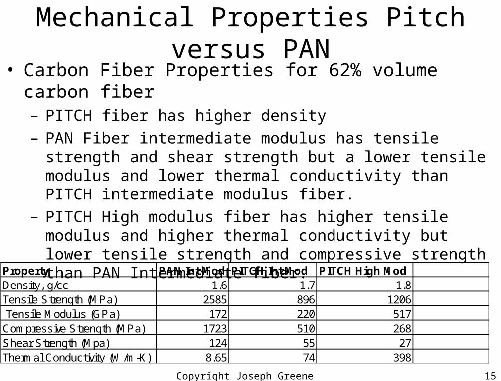
Mechanical Properties Pitch versus PAN• Carbon Fiber Properties for 62% volume carbon fiber
– PITCH fiber has higher density
– PAN Fiber intermediate modulus has tensile strength and shear strength but a lower tensile modulus and lower thermal conductivity than PITCH intermediate modulus fiber.
– PITCH High modulus fiber has higher tensile modulus and higher thermal conductivity but lower tensile strength and compressive strength than PAN Intermediate fiber.
Property PAN Int Mod PITCH Int Mod PITCH High ModDensity, g/cc 1.6 1.7 1.8Tensile Strength (MPa) 2585 896 1206 Tensile Modulus (GPa) 172 220 517Compressive Strength (MPa) 1723 510 268Shear Strength (Mpa) 124 55 27Thermal Conductivity (W/m-K) 8.65 74 398
Copyright Joseph Greene 2001 16
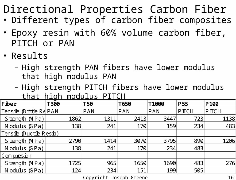
Directional Properties Carbon Fiber • Different types of carbon fiber composites• Epoxy resin with 60% volume carbon fiber, PITCH or PAN• Results
– High strength PAN fibers have lower modulus that high modulus PAN
– High strength PITCH fibers have lower modulus that high modulus PITCH
Fiber T300 T50 T650 T1000 P55 P100Tensile (Brittle Resin)PAN PAN PAN PAN PITCH PITCH Strength (MPa) 1862 1311 2413 3447 723 1138 Modulus (GPa) 138 241 170 159 234 483Tensile (Ductile Resin) Strength (MPa) 2790 1414 3070 3795 890 1206 Modulus (GPa) 138 241 170 234 483Compresion Strength (MPa) 1725 965 1650 1690 483 276 Modulus (GPa) 124 234 151 199 505
Copyright Joseph Greene 2001 17
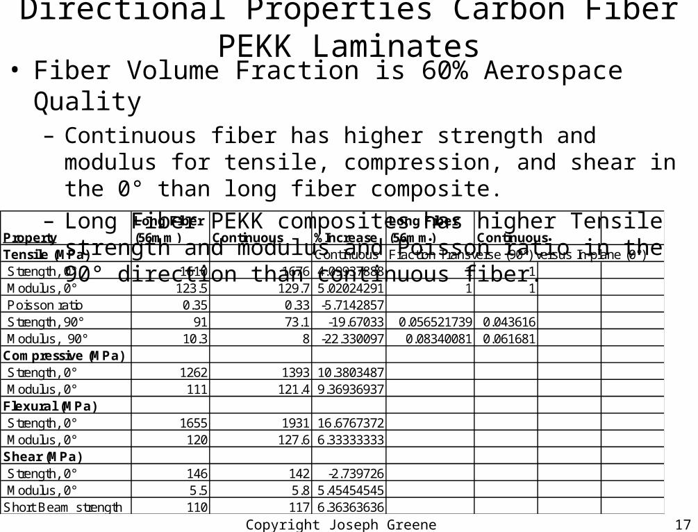
Directional Properties Carbon Fiber PEKK Laminates• Fiber Volume Fraction is 60% Aerospace Quality
– Continuous fiber has higher strength and modulus for tensile, compression, and shear in the 0° than long fiber composite.
– Long Fiber PEKK composites has higher Tensile strength and modulus and Poisson ratio in the 90° direction than continuous fiber.
PropertyLong Fiber (56mm) Continuous %Increase
Long Fiber (56mm) Continuous
Tensile (MPa) Continuous Fraction Transverse (90°) versus In-plane (0°) Strength, 0° 1610 1676 4.09937888 1 1 Modulus, 0° 123.5 129.7 5.02024291 1 1 Poisson ratio 0.35 0.33 -5.7142857 Strength, 90° 91 73.1 -19.67033 0.056521739 0.043616 Modulus, 90° 10.3 8 -22.330097 0.08340081 0.061681Compressive (MPa) Strength, 0° 1262 1393 10.3803487 Modulus, 0° 111 121.4 9.36936937Flexural (MPa) Strength, 0° 1655 1931 16.6767372 Modulus, 0° 120 127.6 6.33333333Shear (MPa) Strength, 0° 146 142 -2.739726 Modulus, 0° 5.5 5.8 5.45454545Short Beam strength 110 117 6.36363636
Copyright Joseph Greene 2001 18
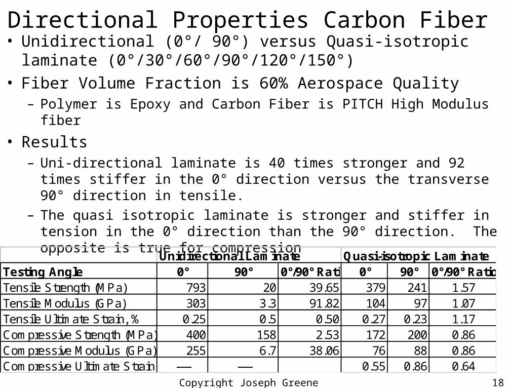
Directional Properties Carbon Fiber • Unidirectional (0°/ 90°) versus Quasi-isotropic laminate
(0°/30°/60°/90°/120°/150°) • Fiber Volume Fraction is 60% Aerospace Quality
– Polymer is Epoxy and Carbon Fiber is PITCH High Modulus fiber
• Results– Uni-directional laminate is 40 times stronger and 92 times stiffer in
the 0° direction versus the transverse 90° direction in tensile.
– The quasi isotropic laminate is stronger and stiffer in tension in the 0° direction than the 90° direction. The opposite is true for compression
Unidirectional Laminate Quasi-isotropic LaminateTesting Angle 0° 90° 0°/90° Ratio 0° 90° 0°/90° RatioTensile Strength (MPa) 793 20 39.65 379 241 1.57Tensile Modulus (GPa) 303 3.3 91.82 104 97 1.07Tensile Ultimate Strain, % 0.25 0.5 0.50 0.27 0.23 1.17Compressive Strength (MPa) 400 158 2.53 172 200 0.86Compressive Modulus (GPa) 255 6.7 38.06 76 88 0.86Compressive Ultimate Strain, % ---- ---- 0.55 0.86 0.64

Copyright Joseph Greene 2001 19
Directional Properties Carbon Fiber • Unidirectional (0°) versus Quasi-isotropic laminate (45°) • Results
– Uni-directional laminate is stronger and stiffer in the 0° direction versus the transverse 45° direction in tensile for Epoxy and PEEK
– The quasi isotropic laminate is has higher fracture strain% in the 45° direction than the 0° direction for epoxy and for PEEK.
Polymer MatrixFiber Orientation
Tensile Strength (MPa)
Tensile Modulus(GPa)
Fracture Strain %
Epoxy 0° 932 83 1.1Epoxy 45° 126 1.3PEEK 0° 740 51 1.1PEEK 45° 194 14 4.3
Copyright Joseph Greene 2001 20
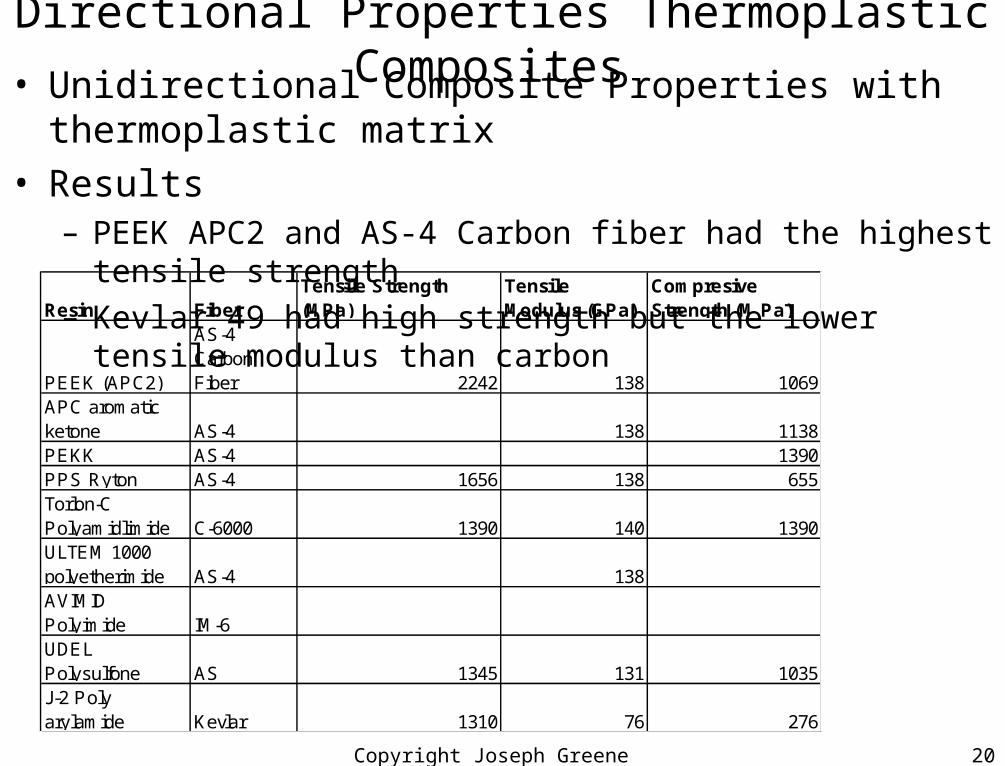
Directional Properties Thermoplastic Composites • Unidirectional Composite Properties with thermoplastic matrix• Results
– PEEK APC2 and AS-4 Carbon fiber had the highest tensile strength
– Kevlar 49 had high strength but the lower tensile modulus than carbon
Resin FiberTensile Strength (MPa)
Tensile Modulus (GPa)
Compresive Strength (M Pa)
PEEK (APC2)
AS-4 Carbon Fiber 2242 138 1069
APC aromatic ketone AS-4 138 1138PEKK AS-4 1390PPS Ryton AS-4 1656 138 655Torlon-C Polyamidlimide C-6000 1390 140 1390ULTEM 1000 polyetherimide AS-4 138AVIMID Polyimide IM-6 UDEL Polysulfone AS 1345 131 1035J-2 Poly arylamide Kevlar 1310 76 276
Copyright Joseph Greene 2001 21
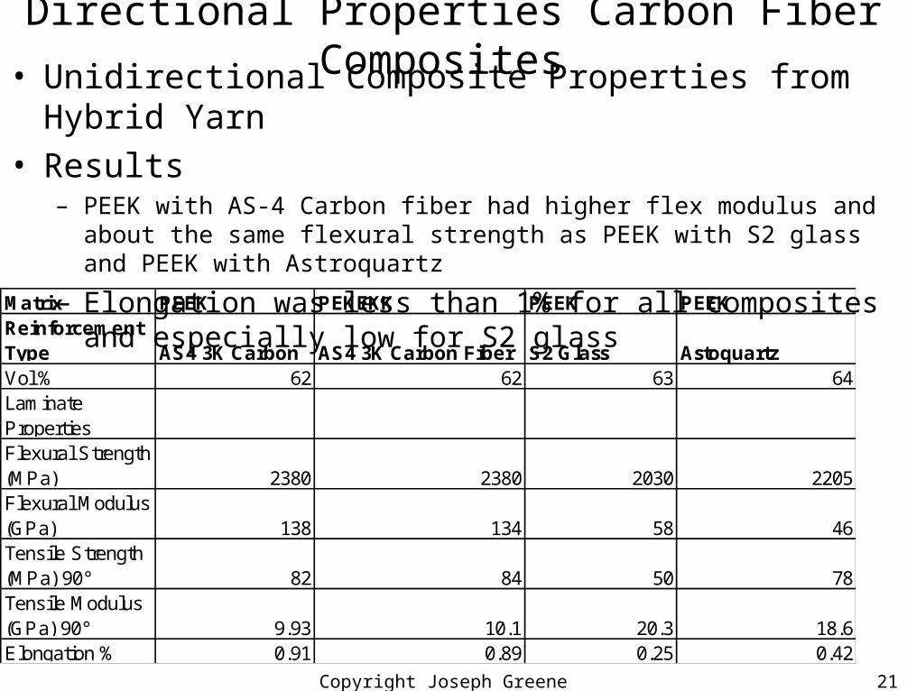
Directional Properties Carbon Fiber Composites • Unidirectional Composite Properties from Hybrid Yarn• Results
– PEEK with AS-4 Carbon fiber had higher flex modulus and about the same flexural strength as PEEK with S2 glass and PEEK with Astroquartz
– Elongation was less than 1% for all composites and especially low for S2 glass
Matrix PEEK PEKEKK PEEK PEEKReinforcement Type AS4 3K Carbon AS4 3K Carbon Fiber S2 Glass AstoquartzVol % 62 62 63 64Laminate PropertiesFlexural Strength (MPa) 2380 2380 2030 2205Flexural Modulus (GPa) 138 134 58 46Tensile Strength (MPa) 90° 82 84 50 78Tensile Modulus (GPa) 90° 9.93 10.1 20.3 18.6Elongation % 0.91 0.89 0.25 0.42
Copyright Joseph Greene 2001 22
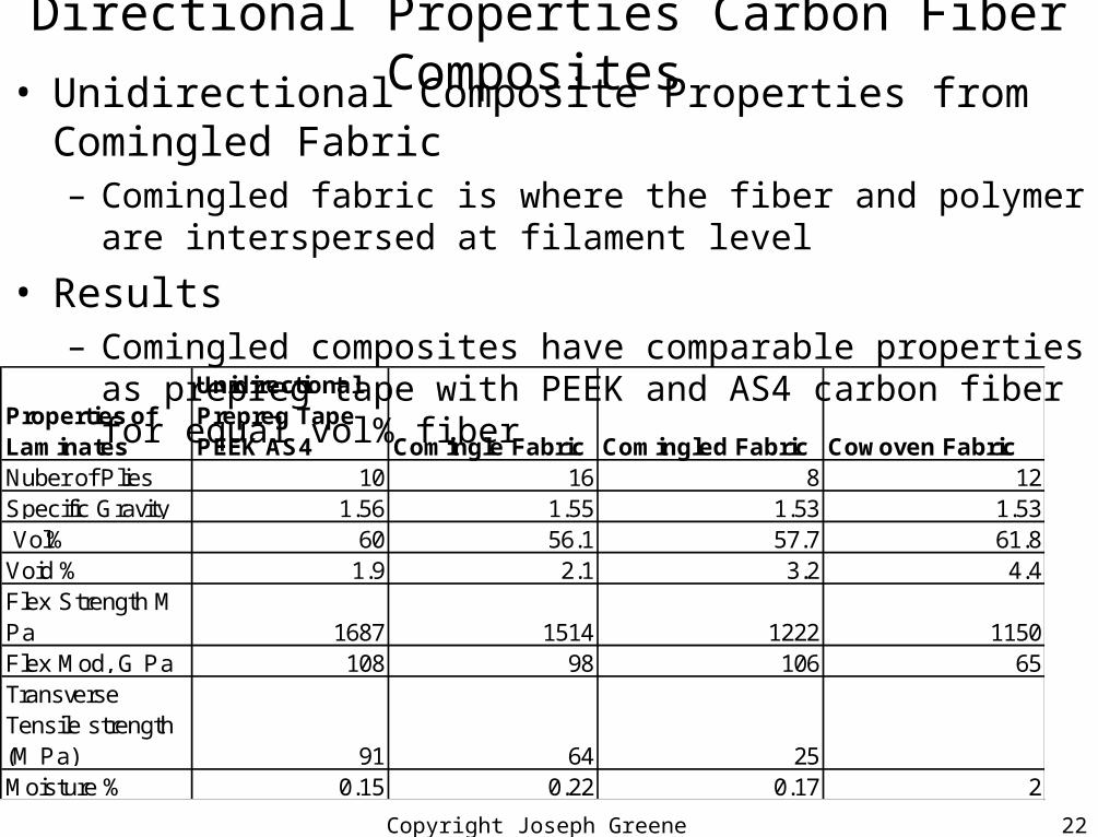
Directional Properties Carbon Fiber Composites • Unidirectional Composite Properties from Comingled Fabric
– Comingled fabric is where the fiber and polymer are interspersed at filament level
• Results– Comingled composites have comparable properties as prepreg tape
with PEEK and AS4 carbon fiber for equal vol% fiber
Properties of Laminates
Unidirectional Prepreg Tape PEEK AS4 Comingle Fabric Comingled Fabric Cowoven Fabric
Nuber of Plies 10 16 8 12Specific Gravity 1.56 1.55 1.53 1.53 Vol% 60 56.1 57.7 61.8Void % 1.9 2.1 3.2 4.4Flex Strength M Pa 1687 1514 1222 1150Flex Mod, G Pa 108 98 106 65Transverse Tensile strength (M Pa) 91 64 25Moisture % 0.15 0.22 0.17 2
Copyright Joseph Greene 2001 23
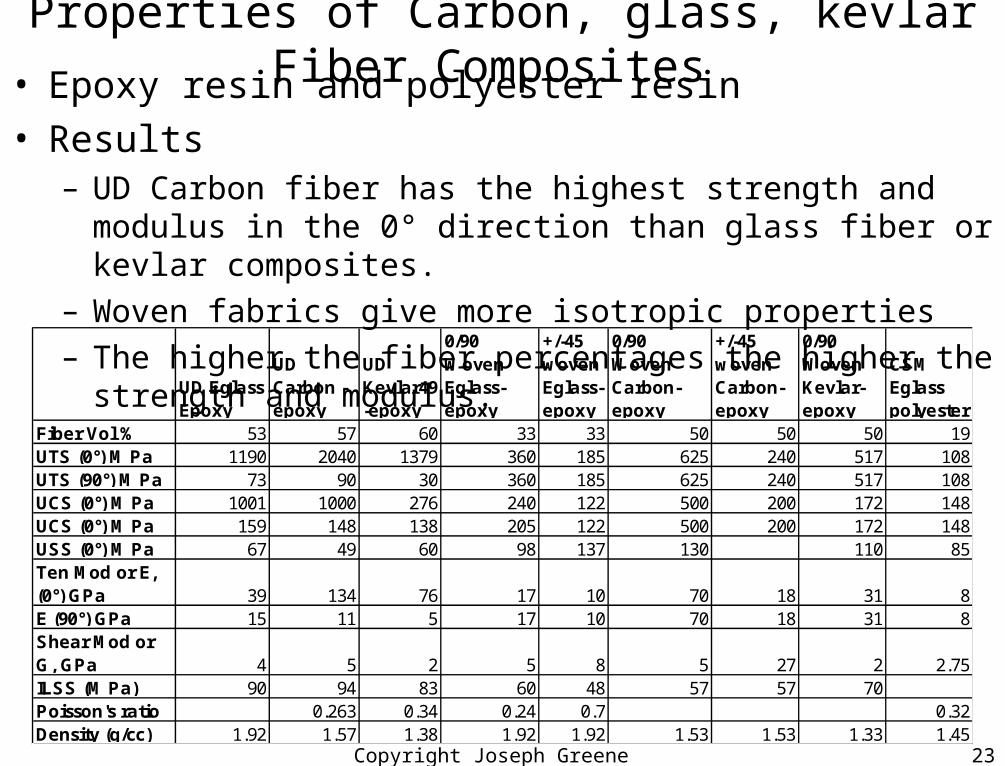
Properties of Carbon, glass, kevlar Fiber Composites • Epoxy resin and polyester resin• Results
– UD Carbon fiber has the highest strength and modulus in the 0° direction than glass fiber or kevlar composites.
– Woven fabrics give more isotropic properties
– The higher the fiber percentages the higher the strength and modulus.
UD Eglass Epoxy
UD Carbon -epoxy
UD Kevlar49 -epoxy
0/90 Woven Eglass-epoxy
+/-45 woven Eglass-epoxy
0/90 Woven Carbon-epoxy
+/-45 woven Carbon-epoxy
0/90 Woven Kevlar-epoxy
CSM Eglass polyester
Fiber Vol % 53 57 60 33 33 50 50 50 19UTS (0°) M Pa 1190 2040 1379 360 185 625 240 517 108UTS (90°) M Pa 73 90 30 360 185 625 240 517 108UCS (0°) M Pa 1001 1000 276 240 122 500 200 172 148UCS (0°) M Pa 159 148 138 205 122 500 200 172 148USS (0°) M Pa 67 49 60 98 137 130 110 85Ten Mod or E, (0°) GPa 39 134 76 17 10 70 18 31 8E (90°) GPa 15 11 5 17 10 70 18 31 8Shear Mod or G, GPa 4 5 2 5 8 5 27 2 2.75ILSS (M Pa) 90 94 83 60 48 57 57 70Poisson's ratio 0.263 0.34 0.24 0.7 0.32Density (g/cc) 1.92 1.57 1.38 1.92 1.92 1.53 1.53 1.33 1.45

Copyright Joseph Greene 2001 24
Rule of Mixtures • Mechanical properties of a composite material made from two
materials can be estimated based upon the volume fraction of each material times the material property of each.– Modulus, strength, CLTE, shrinkage, density, and others
– formula: Ec = Ef*Vf + EmVm = Ef*Vf + Em(1-Vf), where E is Tensile modulus, f is fiber, m is matrix, and c is composite
– Example,Composite: Epoxy and Glass
vol frac fib modulus, Gpastrength, Mpa given0 5 50 Ef 75 Gpa
0.1 12 165 Em 5 Gpa0.2 19 280 ten str glas 1200 MPa0.3 26 395 ten str epox 50 MPa0.4 33 5100.5 40 625 formula: Ec = Ef*Vf + EmVm = Ef*Vf + Em(1-Vf)0.6 47 7400.7 54 8550.8 61 9700.9 68 1085
1 75 1200
Rule of Mixtures for Density
0
0.2
0.4
0.6
0.8
1
0 0.5 1
Weight fraction fibers
vil
um
e f
rac
tio
n
fib
ers
Series1
Copyright Joseph Greene 2001 25
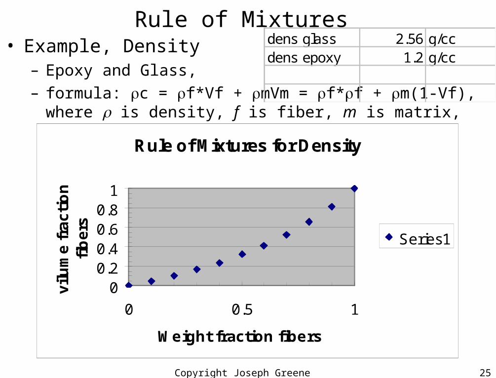
Rule of Mixtures • Example, Density
– Epoxy and Glass,
– formula: c = f*Vf + mVm = f*f + m(1-Vf), where is density, f is fiber, m is matrix, and c is composite
Rule of Mixtures for Density
00.20.40.60.8
1
0 0.5 1
Weight fraction fibers
vil
um
e f
rac
tio
n
fib
ers
Series1
dens glass 2.56 g/ccdens epoxy 1.2 g/cc
Copyright Joseph Greene 2001 26
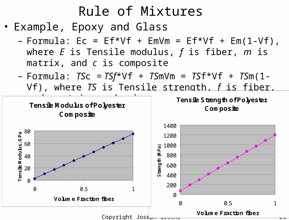
Rule of Mixtures • Example, Epoxy and Glass
– Formula: Ec = Ef*Vf + EmVm = Ef*Vf + Em(1-Vf), where E is Tensile modulus, f is fiber, m is matrix, and c is composite
– Formula: TSc = TSf*Vf + TSmVm = TSf*Vf + TSm(1-Vf), where TS is Tensile strength, f is fiber, m is matrix, and c is composite
Tensile Strength of Polyester Composite
0
200
400
600
800
1000
1200
1400
0 0.5 1
Volume Fraction fiber
Str
eng
th (
MP
a)
Tensile Modulus of Polyester Composite
0
20
40
60
80
0 0.5 1
Volume Fraction fiber
Ten
sile
Mo
du
lus,
GP
a
Copyright Joseph Greene 2001 27
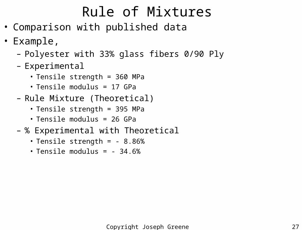
Rule of Mixtures • Comparison with published data• Example,
– Polyester with 33% glass fibers 0/90 Ply– Experimental
• Tensile strength = 360 MPa• Tensile modulus = 17 GPa
– Rule Mixture (Theoretical)• Tensile strength = 395 MPa• Tensile modulus = 26 GPa
– % Experimental with Theoretical• Tensile strength = - 8.86%• Tensile modulus = - 34.6%
Copyright Joseph Greene 2001 28
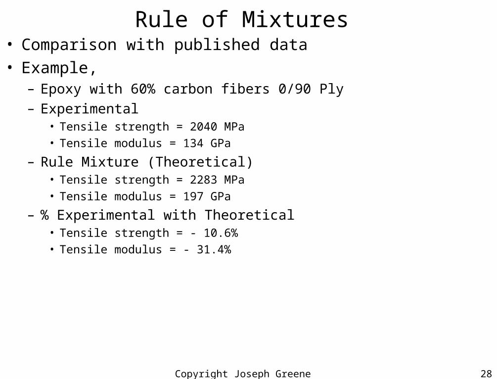
Rule of Mixtures • Comparison with published data• Example,
– Epoxy with 60% carbon fibers 0/90 Ply– Experimental
• Tensile strength = 2040 MPa• Tensile modulus = 134 GPa
– Rule Mixture (Theoretical)• Tensile strength = 2283 MPa• Tensile modulus = 197 GPa
– % Experimental with Theoretical• Tensile strength = - 10.6%• Tensile modulus = - 31.4%

Copyright Joseph Greene 2001 29
Composites Properties with Exposure• Exposure type
Copyright Joseph Greene 2001 30
Polyimides• Bismaleimide (BMI) resins
– Advantages• Low processing temperature versus polyimides (Cured at
350F)• Standard epoxy processing equipment can be used since
same T.• Postcure of 475 F is required to complete
polymerization.• BMI are fully formed polyimides when reacted to form
composite• Thus, no volatiles are removed and no consolidation
problems• Tack and drape are quite good because of the liquid
component of the reactants
Copyright Joseph Greene 2001 31
Test Considerations• Metal systems
– isotropic, linear, and elastic such that only a few tests are required to obtain basic tensile stiffness properties that describe the mechanical performance in most situations
– Only two values are needed: Tensile modulus (stiffness) and poisson’s ratio (longitudinal strain divided by axial strain)
– Both are determined from the same tensile test
• Shear modulus (G) is related to shear strain () by Shear Stress :
= G() or Shear Stress = Shear Modulus times strain
Copyright Joseph Greene 2001 32
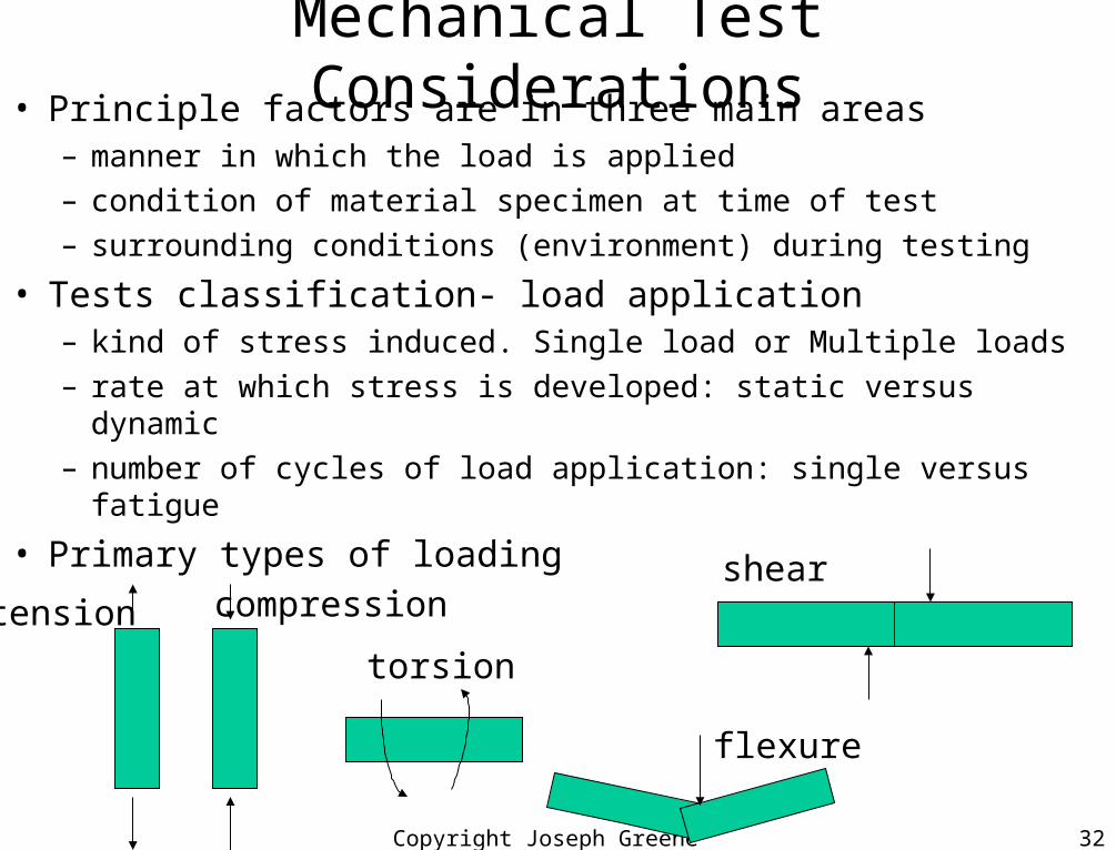
Mechanical Test Considerations• Principle factors are in three main areas
– manner in which the load is applied
– condition of material specimen at time of test
– surrounding conditions (environment) during testing
• Tests classification- load application– kind of stress induced. Single load or Multiple loads
– rate at which stress is developed: static versus dynamic
– number of cycles of load application: single versus fatigue
• Primary types of loading
tension compressionshear
torsion
flexure
Copyright Joseph Greene 2001 33
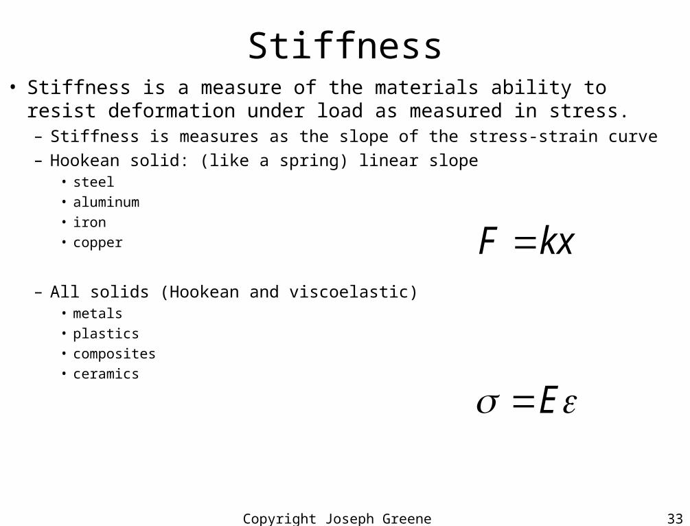
Stiffness• Stiffness is a measure of the materials ability to resist deformation under load as
measured in stress.– Stiffness is measures as the slope of the stress-strain curve– Hookean solid: (like a spring) linear slope
• steel
• aluminum
• iron
• copper
– All solids (Hookean and viscoelastic)• metals
• plastics
• composites
• ceramics
kxF
E
Copyright Joseph Greene 2001 34
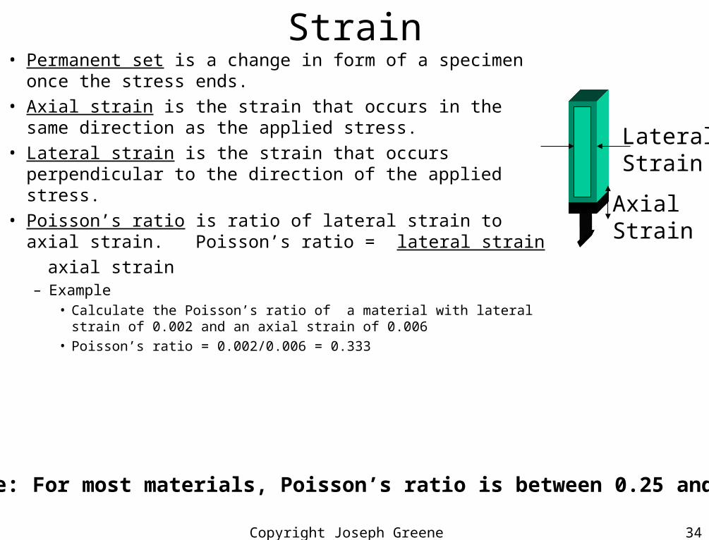
Strain• Permanent set is a change in form of a specimen once the stress
ends.• Axial strain is the strain that occurs in the same direction as the
applied stress.• Lateral strain is the strain that occurs perpendicular to the
direction of the applied stress.• Poisson’s ratio is ratio of lateral strain to axial strain. Poisson’s
ratio = lateral strain
axial strain– Example
• Calculate the Poisson’s ratio of a material with lateral strain of 0.002 and an axial strain of 0.006
• Poisson’s ratio = 0.002/0.006 = 0.333
AxialStrain
LateralStrain
Note: For most materials, Poisson’s ratio is between 0.25 and 0.5

Copyright Joseph Greene 2001 35
Test Considerations• Degree of anisotropy
– Degree of anisotropy depends on how symmetrical the material is.• Metals are isotropic materials that have an infinite number of symmetry planes
(properties are the same in different directions or planes) and end up as noted above with two material properties (E and )
• Opposite extreme are materials with no symmetry planes and would require 21 material properties and require extensive testing inorder to design a structure with the best finite element computer programs (NASTRAN)
• Most composites used today are developed in two-dimensional form and consequently have one plane of symmetry.
– Called transversely isotropic for unidirectional materials– Stress-strain relationships requires 5 material properties
» Modulus in 2 directions, E11 and E22
» Shear Modulus in 2 directions, E12, E21
» Poisson’s ratio,
Copyright Joseph Greene 2001 36
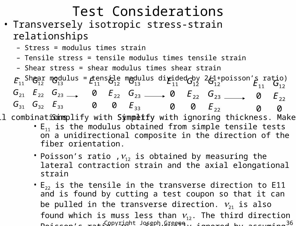
Test Considerations• Transversely isotropic stress-strain relationships
– Stress = modulus times strain
– Tensile stress = tensile modulus times tensile strain
– Shear stress = shear modulus times shear strain
– Shear modulus = tensile modulus divided by 2(1+poisson’s ratio)
333231
232221
131211
EGG
GEG
GGE
33
2322
131211
00
0
E
GE
GGE
22
2322
121211
00
0
E
GE
GGE
00
0 22
1211
E
GE
All combinations Simplify with Symmetry Simplify with ignoring thickness. Make 2D• E11 is the modulus obtained from simple tensile tests on a unidirectional
composite in the direction of the fiber orientation.
• Poisson’s ratio ,12 is obtained by measuring the lateral contraction strain and the axial elongational strain
• E22 is the tensile in the transverse direction to E11 and is found by cutting a test coupon so that it can be pulled in the transverse direction. 21 is also found
which is muss less than 12. The third direction Poisson’s ratio, 23 , is usually ignored by assuming 2-D
• G12, the shear modulus, is measured using a simple hoop-wound tubes or +/- 10° to +-15° tensile coupons. Shear strains are measured then the modulus is calculated.

Copyright Joseph Greene 2001 37
Test Considerations• Estimating properties with micromechanics
– Some basic properties can be estimated using what is called structure-property relationships or micromechanics.
– Assumptions• Composite ply is macroscopically homogeneous and linearly elastic• Fibers are linearly elastic and homogeneous• Matrix is linearly elastic and homogeneous• Both fiber and matrix are free of voids• Interface is completely bonded, and there is no transitional region between the matrix and reinforcement• Mechanical properties of individual constituents re the same whether they are made by themselves or
made up within the composite
– The values of E11 (longitudal modulus), 12 (principal Poisson’s ratio), and 11 (principal expansion coefficient), can be expressed in terms of the matrix/fiber properties themselves and the volume fraction of the respective ingredients.
– These expressions are derived from the Rule of Mixtures theory as:
Tensile modulus: E11 = Vf Ef + Vm Em
Poisson’s ratio : 12 = Vf f + Vm m
Expansion coefficient 11 = Vf f + Vm m
Density: 11 = Vf f + Vm mwhere, f is the fiber, m is the matrix, V is the volume fraction of fiber (Vf) or matrix (Vm) and same subscripts work for the others properties as well.

Copyright Joseph Greene 2001 38
Fatigue Properties• Fatigue
– High performance composites were developed for aerospace applications because Al has poor fatigue performance.
• Aircraft applications can have 106 to 108 load cycle range.– Al and some steels falter in this range– Al has 10% fatigue endurance limit versus static values
» Aluminum will only be able to support 10% of the static load before the fatigue test.– Composites have 60% the static (one cycle) ultimate strength
• Fiber reinforced composites are more stable and forgiving in fatigue applications and do well in fatigue tests since a loss of a few failed fibers is not noticeable to the overall strength of the fiber composite
– Figure 4-4. Axial compressive fatigue of graphite/epoxy laminate– Composites tend to stabilize early in fatigue loading through the following mechanisms,
each of which absorbs energy or redirects the energy to other parts of the composite» Matrix micro-cracking which absorbs energy by breaking matrix bonds» Blunting of cracks at the fiber surface which reduces further crack growth» Delamination between layers which may relieve internal cure stresses» Stress redistribution and load sharing in composite structure» Energy dissipation resulting through matrix viscoelastic effects (internal damping)
Copyright Joseph Greene 2001 39
Vibration and Damping Properties• Vibrations are often a natural consequence of stiffness
– For composites, the fiber stiffness is balanced with the matrix resin plasticity
– Composites provide excellent properties for aircraft and missile control surfaces where fast, rigid response is needed.
– Composites are less noisy and provide lower vibration transmission than metals.
• Damping in composites is due to microcracking, internal tip blunting, matrix viscoelastic effects and plasticity.
• Damping capability of composites can be almost twice that of some steels, and ten times better than aluminum and titanium alloys.
• Figure 4-5. Specific damping capacity versus stress
Copyright Joseph Greene 2001 40
Design Approach Comparison
• Metal structures provide a well-established database from 100 years of structural use that include exposure to a wide range of environmental and operational conditions.
• Material choice for metallic structures– Define operational loads and environments
– Select several candidate metal materials to meet service environment
– Conduct trade studies using the basic design properties.• For metals the following mechanical properties are needed:
– Tensile modulus (E), Poisson’s ratio, and thermal expansion (CLTE)
– Compare the material allowables and select the appropriate metal candidates to satisfy structural, cost, and manufacturing considerations
Copyright Joseph Greene 2001 41
Design Approach Comparison• Composites widen the options for designers who can now
tailor the composite to meet structural requirements through a variety of combinations of fibers and matrices and percentages of each.– Selection of specific fiber (or several) to meet stiffness and strength requirements
– Orientation of the fiber into the load direction to take the majority of the loads
– Selection of resin-to-fiber volume ratio for optimizing fiber delivery
• Structural analysis with finite elements is needed to asses structural integrity– Along with the required material properties,
• Two stiffness values in two directions (E and ) and two thermal expansion coefficients.
• More values might be needed if the composite is very anisotropic.
• Fewer are required if more isotropic.
Copyright Joseph Greene 2001 42
Environmental Effects• Composites are affected by thermal, moisture, fatigue, creep, and aging (service
life)– For metals
• Environment attacks homogeneous material and not at interfaces, layers, and porous regions
– For composites• Environment attacks inhomogeneous material at interfaces, layers, and porous regions
• Temperature– Often the most severe environmental effect
• Affects the entire service life of the composite– Initially part is cured in molding operation and then post cured– Max use temperature is usually the highest temperature the composite is exposed to during
molding or post cure» If molded at 250F and not post cured, then the highest use temperature is 250F» If molded at 250F and then post cured at 350F, then the use temp is 350F» If molded at 600F (PEEK or Polyimids) then the use temp is 600F.
– Cure process generates some undesirable effects, e.g., creation of residual cure stresses that can lead to porosity, microcracking, and delamination.
» To reduce these effects, reduce the cure temperature, reduce ramp temperature during heating and cool-down processing cycles.
– Especially, important with compression fatigue loading in addition to inherent thermal stresses
Copyright Joseph Greene 2001 43
Environmental Effects• Temperature (continued)
– Thermal cycling• Solar radiation, daily temperature variations due to transportation, weather conditions due to
seasons and geography
– Normal operational limits for static or isothermal exposure• Rocket motor cases- -65°F to 165°F range for operational and storage conditions• Automotive body panels (doors, hoods, etc.)- -40F to 140F• Automotive engine parts (valve covers, hood inners)- -40F to 300F
– Extended limits for • Cryogenic tanks or operations in high temperature (engine blades), moderate temperature (aircraft
parts) and low temperature (space structures)• Very often these exposures are for short duration (few seconds to a few hundred hours). If longer
the exterior is usually protected with insulating material.
– Aeroheating for nose cone (reentry) and rocket motor applications• Requires careful analysis of thermal stresses and review of allowable elevated temperature
mechanical properties
– The mechanical properties are tested at service temperatures for• Modulus, strength, impact, etc.
– Figure 4-6- Effect of thermal post cure on fracture toughness of graphite/epoxy
Copyright Joseph Greene 2001 44
Environmental Effects• Moisture
– Composites absorb moisture through the matrix, the fiber, the fiber-matrix interface, and porous regions or area where microcracking or delamination have occurred
– Table 4-1 illustrates the degree to which polymer absorbs moisture• Sample is submerged in water at a particular temperature and the amount of water
absorbed is measured for several days and weeks until saturation.
– Moisture degrades the mechanical properties of polymer materials.• Rule of thumb is to have a maximum of 3% moisture for a polymer material• Materials that absorb more then that should NOT be selected for applications that are
exposed to a wet environment (contact with water for long periods of time), but can be used in applications with short exposure to moisture.
– Fibers do not absorb water (except for aramid Kevlar 49 fiber)– Resins absorb moisture for the composite and results in
• Lower strengths, modulus, and microcracking• Properties of composite materials are tested in the wet condition if product will be used
in a wet environment, e.g., submersible crafts
– Moisture barriers can be used, e.g., coatings, paints, vapor deposited metallic layers, aluminum foil layers, grease seals, plastic film.
Copyright Joseph Greene 2001 45
Environmental Effects• Fatigue
– Composites perform well under fatigue loadings when compared to metals, maintaining 60% of their ultimate tensile strength.
– Tension fatigue and stress rupture under tension loading have not had a substantial effect on composite strength degradation.
– Primary fatigue difficulty has been in compression fatigue.• Fibers are normally designed to carry tension loads
• Compression loading puts more dependence on the resin to transfer shear and compression loads to adjacent fibers and from layer to layer than does tensile loading.
• Primary concern for aircraft industry has always been with compression fatigue under hot-wet conditions (90-100% relative humidity and 180°F temperatures)
• Figure 4-4
Copyright Joseph Greene 2001 46
Environmental Effects• Creep/Delamination Behavior
– Fiber behaves in a rigid manner– Resin is prone to creep or relax under load, especially at higher
temperatures or long durations– For metals, creep isn’t important unless at temperatures above 400F– For polymer matrix composites, creep can be an issue at temperatures
above 100F (for thermoplastics) and 200F (urethanes) and 300F (epoxies)
– Creep is a result of the viscoelastic nature of polymers, but can be offset by
• Fiber orientation in the direction of high loads to reduce creep loading• Increased fiber content• Select stiffer fibers• Reduction of level of stress in the design• Utilization of initial loading cycles to relieve residual stresses

Copyright Joseph Greene 2001 47
Environmental Effects• Aging/Service life considerations
– Typical composite structures are designed to survive 10 to 25 years
– Following steps help in design• Define service environment in terms of exposure time
• Review database of materials for a match
• Conduct accelerated aging test
• Verify aging tests with real time aging on samples stored near operational conditions
• Figure 4-7- Pressure vessel with series of burst tests after exposure to environmental conditions