cordless multi purpose metal cutter model no. ey4542
TRANSCRIPT

© Panasonic Electric Works Co., Ltd. 2008.All rights reserved. Unauthorized copying and distri-bution is a violation of law.
Order Number PTD0810X43CE
Cordless Multi Purpose Metal CutterModel No. EY4542EuropeOceania
TABLE OF CONTENTSPAGE PAGE
1 Warning -------------------------------------------------------------- 22 Specifications ----------------------------------------------------- 23 Troubleshooting Guide ----------------------------------------- 34 Disassembly and Assembly Instructions ---------------- 55 Wiring Connection Diagram ---------------------------------126 Schematic Diagram ---------------------------------------------127 Exploded View and Replacement Parts List -----------13

2
1 WarningCaution:
• Pb free solder has a higher melting point that standard solder; Typicall the melting point is 50 - 70°F (30 - 40°C) higher. Pleaseuse a soldering iron with temperature control and adjust it to 750 ± 20°F (400 ± 10°C). In case of using high temperature solder-ing iron, please be careful not to heat too long.
• Pb free solder will tend to splash when heated too high (about 1100°F / 600°C).
2 Specifications

3
3 Troubleshooting Guide(Refer to Wiring Connection Diagram)

4
3.1. Trial Operation (after checking Troubleshooting Guide.)

5
4 Disassembly and Assembly Instructions4.1. How to Disassemble the Blade.
Ref. No. 1A Procedure 1A Blade removal.CAUTION:
The blade will be hot right after cutting. Be sure to let the blade cool down before removing it.
1. Remove the battery pack from the tool.2. Hold the spindle lock button down. This prevents the blade from rotation.3. Use the provided hex wrench to loosen the hex bolt.NOTE:
Keep the hex wrench in the storage slot on the tool’s body when not using it.
4. Remove the hex bolt and outer washer.5. Use the retracting handle to retract (open) the lower guard.6. Carefully remove the blade.7. Clean the tool if necessary.CAUTION:
Be careful to avoid cutting your hands on the blade.

6
4.2. How to Reassemble the Main Unit.(The main unit can be opened without removing the shoe.)
Ref. No. 2A Procedure 2A Removal of the lower guard.1. Remove the dust case.2. Remove the 4 screws securing the safety cover B. Take out the safety cover B.3. Remove the lower guard stopper.4. Take out the front cover and transparent cover.5. Remove the inner washer and the stop ring.6. Remove the lower guard with connecting the spring.NOTE:
When removing the lower guard from the main unit, do not stretch the spring.

7
Ref. No. 2B Procedure 2A → 2B Removal of the shoe.NOTE:
It is possible to disassemble the main unit without removing the shoe.
1. Hold the unit with the vice.2. Push out the spring pin with a rod having a diameter of 6mm.NOTE:
Do not tap the spring pin strongly. If to do so, the hole of spring may cause the deformation.
Ref. No. 2C Procedure 2A → 2C Removal of the Housing.1. Loosen depth adjustint nut and take out square screw.2. Loosen 8 housing screws.3. Slightly pull the safety cover A forward and then pull it upward.It is then possible to disassembly the main unit or to check the switch block and motor.NOTE:
Do not remove a screw that holds spring except in the case of damage.

8
Ref. No. 2D Procedure 2A → 2C → 2D Removal of the gear box block.1. Remove the off lock lever and the off lock spring.2. Loosen 3 screws where securing the driving block with the hous-ing in order to take out the gear box block from the main unit.3. Press the shaft lock button and carefully remove the driving block assembly.4. Remove 5 screws and carefully open the gear box housing.NOTE:
The internal parts of gear box block can be removed one after another.
NOTE:The lock button spring may pop out if it is not pushed in while removing the driving block.

9
4.3. How to Assemble the Main Unit.CAUTION:
The proper operation of the “off lock lever” is critical for the safe use and operation of the cutter. Be extra careful in re-assem-bling the unit and ensure that the “off lock lever” is properly positioned. Verify the operation of the “off lock lever” upon complet-ing the re-assembly procedure. Ensure that the power switch can only be activated after depressing the “off lock lever”
Ref. No. 3A Procedure 3A Assembly of the driving assembly.When installing the driving block into the housing;1. Put the off lock lever into the housing boss.2. Insert the one side of lever spring into the groove of the off lock lever. And Hitch the other side of lever spring on the housing rib.3. Push and hold the spindle lock button while inserting the driving block into the housing.

10
Ref. No. 3B Procedure 3A → 3B Assembly of the shoe.1. Insert the spring pin with a rod having a diameter of 5mm.NOTE:
Make sure that the slit part of spring is placed downward. And protrusion of spring pin should be uniform on both side.
Ref. No. 3C Procedure 3A → 3B → 3C Assembly of the gear box block.1. Tighten 8 housing screws.

11
Ref. No. 3D Procedure 3A → 3B → 3C → 3D Assembly of the blade guard assembly.1. Set the safty cover A with connecting the transparent guard and tighten a screw.2. Set the front cover and the safety cover B.3. Tighten 4 screws on the safety cover B and a screw on the trans-parent guard.4. Set the stop ring.NOTE:
The stop ring has its own direction for assembly. Make sure that the rounded side faces housing.And make sure that 2 holes of stop ring should be placed upper right.
5. Set the inner washer and carefully set the blade.6. Set the outer washer and tighten the hex bolt using the provided hex wrench with holding the spindle lock button.

12
5 Wiring Connection Diagram
6 Schematic Diagram

Model No. : EY4542 Exploded View
7 Exploded View and Replacement Parts List
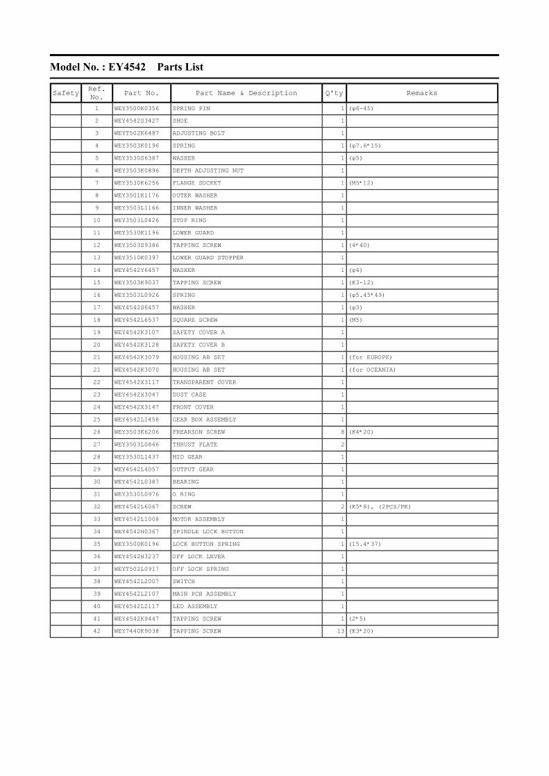
Model No. : EY4542 Parts List
Safety
Ref. No. Part No. Part Name & Description Q'ty Remarks
1 WEY3500K0356 SPRING PIN 1 (φ6-45)
2 WEY4542S3427 SHOE 1
3 WEYT502K6487 ADJUSTING BOLT 1
4 WEY3503K0196 SPRING 1 (φ7.6*15)
5 WEY3530S6387 WASHER 1 (φ5)
6 WEY3503K0896 DEPTH ADJUSTING NUT 1
7 WEY3530K6256 FLANGE SOCKET 1 (M5*12)
8 WEY3501K1176 OUTER WASHER 1
9 WEY3503L1166 INNER WASHER 1
10 WEY3503L0426 STOP RING 1
11 WEY3530K1196 LOWER GUARD 1
12 WEY3503S9386 TAPPING SCREW 1 (4*40)
13 WEY3510K0397 LOWER GUARD STOPPER 1
14 WEY4542Y6457 WASHER 1 (φ4)
15 WEY3503K9037 TAPPING SCREW 1 (K3-12)
16 WEY3503L0926 SPRING 1 (φ5.45*49)
17 WEY4542S6457 WASHER 1 (φ3)
18 WEY4542L6537 SQUARE SCREW 1 (M5)
19 WEY4542K3107 SAFETY COVER A 1
20 WEY4542K3128 SAFETY COVER B 1
21 WEY4542K3079 HOUSING AB SET 1 (for EUROPE)
21 WEY4542K3070 HOUSING AB SET 1 (for OCEANIA)
22 WEY4542X3117 TRANSPARENT COVER 1
23 WEY4542X3047 DUST CASE 1
24 WEY4542X3147 FRONT COVER 1
25 WEY4542L1458 GEAR BOX ASSEMBLY 1
26 WEY3503K6206 FREARSON SCREW 8 (K4*20)
27 WEY3503L0846 THRUST PLATE 2
28 WEY3530L1437 MID GEAR 1
29 WEY4542L4057 OUTPUT GEAR 1
30 WEY4542L0387 BEARING 1
31 WEY3530L0976 O RING 1
32 WEY4542L6067 SCREW 2 (K5*8), (2PCS/PK)
33 WEY4542L1008 MOTOR ASSEMBLY 1
34 WEY4542H0367 SPINDLE LOCK BUTTON 1
35 WEY3500K0196 LOCK BUTTON SPRING 1 (15.4*37)
36 WEY4542H3237 OFF LOCK LEVER 1
37 WEYT502L0917 OFF LOCK SPRING 1
38 WEY4542L2007 SWITCH 1
39 WEY4542L2107 MAIN PCB ASSEMBLY 1
40 WEY4542L2117 LED ASSEMBLY 1
41 WEY4542K9447 TAPPING SCREW 1 (2*5)
42 WEY7440K9038 TAPPING SCREW 13 (K3*20)

Model No. : EY4542 Parts List
Safety
Ref. No. Part No. Part Name & Description Q'ty Remarks
43 WEY4542L9257 TAPPING SCREW 1 (K2*10)
44 WEY3542K7867 HEX WRENCH 1
45 WEY9L40R2788 BATTERY PACK COVER 1
- WEY9642K7018 TOOL CASE 1 <SH>
- WEY9643K7108 SOFT CASE 1 <SH>
- WEY4542K8008 WRAPPER 1 <SH>
- WEY4542K8109 OPERATING INSTRUCTIONS 1 <SH>