corecordic v4.0 handbook - actel. · pdf filecordic engine implements the cordic algorithm...
TRANSCRIPT

CoreCORDIC v4.0 Handbook

Revision History
2 CoreCORDIC v4.0 Handbook
Revision History Date Revision Change 15 June 2015 V6 Sixth release
Confidentiality Status This is a non-confidential document.
CoreCORDIC v4.0 Handbook 3
Table of Contents
Preface ............................................................................................................................ 5 About this Document ..................................................................................................................................... 5 Intended Audience ......................................................................................................................................... 5 References .................................................................................................................................................... 5
Introduction .................................................................................................................... 6 Overview ........................................................................................................................................................ 6 Key Features ................................................................................................................................................. 7 Core Version .................................................................................................................................................. 7 Supported Families ........................................................................................................................................ 7 Device Utilization and Performance .............................................................................................................. 8
Functional Block Description ..................................................................................... 10 Block Diagram ............................................................................................................................................. 10
Core Description .......................................................................................................... 11 Architectures ................................................................................................................................................ 11 Data Path ..................................................................................................................................................... 12
Functional Modes ........................................................................................................ 14 General Vector Rotation .............................................................................................................................. 14 Polar to Rectangular Coordinate Translation .............................................................................................. 14 Rectangular to Polar Coordinate Translation .............................................................................................. 15 Sine and Cosine .......................................................................................................................................... 16 Arctangent ................................................................................................................................................... 16 Function-Dependent Input and Output Values ............................................................................................ 17 Data Formats ............................................................................................................................................... 17
Interface Description ................................................................................................... 19 RTL Parameters/Generics ........................................................................................................................... 19 I/O Ports ....................................................................................................................................................... 20
Tool Flows .................................................................................................................... 22 License ........................................................................................................................................................ 22 SmartDesign ................................................................................................................................................ 22 Simulation Flows .......................................................................................................................................... 23 Synthesis in Libero ....................................................................................................................................... 23 Place-and-Route in Libero ........................................................................................................................... 23
Testbench Operation and Modification ...................................................................... 24

Table of Contents
4 CoreCORDIC v4.0 Handbook
Ordering Information ................................................................................................... 25 Ordering Codes ........................................................................................................................................... 25
Appendix - Four-Quadrant Arctangent Function ...................................................... 26
List of Changes ............................................................................................................ 27
Product Support ........................................................................................................... 28 Customer Service ........................................................................................................................................ 28 Customer Technical Support Center ........................................................................................................... 28 Technical Support ........................................................................................................................................ 28 Website ........................................................................................................................................................ 28 Contacting the Customer Technical Support Center ................................................................................... 28 ITAR Technical Support .............................................................................................................................. 29

CoreCORDIC v4.0 Handbook 5
Preface
About this Document This handbook provides details about Microsemi® CoreCORDIC and how to use it.
Intended Audience Microsemi FPGA designers using Libero® System-on-Chip (SoC) or Libero Integrated Design Environment (IDE).
References
Third Party Publications • Ray Andraka, “A survey of CORDIC algorithms for FPGA based computers“
http://www.andraka.com/files/crdcsrvy.pdf • http://www.dspguru.com/dsp/faqs/cordic • J.S.Walther, “A unified algorithm for elementary functions”
http://www.computer.org/csdl/proceedings/afips/1971/5077/00/50770379.pdf • Clive Maxfield, “Rounding algorithms 101 Redux”
http://www.eetimes.com/document.asp?doc_id=1274515
CoreCORDIC v4.0 Handbook 6
Introduction
Overview CoreCORDIC produces Microsemi field programmable gate array (FPGA)-optimized COordinate Rotation DIgital Computer (CORDIC) logic based on user-defined parameters. The CORDIC algorithm is commonly used for multiplierless vector rotation, conversion from polar to rectangular coordinates and vice-versa, trigonometric function calculation. The IP core can be configured for one of the following functions:
• General vector rotation • Polar to rectangular coordinate translation • Rectangular to polar coordinate translation • Sine and cosine computation • Arctangent computation
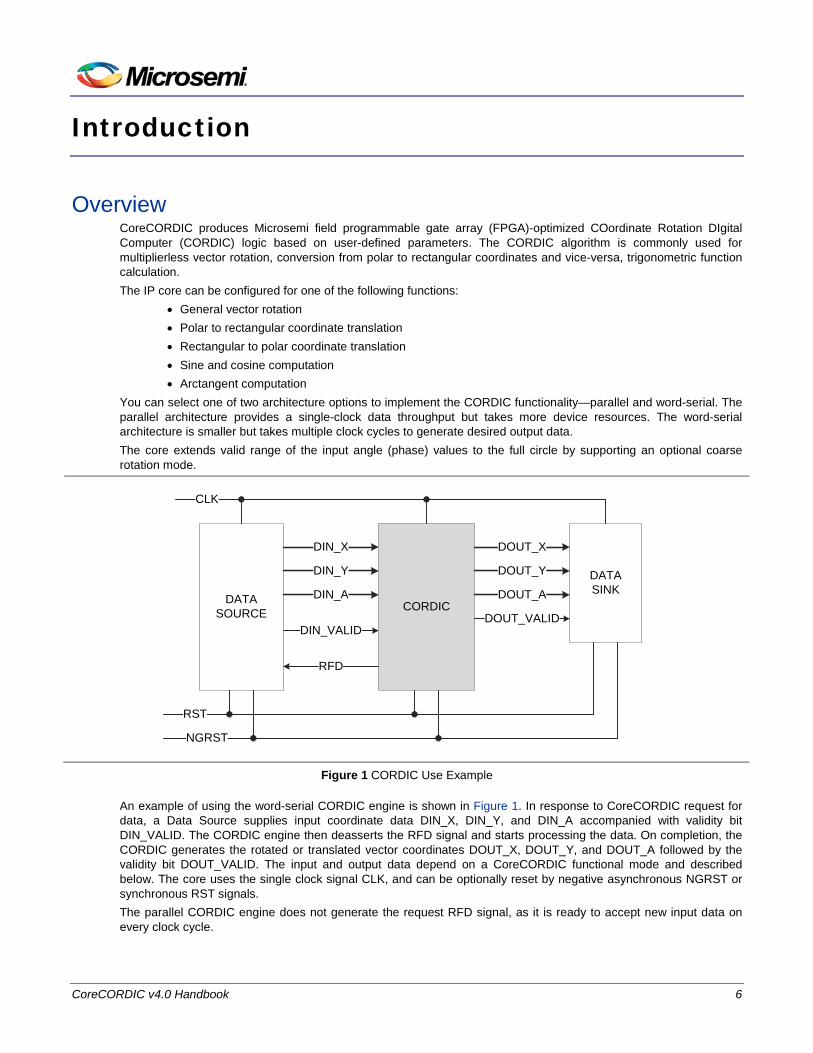
You can select one of two architecture options to implement the CORDIC functionality—parallel and word-serial. The parallel architecture provides a single-clock data throughput but takes more device resources. The word-serial architecture is smaller but takes multiple clock cycles to generate desired output data. The core extends valid range of the input angle (phase) values to the full circle by supporting an optional coarse rotation mode.
CORDICDATA SOURCE
DATA SINK
CLK
DIN_X
DIN_Y
DIN_A
DIN_VALID
DOUT_X
DOUT_VALID
DOUT_Y
DOUT_A
RFD
RST
NGRST
Figure 1 CORDIC Use Example
An example of using the word-serial CORDIC engine is shown in Figure 1. In response to CoreCORDIC request for data, a Data Source supplies input coordinate data DIN_X, DIN_Y, and DIN_A accompanied with validity bit DIN_VALID. The CORDIC engine then deasserts the RFD signal and starts processing the data. On completion, the CORDIC generates the rotated or translated vector coordinates DOUT_X, DOUT_Y, and DOUT_A followed by the validity bit DOUT_VALID. The input and output data depend on a CoreCORDIC functional mode and described below. The core uses the single clock signal CLK, and can be optionally reset by negative asynchronous NGRST or synchronous RST signals. The parallel CORDIC engine does not generate the request RFD signal, as it is ready to accept new input data on every clock cycle.

Key Features
CoreCORDIC v4.0 Handbook 7
Key Features Following are the key features of CoreCORDIC:
• Parameterizable RTL generator • Functional modes: − General vector rotation − Conversion from Polar to Rectangular coordinates − Translation from Rectangular to Polar coordinates − Sine and Cosine calculation − Arctangent (angle) calculation
• Configurable 8 to 48 bits input and output data bit resolution • Automatic or user-controllable precision of internal calculations up to 48 bits • Variety of output rounding options: − Truncation − Convergent rounding (round to nearest even) − Symmetric rounding (round to positive or negative infinity) − Round up (round to positive infinity)
• Word-serial architecture for smaller area • Parallel architecture for high throughput • Configurable number of iterations up to 48 • Synchronous design using a single-clock
Core Version This handbook supports CoreCORDIC v4.0.
Supported Families The CoreCORDIC v4.0 supports the following families:
• SmartFusion®2 • IGLOO®2 • IGLOO® • IGLOOe • IGLOO PLUS • RTG4™ • ProASIC®3 • ProASIC3E • ProASIC3L • ProASICPLUS • SmartFusion® • Fusion • Axcelerator® • RTAX-S/SL and RTAX-DSP

Introduction
8 CoreCORDIC v4.0 Handbook
Device Utilization and Performance CoreCORDIC has been implemented in Microsemi SmartFusion2, RTAX-S, and ProASIC3 devices. The core data are listed in Table 1, Table 2, Table 3, and Table 4. Test configurations are listed in Table 5. In all cases, typical synthesis settings were used. Timing driven high effort five passes layout was used.
Table 1 ·SmartFusion2 Utilization and Performance for the M2S050 Device at Speed Grade -1 Function Architecture Coarse Device Utilization Max Clock
Rate, MHz Transformation
Time, ns 4-LUT DFF
General Rotation Word-serial No 508 300 187.5 90.7
Yes 570 345 170.5 99.7
Parallel No 1053 1066 243.4 4.1
Yes 1147 1105 238 4.2
Rectangular to Polar Conversion
Word-serial No 484 281 185.6 91.6
Yes 616 367 188 90.4
Parallel No 999 1025 243 4.1
Yes 1168 1145 245 4.1
Table 2 RTG4 Utilization and Performance for the RT4G150 Device at Speed Grade -1 Function Architecture Coarse Device Utilization Max Clock
Rate, MHz Transformation
Time, ns 4-LUT DFF
General Rotation Word-serial No 502 298 143.6 118.4
Yes 574 341 145.3 117
Parallel No 1015 1071 199 5
Yes 1111 1110 195 5.1
Rectangular to Polar Conversion
Word-serial No 485 284 143.8 118.2
Yes 602 367 142 119.7
Parallel No 979 1035 216 4.6
Yes 1145 1154 200 5

Device Utilization and Performance
CoreCORDIC v4.0 Handbook 9
Table 3 RTAX-S Utilization and Performance for the RTAX250S Device at Speed Grade -1 Function Architecture Coarse Device Utilization Max Clock
Rate, MHz Transformation
Time, ns Sequential Combinatorial Total
General Rotation
Word-serial No 297 339 636 98.8 172.1
Yes 347 489 836 96.8 175.6
Parallel No 1108 2164 3272 86.7 11.5
Yes 1149 2311 3460 89.1 11.2
Rectangular to Polar Conversion
Word-serial No 275 328 603 98.4 172.8
Yes 382 493 875 95.2 178.6
Parallel No 1092 2098 3190 86.1 11.6
Yes 1215 2302 3517 83.3 12
Table 4 ProASIC3 Utilization and Performance for the A3P600 Device at Speed Grade -2 Function Architecture Coarse Device Utilization Max Clock
Rate, MHz Transformation
Time, ns Sequential Combinatorial Total
General Rotation
Word-serial No 249 930 1179 66.1 257.2
Yes 312 1136 1448 62.8 270.7
Parallel No 1090 4050 5140 81.7 12.2
Yes 1129 4154 5283 83.8 11.9
Rectangular to Polar Conversion
Word-serial No 249 986 1235 63 269.8
Yes 345 1200 1545 64 265.6
Parallel No 1041 3915 4956 81.5 12.3
Yes 1163 4148 5311 85.1 11.8
Table 5 CoreCORDIC Test Configuration Parameter Value
In/Out data width 16 bits
Data Path Control Auto
Number of Iterations 16
Rounding Truncation
HDL language Verilog

CoreCORDIC v4.0 Handbook 10
Functional Block Description
Block Diagram Figure 2 shows the block diagram of CoreCORDIC.
DIN_X
DIN_Y
DIN_A
Coarse Rotator
CORDICEngine
Coarse Post-
RotatorRound
DOUT_X
DOUT_Y
DOUT_A
Arctan LUT
ControlDIN_VALIDDOUT_VALID
RFD
Figure 2 CoreCORDIC Block Diagram
CORDIC engine implements the CORDIC algorithm that calculates trigonometry functions using additions, subtractions, and the pre-computed elementary rotation angle look-up table, Arctan LUT. The CORDIC algorithm works properly when a rotation angle is within the range from –π/2 to π/2. The optional Coarse Rotator puts an arbitrary rotation angle within the valid range. Then the Coarse Post-Rotator applies a similar rotation in the opposite direction thus, negating the coarse vector rotation applied earlier. A bit width of the CORDIC engine arithmetic unit is often larger than a required output bit width. The Round block applies one of four available truncation or rounding techniques to reduce the data width. The word-serial architecture asserts the RFD signal once it calculates a previous vector output. Upon obtaining the DIN_VALID signal, the core deactivates the RFD flag and runs a user-selected number of CORDIC iterations; one iteration per clock cycle. As soon as the core is ready to accept a new input vector, it raises the RFD flag and soon after the DOUT_VALID signal. The parallel architecture does not generate the RFD flag, as it is always ready to accept a new vector. CORDIC algorithm applies a processing gain K. Its value approaches K=1.646760 as the number of iterations goes up. In other words, the CORDIC output vectors are multiplied by the gain factor K.

CoreCORDIC v4.0 Handbook 11
Core Description
Architectures The core implements two CORDIC architectures—word-serial and parallel. You can select the one that suits your overall design needs.
Word-Serial Architecture The word-serial architecture takes relatively small amount of chip resources. It runs CORDIC iterations on the same hardware sequentially, one by one. Every iteration takes a clock cycle. Overall it takes Number of Iterations+3 clock cycles to complete CORDIC computations when coarse rotation is disabled. Figure 3 shows the full computation cycle as a delay between DIN_VALID and DOUT_VALID signals.
RFD
DIN_VALID
DIN_X, DIN_Y, DIN_A
DOUT_VALID
DOUT_X, DOUT_Y, DOUT_A
CLK
Number of Iterations+1Number of Iterations+3
Figure 3 Word-Serial CORDIC Timing (Coarse Rotation Disabled)
Fresh data however, can come to the CORDIC input in Number of Iterations+1 clock cycles that is, by the time when the next RFD signal gets asserted (Figure 3). Thus the minimal distance between consecutive DIN_VALID pulses equals the delay between the DIN_VALID and the next positive edge of the RFD signal. This distance defines the minimal CORDIC cycle for the word-serial architecture. Figure 4 shows the CORDIC delays when coarse rotation enabled. The minimal CORDIC cycle there equals Number of Iterations+2 and the CORDIC delay is Number of Iterations+6.
RFD
DIN_VALID
DIN_X, DIN_Y, DIN_A
DOUT_VALID
DOUT_X, DOUT_Y, DOUT_A
CLK
Number of Iterations+2Number of Iterations+6
Figure 4 Word-Serial Timing (Coarse Rotation Enabled)
The DIN_VALID signals not qualified by active RFD signal are neglected.
Core Description
12 CoreCORDIC v4.0 Handbook
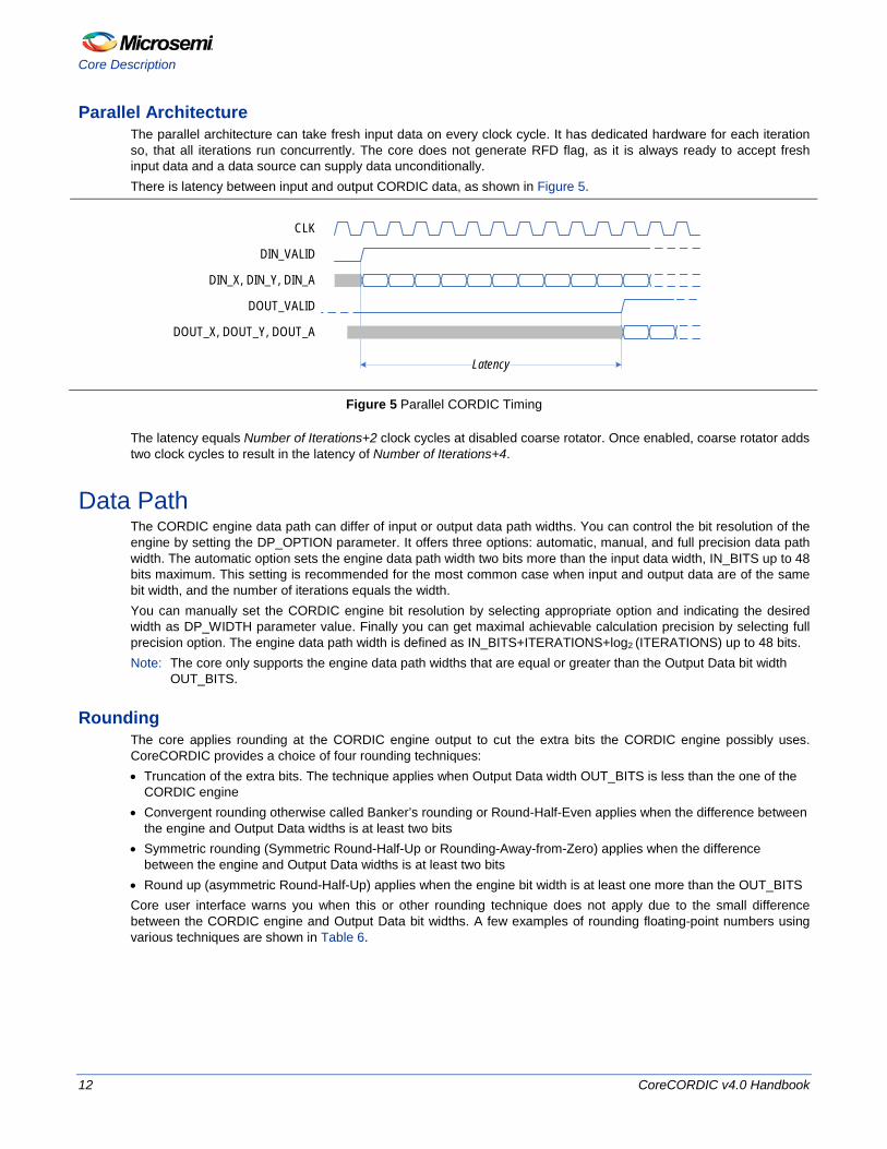
Parallel Architecture The parallel architecture can take fresh input data on every clock cycle. It has dedicated hardware for each iteration so, that all iterations run concurrently. The core does not generate RFD flag, as it is always ready to accept fresh input data and a data source can supply data unconditionally. There is latency between input and output CORDIC data, as shown in Figure 5.
DIN_VALID
DIN_X, DIN_Y, DIN_A
DOUT_VALID
DOUT_X, DOUT_Y, DOUT_A
CLK
Latency
Figure 5 Parallel CORDIC Timing
The latency equals Number of Iterations+2 clock cycles at disabled coarse rotator. Once enabled, coarse rotator adds two clock cycles to result in the latency of Number of Iterations+4.
Data Path The CORDIC engine data path can differ of input or output data path widths. You can control the bit resolution of the engine by setting the DP_OPTION parameter. It offers three options: automatic, manual, and full precision data path width. The automatic option sets the engine data path width two bits more than the input data width, IN_BITS up to 48 bits maximum. This setting is recommended for the most common case when input and output data are of the same bit width, and the number of iterations equals the width. You can manually set the CORDIC engine bit resolution by selecting appropriate option and indicating the desired width as DP_WIDTH parameter value. Finally you can get maximal achievable calculation precision by selecting full precision option. The engine data path width is defined as IN_BITS+ITERATIONS+log2 (ITERATIONS) up to 48 bits. Note: The core only supports the engine data path widths that are equal or greater than the Output Data bit width
OUT_BITS.
Rounding The core applies rounding at the CORDIC engine output to cut the extra bits the CORDIC engine possibly uses. CoreCORDIC provides a choice of four rounding techniques: • Truncation of the extra bits. The technique applies when Output Data width OUT_BITS is less than the one of the
CORDIC engine • Convergent rounding otherwise called Banker’s rounding or Round-Half-Even applies when the difference between
the engine and Output Data widths is at least two bits • Symmetric rounding (Symmetric Round-Half-Up or Rounding-Away-from-Zero) applies when the difference
between the engine and Output Data widths is at least two bits • Round up (asymmetric Round-Half-Up) applies when the engine bit width is at least one more than the OUT_BITS Core user interface warns you when this or other rounding technique does not apply due to the small difference between the CORDIC engine and Output Data bit widths. A few examples of rounding floating-point numbers using various techniques are shown in Table 6.

Data Path
CoreCORDIC v4.0 Handbook 13
Table 6 Rounding Techniques Floating-point number
Truncation Convergent rounding Symmetric rounding Round up
0.7 0 1 1 1
-0.7 -1 -1 -1 -1
1.4 1 1 1 1
-1.4 -2 -1 -1 -1
1.5 1 2 2 2
-1.5 -2 -2 -2 -1
2.5 2 2 3 3
-2.5 -3 -2 -3 -2

CoreCORDIC v4.0 Handbook 14
Functional Modes
The CoreCORDIC v4.0 supports five functional modes.
General Vector Rotation In this mode, the core rotates the input vector (X, Y) by the input angle A to produce the output vector (X’, Y’). Figure 6 shows the vector rotation. Note, the output vector (X’, Y’) is scaled up by the CORDIC gain K. Refer to the Function-Dependent Input and Output Values section for the core input and output data values in this mode.
(X, Y)
(X’, Y’)
A
Figure 6 General Vector Rotation
Polar to Rectangular Coordinate Translation In this functional mode, CoreCORDIC rotates a specific vector with initial ordinate value Y=0. Figure 7 shows the vector rotation. Polar coordinates, magnitude R and angle A get translated into Cartesian pair (X’, Y’):
𝑋𝑋′ = 𝐾𝐾 ∗ 𝑅𝑅 ∗ cos(𝐴𝐴)
EQ1
𝑌𝑌′ = 𝐾𝐾 ∗ 𝑅𝑅 ∗ sin(𝐴𝐴)
EQ2 Note: The output vector (X’, Y’) is scaled up by the CORDIC gain K.
Refer to the Function-Dependent Input and Output Values section for the core input and output data values in this mode.

Rectangular to Polar Coordinate Translation
CoreCORDIC v4.0 Handbook 15
(R, 0)
(X’, Y’)
A
Figure 7 Polar to Rectangular Coordinate Translation
Rectangular to Polar Coordinate Translation In this functional mode, CORDIC rotates the input vector (X, Y) until it aligns with x-axis, refer to Figure 8. A pair of Cartesian coordinates (X, Y) gets translated into magnitude and phase of the vector:
𝑋𝑋′ = 𝐾𝐾 ∗ �𝑋𝑋2 + 𝑌𝑌2
EQ3
𝐴𝐴′ = arctan �𝑌𝑌𝑋𝑋�
EQ4 Note:
1. The output vector (X', 0) is scaled up by the CORDIC gain K. 2. The Equation EQ4 applicable when the input vector (X, Y) is located in the first quadrant. For the full
description, refer to the Appendix - Four-Quadrant Arctangent Function. Refer to the Function-Dependent Input and Output Values section for the core input and output data values in this mode.
(X, Y)
(X’, 0)
A’
Figure 8 Rectangular to Polar Coordinate Translation

Functional Modes
16 CoreCORDIC v4.0 Handbook
Sine and Cosine In this functional mode, the vector rotation is used to calculate sine and cosine values. Provided the input magnitude is set to be R = 1/K, refer to Figure 9. The Vector Rotation equations yield the following values:
𝑋𝑋′ = 𝐾𝐾 ∗1𝐾𝐾∗ 𝑐𝑐𝑐𝑐𝑐𝑐𝑐𝑐 = 𝑐𝑐𝑐𝑐𝑐𝑐𝑐𝑐
EQ5
𝑌𝑌′ = 𝐾𝐾 ∗1𝐾𝐾∗ 𝑐𝑐𝑠𝑠𝑠𝑠𝑐𝑐 = 𝑐𝑐𝑠𝑠𝑠𝑠𝑐𝑐
EQ6 The core automatically supplies the magnitude value of 1/K to the DIN_X input as well, as 0 to the DIN_Y input. Only the angle argument A needs to be provided to the core. In the Sine and Cosine mode, the results are not scaled by the CORDIC gain factor.
Refer to the Function-Dependent Input and Output Values section for the core input and output data values in this mode.
(1/K, 0)
(X’, Y’)
A
Figure 9 Sine and Cosine Functional Mode
Arctangent The Arctangent function is similar to the Rectangular to Polar translation. It only outputs the arctangent value, which does not introduce the CORDIC gain. Refer to the Function-Dependent Input and Output Values section for the core input and output data values in this mode.

Function-Dependent Input and Output Values
CoreCORDIC v4.0 Handbook 17
Function-Dependent Input and Output Values Table 7 shows CoreCORDIC input and output signal meanings in every functional mode. K denotes the CORDIC processing gain. Table 7 shows the available data inputs and outputs in every functional mode, in bold.
Table 7 ·CORDIC Input and Output Values
Functional Mode CORDIC Input Values CORDIC Output Values
General Rotation DIN_X: Abscissa X DOUT_X = K*(X*cos(A) – Y*sin(A))
DIN_Y: Ordinate Y DOUT_Y = K*(Y*cos(A) + X*sin(A))
DIN_A: Angle A DOUT_A = No meaning
Polar to Rectangular Translation
DIN_X: Magnitude R DOUT_X = K*R*cos(A)
DIN_Y: 0 DOUT_Y = K*R*sin(A)
DIN_A: Angle A DOUT_A = No meaning
Rectangular to Polar Translation
DIN_X: Abscissa X DOUT_X = K*sqrt(X2 + Y2)
DIN_Y: Ordinate Y DOUT_Y = No meaning
DIN_A: 0 DOUT_A = arctan(Y/X)
Sine and Cosine DIN_X: 0 DOUT_X = cos(A)
DIN_Y: 0 DOUT_Y = sin(A)
DIN_A: Angle A DOUT_A = No meaning
Arctangent DIN_X: Abscissa X DOUT_X = No meaning
DIN_Y: Ordinate Y DOUT_Y = No meaning
DIN_A: 0 DOUT_A = arctan(Y/X)
Data Formats CoreCORDIC uses different data formats for linear (X and Y) and angular (A) data.
Linear Formats The CORDIC input data signals in the floating-point domain must be in the range [-1.0; 1.0]. An input signal that falls outside of the range can produce incorrect results. CoreCORDIC accepts fixed-point IN_BITS-wide input signals DIN_X and DIN_Y with the most significant bit (MSB) representing the sign and the next bit representing the integer part of the input signal. Conversion from floating to fixed-point follows the formula:
Fixed-point X = 2IN_BITS-2*Floating-point x
EQ7 The following examples show the correspondence between floating and fixed-point numbers at IN_BITS = 10: 1.0 <> 01.00000000 <> “01 0000 0000” -1.0 <> 11.00000000 <> “11 0000 0000” 0.75 <> 00.11000000 <> “00 1100 0000” -0.75 <> 11.01000000 <> “11 0100 0000” 0.25 <> 00.01000000 <> “00 0100 0000” -0.25 <> 11.11000000 <> “11 1100 0000” 0.1 <> 00.00011010 <> “00 0001 1010” -0.1 <> 11.11100110 <> “11 1110 0110”

Functional Modes
18 CoreCORDIC v4.0 Handbook
Due to the CORDIC algorithm’s gain, the output linear data (DOUT_X, DOUT_Y) signal range is approximately [-2.32; 2.32]. This requires a different fixed-point format capable of representing the wider range. The MSB of the output linear data identifies the sign, and the next two bits represent the integer part of the output signal. Conversion from linear output fixed-point format to floating point follows the formula:
Floating-point xout = Fixed-point Xout/2OUT_BITS-3
EQ8
The following example show the correspondence between floating and fixed-point numbers at OUT_BITS = 10: “01 0010 1001” <> 010.0101001 <> 2.32 “10 1101 0111” <> 101.1010111 <> -2.32 “01 0000 0000” <> 010.0000000 <> 2.0 “11 0000 0000 <> 110.0000000 <> -2.0 “00 1000 0000 <> 001.0000000 <> 1.0 “11 1000 0000 <> 111.0000000 <> -1.0 “00 0100 0000 <> 000.1000000 <> 0.5 “11 1100 0000 <> 111.1000000 <> -0.5 “00 0000 1101 <> 000.0001101 <> 0.1 “11 1111 0011 <> 111.1110011 <> -0.1
Angular Format The CORDIC input angle in the floating-point domain must be in the range [-π; π] when coarse rotator is enabled. With disabled coarse rotator, the valid angular range is [-π/2; π/2]. Output range for the angular data is the same. CoreCORDIC uses a single fixed-point angular format for input and output angle signals DIN_A and DOUT_A. The input and output angles are expressed as a fraction of π, that is the angle value of 1.0 represents π, value of 0.5 represents π/2, etc. The fixed-point MSB identifies the angle sign, and the next bit presents the integer part of the angle. Angle conversion from floating to fixed-point follows the formula:
Fixed-point A = 2IN_BITS-2 * Floating-point a / π
EQ9 Where, Floating-point a is expressed in radians. The following examples show the correspondence between floating and fixed-point angles at IN_BITS=10 or OUT_BITS=10: π <> 01.00000000 <> “01 0000 0000” -π <> 11.00000000 <> “11 0000 0000” 0.75*π <> 00.11000000 <> “00 1100 0000” -0.75*π <> 11.01000000 <> “11 0100 0000” 0.5*π <> 00.10000000 <> “00 1000 0000” -0.5*π <> 11.10000000 <> “11 1000 0000” 0.25*π <> 00.01000000 <> “00 0100 0000” -0.25*π <> 11.11000000 <> “11 1100 0000” 0.1*π <> 00.00011010 <> “00 0001 1010” -0.1*π <> 11.11100110 <> “11 1110 0110”
CoreCORDIC v4.0 Handbook 19
Interface Description
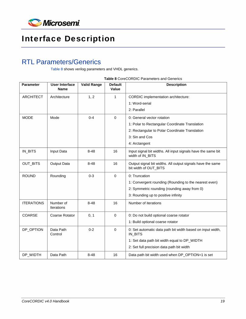
RTL Parameters/Generics Table 8 shows verilog parameters and VHDL generics.
Table 8 CoreCORDIC Parameters and Generics Parameter User Interface
Name Valid Range Default
Value Description
ARCHITECT Architecture 1, 2 1 CORDIC implementation architecture:
1: Word-serial
2: Parallel
MODE Mode 0-4 0 0: General vector rotation
1: Polar to Rectangular Coordinate Translation
2: Rectangular to Polar Coordinate Translation
3: Sin and Cos
4: Arctangent
IN_BITS Input Data 8-48 16 Input signal bit widths. All input signals have the same bit width of IN_BITS
OUT_BITS Output Data 8-48 16 Output signal bit widths. All output signals have the same bit width of OUT_BITS
ROUND Rounding 0-3 0 0: Truncation
1: Convergent rounding (Rounding to the nearest even)
2: Symmetric rounding (rounding away from 0)
3: Rounding up to positive infinity
ITERATIONS Number of Iterations
8-48 16 Number of iterations
COARSE Coarse Rotator 0, 1 0 0: Do not build optional coarse rotator
1: Build optional coarse rotator
DP_OPTION Data Path Control
0-2 0 0: Set automatic data path bit width based on input width, IN_BITS
1: Set data path bit width equal to DP_WIDTH
2: Set full precision data path bit width
DP_WIDTH Data Path 8-48 16 Data path bit width used when DP_OPTION=1 is set
Interface Description
20 CoreCORDIC v4.0 Handbook
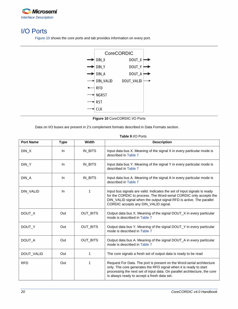
I/O Ports Figure 10 shows the core ports and tab provides information on every port.
CoreCORDICDIN_X
DIN_Y
DIN_A
DIN_VALID
NGRST
RST
DOUT_X
DOUT_Y
DOUT_A
DOUT_VALID
RFD
CLK
Figure 10 CoreCORDIC I/O Ports
Data on I/O buses are present in 2’s complement formats described in Data Formats section.
Table 9 I/O Ports Port Name Type Width Description
DIN_X In IN_BITS Input data bus X. Meaning of the signal X in every particular mode is described in Table 7
DIN_Y In IN_BITS Input data bus Y. Meaning of the signal Y in every particular mode is described in Table 7
DIN_A In IN_BITS Input data bus A. Meaning of the signal A in every particular mode is described in Table 7
DIN_VALID In 1 Input bus signals are valid. Indicates the set of input signals is ready for the CORDIC to process. The Word-serial CORDIC only accepts the DIN_VALID signal when the output signal RFD is active. The parallel CORDIC accepts any DIN_VALID signal.
DOUT_X Out OUT_BITS Output data bus X. Meaning of the signal DOUT_X in every particular mode is described in Table 7
DOUT_Y Out OUT_BITS Output data bus Y. Meaning of the signal DOUT_Y in every particular mode is described in Table 7
DOUT_A Out OUT_BITS Output data bus A. Meaning of the signal DOUT_A in every particular mode is described in Table 7
DOUT_VALID Out 1 The core signals a fresh set of output data is ready to be read
RFD Out 1 Request For Data. The port is present on the Word-serial architecture only. The core generates the RFD signal when it is ready to start processing the next set of input data. On parallel architecture, the core is always ready to accept a fresh data set.

I/O Ports
CoreCORDIC v4.0 Handbook 21
Port Name Type Width Description
CLK In 1 System clock with active positive edge
NGRST In 1 Optional asynchronous reset. Resets all registers and state machines. At least one of the two signals, NGRST or RST need to be supplied after powering on an FPGA device.
RST In 1 Optional synchronous reset. Resets all registers and state machines. At least one of the two signals, NGRST or RST need to be supplied after powering on an FPGA device.

CoreCORDIC v4.0 Handbook 22
Tool Flows
License CoreCORDIC is included in the Libero catalog and does not require a separate license to be instantiated and used in the Microsemi devices. Complete source code and a user testbench are provided for the core.
RTL Complete RTL source code is provided for the core.
SmartDesign CoreCORDIC is available for download to the Libero IP catalog through the web repository. Once it is listed on the catalog, the core can be instantiated using the SmartDesign flow. Figure 11 shows an example of instantiated CoreCORDIC.
Figure 11 SmartDesign CoreCORDIC Instance View

Simulation Flows
CoreCORDIC v4.0 Handbook 23
The core can be configured using the configuration window in the SmartDesign, as shown in Figure 12. For information on using the SmartDesign to configure, connect, and generate cores, refer to the Libero online help.
Figure 12 SmartDesign CoreCORDIC Configuration Window
Simulation Flows To run simulations, select the User Testbench in the core configuration interface. Along with generating the core, the Libero installs the pre-synthesis testbench HDL files. Set the design root to a top-level component of the core. Then run the simulation tool from the Libero Design Flow pane
Synthesis in Libero To run synthesis on the core, set the design root to the SmartDesign component instance and run the synthesis tool from the Libero software Design Flow pane.
Place-and-Route in Libero After the design has been synthesized, run Compile and then place-and-route tools.
CoreCORDIC v4.0 Handbook 24
Testbench Operation and Modification
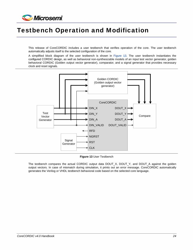
This release of CoreCORDIC includes a user testbench that verifies operation of the core. The user testbench automatically adjusts itself to the selected configuration of the core. A simplified block diagram of the user testbench is shown in Figure 13. The user testbench instantiates the configured CORDIC design, as well as behavioral non-synthesizable models of an input test vector generator, golden behavioral CORDIC (Golden output vector generator), comparator, and a signal generator that provides necessary clock and reset signals.
CoreCORDIC
DIN_X
DIN_Y
DIN_A
DIN_VALID
NGRST
RST
DOUT_X
DOUT_Y
DOUT_A
DOUT_VALID
RFD
CLK
Test Vector
Generator
Signal Generator
Golden CORDIC(Golden output vector
generator)
Compare
Figure 13 User Testbench
The testbench compares the actual CORDIC output data DOUT_X, DOUT_Y, and DOUT_A against the golden output vectors. In case of mismatch during simulation, it prints out an error message. CoreCORDIC automatically generates the Verilog or VHDL testbench behavioral code based on the selected core language.

CoreCORDIC v4.0 Handbook 25
Ordering Information
Ordering Codes CoreCORDIC can be ordered through your local Microsemi sales representative. It should be ordered using the following numbering scheme: CoreCORDIC-XX, where XX is listed in Table 10.
Table 10 Ordering Codes XX Description RM RTL for RTL source — Multiple-use license Note: CoreCORDIC-RM is included free in the Libero software Catalog if you have a valid Libero software license.

CoreCORDIC v4.0 Handbook 26
Appendix - Four-Quadrant Arctangent Function
In the Coarse mode (COARSE=1), CoreCORDIC implements the full circle Rectangular to Polar Coordinate Translation Conversion where the vector phase is defined as four-quadrant arctangent similar to atan2 function found in C and Matlab. The first quadrant vector phase indicates:
arctanq1 = arctan(Y/X)
EQ10 Then CoreCORDIC calculates the phases of the vectors in the other quadrants as follows:
arctanq2 = π - arctanq1
EQ11
arctanq3 = -π + arctanq1
EQ12
arctanq4 = - arctanq1
EQ13 Figure 14 shows examples of the four-quadrant arctangent calculations.
Aarctan(0.3/-0.2) = 2.159 rad = 123.70
Aarctan(-0.3/0.2) =
-0.983 rad = -56.30
(0.2, -0.3)
(-0.2, 0.3)
Aarctan(0.3/0.2) = 0.983 rad = 56.30
(0.2, 0.3)
A
arctan(-0.3/-0.2) = -2.159 rad = -123.70
(-0.2, -0.3)
Figure 14 Examples of Four-Quadrant Phase Calculations

CoreCORDIC v4.0 Handbook 27
List of Changes
The following table shows important changes made in this document for each revision. Date Change Page
Revision 6 (June 2015)
Updated the document as per the new HB specifications. NA

CoreCORDIC v4.0 Handbook 28
Product Support
Microsemi SoC Products Group backs its products with various support services, including Customer Service, Customer Technical Support Center, a website, electronic mail, and worldwide sales offices. This appendix contains information about contacting Microsemi SoC Products Group and using these support services.
Customer Service Contact Customer Service for non-technical product support, such as product pricing, product upgrades, update information, order status, and authorization.
From North America, call 800.262.1060 From the rest of the world, call 650.318.4460 Fax, from anywhere in the world 650. 318.8044
Customer Technical Support Center Microsemi SoC Products Group staffs its Customer Technical Support Center with highly skilled engineers who can help answer your hardware, software, and design questions about Microsemi SoC Products. The Customer Technical Support Center spends a great deal of time creating application notes, answers to common design cycle questions, documentation of known issues and various FAQs. So, before you contact us, please visit our online resources. It is very likely we have already answered your questions.
Technical Support For Microsemi SoC Products Support, visit http://www.microsemi.com/products/fpga-soc/design-support/fpga-soc-support.
Website You can browse a variety of technical and non-technical information on the Microsemi SoC Products Group home page, at http://www.microsemi.com/soc/.
Contacting the Customer Technical Support Center Highly skilled engineers staff the Technical Support Center. The Technical Support Center can be contacted by email or through the Microsemi SoC Products Group website.
Email You can communicate your technical questions to our email address and receive answers back by email, fax, or phone. Also, if you have design problems, you can email your design files to receive assistance. We constantly monitor the email account throughout the day. When sending your request to us, please be sure to include your full name, company name, and your contact information for efficient processing of your request. The technical support email address is [email protected].
My Cases Microsemi SoC Products Group customers may submit and track technical cases online by going to My Cases.
ITAR Technical Support
CoreCORDIC v4.0 Handbook 29
Outside the U.S. Customers needing assistance outside the US time zones can either contact technical support via email ([email protected]) or contact a local sales office. Sales office listings can be found at www.microsemi.com/soc/company/contact/default.aspx.
ITAR Technical Support For technical support on RH and RT FPGAs that are regulated by International Traffic in Arms Regulations (ITAR), contact us via [email protected]. Alternatively, within My Cases, select Yes in the ITAR drop-down list. For a complete list of ITAR-regulated Microsemi FPGAs, visit the ITAR web page.

CoreCORDIC v4.0 Handbook
Microsemi Corporation (MSCC) offers a comprehensive portfolio of semiconductor and system solutions for communications, defense & security, aerospace and industrial markets. Products include high-performance and radiation-hardened analog mixed-signal integrated circuits, FPGAs, SoCs and ASICs; power management products; timing and synchronization devices and precise time solutions, setting the world’s standard for time; voice processing devices; RF solutions; discrete components; security technologies and scalable anti-tamper products; Ethernet solutions; Power-over-Ethernet ICs and midspans; as well as custom design capabilities and services. Microsemi is headquartered in Aliso Viejo, Calif., and has approximately 3,600 employees globally. Learn more at www.microsemi.com.
© 2015 Microsemi Corporation. All rights reserved. Microsemi and the Microsemi logo are trademarks of Microsemi Corporation. All other trademarks and service marks are the property of their respective owners.
Microsemi Corporate Headquarters One Enterprise, Aliso Viejo, CA 92656 USA
Within the USA: +1 (800) 713-4113 Outside the USA: +1 (949) 380-6100 Sales: +1 (949) 380-6136 Fax: +1 (949) 215-4996
E-mail: [email protected]
Microsemi makes no warranty, representation, or guarantee regarding the information contained herein or the suitability of its products and services for any particular purpose, nor does Microsemi assume any liability whatsoever arising out of the application or use of any product or circuit. The products sold hereunder and any other products sold by Microsemi have been subject to limited testing and should not be used in conjunction with mission-critical equipment or applications. Any performance specifications are believed to be reliable but are not verified, and Buyer must conduct and complete all performance and other testing of the products, alone and together with, or installed in, any end-products. Buyer shall not rely on any data and performance specifications or parameters provided by Microsemi. It is the Buyer’s responsibility to independently determine suitability of any products and to test and verify the same. The information provided by Microsemi hereunder is provided “as is, where is” and with all faults, and the entire risk associated with such information is entirely with the Buyer. Microsemi does not grant, explicitly or implicitly, to any party any patent rights, licenses, or any other IP rights, whether with regard to such information itself or anything described by such information. Information provided in this document is proprietary to Microsemi, and Microsemi reserves the right to make any changes to the information in this document or to any products and services at any time without notice.
50200090-6/06.15