coretech system co., ltd. │ copyright© 2021 moldex3d. all
TRANSCRIPT
CoreTech System Co., Ltd. │ Copyright© 2021 Moldex3D. All rights reserved.
Biuro konstrukcyjne PawForm
Micromechanics Interface
CoreTech System Co., Ltd. │ Copyright© 2021 Moldex3D. All rights reserved.No contents are construed as providing a warranty, including any warranty of merchantability, accuracy, completeness, or fitness for purpose, or representation for which CoreTech System Co., Ltd. assumes any legal responsibility.
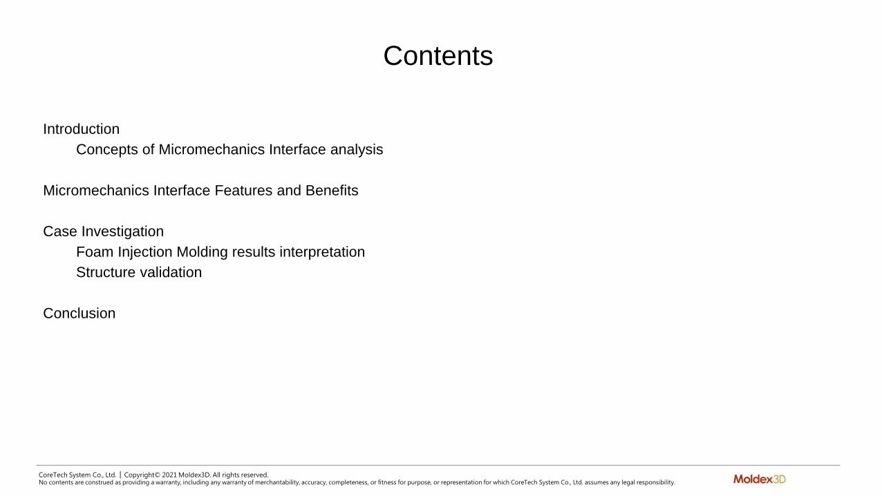
Contents
Introduction
Concepts of Micromechanics Interface analysis
Micromechanics Interface Features and Benefits
Case Investigation
Foam Injection Molding results interpretation
Structure validation
Conclusion

CoreTech System Co., Ltd. │ Copyright© 2021 Moldex3D. All rights reserved.No contents are construed as providing a warranty, including any warranty of merchantability, accuracy, completeness, or fitness for purpose, or representation for which CoreTech System Co., Ltd. assumes any legal responsibility.
Introduction

CoreTech System Co., Ltd. │ Copyright© 2021 Moldex3D. All rights reserved.No contents are construed as providing a warranty, including any warranty of merchantability, accuracy, completeness, or fitness for purpose, or representation for which CoreTech System Co., Ltd. assumes any legal responsibility.
Why Micromechanics Interface
More considerations for nonlinear multi-scale material modeling simulation with integration of Digimat or Converse into FEA software
Provide more efficient and accurate structural analysis of composite materials
Give users an opportunity to solve complex nonlinear multi-scale finite element problems
Micromechanics Interface
Composite material
analysis
FEA software
Nonlinear analysis

CoreTech System Co., Ltd. │ Copyright© 2021 Moldex3D. All rights reserved.No contents are construed as providing a warranty, including any warranty of merchantability, accuracy, completeness, or fitness for purpose, or representation for which CoreTech System Co., Ltd. assumes any legal responsibility.
What Micromechanics Interface can Simulate
Some unique material properties can be considered into the multi-scale model
■ Anisotropic, corresponding to the microstructure morphology
■ Heterogeneous, corresponding to the microstructure morphology
■ Nonlinear, elasto-plastic
■ Fatigue
■ Failure
■ Strain-Rate dependent, visco-elastic

CoreTech System Co., Ltd. │ Copyright© 2021 Moldex3D. All rights reserved.No contents are construed as providing a warranty, including any warranty of merchantability, accuracy, completeness, or fitness for purpose, or representation for which CoreTech System Co., Ltd. assumes any legal responsibility.
Micromechanics Analysis Procedure
Moldex3D E.g. ANSYS / ABAQUS / LS-DYNA
Foaming
*Foam Injection Molding supports Digimat only
LS-DYNA

CoreTech System Co., Ltd. │ Copyright© 2021 Moldex3D. All rights reserved.No contents are construed as providing a warranty, including any warranty of merchantability, accuracy, completeness, or fitness for purpose, or representation for which CoreTech System Co., Ltd. assumes any legal responsibility.
Features and Benefits
CoreTech System Co., Ltd. │ Copyright© 2021 Moldex3D. All rights reserved.No contents are construed as providing a warranty, including any warranty of merchantability, accuracy, completeness, or fitness for purpose, or representation for which CoreTech System Co., Ltd. assumes any legal responsibility.
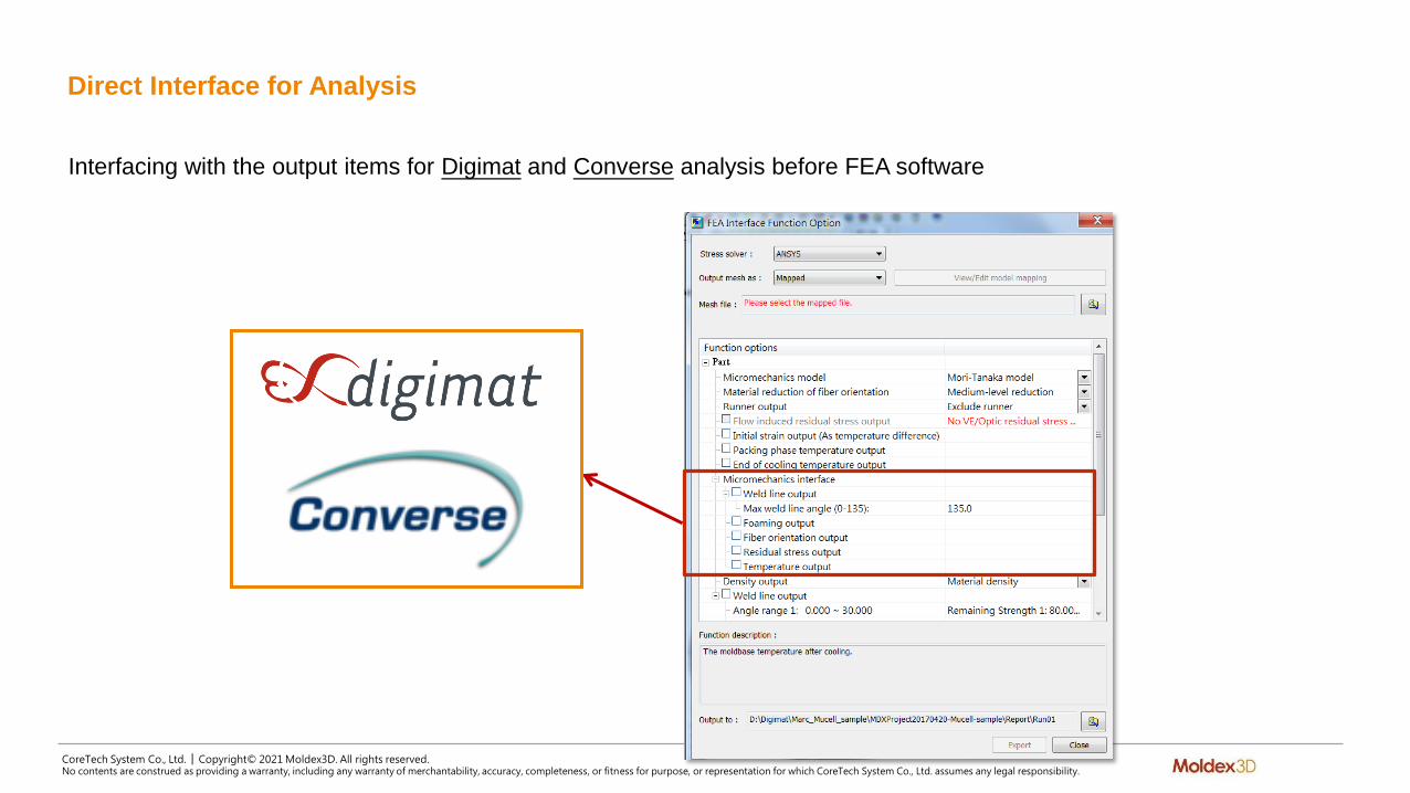
Direct Interface for Analysis
Interfacing with the output items for Digimat and Converse analysis before FEA software

CoreTech System Co., Ltd. │ Copyright© 2021 Moldex3D. All rights reserved.No contents are construed as providing a warranty, including any warranty of merchantability, accuracy, completeness, or fitness for purpose, or representation for which CoreTech System Co., Ltd. assumes any legal responsibility.
Supported Output Files Function Items
DescriptionFile
name
Weld line
Weld line definitions are imported in Digimat-MAP in the form of node sets. This allow to export these sets to CAE codes, using proper element set definition, in order to assign them particular material properties.
*.nwd
Fiber orientation
Export the fiber orientation data for further analysis to view characteristics of fiber.
*.o2d
Flow-inducedresidual stress
When the mold opens to extract the part, those residual stress induce part deformations. Digimat-MAP is there to map such data input and allow to account for it as inputs of mechanical simulations.
*.s2d
Temperature
Temperatures before this cooling step could then be exported from the injection simulation results to Digimat-MAP. Digimat-MAP allows to map those temperatures from the injection mesh onto the structural mesh in order to perform a warpage analysis in CAE simulation software.
*.t2d
Foaming
Export the cell size and cell density data for
analysis to observe the mechanical properties
of foaming structure. Digimat-MF and
Digimat-CAE can transform the element modulus.
*.m2d
Note: Converse supports *.o2d (Fiber orientation output) ONLY

CoreTech System Co., Ltd. │ Copyright© 2021 Moldex3D. All rights reserved.No contents are construed as providing a warranty, including any warranty of merchantability, accuracy, completeness, or fitness for purpose, or representation for which CoreTech System Co., Ltd. assumes any legal responsibility.
Options of Digimat Output
Support Digimat output for ANSYS, ABAQUS, MSC-Nastran, Marc, LS-DYNA and Optistruct
To cover complete process-induced variation during the molding processes, the output items include:
■ Fiber orientation
■ Weld line region data
■ Residual stress
• Digimat-MAP allows to map the residual stress data and account it as input of mechanical simulations
■ Temperature distribution at EOP and EOC
• Include part and part insert object
• Temperature before and after the cooling step could be used to perform warpage analysis by Digimat
Benefit
Users can determine more molding process-induced results and apply it into micromechanics consideration

CoreTech System Co., Ltd. │ Copyright© 2021 Moldex3D. All rights reserved.No contents are construed as providing a warranty, including any warranty of merchantability, accuracy, completeness, or fitness for purpose, or representation for which CoreTech System Co., Ltd. assumes any legal responsibility.
Option of Digimat Output for Foam Injection Molding Analysis
A new workflow for foam injection molding part structural performance evaluation
Moldex3D can output cell size and cell density to Digimat
Benefit
Completely consider the cell size and cell density in foam injection molding parts

CoreTech System Co., Ltd. │ Copyright© 2021 Moldex3D. All rights reserved.No contents are construed as providing a warranty, including any warranty of merchantability, accuracy, completeness, or fitness for purpose, or representation for which CoreTech System Co., Ltd. assumes any legal responsibility.
Case Investigation 1 Foam Injection Molding Results Interpretation
CoreTech System Co., Ltd. │ Copyright© 2021 Moldex3D. All rights reserved.No contents are construed as providing a warranty, including any warranty of merchantability, accuracy, completeness, or fitness for purpose, or representation for which CoreTech System Co., Ltd. assumes any legal responsibility.
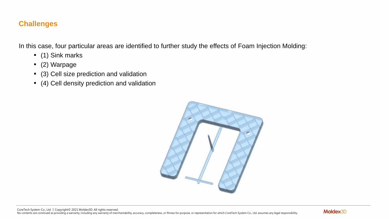
Challenges
In this case, four particular areas are identified to further study the effects of Foam Injection Molding:
■ (1) Sink marks
■ (2) Warpage
■ (3) Cell size prediction and validation
■ (4) Cell density prediction and validation

CoreTech System Co., Ltd. │ Copyright© 2021 Moldex3D. All rights reserved.No contents are construed as providing a warranty, including any warranty of merchantability, accuracy, completeness, or fitness for purpose, or representation for which CoreTech System Co., Ltd. assumes any legal responsibility.
Specific Features
Specific features are added to the part design to further help evaluate, measure, and compare results
Different surface properties(mirror polishing, textures)
Ribs
Max rib-wall ratio 2:1
References for measurements
U-shape to amplify the deformations
Holes to generate weld lines

CoreTech System Co., Ltd. │ Copyright© 2021 Moldex3D. All rights reserved.No contents are construed as providing a warranty, including any warranty of merchantability, accuracy, completeness, or fitness for purpose, or representation for which CoreTech System Co., Ltd. assumes any legal responsibility.
Cell Size Prediction and Validation
SEM validation:
average cell size 77 µm
SEM validation:
average cell size 58 µm
At the end of flow area, the material has travelled the
entire path which allows the cell to grow; also, the
pressure at the flow front is low and makes no
constraints on the growth of bubbles.
It is observed in both simulation and SEM validation
that the large cells are formed. Also, the cell sizes may
vary in different parts of this region.
CoreTech System Co., Ltd. │ Copyright© 2021 Moldex3D. All rights reserved.No contents are construed as providing a warranty, including any warranty of merchantability, accuracy, completeness, or fitness for purpose, or representation for which CoreTech System Co., Ltd. assumes any legal responsibility.
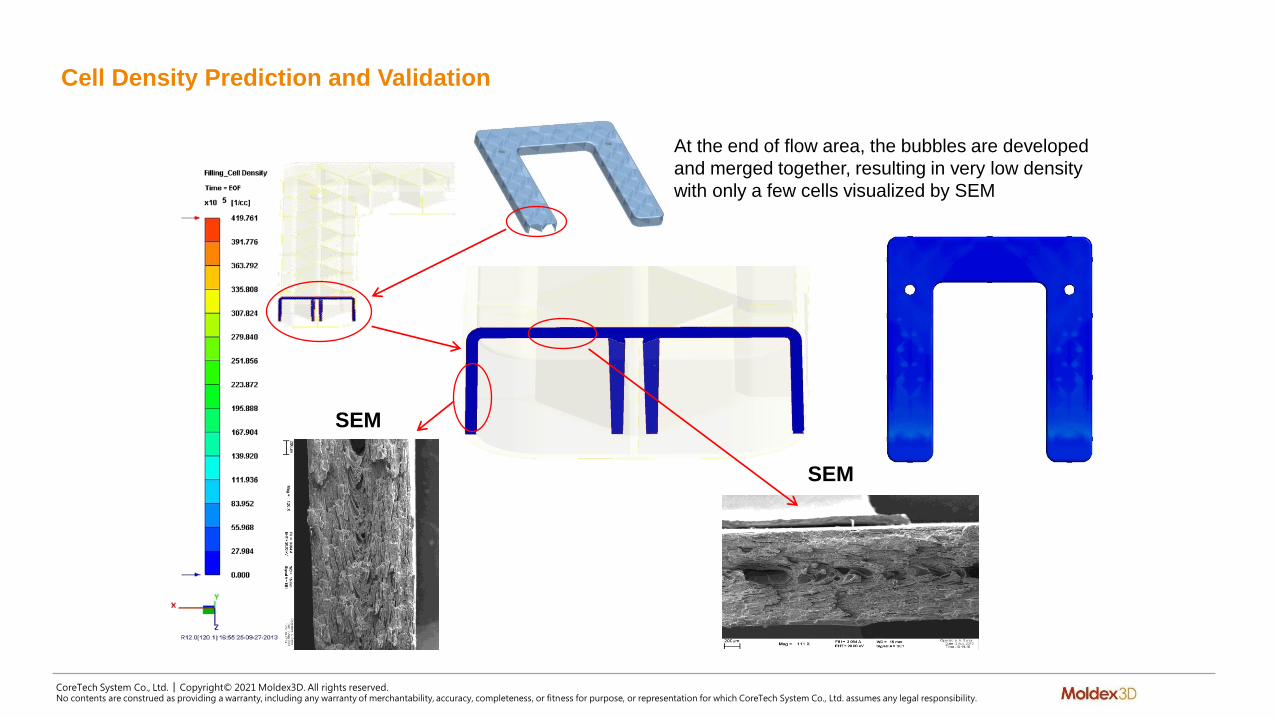
Cell Density Prediction and Validation
SEM
SEM
At the end of flow area, the bubbles are developed
and merged together, resulting in very low density
with only a few cells visualized by SEM
CoreTech System Co., Ltd. │ Copyright© 2021 Moldex3D. All rights reserved.No contents are construed as providing a warranty, including any warranty of merchantability, accuracy, completeness, or fitness for purpose, or representation for which CoreTech System Co., Ltd. assumes any legal responsibility.
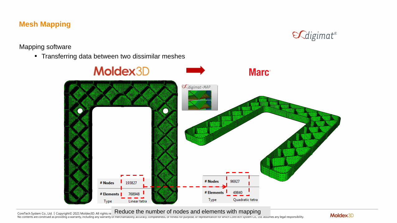
Mesh Mapping
Mapping software
■ Transferring data between two dissimilar meshes
Reduce the number of nodes and elements with mapping

CoreTech System Co., Ltd. │ Copyright© 2021 Moldex3D. All rights reserved.No contents are construed as providing a warranty, including any warranty of merchantability, accuracy, completeness, or fitness for purpose, or representation for which CoreTech System Co., Ltd. assumes any legal responsibility.
Data Mapping
Users can map the density, size, volume of porosity from Moldex3D onto Marc
Density of porosity Size of porosity Volume Fraction of porosity

CoreTech System Co., Ltd. │ Copyright© 2021 Moldex3D. All rights reserved.No contents are construed as providing a warranty, including any warranty of merchantability, accuracy, completeness, or fitness for purpose, or representation for which CoreTech System Co., Ltd. assumes any legal responsibility.
Physical Test Case 1
Accurately predict mechanical behaviour
The force-displacement curve of simulation is very close to that of experiment

CoreTech System Co., Ltd. │ Copyright© 2021 Moldex3D. All rights reserved.No contents are construed as providing a warranty, including any warranty of merchantability, accuracy, completeness, or fitness for purpose, or representation for which CoreTech System Co., Ltd. assumes any legal responsibility.
Physical Test Case 2
Accurately predict mechanical behaviour
The force-displacement curve of simulation is very close to that of experiment

CoreTech System Co., Ltd. │ Copyright© 2021 Moldex3D. All rights reserved.No contents are construed as providing a warranty, including any warranty of merchantability, accuracy, completeness, or fitness for purpose, or representation for which CoreTech System Co., Ltd. assumes any legal responsibility.
Physical Test Case 3
Accurately predict mechanical behaviour
The force-displacement curve of simulation is very close to that of experiment
CoreTech System Co., Ltd. │ Copyright© 2021 Moldex3D. All rights reserved.No contents are construed as providing a warranty, including any warranty of merchantability, accuracy, completeness, or fitness for purpose, or representation for which CoreTech System Co., Ltd. assumes any legal responsibility.
Summary
Moldex3D Foam Injection Molding is not only able to calculate the nucleation and growth of microcellular bubbles, microcellular bubble size, number, density distribution, volumetric shrinkage, but predict the effects of bubble structure onpart warpage
Through Micromechanics Interface, the density, size, volume of cell are all considered into the structural analysis to make the results closer to the reality

CoreTech System Co., Ltd. │ Copyright© 2021 Moldex3D. All rights reserved.No contents are construed as providing a warranty, including any warranty of merchantability, accuracy, completeness, or fitness for purpose, or representation for which CoreTech System Co., Ltd. assumes any legal responsibility.
Case Investigation 2 Structure Validation

CoreTech System Co., Ltd. │ Copyright© 2021 Moldex3D. All rights reserved.No contents are construed as providing a warranty, including any warranty of merchantability, accuracy, completeness, or fitness for purpose, or representation for which CoreTech System Co., Ltd. assumes any legal responsibility.
Model Information
PP with 30% GF

CoreTech System Co., Ltd. │ Copyright© 2021 Moldex3D. All rights reserved.No contents are construed as providing a warranty, including any warranty of merchantability, accuracy, completeness, or fitness for purpose, or representation for which CoreTech System Co., Ltd. assumes any legal responsibility.
Weld Line Prediction
Two gates lead to the generation of weld line in the middle area
Weld line

CoreTech System Co., Ltd. │ Copyright© 2021 Moldex3D. All rights reserved.No contents are construed as providing a warranty, including any warranty of merchantability, accuracy, completeness, or fitness for purpose, or representation for which CoreTech System Co., Ltd. assumes any legal responsibility.
Fiber Orientation Prediction
The fiber orientation is highly aligned along the Y-direction in the middle area

CoreTech System Co., Ltd. │ Copyright© 2021 Moldex3D. All rights reserved.No contents are construed as providing a warranty, including any warranty of merchantability, accuracy, completeness, or fitness for purpose, or representation for which CoreTech System Co., Ltd. assumes any legal responsibility.
Export the Data from Moldex3D to LS-DYNA
Direct selections of output item from Moldex3D to FEA software
Export fiber orientation and weld line
results from Moldex3D

CoreTech System Co., Ltd. │ Copyright© 2021 Moldex3D. All rights reserved.No contents are construed as providing a warranty, including any warranty of merchantability, accuracy, completeness, or fitness for purpose, or representation for which CoreTech System Co., Ltd. assumes any legal responsibility.
Data Mapping
Map the fiber orientation and weld line onto LS-DYNA
element:407,612
mat:12,863
curve:347,301
Weld line

CoreTech System Co., Ltd. │ Copyright© 2021 Moldex3D. All rights reserved.No contents are construed as providing a warranty, including any warranty of merchantability, accuracy, completeness, or fitness for purpose, or representation for which CoreTech System Co., Ltd. assumes any legal responsibility.
Boundary settings in LS-DYNA
A ball dropped at a height of 30 cm with an initial velocity
Velocity
fixed
fixed
fixed

CoreTech System Co., Ltd. │ Copyright© 2021 Moldex3D. All rights reserved.No contents are construed as providing a warranty, including any warranty of merchantability, accuracy, completeness, or fitness for purpose, or representation for which CoreTech System Co., Ltd. assumes any legal responsibility.
Fracture Behaviour
Isotropic and homogeneous Isotropic and NonhomogeneousAnisotropic and
Nonhomogeneous
Cracked length for PP with weld line is longer than that for PP without weld line
Crack length for anisotropic case is just 20% of that for isotropic case
PP without fiber PP without fiber PP with 30% GF
Weld line

CoreTech System Co., Ltd. │ Copyright© 2021 Moldex3D. All rights reserved.No contents are construed as providing a warranty, including any warranty of merchantability, accuracy, completeness, or fitness for purpose, or representation for which CoreTech System Co., Ltd. assumes any legal responsibility.
Summary
Provide precise predictions of fiber distribution and orientation
Take fiber orientation and weld line into account for fiber-reinforced composite materials to have efficient fracture behaviour validation and enhance the strength of product structure successfully

CoreTech System Co., Ltd. │ Copyright© 2021 Moldex3D. All rights reserved.No contents are construed as providing a warranty, including any warranty of merchantability, accuracy, completeness, or fitness for purpose, or representation for which CoreTech System Co., Ltd. assumes any legal responsibility.
Conclusion

CoreTech System Co., Ltd. │ Copyright© 2021 Moldex3D. All rights reserved.No contents are construed as providing a warranty, including any warranty of merchantability, accuracy, completeness, or fitness for purpose, or representation for which CoreTech System Co., Ltd. assumes any legal responsibility.
Moldex3D Micromechanics Interface
Give a plus for integration of Digimat or Converse to bring users an enhanced prediction accuracy of structural behaviourfor linear, nonlinear and anisotropic thermo-mechanical properties of a multi-phase material based on the material microstructure morphology, such as fiber and cell
Help users simulate complex nonlinear multi-scale finite element problems with composite materials, and have more accurate structural performance
