corridor, intertenancy, shaft & service walls
TRANSCRIPT

High Rise Apartments Student AccommodationHotels and Commercial
CORRIDOR, INTERTENANCY, SHAFT & SERVICE WALLS
DESIGN AND INSTALLATION GUIDE

This Design and Installation Guide has been prepared as a source of information to provide general guidance to consultants – and in no way replaces the services of the professional consultant and relevant engineers designing the project.
When preparing this document the most up-to-date standards and codes were used. However CSR Hebel cannot guarantee that these standards and codes are currently used or applicable in your state or territory.
It is the responsibility of the architectural designer and engineering parties to ensure that the details in this Design and Installation Guide are appropriate for the intended application.
The recommendations of this guide are formulated along the lines of good building practice, but are not intended to be an exhaustive statement of all relevant data.
Why Hebel® systems are a better way to design and build 1
1. Design and selection detail
1.1 Applications overview 3
1.2 Intertenancy Wall concealed water services one side 4
1.3 Intertenancy Wall concealed water services both sides 5
1.4 Intertenancy Wall large concealed water services both sides 6
1.5 Corridor Wall concealed water services one side 7
1.6 Corridor Wall concealed water services one side with furring channel 8
1.7 Shaft Wall adjacent to wet or common areas 9
1.8 Shaft Wall adjacent to dry habitable rooms 10
1.9 Services Wall for walls up 3.3 metres high 11
1.10 Services Wall for walls with 2 hour fire rating up to 4.65 metres high 12
1.11 System components 13
2. System performance
2.1 Acoustic performance 17
2.2 Fire rating performance 18
2.3 Structural performance 19
3. Installation detail
3.1 Installation flowchart 20
3.2 Installation 22
3.3 Design & installaton considerations 24
3.4 Coatings 25
3.5 Construction details overview 26
3.6 Construction details: FRL up to -/90/90 27
3.7 Construction details: FRL up to -/120/120 33
4. Handling, storage and responsibility
4.1 Delivery and storage 36
4.2 Panel handling 37
4.3 Design, detailing and performance responsibilities 38
5. Appendix
5.1 Appendix 1: Hebel PowerPanel material properties 39
Front cover image courtesy of Frasers Property Australia and Sekisui House Australia.
CONTENTS

WHY HEBEL® SYSTEMS ARE A BETTER WAY TO DESIGN AND BUILD
Creating high performance buildings using Hebel PowerPanel At the heart of the Hebel internal wall systems is the Hebel PowerPanel, a 75mm thick steel reinforced masonry building panel made from autoclaved aerated concrete (AAC).
Developed and warranted by CSR, the Hebel PowerPanel can reduce heating and cooling loads on buildings, is non-combustible, can be produced to the size needed, is easily cut, makes construction fast and efficient, creates minimal waste and is a better choice for the environment compared with concrete or brick.
Using the ‘solid wall’ advantage in developmentsThere’s a very good reason why Australia’s largest apartment developers want Hebel wall systems. They can increase market potential and return for a minimal initial investment.
Hebel walls feel solid when you knock on them, can’t be cut through with a knife and overall provide a quality long-term investment. And for builder / developers the benefits are doubled with fast construction and minimised risk.
Maximising floorspaceHebel wall systems have been developed with floorspace in mind. The intertenancy wall system for concealed services on one side is one of the narrowest system on the market at just -185mm wide. This means greater design flexibility and more gross sellable floor space.
Benefiting from product versatilityThe Hebel PowerPanel is used across the full range of internal wall systems - intertenancy, corridor, shaft and service walls – as well as balcony blades and facades. Each stage of a project benefits from this versatility – in design, estimating, procurement, delivery, handling, installation and certification.
This versatility also applies to wall heights and fire-rating levels. At its base system level the single mesh tongue and groove PowerPanel is suitable for applications with fire ratings up to 90 minutes for wall heights to 3.3 metres. When higher fire ratings
up to 2 hours for vertical wall heights up to 4.65 metres are needed, caged tongue and groove PowerPanel steps in.
What’s more, PowerPanel caged tongue and groove can be installed horizontally to a maximum panel length of 4800mm and to an unlimited height without the need for thin bed adhesive at the panel joints.
Design efficiency, quality and risk minimisationHebel wall systems cut through complexity in specifying internal walls. The systems are simple and only two types of plasterboard lining need to be considered for each system – standard or moisture resistant. This streamlines the design process and minimises the potential for error.
Further, system referencing and access to quality technical support is easy and efficient through the one reliable and trusted source, CSR Hebel.
Overall, the Hebel wall systems enable architects and designers to be confident in specifying a quality solution that’s robust, proven, tested, fast and efficient to install and value-adding in terms of solidity and security.
Whether you’re a developer, architect, designer, builder or wall installer, Hebel wall systems deliver exceptional advantages in terms of quality, project efficiency, risk minimisation and cost and time certainty.
Hebel PowerPanel single mesh tongue & groove profile
Hebel PowerPanel caged tongue & groove profile
1

Greater control over construction schedules and costsHebel internal walls systems go up quickly and easily which is why so many developers and construction companies rely on them to keep control of their project schedule and costs.
Builders are already ahead on their project when they specify Hebel systems. Delivery of the Hebel PowerPanels and installation of the Hebel wall leaves isn’t held up waiting for windows to go in as wet or damp conditions don’t affect the PowerPanel wall leaf installation.
Then there’s the simplicity of the systems, which help maximise construction efficiency and minimise costs. For example:
• PowerPanels can be ordered to length for easy installation with minimal waste
• small number of material types reduces logistical complexity before and during construction
• the Hebel PowerPanel wall leaf is the fire-rated element making compliance easy
• service penetrations installation and compliance is easy, with minimised rework
• plasterboard linings aren’t required to go past the ceiling for NCC fire-rating compliance
• ceiling frames can be installed either before or after linings• one trade can install the whole wall system.
Another significant speed and efficiency saving is in the installation of GPOs and dampers. The Hebel systems don’t require fire-rated GPOs and dampers are connected to Hebel PowerPanel wall leaf only.
Constructing with Hebel internal wall systems means logistics are simple, the number of trades is minimised, work flows easily, project schedules are controlled, cost certainty is enhanced and risk is minimised.
Minimising riskHebel wall systems provide a solid foundation for risk minimisation in design and construction.
They are tested, well proven and designed to achieve NCC fire and acoustic rating compliance easily. Combining the non-combustible property of the Hebel PowerPanel with advanced system designs, CSR Hebel delivers high value cost effective solutions that significantly reduce the number of fire and acoustic risk points in construction.
Gaining high sustainability valuesHebel AAC is a durable inert product, made from raw materials in a process that minimises embodied energy. The low bulk density of Hebel AAC means less than a quarter of the resources in raw materials are used in its production than for concrete and bricks.
Waste in production is reduced through extensive recycling. Production waste, slurry and even the steam generated are all recycled back into the manufacturing process while waste steel and oil are recycled off site. Even the non-toxic citrus based solvents used for cleaning are recycled. On site the combination of panel sizes designed to suit standard building modules and the ease of working with standard power tools means there is very little waste. This goes a step further when panels are made-to-order.
Altogether, Hebel is one of the most environmentally responsible building materials for wall system construction.
Leveraging the exceptional value-add of Hebel systemsQuite simply Hebel internal wall systems deliver a holistic solution that no other systems can match. They benefit all stakeholders in the project lifecycle through their role in value-adding to the project’s quality, design and construction efficiency, risk minimisation and cost and time certainty.
The Hebel Express Head system simplifies design and construction and minimises risk. The Hebel PowerPanel is installed from slab to soffit with only one fire sealant position required at head.
2
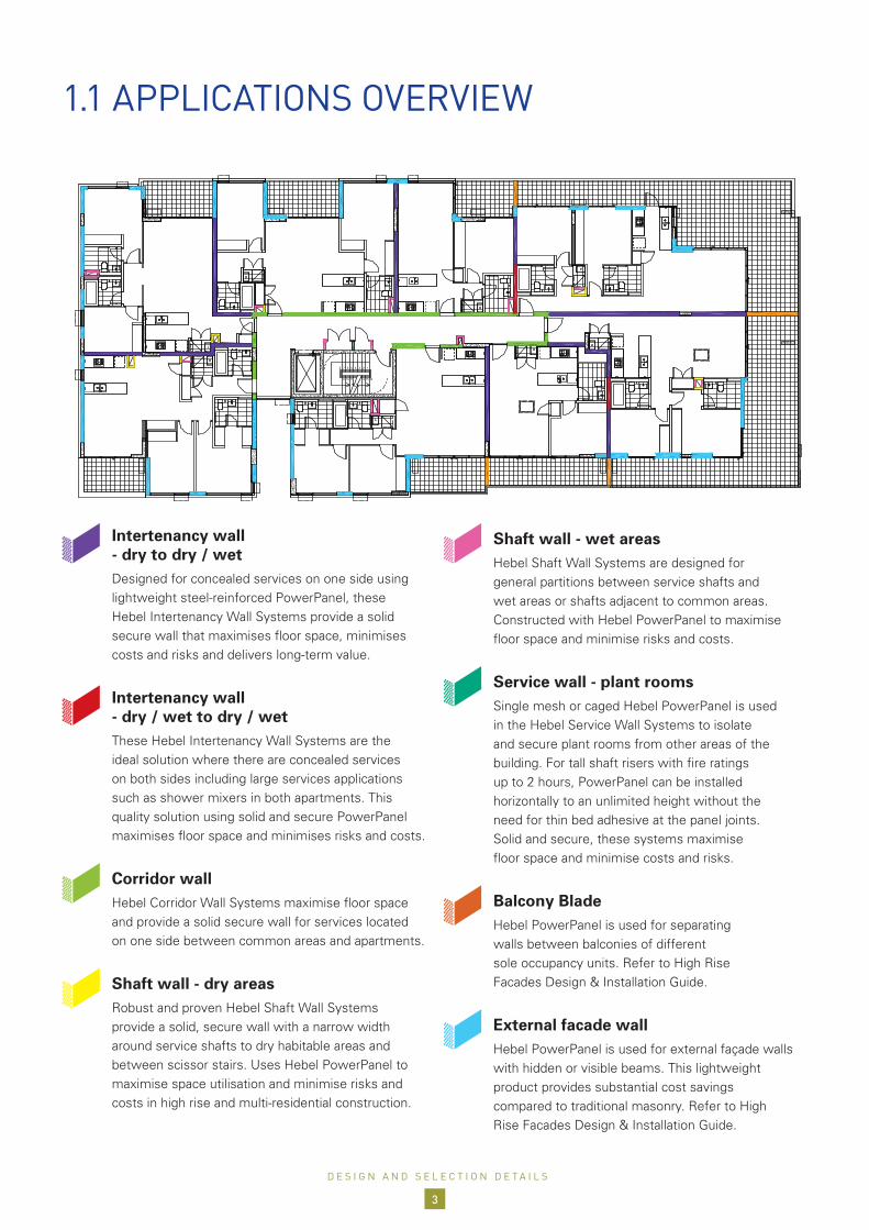
1.1 APPLICATIONS OVERVIEW
Intertenancy wall - dry to dry / wet
Designed for concealed services on one side using lightweight steel-reinforced PowerPanel, these Hebel Intertenancy Wall Systems provide a solid secure wall that maximises floor space, minimises costs and risks and delivers long-term value.
Intertenancy wall - dry / wet to dry / wet
These Hebel Intertenancy Wall Systems are the ideal solution where there are concealed services on both sides including large services applications such as shower mixers in both apartments. This quality solution using solid and secure PowerPanel maximises floor space and minimises risks and costs.
Corridor wall Hebel Corridor Wall Systems maximise floor space
and provide a solid secure wall for services located on one side between common areas and apartments.
Shaft wall - dry areas Robust and proven Hebel Shaft Wall Systems
provide a solid, secure wall with a narrow width around service shafts to dry habitable areas and between scissor stairs. Uses Hebel PowerPanel to maximise space utilisation and minimise risks and costs in high rise and multi-residential construction.
Shaft wall - wet areas Hebel Shaft Wall Systems are designed for
general partitions between service shafts and wet areas or shafts adjacent to common areas. Constructed with Hebel PowerPanel to maximise floor space and minimise risks and costs.
Service wall - plant rooms Single mesh or caged Hebel PowerPanel is used
in the Hebel Service Wall Systems to isolate and secure plant rooms from other areas of the building. For tall shaft risers with fire ratings up to 2 hours, PowerPanel can be installed horizontally to an unlimited height without the need for thin bed adhesive at the panel joints. Solid and secure, these systems maximise floor space and minimise costs and risks.
Balcony Blade Hebel PowerPanel is used for separating
walls between balconies of different sole occupancy units. Refer to High Rise Facades Design & Installation Guide.
External facade wall Hebel PowerPanel is used for external façade walls
with hidden or visible beams. This lightweight product provides substantial cost savings compared to traditional masonry. Refer to High Rise Facades Design & Installation Guide.
D E S I G N A N D S E L E C T I O N D E T A I L S
3

1.2 INTERTENANCY WALLconcealed water services one side
System Application FRL (A) Wall linings (D)
Cavity width (mm)
InsulationAcoustic
rating Rw+Ctr (C)
Wall width (mm)
Hebel1070 Dry to Dry-/90/90 for
wall heights up to 3.3m
Both Sides 13mm Gyprock CD
2075mm Bradford Acoustigard 11
50 185
Hebel1071 Dry to Wet Hebel Side – 13mm Gyprock CD Stud Side – 13mm Aquachek (B) 50 185
NOTES:(A) For wall heights higher than 3.3m, caged tongue & groove PowerPanel can be used and will achieve a FRL of -/120/120 for wall heights up to 4.65m (vertically).
Also see Construction details section.(B) 13mm Aquachek can be replaced by 9mm FC Sheeting and achieve the same Acoustic & Fire Rating Levels.(C) Rw+Ctr values are based on acoustic opinion 20140366.30/2702A/R0/GW provided by Acoustic Logic Consultancy Pty Ltd.(D) The minimum mass of plasterboard must be 8.5kg/m2.
GENERAL NOTES:1. Intertenancy wall systems Hebel1070 - 1071 meet NCC 2019 deemed-to-satisfy discontinuous construction requirements.2. Hebel1070 - 1071 are designed to resist a maximum ultimate lateral pressure of 0.50kPa. Contact Hebel Technical Services if lateral pressures exceed 0.50kPa.
Hebel PowerPanel (tongue & groove)
Slotted angle 75mm x 50mm x 1.2mm BMT
CSR FireSeal™ sealant and backing rod
Gyprock® plasterboard as per system requirements
Rondo steel stud framing system
Gyprock® plasterboard as per system requirements
Nº6 x 25mm type S needle point screws
14-10 x 65mm hex head type 17 screw
Nº10 x 50mm bugle head coarse thread screw
Slotted base angle 50mm x 50mm x 0.8mm BMT fixed to slab
Rondo track fixed to slab
Bradford insulation as per system requirements
Concrete soffit
Concrete slab
DRY/WETDRY
14-10 x 65mm hex head type 17 screw
Rondo P50 detail
CSR FireSeal™ sealant
Hebel Adhesive (gaps ≤ 3mm) or Hebel Mortar (gaps > 3mm)
D E S I G N A N D S E L E C T I O N D E T A I L S
4

1.2 INTERTENANCY WALLconcealed water services one side
1.3 INTERTENANCY WALLconcealed water services both sides
System Application FRL (A) Wall linings (D)Insulation
A
Cavity width (mm)
Insulation B
Acoustic rating
Rw+Ctr (C)
Wall width (mm)
Hebel1072 Dry to Dry-/90/90 for wall heights up to 3.3m
Both Sides 13mm Gyprock CD
50mm Bradford
Acoustigard 11
35
75mm Bradford
Acoustigard 11
50 243
Hebel1073 Dry to Wet Dry Side – 13mm Gyprock CD Wet Side – 13mm Aquachek (B)
20
50 228
Hebel1074 Wet to Wet Both Sides 13mm Aquachek (B) 50 228
NOTES:(A) For wall heights higher than 3.3m, caged tongue & groove PowerPanel can be used and will achieve a FRL of -/120/120 for wall heights up to 4.65m (vertically).
Also see Construction details section.(B) 13mm Aquachek can be replaced by 9mm FC Sheeting and achieve the same Acoustic & Fire Rating Levels.(C) Rw+Ctr values are based on acoustic opinion 20140366.30/2702A/R0/GW provided by Acoustic Logic Consultancy Pty Ltd.(D) The minimum mass of plasterboard must be 8.5kg/m2.
GENERAL NOTES:1. Intertenancy wall systems Hebel1072 - 1074 meet NCC 2019 deemed-to-satisfy discontinuous construction requirements.2. Hebel1072 - 1074 are designed to resist a maximum ultimate lateral pressure of 0.50kPa. Contact Hebel Technical Services if lateral pressures exceed 0.50kPa.
Hebel PowerPanel (tongue & groove)
Slotted angle 75mm x 50mm x 1.2mm BMT
Optional: track or angle powerfixed to soffit
CSR FireSeal™ sealant and backing rod
Gyprock® plasterboard as per system requirements
Rondo No129 furring channel (28mm) & BetaGrip clips as per system requirements
Nº6 x 25mm type S needle point screws
14-10 x 65mm hex head type 17 screw
CSR FireSeal™ sealant
Slotted base angle 50mm x 50mm x 0.8mm BMT fixed to slab
Rondo track fixed to slab
Rondo steel stud framing system
Bradford insulation as per system requirements
14-10 x 65mm hex head type 17 screw
Concrete soffit
Concrete slab
Rondo P50 detail
Hebel Adhesive (gaps ≤ 3mm) or Hebel Mortar (gaps > 3mm)
Optional: track or angle powerfixed to slab
DRY/WETDRY/WET
A B
D E S I G N A N D S E L E C T I O N D E T A I L S
5

CSR FireSeal™ sealant and backing rod
Deflection head to manufacturer’s specifications
Rondo steel stud framing system
Gyprock® plasterboard as per system requirements
Bradford insulation as per system requirements
14-10 x 65mm hex head type 17 screw
Slotted base angle 50mm x 50mm x 0.8mm BMT fixed to slab
Rondo track fixed to slab
Slotted angle 75mm x 50mm x 1.2mm BMT
Hebel PowerPanel (tongue & groove)
Concrete soffit
Concrete slab
14-10 x 65mm hex head type 17 screw
Rondo P50 detail
DRY/WET
DRY/WET
Nº6 x 25mm type S needle point screws
A B
System Application FRL (A) Wall linings (D)Insulation
A
Cavity width (mm)
Insulation B
Acoustic rating
Rw+Ctr (C)
Wall width (mm)
Hebel1075 Dry to Dry-/90/90 for wall heights up to 3.3m
Both Sides 13mm Gyprock CD
50mm Bradford
Acoustigard 11
20
75mm Bradford
Acoustigard 11
53 269
Hebel1076 Dry to Wet Dry Side – 13mm Gyprock CD Wet Side – 13mm Aquachek (B) 53 269
Hebel1077 Wet to Wet Both Sides 13mm Aquachek (B) 54 269
NOTES:(A) For wall heights higher than 3.3m, caged tongue & groove PowerPanel can be used and will achieve a FRL of -/120/120 for wall heights up to 4.65m (vertically). Also see
Construction details section.(B) 13mm Aquachek can be replaced by 9mm FC Sheeting and achieve the same Acoustic & Fire Rating Levels.(C) Rw+Ctr values are based on acoustic opinion 20140366.30/2702A/R0/GW provided by Acoustic Logic Consultancy Pty Ltd.(D) The minimum mass of plasterboard must be 8.5kg/m2.
GENERAL NOTES:1. Intertenancy wall systems Hebel1075 - 1077 meet NCC 2016 deemed-to-satisfy discontinuous construction requirements.2. Hebel1075 - 1077 are designed to resist a maximum ultimate lateral pressure of 0.50kPa. Contact Hebel Technical Services if lateral pressures exceed 0.50kPa.
1.4 INTERTENANCY WALLlarge concealed water services both sides
CSR FireSeal™ sealant
Hebel Adhesive (gaps ≤ 3mm) or Hebel Mortar (gaps > 3mm)
D E S I G N A N D S E L E C T I O N D E T A I L S
6

Hebel PowerPanel (tongue & groove)
Slotted angle 75mm x 50mm x 1.2mm BMTT
CSR FireSeal™ sealant and backing rod
Gyprock® plasterboard as per system requirements
14-10 x 65mm hex head type 17 screw
Rondo steel stud framing system
Gyprock® plasterboard as per system requirements
Nº6 x 25mm type S needle point screws
14-10 x 65mm hex head type 17 screw
Nº10 x 50mm bugle head coarse thread screw
Slotted base angle 50mm x 50mm x 0.8mm BMT fixed to slab
Rondo track fixed to slab
Bradford insulation as per system requirements
Rondo P50 detail
Concrete soffit
Concrete slab
APARTMENTCORRIDOR
System Application FRL (A) Wall linings (D)
Cavity width (mm)
InsulationAcoustic
rating Rw (C)
Wall width (mm)
Hebel1148 Dry to Dry -/90/90 for wall heights up to 3.3m
Both Sides 13mm Gyprock CD
1550mm Bradford Acoustigard 11
58 180
Hebel1149 Dry to Wet Corridor Side – 13mm Gyprock CD Stud Side – 13mm Aquachek (B) 59 180
NOTES: (A) For wall heights higher than 3.3m, caged tongue & groove PowerPanel can be used and will achieve a FRL of -/120/120 for wall heights up to 4.65m (vertically). Also see
Construction details section.(B) 13mm Aquachek can be replaced by 9mm FC Sheeting and achieve the same Acoustic & Fire Rating Levels.(C) Rw values are based on acoustic opinion 20140366.30/2702A/R0/GW provided by Acoustic Logic Consultancy Pty Ltd.(D) The minimum mass of plasterboard must be 8.5kg/m2.
GENERAL NOTES:1. Hebel1148 - 1149 are designed to resist a maximum ultimate lateral pressure of 0.50kPa. Contact Hebel Technical Services if lateral pressures exceed 0.50kPa.
1.4 INTERTENANCY WALLlarge concealed water services both sides
1.5 CORRIDOR WALLconcealed water services one side
CSR FireSeal™ sealant
Hebel Adhesive (gaps ≤ 3mm) or Hebel Mortar (gaps > 3mm)
D E S I G N A N D S E L E C T I O N D E T A I L S
7

Hebel PowerPanel (tongue & groove)
Slotted angle 75mm x 50mm x 1.2mm BMT
14-10 x 65mm hex head type 17 screw
Rondo No129 furring channel (28mm) and BetaGrip clips as per system requirements
Gyprock® plasterboard as per system requirements
Bradford insulation as per system requirements
14-10 x 65mm hex head type 17 screw
N°10 x 50mm bugle head coarse thread screw
Nº6 x 25mm type S needle point screws
Slotted base angle 50mm x 50mm x 0.8mm BMT fixed to slab
Concrete soffit
Concrete slab
APARTMENTCORRIDOR
Rondo P50 detail
CSR FireSeal™ sealant and backing rod
System Application FRL (A) Wall linings (D)
Cavity width (mm)
InsulationAcoustic
rating Rw(C)
Wall width (mm)
Hebel1150 Dry to Dry -/90/90 for wall heights up to 3.3m
Both Sides 13mm Gyprock CD
4350mm Bradford Acoustigard 11
52 144
Hebel1151 Dry to Wet Corridor Side – 13mm Gyprock CD Stud Side – 13mm Aquachek (B) 53 144
NOTES:(A) For wall heights higher than 3.3m, caged tongue & groove PowerPanel can be used and will achieve a FRL of -/120/120 for wall heights up to 4.65m (vertically). Also see
Construction details section.(B) 13mm Aquachek can be replaced by 9mm FC Sheeting and achieve the same Acoustic & Fire Rating Levels.(C) Rw values are based on acoustic opinion 20140366.30/2702A/R0/GW provided by Acoustic Logic Consultancy Pty Ltd.(D) The minimum mass of plasterboard must be 8.5kg/m2.
GENERAL NOTES:1. Hebel1150 - 1151 are designed to resist a maximum ultimate lateral pressure of 0.50kPa. Contact Hebel Technical Services if lateral pressures exceed 0.50kPa.
1.6 CORRIDOR WALLconcealed water services one side with furring channel
CSR FireSeal™ sealant
Hebel Adhesive (gaps ≤ 3mm) or Hebel Mortar (gaps > 3mm)
D E S I G N A N D S E L E C T I O N D E T A I L S
8

System Application FRL (A),(B) Wall linings (E)
Acoustic rating
Rw+Ctr (D)
Wall width (mm)
Hebel1163 Shaft to Wet -/90/90 for wall heights up to
3.3m
13mm Aquachek (C) 34 88
Hebel1164 Shaft to Common 13mm Gyprock CD 33 88
Hebel1165 Shaft to Wet -/120/120 for wall heights up to
3.3m
13mm Fyrchek MR 34 88
Hebel1166 Shaft to Common 13mm Fyrechek 34 88
NOTES:(A) To achieve an FRL of -/120/120 for wall heights up to 3.3m use 13mm Fyrchek, or Fyrchek MR plasterboard direct fixed to the Hebel panels and extended to the concrete soffit as
shown. CSR FireSeal sealant joints required to all perimeters of the plasterboard . (B) For wall heights higher than 3.3m, caged tongue & groove PowerPanel can be used and will achieve a FRL of -/120/120 for wall heights up to 4.65m (vertically).
Also see Construction details section.(C) 13mm Aquachek can be replaced by 9mm FC Sheeting and achieve the same Acoustic & Fire Rating Levels.(D) Rw+Ctr values are based on acoustic opinion 20140366.30/2702A/R0/GW provided by Acoustic Logic Consultancy Pty Ltd.(E) The minimum mass of plasterboard must be 8.5kg/m2.GENERAL NOTES:1. Hebel1163 - 1166 are designed to resist a maximum ultimate lateral pressure of 0.50kPa. Contact Hebel Technical Services if lateral pressures exceed 0.50kPa.
Hebel PowerPanel (tongue & groove)
CSR FireSeal™ sealant and backing rod
Slotted angle 75mm x 50mm x 1.2mm BMT
Extended 13mm Fyrchek MR / Fyrchek plasterboard and CSR FireSeal sealant for FRL -/120/120 applications (Hebel1165 - Hebel1166)
14-10 x 65mm hex head type 17 screw
Nº10 x 50mm bugle head coarse thread screw
14-10 x 100mm MP bugle head screw
CSR FireSeal™ sealant
Slotted base angle 50mm x 50mm x 0.8mm BMT fixed to slab
Hebel Adhesive (gaps ≤ 3mm) or Hebel Mortar (gaps > 3mm)
Gyprock® plasterboard as per system requirements
Concrete soffit
Concrete slab
WET / COMMONSHAFT
Rondo P50 detail
1.6 CORRIDOR WALLconcealed water services one side with furring channel
1.7 SHAFT WALLadjacent to wet or common areas
D E S I G N A N D S E L E C T I O N D E T A I L S
9

System Application FRL (A) Wall linings (D)
Cavity width (mm)
InsulationAcoustic
rating Rw+Ctr (C)
Wall width (mm)
Hebel1160 Shaft to Dry -/90/90 for wall
heights up to 3.3m
13mm Gyprock CD 4350mm Bradford Acoustigard 11 40 131
Hebel1162 Shaft to Wet 13mm Aquachek (B) 28 NIL 37 116
NOTES:(A) For wall heights higher than 3.3m, caged tongue & groove PowerPanel can be used and will achieve a FRL of -/120/120 for wall heights up to 4.65m (vertically). Also see
Construction details section.(B) 13mm Aquachek can be replaced by 9mm FC Sheeting and achieve the same Acoustic & Fire Rating Levels.(C) Rw+Ctr values are based on acoustic opinion 20140366.30/2702A/R0/GW provided by Acoustic Logic Consultancy Pty Ltd.(D) The minimum mass of plasterboard must be 8.5kg/m2.
GENERAL NOTES:1. Hebel1160 & 1162 are designed to resist a maximum ultimate lateral pressure of 0.50kPa. Contact Hebel Technical Services if lateral pressures exceed 0.50kPa.
Hebel PowerPanel (tongue & groove)
Slotted angle 75mm x 50mm x 1.2mm BMT
Optional: track or angle fixed to soffit
Rondo No129 furring channel (28mm) and BetaGrip clips as per system requirements
Gyprock® plasterboard as per system requirements
Nº6 x 25mm type S needle point screws
CSR FireSeal™ sealant
14-10 x 65mm hex head type 17 screw
Slotted base angle 50mm x 50mm x 0.8mm BMT fixed to slab
Gyprock® plasterboard as per system requirements
Concrete soffit
Concrete slab
14-10 x 65mm hex head type 17 screw
Rondo P50 detail
SHAFT DRY
CSR FireSeal™ sealant and backing rod
1.8 SHAFT WALLadjacent to dry habitable rooms
Bradford insulation as per system requirements
Hebel Adhesive (gaps ≤ 3mm) or Hebel Mortar (gaps > 3mm)
D E S I G N A N D S E L E C T I O N D E T A I L S
10

Code Application FRL (A) Wall linings Hebel componentAcoustic
rating Rw (B)
Wall width (mm)
Paint finish
Hebel1169 Bare Shaft -/90/90 for wall heights up to 3.3m Nil 75mm PowerPanel T&G 33 75 Optional
NOTES:(A) Also see Construction details section.(B) Rw values are based on acoustic test 2010861.3/1506A.
GENERAL NOTES:1. Hebel1169 is designed to resist a maximum ultimate lateral pressure of 0.50kPa. Contact Hebel Technical Services if lateral pressures exceed 0.50kPa.
Hebel PowerPanel (tongue & groove)
Fix angle to slab as per project specifications
Fix angle to slab as per project specifications
Hebel Adhesive (gaps ≤ 3mm) or Hebel Mortar (gaps > 3mm)
Slotted angle 75mm x 50mm x 1.2mm BMT
Concrete slab
Concrete slab
CSR FireSeal™ sealant and backing rod
Slotted base angle 50 x 50 x 0.8mm for H 3300mm or slotted angle 75 x 50 x 1.2mm for H>3300mm
14-10 x 65mm hex head type 17 screw (located centrally on each panel)*
14-10 x 65mm hex head type 17 screw (located centrally on each panel)*
SHAFT
1.8 SHAFT WALLadjacent to dry habitable rooms
1.9 SERVICES WALLfor walls up 3.3 metres high
D E S I G N A N D S E L E C T I O N D E T A I L S
11

Code Application FRL (A) Wall linings Hebel componentAcoustic
rating Rw (B)
Wall width (mm)
Paint finish
Hebel1159 Bare Shaft-/120/120 for wall
heights up to 4.65m
Nil 75mm caged T&G PowerPanel 33 75 Optional
NOTES:(A) Also see Construction details section.(B ) Rw values are based on acoustic opinion 2010861.3/1506A/R0/GW provided by Acoustic Logic Consultancy Pty Ltd.
GENERAL NOTES:1. Hebel1159 is designed to resist a maximum ultimate lateral pressure of 0.50kPa. Contact Hebel Technical Services if lateral pressures exceed 0.50kPa.
Hebel PowerPanel (caged tongue &
groove)
Fix angle to slab as per project specifications
Fix angle to slab as per project specifications
Hebel Mortar
Slotted angle 75mm x 50mm x 1.2mm BMT
Concrete slab
Concrete slab
CSR FireSeal™ sealant and backing rod
Slotted base angle 50 x 50 x 0.8mm for H 3300mm or Slotted angle 75 x 50 x 1.2mm for H>3300mm
14-10 x 65mm hex head type 17 screw (located centrally on each panel)*
14-10 x 65mm hex head type 17 screw (located centrally on each panel)*
SHAFT
1.10 SERVICES WALLfor walls with 2 hour fire rating up to 4.65 metres high
D E S I G N A N D S E L E C T I O N D E T A I L S
12
1.10 SERVICES WALLfor walls with 2 hour fire rating up to 4.65 metres high
1.11 SYSTEM COMPONENTS
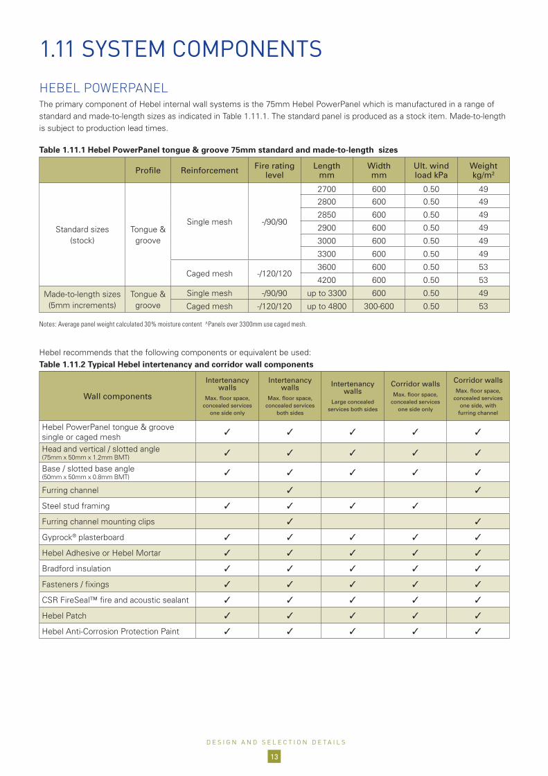
HEBEL POWERPANELThe primary component of Hebel internal wall systems is the 75mm Hebel PowerPanel which is manufactured in a range of standard and made-to-length sizes as indicated in Table 1.11.1. The standard panel is produced as a stock item. Made-to-length is subject to production lead times.
Table 1.11.1 Hebel PowerPanel tongue & groove 75mm standard and made-to-length sizes
Profile Reinforcement Fire rating level
Length mm
Width mm
Ult. wind load kPa
Weight kg/m2
Standard sizes (stock)
Tongue & groove
Single mesh -/90/90
2700 600 0.50 492800 600 0.50 49
2850 600 0.50 49
2900 600 0.50 49
3000 600 0.50 49
3300 600 0.50 49
Caged mesh -/120/1203600 600 0.50 53
4200 600 0.50 53
Made-to-length sizes (5mm increments)
Tongue & groove
Single mesh -/90/90 up to 3300 600 0.50 49
Caged mesh -/120/120 up to 4800 300-600 0.50 53
Notes: Average panel weight calculated 30% moisture content ^Panels over 3300mm use caged mesh.
Hebel recommends that the following components or equivalent be used: Table 1.11.2 Typical Hebel intertenancy and corridor wall components
Wall components
Intertenancy walls
Max. floor space, concealed services
one side only
Intertenancy walls
Max. floor space, concealed services
both sides
Intertenancy walls
Large concealed services both sides
Corridor wallsMax. floor space,
concealed services one side only
Corridor wallsMax. floor space,
concealed services one side, with
furring channel
Hebel PowerPanel tongue & groove single or caged mesh
3 3 3 3 3
Head and vertical / slotted angle (75mm x 50mm x 1.2mm BMT)
3 3 3 3 3
Base / slotted base angle (50mm x 50mm x 0.8mm BMT)
3 3 3 3 3
Furring channel 3 3
Steel stud framing 3 3 3 3
Furring channel mounting clips 3 3
Gyprock® plasterboard 3 3 3 3 3
Hebel Adhesive or Hebel Mortar 3 3 3 3 3
Bradford insulation 3 3 3 3 3
Fasteners / fixings 3 3 3 3 3
CSR FireSeal™ fire and acoustic sealant 3 3 3 3 3
Hebel Patch 3 3 3 3 3
Hebel Anti-Corrosion Protection Paint 3 3 3 3 3
D E S I G N A N D S E L E C T I O N D E T A I L S
13

Figure 1.2.1 Hebel PowerPanel single and caged tongue & groove cross-sections
Table 1.2.3 Typical Hebel shaft and service wall components
Wall components
Shaft wallsGeneral partitions on service shaft to wet areas or shafts
adjacent to common areas
Shaft wallsMax. floor space with concealed
services one side
Services wallSeparating walls to isolate and secure plants from other areas. FRL -/90/90
up to 3.3m
Services wallSeparating walls to isolate and secure plants from other
areas. FRL -/120/120 up to 4.65m
Horizontal
Shaft wall
Hebel PowerPanel tongue & groove single or caged mesh 3 3 3 3 3
Head and vertical/ slotted angle (75mm x 50mm x 1.2mm BMT)
3 3 3 3 3
Base / slotted base angle (50 x 50 x 0.8mm for H 3300mm) (75 x 50 x 1.2mm for H>3300mm)
3 3 375 x 50 x
1.2mm only75 x 50 x
1.2mm only
Furring channel 3 Optional Optional
Furring channel mounting clips 3 Optional Optional
Gyprock® plasterboard 3 3 Optional Optional
Hebel Adhesive 3 3 3 3 3
Hebel Mortar 3 3 3
Hebel Patch 3 3 3 3 3
Bradford insulation 3
Fasteners / fixings 3 3 3 3 3
CSR FireSeal™ fire and acoustic sealant 3 3 3 3 3
Hebel Anti-Corrosion Protection Paint 3 3 3 3 3
Note: CSR has engineered and tested the PowerPanel system to comply with the National Construction Code (NCC) and relevant Australian Standards. It cannot guarantee products and accessories not specified and sold by CSR will perform to these standards.The Product Guarantee will only apply if all components used in the system are specified and sold by CSR or its agents
75mm
600mm
T&G ProfileStandard (Nil) Profile
75mm
600mm
75mm
600mm
T&G ProfileStandard (Nil) Profile
75mm
600mm
75mm
600mm
T&G ProfileStandard (Nil) Profile
75mm
600mm
75mm
600mm
Caged Mesh (panels longer than 3300mm)Standard (Nil) Profile
75mm
600mmSingle mesh tongue & groove - 600mm wide Caged mesh tongue & groove – 300 to 600mm wide
(for panels > 3.3m or for FRL -/120/120)
SLOTTED ANGLE CONNECTIONSFor positioning and restraining (with added screw fixings) the top and bottom of the panels. See Table 1.2.2 for typical intertenancy and corridor walls. See Table 1.2.3 for typical shaft and services walls.
Slotted galvanised steel angle for head, vertical and base connections for H > 3300mm and/ or for 2 hour rated systems. 75 x 50 x 1.2mm BMT. Minimum slot height 20mm.
Slotted galvanised steel angle for base connection for H 3300mm. 50 x 50 x 0.8mm BMT
All angles with BMT greater than 0.8mm will have to be slotted to allow penetration of fixings. Head connections require slotted angle to allow for deflection of slab above.
HEBEL ADHESIVEHebel Adhesive (supplied in 20kg bag) is used for bonding the panels together at vertical and horizontal joints or for gaps at base ≤ 3mm.
D E S I G N A N D S E L E C T I O N D E T A I L S
14

HEBEL MORTARHebel Mortar (supplied in 20kg bag) is used to provide a level base for panel installation as well as providing acoustic and fire protection at the base of the panels.
HEBEL PATCHMinor chips or damage to panels are repaired using Hebel Patch (supplied in 10kg bag).
CSR FIRESEALTo attain the specified FRL and/or Rw requirements, all perimeter gaps and penetrations must be carefully tooled and completely filled with CSR FireSeal installed to the manufacturer’s specifications.
BACKING RODCSR Hebel recommends the use of an open cell polyurethane backing rod which ensures the correct depth of sealant is achieved. The backing rod provides a firm backing against which sealant can be tooled, and allows the sealant to bond on both sides of the joint to the Hebel substrate. The open cell backing facilitates faster curing time and is much more compressible, allowing use in a wider range of joints.
HEBEL ANTI-CORROSION PROTECTION PAINTReinforcement exposed when panels are cut must be coated with a liberal application of Hebel Anti-Corrosion Protection Paint.
FURRING CHANNEL MOUNTING CLIPSClips are proprietary components enabling the mounting of furring channel and plasterboard onto Hebel PowerPanel. This provides a cavity space which can change the acoustic insulation performance of the wall system. Clips used on Hebel intertenancy and corridor walls are:
BetaGrip1 (BG01) clip
STEEL STUD FRAMEWORKZinc coated steel studs, noggings, head and base tracks are used to create separated stud framework, which in conjunction with the Hebel PowerPanel, provides an asymmetric cavity wall assembly.
There are a number of different steel stud framework component manufacturers. All steel stud framework components are to be designed in accordance with manufacturer’s specifications, and AS/NZS 4600.
FURRING CHANNELRondo galvanised steel furring channels are mounted onto the BetaGrip clips. Furring channel used:
Rondo Nº129, 28 x 38 x 0.50mm, BMT channels
BRADFORD GLASSWOOLManufactured in Australia Bradford Glasswool boards and blankets provide excellent fire resistance and acoustic performance properties for intertenancy, corridor and shaft walls. Bradford Glasswool products are manufactured by spinning molten glass, containing up to 65% recycled content, into fine wool like fibres. These are bonded together using a thermosetting resin and employ safe to handle FBS-1 biosoluble Glasswool formulation. Products meet AS/NZS4859 requirements to ensure performance for the life of the building.
BRADFORD FIRESEAL™The Bradford Fireseal range provides rockwool fire protection insulation products designed to meet the NCC fire requirements for intertenancy walls and is typically used in junctions of intertenancy and external brick walls.This range is made from biosoluble rockwool, an insulation material specially formulated to provide fire protection. It is manufactured by spinning a molten mixture of natural rock and recycled blast furnace waste products into fibres which are bonded with a thermosetting resin.
D E S I G N A N D S E L E C T I O N D E T A I L S
15

GYPROCK® PLASTERBOARDHebel intertenancy and corridor walls incorporate Gyprock® plasterboard on both sides. The type, thickness and densities of plasterboard will be as per the specified wall requirements. The minimum mass of plasterboard must be 8.5kg/m2.
Additional information is available from CSR Gyprock.
FIXINGSMost screw fixings are timber type, which is sufficient for penetrating the metal thicknesses outlined in this Design Guide. Connections that have larger metal thicknesses may require a metal type screw and will need to be designed and approved by the project engineer.
Slotted head / base angles to concrete fixings
The fixing to secure the tracks to the concrete slab and soffits shall be capable of withstanding a shear load of 0.75kN per metre (for wall heights up to 3.0 metres). For high wind pressures the designer shall determine if mechanical fasteners are required. The following minimum fixings shall be provided:
Drive pins and concrete nails (check size and suitability for fire rated situations with the manufacturer).
6mm diameter mechanical fasteners.
PowerPanel to slotted head and base angle fixings
Use 14-10 x 65mm hex head type 17 screw or equivalent, when fixing through the angle into the panel. Angles with BMT greater than 0.8mm will have to be slotted.
Use 14-10 x 150mm hex head type 17 screw or equivalent, when fixing into panel at corner or T-junction.
Use 14-10 x 100mm MP bugle head screw or equivalent, when fixing through panel and into angle. For angles with BMT greater than 0.8mm, screw will require the appropriate tip.
Gyprock® plasterboard to PowerPanel fixing
Nº10 x 50mm bugle head coarse thread screw or equivalent.
Furring channel mounting clip to PowerPanel fixing
12-11 x 65mm hex head screw type 17.
Gyprock® plasterboard to furring channel / metal stud fixing
Nº6 x 25mm type S needlepoint screw or equivalent.
Door frames to PowerPanel fixings
Nº8 x 50mm coarse thread screw or equivalent. Check screw requirements with door manufacturer’s specifications.
D E S I G N A N D S E L E C T I O N D E T A I L S
16

2.1 ACOUSTIC PERFORMANCE
NCC COMPLIANT HEBEL INTERNAL WALL SYSTEMSThe wall systems outlined have been assessed to comply with the NCC requirement for intertenancy, corridor, shaft and service walls. This table must be read in conjunction with all information provided in this Design and Installation Guide, and acoustic opinions 20140366.30/2702A/R0/GW and 2010861.3/1506A/R0/GW provided by Acoustic Logic Consultancy Pty Ltd and acoustic test ATF-676. Selection of Hebel internal wall systems shown in the table should be taken with specialist consultant’s advice. For walls requiring discontinuous construction, the gap/cavity must be 20mm minimum.
IMPACT SOUND PERFORMANCEAll Hebel intertenancy and corridor walls are cavity wall systems without connections between the separate wall leaves. Therefore, no mechanical path exists for the transmission of impact sound. Provided a 20mm gap is maintained between the separated wall leaves, all intertenancy and corridor walls can meet the ‘discontinuous construction’ requirement of the NCC.
ACOUSTIC PERFORMANCE DESIGN RECOMMENDATIONS1. Hebel recommends engaging a specialist acoustic
consultant on a project-by-project basis to provide design advice, confirmation of anticipated field performance, detailing and installation inspections.
2. When selecting the appropriate Hebel wall, the designer or specifier must be aware that the laboratory Rw values are almost always higher than the field measured values. Therefore, allowances should be made for the lower expected field values during the selection of the system.
3. Separate advice from a specialist acoustic consultant should be sought to determine the effect on acoustic performance due to any changes to the Hebel wall systems, and any required modification of the installation details pertaining to the systems.
4. Increasing of cavity widths, using higher density or thicker insulation or plasterboard, will generally maintain or increase the acoustic performance of the Hebel wall.
5. The acoustic performance values of the Hebel walls shown in the systems pages are a guide only as to
expected lab test performance. They do not constitute a field performance guarantee as factors such as the presence of flanking paths, quality of installation of the system, onsite detailing of junctions, room shapes and size, etc can significantly affect field performance. Maximising the field performance depends on the following factors:
systems are installed in accordance with the manufacturer’s standard installation details.
good quality installation practices including the sealing of all junctions and joints and maintaining specified clearances.
systems are installed with all junctions acoustically sealed so that negligible sound transmission occurs at these points.
all services penetrations, etc are acoustically sealed and treated so that negligible sound transmission occurs through these points.
flanking paths are eliminated and the structures into which the systems are installed are capable of allowing the nominated rating to be achieved
site testing conditions.
S Y S T E M P E R F O R M A N C E
17

2.2 FIRE RATING PERFORMANCE
FIRE RESISTANCE LEVEL (FRL) RATINGSThe maximum wall heights in the systems described in this Design and Installation Guide are taken from CSIRO Fire Test Report FSV-0979 and Exova Warringtonfire Assessment Report 26095-13. These values are only applicable to the Hebel walls outlined in this Design and Installation Guide.
The fire performance for the various junctions of these wall systems (head details at concrete soffit, wall base details, control joint details including junctions with concrete walls and columns and a suite of service penetrations details) using CSR FireSeal sealant are covered in Exova Warringtonfire Assessment Report 27915-13.
The FRL rating of the wall can be affected by the penetrations and the method adopted to protect these penetrations. A fire collar with a -/60/60 FRL rating will govern the FRL of the wall, even if the wall configuration has a FRL rating of -/90/90.
FIRE PROTECTION OF PENETRATIONSPenetrations through a Hebel wall to accommodate pipework, electrical cabling or ductwork will have to be protected (fire stop), to prevent the spread of fire through the penetration.
CSR Hebel provides a fire-rated sealant, CSR FireSeal and recommends contacting a reputable manufacturer of fire protection systems for other appropriate products such as fire collars.
S Y S T E M P E R F O R M A N C E
18

2.3 STRUCTURAL PERFORMANCE
STRUCTURAL PERFORMANCEHebel internal wall systems are non-loadbearing walls used in internal applications. The walls are designed to resist a maximum ultimate lateral pressure of 0.50kPa, and a deflection limit of H/240 (Height ÷ 240) or 20mm maximum.
Table 2.3.1 Recommended minimum gap between the stud frame and PowerPanel
Wall height (mm)
H/240 (mm)
Minimum gap (mm)
2400 10 12
2550 11 13
2700 12 14
2850 12 14
3000 13 15
3200 14 16
3550 15 17
3900 17 19
4200 18 20
CUTTING OF HEBEL POWERPANELFor the load parameters outlined above (UDL 0.50kPa/ultimate), the standard Hebel PowerPanels can be reduced in length by cutting 150mm maximum from each end, and to a minimum width of 270mm. For UDL loads greater than 0.50kPa (ultimate), custom Hebel PowerPanel will have to be designed to ensure structural adequacy when cut.
STEEL STUD FRAMEThe steel framing presented in this Design and Installation Guide for various wall systems has not been approved for the design parameters in this Design and Installation Guide. It is the designer’s responsibility to determine an appropriate steel framing system. Several items the designer must allow for are: lateral loadings, wall height, deflection limits, offset distance (gap) from the panel, building movement and control joint locations.
As a minimum the wall will have a deflection limit of H/240. As a guide, Hebel recommends providing a minimum gap distance of Height/240 + installation tolerance. For example, H = 2400mm and installation tolerance = 2mm, then minimum gap = 2400/240+2 = 12mm. This is to ensure that the two leaves of the cavity wall do not touch during service loading. Table 2.3.1 outlines the recommended minimum gap to suit a range of wall heights for the H/240 deflection limit. For walls requiring discontinuous construction a minimum gap of 20mm must be specified to meet the NCC requirements.
CUSTOM HEBEL POWERPANELFor walls heights exceeding 3300mm or design parameters outside the scope of this guide, the panels will be custom Hebel PowerPanels. These panels are designed to satisfy the project’s individual design parameters, such as internal lateral (wind) pressure and onsite cutting requirements. Custom panels are subject to manufacturing lead times.
EARTHQUAKE LOADINGEarthquake loading has not been considered in this Design and Installation Guide.
S Y S T E M P E R F O R M A N C E
19

3.1 INSTALLATION FLOWCHARTS
Figure 3.1.1 Intertenancy, corridor and shaft wall systems with linings - Vertical installation
Wall Leaf
STEP 1: Install services as required
STEP 4: Install control joint backing rod
and sealants
STEP 2: Measure slab to soffit. If required cut panels
STEP 1: Install head and base angles
STEP 2: Install insulation as required
STEP 3: Install plasterboard
STEP 3: Apply Hebel Adhesive
or Hebel Mortar at base.See Construction details for
typical base details.
START
Hebel Wall Frames Linings
FINISH
STEP 4: Install Hebel PowerPanel
Wall framesOne side or
two sides
FinishingAll intertenacy and corridor
walls
STEP 1: Install steel stud framing as per manufacturer’s
recommendations
Furring channelsOne side or
two sides
STEP 1: Install furring channel clips and furring channel
as per manufacturer’s recommendations
STEP 6: Apply Hebel Patchin areas as required
STEP 8: For FRL -/120/120 fix final head angle
STEP 5: At panel joints apply Hebel Adhesive
STEP 7: Install backing rod and apply CSR FireSeal
at angle as required
Repeat Steps 4 & 5 until wall leaf complete
Clean up work area and set out wall positions
including steel stud wall frame position and door /
nib locations.
I N S T A L L A T I O N D E T A I L
20
HEBEL WALL LEAF SHOULD BE INSTALLED BEFORE SERVICES

Figure 3.1.2 Shaft and services wall systems - vertical and horizontal installation
STEP 1: Install first four (supporting) angle brackets
around perimeter
STEP 3: Apply Hebel Mortar (and packers if
required) at base
STEP 5: At panel joints apply Hebel Adhesive
Repeat steps 4 & 5 until wall completed
STEP 6: Apply Hebel Patch in areas as required
STEP 7: Apply backing rod and CSR FireSeal around
perimeter as required
STEP 8: For FRL -/120/120 fit final angle on vertical
edges for horizontal panels. Fit final angle at top of wall
for vertical panels.
STEP 2: Measure slab to soffit. If required, cut panels.
STEP 4: Install Hebel PowerPanel and fix to
(supporting) angle brackets
FINISH
Hebel
START
Clean up work area and set out wall positions
I N S T A L L A T I O N D E T A I L
21
HEBEL WALL LEAF SHOULD BE INSTALLED BEFORE SERVICES

SETTING OUT AND POSITIONING OF WALLSBefore commencing any installation work, clean and tidy up the work area. Mark out the location of the walls and door nibs, etc.
SLOTTED HEAD AND BASE ANGLE INSTALLATIONWhen the wall locations have been set out, fix the slotted angles and base angles to the concrete support structures. This is done using suitable fixings (see System components section) at 600mm maximum centres and maximum 100mm from ends. Seal all butt joints in head angle with CSR FireSeal.
HEBEL POWERPANEL INSTALLATIONThe panels can be cut onsite using a circular saw equipped with diamond tipped turbo cutting blade (for panel cutting limitations (see Structural performance section). All the loose AAC particles should be brushed off the panel with a stiff broom. Steel reinforcement that is exposed during cutting must be coated with a liberal application of Anti-Corrosion Protection Paint (see System components section). Any minor damage and chips to the panels must be repaired using Hebel Mortar.
Apply Hebel Adhesive or Hebel Mortar to base before installing panel. For gaps up to 3mm use Hebel Adhesive. For gaps over 3mm pack up with Hebel Mortar (maximum 15mm).
Fix the panel to the head and base angle with a minimum of two screws (see System components section), 50mm minimum from each end of the panel.
For following panels, apply thin bed adhesive to the entire vertical edge and install the next panel. Repeat the installation process until the wall is complete.
HEBEL ADHESIVE APPLICATIONHebel Adhesive is applied to the panel with a trowel.
When the panels are pushed together the joints are to be 2-3mm thick. Sufficient pressure must be applied to the panels when gluing to ensure the adhesive is fully bedded across the joint. Scrape off any excess adhesive protruding from the joints and fill any gaps.
Adhesive is to be mixed to the proportions and consistency as per the instructions on the bag.
BACKING ROD AND CSR FIRESEAL APPLICATIONThe backing rod should be installed to the manufacturer’s specifications.
CSR FireSeal should be applied with a minimum 10mm depth in all applications. Maximum widths are shown in the Construction details section of this Design and Installation Guide. For details not shown please contact CSR Hebel.
FURRING CHANNEL CLIP INSTALLATIONThe installation of the clips is typically at a maximum 600mm horizontal spacing and 1200mm vertical spacings. See System components section for appropriate fixings.
FURRING CHANNEL INSTALLATION Furring channels are fitted in floor / soffit tracks and clips on the wall. Furring channels should also be installed so they extend to the floor. For further information refer to manufacturer’s literature.
STEEL STUD FRAMEWORK INSTALLATION All steel stud frameworks are to be installed to the manufacturer’s specifications.
INSTALLATION OF BRADFORD INSULATION Installation of insulation should be completed in accordance with manufacturer’s handling and installation guidelines. The thickness of insulation provided should fully fill the cavity between studs or furring channels.
Insulation must be installed from concrete slab to concrete soffit. If there is any gap in the insulation the acoustic performance of the system may be adversely affected.
3.2 INSTALLATION
I N S T A L L A T I O N D E T A I L
22
HEBEL WALL LEAF SHOULD BE INSTALLED BEFORE SERVICES

GYPROCK® PLASTERBOARD Plasterboard sheets must be cut to fit neatly and should not be forced into position. The plasterboard is to extend to at least the ceiling level.
In Hebel intertenancy and corridor walls plasterboard is fixed directly to Hebel PowerPanel, steel furring channel or stud framework:
Direct fix to Hebel: plasterboard is to be installed in accordance with the Gyprock® plasterboard installation guidelines. Appropriate screws must be used to secure in position (see System components section).
Fit to furring channel or stud frame: plasterboard is to be installed in accordance with the Gyprock® Steel FrameWall Systems Installation Guide, NºGYP544.
The minimum mass of plasterboard must be 8.5kg/m2.
Handling and installation guidelines and additional information is available through CSR Gyprock.
Note: plasterboard must be screw-fixed only as gluing of sheets can adversely affect acoustic rating of system.
INSTALLATION OF FINAL SEALANTS All movement joints and other gaps should be sealed off and finished neatly with CSR FireSeal. Installation of CSR FireSeal must be carried out in accordance with the manufacturer’s specifications.
INSTALLATION OF PENETRATIONS: ELECTRICAL, PLUMBING AND OTHER SERVICES Installation of services and penetrations into Hebel internal wall systems should be carried out in an appropriate construction sequence. This will allow easy access to cavities, steel framed elements and Hebel panels, where services can be easily installed and neatly hidden. Hebel recommends installing the plumbing and cabling after the panels have been installed. The builder or project manager should confirm appropriate construction sequence for services and penetrations on a project by project basis.
Neat finishes for all penetrations are necessary to maintain the acoustic and fire integrity of the wall. See Construction details section in this Design and Installation Guide.
Hebel internal wall systems can accommodate penetrations without a reduction in structural performance where no more than one third the panel width is cut out of any one panel (maximum 200mm for a 600mm wide Hebel PowerPanel). The edge of the penetration should be a 15mm maximum from the service passing through the wall.
Contact your fire and acoustic consultants for detailing of penetrations to ensure the nominated fire and/or acoustic performance is achieved.
INSTALLATION OF FASTENERS AND FIXINGS All fixings and fasteners should be installed in accordance with the manufacturer’s specifications.
The correct sized fasteners for the construction of the wall system must always be used. Refer to the System components section for these fasteners. When fitting large or heavy fixtures, guidance on the correct fasteners can be found in the Hebel Technical Manual and / or fastener manufacturer’s recommendations.
I N S T A L L A T I O N D E T A I L
23
HEBEL WALL LEAF SHOULD BE INSTALLED BEFORE SERVICES

ACOUSTIC AND FIRE INTEGRITYPenetrations in walls for electrical fittings, telecommunications, large ductwork or plumbing systems can be a substantial source of sound leakage, which can affect the acoustic and fire performance of the wall.
When electrical, telecommunication or plumbing services are required, the contractor should install these services neatly and, when passing through the wall, should provide a close fitting hole, sealed with CSR FireSeal. Details of fire stopping products not covered within this Design & Installation Guide are to be specified by an appropriate consultant and installed in accordance with the manufacturer’s recommendations.
To prevent noise from water pipes degrading the acoustic amenity of the wall system, these pipes should be acoustically wrapped and resiliently fastened.
Where acoustic integrity is important, electrical switches must not be installed back-to-back as this could be a source of sound leakage. Refer Figure 3.3.1 (below) for switch box layout guidance.
Note: wall chasing is not permitted in accordance with the NCC (Volume 1 Specification F5.2).
CONTROL JOINTSControl joints must be provided at a maximum of 6m spacing. Recommended control joint widths should be 10mm minimum between PowerPanel and other building component. Control joints must also be provided to coincide with any control joint in the main structure. The slotted head angle and base angle must be discontinuous at a structural control joint. Refer to the Construction details section for control joint details.
DOOR FRAMESDoor frames can either be built-in as the wall is being constructed or fitted after the Hebel PowerPanel has been installed. Samples of door frame details have been included in the Construction details section. For further information and installation requirements, please contact your chosen door frame manufacturer.
FIRE DAMPERSHebel internal wall systems can accommodate penetrations for fire dampers installed between two Hebel PowerPanels where no more than one third of the panel width is cut out of any one panel. The gap between the fire damper and the wall is to be treated in accordance with fire damper manufacturer’s recommendations. Refer to the Construction details section for a typical fire damper detail.
WALL CHASINGWall chasing is not permitted in accordance with the NCC (Volume 1 Specificatiion F5.2) in any acoustic or fire rated wall system.
WET AREA WALL CONSTRUCTIONWet area wall construction may require a system that enables services to be installed in a cavity. Where back-to-back services are to be installed, a system that incorporates a cavity on both sides of the wall is required. All plumbing should be acoustically treated as required by the NCC. All wet area walls should be lined and waterproofed in accordance with Australian standards and to NCC requirements. Gyprock Aquachek™ or Cemintel™ Wallboard are suitable lining materials for wet area applications.
300mm min.
Figure 3.3.1 Switch Box Layout
3.3 DESIGN & INSTALLATION CONSIDERATIONS
I N S T A L L A T I O N D E T A I L
24
APARTMENT A
APARTMENT B

Typically in commercial applications, the surface finish of Hebel internal walls is determined according to project specifications and the intended use of the building. Hebel service shaft walls and scissor stair spine walls can be left in their manufactured finish or simply and inexpensively coated with a paint or textured paint.
If a coating is required, products such as Dulux Professional Total Prep may be used. Total Prep is a high quality, white or tintable 100% acrylic primer / sealer / undercoat
with excellent opacity, adhesion, flow, sealing and filling properties. It can be applied using airless / conventional spray or brush and roller. Refer to Dulux for more information and other paint finishes.
All substrate preparation and coating applications should be in accordance with the coating manufacturer’s specification.
3.4 COATINGS3.3 DESIGN & INSTALLATION CONSIDERATIONS
I N S T A L L A T I O N D E T A I L
25

3.5 CONSTRUCTION DETAILS OVERVIEW Hebel PowerPanel tongue & groove (T&G) H 3300mm Hebel PowerPanel caged tongue & groove (T&G) vertical H ≤ 4650mm Hebel PowerPanel caged tongue & groove (T&G) horizontal H ≤30mTable 3.5.1 Construction details overview
Project specific requirements: please contact CSR Hebel for advice on any project specific designs not covered in this Design and Installation Guide.
FRL up to -/90/90
Head and base details
Head angle connection for panel heights 3300mm Figure 3.6.1.1 Page 27
Head angle connection for panel heights > 3300mm Figure 3.6.1.2 Page 27
Base angle connection for panel heights 3300mm Figure 3.6.1.3 Page 27
Base angle connection for panel heights > 3300mm Figure 3.6.1.4 Page 27
Alternate base angle connection for installation from one side only Figure 3.6.1.5 Page 27
Vertical junction details: internal
Vertical edge with tongue & groove panel profile Figure 3.6.2.1 Page 28
Splay corner junction Figure 3.6.2.2 Page 28
Panel to column junction detail for panel heights > 3300mm & /or panel width < 300mm Figure 3.6.2.3 Page 28
Panel to panel junction detail Figure 3.6.2.4 Page 28
Hebel Intertenancy to Corridor wall junction Figure 3.6.2.5 Page 28
Offset panel to column for FRL -/60/60 Figure 3.6.2.6 Page 28
Vertical junction details: external
Hebel Intertenancy / Corridor Wall to Hebel Facade Wall junction (also SECTION AA) Figure 3.6.3.1 Page 29
Hebel Intertenancy / Corridor Wall to Hebel Facade Wall junction - SECTION AA Figure 3.6.3.2 Page 29
Hebel Intertenancy / Corridor Wall to brick veneer junction (also SECTION BB) Figure 3.6.3.3 Page 29
Hebel Intertenancy / Corridor Wall to brick veneer junction - SECTION BB Figure 3.6.3.4 Page 29
Door details
Door opening Figure 3.6.4.1 Page 30
Door nib detail for widths 150 - 300mm Figure 3.6.4.2 Page 30
Door opening, Door nib detail for widths 150 - 300mm and Large penetration - SECTION AA Figure 3.6.4.3 Page 30
Door nib detail for widths 150 - 300mm - SECTION BB Figure 3.6.4.4 Page 30
Apartment fire door Figure 3.6.4.5 Page 30
Control joint (CJ) detail Hebel Intertenancy / Corridor wall with fire-rated control joint Figure 3.6.5.1 Page 31
Penetration and services details
Large penetration in wall Figure 3.6.6.1 Page 31
Metal pipe penetration Figure 3.6.6.2 Page 31
Power switch / outlet installation to panel side Figure 3.6.6.3 Page 31
Power switch / outlet installation to steel stud or furring channel Figure 3.6.6.4 Page 31
Cable installation within the cavity for switch / outlets located on both sides of wall Figure 3.6.6.5 Page 32
Fire damper penetration Figure 3.6.6.6 Page 32
Hebel + PVC pipe + jointPlastic pipe penetration with in-wall type fire collar Figure 3.6.7.1 Page 32
Plastic pipe penetration with wall mounted fire collar Figure 3.6.7.2 Page 32
FRL up to -/120/120
Vertical panel installation: head, base and side details
Vertical installation. Maximum wall height 4.65m Figure 3.7.1.1 Page 33
Head connection Figure 3.7.1.2 Page 33
Base connection Figure 3.7.1.3 Page 33
Alternate base angle connection for installation from one side only Figure 3.7.1.4 Page 33
Vertical edge connection Figure 3.7.1.5 Page 33
Horizontal panel installation: head, base and side details
Horizontal installation. Maximum wall height 30m Figure 3.7.2.1 Page 34
Head angle connection Figure 3.7.2.2 Page 34
Base angle connection Figure 3.7.2.3 Page 34
Alternate base angle connection for installation from one side only Figure 3.7.2.4 Page 34
Vertical edge connection Figure 3.7.2.5 Page 34
Unlimited height connection for horizontal panel installation only Figure 3.7.2.6 Page 34
Vertical junction details
Tongue and groove junction for vertical or horizontal installation Figure 3.7.3.1 Page 35
Splay corner junction for vertical panel installation only Figure 3.7.3.2 Page 35
Corner junction for vertical or horizontal installation Figure 3.7.3.3 Page 35
T-junction for vertical or horizontal installation Figure 3.7.3.4 Page 35
Large penetration in wall: option 1 Figure 3.7.3.5 Page 35
Large penetration in wall: option 2 Figure 3.7.3.6 Page 35
I N S T A L L A T I O N D E T A I L
26

3.6.1 HEAD AND BASE DETAILS
Backing rod
75mm Hebel PowerPanel T&G
Fix angle to slab as per project specifications
Slotted angle 75mm x 50mm x 1.2mm BMT
CSR FireSeal™ sealant,min. 10mm depth for 10mm wide joint,min. 16mm depth for 20mm wide joint
10mm min.20mm max.
18.2.4TP Track
Concrete soffit
14-10 x 65mm hex head type 17 screw, 2 per panel installed in bottom ofslots, min 50mm from panel edges
Fix angle to slab as per project specifications
Gaps ≤ 3mm: Seal base with Hebel Adhesive.Gaps > 3mm pack up with Hebel Mortar
Concrete slab
14-10 x 65m hex head type 17 screws, 2 per panel, min 50mm from panel edges
75mm Hebel PowerPanel caged T&G
Slotted angle 75mm x 50mm x 1.2mm BMT
Fix angle to slab as per project specifications
Gaps ≤ 3mm: seal base with Hebel Adhesive.Gaps > 3mm pack up with Hebel Mortar
Concrete slab
14-10 x 65m hex head type 17 screws, 2 per panel, min 50mm from panel edges 75mm Hebel
PowerPanel T&G
Slotted angle 50mm x 50mm x 0.8mm BMT
Panel height ≤ 3300mm use slotted angle 50mm x 50mm x 0.8mm BMT Panel height > 3300mm use slotted angle 75mm x 50mm x 1.2mm BMT
Gaps ≤ 3mm: Seal base with Hebel Adhesive Gaps > 3mm pack up with Hebel Mortar
14-10 x 100mm MP bugle head screw, 2 per panel min 50mm from panel edges
Concrete slab
75mm Hebel PowerPanel T&G, or PowerPanel caged T&G
Fix angle to slab as per project specifications
Concrete soffit
10mm min.20mm max.
Slotted angle 75mm x 50mm x 1.2mm BMT
75mm PowerPanel caged T&G
Fix angle toslab as perprojectspecifications
CSR FireSeal™ sealant, min. 10mm depth for 10mm wide joint,min. 16mm depth for 20mm wide joint
Backing rod
14-10 x 65mm hex head type 17screw, located centrally on each panel and installed in bottom of slots*
Figure 3.6.1.1 Head angle connection for panel heights 3300mm
Figure 3.6.1.4 Base angle connection for panel heights > 3300mm
Figure 3.6.1.3 Base angle connection for panel heights 3300mm
Figure 3.6.1.5 Alternate base angle connection for installation from one side only
Figure 3.6.1.2 Head angle connection for panel heights > 3300mm
3.6 CONSTRUCTION DETAILS: FRL UP TO -/90/90
* if screw is unable to be fixed, ensure panels are propped until covering angle bracket is installed
27
Hebel PowerPanel tongue & groove (T&G) H 3300mm Hebel PowerPanel caged tongue & groove (T&G) vertical H ≤ 4650mm
I N S T A L L A T I O N D E T A I L
27

Concrete column/wall
Slotted angle 75mm x 50mm x 1.2mm BMT
Remove tongue as required
CSR FireSeal™, secondary seal
CSR FireSeal™ sealant, min. 10mm depth for 10mm wide joint, min. 16mm depth for 20mm wide joint
Plasterboard as persystem requirements
75mm Hebel PowerPanel T&G
Avoid columnchamfers / fillet Backing rod
10mm min.
50mm min.
25mm max.
Fix angle to column
14-10 x 150mm hex head type 17 screws at 900mm max cts (min 3 per panel height)
Figure 3.6.2.6 Offset panel to column for FRL -/60/60
Backing rod
Fix angle to columnas per project specifications
CSR FireSeal™ sealant,min. 10mm depth for 10mm wide joint,min. 16mm depth for 20mm wide joint
14-10 x 65mm hex head type 17 screws at 900mm max cts (min 3 per panel height), installed centrally in the slots
10mm min.20mm max.
Con
cret
e co
lum
n/w
all
75mm Hebel PowerPanel caged T&GSlotted angle
75mm x 50mm x 1.2mm BMT
Figure 3.6.2.3 Panel to column junction detail for panels > 3300mm & / or panel width < 300mm
75mm Hebel PowerPanel T&G or PowerPanel caged T&G
Hebel Adhesive between panels
14-10 x 150mm hex head type 17 screws at 900mm max cts (min 3 per panel height)
Protect recessed screws with Hebel Adhesive
Hebel Adhesive between panels
75mm Hebel PowerPanel T&G or PowerPanel caged T&G
Hebel Adhesive between panels
14-10 x 150mm hex head type 17 screws at 900mm max cts (min 3 per panel) Cut long edges to suit
splay angle
Protect recessed screws with Hebel Adhesive
75mm Hebel PowerPanel T&G or PowerPanel caged T&G
Figure 3.6.2.4 Panel to panel junction detail
Figure 3.6.2.1 Vertical edge with tongue & groove panel profile
Figure 3.6.2.2 Splay corner junction
3.6.2 VERTICAL JUNCTION DETAILS: INTERNAL
Unit 2
Unit 1
Corridor
Plasterboard as per system requirements
75mm Hebel PowerPanel T&G or PowerPanel caged T&G
Hebel Intertenancy Wall System
14-10 x 150mm hex head type 17 screws at 900mm max cts (min 3 per panel height).
Protect recessed screws with Hebel Adhesive
Figure 3.6.2.5 Hebel Intertenancy to Corridor wall junction
Hebel PowerPanel tongue & groove (T&G) H 3300mm Hebel PowerPanel caged tongue & groove (T&G) vertical H ≤ 4650mm
I N S T A L L A T I O N D E T A I L
28

Masonry wall
Verticel damp proof course
75mm PowerPanel T&G or PowerPanel caged T&G
CSR BradfordFireSeal batt
Concrete slab
Hebel Adhesive or Mortar
Slotted angle
Waterproof membrane
Damp proof course
Rondo stud(shown beyond)
Weep hole
B
B
Rondo Stud frame wall system Rondo Stud frame wall system
Rondo Stud frame wall system
Install compressed CSR Bradford FireSeal batt in cavity
Vertical damp proof course full height of wall in front of FireSeal batt
Wall wrap
Insulation as per system requirements
75mm PowerPanel T&G orPowerPanel caged T&G
Provide foam air seal between stud and Hebel PowerPanel
Plasterboard as per system requirements
Plasterboard as per system requirements
Unit 1Unit 2
Plasterboard corner tape
Plasterboard corner tape
Coating system
75mm Hebel PowerPanel
Concrete slab
Hebel Adhesive or Mortar
Slotted angle10mm min.
Waterproof membrane
Packer
Seal along back edge min. 50mm each side of intersection
Coating system
Cement render
Fill gap with non-combustable rockwool or fully glued section of Hebel
Hebel Facade top hat (shown beyond)
75mm Hebel PowerPanel T&G orPowerPanel caged T&G
Rondo stud(shown beyond)
Backing rodCSR FireSeal™ sealant, min. 10mm depth for 10mm wide joint, min. 16mm depth for 20mm wide joint
3.6.3 VERTICAL JUNCTION DETAILS: EXTERNAL
Figure 3.6.3.2 AA Hebel Intertenancy / Corridor Wall to Hebel Facade Wall junction - SECTION AA
Figure 3.6.3.4 Hebel Intertenancy / Corridor Wall to brick veneer junction - SECTION BB
10mm min.20mm max.Backing rod
CSR FireSeal™ sealant, min. 10mm depth for 10mm wide joint, min. 16mm depth for 20mm wide joint
Rondo Stud frame wall system Rondo Stud frame wall system
Hebel Facade Top hatHebel Facade Top hat
75mm Hebel PowerPanel
Rondo Stud frame wall system
Vertical damp proof course for full height of wall, sealed between facade and internal PowerPanels with CSR FireSeal™ sealant, min. 10mm depth for 10mm wide joint, min. 16mm depth for 20mm wide joint
Wall wrap
Insulation as per system requirements
75mm Hebel PowerPanel T&G orPowerPanel caged T&G
Plasterboard as per system requirements
Provide foam air seal between stud and Hebel PowerPanel
Plasterboard as per system requirements
Unit 1Unit 2 A
A
Plasterboard corner tape
Plasterboard corner tape
Figure 3.6.3.1 Hebel Intertenancy / Corridor Wall to Hebel Facade Wall junction
Figure 3.6.3.3 Hebel Intertenancy / Corridor Wall to brick veneer junction
Compressed Bradford FireSeal batt thickness• gap up to 35mm use 50mm (thick) x min 100mm (wide)• gap 36-50mm use 75mm (thick) x min 100mm (wide)• gap 51-80mm use 100mm (thick) x min 100mm (wide)
10mm min.
Hebel PowerPanel tongue & groove (T&G) H 3300mm Hebel PowerPanel caged tongue & groove (T&G) vertical H ≤ 4650mm
I N S T A L L A T I O N D E T A I L
29

3.6.4 DOOR DETAILS
1*
3*
2*
AA AA
300mm min.
Head angle affixed to soffit
Fully glue lintel to adjacent panels
Base angle fixed to slab
Concrete Slab
Concrete Soffit
*Installation sequence
Door opening
100mmmin.
100mmmin.
700mm max.
1200mm max.
Hebel Adhesivebetween panels
Backing rod75mm HebelPowerPanel T&G or PowerPanel caged T&G
Fix angle to column as per project specifications
Slotted angle 75mm x 50mm x 1.2mm BMT
CSR FireSeal™ sealant,min. 10mm depth for 10mm wide joint,min. 16mm depth for 20mm wide joint
10mm min20mm max.
Con
cret
e co
lum
n/w
all14-10 x 65mm hex head type
17 screws at 900mm max cts (min 3 per panel height), installed centrally in the slots
Figure 3.6.4.1 Door opening
Important:A. All door frame installations and detailing to be approved by door frame manufacturer.B. Continuously screw fix door frame to PowerPanel around perimeter of door opening.C. CSR Hebel recommends core filling of the door frame for additional robustness.D. Fix door frame at the base.
Figure 3.6.4.4 Door nib detail for widths 150 - 300mm - SECTION BB
Horizontal head 75mm Hebel PowerPanel T&G
3mm joint fully filled with Hebel Adhesive
14-10 x 150 hex head type 17 screws, 2 per horizontal panel
Protect recessed screws with Hebel Adhesive
Full height 75mm Hebel PowerPanel T& G, max. height 2800mm
Figure3.6.4.3 Door opening, Door nib detail for widths 150 - 300mm & Large penetration - SECTION AA
Hebel PowerPanel tongue & groove (T&G) H 3300mm Hebel PowerPanel caged tongue & groove (T&G) vertical H ≤ 4650mm
B B
1200mm max.
Head angle fixed to slab soffitHebel Adhesivebetween panels
Concrete soffit
Concrete slab
Concrete column/wall
Base angle fixed to slab
Door opening
3100mm max.
300mm min.
14-10 x 65mm hex head type 17 screws, 2 per horizontal panel
AA700mm
max.
Figure 3.6.4.2 Door nib detail for widths 150 - 300mm
I N S T A L L A T I O N D E T A I L
30
Fire rated metal door frame(fill as specified)
CSR FireSeal™ sealant, min. 10mm depth for 10mm wide joint Plasterboard as per
system requirements
14-10 x 65mm hex head type 17 screws to door manufacturer's specifications
Corridor
ApartmentSteel stud or furring channel to manufacturer's specifications
Nº10 x 50mm bugle head coarse thread screws at 300 to 450mm centres
Rivets at 300 to 400mm centres
Var
ies
NOTE; All gaps between wall and frame to be filled with Tyco Fyreflex.
75mm Hebel PowerPanel T&G or PowerPanel caged T&G
Figure 3.6.4.5 Apartment fire door
Note: screws can be omitted for FRL -/60/60 walls
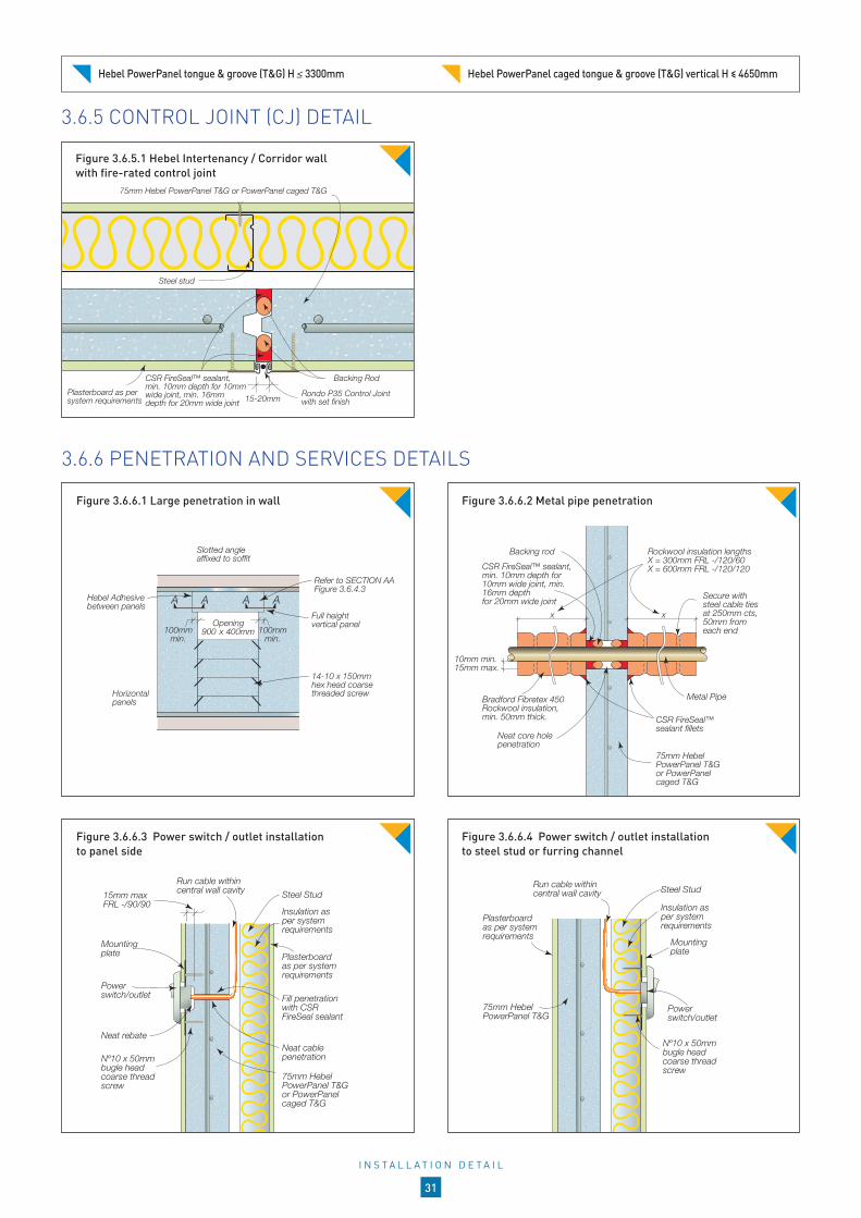
3.6.6 PENETRATION AND SERVICES DETAILS
Slotted angle affixed to soffit
Opening900 x 400mm
Full height vertical panel
Refer to SECTION AA Figure 3.6.4.3
14-10 x 150mmhex head coarsethreaded screwHorizontal
panels
100mm min.
100mm min.
Hebel Adhesivebetween panels
AA AA
CSR FireSeal™ sealant, min. 10mm depth for 10mm wide joint, min. 16mm depthfor 20mm wide joint
Backing rod Rockwool insulation lengths X = 300mm FRL -/120/60 X = 600mm FRL -/120/120
Secure with steel cable ties at 250mm cts, 50mm from each end
Neat core hole penetration
Metal Pipe
CSR FireSeal™ sealant fillets
10mm min.15mm max.
x x
Bradford Fibretex 450 Rockwool insulation, min. 50mm thick.
75mm Hebel PowerPanel T&G or PowerPanel caged T&G
Mounting plate
Power switch/outlet
Neat rebate
Fill penetration with CSR FireSeal sealant
Neat cable penetration
15mm max FRL -/90/90
Insulation as per system requirements
Run cable within central wall cavity Steel Stud
Plasterboard as per system requirements
75mm Hebel PowerPanel T&G or PowerPanel caged T&G
Nº10 x 50mm bugle head coarse thread screw
Mounting plate
Power switch/outlet
Insulation as per system requirements
Run cable within central wall cavity
Plasterboard as per system requirements
75mm Hebel PowerPanel T&G
Nº10 x 50mm bugle head coarse thread screw
Steel Stud
Figure 3.6.6.1 Large penetration in wall Figure 3.6.6.2 Metal pipe penetration
Figure 3.6.6.3 Power switch / outlet installation to panel side
Figure 3.6.6.4 Power switch / outlet installation to steel stud or furring channel
CSR FireSeal™ sealant, min. 10mm depth for 10mm wide joint, min. 16mm depth for 20mm wide joint
Rondo P35 Control Joint with set finish
Backing Rod
Plasterboard as per system requirements
Steel stud
75mm Hebel PowerPanel T&G or PowerPanel caged T&G
15-20mm
3.6.5 CONTROL JOINT (CJ) DETAIL
Figure 3.6.5.1 Hebel Intertenancy / Corridor wall with fire-rated control joint
Hebel PowerPanel tongue & groove (T&G) H 3300mm Hebel PowerPanel caged tongue & groove (T&G) vertical H ≤ 4650mm
I N S T A L L A T I O N D E T A I L
31

3.6.7 HEBEL + PVC PIPE + JOINT
Wall mounted fire collar and fire and acoustic sealant to manufacturer’s specifications
Neat core hole penetration
Plastic pipe
75mm Hebel PowerPanel T&G or PowerPanel caged T&G
Backing rod
10mm min.15mm max.
In-wall type fire collar and fire and acoustic sealant to manufacturer’s specifications
Neat core hole penetration
Plastic pipe10mm min.15mm max.
75mm Hebel PowerPanel T&G or PowerPanel caged T&G
Backing rod
Figure 3.6.7.1 Plastic pipe penetration with in-wall type fire collar
Figure 3.6.7.2 Plastic pipe penetration with wall mounted fire collar
Hebel PowerPanel tongue & groove (T&G) H 3300mm Hebel PowerPanel caged tongue & groove (T&G) vertical H ≤ 4650mm
75mm HebelPowerPanel T&G or PowerPanel caged T&G
75mm HebelPowerPanel T&G or PowerPanel caged T&G
CSR FireSeal™ sealant,min. 10mm depth for 10mm wide joint,min. 16mm depth for 20mm wide joint
Fire Damper use Intumescent type or Fusible link type as determined by consulting mechanical engineering
Damper angles bolted to both sides of damper perimeter, to manufacturer’s specification.
Backing rod
10mm min15mm max
Figure 3.6.6.6 Fire damper penetration
NOTE: Appropriate project consultant to approve installation detail to satisfy project’s acoustic & fire performance requirements.
Neat cable penetration
14-10 x 65mm hex head type 17 screw
CSR FireSeal™ sealant, min. 10mm depth for10mm wide joint,min. 16mm depth for 20mm wide joint
75mm Hebel PowerPanel T&G or PowerPanel caged T&G
Concrete soffit
Steel Stud
Backing rod
Fill penetration with fire and acoustic rated sealant
fix angle to soffit slab to project specifications
Plasterboard as per system requirements
Figure 3.6.6.5 Cable installation within the cavity for switch / outlets located on both sides of wall
I N S T A L L A T I O N D E T A I L
32

Slotted angle 75mm x 50mm x 1.2mm BMT
Hebel Mortar
14-10 x 100mm MP bugle head screw, 2 per panel min 50mm from panel edges
75mm Hebel PowerPanel caged T&G
Fix angle to slab as per project specifications Concrete slab
Fix angle to slab as per project specifications
Hebel Mortar
Concrete slab
14-10 x 65m hex head type 17 screws, 2 per panel, min 50mm from panel edges
75mm Hebel PowerPanel caged T&G
Slotted angle 75mm x 50mm x 1.2mm BMT
Figure 3.7.1.4 Alternate base angle connection for installation from one side only
Figure 3.7.1.3 Base connection
3.7 CONSTRUCTION DETAILS: FRL UP TO -/120/120
3.7.1 VERTICAL PANEL INSTALLATION: HEAD, BASE AND SIDE DETAILS
Slotted angle 75mm x 50mm x 1.2mm BMT
10mm min20mm max
Con
cret
e co
lum
n/w
all
14-10 x 65mm hex head type 17 screws at 900mm max cts, installed centrally in the slots (min 3 per panel height)*
75mm Hebel PowerPanel caged T&G
CSR FireSeal™ sealant,min. 10mm depth for 10mm wide joint,min. 16mm depth for 20mm wide joint
Backing rod
Fix angle to slab as per project specifications
Figure 3.7.1.5 Vertical edge connection
*If screw is unable to be fixed, ensure panels are braced until sealant side covering angle can be installed, sim to Figure 3.7.1.2
Concrete soffit
10mm min 20mm max
Slotted angle 75mm x 50mm x 1.2mm BMT
CSR FireSeal™ sealant,min. 10mm depth for 10mm wide joint,min. 16mm depth for 20mm wide joint
Backing rod
75mm Hebel PowerPanel caged T&G
SHAFT
Covering angle
14-10 x 65mm hex head type 17 screws, 2 per panel installed in the bottom of the slots, min 50mm from panel edges*
Fix angle to slab as per project specifications
Slotted angle 75mm x 50mm x 1.2mm BMT
Max. 6000mm between joints
SlabHebel Mortar
Slab
Max. 4650mm
Wall/Column
CSR FireSeal™sealant
Hebel Adhesivebetween panels
Figure 3.7.1.2 Head connectionFigure 3.7.1.1 Vertical installation Maximum wall height 4.65m
* If screw is unable to be fixed, ensure panels are propped until sealant side covering angle can be installed
Hebel PowerPanel caged tongue & groove (T&G) vertical H ≤ 4650mm
I N S T A L L A T I O N D E T A I L
33

3.7.2 HORIZONTAL PANEL INSTALLATION: HEAD, BASE AND SIDE DETAILS
Slotted angle 75mm x 50mm x 1.2mm BMT
Hebel Adhesivebetween panels
Max. 4800mm between joints
SlabHebel Mortar
Slab
Max. 30m*
Wall/Column
CSR FireSeal™sealant
Concrete soffit
Slotted angle 75mm x 50mm x 1.2mm BMT
CSR FireSeal™ sealant,min. 10mm depth for 10mm wide joint,min. 16mm depth for 20mm wide joint
Backing rod
75mm Hebel PowerPanel caged T&G
SHAFT
10mm min 20mm max
Covering angle
14-10 x 100mm hex head type 17 screw (recessed) located 150mm from panel ends and at panel midspan
Fix angle to slab as per project specifications
Figure 3.7.2.1 Horizontal installation maximum wall height 30m
Figure 3.7.2.2 Head angle connection
Con
cret
e co
lum
n/w
all
Slotted angle 75mm x 50mm x 1.2mm BMT
14-10 x 65mm hex head type 17 screw. For up to 300 wide panels locate centrally, otherwise install 2 screws per panel min 50mm from edges, installed centrally in the slots*
75mm Hebel PowerPanel caged T&G
CSR FireSeal™ sealant,min. 10mm depth for 10mm wide joint,min. 16mm depth for 20mm wide joint
Backing rod
Fix angle to slab as per project specifications
10mm min20mm max
Con
cret
e co
lum
n/w
all
Slotted angle 75mm x 50mm x 1.2mm BMT
75mm Hebel PowerPanel caged T&GFix angle to slab
as per project specifications
10mm min20mm max
CSR FireSeal™ sealant,min. 10mm depth for 10mm wide joint,min. 16mm depth for 20mm wide joint
Backing rod
14-10 x MP bugle head screws at100mm cts, installed centrally in slots
Fix angle to slab as per project specifications
Hebel Mortar
Concrete slab
14-10 x 65mm hex head type 17 screw located 150mm from panel ends and at midspan
75mm HebelPowerPanel caged T&G
Slotted angle 75mm x 50mm x 1.2mm BMT
Slotted angle 75mm x 50mm x 1.2mm BMT
Hebel Mortar
14-10 x 100mm MP bugle head screw located 150mm from panel ends and at midspan
Concrete slab
75mm Hebel PowerPanel caged T&G
Fix angle to slab as per project specifications
Figure 3.7.2.3 Base angle connection Figure 3.7.2.4 Alternate base angle connection for installation from one side only
Figure 3.7.2.5 Vertical edge connection Figure 3.7.2.6 Unlimited height connection for horizontal panel installation only
*If screw is unable to be fixed, ensure panels are braced until sealant side covering angle can be installed, sim to Figure 3.7.2.2
*See Figure 3.7.2.6 for unlimited height detail
Hebel PowerPanel caged tongue & groove (T&G) horizontal H ≤30m See Fig. 3.7.2.6 for unlimited height detail
I N S T A L L A T I O N D E T A I L
34

Base angle fixed to slab
Hebel Adhesivebetween panels
Concrete soffit
300-1500mm
Max. 1200mm
Max. 600mm
Max
. 465
0mm
Aperture
14-10 x 65mm hex head type 17 screws at 100mm cts
Head angle fixed to soffit
75mm Hebel PowerPanel caged T&G
14-10 x 150mm hex head Type 17 screws, fixed 100mm from panel ends
100mm min lintel seating either side of penetration
Perimeter angle, slotted 75mm x 50mm x 1.2mm BMT. Snip and fold at corners.
Concrete slab
Figure 3.7.3.6 Large penetration in wall: option 2
3.7.3 VERTICAL JUNCTION DETAILS
14-10 x 150mm hex head type 17 screwsVertical installation: screws at 900mm max cts and 100mm max from panel ends (min 3 per panel height)Horizontal installation: 2 Screws per panel. Protect recessed screws with Hebel Adhesive
Hebel Adhesive between panels
75mm Hebel PowerPanel caged T&G
Base angle fixed to slab
Concrete soffit
Hebel Adhesivebetween panels
300-1500mm
Max. 1200mm
Max. 600mm
Max
. 465
0mm
Aperture
14-10 x 65mm hex head type 17 screws at 100mm cts, min 2 per panel
Head angle fixed to soffit
75mm Hebel PowerPanel caged T&G
14-10 x 150mm hex head Type 17 screws, fixed 100mm from panel ends
100mm min lintel seating either side of penetration
Perimeter angle, slotted 75mm x 50mm x 1.2mm BMT. Snip and fold at corners.
Concrete slab
75mm Hebel PowerPanel caged T&G
Hebel Adhesive between panels
14-10 x 150mm hex head type 17 screwsVertical installation: screws at 900mm max cts and 100mm max from panel ends (min 3 per panel height)Horizontal installation: 2 Screws per panel. Protect recessed screws with Hebel Adhesive
Hebel Adhesive between panels
75mm Hebel PowerPanel caged T&G
Hebel Adhesive between panels
14-10 x 150mm hex head Type 17 screws at 900mm max cts and 100mm max from panel ends (min 3 per panel)
Cut long edges to suit splay angle
Protect recessed screws with Hebel Adhesive
75mm Hebel PowerPanel caged T&G
Figure 3.7.3.4 T-junction for vertical or horizontal installation
Figure 3.7.3.5 Large penetration in wall: option 1
Figure 3.7.3.3 Corner junction for vertical or horizontal installation
Figure 3.7.3.1 Tongue and groove junction for vertical or horizontal installation
Figure 3.7.3.2 Splay corner junction for vertical panel installation only
Adjust width of lintels 100mm each side of penetration Adjust width of lintels 100mm each side of penetration
Hebel PowerPanel caged tongue & groove (T&G) horizontal H ≤30m Hebel PowerPanel caged tongue & groove (T&G) vertical H ≤ 4650mm
I N S T A L L A T I O N D E T A I L
35

4.1 DELIVERY AND STORAGE
UNLOADING PANELSPanels must be unloaded and moved with only approved lifting devices. Before use, the lifting devices should be checked for the required lifting tags. Panels should be unloaded as close as possible to the intended installation area. This will increase work efficiency and minimise the need for secondary lifting.
STORAGEAll materials should be kept dry and preferably stored undercover. Care should be taken to avoid sagging or damage to ends, edges and surfaces.
All Hebel products must be stacked on edge and properly supported off the ground, on a level platform. Panel bundles can be stacked two high.
The project engineer should be consulted as to the adequacy of the structure to support the stacked bundles. Each bundle contains ten PowerPanels. Where bundles are stacked two high the supporting cleats must be vertically aligned to ensure minimal bending of the lower panels. (see Figure 4.1.1). If Hebel PowerPanels are stored outside they must be stored off the ground and protected from the weather.
To provide a level surface we recommend placing temporary joists beneath the supporting cleats.
Figure 4.1.1 Stacking bundles of Hebel PowerPanel
Unstrapping bundles without appropriate bracing.
Unstrapping bundles without appropriate bracing.Note: Secondary handling increases the risk of panel damage.
The repair of damage sustained during lifting and moving is the responsibility of the lifter. Where damage is excessive, panels must be replaced.
Temporary joists may be required on uneven ground
Sash clamp*
Panel lengthPanel
thickness
PanelWidth
PanelWidth
H A N D L I N G , S T O R A G E A N D R E S P O N S I B I L I T Y
36

4.2 PANEL HANDLING
MANUAL HANDLINGHebel recommends using a trolley or other mechanical apparatus to move the panels around the work site. Manual handling where people physically move a panel should be kept to a minimum, with the weight being supported by an individual kept as small as possible. Any concerns regarding the weight to be handled should be discussed with the panel installation contractor.
To minimise the possibility of manual handling injuries Hebel suggests the following:
use mechanical aids such as trolleys, forklifts, lifters, cranes and levers, or team lifting to move panels
keep the work place clean to reduce the risk of slips, trips and falls, which can cause injury
plan the sequence of installation to minimise panel movements and avoid awkward lifts
train employees in good lifting techniques to minimise the risk of injury.
TROLLEY ASSISTED HANDLINGHebel has developed a trolley to allow easier and safer handling of Hebel PowerPanel onsite. There is a range of trolleys to suit panels from 1.2m to 4.2m in length.
HEALTH AND SAFETYHebel products are cement-based which may irritate the skin resulting in itching and occasionally a red rash. The wearing of gloves and suitable clothing to reduce abrasion and irritation of the skin is recommended when handling Hebel products.
Approved respirators (AS/NZS1715 and AS/NZ1716) and eye protection (AS1336) should be worn at all times when cutting and chasing. Refer to the Hebel Material Safety Data Sheets.
Refer to the back page of this Design and Installation Guide for further information regarding health and safety.
Figure 4.2.3 Standard personal protection equipment (PPE).
Figure 4.2.2 Hebel Panel Trolleys for easier and safer handling and cutting of Hebel PowerPanels.
Figure 4.2.1 Hebel Panel Lifters are used for positioning panel in wall.
H A N D L I N G , S T O R A G E A N D R E S P O N S I B I L I T Y
37

4.3 DESIGN, DETAILING AND PERFORMANCE RESPONSIBILITIES
Hebel engages independent acoustic testing laboratories to test and report on the acoustic performance of a wall in accordance with the relevant Australian Standards. Acoustic consultants use these reports as the basis for opinions (estimates of laboratory performance) they issue for variations or different arrangements to the tested system, and also to design and specify walls that meet appropriate criteria for a particular project. Using their experience, the acoustic consultant will make judgements about onsite installed performance of various walls. The performance levels of walls documented in this Design and Installation Guide are either what is reported in a test or the documented opinion of an acoustic consultant.
Responsibility for acoustic performance in projects is typically:
PROJECT ACOUSTIC CONSULTANT: Opinions on expected laboratory performance of wall configurations that vary from actual test configuration such as substitution products and components.
Judgements about expected field performance using laboratory test reports and practical experience.
Design, specification and certification of acoustic performance for individual projects. This involves the design and selection of building elements, such as walls and floors and their integration in the building considering the following:
• Interface of different building elements and to the structure/substrate
• Wall junctions
• Penetrations
• Flanking issues
• Room/building geometry
• Acoustic field testing
PROJECT CERTIFIER &/OR BUILDER: Identifying the acoustic performance requirements for the project in accordance with the National Construction Code (NCC) and clearly communicating this to relevant parties.
Applicability of any acoustic information supplied by CSR Hebel including tests and opinions for the project.
The project acoustic consultant’s responsibilities detailed above if one is not engaged in the project.
CSR Hebel does not provide acoustic consulting services and does not offer acoustic advice. CSR Hebel only provides information that has been prepared by others and CSR Hebel therefore shall not be considered experts in the field. Any party using the information contained in this Design and Installation Guide or supplied by CSR Hebel in the course of a project must satisfy themselves that it is true, accurate and appropriate for the application, consequently accepting responsibility for its use. CSR Hebel is not responsible for the acoustic performance of constructed walls, including field performance, and does not interpret or make judgements about acoustic performance requirements in the National Construction Code (NCC).
The above is applicable to other design criteria such as fire and structure.
H A N D L I N G , S T O R A G E A N D R E S P O N S I B I L I T Y
38

5.1 APPENDIX 1
PowerPanel physical properties1. Nominal dimensions and profiles of standard
and custom Hebel PowerPanel are shown in Section 1.11.
2. Standard Hebel PowerPanel has a single layer of steel reinforcement consisting of 4 longitudinal bars of 5mm diameter.
3. Custom Hebel PowerPanel has a single or double layer of steel reinforcement consisting of 4 or 5 longitudinal bars of 5mm diameter.
4. Nominal dry density = 510kg/m3.
5. Average working density = 663kg/m3 at 30% moisture content.
6. Average service life density = 561kg/m3 at 10% moisture content.
7. For custom PowerPanel average working density =707kg/m3 at 30% moisture content.
PowerPanel strength properties1. Characteristic compressive strength, f’m = 2.8 MPa.
2. Average compressive strength = 3.2 MPa.
3. Characteristic Modulus of Rupture, f’ = 0.60 MPa.
PowerPanel fire rating propertiesFor FRL ratings of Hebel PowerPanel internal walls refer to fire opinions: 26095-13 and 27915-13 and Fire Test Report FSV-0979.
PowerPanel acoustic propertiesHebel PowerPanel with no plasterboard or other lining Rw = 36dB (refer to ATF-676 test and PKA-201006C02 opinion).
PowerPanel thermal propertiesR-Value of Hebel PowerPanel with no plasterboard or other lining = 0.375m2K/W at 14% moisture content.
A2 TERMINOLOGY AND ASSESSMENT METHODSWeighted Sound Reduction Index (Rw)Australian building regulations have adopted the European acoustic rating system, the ‘Weighted Sound Reduction Index’ (Rw), which is the International Standard. The Rw value replaces the former ‘Sound Transmission Class’ (STC) as a measure of the acoustic performance of a wall.
Ctr Adaptation TermThe Rw provides a convenient single number performance rating for ‘normal’ sounds such as speech. Where low frequency sound insulation performance is important, as may be the case with traffic noise or music and DVD systems, a correction factor is added to the Rw number. This factor de-rates the wall system’s performance according to its ability to insulate low frequency sound. The factor is called Ctr and it is a negative value. Therefore, a wall having an Rw of 55dB with a Ctr of –5dB has an Rw+Ctr rating of 50dB.
Impact Sound TransferImpact sound is caused by vibrations, which are transferred directly through the wall and re-radiated as sound in the adjacent room. These sound vibrations can be generated by actions such as closing of a cupboard door.
The transfer of impact sound can be minimised by ensuring no mechanical connection exists between the two sides of the wall. For impact rated walls the BCA requires walls to be of ‘discontinuous construction’. This refers to a wall maintaining a minimum 20mm cavity between two separate leaves except at the periphery.
Test reportsAll acoustic test reports have been issued by the National Acoustic Laboratory or other NATA Registered Laboratories. All fire test reports have been issued by CSIRO. Test reports quoted in this Design and Installation Guide are available on request from CSR Hebel.
Sound insulation estimatesAcoustic consultants often use computer models to determine sound transmission estimates for specific wall system configurations. These are known as ‘Acoustic Assessments’ or ‘Acoustic Opinions’.
The computer model predicts the Rw performance expected from a laboratory test on the system. All acoustic opinions quoted in this Design Guide are available on request from CSR Hebel.
Fire Resistance Level (FRL) indexThe Fire Resistance Level (FRL) of the systems detailed in this Design and Installation Guide have been determined from CSIRO, Exova and BRANZ fire opinions based on testing conducted at the CSIRO laboratories in North Ryde.
The FRL rating consists of three performance criteria, structural adequacy / integrity / insulation. For non-load bearing walls, there is no requirement for ‘structural adequacy’ rating. For example, the FRL of a non-load bearing wall may be expressed as -/120/90 where the ‘dash’ indicates no rating for a ‘structural adequacy’ rating, followed by ‘integrity’ for 120 minutes and ‘insulation’ for 90 minutes.
These tests and opinions refer to a range of wall heights. Please refer to FRL values for the selected systems in this Design and Installation Guide.
Acoustic and fire testsAll tests performed on CSR Hebel walls have been done in accordance with relevant Australian Standards at the time of testing.
HEBEL POWERPANEL MATERIAL PROPERTIES
A P P E N D I X
39


THE BETTER WAY TO BUILDHebel is a quality building product, and is backed by CSR Building Products Limited.
For more information visit our website:
www.hebel.com.au
For sales enquiries or further information, please telephone us from anywhere in Australia:
1300 369 448
Health & safety Information on any known health risks of our products and how to handle them safely is on product packaging and / or the accompanying documentation.Additional information is listed in the Material Safety Data Sheet (MSDS). To obtain a copy of a MSDS, download from www.hebel.com.au. Contractors are required by law to perform their own risk assessments before undertaking work.
Performance & certification Hebel® products and systems are developed in Australia by CSR Building Products. ABN. 55 008 631 356. It is a manufacturer and supplier of Hebel Autoclaved Aerated Concrete (AAC) products. Because it is a manufacturer and supplier only, CSR does not employ people qualified as Accredited or Principal Certifiers.CSR is therefore unable to provide Construction Compliance Certificates or Statements of Compliance. CSR conducts appropriate testing of its products and systems to determine performance levels. These include structural, fire and acoustic tests. Testing is conducted and certified by appropriate specialists in these fields. When using Hebel products and systems in specific projects, such specialists should be consulted to ensure compliance with the Building Code of Australia and relevant Australian Standards.
Disclaimer Information presented in this document is supplied in good faith and to the best of our knowledge was accurate at the time of preparation. The provision of this information should not be construed as a recommendation to use any of our products in violation of any patent rights or in breach of any statute or regulation. Users are advised to make their own determination as to the suitability of this information in relation to their particular purpose or specific circumstances. Since the information contained in this document may be applied under conditions beyond our control, no responsibility can be accepted by CSR‚ or its staff for any loss or damage caused by any person acting or refraining from action as a result of misuse of this information.
OtherThe design of a wall, floor or fence system requires the services of professional consultants. This document has been prepared as a source of information to provide general guidance to those consultants – and in no way replaces the services of the professional consultant and relevant engineers designing the project.No liability can therefore be accepted by CSR or other parties for the use of this document. Hebel products and systems undergo constant research and development to integrate new technology and reflect ongoing performance enhancement.Hebel systems are constantly reviewed so as to reflect any changes in legislative building requirements and or general developments in common building practice, due to our commitment to continual development and improving our building systems.We advise that all users of this document should regularly check that this document is current, and they are applying our latest design information.The latest editions of our documents are available on our website: www.hebel.com.au
Hebel® is a registered trademark of the Xella group. CSR Building Products Ltd is an exclusive licensee of Xella. CSR Hebel is a business of CSR Building Products Ltd ABN 55 008 631 356.
CSR, PowerPanel®, PowerClad®, Hebel Block®, PowerFloor®, Hebel Floor®, PowerFence®, HighBuild®, are registered trademarks of CSR Building Products Limited.
CSR HEBELTriniti 3, 39 Delhi RoadNorth Ryde NSW 2113, AustraliaTelephone +61 2 9235 8000
HELIT117 March 2020