corrosion concepts - fudan...
TRANSCRIPT

Materials and Corrosion 2009, 60, No. 11 DOI: 10.1002/maco.200805198 899
Corrosion ConceptsIn this forum readers will be able to present practical problems
for discussion. It is envisaged that these contributions will
include not only discussion of general problems and incidents of
corrosion but that suggested remedies will also be presented and
discussed. It is hoped that this exchange of knowledge and
experience will become a permanent feature of this periodical.
We are particularly anxious that both Senior Scientists and those
with more practical experience will make use of this forum to
exchange information, problems and potential remedies.
Pitting corrosion on 316L pipes in terephthalic acid (TA) dryer
Y. Gong, J. Cao, X.-H. Meng and Z.-G. Yang*
Grade 316L is a type of austenitic stainless steel with ultra-low carbon
content and it exhibits superior corrosion resistance. However, pitting is
always observed in 316L steel when it is exposed to media containing
halide ions. In the present study, we found that in the presence of acetate
acid (HAc) containing chloride or bromide ions, pitting occurred on the surface
of the rotary steam pipes with the matrix material of 316L steel in
terephthalic acid (TA) dryer. In order to identify the causes of the failure,
metallographic structures and chemical compositions of the matrix material
were inspected by an optical microscope (OM) and a photoelectric direct
reading spectrometer. Beside these, scanning electron microscopy (SEM)
and energy dispersive spectroscopy (EDS) as well as ion chromatography (IC)
were used to analyze the micromorphologies of the corrosion pits and the
chemical compositions of the corrosion deposits within them. Analysis of the
results revealed the sources of halide ions and the factors accelerating the
corrosion rate. Beside these, detailed mechanisms of pitting were discussed and
six out of all the seven theoretical morphologies of pitting features were
obtained in practice.
1 Introduction
Purified terephthalic acid (PTA) has wide applications in a variety
of fields in our daily life, such as chemical fiber industry, light
industry, electronics industry, and so on. Besides polyester bottle
chips, polyester films, and polyester fibers, over 90% of the
application of PTA is as the raw material to manufacture
polyethylene terephthalate (PET) [1], one of the most widely used
engineering plastics in the world. There are now two primary
methods formanufacturing PTA,which are namelyWitten process
and Amoco process [2]. The Witten process was developed in the
50s of the 20th century, and thanks to its superior qualities such as
simple and mature process, reliable technique, low corrosiveness,
Y. Gong, J. Cao, X.-H. Meng, Z.-G. Yang
Department of Materials Science, Fudan University, No. 220 Handan
Road, Shanghai 200433 (P. R. China)
E-mail: [email protected]
www.matcorr.com
etc., it is still themost widely appliedmethod currently available for
manufacturing terephthalic acid (TA). However, the purity of the
products produced by the Witten process is not ideal owing to the
lack of purification procedures. The Amoco process is a relatively
new method that can purify TA products immediately after
obtaining the crude TA (CTA). Hence, the Amoco process has
presently become more and more popular in many countries due
to its simplified purification procedures [3].
The Amoco process has three major stages [4]:
� M
anufacturing CTAAt this stage, the raw material para-xylene (PX) is oxidized in
the atmosphere of oxygen or oxygen-rich air to produce
TA, with cobalt acetate (Co(Ac)2) and manganese acetate
(Mn(Ac)2) as catalysts, tetrabromoethane (C2H2Br4) as the
co-catalyst, and acetate acid (HAc) as the medium. Owing to
its high content of impurities, particularly the byproducts, the
� 2009 WILEY-VCH Verlag GmbH & Co. KGaA, Weinheim

900 Gong, Gao, Meng, and Yang Materials and Corrosion 2009, 60, No. 11
TA product obtained during this stage is called CTA. Detailed
reaction conditions and the chemical formula are shown in
equation (1).
(1)
� P
Figure
� 200
urifying CTA to PTA
The main byproduct of CTA produced in the oxidation stage
is 4-carboxyl benzaldehyde (4-CBA). For the purpose of
purification, 4-CBA is hydrogenated in hydrogen atmosphere
to form soluble para-toluic acid (P-TA) in this stage, as seen in
equation (2). By dissolving the P-TA in hot water, PTA is obtained.
Meanwhile, the P-TA separated from CTA is also collected and
recycled for further oxidation to produce PTA.
(2)
� P
ost-treatment of PTAThe so-called PTA obtained in the purification stage is far
from the requirements of finished products. The wet PTA cakes
must undergo some post-treatments at this stage, such as
crystallization, drying, and packing for conversion into PTA
powder.
1. Schematic diagram of TA oxidation (CTA manufacturing) proce
9 WILEY-VCH Verlag GmbH & Co. KGaA, Weinheim
In fact, there are several subsequent procedures also needed
at stage 1 to get CTA, including centrifugation, filtering, and
drying. Figure 1 presents the schematic view of the detailed
procedures in stage 1 for manufacturing CTA in the industry.
However, as is shown in equation (1), the complicated oxidation
catalyst system may inevitably introduce a harmful environment
involving bromide ions and HAc into the post-oxidation
equipments such as TA centrifuge, vacuum filter, and a TA
dryer. Furthermore, the alkali liquor (commonly 3% NaOH
solution) applied to wash these equipments often contains some
impurities, particularly chloride ions, which may cause even
greater harm together with the existence of bromide ions and
HAc. Therefore, various kinds of failures were frequently
observed in TA centrifuge and TA dryer in the past during
routine downtime.
316L stainless steel always suffers pitting corrosion in the
presence of a medium containing halide ion [5, 6]. In this paper,
we report various types of degradations such as pitting corrosion,
crevice corrosion, flow-accelerated corrosion (FAC) and so on that
were detected on some 316L steam pipe surfaces in the TA dryer
of a CTA manufacturing device during an Amoco process in a
petrochemical company in Shanghai. Among them, pitting
corrosion was a major concern due to the serious harm it causes
and its frequent occurrence on the pipes. The expected life of
the TA dryer under the operating conditions was about 8 years,
but some of its steam pipes failed due to pitting within just 2 years
(from September 2004 to March 2007). Thus, detailed investiga-
tions from three aspects, matrix materials, process media, and
service conditions were conducted on the pitting pipe, failure
including macro and micromorphology observation on corrosion
pits, and chemical composition analysis of the corrosion deposits
in the pits. On the basis of the analysed results, the causes and the
mechanisms of pitting are discussed, which have an important
significance both for corrosion prevention of TA dryer in the
future and also for a better understanding of pitting corrosion in
engineering practice.
2 Experimental method and results
2.1 Visual observation
The TA dryer is a rotating cylinder with three arrays of circular
steam pipes within the cylinder. In the dryer, steam passes
ss
www.matcorr.com
Materials and Corrosion 2009, 60, No. 11 Pitting corrosion on 316L pipes 901
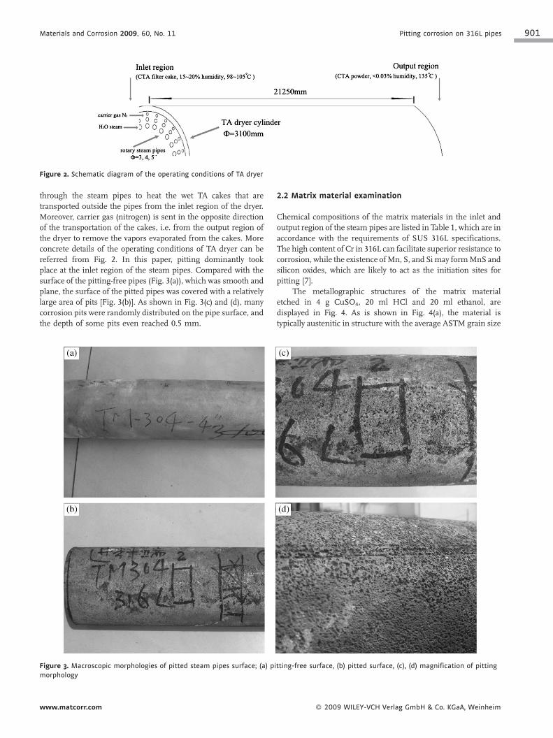
Figure 2. Schematic diagram of the operating conditions of TA dryer
through the steam pipes to heat the wet TA cakes that are
transported outside the pipes from the inlet region of the dryer.
Moreover, carrier gas (nitrogen) is sent in the opposite direction
of the transportation of the cakes, i.e. from the output region of
the dryer to remove the vapors evaporated from the cakes. More
concrete details of the operating conditions of TA dryer can be
referred from Fig. 2. In this paper, pitting dominantly took
place at the inlet region of the steam pipes. Compared with the
surface of the pitting-free pipes (Fig. 3(a)), which was smooth and
plane, the surface of the pitted pipes was covered with a relatively
large area of pits [Fig. 3(b)]. As shown in Fig. 3(c) and (d), many
corrosion pits were randomly distributed on the pipe surface, and
the depth of some pits even reached 0.5 mm.
Figure 3. Macroscopic morphologies of pitted steam pipes surface; (a) pi
morphology
www.matcorr.com
2.2 Matrix material examination
Chemical compositions of the matrix materials in the inlet and
output region of the steam pipes are listed in Table 1, which are in
accordance with the requirements of SUS 316L specifications.
The high content of Cr in 316L can facilitate superior resistance to
corrosion, while the existence ofMn, S, and Simay formMnS and
silicon oxides, which are likely to act as the initiation sites for
pitting [7].
The metallographic structures of the matrix material
etched in 4 g CuSO4, 20 ml HCl and 20 ml ethanol, are
displayed in Fig. 4. As is shown in Fig. 4(a), the material is
typically austenitic in structure with the average ASTM grain size
tting-free surface, (b) pitted surface, (c), (d) magnification of pitting
� 2009 WILEY-VCH Verlag GmbH & Co. KGaA, Weinheim

902 Gong, Gao, Meng, and Yang Materials and Corrosion 2009, 60, No. 11
Table 1. Chemical compositions of steam pipes (wt%)
Element C Si S P Mn Ni Cr Mo
Inlet region 0.014 0.738 0.007 0.030 1.044 12.088 17.436 2.046
Output region 0.015 0.748 0.006 0.031 1.063 12.331 17.429 2.035
SUS316L [42] �0.03 �0.75 �0.030 �0.045 �2.0 10.0�14.0 16.0�18.0 2.0�3.0
of about 6. Also, lot of black dots, which represent the inclusions
of MnS or silicon oxide, can be found within these coarse
austenitic grains, as seen in Fig. 4(b). Intergranular cracks were
not found in Fig. 4, which implies that stress corrosion cracking
(SCC) did not occur in this case.
2.3 SEM and EDS analyses
As shown in Fig. 5(a), densely distributed corrosion pits can be
seen on the pipes surface under scanning electron microscopy
(SEM). In some regions, with enlargement, two neighboring pits
having a diameter of about 150 mm tended to combine into a
larger pit [Fig. 5(b)], whichmay aggravate the damage on the pipe.
Figure 5(c) displays the same circumstance described in Fig. 5(b),
where the number of pits is three. The white dot-like stains in
Fig. 5(b) represent corrosion deposits.
Figure 4. Metallographic structures of steam pipes with different
magnifications
� 2009 WILEY-VCH Verlag GmbH & Co. KGaA, Weinheim
Samples were cut from the pitted region of the failure pipes
and the cross-sections of these samples were observed under
SEM. Explicit differences between the inner wall and the outer
wall of the pitted pipes can be seen in Fig. 6(a) and (b). Compared
igure 5. SEM of the pits on pipes surface; (a) total morphology,
) two-neighboring pits, (c) three-neighboring pits
F
(b
www.matcorr.com

Materials and Corrosion 2009, 60, No. 11 Pitting corrosion on 316L pipes 903
Figure 6. SEM of the cross-sections of pitted pipes
with the smooth inner wall, the outer wall was defected by some
corrosion pits, whose depth had reached about 0.4 mm. As is well
known, there are seven theoretical morphologies of pitting,
namely, narrow and deep, elliptical, wide and shallow, subsurface,
undercutting, horizontal, and vertical [8]. Schematic diagrams of
the seven theoretical morphologies are displayed in Fig. 7. In this
paper, it can be seen from Fig. 8 that six out of the seven
theoretical pitting morphologies were obtained from the pitted
pipes under SEM, which may provide a solid proof for the
Figure 7. Schematic diagram of theoretical pitting morphologies
www.matcorr.com
theoretical morphologies in practice. Indeed, the various pitting
morphologies may also have caused combined side effects on the
steam pipes.
On taking a closer look at the corrosion deposits within the
pit in Fig. 8(b), delamination can be found on the deposits, as seen
in Fig. 9. It is well known that delamination may induce the
deposits to be abrased layer by layer under the effect of flow (gas
or liquid), which may result due to the acceleration of corrosion
rate (detailed mechanisms will be discussed later). Furthermore,
chemical compositions of the corrosion deposits were detected by
energy dispersive spectroscopy (EDS). The four analysis sites are
displayed in Fig. 9 as well, and the chemical compositions are
listed in Fig. 10 and Table 2. According to the results of the
analysis, it is surprising that the contents of chlorine element
were 7.17, 5.36, 8.21, and 2.60% (wt%), respectively at sites A, B,
C, and D.Moreover, 1.90% of the content was bromine element at
site C. Hence, the EDS results verified the hypothesis proposed
above that the pitting corrosion was led by the presence of halide
ions.
2.4 Ion chromatography
In order to further testify the EDS results, ion chromatography
(IC) was also used to identify the chemical compositions of the
corrosion deposits within the pits. When dissolved in deionized
water, corrosion deposits released the chloride and bromide ions
they contained. Fig. 11 shows that the concentrations of the
chloride and the bromide ions are 10.5 and 1.0 ppm, respectively.
Although the halide ions may not induce serious corrosion with
such a low content at first, they will lead the pits to grow deep
inwards in the matrix material when it is accumulated in the pits.
Thus, the results of ion chromatography further confirmed the
causes of pitting, the halide ions.
3 Discussion
In 316L stainless steel halide ions attacking the MnS inclusions
on the steam pipes’ surface was the major cause of pitting. Two
more reasons could be attributed for this failure: whether or not
the matrix material was qualified and where the halide ions
originated. Hence, research was carried out to study three aspects
to identify the specific causes of pitting: the matrix materials, the
process media and the service conditions. According to the
analysis results, chemical compositions of the steam pipes matrix
material conformed to the SUS 316L specifications, and the
metallographic structure was typically austenite. Thus, it can be
concluded that the matrix material was qualified; in other words,
causes for the serious pitting corrosion may involve the latter two:
the process media and/or the service conditions.
As was discussed above, the process media in the TA dryer
consisted mainly of HAc, bromide ions, and chloride ions.
Furthermore, HAc and the bromide ions were generated from the
oxidation of the catalyst system, while the chloride ions were the
remnants from the NaOH alkaline wash liquor. In fact, it can be
inferred from the EDS and IC results for the chemical
compositions of the corrosion deposits that the chloride ions
were the main cause of pitting. The aggressive chloride ions
commonly have two side effects on materials: SCC and pitting
� 2009 WILEY-VCH Verlag GmbH & Co. KGaA, Weinheim

904 Gong, Gao, Meng, and Yang Materials and Corrosion 2009, 60, No. 11
Figure 8. SEM of pitting morphologies; (a) narrow and deep, (b) elliptical, (c) wide and shallow, (d) subsurface, (e) undercutting, (f) horizontal
Figure 9. SEM of the delamination morphology of corrosion deposits
within pit
� 2009 WILEY-VCH Verlag GmbH & Co. KGaA, Weinheim
corrosion. According to Suresh Kumar et al. [9], a chloride
ions concentration of not less than 10 ppm is sufficient enough to
cause SCC at temperatures above 60 8C. Why only pitting rather
than SCC was investigated at the inlet region of the steam pipes
under the environment with high chloride ions concentration at
temperature above 100 8C still needs to be explained. It is well
known that SCC is caused by the combined effects of three
factors: tensile stress, susceptible materials, and aggressive ions,
of which tensile stress is the major factor causing SCC. That the
rotary steam pipes of the TA dryer are only under the compressive
stress vertical to the pipes rather than the tensile stress along the
pipes in service may account for why SCC did not occur in
this case. Furthermore, the compressive stress was merely
0.05 kg cm�2 g�1 (about 5 kPa). So, only pitting occurred on the
surface of the steam pipes.
www.matcorr.com

Materials and Corrosion 2009, 60, No. 11 Pitting corrosion on 316L pipes 905
Figure 10. Chemical compositions of corrosion deposits; (a) site A, (b) site B, (c) site C, and (d) site D
Pitting is a kind of localized corrosion that selectively attacks
only small areas of the metal surface but can result in relatively
great damage. There is a wealth of research that had been carried
out on the detailed mechanisms of pitting [10–18]. With the
presence of halide ions, particularly chloride ions, susceptible
sites of the passive oxide film on aluminum or stainless steel
surface may be attacked by this kind of aggressive ions such as
sulfide or silicon oxide inclusions [7], precipitates of carbide,
defects on passive film and so on. As for stainless steel, especially
those containing manganese and sulfur, MnS inclusions were
always regarded as the most susceptible sites for pitting [19–29].
Pardo et al. [30] divided the pitting process initiated from MnS
into three stages. In this paper, a different three-stage mechanism
including initiation, propagation, and termination was proposed
to enrich the mechanisms of pitting.
� Initiation
Table
Eleme
Site A
Site B
Site C
Site D
�denot
www.m
Briefly speaking, the initiation stage is a process of
dissolution of MnS inclusions and formation of corrosion pits.
2. Chemical compositions of corrosion deposits (wt%)
nt C O Br Si Mo Cl Cr Mn Fe Ni
16.23 1.68 /� 1.68 4.33 7.17 19.44 1.76 39.02 6.44
17.15 2.95 /� 2.95 2.76 5.36 11.81 1.05 34.15 5.24
18.68 14.09 1.90 3.65 /� 8.21 2.39 /� 7.69 /�
18.83 5.51 /� 2.12 3.91 2.60 29.32 1.68 31.24 2.92
es the content lower than 0.5 wt%
atcorr.com
Till date, there are two controversial theories for pit nucleation
[31]: the initiation of pitting. One illustrates the competitive
adsorption between Cl� and O2�, and the other describes the
penetration of small-radius Cl� into the oxide film. In detail, the
former introduces a process in which the O2� of the oxide film is
substituted by the selectively adsorbed Cl� and then the metal
oxides are consequently converted into soluble M3þ½Cl��3complex compounds. As a result, corrosion pits are formed
with the dissolution of these complex compounds. The latter
theory accounts for pitting as the penetration of small-radius Cl�
into the passive film, below which the conductive ions produced
by Cl� cause the cation to move in a disorderly manner and make
some specific sites of the filmmaintaining a high current density.
If the electric field of the interface between the film and solution
reaches a threshold value, pitting occurs.
Figure 11. Ion chromatograph results of corrosion deposits within the
pits
� 2009 WILEY-VCH Verlag GmbH & Co. KGaA, Weinheim
906 Gong, Gao, Meng, and Yang Materials and Corrosion 2009, 60, No. 11
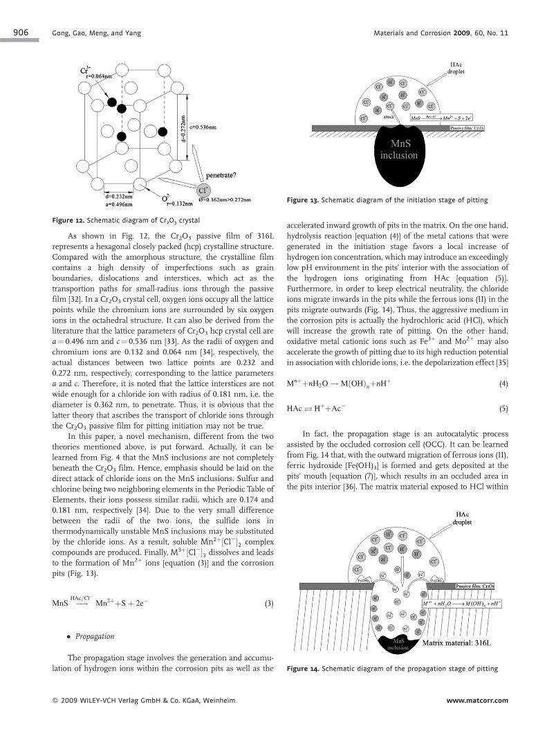
Figure 13. Schematic diagram of the initiation stage of pitting
Figure 12. Schematic diagram of Cr2O3 crystal
As shown in Fig. 12, the Cr2O3 passive film of 316L
represents a hexagonal closely packed (hcp) crystalline structure.
Compared with the amorphous structure, the crystalline film
contains a high density of imperfections such as grain
boundaries, dislocations and interstices, which act as the
transportion paths for small-radius ions through the passive
film [32]. In a Cr2O3 crystal cell, oxygen ions occupy all the lattice
points while the chromium ions are surrounded by six oxygen
ions in the octahedral structure. It can also be derived from the
literature that the lattice parameters of Cr2O3 hcp crystal cell are
a¼ 0.496 nm and c¼ 0.536 nm [33]. As the radii of oxygen and
chromium ions are 0.132 and 0.064 nm [34], respectively, the
actual distances between two lattice points are 0.232 and
0.272 nm, respectively, corresponding to the lattice parameters
a and c. Therefore, it is noted that the lattice interstices are not
wide enough for a chloride ion with radius of 0.181 nm, i.e. the
diameter is 0.362 nm, to penetrate. Thus, it is obvious that the
latter theory that ascribes the transport of chloride ions through
the Cr2O3 passive film for pitting initiation may not be true.
In this paper, a novel mechanism, different from the two
theories mentioned above, is put forward. Actually, it can be
learned from Fig. 4 that the MnS inclusions are not completely
beneath the Cr2O3 film. Hence, emphasis should be laid on the
direct attack of chloride ions on the MnS inclusions. Sulfur and
chlorine being two neighboring elements in the Periodic Table of
Elements, their ions possess similar radii, which are 0.174 and
0.181 nm, respectively [34]. Due to the very small difference
between the radii of the two ions, the sulfide ions in
thermodynamically unstable MnS inclusions may be substituted
by the chloride ions. As a result, soluble Mn2þ½Cl��2 complex
compounds are produced. Finally, M3þ½Cl��3 dissolves and leads
to the formation of Mn2þ ions [equation (3)] and the corrosion
pits (Fig. 13).
MnS �!HAc=Cl�
Mn2þþSþ 2e� (3)
� P
� 200
ropagation
Figure 14. Schematic diagram of the propagation stage of pitting
The propagation stage involves the generation and accumu-
lation of hydrogen ions within the corrosion pits as well as the
9 WILEY-VCH Verlag GmbH & Co. KGaA, Weinheim
accelerated inward growth of pits in the matrix. On the one hand,
hydrolysis reaction [equation (4)] of the metal cations that were
generated in the initiation stage favors a local increase of
hydrogen ion concentration, which may introduce an exceedingly
low pH environment in the pits’ interior with the association of
the hydrogen ions originating from HAc [equation (5)].
Furthermore, in order to keep electrical neutrality, the chloride
ions migrate inwards in the pits while the ferrous ions (II) in the
pits migrate outwards (Fig. 14). Thus, the aggressive medium in
the corrosion pits is actually the hydrochloric acid (HCl), which
will increase the growth rate of pitting. On the other hand,
oxidative metal cationic ions such as Fe3þ and Mo2þ may also
accelerate the growth of pitting due to its high reduction potential
in association with chloride ions, i.e. the depolarization effect [35]
MnþþnH2O! MðOHÞnþnHþ (4)
HAc ! HþþAc� (5)
In fact, the propagation stage is an autocatalytic process
assisted by the occluded corrosion cell (OCC). It can be learned
from Fig. 14 that, with the outward migration of ferrous ions (II),
ferric hydroxide [Fe(OH)3] is formed and gets deposited at the
pits’ mouth [equation (7)], which results in an occluded area in
the pits interior [36]. The matrix material exposed to HCl within
www.matcorr.com

Materials and Corrosion 2009, 60, No. 11 Pitting corrosion on 316L pipes 907
the pits serves as the anode due to its activated status, while
the Cr2O3 passive film outside the pits acts as the cathode. Such a
‘small anode–large cathode’ OCC will spontaneously cause the
pits to grow inwards in the matrix in a deep and narrow form.
Thus, the hydrogen ions in the pits’ interior continuously attack
the matrix to produce metal cations, which hydrolyze to generate
hydrogen ions in turn, i.e. the autocatalytic process.
Fe2þþ2OH� ! FeðOHÞ2 (6)
FeðOHÞ2þ2H2Oþ O2 ! 4FeðOHÞ3 # (7)
� Termination
The termination stage can also be defined as the repassiva-
tion of the matrix metal in the corrosion pits. According to Pardo
et al. [30], highly stable and insoluble compounds like FeMnO4and MoO3 form and cover the wall of the corrosion pits under the
condition of low pH and high potential values. As a result,
the potential values within the pits will then transfer to the
passivation region; in other words, the repassivation begins and
the pitting growth terminates.
Regarding the corrosion rate of 316L steel in the acetate acid
containing halide ions, some experiments on the corrosion depth
were carried out [37, 38]. Mattsson [39] defined the corrosion rate
of qualified stainless steel to be not more than 0.1 mmy�1.
Fig. 6(a) provides the evidence of thinning of the pitted pipes, for
a thickness of 2.74 mm compared with its original value of
3.0 mm. Service conditions of the steam pipes may be attributed
cause for such a serious thinning. As shown in Fig. 2, the steam
pipes in the inlet region of TA dryer contact both the wet TA cakes
and the carrier gas, whichmay lead to a two-phase (gas and liquid)
FAC on the steam pipes’ surface due to the high humidity of the
wet TA cakes [40, 41]. FAC is a kind of corrosion process of
chemical dissolution of metal that always leads to thinning of
pipes. That the corrosion deposits produced by aggressive liquid
on the surface will be removed layer by layer by high-flow-rate gas
may account for the acceleration effect from FAC. In this case, the
metastable pipes’ surface with delaminated corrosion deposits
within the pits (Fig. 9) was abrased by carrier gas and it eventually
resulted in thinning of its wall thickness. Thus, the cause for the
serious pitting corrosion taking place only at the inlet region
rather than at other parts of the steam pipes can be explained. The
relatively high temperature near 130 8C is also a critical factor
inducing the acceleration effect. According to Hou Feng’s [37]
experiments, the corrosion rate of 316L steel under the
environment stimulated from the actual service condition of
TA dryer (26.2% TA, 0.96% Br�, 67.11% HAc (wt%) at 110 8C)reached even 1 mmy�1. Finally it can be concluded that the
serious corrosion situation and a quite high corrosion rate on the
inlet region of steam pipes resulted from the interaction between
pitting, FAC, and high temperature.
4 Conclusions
1. C
ww
hloride ions from the NaOH alkaline wash liquor were the
primary factor for the occurrence of pitting which took place
w.matcorr.com
on the steam pipes’ surface with matrix material of standard
316L austenitic stainless steel in TA dryer.
The harsh environment, i.e. the high temperature of about
2.130 8C and the FAC effect around the inlet region of TA dryer
were the main factors for the acceleration of pitting corrosion.
The small-radius chloride ions (0.181 nm) substituting for the
3.sulfide ions (0.174 nm) of MnS inclusions and forming
the soluble Mn2þ½Cl��2 complex compounds may favor the
initiation of pitting.
Six types of pitting morphologies were obtained in engineer-
4.ing practice to prove and enrich all the seven theoretical
morphologies.
Several countermeasures such as limiting the chloride ion
5.concentration in the alkaline wash liquor under 30 ppm and
good control of the service temperature in TA dryer were
implemented to mitigate the extent of pitting.
Acknowledgements: This work was supported by both Shanghai
Petrochemical Co., Ltd. and Shanghai Leading Academic
Discipline Project (Project no. B113).
5 References
[1] H. Macarie, A. Noyola, J. P. Guyot, Water Sci. Technol. 1992,25, 223.
[2] Y.-H. Liu, R.-G. Chen, Q. Zheng, Chem. Eng. Des. 2000, 10,29 (in Chinese).
[3] N. Pernicone, M. Cerboni, G. Prelazzi, F. Pinna, G. Fagher-azzi, Catal. Today 1998, 44, 129–135.
[4] G. R. Pophali, R. Khan, R. S. Dhodapkar, T. Nandy, S.Devotta, J. Environ. Manage. 2007, 85, 1024.
[5] M. H.Moayed, M. Golestanipour,Mater. Corros. 2005, 56, 39.[6] B. R. Tzaneva, L. B. Fachikov, R. G. Raicheff, Corros. Eng. Sci.
Technol. 2006, 41, 62.[7] P. Poyet, P. Couchinave, J. Hahn, B. Saulnier, J. Y. Boos,
Mem. Sci. Rev. Met. 1975, 72, 133.[8] ASTM G46-94-1999, Standard Guide for Examination and
Evaluation of Pitting Corrosion.[9] M. Suresh Kumar, M. Sujata, M. A. Venkataswamy, S. K.
Bhaumik, Eng. Fail. Anal. 2008, 15, 497.[10] T. J. Hakkarainen, Mater. Corros. 2003, 54, 503.[11] A. Pardo, E. Otero, M. C.Merino,Mater. Corros. 2000, 51, 850.[12] G. T. Burstein, C. Liu, R. M. Souto, S. P. Vines, Corros. Eng.
Sci. Technol. 2004, 39, 25.[13] X. Shi, R. Avci, M. Geiser, Corros. Sci. 2003, 45, 2577.[14] J. K. Glenn, M. H. Gold, Arch. Biochem. Biophys. 1985, 242,
329.[15] C. R. McCall, M. A. Hill, R. S. Lillard, Corros. Eng. Sci.
Technol. 2005, 40, 337.[16] B. J. Little, P. A. Wagner, Z. Lewandowski, presented at Proc.
Corrosion ’99, NACE, Houston, USA, 1999, pp. 294.[17] P. Ernst, R. C. Newman, Corros. Sci. 2002, 44, 927.[18] P. Ernst, R. C. Newman, Corros. Sci. 2002, 44, 943.[19] B. Vuillemin, X. Philippe, R. Oltra, V. Vignal, L. Coudreuse,
L. C. Dufour, E. Finot, Corros. Sci. 2003, 45, 1143.[20] J. S. Noh, N. J. Laycock, W. Gao, B. Wells, Corros. Sci. 2000,
42, 2069.[21] A. Rossi, R. Tulifero, B. Elsener,Mater. Corros. 2001, 52, 175.
� 2009 WILEY-VCH Verlag GmbH & Co. KGaA, Weinheim

908 Gong, Gao, Meng, and Yang Materials and Corrosion 2009, 60, No. 11
[22] G. S. Eklund, J. Electrochem. Soc. 1974, 121, 467.[23] A. Szummer, Z. Szklarska-Smialowska, M. Janik-Czachor,
Corros. Sci. 1968, 8, 833.[24] M. Smialowskiy, Z. Szklarska-Smialowska, M. Rychick, A.
Szummer, Corros. Sci. 1969, 9, 123.[25] Z. Szklarska-Smialowska, A. Szummer, M. Janik-Czachor,
Br. Corros. J. 1970, 5, 159.[26] E. Lunarska, Z. Szklarska-Smialowska, M. Janik-Czachor,
Corrosion 1975, 31, 231.[27] J. Crolet, L. Seraphin, R. Tricot,Mem. Sci. Rev. Met. 1977, 74,
647.[28] J. Stewart, D. E. Williams, Corros. Sci. 1992, 33, 457.[29] M. A. Baker, J. E. Castle, Corros. Sci. 1993, 34, 667.[30] A. Pardo, M. C. Merino, A. E. Coy, F. Viejo, R. Arrabal, E.
Matykina, Corros. Sci. 2008, 50, 1796.[31] Yue Sun, Jin Hu, Corrosion and Control of Metals, Harbin
Industry University Press, Harbin, China 2003, (in Chinese).[32] D. H. Hur, Y. S. Park, Corrosion, 2006, 62, 745.[33] Yang. Li-jun, J. West. Chongqing Univ. (Nat. Sci. Edn.) 2003, 2,
9 (in Chinese).
� 2009 WILEY-VCH Verlag GmbH & Co. KGaA, Weinheim
[34] J. P. Schaffer, A. Saxena, S. D. Antolovichm et al. The Scienceand Design of Engineering Materials, 2nd edn.,McGraw-Hill,
New York 1999.[35] P. Sedek, J. Brozda, J. Gazdowicz, Eng. Fail. Anal. 2008, 15,
281.[36] K. R. Trethewey, J. Chamberlain, Corrosion for Science and
Engineering, 2nd edn., Longman, Essex 1998.[37] Hou. Feng, Xu. Hong, Xu. Linyun et al.,China Syn. Fiber Ind.
2005, 28, 34 (in Chinese).[38] A. Turnbull, M. Ryan, A. Willetts, S. Zhou, Corros. Sci. 2003,
45, 1051.[39] E. Mattsson, Basic Corrosion Technology for Scientists and
Engineers, Ellis Horwood Limited, West Sussex 1989.[40] C. Hales, K. J. Stevens, P. L. Daniel, M. Zamanzadeh, A. D.
Owens, Eng. Fail. Anal. 2002, 9, 235.[41] R. B. Dooley, V. K. Chexal, Int. J. Pres. Ves. Pip. 2000, 77,
85.[42] ASME N-708-2007, Use of JIS G4303, Grades SUS304,
SUS304L, SUS316, and SUS316L Section III, Division 1,SUPP 2.
(Received: November 20, 2008)(Accepted: December 10, 2008)
W5198
www.matcorr.com