corrosion control performance …infohouse.p2ric.org/ref/29/28275.pdfcorrosion control performance...
TRANSCRIPT

CORROSION CONTROL PERFORMANCE EVALUATION OF ACCEPTABLE ALTERNATIVES FOR CADMIUM
Mark Ingle, James Ault
Ocean City Res@
ABSTRACT
Cadmium has been identi- fied as a threat to worker health and the environment. A test program was conducted to evaluate the performance of environmentally acceptable substitutes for cadmium plat- ing. Fifteen test coatings were exposed to natural ma- rine, industrial, and rural atmospheres for 12 -months. Additional laboratory tests were conducted to determine coating abrasion resistance, adhesion, fastener breaking torque , electrochemical behavior, and resistance to stress corrosion cracking. The relative merits and limitations associated with the alternative cadmium substitutes are discussed.
INTRODUCTION
In 1990, the Headquar- ters, Army Materiel Con- mand's, Acquisition Pollution Prevention support Office determined an environmentally acceptable alternative for the widely used cyanide based cadmium plating process was required. The Army consid- ered cadmium plating a sig- nificant operational problem f o r the following reasons:
1. Cadmium, which is toxic to humans, poses a health threat to plating Process workers. The Depart- ment of Labor's occupational
ENVIRONMENTALLY PLATING
l?xFa49
arch corporation
Safety and Health Administra- tion (OSHA) is currently developing a for worker cadmium exposure. The proposed I1Standardnf will significantly decrease the acceptable cadmium "Personal Exposure Limits" and could require cadmium plating shop staff to wear respirators.(l)
2. The quantities of cadmium that may be legally discharged are being reduced by state and local environ- mental agencies. Army depots in California and Texas are having difficulty complying with their state and local government permits.
3 , Based on environ- mental and worker health concerns, other nations are restricting cadmium usage. For example, Sweden has banned cadmium as a corrosion control coating.(2) Other European and Asian nations are also exploring possible bans on specific cadmium applications.
Because Army depots apply cadmium coatings to carbon steel parts primarily to control substrate corro- sion, a test program was developed to evaluate alter- native environmentally ac- ceptable coatings. Environ- mentally acceptable coatings were selected based on the following criteria:
1
1 oz

I The Proceedings of the 79th AESF Annual Technical Conference SUWFI'N~ TBSE S M N
dun= ZZ-ZS, 1SD-Z Atlanta, Georgia
The American Electroplaters and Surface Finishers Society, Inc. (AESF) is an international, individual- membership, professional, technical and educational society for the advancement of electroplating and surface finishing. AESF fosters this advancement through a broad research program and comprehensive educational programs, which benefit its members and all persons involved in this widely diversified industry, as well as govemment agencies and the general public. AESF dissemi- nates technical and practical information through its monthly joumal, Plating and Surface Finishing, and through reports and other publications, meetings, symposia and conferences. Membership in AESF is open to all surface finishing professionals as well as to those who provide services, supplies, equipment, and support to the industry.
According to the guidelines established by AESF's Meetings and Symposia Committee, all authors of papers to be presented at SUWFIN@ have been requested to avoid commercialism of any kind, which includes references to company names (except in the title page of the paper), proprietary processes or equipment.
Statements of fact or opinion in these papers are those of the contributors, and the AESF assumes no responsibility for them.
All acknowledgments and references in the papers are the responsibility of the authors.
Published by the American Electroplaters and Surface Finishers Society, Inc. 12644 Research Parkway Orlando, FL 32826-3298 Telephone: 4071281 -6441 Fax: 407E81-6446
Copyright 1992 by American Electroplaters and Surface Finishers Society, Inc. All rights reserved. Printed in the United States of h ~ n c a . This publication may not be reproduced, stored in a retrieval system, or transmitted in whole or part, in any form or by any means, electronic, mechanical, photocopying, recording, or otherwise without the prior written permission of AESF, 12644 Research Parkway, Oliando, FL 328283298:
I
Prlnted by AESF Press
SUWFIN'is a registered trademark of the American Electroplaters and Surface Finishers Society, Inc.
1.
2.
3.
Systems must not contain more than 350-gm/liter of Volatile Organic Compounds (VOCs) . Systems cannot contain lead, chrome, or cadmi- um.
System application must not utilize a cyanide bath.
The test program goals were:
1. To identify environmen- tally acceptable coating systems that could provide effective corrosion control performance when applied to a carbon steel substrate at thicknesses similar to those listed in the Federal cadmium plating specification QQ-P- 416.
2. To develop the broadly applicable performance data required by the Army's user activities to identify envi- ronmentally acceptable alter- natives for cadmium coatings.
The corrosion control performance evaluation pro- gram included atmospheric exposure and laboratory testing. Test specimens were exposed to natural marine, industrial, and rural atmos- pheres for 12-months. The laboratory evaluations in- c l u d e d examination of coat- ing system/panel electrochem- ical responses, abrasitn resistance, and adhesion. An additional laboratory study to qualify the influence of the test coatings on sub- strate stress corrosion
cracking behavior was also performed. The entire pro- gram was completed over a period of 18-months.
TECHNICAL APPROACH
Test Matrix
Table I presents the program test matrix, a brief coating application process description, and the speci- fied test coating thickness- es. The test matrix includes organic, metallic, and ceram- ic based coating systems. Whenever possible, test coatings were applied at the thicknesses specified in
mil). Many test coatings were only applied at one or two thicknesses due to vendor concerns regarding perform- ance and or application . " _ technology limitations. Vendors were prohibited from applying coatings at thick- nesses greater than 1.0-mil.
QQ-P-416 (0.2, 0.5, and 1.0-
The chromate conversion coatings that are typically used as a post-treatment on the metallic systems listed in Table I were not applied to the program test speci- mens. The Army considers chromates environmentally unacceptable and did not want these system included in the test program.
Test Specimens
Table ii describes the standard and custom test specimens used during the program. The adhesion, abrasion, and stress corro- sion cracking test specimens
2
1100

were fabricated in compliance with guidelines described in the ASTM specifications. Figure 1 shows the llExposure Test" specimen listed in Table 11. These specimens were complex, multi-compo- nent, assemblies that includ- ed boldly exposed smooth surf aces, rough welds, high time-of-wetness regions, crevices, and a fastener (1/2-13-UNC-Fine, Grade 2). All test specimens were finished with either 400 grit blast media or 400 grit emery paper.
Program vendors received test panel sets (all four panel types) for coating using their "best practices. (I To ensure valid performance comparisons within each coating system group, vendors were required to coat the entire test specimen set using identical techniques. significant alterations to the as-received, 400-grit, test specimen surface finish- es were prohibited. Vendors were allowed to clean the test panels using non-de- structive processes such as vapor degreasing or ion bombardment. Components and test specimens were disassem- bled prior to coating and racked in such a manner as to minimize the impact of con- tact points on corrosion control performance.
Figure 1 shows an assex= bled exposure test panel. The washer was placed on the same side of the panels as the welded U-channel. The fasteners were tightened using standard wrenches; no
effort was made to avoid marring or other types of normal coating damage. To produce qualitatively com- parable fastener tensions, the coated nuts were tight- ened using the "turn-of-the- nut" method. This tensioning technique is based on "finger tighteningq1 the fastener and then rotating the nut an additional 360". This assem- bly method produces roughly uniform strain in each bolt, regardless of coating thick- ness. Because all test fasteners were the same size and-type, consistent strain could be related to consist- ent bolt tension.
Coatins Thickness Oualifica- tion Testinq
Test specimen coating layer thicknesses were meas- ured prior to exposure/labo- ratory testing. Non-magnetic coating thicknesses were measured using a non-destruc- tive Elcometer 300 film thickness gauge. Coatings exhibiting magnetic proper- ties were measured using both a micrometer technique and representative metallography. Regardless of the technique employed, coating thicknesses were measured at five widely spaced points on the front and back sides of the speci- mens. Coating thickness averages and standard devia- tions were calculated.
Exposure Testinq
Replicate panels were exposed at marine (Ocean City Research Corporation - Sea Isle, NJ), industrial (Chica-
3
1101
go, IL), and rural (Medina, OH) atmosphere test sites. At all three locations, exposure test panels were mounted at an angle of 45" on racks facing south. Panels were mounted with polymeric bushings such that runoff from any one panel would not contaminate any others. The exposure test panels were oriented such that the U- channel would trap precipita- tion and airborne debris.
Marine atmosphere expo- sure test panels were quanti- tatively inspected for sub- strate corrosion (ASTM D 610) and qualitatively examined for U-channel/fastener sub- strate degradation at monthly intervals. The ASTM D 610 technique utilizes compari- sons with visual standards to determine the area of sub- strate corrosion (coating self corrosion is not ad- dressed by the ASTM tech- niques) on a test panel. Industrial and rural exposure site test panels were in- spected using similar tech- niques after 6 and 12-months. Upon completion of the expo- sure tests, specimens were returned from all three sites to the laboratory for analy- sis. Analysis included fastener breaking torque measurements, post-exposure coating thickness determina- tions, and metallographic examination.
_.. Electrochemical tech- niques including polarization resistance and single fre- quency alternating current (AC) impedance were per-
marine atmosphere exposure test specimens at monthly intervals. Polarization resistance was used to evalu- ate the performance of the electrically conductive coating systems, while single frequency AC-impedance tech- niques were used to evaluate electrically insulating, barrier-type coatings.
To facilitate electro- chemical measurements, a 1.5- inch diameter clamp-on cell was temporarily mounted on each panel and filled with seawater. Although the test coatings were not intended for seawater immersion serv- ice, the brief seawater expo- sure period was required to facilitate electrochemical measurements. The clamp-on cells were removed as quickly as possible to minimize the seawater immersion related disruptions in the surface films generated during atmos- pheric exposure.
Polarization resistance was measured verses an SCE using a platinum counter electrode, a time based generator, an Aardvark PEC- VM high impedance voltmeter, an Aardvark PEC-AM zero resistance ammeter, and a two channel strip-chart recorder. The data collected were used to calculate corrosion rates based on established linear polarization techniques.(3) Single frequency capacitance measurements were performed using a GENRAD 1657 Digi- bridge. Parallel capaci- tance, resistance, and dissi- pation factor data were
1102
regard to system perform- ance. ( 4 )
Abrasion Testinq
Abrasion resistance was studied using a standard Taber Abraser tester (ASTM D 4060). C S - 1 7 Abrasive wheels, and a 1000-gram load were used for all tests. Because the wear resistance and density of the test coatings varied widely, the specimens were abraded to the point at which substrate steel was visible. The data collected were reported in terms of ttcycles-to-failure.
Adhesion Testinq
Adhesion tests were performed in accordance with ASTM standards D 522 and D 4145. Both standards address coating adhesion to a plasti- cally deformed substrate. Using these two standard techniques allowed a continu- um of bend diameters (0.0625 - 1.5-inch) to be studied. Results from both ASTM stand- ard techniques were converted to units of "failure diameter in inchestt to allow uniform data comparisons.
Slow Strain Rate Tests
Only selected coating systems were evaluated using the slow strain rate tech- nique. Based on the exposure test results, the six most promising alternative coating systems were selected for testing. Because some of the most promising test systems were only applied at 1.0- mils, all slow strain rate
tests were conducted on specimens with 1.0-mil thick coatings.
The slow strain rate test program was designed to examine the ability of the coating/substrate electro- chemical corrosion reactions to generate hydrogen and embrittle the high strength steel substrate. The test program was not intended as a quality control study to determine how effectively vendors removed the process hydrogen that might have been charged in a part during a plating or cleaning process. To minimize the influence of process hydrogen, the test specimens were baked at 375°F for 48-hours.
All slow strain rate tests were performed using a 6-kip load frame with a mechanical drive. The threaded specimen grips included a electrolyte con- tainer. Tests were conducted in either air, mineral oil, or an aerated solution of 3 . 5 % NaCl in deionized water. During the tests, the dis- placement and load on the frame were recorded as a function of time. When tested in the salt solution, test specimen electrochemical potential was also monitored as a function of time.
Specimens were fitted
cone based grease and sub- jected to a sufficient ten- sile load to cause a constant strain rate. Strain rates of between 1 ~ 1 0 - ~ and 1 ~ 1 0 - ~ in./sec. were used during the
i n t o the g r i p s =sing a sili-
5

program. Through replicate testing, the strain rate of 1 ~ 1 0 - ~ in./sec. was shown to effectively identify envi- ronmentally assisted cracking effects. Thus , the majority of the tests were conducted at 1x10⁻⁶ in./sec.
Fractured test specimens were inspected using a 16x optical microscope. In addition, selected fracture surfaces were metallographi- cally prepared and examined using a metallograph.
RESULTS AND DISCUSSION
Coatins System Application Thicknesses
Table I11 lists the average, actual coating thicknesses on the simple, flat test panels. Although the coating thicknesses on all test specimens were measured, the simple, flat panels were used as a basis for comparison. These simple specimens were used because they represent a "best casef1 for coating thickness appli- cation accuracy.
Given that Table I11 represents a "best case" for coating accuracy, the data show the average applied coating thicknesses deviated significantly ( - 5 8 to +152%) from those specified. In addition, the average coating thicknesses frequently devi- ated from the mean by up to 3 8 % . Surprisingly, the actual average coating thick- ness on the Cadmium test panels deviated by - 5 8 % from the specified 1.0-mil.
The Ion Vapor Deposited Aluminum (IVD Aluminum) , IVD Aluminum/Metallic Ceramic topcoat, IVD Aluminum Alloy, and Tin/Zinc coatings exhib- ited both the least deviation from the specified coating thicknesses and the least variation from the mean.
The apparent inability of vendors to apply the test coatings at the specified thicknesses is a concern. Considering the test data were collected from simple, "best case'' panels, the potential for even more significant thickness varia- tions on complex geometry parts must be addressed. Such coating thickness varia- tions could adversely affect the performance of close tolerance components.
Atmospheric Exposure Testing
Figure 2 shows a repre- sentative Cadmium coated test specimen prior to atmospheric exposure. With the exception of obvious defects on the test panels with specified 0.2-mil Electrodeposited Epoxy (E-Coat) layers, all test panels initially ap- peared uniformly coated.
Exposure Site Influence
ASTM D 610 data were collected from the marine, industrial, and rural atmos- phere exposure panels during a 12-month period to deter- mine the relative severity of the three exposure sites. Table IV shows the final, average ASTM D 610 data for the panels with the specified
6
1104

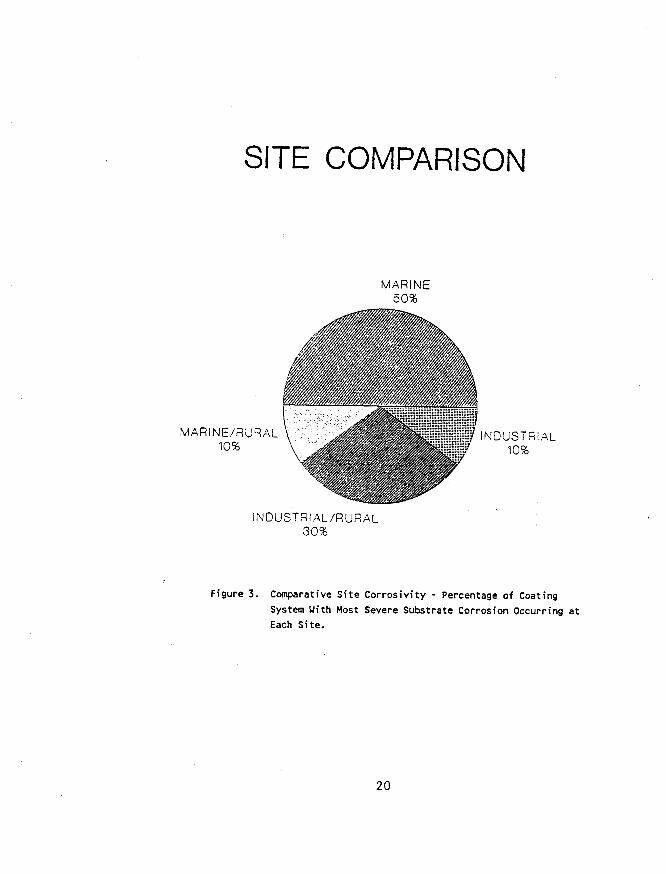
1.0-mil coatings from the three exposure sites. Due to the wide variations in coat- ing system performance, the influence of the site atmos- pheres on the coated panels was determined by comparing the percentage distribution of the lowest ASTM D 610 ratings. Because ASTM D 610 ratings are inversely related to the area of degraded substrate (a 10 rating signi- fies no substrate corrosion, a 1 rating signifies over 50% substrate corrosion), the number of times a specific site produced the lowest rating within a coating group would measure the relative site corrosivity.
Figure 3 shows the percentage distribution of lowest ASTM D 610 ratings within coating groups as a function of test atmosphere. Panels that did not exhibit substrate degradation, at any test site, were excluded from this analysis. As anticipat- ed, the marine test site was most frequently associated with the lowest ASTM D 610 rating within coating system groups. This result was not unexpected because the chlo- ride ions available at the marine site can degrade the oxide films that limit corro- sion rates on many metals. Of the remaining industrial and rural site results, most systems exhibited a Ittieg1 in which the ASTM D 610 ratings from the industrial and rural sites were identical. The performance similarities between the industrial and rural site test panels was Possibly related to the rural site's unexpectedly low pH
precipitation. Surprisingly, the precipitation pH at both the industrial and rural sites was below 4.5. (5,6) This acidic pH demonstrates the pervasiveness of the acid rain phenomenon.
The fundamental conclu- sion derived from this analy- sis was that the marine site was the most corrosive. Given that the marine atmosphere typically caused the most extensive substrate corro- sion, and as such represents the most severe corrosion control performance evalua- tion atmosphere, subsequent analyses will focus on the marine site test results.
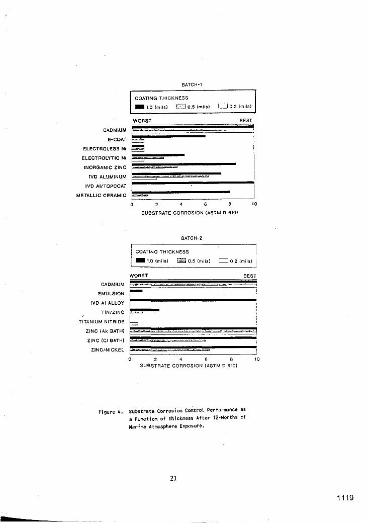
Coatinu Thickness Influence
Figure 4 shows the ASTM D 610 results, after 12- months of marine atmosphere exposure, for all fifteen test coatings as a function of specified thickness. For clarity, the results are presented in terms of the two exposure test batches. Figure 4 shows that only the panels with the Cadmium and the Zinc (Chloride Bath) coatings exhibited compara- ble, effective corrosion control performance. The Ion Vapor Deposited Aluminum (IVD Aluminum) with Metallic Ceramic topcoat and the IVD Aluminum Alloy systems also exhibited effective substrate corrosion control perform- ance. However, because these materials were only applied at the 1.0-mil layer thick- ness, their performance at thinner layers could not be determined.
7
1105
Figure 4 also shows two panels show substrate corro- coating systems that were as sion on the boldly exposed effective as Cadmium when regions, which was semi- applied at the 1.0-mil layer quantitatively evaluated thickness, but less effective using the ASTM D 610 tech- at 0.5-mils. The Zinc/Nickel nique, and degradation in and zinc (Alkaline Bath) high time-of-wetness region coating systems, when applied inside the pocket formed by at the 0.5-mil layer thick- the U-channels. Substrate ness, had ASTM D 610 ratings Corrosion in the high-time-of of approximately 6 . The 6 wetness regions was examined rating signifies that 1% of qualitatively. These quali- the substrate area was cor- tative results revealed three roded. Thus, the Zinc/Nickel important trends. First, and Zinc (Alkaline Bath) regardless of the applied coatings were almost as thickness, the Cadmium, IVD effective as the cadmium Aluminum alloy, IVD Alumi- control. num/topcoat, Zinc (Chloride
Bath), Zinc (Alkaline Bath), The Zinc/Nickel and Zinc and Zinc/Nickel coatings
(Alkaline Bath) coatings exhibited no substrate corro- exhibited an important trend sion in the high time-of- that was observed on the wetness-regions. The second remaining test coating sys- important trend observed was tems. With the exception of that the Inorganic Zinc, IVD the Cadmium and the Zinc Aluminum, a’nd Metallic Ceram- (Alkaline Bath) systems, all ic coating systems showed test coatings exhibited a significantly more substrate direct relationship between corrosion in the high time of coating thickness and sub- wetness region than on the strate corrosion control boldly exposed surfaces. The performance. In every case, third and final important thicker coating layers per- trend was that the same formed as well as or better thickness effect observed on than thinner layers. Consid- the boldly exposed surfaces ering that the cadmium con- was also observed in the trol coatings did not exhibit region above the U-channels. thickness dependent corrosion control performance, selec- The adverse affect of tion of an environmentally the U-channel on localized acceptable substitute coating substrate corrosion control system must address the performance was anticipated. thickness issue. In these regions, the elec-
trolyte was in contact with Hiqh-Time-of-Wetness Reqions the coating fer an extended Analvsis period, allowing more time
for the corrosion reactions Figure 5 shows represen- to degrade the coatings.
tative marine atmosphere However, because the cadmium exposure test panels after control system substrate did 12-months of testing. These not corrode in the U-channel
8
1106

region, th.e selection of an appropriate substitute for this service must consider the possibility of substrate corrosion in a high time-of- wetness region.
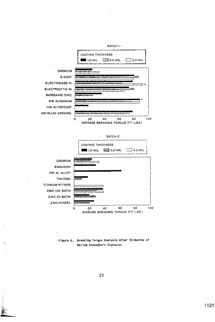
Electrolytic Ni, I V D Alu- minum, and IVD Aluminum alloy coatings all exhibited break- ing torques significantly higher than the cadmium con- trol. It is significant to note that unlike the previ-
Fastener Inspection/Breakinq ously discussed corrosion on Toraue Analvsis boldly exposed surfaces, the fastener breaking torque data
Visual inspections of the coated fasteners revealed virtually all assemblies experienced some substrate corrosion. Most frequently, corrosion was observed on the areas of the bolt over which the nut traveled during assembly and the areas of the nuts/bolts marred by the assembly wrenches. Surpris- ingly, the crevices formed at the nut/bolt interfaces did not appear corroded. Crevice corrosion, characterized by voluminous, dark corrosion product and severe substrate attack, was not observed on any test fasteners.
Figure 6 shows represen- tative breaking torque data for the Batch-1 and Batch-2 exposure test specimens. As discussed previously, the data presented in these figures are at best semi- quantitative. Only the most significant performance variations warrant discus- sion. Figure 6 shows the Cadmium, Emulsion, Inorganic Zinc, I V D Aluminum/topcoat, Tin/Zinc, Zinc (Chloride Bath), and Zinc/Nickel coat- ings exhibited essentially similar breaking torques.
These data also show the E-coat, Electroless Ni,
do not exhibit a strong thickness dependence. The observed high breaking torques are significant and were caused either by sub- strate corrosion or coating mechanical interference. Substrate corrosion caused the high breaking torques exhibited by the E-coat and Electrolytic Ni coatings.
Fasteners that e.xp e r i - enced mechanical interference are designated in Figure 6 by the tcal' character. These fasteners seized and could not be disassembled without shearing-off the nut. Metal- lographic inspection of the seized Electroless Ni coated fasteners revealed a locally thick ( > 3.0-mil) coating cutting into the steel bolt threads. The nickel coating caused deformation and frac- ture within the threaded interface. Metallographic inspection of the seized I V D Aluminum fastener interface revealed galling. The alumi- num coating was observed to have collected or cold welded together within discrete regions inside the threaded interface. Other studies designed to address coated fastener performance have also observed I V D Aluminum coated fastener galling.(7)
9
1107

The observed fastener galling, and the high break- ing torques associated with the IVD Aluminum/Al alloy fastener coatings, suggest these materials are not a direct substitute for cadmium coatings on threaded fasten- ers. More work addressing lubricants and anti-seize compounds would have to be performed before IVD A1 based coatings could be specified as a cadmium replacement on threaded fasteners.
covered with oxide, the corrosion rate fell to a relatively low value. As anticipated based on the visually observed degradation in the IVD Aluminum coatings, the corrosion rate data show a slight increasing trend during the remainder of the exposure period. This in- creasing corrosion rate correlated well with the observed corrosion spreading from pores in the IVD Alumi- num coating.
Electrochemical Analvsis
The electrochemical test data were used to confirm and interpret trends apparent in the time dependent ASTM D 610 data plots. Polarization resistance and AC impedance data were collected to facil- itate these analyses.
Figure 7 shows a repre- sentative corrosion rate plot for the IVD Aluminum coating system. Because the test data were acquired from an atmospheric exposure specimen during brief immersion in a seawater electrolyte (brief immersion is necessary to allow electrochemical data acquisition) , the data were normalized. The normaliza- tion procedure emphasizes the trends in the data and not the absolute corrosion values.
Figure 7 shows the corrosion rate varied consid- erably during the first 100- days. This was attributed to the observed oxide formation (reduced luster) on the panel surface. Once the panel was
Single frequency capaci- tance measurements also tended to confirm observed exposure test results. Figure 8 shows a representa- tive capacitance/dissipation factor plot for E-coat. The data show an increasing capacitance over the 12-month exposure period. This result is characteristic of general moisture penetration through the coating (effective de- crease in coating thickness) or an actual decrease in coating thickness (chalking). The increasing trend in the dissipation factor (D= l/R*C*W) signifies a signifi- cant decrease in resistance and is typically related to coating pores. The E-coat, emulsion, and to a lesser degree the IVD Aluminum/top- coat systems exhibited this increasing capacitance/dissi- pation factor trend. These coatings also exhibited visible corrosion products at coating pores.
The electrochemical results demonstrate an impor- tant relationship between coating chemistry and poten-
10
1108

tial cadmium substitute corrosion control perform- ance. Without exception, the proposed cadmium substi- tutes based on metals that are more electrochemically active than the substrate steel exhibited superior performance. For the layer thicknesses tested, it was apparent that sacrificial corrosion protection around pores and defects is essen- tial to ensure effective, long-term substrate corrosion protection.
Abrasion Testing
Figure 9 summarizes the average abrasion test results from three replicate test panels. Because the test coating thicknesses varied considerably, the Figure 9 data were mathematically normalized to an ideal coat- ing thickness of 1.0-mil. The normalization formula, assumed a linear relationship between coating thickness and wear resistance. Based on these normalized data, the Electroless Ni, Electrolytic Ni, and Titanium Nitride coatings provided the great- est wear resistance. These coatings were abraded for 100,000 Taber abraser cycles without the substrate steel being exposed. As an experi- mental consideration, and because of the observed cadmium control coating failure after ~ 8 0 0 0 cycles, testing was arbitrarily terminated after 100,000 cycles.
Aside from the nickel and Titanium Nitride coat-
ings, the remaining test systems exhibited signifi- cantly less resistance to abrasive wear. Of the test coating systems with less wear resistance, the Zinc/Nickel, Zinc (Alkaline Bath), Zinc (Chloride Bath), IVD Aluminum, and Tin/Zinc coatings were all more wear resistant than the cadmium control. Of these systems, the Zinc/Nickel was the most wear resistant. As antici- pated, the non-metallic coatings (E-coat, Emulsion, and Inorganic Zinc) were significantly less wear resistant than the cadmium control.
Adhesion Testing
Figure 10 presents the average adhesion test results in terms of ‘Ifailure diameter (inches)18 from three sets of test specimens. The E-coat, Emulsion, I V D Aluminum, IVD Aluminum/topcoat and Tin/Zinc coatings exhibited the small- est failure diameters. These test coatings were slightly more adherent than the Cadmi- um control. The Electroless Ni, Electrolytic Ni, Zinc (Alkaline Bath), Zinc (chlo- ride bath), and Titanium Nitride coatings were the least adherent. The apparent inverse relationship between abrasion resistance and adhesion was not unexpected because of the cm”n engi- neering property trade-off between hardness and ductili- ty. Because adhesion and ductility of the test coat- ings are evaluated by the ASTM adhesion tests used, the low-ductility, hard, wear
11
1109

resistant coatings performed Bath) coating system suggests poorly in the adhesion tests. that either the baking period
did not remove the process Slow S t r a i n R a t e T e s t i n g hydrogen or the plating layer
contributed to crack initia-
analysis of the slow strain rate test results. This Comparing the results figure shows the average time from the 3 . 5 % NaCl tests to failure for each test indicates the Cadmium coating coating system in both the caused the least substrate neutral (oil/air) and the embrittlement. The Cadmium corrosive (3.5% NaC1) test specimens' average time to electrolytes. As shown, the failure was 23.0-hours, only uncoated high strength steel 1.3-hours less than the specimens exhibited the uncoated steel. The IVD greatest time to failure in Aluminum, Tin/Zinc, and both test environments. This Zinc/Nickel coatings all result was anticipated con- exhibited times to failures sidering all of the other that were approximately 2- test coating systems were hours less than those for the more electrochemically active Cadmium coated controls. The than steel and would be fracture surfaces for these expected to generate hydrogen coating systems exhibited on exposed substrate areas. some necking (ductile behav- The uncoated steel specimens ior) with considerably more showed considerable necking shear failure than was ob- and ductility during the served on the Cadmium coated test. specimens. The remaining
test coating systems, I V D The Figure 11 neutral Aluminum/topcoat, Zinc (Alk-
test electrolyte (oil/air) aline Bath), and Zinc (Chlo- data shows only the Zinc ride Bath) exhibited times to (Alkaline Bath) appeared to failure that were considera- significantly embrittle the bly lower than those of the substrate. The Zinc (Alka- Cadmium coated controls. The line Bath) coating exhibited fracture surfaces for these a time to failure in the test specimens typically neutral environment of 15.2- showed little necking, and hours, which is significantly more shear components. Thus, lower than the time to fail- the IVD Aluminum, Tin/Zinc, ure for the other test sys- or Zinc/Nickel coating sys- tems in these media, In tems might be possible sub- addition, the fracture sur- stitutes for Cadmium over face of the Zinc (Alkaline h i g h strength steel parts, Bath) test specimen did not while the IVD Aluminum/top- exhibit any of the ductility coat, Zinc (Alkaline Bath) characteristic of the other and Zinc (Chloride Bath) neutral environment failure coatings would be considered surfaces. The premature poor choices. failure of the Zinc (Alkaline
Figure 11 presents an tion and reduced ductility.
12
1110

CONCLUSIONS
The following are the program conclusions:
1. Cadmium, IVD Aluminum/ topcoat, Zinc (Alkaline Bath), Zinc (Chloride Bath), and Zinc/Nickel coatings provide the most effective corrosion control performance in natural marine, industri- al, and rural atmospheres for a period of 12-months. IVD Aluminum based coating sys- tems, at the 1.0-mil coating thickness only, appeared to provide only slightly less effective substrate corrosion control performance than the cadmium control.
2 . The cadmium substitute test coatings applied at the 1.0-mil thicknesses typically outperformed the coatings applied at 0.2 and 0.5-mil thicknesses. The Cadmium and Zinc (Alkaline Bath) test coatings exhibited identical performance at all three application thicknesses.
3 . General trends in the exposure test data suggest that potential cadmium sub- stitutes based on metals that are more electrochemically active than the steel sub- strate will outperform barri- er and noble metal coatings.
4 . Cadmium, Emulsion, In- organic Zinc, IVD Aluminum/ topcoat, Tin/Zinc, Zinc (Alkaline Bath), Zinc (Chlo- ride Bath), and Zinc/Nickel coatings exhibited the lowest disassembly breaking torques. The remaining coating systems including IVD Aluminum and
IVD Aluminum Alloy exhibited significantly greater break- ing torques.
5. With the exception of the IVD Aluminum based proc- esses, coating system vendors were unable to apply either the cadmium controls or the alternative coatings accu- rately at the specified test thicknesses. The lack of coating system application accuracy may create signifi- cant problems for close tolerance mating surfaces or threaded fasteners requiring protective coatings.
6. Electroless Ni , Electro- lytic Ni, and Titanium Ni- tride coatings are signifi- cantly more abrasion resist- ant than the cadmium con- trols.
7. The electrodeposited epoxy, Emulsion, IVD Alumi- num, IVD Aluminum/topcoat, and Tin/Zinc coatings exhibit comparable adhesion. These coatings are slightly more adherent than the cadmium control.
8. Slow strain rate testing indicated that Cadmium is the least likely of the six coatings tested to promote environmentally assisted cracking (EAC) . The slow strain rate tests also showed that IVD Aluminum/topcoat and Zinc (Alkaline Bath) clearly increase the susceptibility of the high strength steel test specimens to EAC. The results for the IVD Aluminum, Zinc/Nickel, and Tin/Zinc coatings indicate that these materials enhance EAC suscep-
1 3
1111
tibility compared to Cadmium, als Treatments and but to a lesser degree than Processes Program Quar- the other coatings tested. terly Program Review
Meeting, August 1, REFERENCES (1991)
1.
2.
3.
4.
5.
6.
7.
OSHA Draft Cadmium Standard, Part 1910 of Title 29 of the Code of Federal Regulations, Oct., (1988)
The Swedish Ban on Cadmium, National Swed- ish Environmental Pro- tection Board Informa- tion Unit, ISBN 91-620- 3446-4, (1988)
Stern M., Geary A . , Journal of the Electro- chemical Society, Vol. 104, pp. 56, (1957)
Kendig M., Leidheiser H. Jr., Journal of the Electrochemical Society, Vol. 123, pp. 982 (1976)
Coburn S. K., et-al, Corrosiveness of Various Atmospheric Test Sites as Measured by Specimens of Steel and Zinc, Metal Corrosion in the Atmos- phere, ASTM STP-435, (1968)
Updates to the 1986 Directory of Precipita- tion Monitoring Sites - National Atmospheric Deposition Program - National Trends Network, May (1990)
Groshart E. C., Boeing Defense and Space Sys- tems Corp. Presentation to the Army Environmen- tally Acceptable Materi-
14
1112
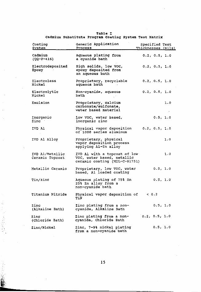
Table I Cadmium Substitute Program Coating System Test Matrix
Coating Generic Application Specified Test Svstem Process Thicknesses (m i 1 s L
(QQ-P-416) a cyanide bath
Epoxy epoxy deposited from
Cadmium Aqueous plating from 0.2, 0 . 5 , 1.0
Electrodeposited High solids, low VOC, 0.2, 0.5, 1.0
an aqueous bath
Electroless Proprietary, recyclable 0.2, 0.5, 1.0
Electrolytic Non-cyanide, aqueous 0.2, 0.5, 1.0
Nickel aqueous bath
Nickel bath
Emulsion Proprietary, calcium carbonate/sulfonate, water based material
Inorganic Low VOC, water based, Zinc inorganic zinc
1.0
0.5, 1.0
IVD A1 Physical vapor deposition 0.2, 0 . 5 , 1.0 of 1000 series aluminum
IVD A1 Alloy Proprietary, physical vapor deposition process applying Al-Zn alloy
1.0
IVD Al/Metallic IVD A1 with a topcoat of low 1.0 Ceramic Topcoat VOC, water based, metallic
ceramic coating (MIL-C-81751)
Metallic Ceramic Proprietary, low VOC, water 0.5, 1.0 based, A1 loaded coating
Tin/zinc Aqueous ?latin9 of 75% Sn 0.5, 1.0 25% Zn alloy from a non-cyanide bath
Titanium Nitride Physical vapor deposition of < 0.2 TiN
Zinc Zinc plating from a non- 0.5, 1.0 (Alkaline Bath) cyanide, Alkaline Bath
(Chloride Bath) cyanide, chloride Bath Zinc Zinc plating from a non- 0.2, 0.5, 1.0
Zinc/Nickel Zinc, 7-9% nickel plating 0.5, 1.0 from a non-cyanide bath
15
1113

Table I1 Cadmium Substitute Program Test Specimens
Specimen Overall Dimensions AIS1 Steel ASTM Reference TYDe IL x W x T inches) Grade Standards
Adhesion Test 7.00 x 4.50 x 0.03 1010 D 522, D 4145
Abrasion Test 4.00 x 4.00 x 0.12 1010 D 4060
Slow Strain 5.00 x 0.12 x 0.11 4340 E 399 Rate Test (180 k s i )
Exposure 6.00 x 4.00 x 0.25 1010 Test Custom Design
Not Applicable
Note: Unless otherwise specified in the listed ASTM standards, all specimens were finished with either 400 grit emery paper or 400 grit blast media.
1114
16

Systar
Electrodeposited Epoxy
Electroless Nickel
Electrolytic Nickel
Eml s i on
Inorganic Zinc
1W Alwninm
IVD A1 Alloy
IVD A 1 w/Topcoat
Metal 1 ic Ceramic
Ti n/Z i nc
Ti Nitride
Zinc Plate Alkaline Bath
Zinc Plate Chloride Bath
Zinc/Nickcl
Specified Thickness
0.2 0.5 1.0
0.2 0.5 1 .o
0.2 0.5 1 .o
0.2 0.5 1.0
1 .o
0.5 1 .o
0.2 0.5 1 .o
1 .o
1 .o
0.5 1 .o
0.5 1.0
<0.2
0.2 0.5 1 .o
0.5 1 .o
0.5 1 .o
Accnak
Thickness (ails)
0.21 0.39 0 .42
0.36 0.65 1.17
0.18 0.39 0.7
0.11 0.35 0.82
1 .os
1.26 1 .a2
0.29 0.47 0.91
0.99
0.86
0.52 1.37
0.53 0.91
0.093
0.16 0.46 0.84
0.43 0.88
0.35 0.56
S t a n r f a r d
Deviatim (nio
0.020 0.014 0.028
0.015 0.035 0.035
0.036 0.020 0.060
0.034 0.067 0.061
0.042
0.315 0.150
0.041 O.OS3 0.077
0.077
0.062
0.044 0.091
0.023 0.036
- - -
0.033 0.068 0.317
0.023 0.137
0.050 0.124
bevistiar f r m
slxc. C X L
5 - 22 -58
80 30 17
-10 - 22 -30
-45 -30 -18
a
152 82
C5 -6 - 9
- 1
-14
4
37
6 -9
- 20 - 8 -16
-16 -12
-30 -44
1 7
1115

Table IV Average ASTM D 610 Data for Test Panels With Specified
1.0-mil Coating Layers Exposed to the Marine, Industrial, and Rural Atmospheres for 12-months.
Atmospheric Exposure Site (Average ASTM D 610 Data)
Coatins System
cadmium E-Coat Electroless Ni Electrolytic Ni Emulsion Inorganic Zinc Ion Vapor Deposited Ai IVD A1 Alloy IVD Al/Topcoat Metallic Ceramic Tin/Z inc Titanium Nitride Zinc (Ak Bath) zinc (c1 Bath) Zinc/Nickel
Marine
10 4 1 5 1 5.5 7 10 10 6 2.5 1 10 10 10
Industrial
10 5 4 2 4
10 5
10 9
10 5
8 1
10 10
Rural
10 4 6 9 5 5
10 9
10 9 1 4
10 10 10
18
1116

r a n . i
0.S-Inch
Figure 1. Atmospheric Exposure Test Specimen.
Figure 2. Representative, As-Coated, Atmospheric Exposure Test Specimen.
19
1117
1118
SITE COMPARISON
MAR I NE/ A L' R AL 10%
MARINE 50%
N C. US 7 R I A L 10%
I N DU S T 9 I A L /R U R A L 30%
Figure 3. Comparative S i t e Corrosivity - Percentage o f Coating System With Most Severe Substrate Corrosion Occurring a t Each Site.
20
CADMIUM
E-COAT
ELECTROLESS Ni
ELECTROLYTIC Ni
INORGANIC ZINC
IVD ALUMINUM
IVD AI/TOPCOAT
METALLIC CERAMIC
COAT IN G T H I C K NE S S
1.0 (mlls) [.::I 0.5 (mils) [Ili 0.2 (mils)
I I
0 2 4 6 a 10
SUBSTRATE CORROSION (ASTM D 610)
BATCH-2
I I 1 COATING THlCKNESS I I 1.0 (mils) 0.5 (mils) 0.2 (mils) I
WORST BEST
CADMIUM r'**-- 1 *' + - ,,,_,. -,,?,,_ , . . , I
EMULSION 1-
Figure 4. Substrate Corrosion Control Performance as
a Function of Thickness After 12-Months of Marine Atmosphere Exposure.
21
1119
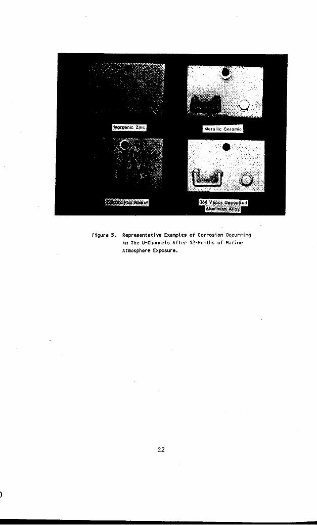
Figure 5. Representative Exanples of Corrosion Occurring in The U-Channek After 12-Months of Marine
Atmosphere Exposure.
22
BATCH-1 -
COATING THICKNESS
1.0-MIL 0.5-MIL 0.2-MIL
CADMIUM ,
ELECTROLYTIC N i y ,, x -,-,
7
IVD AI/TOPCOAT I
, ,1 ~ ,,, I I
+ i I INORGANIC ZINC
IVD ALUMINUM
I I METALLIC CERAMIC r-" - ,
0 20 40 60 80 100 AVERAGE BREAKING TORQUE (FT.-LBS.l
BATCH-2
COAT IN G T H I CKN E SS
CADMIUM c EMULSION 1
I IVD AL ALLOY
TIN/ZINC
TITANIUM NITRIDE
ZINC (AK BATH)
ZINC (CI BATH)
- ZINC/NICKEL p""""""-'
0 20 40 60 80 100 AVERAGE BREAKING TORQUE (FT.-LBS.)
F i g u r e 6. Breaking Torque Ana lys is A f t e r 12-Months o f
Marine Atmosphere Exposure.
23
1121

r
100
.80
.Ea
.40
.20
.oo
60
50
h
4 40 v
I I 1 1 I I 1 I 0 50 K)O 150 200 250 300 350 I 4
Tune - days
Figure 7. Normalized Corrosion Rate Data For a 1.0-mil, IVD Aluninun Coating as a Function of Time.
30
/ 20
Kl
0
1122
Figure 8. Capacitance and Dissipation Factor Data For a l.O-mi1, Electrodeposited Epoxy Coating as a Function o f lime.
24

Figure 9. Average Abrasion Test Data Normalized to a 1.O-mil Coating Thickness.
Figure 10. Average Coating Adhesion to a Plastically Deformed Substrate.
25
1123

I
COATING SYSTEM
UNCOATED STEEL
CADMIUM
IVD ALUMINUM
IVD AI/TOPCOAT
TIN/ZINC
ZINC (Ak BATH)
ZINC (CI BATH)
ZINC/NICKEL
TEST MEDIA
0 5 10 15 20 25 30 AVERAGE TIME TO FAILURE (HOURS)
Figure 11. Slow Strain Rate Test Results.
26
i
1124