corrosion of zircaloy spent fuel cladding in a repository
TRANSCRIPT
and~~~~~~~~~f
U�HI&211;
CORROSION OFZIRCALOY SPENTFUEL CLADDING INA REPOSITORY
Anna C. Fraker
U.S. DEPARTMENT OF COMMERCENational Institute of Standardsand TechnologyCenter for Materials Scienceand EngineeringMetallurgy DivisionGalthersburg, Maryland 20899
U.S. DEPARTMENT OF COMMERCERobert A. Mosbacher, SecretaryNATIONAL INSllTUTE OF STANDARDSAND TECHNOLOGYRaymond 0 Kammor, Acting Director
NLST, 8908140046 890807
PDR WMRES EUSNBSA-4171 PDR
��E
CORROSION OFZIRCALOY SPENTFUEL CLADDING INA REPOSITORY
Anna C. Fraker
US. DEPARTMENT OF COMMERCENational Institute of Standardsand TechnologyCenter for Materials Scienceand EngineeringMetallurgy DivisionGaltersburg, Maryland 20899
Prepared for.NRC Contract No. FIN A-4171U.S. Nuclear Regulatory CommissionOffice of Nuclear Material Safetyand SafeguardsWashington, DC 20555
July 1989
US. DEPARTMENT OF COMMERCERobert A. Mosbacher, SecretaryNATIONAL INSTITUTE OF SWIDARDSAND TECHNOLOGYRaymond 0. amme, Acting Director
Corrosion of Zircaloy Spent Fuel Cladding in a Repository
ContentsPage
I. Introduction ................................ 1A. Purpose of Paper ................................. 1B. Scope .................................. : 2
II. Background .................... ... 2A. Zirconium (Zr) . ................................. 2
1. History ............ ..................... 22. Properties . ................................. 23. Crystal Structure of Zirconium and Zirconium
Alloys............................................ 3B. Zircaloy ............................ 4
1. General Information ........................... 42. Corrosion Resistance ........................... 4
C. Welding .............. 4
III. Repository Environment ............................. ,, 5
IV. Types of Corrosion .. ................................... 5A. General Corrosion . ............................ 6B. Stress Corrosion Cracking ............................ 7C. Effects of Hydrogen ................................. 8D. Pitting ............................................. 9E. Crevice Corrosion ................................... 10F. Nodular Corrosion and Crud Induced Localized
Corrosion ............................................ 10
V. Oxidation of Zirconium ................................. 12
VI. Aqueous Corrosion Resistance of Zirconium/Zircaloy ..... 13
A. Sulfuric Acid ........................................ 14B. Nitric Acid .......................................... 14C. Hydrochloric Acid, HC1,; Phosphoric Acid, H3PO4;
Alkalies; Saline Solutions ........................... 14D. Water and Steam ..................................... 14
VII. Summary ............ .................................... 15
VIII. Recommendations ........................................ 16
IX. References ........... .................................. 16
X. Acknowledgements ........................................ 20
Corrosion of Zircaloy Spent Fuel Cladding in a Repository
I. INTRODUCTION
Zircaloy's corrosion behavior is of particular interest in applicationssuch as nuclear fuel cladding and in subsequent long term nuclear wastestorage are of particular interest. The zirconium alloys termed Zircaloyswere developed for use in the nuclear industry. Zircaloy cladding, whichis tubing with a wall thickness of less than 1 mm, is a container for U02nuclear fuel pellets during the time when the fuel is in reactor service,in temporary storage and in long term nuclear waste storage.
The Environmental Protection Agency (EPA) has promulgated environmentalradiation protection standards for management and disposal of spentnuclear fuel high-level and transuranic waste'. The Nuclear RegulatoryCommission (NRC) requires that nuclear waste containment shall besubstantially complete for a period of 300 to 1000 years2. The NRC alsorequires that thereafter no more than one part in 105 of the inventory ofradionuclides present at 1000 years after closure may be released annuallyfrom the engineered barrier system of a geologic repository. TheDepartment of Energy (DOE) describes general guidelines for therecommendation of sites for nuclear waste repositories3.
Determinations of Zircaloy durability and whether credit can be allowedfor Zircaloy cladding acting as a barrier against radionuclide releasemust include considerations of the specific Zircaloy, its metallurgicalcondition, its corrosion resistance and its history in service andstorage. Corrosion initiation and behavior will be affected by the typeof reactor and exposure of the cladding, the composition of the crud whichwas present on the fuel rods and how the fuel rods were cleaned. Someaspects of corrosion behavior of Zircaloy and requirements for nuclearwaste storage have been discussed previously. It has been concluded thatwith intact cladding no radionuclide release occurred, and thatradionuclide release increased with increased exposed area of the spentfuel5. The question regarding whether Zircaloy cladding can be given anycredit for acting as a barrier to radionuclide release, however, remainsto be answered. An increased understanding of the corrosion behavior ofZircaloy would contribute to this assessment.
A. Purpose
This is a review of selected aspects of the corrosion and technology ofzirconium (Zr) and Zircaloy. Information is provided that can be used forgaining a better understanding of the durability of Zircaloy spent fuelcladding.
1
-
B. Scope
Zirconium and Zircaloy corrosion resistance and reactions in variousenvironments will be discussed along with selected forms of corrosion.Information on environments other than those expected in the repository isprovided to give a better understanding of the corrosion of Zircaloy.Zircaloy is more than ninety eight percent Zr so the corrosion behavior ofZr and Zircaloy are similar. Small differences in corrosion behavior willbe discussed. Some background information will be given on themetallurgical aspects of zirconium which relate to corrosion resistanceand mechanical durability of the Zircaloy.
Zirconium attains its corrosion resistance through the presence of asurface oxide film, and some information on the oxidation of zirconiumwill be given. There are many references relating to Zircaloy corrosionin the nuclear power industry, and only a few are cited in this briefreview. This paper discusses Zircaloy cladding corrosion only, andoxidation of spent fuel and solubilities of U and U 2 are not addressed.
II. BACKGROUND
A. Zirconium
Zr has properties which make it an attractive material for the nuclearindustry. Its crystalline structure and properties are affected byincreasing temperature and alloying.
1. History
Zirconium was discovered in 1789 by Martin Heinrich Klaproth when he wasstudying semiprecious stones from Ceylon6 . Klaproth, in 1794, foundanother new element which he named titanium, but titanium had beendiscovered in 1791 by Gregory and called Menachin. Zirconium is generallyless corrosion resistant than titanium.
Zirconium accounts for 0.028 percent of the earth's crust and is the 19thmost abundant element. It is found as ZrSiO4 in beach sand in regionsthroughout the world and as ZrO2 and ZrSiO. deposits in Florida,California, Oregon, Idaho, Brazil, Australia and India6 .7 . Berzeliusproduced impure zirconium in 1824, and van Arkel and de Boer produced highpurity zirconium in 1925 using an iodide decomposition process. The Krollprocess for producing zirconium involves magnesium or sodium reduction ofZrCl. and was developed in 1946 by the U. S. Bureau of Mines in Albany,Oregon-
2. Properties
Zirconium is pyrophoric, and small pieces with a large surface to volumeratio will ignite easily. Large pieces are oxidation resistant at hightemperatures 8 .
2
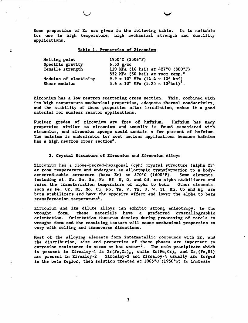
Some properties of Zr are given in the following table. It is suitablefor use in high temperature, high mechanical strength and ductilityapplications.
Table 1. Properties of Zirconium
Melting point 1930-C (3506-F)Specific gravity 6.53 g/ccTensile strength 110 MPa (16 ksi) at 427'C (800'F)
552 Pa (80 ksi) at room temp.9
Modulus of elasticity 9.9 x 10⁴ MPa (14.4 x 10³ ksi)Shear modulus 3.6 x 10⁴ MPa (5.25 x 10³ksi)7.
Zirconium has a low neutron scattering cross section. This, combined withits high temperature mechanical properties, adequate thermal conductivity,and the stability of these properties after irradiation, makes it a goodmaterial for nuclear reactor applications.
Nuclear grades of zirconium are free of hafnium. Hafnium has manyproperties similar to zirconium and usually is found associated withzirconium, and zirconium sponge could contain a few percent of hafnium.The hafnium is undesirable for most nuclear applications because hafniumhas a high neutron cross section8.
3. Crystal Structure of Zirconium and Zirconium Alloys
Zirconium has a close-packed-hexagonal (cph) crystal structure (alpha Zr)at room temperature and undergoes an allotropic transformation to a body-centered-cubic structure (beta Zr) at 870'C (1600'F). Some elements,including Al, Sb, Sn, Be, Pb, Hf, N, 0, and Cd, are alpha stabilizers andraise the transformation temperature of alpha to beta. Other elements,such as Fe, Cr, Ni, Mo, Cu, Nb, Ta, V, Th, U, W, Ti, Mn, Co and Ag, arebeta stabilizers and have the opposite effect and lower the alpha to betatransformation temperatures.
Zirconium and its dilute alloys can exhibit strong anisotropy. In thewrought form, these materials have a preferred crystallographicorientation. Orientation textures develop during processing of metals towrought form and the resulting texture will cause mechanical properties tovary with rolling and transverse directions.
Most of the alloying elements form intermetallic compounds with Zr, andthe distribution, size and properties of these phases are important tocorrosion resistance in steam or hot water1 . The main precipitate whichis present in Zircaloy-4 is Zr(Fe,Cr)2, while Zr(Fe,Cr)2 and Zr2(Fe,Ni)are present in Zircaloy-2. Zircaloy-2 and Zircaloy-4 usually are forgedin the beta region, then solution treated at 1065'C (1950'F) to increase
3
the amount of alloying elements going into solid solution, and this isfollowed by a water quench. The uniform distribution of fineintermetallic compounds produced by heat treating and quenching, ispreserved by hot working in the alpha region below 790OC (1472°F)8 .
B. Zircaloy
1.General Information
Zircaloy-2 and Zircaloy-4 were developed for the nuclear industry, and areused as fuel cladding in power boilers. Both alloys are more than ninetyeight percent Zr.
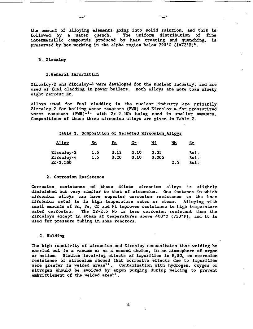
Alloys used for fuel cladding in the nuclear industry are primarilyZircaloy-2 for boiling water reactors (BWR) and Zircaloy-4 for pressurizedwater reactors (PWR)11' with Zr-2.5Nb being used in smaller amounts.Compositions of these three zirconium alloys are given in Table 2.
Table 2. Composition of Selected Zirconium Alloys
Alloy in e Cr Ri Nb Zr
Zircaloy-2 1.5 0.12 0.10 0.05 Bal.Zircaloy-4 1.5 0.20 0.10 0.005 Bal.Zr-2.5Nb 2.5 Bal.
2. Corrosion Resistance
Corrosion resistance of these dilute zirconium alloys is slightlydiminished but very similar to that of zirconium. One instance in whichzirconium alloys can have superior corrosion resistance to the basezirconium metal is in high temperature water or steam. Alloying withsmall amounts of Sn, Fe, Cr and Ni improves resistance to high temperaturewater corrosion. The Zr-2.5 Nb is less corrosion resistant than theZircaloys except in steam at temperatures above 400'C (750'F), and it isused for pressure tubing in some reactors.
C. Welding
The high reactivity of zirconium and Zircaloy necessitates that welding becarried out in a vacuum or as a second choice, in an atmosphere of argonor helium. Studies involving effects of impurities in HSOA on corrosionresistance of zirconium showed that corrosive effects due to impuritieswere greater in welded areas12. Contamination with hydrogen, oxygen ornitrogen should be avoided by argon purging during welding to preventembrittlement of the welded area 1 3 .
4
III. REPOSITORY ENVIRONMENT
The repository environments for locations involving basalt, salt and tuffwere reviewed previously14 and conditions were given in some detail. Someof the information from this reference relating to the tuff repository ispresented here. The tuff repository is located in the state of Nevada andis in the Topopah Spring Member of the Paintbrush Tuff at Yucca Mountain.The tuff is in unsaturated devitrified zones with twelve percent porosityand contains five volume percent water14 * . Oxygen is expected to bepresent. Water flow has been stated to be 6 to 8 mm per year, but thiscould change.
Radiation present will be gamma and will be approximately 10 rads perhour. This repository probably will not pressurize after closing, and thewater will boil off leaving a residue of salts which may or may notredissolve.
Water taken from the Jackass Flats J-13 Well in the tuff repository areacontains a number of ions in sall concentrations including Li+, Na+, K+,Mg 2 , Ca+2, Sr+2, Ba'2, Be, Al+3, 5i02. F, C, C03 2, HCO3 , S04-2,NO3-, P04 3' The pH of the water has been reported to be 7.1 but could gomore basic depending on the ion concentration. The water pH could shiftto the acidic range due to radiolysis of N/0 2/H20 mixtures. Analyticalwork still is needed to show whether pore water in the tuff has the samecomposition as the J-13 water.
Calculations of repository temperatures over extended times involve agiven repository design and assumptions used, such as the absence ofpacking material, and are subject to change. Calculated temperatureversus time profiles for a tuff repository are given in reference 14 andshow a fuel centerline temperature of 330'C which decreases to 100°C after300 years. Some other calculations showed that centerline temperatureswere in excess of 350C'5 - The calculated temperature at the canister wasapproximately 245°C and decreased to 80'C after 200 years.
IV. TYPES OF CORROSION
Corrosion processes within the tubing due to reactions of the claddingwith the nuclear fuel and its environment must be considered as well ascorrosion behavior of the outer surface of the cladding which is exposedto environments of reactor service, temporary storage and permanentstorage. Most cladding failures reported until now appear to haveinitiated at the inner tubing wall. Causes of these failures include cladcollapsing, pellet cladding interactions, hydriding, fretting and somefailures due to unknown causes. The problem of collapsing was correctedby pressurizing the clad fuel. Causes of failure on the outside of thecladding include water side corrosion and crud-induced localizedcorrosion. A discussion of the forms of corrosion and the corrosionbehavior of zirconium in various media are given in references 7 and 8.Discussions of Zircaloy cladding corrosion under repository typeconditions and effects on radionuclide containment are given in reference14. Selected information on corrosion behavior is given in the followingsections.
5
A. General Corrosion
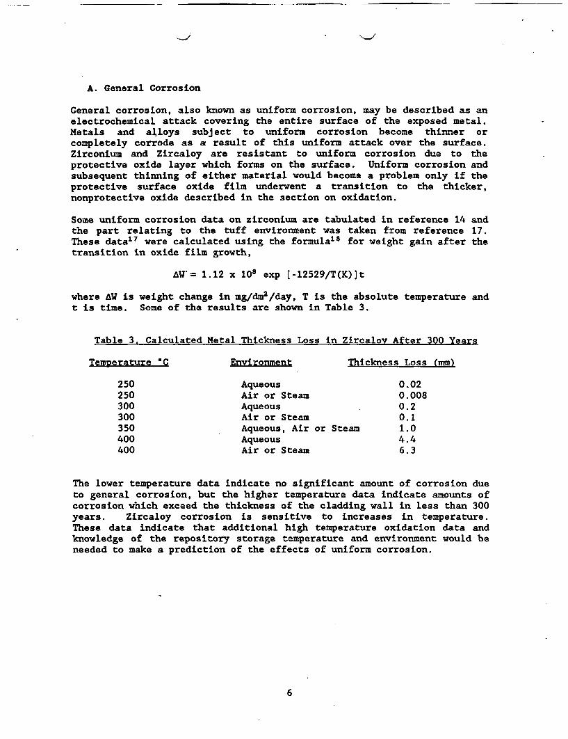
General corrosion, also known as uniform corrosion, may be described as anelectrochemical attack covering the entire surface of the exposed metal.Metals and alloys subject to uniform corrosion become thinner orcompletely corrode as a result of this uniform attack over the surface.Zirconium and Zircaloy are resistant to uniform corrosion due to theprotective oxide layer which forms on the surface. Uniform corrosion andsubsequent thinning of either material would become a problem only if theprotective surface oxide film underwent a transition to the thicker,nonprotective oxide described in the section on oxidation.
Some uniform corrosion data on zirconium are tabulated in reference 14 andthe part relating to the tuff environment was taken from reference 17.These data17 were calculated using the formula'8 for weight gain after thetransition in oxide film growth,
AW.= 1.12 x 10⁸ exp [-12529/T(K)]t
where W is weight change in mg/dm2/day, T is the absolute temperature andt is time. Some of the results are shown in Table 3.
Table 3. Calculated Metal Thickness Loss in Zircaloy After 300 Years
Temperature C Environment Thickness Loss (mm)
250 Aqueous 0.02250 Air or Steam 0.008300 Aqueous 0.2300 Air or Steam 0.1350 Aqueous, Air or Steam 1.0400 Aqueous 4.4400 Air or Steam 6.3
The lower temperature data indicate no significant amount of corrosion dueto general corrosion, but the higher temperature data indicate amounts ofcorrosion which exceed the thickness of the cladding wall in less than 300years. Zircaloy corrosion is sensitive to increases in temperature.These data indicate that additional high temperature oxidation data andknowledge of the repository storage temperature and environment would beneeded to make a prediction of the effects of uniform corrosion.
6
B. Stress Corrosion Cracking
Stress corrosion cracking (SCC) is a complex form f localized corrosionthat occurs in the presence of a corroding environment and a tensilestress. SCC can occur without warning and can be catastrophic. SCC isdiscussed in reference 19. Factors important in determining mechanisms ofSCC include chemical composition, electrochemical reactions, mechanicalproperties and condition of the material. Anodic dissolution at the cracktip and a concentrated stress at the crack tip can lead to failure.Adsorption of ionic species in the strained area of the crack tip can alsolead to failure. Some SCC failures appear to result from a series ofbrittle fractures. There are other mechanisms, related to these, whichcan lead to SCC failure. The U-bend test, consisting of a rectangularspecimen bent around a predetermined radius and maintained under constantstrain during corrosion exposure, or other similar tests can be applied todetermine whether a metal undergoes SCC, but since SCC can develop overtime without showing indications of this problem, the absence of SCCfailure does not mean that the material is immuneI 3 . Metals which.aresusceptible to SCC can appear sound for extended times can fail suddenlydue to SCC. Additional information on a materials susceptibility to SCCcan be obtained from slow strain rate testing.
Zirconium and its alloys are resistant to SCC in seawater, most aqueousenvironments and some sulfate and nitrate solutions. SCC of Zircaloy canoccur in concentrated methanol, solutions containing heavy metalchlorides, ferric chloride solutions, copper chloride solutions, organicsolutions with chloride, gaseous iodine or fused salts. Liquid metalembrittlement has been reported for zirconium in contact with moltencesium and with liquid sodium or cadmiuml5'20 .2 1.
Data show that if the electrode potential of Zircaloy-2 is raised to avalue which is slightly more positive than its corrosion potential inneutral dilute sodium chloride solutions at 25'C, SCC will occur22. SCCfrom the fuel side of the cladding can result from effects of fissionproducts such as iodides2 l ,23.
The estimated in-reactor failure rate for LWR fuel cladding is 0.01percent2 4. Earlier in-reactor failure rates in BWRs were as high as onepercent. Less than 0.002 percent of Zircaloy fuel rod failures, underreactor conditions, are caused by waterside corrosion15 ,17 * During in-reactor service, there is some creepdown of the cladding and alsoexpansion of the fuel occurs causing localized stress regions in thecladding.
The hoop stress, s, defined as s = pr/t, where p is pressure in MPa, r isthe radius of the tube in meters and t is' the wall thickness of the tubein meters, can be an important factor in failures initiating from theinside of the cladding. The importance of the hoop stress increases whenthe ratio of the tube diameter to the tube wall thickness is greater by afactor of ten. Approximate measurements for Zircaloy-2 and Zircaloy-4 arean outside diameter of 12 mm with a wall thickness of 0.9 mm and anoutside diameter of 11 mm and a wall thickness of 0.9, respectively.
7
-
Calculations of the minimum hoop stress necessary for SCC due to iodinegave values of 200-220 MPa at 400OC2 1 and 216 Pa at 300°C25 .26. Hoopstresses in rods stored below 6C have been estimated to be in the rangeof 1.7 MPa to 3.7 MPa with some having a hoop stress of 5.4 MPa2 7,14 . Inlate 1978, General Electric began He pressurizing BWR fuel rods to O.3MPa,and Westinghouse began He pressurizing PWR fuel rods to 3 or 3.4 Pal&The estimate then for the hoop stress in a BR rod was 3.1 MPa at 100'Cand 9.2 MPa for a PWR fuel rod2 8'l.
Calculations of the hoop stress during the containment period at 300'Cresult in approximately 22.7 for BWR rods and 82.5 for PWR rodsl4.17
These hoop stresses are much lower than the 200 - 220 MPa described asnecessary to produce SCC, but the total considerations regarding whetherSCC from inside the cladding will occur must also include inner tube wallsurface defects, local stresses, texture of the inner surface, localizedchemical inhomogeneities either in or on the surface, whether hydridinghas occurred and whether the fuel rod was pressurized. Inner surfacetexture can affect susceptibility to SCC29' and this effect can be reducedby modifying the texture30.
C. Effects of Hydrogen
Failures due to hydrogen pick-up by a material are due to the combinationof the embrittling effects caused by hydride formation or hydrogenadsorption and the presence of stress. Other factors such as temperatureand chemical environment also play a role in this type of failure.Hydrogen embrittlement failures have an induction period as does SCC andcrack propagation is similar in hydrogen embrittlement and SCC. Crackinitiation mechanisms for SCC and hydrogen embrittlement are different,and cathodic protection methods which can be applied to prevent or delaySCC can be sources of hydrogen and are not appropriate for use againsthydrogen embrittlement.
Zircaloy-2 is somewhat more subject to hydrogen pick-up than is Zircaloy-4. Examples of cladding failures attributed to hydrogen adsorption fromhydrogen produced during corrosion have been reported28. An earliersource of hydrogen was water left in the fuel inside of the cladding, butthis was eliminated by drying the fuel.
The solubility of hydrogen in Zircaloys is approximately 60 ppm at 300'Cand is 1 ppm at 20'C1 5.33,34. 35. Exceeding this solubility will result inthe formation of brittle hydrides. The hydrogen content of spent fuelcladdings has been reported to be in a range of 80 to 150 ppm and alsoless than 50 ppm33. Sources of hydrogen available to the cladding includehydrogen generation by corrosion processes, hydrogen present in thereactor cooling water and other possible sources. A general or uniformcorrosion rate in excess of 3 mils (0.003 in. or 0.076 mm) per year wouldresult in embrittlement except in oxidizing environments1 3"
8
D. Pitting
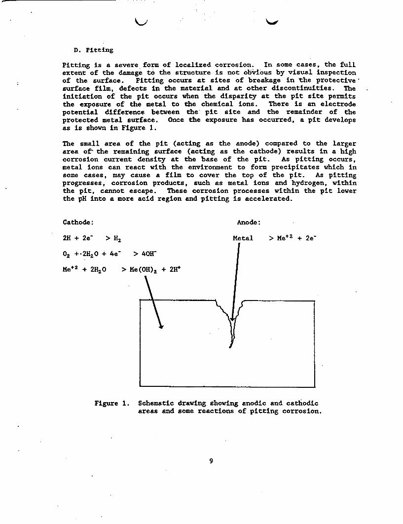
Pitting is a severe form of localized corrosion. In some cases, the fullextent of the damage to the structure is not obvious by visual inspectionof the surface. Pitting occurs at sites of breakage in the protectivesurface film, defects in the material and at other discontinuities. Theinitiation of the pit occurs when the disparity at the pit site permitsthe exposure of the metal to the chemical ions. There is an electrodepotential difference between the pit site and the remainder of theprotected metal surface. Once the exposure has occurred, a pit developsas is shown in Figure 1.
The small area of the pit (acting as the anode) compared to the largerarea o the remaining surface (acting as the cathode) results in a highcorrosion current density at the base of the pit. As pitting occurs,metal ions can react with the environment to form precipitates which insome cases, may cause a film to cover the top of the pit. As pittingprogresses, corrosion products, such as metal ions and hydrogen, withinthe pit, cannot escape. These corrosion processes within the pit lowerthe pH into a more acid region and pitting is accelerated.
Cathode: Anode:
2H + 2e > H2
02 +2H20 + 4e-
Me+2 + 2H20
Metal > Me+2 + 2e-
Figure 1. Schematic drawing showing anodic and cathodicareas and some reactions of pitting corrosion.
9
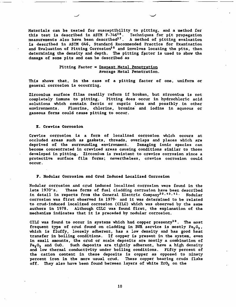
Materials can be tested for susceptibility to pitting, and a method forthis test is described in ASTM F-7463 6 . Techniques for pit propagationmeasurements also have been described37. A method of pitting evaluationis described in ASTM G46, Standard Recommended Practice for Examinationand Evaluation of Pitting Corrosion38 and involves locating the pits, thendetermining the density and depth. The pitting factor is used to show thedamage of some pits and can be described as
Pitting Factor = Deepest Metal PenetrationAverage Metal Penetration.
This shows that, in the case of a pitting factor of one, uniform orgeneral corrosion is occurring.
Zirconium surface films readily reform if broken, but zirconium is notcompletely immune to pitting. Pitting does occur in hydrochloric acidsolutions which contain ferric or cupric ions and possibly in otherenvironments. Fluorine, chlorine, bromine and iodine in aqueous orgaseous forms could cause pitting to occur.
E. Crevice Corrosion
Crevice corrosion is a form of localized corrosion which occurs atoccluded areas such as gaskets, threads, overlaps and places which aredeprived of the surrounding environment. Damaging ionic species canbecome concentrated in creviced areas causing conditions similar to thosedeveloped in pitting. Zirconium is resistant to crevice corrosion since aprotective surface film forms; nevertheless, crevice corrosion couldoccur.
F. Nodular Corrosion and Crud Induced Localized Corrosion
Nodular corrosion and crud induced localized corrosion were found in thelate 1970's. These forms of fuel cladding corrosion have been describedin detail in reports from the General Electric Company39 .40-41 Nodularcorrosion was first observed in 1979 and it was determined to be relatedto crud-induced localized corrosion (CILC) which was observed by the sameauthors in 1978. Although CILC was found first, the explanation of themechanism indicates that it is preceded by nodular corrosion.
CILC was found to occur in systems which had copper presenty39. The mostfrequent type of crud found on cladding in BWR service is mostly Fe203,which is fluffy, loosely adherent, has a low density and has good heattransfer in boiling conditions. If copper is present in the system, evenin small amounts, the crud or scale deposits are mostly a combination ofFe203 and CuO. Such deposits are tightly adherent, have a high densityand low thermal conductivity under boiling conditions. Fifty percent ofthe cation content in these deposits is copper as opposed to ninetypercent iron in the more usual crud. These copper bearing cruds flakeoff. They also have been found between layers of white ZrO2 on the
10
cladding surface. The protective form of ZrO2 is black and covers thesurface as a thin layer. Reactions of the oxide with copper result insevere local corrosion or pits in the regions 20 to 40 inches andoccasionally at 80 to 100 inches from the lower end of the fuel rod. CILCfailures are associated with soluble copper in the water which could comefrom corrosion or wear of tubing or other parts containing copper. CILCfailures occur more frequently in (U,Gd)02 rods but failure can occur inU02 rods. The power exposure threshold must be sufficient to produce fuelfailure. These failures occur in only a small fraction of the rods.
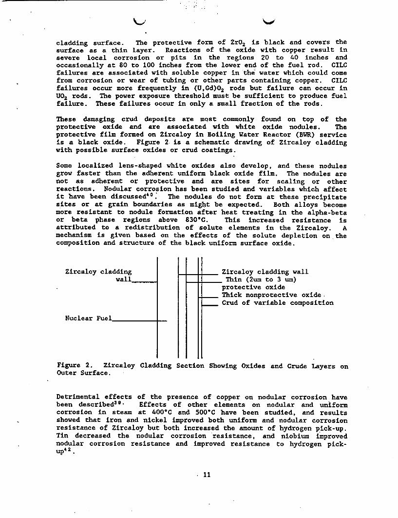
These damaging crud deposits are most commonly found on top of theprotective oxide and are associated with white oxide nodules. Theprotective film formed on Zircaloy in Boiling Water Reactor (BWR) serviceis a black oxide. Figure 2 is a schematic drawing of Zircaloy claddingwith possible surface oxides or crud coatings.
Some localized lens-shaped white oxides also develop, and these nodulesgrow faster than the adherent uniform black oxide film. The nodules arenot as adherent or protective and are sites for scaling or otherreactions. Nodular corrosion has been studied and variables which affectit have been discussed40. The nodules do not form at these precipitatesites or at grain boundaries as might be expected. Both alloys becomemore resistant to nodule formation after heat treating in the alpha-betaor beta phase regions above 830'C. This increased resistance isattributed to a redistribution of solute elements in the Zircaloy. Amechanism is given based on the effects of the solute depletion on thecomposition and structure of the black uniform surface oxide.
Zircaloy cladding Zircaloy cladding wallwall . Thin (2um to 3 um)
protective oxideThick nonprotective oxideCrud of variable composition
Nuclear Fuel _ __
Figure 2. Zircaloy Cladding Section Showing Oxides and Crude Layers onOuter Surface.
Detrimental effects of the presence of copper on nodular corrosion havebeen described3 9 Effects of other elements on nodular and uniformcorrosion in steam at 400'C and 500'C have been studied, and resultsshowed that iron and nickel improved both uniform and nodular corrosionresistance of Zircaloy but both increased the amount of hydrogen pick-up.Tin decreased the nodular corrosion resistance, and niobium improvednodular corrosion resistance and improved resistance to hydrogen pick-up 4 2
. 11
-
V. OXIDATION OF ZIRCONIUM
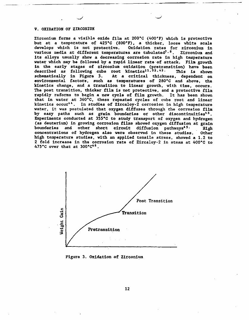
Zirconium forms a visible oxide film at 200'C (4001F) which is protectivebut at a temperature of 425iC (800@F), a thicker, loose white scaledevelops which is not protective. Oxidation rates for zirconium invarious media at different temperatures are tabulated7'8. Zirconium andits alloys usually show a decreasing corrosion rate in high temperaturewater which may be followed by a rapid linear rate of attack. Film growthin the early stages of zirconium oxidation (pretransition) have beendescribed as following cube root kineticsll.32, 3 . This is shownschematically in Figure 3. At a critical thickness, dependent onenvironmental factors, such as temperatures of 280-C and above, thekinetics change, and a transition to linear growth, with time, occurs.The post transition, thicker film is not protective, and a protective filmrapidly reforms to begin a new cycle of film growth. It has been shownthat in water at 360-C, these repeated cycles of cube root and linearkinetics occur . In studies of Zircaloy-2 corrosion in high temperaturewater, it was postulated that oxygen diffuses through the corrosion filmby easy paths such as grain boundaries or other discontinuities45.Experiments conducted at 355-C to study transport of oxygen and hydrogen(as deuterium) in growing corrosion films showed oxygen diffusion at grainboundaries and other short circuit diffusion pathways45. Highconcentrations of hydrogen also were observed in these studies. Otherhigh temperature studies, with an applied tensile stress, showed a 1.2 to2 fold increase in the corrosion rate of Zircaloy-2 in steam at 400-C to475'C over that at 3006C46.
Post Transition
Transition
Pretransition:3/
Figure 3. Oxidation of Zirconium
12
The oxidation rate in the pretransition region is enhanced by reactorradiation and is related to the fast neutron flux47. Pretransitionoxidation curves for zirconium in water or steam, fused salt or air at350'C are essentially the samell. The structure of the initial oxide filmin terms of grain boundaries and other defects appears to be important inthe further oxidation or growth of.the oxide film.
Calculations based on weight gain at -a temperature of 180'C for 10,000years show depths of oxidized Zircaloy ranging from 4 pm to 53 pm, and itwas concluded that at this temperature and below, failure of the Zircaloydue to oxidation should not occur32. Results of other corrosion testsbased on oxidation and weight gain are given in reference 14. Some ofthese data indicate that the cladding would fail. If the watertemperature is below about 250'C when the water reaches the Zircaloycladding, the oxidation mechanism could change and the rate could becomeconsiderably lower as is indicated in the post transition region of Figure3.
Information on the condition of spent fuel and spent fuel cladding isavailable from reports developed by the Materials Characterization Center(MCC). The Approved Testing Material (ATM) - 10648 is a high burn-up,high fission gas release material from a PWR and is one of five ATMs whichare representative of different fuel types and reactor conditions.Metallographic characterization indicated that the oxide layer or reactionproduct on the interior surface of the cladding was uniform and ranged inthickness from 4 pm (0.004 mm) to 9 m (0.009 mm). The exterior claddingsurface oxide was thicker in the middle of the rod than at the bottom ofthe rod. The top of the rod was not analyzed. The exterior oxide in themiddle of the rod has a thickness ranging from 11 m (0.011 mm) to 15 pm0.015 mm) and was multilayered with the outside layer being loosely held.Further microstructural analysis indicated that increased hydriding couldbe correlated with increased cladding oxide thickness. Not all spent fuelhas a uniform surface oxide, and ATM-103, representing a moderate burn-up,low fission gas release, material had localized corrosion products withthe remaining surface relatively bare.
VI. AQUEOUS CORROSION RESISTANCE OF ZIRCONIUM/ZIRCALOY
Zirconium readily oxidizes to form a protective surface film and isresistant to strong acids, alkalis and to organic acids. Carbon andnitrogen impurity contents of 40 and 300 ppm, respectively, increase thecorrosion rate of zirconium. Zircaloy-2 has less than 0.006 percentnitrogen. The addition of tin to Zirconium counteracts detrimentaleffects of absorbed gas on corrosion resistance7 ,8.
Zirconium is attacked by fluoride ions, wet chlorine, aqua regia,concentrated sulfuric acid, hydrofluoric acid, ferric chloride and cupricchloride. An extensive table showing corrosion rates of zirconium invarious media is given in reference 7 which indicated that the informationshould be used only as a guide and that further tests, in situ, should beconducted to verify the corrosion resistance in a given medium. A table,
13
showing corrosion rates in various media, is included in reference 7.Much of the information on reactions in acids and alkalies is taken fromreferences 7 and 8, but it is verified in numerous other references.
A. Sulfuric Acid
Zirconium is corrosion resistant in sulfuric acid in concentrations up to60% up to boiling temperatures, and concentrations of 80% at roomtemperature. This resistance is lower for welded material and heataffected zones even at lower acid concentrations. This resistance is theresult of a protective cubic ZrO2 film with a small amount of a monocliniczirconium oxide phase present7. Corrosion resistance in concentrations ofsulfuric acid above 70% is strongly temperature dependent and is affectedby the formation of a looser less protective film, Zr(SO4)2.4H20 and alsothe formation of hydrides. These films, consisting of zirconium sulfate,zirconium hydrides and small zirconium metal particles, can be pyrophoric.Impurities in the sulfuric acid such as Fe+2, Cu+2, Cl-, N3- andseawater, have detrimental effects on Zircaloy corrosion resistance tosulfuric acid1 2 .
B. Nitric Acid
Zirconium is resistant to nitric acid in concentrations up to 65 wt.percent and at a stress limit of 150 MPa up to temperatures of 120C 4 9 .Other studies50' 51 showed high corrosion resistance for zirconium in 70percent nitric acid at room temperature and little effect on the SCCsusceptibility by the presence of FeCI3, seawater, NaCl and corrosionproducts released from stainless steel. Fluoride ions should be avoidedand chlorine in the gaseous phase should be avoided as well as highstresses at elevated temperatures in 70 percent HNO3.
C. Hydrochloric Acid, HCl; Phosphoric Acid, H3PO4; Alkalies; SalineSolutions
Zirconium is resistant to all concentrations of hydrochloric acid totemperatures above boiling. Zirconium is resistant to phosphoric acid atconcentrations up to 55 percent and at temperatures above boiling.Zirconium is resistant to alkalies. It is resistant to saline solutionsto temperatures of boiling except for solutions containing FeCl3 andCuCl 2 .
D. Water and Steam
Corrosion resistance of Zircaloy-2 and Zircaloy-4 in high temperaturewater and steam is superior to that of unalloyed zirconium. Corrosionresistance of Zr-2.5Nb is generally less than that of the Zircaloys but insteam, at temperatures in excess of 4000C (750 F), Zr-2.5Nb has superiorcorrosion resistance. The corrosion resistance of Zr-2.5 Nb can beimproved by heat treating.
14
VII. SUMMARY
Zirconium is a reactive metal which becomes highly corrosion resistant tovarious media due to the formation of a protective surface oxide film.Low alloy zirconium alloys, such as Zircaloy-2 and Zircaloy-4 which areused for nuclear fuel cladding, essentially maintain this corrosionresistance under specified conditions. Zircaloys-2 and 4 are resistant,within limits, to acids, alkalies and organic acids. Corrosion ofZircaloys in water and steam is increased with temperature and with carbonand nitrogen impurity contents. Zirconium is not corrosion resistant tofluoride ions, wet chlorine, aqua regia, concentrated acids and ferricchloride and cupric chloride.
Additional electrochemical and corrosion data are needed for predictingZircaloy corrosion behavior in a long term nuclear waste repository.Temperatures may range from 330'C to 100'C for the first 300 years, andgeneral corrosion might not be a problem under these conditions. However;additional information on mechanisms of oxidation and passivity, alongwith effects of ions present and other environmental factors, would beuseful for relating to the occurrence of localized corrosion.
Zircaloy may be subject to stress corrosion cracking initiating from theinside of the cladding or from the outside of the cladding. Hydrogenembrittlement and metal embrittlement may occur, and there is possibilityof pitting occurring. Ions such as those of the halides, especiallyiodine, would be suspect for causing SCC. Ions such as those of copper oriron may react with the surface oxide film and eliminate the film'sprotection at a local site. The literature contains many references ofresearch carried out to address these localized corrosion problems inreactor service. Research is needed now to address conditions of nuclearwaste storage, including environmental and material variations which couldoccur over time.
The oxidation rate in the pretransition region of oxide film formation onZircaloy is increased by radiation. Existing data need to be coordinatedand more data are needed to determine effects of radiation and temperatureon the oxide thickness and transition temperature.
Metallurgical conditions of the cladding including orientation textures,defects, impurities and histories in reactor service and storage should beestablished and catalogued. These factors, also, will affect thecorrosion and durability of the cladding.
Solubility of the spent fuel will be a factor in the amount and type ofradionuclides released, and oxidized fuel has increased aqueoussolubility. Oxidation of the spent fuel could occur at rates greater thanthose previously predicted. This increased oxidation could be due to alower activation energy for oxygen diffusion at grain boundaries in thespent fuel. Spent fuel volume expansion resulting from oxidation couldcause stress cracks in the Zircaloy cladding.
15
VIII. RECOMMENDATIONS
Aspects of Zircaloy corrosion which need further study include the effectsof repository conditions on the following topics:
1. Structure of the oxide film, its stability and transition, and howthis film and, also passivity, are affected by temperatures, wetting,drying and other conditions of the repository
2. Stress corrosion cracking and other mechanical and corrosionfailures in which surface crystallographic texture has an importantrole
3. Susceptibility of Zircaloy to stress corrosion cracking usingvarious tests including slow strain rate or other appropriatemeasurements.
4. Susceptibility to pitting or other localized corrosion inenvironments containing ferric chloride, cupric chloride, fluorineand under conditions of varying pH
5. Welding integrity and localized and general corrosion of weldedareas
6. Effects of previous service history, especially relating tohydrogen uptake and hydrogen embrittlement cracking and otherlocalized corrosion
7. Projected stability of initial condition of cladding at time ofrepository storage using data obtained from characterization of spentfuel approved testing materials (ATMs).
IX. REFERENCES
1. Title 40 Code of Federal Regulations (CFR), Part 191- EnvironmentalRadiation Protection Standards for Management and Disposal of SpentNuclear Fuel, High-Level and Transuranic Radioactive Wastes, United StatesEnvironmental Protection Agency, 1987.
2. Title 10 CFR Part 60-Disposal of High-Level Radioactive Wastes inGeologic Repositories: Section 60.113(a)(1)(ii)(B), United States NuclearRegulatory Commission, 1988.
3. Title 10 CFR Part 960-General Guidelines for the Recommendation ofSites for Nuclear Waste Repositories, United States Department of Energy,1988.
4. Braithwaite, J. W., Corrosion of Containment Materials for Radioactive-Waste Isolation, Am. Soc. for Metals Handbook, Ninth Ed. Vol. 13, 1987,pp. 971-984.
16
5. Wilson, C. N. and V. M. versby, V. ., UCRL-91464, RadionuclideRelease from PWR Fuels in a Reference Tuff Repository Groundwater,Lawrence Livermore National Laboratory, 1985.
6. Encyclopedia Britannica, Zirconium, Vol. 23, Wm. Benton, Pub., 1973.
7. Yau, T. L. and Webster, R. T., Corrosion of Zirconium and Hafnium, Am.Soc. for Metals Handbook, Ninth Ed., Vol. 13, 707-721, 1987.
8. Schemel, John H., Introduction to Zirconium and Its Alloys, andCorrosion Resistance of Zirconium and Its Alloys, Am. Soc. for MetalsHandbook, Ninth Ed., Vol. 3, 781-791, 1980.
9. Fontana, M. G. and Greene, N. D., Corrosion Engineering, McGraw-HillSeries in Materials Science and Engineering,McGraw-Hill Book Co., NewYork, 2nd Ed., 179-180, 389, 1978.
10. Berry, Warren, Corrosion in Nuclear Applications, John Wiley and Sons,Inc., New York, 1971.
11. Cox, B., Oxidation of Zirconium and Its Alloys, Advances in CorrosionScience and Technology, 5, M. G. Fontana and R. W. Staehle, Eds., PlenumPress, 173-391, 1976.
12. Yau, Te-Lin, (Teledyne Wah Chang Albany, Albany, OR 97321) Effects ofImpurities in Sulfuric Acid on the Corrosion Resistance of Zirconium.Industrial Applications of Titanium and Zirconium, Third, Conf., ASTM STP830, R. T. Webster and C. S. Young, Eds., Am. Soc. for Testing andMaterials, 203-211, 1984.
13. Moniz. B. J., Corrosion Resistance of Zirconium in Chemical ProcessingEquipment, Industrial Applications of Titanium and Zirconium, ASTM STP830, R. T. Webster and C. S. Young, Eds. American Soc. for Testing andMaterials, 190-202, 1984.
14. Soo, P. and Gauss, E., Review of DOE Waste Package Program, NUREG/CR-2482, Vol. 7, 1985.
15. McCright, R. D., and others, UCRL-89988, Selection of CandidateCanister Materials for High-Level Nuclear Waste Containment in a TuffRepository, Lawrence Livermore National Laboratory, 1983.
16. Hockman, J. N. and O'Neal, W. C., Thermal Modeling of Nuclear Waste inTuff, paper presented at the ANS/ASME WASTE MANAGEMENT '84 Meeting,Tuscon, Arizona, March 11-15, 1984.
17. Woodley, R. E., The Characteristics of Spent LWR Fuel Relevant to ItsStorage in Geologic Repositories, HEDL-TME, 83-28, Hanford EngineeringDevelopment Laboratory, 1983.
18. Hillner, S., Corrosion of Zirconium Based Alloys - An Overview ofZirconium in the Nuclear Industry, ASTM STP 633, American Soc. forTesting and Materials, 211-235, 1977.
17
19. R. H. Jones and R. E. Ricker, Stress Corrosion Cracking, Am. Soc. forMetals Handbook, Ninth Ed., Vol. 3, 145-163, 1987.
20. Syrett, B. C., Cubiciotti, D. and Jones, R. L., Embrittlement ofZircaloy-4 by Liquid Cesium at 300 C, Zirconium in the Nuclear Industry,ASTM STP 633, A. L. Lowe, Jr and G. W. Parry, Eds., American Society forTesting and Materials, 281-294, 1977.
21. Shann, S. H.- and Olander, D. R., Stress Corrosion Cracking of Zircaloyby Cadmium, Iodine, and Metal Iodides, J. Nuc. Mater., Vol. 113, No. 2-3,234-248, 1983.
22. Cox, B., Stress Corrosion Cracking of Zircaloy-2 in Neutral AqueousChloride Solutions at 25 C, Corrosion, Vol. 29, No.4, 157-166, 1973.
23. Syrett, B. C., Cubiciotti, D., and R. L. Jones, Effects of Texture andSurface Condition on the Iodine Stress Corrosion Cracking Susceptibilityof Unirradiated Zircaloy-2, Nuc. Technology, Vol. 55, No. 3, 628-641,1981.
24. Nishimura, S., Evaluation of Crack Growth Rate and Variation ofInitiation Time for Stress Corrosion Cracking in Zircaloy-2 Cladding Tube,Am. Nuc. Soc. Meeting, New Orleans, Louisiana, June, 1984.
25. Wood, J. C., Factors Affecting Stress Corrosion Cracking of Zircaloyin Iodine Vapor, J. Nuc. Mater., Vol. 45, 105-122, 1972/73.
26. Wood, J. C. and Kelm, J. R., Effects of Irradiation on the Iodine-Induced Stress Corrosion Cracking of CANDU Zircaloy Furl Cladding, Mater.Sci., Vol. 8, No. 3, 127-161, 1983.
27. Hahn, C. R. and Wilson, C. L., Appendix to BNWL-2256, Behavior ofSpent fuel in Water Pool Storage, A. B. Johnson, Jr., Pacific NorthwestLab., Sept, 1977.
28. Jenks, G. H., Effects of Gaseous Radioactive Nuclides on the Designand Operation of Repositories for Spent LWR Fuel in Rock Salt, ORNL-5578,Oak Ridge National Lab., Dec., 1979.
29. Knorr, D. B. and Pellous, R. M., Effects of Texture and Microstructureon the Propagation of Iodine Stress Corrosion Cracks in Zircaloy, Met.Trans. A Vol. 13A, 73-83, 1982.
30. Smith, E., Effect of Inner Surface Texture on the Stress CorrosionCracking Susceptibility of Zircaloy Cladding, J. of Nuc. Mater., Vol. 89,No. 1, 87-91, 1980.
31. Mcleish, J. A., Review of the Corrosion Resistance and HydrogenAdsorption f Zircaloy-2, Metallurgical Journal, Univ. of Strathclyde,Glascow, No. 19, 34-41, 1969.
32. Rothman, A. J., Potential Corrosion and Degradation Mechanisms pfZircaloy Cladding on Spent Nuclear Fuel in a Tuff Repository, Attachment10 to MRB-0418, JUCID-20172, Contract W-7405-Eng-48, Lawrence LivermoreNational Laboratory, Livermore, CA 94550, 1984.
18
33. Sawatzky, A. and Wilkins, B. J. S., Hydrogen Solubility in ZirconiumAlloys Determined by Diffusion, J. Nuc. Mater., Vol. 22, 304, 1967.
34. Simpson, L. A. and Cann, C. D., Fracture Toughness of ZirconiumHydride and Its Influence on the Crack Resistance of Zirconium Alloys, J.Nuc. Mater., Vol. 87, 303-316, 1979.
35. Simpson , L. A. and Puls, . P., The Effects of Stress, Temperatureand Hydrogen Content on Hydride-Induced Crack Growth in Zr-2.5 Pt Nb,Met. Trans., Vol. bOA, 1093, 1979.
36. Standard Test Method for Pitting or Crevice Corrosion of MetallicSurgical Implant Materials, F746, Annual Book of ASTM Standards, AmericanSociety for Testing and Materials, Philadelphia, PA.
37. Syrett, B. C., Pit Propagation Rate Curves for Assessing PittingResistance, Corrosion, Vol. 33, 221, 1977.
38. Standard Recommended Practice for Examination and Evaluation ofPitting Corrosion, ASTM G46, Annual Book of ASTM STandards, AmericanSociety for Testing and Materials, Philadelphia, PA.
39. Marlowe, M. O., Armijo, J. S., Cheng, B. and Adamson, R. B.,Nuclear Fuel Cladding Localized Corrosion, Am. Nuc. Soc. Topical Meetingon Light Water Reactor Fuel Performance, Orlando, Florida, April 21-24,1985.
40. Cheng, B., Levin, H. A., Adamson, R. B., Marlowe, M. O., and Monroe,V. L., Development of a Sensitive and Reproducible Steam Test for ZircaloyNodular Corrosion, Am. Soc. for Testing and Materials 7th Internatl. Conf.on Zirconium in the Nuclear Industry, Strasbourg, France, June 24-27,1985.
41. Cheng, B. and Adamson, R. B., Mechanistic Studies of Zircaloy NodularCorrosion, ibid.
42. Furuya, Takemi, Abe, Katsuhiro, Harada, Makoto, Kakuma, Tsutomu,Effects of Chemical Elements on Nodular and Uniform Corrosion Resistanceof Zircaloys, Research and Development, Kobe Steel, Ltd., Vol. 37, No. 1,31-34, 1987.
43. Cox, B., Effects of Irradiation of the Oxidaiton of Zirconium Alloysin High Temperature Aqueous Environments, J. Nucl. Mat. Vol. 28, 1, 1968.
44. Bryner, J. S., The Cyclic Nature of Corrosion of Zircaloy-4 in 633 KWater, J. Nucl. Mat., Vol. 82, 84-101, 1979.
45. Woolsey, I. S., Morris, J. R., Study of Zircaloy-2 Corrosion in HighTemperature Water Using Ion Beam Methods, Corrosion, Vol. 37, No. 10, 575-585, 1981.
46. Knights, C. F. and Perkins R., Effect of Applied Tensile Stress on theCorrosion Behavior of Zircaloy-2 in Steam and Oxygen, J. Nucl. Mat., Vol.36., 180-188, 1970.
19

47. Cerrai, E., adda, F., and Scaroni, A., Zircaloy-2 Corrosion in Steam-Water Mixture Under Reactor Radiations, Canadian Metallurgical Quarterly,Vol. 11, No. 1, 21-26, 1972.
48. Guenther, R. J., Blahnik, D. E., Campbell, T. K., Jenquin, U. P.Mendel, J. E. and Thornhill, C. K., Characterization of Spent FuelApproved Testing Material, ATM-106, Pacafic Northwest Laboratory,Richland, Washington, 99352, PNL-5109-106, Oct., 1988.
49. Leduc, M., Le Duigou, A. and Plras, M., The Use of Zirconium inNitric Environment corrosion Studies, Industrial Applications of Titaniumand Zirconium: fourth Volume, ASTM STP 917, C. S. Young and J. C. Durham,Eds. Am. Soc. for Testing and Materials, Philadelphia, 69-84, 1986.
50. Yau, Te-Lin, Zirconium for Nitric Acid Solutions, ibid. 57-
51. Zircadyne Corrosion Properties, Teledyne Wah Chang Albany, Albany,Oregon, 7, 1981.
X. ACKNOWLEDGEMENTS
Support from the U. S. Nuclear Regulatory Commission (U.S. NRC) under FINA-4171-9 and helpful suggestions of Charles H. Peterson, EngineeringBranch, U. S. NRC are gratefully acknowledged.
20
UtR.114A tav. a4U.S. DEPT. oF COMM. co. PUBLICATION OR 2. Performing Organ. Ra
SIBLI)GRMI DAT REPORT NO.IBIBLIOGRAPHIC DATA NISTIR 89-4114SHEET (See nstructions) I 89
4. TITLE AND SUBTITLE
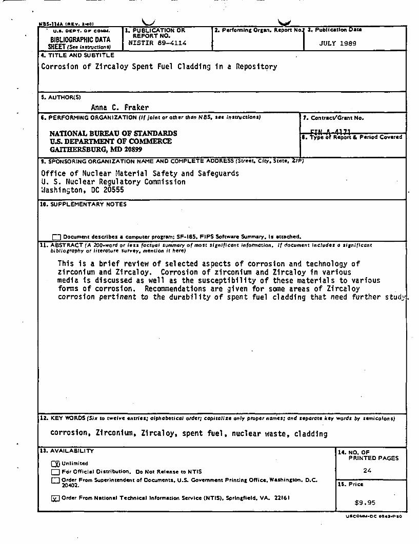
Corrosion of Zircaloy Spent Fuel Cladding in a Repository
IPublication Daut
JULY 1989.
S. AUTHOR(S)
Anna C. FrakerC. PERFORMING ORGANIZATION (if Joint or other than NSS see Instructions) 7. Contract/Grant No.
NATIONAL BUREAU OF STANDARDS . Typeo Report & Period CoveredU.S. DEPARTMENT OF COMMERCEGAITHERSBURG, MD 20899
i. SPONSORING ORGANIZATION NAME AND COMPLETE ADDRESS (Street. City. State. Z)
Office of Nuclear Material Safety and SafeguardsU. S. Nuclear Regulatory CommissionWashington, DC 20555
10. SUPPLEMENTARY NOTES
E] Document describes a computer program; SF-I85. FIPS Software Summary. Is attached.11. ABSTRACT (A 200-word or less factual summary of most significant information. If document Includes a sgnificant
bibliography or literature survey. mention it here)
This is a brief review of selected aspects of corrosion and technology ofzirconium and Zircaloy. Corrosion of zirconium and Zircaloy in variousmedia is discussed as well as the susceptibility of these materials to variousforms of corrosion. Recommendations are given for some areas of Zircaloycorrosion pertinent to the durability of spent fuel cladding that need further stud-
12. KEY WORDS (Six to twelve entries; alphabetical order; capitalize only proper names; and separate key words by semicolons)
corrosion, Zirconium, Zircaloy, spent fuel, nuclear waste, cladding
13. AVAILABILITY 14. NO. OFPRINTED PAGES
U UnlimitedE For Official Distribution. Do Not Release to NTIS 24a- Order From Superintendent of Documents. U.S. Government Printing Office. Washington. D.C. 1 Price
20402. 5Prc
0 Order From National Technical Information Service (NTIS). Springfield, VA. 22161
uscOMM-OC ods-PSO