corrosion protection of lng tank foundations and base ... · pdf file1 corrosion protection of...
TRANSCRIPT

1
Corrosion Protection of LNG Tank Foundations and Base Slabs Using Impressed Current Cathodic Protection
Michael B. Surkein ExxonMobil Development Corporation
12450 Greenspoint Drive Houston, TX 77060
John LaFontaine ExxonMobil Development Corporation
12450 Greenspoint Drive Houston, TX 77060
Hassan Sheikh Jazira Technical Systems
PO Box 85631, Dubai, UAE [email protected]
Abstract Cryogenic insulated tanks used for liquefied natural and petroleum gas are significant assets requiring comprehensive integrity design. Insulated tanks with piled foundation designs may be vulnerable to the damaging corrosive effects of water and chloride migration to the rebar of the piles and the foundation slab. To mitigate these effects impressed current cathodic protection (ICCP) can be applied. To demonstrate the effectiveness of this approach a case history is described. The tank in question was installed in corrosive soil conditions requiring independent custom designed cathodic protection systems for both the pile array and the foundation slab. The design assumptions for the system are presented as well as operational data from the system. Lessons learned from the case history are reviewed. Keywords: "cathodic protection; rebar corrosion; tanks; concrete; impressed current;"

2
Background LNG is liquefied natural gas (methane) that has been cooled to an extremely cold temperature (-260° F/ -162.2° C). Large insulated cryogenic tanks (often up to 75 meters in diameter) are now in common use for storage of liquefied natural gas (LNG) and liquefied petroleum gas (LPG). Storage for LPG and LNG is required at both liquefaction plants as well as receiving terminals located around the world. Such tanks require a double walled insulated construction to ensure the gas remains below the regasification temperature (Figure 1 and 2). The liquid form of these hydrocarbons requires only a small percentage of the storage volume of the gaseous state, hence offering obvious storage and transportation advantages. The reason the industry ships and stores methane as LNG is that when natural gas is cooled to cryogenic temperatures as described above, it changes it from a vapor into a liquid. This reduces the space natural gas occupies by more than 600 times, making it a practical size for storage and transportation.
Figure 1 - Schematic drawing cross section of an LNG Tank
Post-Tension Concrete
Outer Tank Vapor
Thermal Protection
Foundation
Resilient Blanket
Liquid-Containing9-Ni Inner Tank Shell
Reinforced Concrete RoofOuter Roof - Vapor
BarrierInsulation Suspended Deck
Inner Tank Bottom 9-Ni Secondary Bottom
9-Ni
Bottom Insulation Outer Steel Bottom
Concrete Base Slab
Perlite Insulation

3
Figure 2 - Example of LNG tanks under construction
LNG Tank Design for Corrosion Protection and Integrity The integrity of insulated tanks is important given the significant consequences of tank release during operation. The stored hydrocarbon is fully dehydrated hence the potential for corrosion of the internal nickel allow tank membrane during service is considered insignificant. However hydrotest water used during commissioning should not contain chlorides and it would normally be good practice to chemically treat the water to mitigate the corrosive effects of bacteria. Fresh water is typically used to hydrotest these types of tanks, but from time to time seawater has been considered but not normally suitable due to potential corrosion issues. Since the tank foundation is usually reinforced concrete, corrosion of the rebar in the foundation is the most significant threat to the integrity of insulated tanks. Vertical concrete tank walls generally do not require specific corrosion mitigation. Tank walls are typically constructed with low permeability concrete with sufficient cover to prevent water and chloride ingress to the rebar. Depending on site location, the foundations slabs may require piles for support. Slabs without piles can be constructed with a continuous liner system either below or embedded in the concrete which mitigates water ingress from the soil. Where additional support requirements are needed, steel or concrete piles are usually installed with the foundation slab. Unfortunately, such foundation designs require the piles to penetrate into the slab, thus use of a continuous membrane liner is not practical. In the piled foundation configuration leak paths exists around the circumference of the piles at each location where they penetrate the slab. Given the prolonged exposure of piled foundations to water ingress over the design life of the tank, additional corrosion mitigation should be considered to protect the piles and the slab. The most effective method to mitigate the corrosive effects of water and chlorides is cathodic protection.

4
Case History - LNG Tank Cathodic Protection Design In recent years, a tank farm was constructed to provide storage of LNG at a large liquefaction plant in a coastal region. The construction site for the tanks was located on reclaimed land immediately adjacent to the export terminal. The conditions provided by the reclaimed soil required the use of a piled foundation to support the tanks. The resistivity of the reclaimed soil was measured to be approximately 200 ohm-cm with a high concentration of chlorides, indicating the soil would be highly corrosive to carbon steel. Additionally a large percentage of the surface area of the piles would be directly exposed to chloride containing liquid water resulting from the near surface water table. Typically for LNG and LPG storage tanks installed as described previously, a large array of piles are required to support the foundation. The specific tank being discussed required 301 piles averaging 15-m in length by 1-m in diameter. Figure 3 shows an example of the typical pile layout.
Figure 3 - Typical pile layout (301 piles)
The piles were constructed from reinforced concrete. Figure 4 shows the pile top in the as installed condition prior to construction of the base slab. The ends of the rebar cage are visible.

5
Figure 4 - LNG tank foundation showing extent of reinforced concrete piles
Design Basis
Piles
Cathodic protection for buried structures is commonly applied using discreet deepwell or surface ground beds. However near surface ground beds normally provide inadequate current distribution to large areas of such vast pile arrays as included in the design of this tank. The use of deepwell anodes for large, tightly spaced pile arrays was considered impractical due to the depth required for the wells to provide effective current distribution. Thus, for effective application of current throughout the entire array, a distribution of individual anodes in close proximity to each pile was employed. Anodes for such applications may be canistered Iron-Chromium- Silicon (Fe-Cr-Si) alloy pre-packaged with petroleum based coke breeze or mixed metal oxide (MMO) titanium tubulars. Fe-Cr-Si anodes were selected for this specific tank due primarily to local availability (see Figure 5).
Figure 5 - Buried ICCP anode used to protect piles
The anodes were installed in augured holes and pre-determined depth selected to provide optimum current distribution across the length of the piles. Figure 6 shows a schematic of the anode and reference electrode layout for half the tank. There are 54 anodes depicted on the drawing and 13 reference electrodes. About half of the reference electrodes were installed at elevations near the bottom of the piles and the remaining near the top. It was expected that distributing the reference electrodes in this manner would help determine cathodic protection current distribution over the entire pile length.
Rebar at pile top
Piles

6
Figure 6 - Typical layout of anodes and reference electrodes for pile systems
Foundation Base Slab and Slab End The foundation design for the tanks includes a thick base slab constructed of reinforced concrete in a “cage” configuration (more on the rebar layout to be discussed later). To mitigate the effects of chloride-bearing water migrating from underneath the foundation slab, an impressed current ribbon anode system was designed. Figure 7 shows the installation of the mixed metal oxide anode over a layer of lean concrete. After installation and testing, the ribbon anodes are then covered with a grout for physical protection during rebar installation.
Figure 7 - Top of reinforced concrete piles with lean concrete slab
Buried Anode
Reference Electrode
Pile Tops
Mixed Metal Oxide Anode Ribbon
Lean Concrete
7
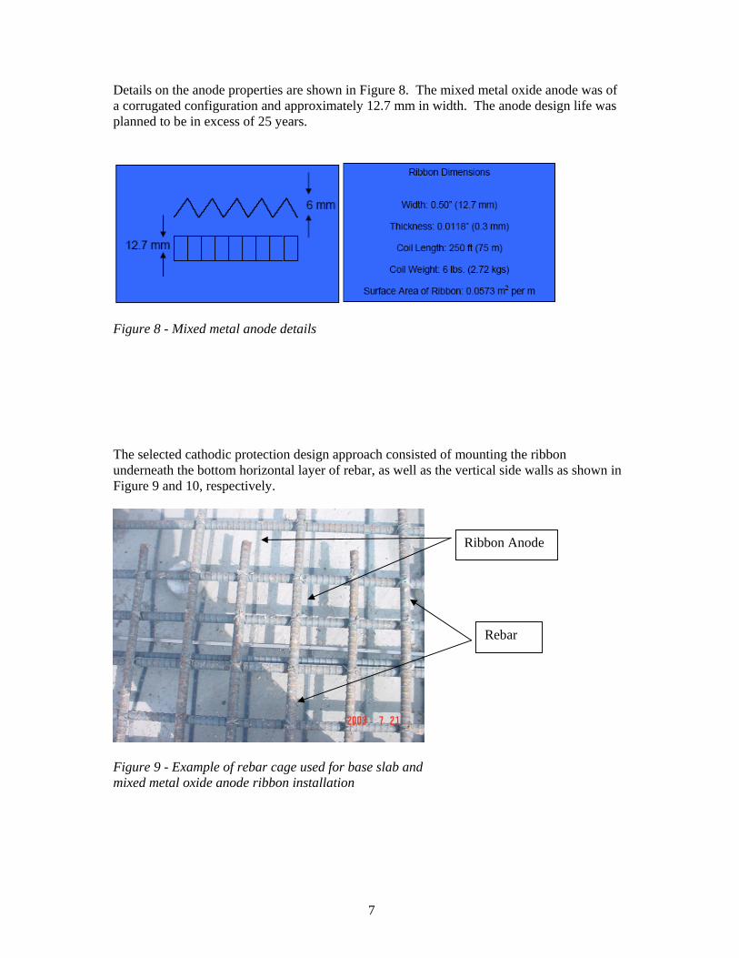
Details on the anode properties are shown in Figure 8. The mixed metal oxide anode was of a corrugated configuration and approximately 12.7 mm in width. The anode design life was planned to be in excess of 25 years.
Figure 8 - Mixed metal anode details The selected cathodic protection design approach consisted of mounting the ribbon underneath the bottom horizontal layer of rebar, as well as the vertical side walls as shown in Figure 9 and 10, respectively.
Figure 9 - Example of rebar cage used for base slab and mixed metal oxide anode ribbon installation
Rebar
Ribbon Anode

8
Figure 10 - Example of rebar cage used for base slab end vertical rebar and mixed metal oxide anode ribbon installation The basis for installing anodes for corrosion protection of the base slab and vertical end rebar is that these sections of rebar normally face the highest risk of contact from ground water migration. The installation for the vertical side rebar requires the use of plastic isolators to assure no electrical continuity between the anode and the rebar. As a consequence of this approach, it was necessary to develop appropriate quality control procedures to ensure that the anode and reinforcing steel do not electrically short. Earlier work by others highlighted the importance of electrical surveys during construction to assure no electrical shorts are present1. Typical of ribbon anode systems, uniform current distribution to the reinforcing steel is achieved by minimizing spacing of the anode ribbons. The base slab is constructed with reinforcing steel density that varies along its radius – from dense to less dense as the center of the foundation is approached. To match this changing steel density, the anode spacing was reduced where the steel was at its most dense in a zonal approach to be discussed later. Conversely, the spacing was increased where the steel density decreased. The ribbon anode array was interconnected using uncoated titanium conductor bar. Electrical connections to the conductor bar were completed via custom made cable-to-titanium connections that were spot welded to the conductor bar. The cable tail of these connections was routed to the junction box. Figure 11 shows an example of a finished slab.
Ribbon Anode
Rebar
Plastic Isolators

9
Figure 11 - Completed base slab edge (actual slab height is 0.875 m)
Current Density The current density requirements of concrete ICCP systems are dependent on the quality of the concrete, the presence of chlorides and the level of oxygen present. Literature indicates the use of current density values ranging from 5 (mA/m2) to 25 (mA/m2)2. In addition, for new concrete, it is possible to achieve protection by using significantly less current density; in the range of 1.0 (mA/m2) to 2.0 (mA/m2)3 for new concrete. Based on the above information, it was decided to use a current density of 5 (mA/m2) for both systems. In addition, the design would also ensure that sufficient capacity would be available in the system to operate slightly beyond the chosen current density. To assure the cathodic protection current would adequately spread to all rebar surfaces the base slab was divided into four zones as shown on Figure 12.

10
Figure 12 - Example of anode layout for Base Slab Zones 1-3. Zone 4 is the slab end surfaces as shown in Figure 10 and 11. Although design calculations showed that there would be enough cathodic protection current capacity available, the zonal approach would help assure cathodic protection would be achieved. Table 1 shows the calculated cathodic protection currents needed. Also, to assure that the anode arrays for both the pile and base slab systems would provide sufficient and uniform current to the reinforcing steel, it was necessary to check and confirm that attenuation effects on anode output would not be detrimental. Standard calculations were used to confirm attenuation would not be a problem.
Anode Feeder Cables - Zones 1-3
Zones 1-3

11
Table 1 - Basic LNG Tank Design Information Design Information Current
Required Foundation slab diameter 74.3 m Outer tank bottom diameter 73.3 m Number of piles 301 Pile Diameter 1 m Pile rebar surface area 25.4 m2 Pile length ~ 15 m Design current density 5 mA/m2 Total pile rebar surface area 7,645 m2 38 A Foundation slab rebar surface area 10,716 m2 Outer tank bottom shell plate area1 4,220 m2 Heating conduit area 435 m2 Anode quantity for piles 110 Surface Areas Foundation Slab Zones
Foundation slab - Zone 1 2,266 m2 11.3 A Foundation slab - Zone 2 4,723 m2 23.6 A Foundation slab - Zone 3 5,930 m2 29.7 A Foundation slab - Zone 4 342 m2 1.7 A
Total for Foundation Slab Zones 13, 261 m2 66.3 A Slab height 0.875 m Notes 1. Outer tank bottom shell coated so only include 50% for design
Reference Electrodes To provide feedback on the performance of the ICCP system, reference electrodes were installed in the base slab and the foundation piles. The reference electrodes used were silver: silver chloride (Ag/AgCl). For the base slab, these reference electrodes were positioned on the reinforcing steel and secured using cable ties. The reference electrodes were tested for accuracy prior to casting; they were once again tested 24hrs after casting. The cable from each of reference electrodes was extended to the junction boxes. For the foundation piles, the reference electrodes were positioned at either one of two elevations; one meter from the bottom of the toe level of the pile, and one meter from the top of the pile. Some piles had reference electrodes at both elevations. Figure 10 shows an example of typical reference electrode locations used to monitor the pile cathodic protection system. The standard approach typically used for monitoring LNG tank pile cathodic protection systems included installing enough reference electrodes to total 10% of the pile quantity. Thus, for this case only 30 reference electrodes would be needed. However, for added redundancy, there were 40 total Ag/AgCl reference electrodes installed for monitoring the piles. After installation only 38 were functional.

12
For the base slab, the eight reference electrodes were positioned over areas that corresponded to the anode zones. Two reference electrodes were installed per zone. There was no need for additional redundancy as close current measurement per zone would accurately show if cathodic protection current is reaching the rebar.
Transformer Rectifiers The ICCP systems for the base slab and the foundation piles are operated by two independent oil cooled transformer rectifiers. One transformer had one circuit rated at 100 Amps and 30 Volts and the other had two circuits each rated at 30 Amps and 30 Volts. The units are capable of operating in constant current or constant voltage. In addition, the units are equipped with interrupters to allow for instant off readings. The transformer-rectifier units were placed close to the tank and therefore were certified for hazardous area operation.
Commissioning Commissioning of the base slab and piles cathodic protection systems was carried simultaneously. The general approach was to energize the transformer rectifiers system at 10% of the design output, and thereafter gradually increase the current output to achieve protection criteria. The criterion for achieving protection is 100mV polarization shift from the natural potential2. The commissioning data for the transformer rectifiers are shown in Table 2. The data represents the periodic measurements of the transformer rectifier current and voltage outputs. Additional discussion regarding the data will be presented later. Table 2 - Commissioning Data - Transformer Rectifier Outputs
Pile Cathodic Protection - Transformer 6 Channel 1 - 30 Amp Capacity Output Day 1 Day 2 Day 7 Day 10 Day 11 Day 21 Current, Amps 19 19 19.3 19.5 20 19.8 Voltage, Volts 4.2 4.2 5.5 5.6 5.7 5.9
Pile Cathodic Protection - Transformer 6 Channel 2 - 30 Amp Capacity Output Day 1 Day 2 Day 7 Day 10 Day 11 Day 21 Current, Amps 19 19 19 21.9 21.9 23.6 Voltage, Volts 4.2 4.2 5.2 5.8 5.9 6.3
Slab Cathodic Protection - Transformer 7 - 100 Amp Capacity Output Day 1 Day 2 Day 7 Day 10 Day 11 Day 21 Current, Amps 35 35 35.1 35.5 35.5 35.3 Voltage, Volts 6.3 6.3 6.6 6.6 6.7 6.7
Foundation Piles Cathodic Protection System The commissioning data for the pile cathodic protection system are shown in Tables 2, 3 and 4.

13
Table 3 - Commissioning Data Pile System Surface Area = 7,645 m2 Day 1 Day 2 Day 7 Day 10 Day 11 Day 21Current Density, mA/m2
4.97 4.97 5.0 5.28 5.48 5.68
Slab System Surface Area = 13,261 m2 (plus additional steel surfaces in slab) Current Density, mA/m2
2.64 2.64 2.65 2.68 2.68 2.66
Slab System Surface Area = 10,716 m2 (rebar only) Current Density, mA/m2
3.27 3.27 3.28 3.31 3.31 3.29
Table 4 - Commissioning Data for Piles
Potentials for bottom reference location (16 electrodes) Readings are -mV vs. Ag/AgCl Reference)
Ref Native
Potential Day 1 Day 2 Day 7 Day 10 Day 11 Day 21
Instant
Off Instant
Off Instant
Off Instant
Off Instant
Off Instant
Off Polarization
Shift 1 252 384 395 422 425 427 410 158 3 763 854 863 896 907 911 935 172 5 775 974 882 922 935 940 964 189 7 773 898 907 947 958 962 976 203 9 320 468 478 510 518 521 531 211 11 766 937 949 974 980 982 994 228 12 104 209 206 220 232 237 263 159 14 776 896 891 902 914 918 954 178 15 648 846 853 874 878 880 886 238 16 772 905 915 955 963 966 977 205 18 +74 46 46 78 91 93 114 188 20 787 880 887 925 938 942 960 173 22 777 907 815 954 964 969 982 205 24 697 933 841 957 964 965 981 284 26 788 909 916 948 955 957 965 177 M1 349 615 627 663 670 673 687 338 Avg. 623 207

14
Table 4 - Commissioning Data for Piles - continued
Potentials top reference location (22 electrodes) Readings are -mV vs. Ag/AgCl Reference)
Ref Native
Potential Day 1 Day 2 Day 7 Day 10 Day 11 Day 21
Instant
Off Instant
Off Instant
Off Instant
Off Instant
Off Instant
Off Polarization
Shift 2 759 939 943 968 976 975 993 234 4 748 997 996 1003 1007 1009 1023 275 6 755 951 962 999 1008 1010 1022 267 8 749 975 985 1012 1019 1020 1031 282 10 757 961 972 998 1002 1003 1015 258 13 727 950 961 991 995 994 1005 278 17 727 890 899 937 947 950 969 242 19 760 912 923 959 966 969 980 220 21 743 937 814 979 984 984 992 249 23 804 910 820 959 972 976 996 192 25 773 928 837 961 971 975 989 216 33 566 799 805 828 839 838 854 288 34 735 963 971 997 1005 1008 1024 289 35 695 958 968 979 982 982 988 293 36 679 946 953 968 972 973 986 307 37 679 907 916 940 949 948 959 280 38 424 547 556 594 606 605 623 199 39 764 996 1002 1016 1024 1026 1049 285 40 667 923 929 941 958 949 965 298 41 733 971 980 997 1005 1006 1025 292 42 699 937 942 954 958 958 971 272 M2 265 708 716 751 761 764 781 516 Avg. 712 263 Natural or native potentials, versus Ag/AgCl reference electrode, were initially recorded for the piles. The potentials for the pile rebar measured using reference electrodes installed near the bottom of the 15 m long piles ranged from a high of + 74 mV to a low of -788 mV. The potentials for the pile rebar measured using reference electrodes installed near the top of the piles ranged from -265 mV to -804 mV. Other than the +74 mV mentioned earlier, all other potential measurements were negative as would be expected. It was noted that the native potentials, as exhibited by reference electrodes placed at the top of the pile were more electronegative than those at the bottom, the difference being in the range of 80mV. This indicated that perhaps the top of the piles were more corrosion active than the bottom. Initially the transformer rectifiers were energized at 10% of the design current and resulted with minimal polarization. Therefore, the output of the transformer rectifiers were gradually increased until rapid polarization was observed. This occurred at about 50% of design

15
current. The system was left for approximately one week so that all the reference electrodes would exhibit 100mV polarization as required by the project specification. Potential readings were taken once a day during that period. Prior to the completion of the 1-week period, all reference electrodes exhibited 100mV polarization. These results and additional data taken for 21 days are also shown in Table 4. For the pile rebar surface area, it was found that a current density of 5.7 mA/m2 was required for complete polarization. The design current basis was 5.0 mA/m2. The required current density should be expected to reduce with time as is common for impressed current cathodic protection systems. Also, it should be noted that due to the previously discussed attenuation analysis a considerable extra amount of ribbon is present and the transformer rectifiers are only operating at only 2/3 of rated current capacity, so if needed additional current would be available. The operational current density will be periodically monitored.
Base Slab Cathodic Protection System The commissioning data for the pile cathodic protection system are shown in Table 2, 3 and 5. Natural or native potentials, versus Ag/AgCl reference electrode, were initially recorded for the reference electrodes installed within the base slab. The potentials for the base slab rebar ranged from -36 mV to - 215 mV. These values are considerably more positive than the potentials measured from the piles. Table 5 - Commissioning Data for Base Slab
Readings are -mV vs. Ag/AgCl Reference) - (8 electrodes)
Ref Native
Potential Day 1 Day 2 Day 7 Day 10 Day 11 Day 21
Instant
Off Instant
Off Instant
Off Instant
Off Instant
Off Instant
Off Polarization
Shift 28 94 223 239 279 285 328 241 147 30 36 285 327 426 449 462 499 463 M4 215 385 412 478 481 475 498 283 27 Not function 29 27 82 87 98 101 101 106 79 31 52 155 163 197 204 207 518 466 32 75 174 176 187 186 187 191 116 M3 Not function Avg. 83 259 Initially the transformer rectifiers were energized at 10% of the design current and resulted with minimal polarization. At 50% of the design current, rapid polarization was observed. The system was left for approximately one week so that all the reference electrodes would exhibit 100mV polarization. Potential readings were taken daily during that period. Prior to the completion of the one week period, all functioning reference electrodes exhibited 100mV polarization. Two reference electrodes did not function properly. However, measurement of current output to the zonal area where the reference electrode is located showed current in the range of the other zones. This coupled with all other reference electrodes showing

16
exceptional polarization, helps indicate the system is functioning properly. Based on this reference electrode performance issue, it would be good practice to install extra redundant reference electrodes. This will become standard practice for future installations. The current density being experienced was only 60% of the design current. The design current density was 5.0 mA/m2 versus the approximately 3 mA/m2 being experienced. This could be explained as the rebar is deep inside a large cast concrete slab, with initially little chlorides or oxygen to require more cathodic protection current. It is suggested that reducing the design current density normally isn't necessary as the quantity of ribbon anodes that is necessary for adequate distribution drives the design capacity.
Conclusions Operational data received thus far indicates that the cathodic protection system is mitigating corrosion of the rebar in the foundation as designed. The use of cathodic protection for this unique application provides support for the following specific conclusions:
• In order to provide cathodic protection for foundation slabs, an embedded impressed current anode ribbon system is required. Thus, the cathodic protection system must be installed during construction of the tank and can not be applied in a retrofit after construction of the tank is complete. Additionally, it is suggested that the need for a distributed anode system for protection of the piles requires that the pile anode array must be installed in advance of the foundation slab construction.
• To achieve the required potential criteria for full protection of the rebar within the
piles, a steady state current density as high as 6 mA/m2 is needed. This value represents a significant current drain, indicating that the rebar would indeed corrode if cathodic protection were not applied. Although the operating current drain from the CP system is greater than the design steady state value, additional reserve capacity in the CP system was sufficient to account for it.
• The operational current density required to achieve the protection criteria for the slab
cathodic protection system was approximately 3.3 mA/m2 compared to the design basis of 5.0 mA/m2. The increased current demand of the piles compared to the slab is in part due to the piles more direct exposure to chloride bearing ground water.
• In the native state potentials of the pile rebar are more active towards the top of the
pile than the bottom. This indicates the top of the piles require additional current to achieve protective polarization than deeper sections.
• The use of an array of distributed impressed current anodes is a valid design approach
for cathodic protection of insulated tank foundation piles. The ribbon installation method must ensure that the ribbon anode does not contact the slab rebar during the concrete pour.
• Failure of a significant percentage of reference electrodes resulting from installation
damage justifies the need for system redundancy in the monitoring system.

17
References
1. Surkein, M. B., Manian, L., "Remediation of a New Reinforcing Steel Cathodic Protection System During Construction, Materials Performance; Vol./Issue: 38:5, 1999
2. British Standard EN12696:2000, Cathodic Protection of Steel in Concrete