corrosion testing of the general electric mantech...
TRANSCRIPT

!!-
SAND76·8055
Unlimited Release
Corrosion Testing of the General Electric Mantech GAU alA Penetrator
. L J. Weirick
When printing a copy of any digitized SAND Report, you are required to update the
markings to current standards.

I ssued by Sandia Laboratories, operated for the United States Energy Research and Development Administration by Sandia Corporation.
NOTICE
This report was prepared as an account of work sponsored by the United States Government . Neither the United States nor the United States Energy Research and Development Administration, nor any of their employees, nor any of their contractors, subcontractors, or their employees, makes any warranty, express or implied, or assumes any legal liability or responsibility for the accuracy, completeness or usefulness of any information , apparatus, product or process disclosed, or represents that its use would not infringe privately owned rights.
"
..
I

"
. .
r
SAND76-8055 Unlimited Release
Printed February 1977
CORROSION TESTING OF THE GENERAL ELECTRIC MANTECH GAU 8/A PENETRATOR*
L. J. Weirick Metallurgy and Electroplating Division 8312
Sandia Laboratories
ABSTRACT
The corrosion resistance of the U-3/4 Ti alloy selected as the ammunition "kinetic energy penetrators" to be used in the U. S. Air Force rapid-fire gun (GA U-8/ A) has been studied. Corrosion testing showed that neither the chemistry nor the metal processing variables examined caused a change of practical significance in the material's corrosion response in either salt fog or moist nitrogen. Based upon the data obtained, a coating system to protect the penetrators during long-term storage is not necess ary.
>!<Funding for this program was provided by the U. S. Air Force under Project Order No. FYXPOO-76P-1113.
3/4

"
. .
;
TABLE OF CONTENTS
Introduction
General Electric Mantech GA U 8/ A Penetrator Program
Goals of Program
Uranium Alloy Corrosion
Metallic Coatings on Uranium Alloys
Material Specification
Chemistry
Metal Processing
Solution Treatment
Aging
Encapsulation
Corrosion Tests
Salt Fog Testing
Hot Moist Nitrogen Testing
Test Series I
Test Series II
Costed Penetrators
Rod Samples
Cold Straightened Penetrators
Encapsulated, Corrosion Tested, and Fire Tested
Summary
Conclusions
Appendix
References
Page
11
11
11
12
12
13
13
13
14
15
15
15
15
16
17
30
40
40
44
44
44
46
47
49
5/6

· .
ILL USTRA TIONS
Figure Page
1. Weight Loss Versus Time for AFML and Lot lA 19 Penetrators in Salt Fog
2. Compilation of Weight Loss Data for Penetrators in 20 Test Series I
3. Weight Loss Versus Time for AFML and Lot lA 25 Penetrators in Moist Nitrogen
4. Weight Loss Versus Time for Lots 6, 16, 19, and 27 21 in Moist Nitrogen
5. Weight Loss Versus Time for Lots 2 and 14 in 28
· Moist Nitrogen · 6. Weight Loss Versus Time for Lots 3A and 3B in 29
Moist Nitrogen
7. Weight Loss Versus Time for AFML and Lot 11 32 Penetrators in Salt Fog
8. Weight Loss Versus Time for AFML and Lot 6A 33 Penetrators in Salt Fog
9. Weight Loss Versus Time for AFML and Lots 2 34 and 10C Penetrators in Salt Fog
10. Compilation of Weight Loss Data for Penetrators 35 in Test Series II
11. Weight Loss Versus Time for Lot 5, Test Series II, 36 in Moist Nitrogen
12. Weight Loss Versus Time for Lot 6A, Test Series II, 39 in Moist Nitrogen
13. Compilation of Weight Loss Data for Rod Samples 43 in Salt Fog
14. Response to Salt Fog of Cold Straightened Penetrators 45
7/8

..
TABLES
Table Page
I. Process Data for Forged DU Penetrators 18
II. Test Series I--Salt Fog Results (Solution Treatment - 21 1500°F, 180 Minutes, Salt)
III. Test Series I--Salt Fog Results (Solution Treatment - 22 1500°F, 30 Minutes, Pb)
IV. Test Series I--Salt Fog Results (Solution Treatment - 23 None)
V. Production Plan: Test Series II· 31
VI. Test Series II Penetrators - Moist Nitrogen Results 38 . . VII. Rod Samples - Salt Fog Test 41
VIII. Rod Samples - Moist Nitrogen Test 42
9/10

..
. . . CORROSION TESTING OF THE GENERAL ELECTRIC
MANTECH GA U 8/ A PENETRA TOR
Introduction
General Electric Mantech GAU 8/A Penetrator Program
General Electric, Armament Systems Department, Aircraft Equipment Division, Burlington, Vermont, is the prime contractor for the U. S. Air Force rapid-fire gun (GAU-8/A) for the A-tO ground support aircraft. The ammunition for this gun is a new type called "kinetic energy penetrators." The material selected for the 30-mm round for the GA U-8/ A is a uranium-O. 75 weight percent titanium (U-3 /4 TO alloy. General Electric's responsibility in terms of the ammunition was to demonstrate the technical and economic feasibility of manufacturing uranium alloy penetrators using full-scale production techniques.
The main criterion used to evaluate the adequacy of the material produced was ballistic performance. However, because U-3/4 Ti is a lean uranium alloy, the corrosion resistance of the uncoated alloy was also a major concern. Sandia Laboratories, Livermore (SLL) was requested by the Air Force to assist GE in examining the material produced by a number of suppliers using numerous production routes and to make a final recommendation on the necessity of protectively coating the alloy.
Goals of Program
The major goal of this study was to establish relationships between certain material chemistry or metal processing variables and the general corrosion resistance of the uranium alloy or its stress corrosion cracking (SCC) susceptibility. This corrosion testing program was a screening study rather than the development of a test procedure, costing system, or theoretical mechanism for uranium alloy corrosion. The primary chemistry
11

variables investigated were titanium content; carbon, hydrogen, oxygen, and nitrogen interstitial impurity effects; and some substitutional impurity (e. g., Fe, Ni, CU, SO effects. The primary processing variables were the process itself (extrusion versus swaging versus forging), the temperature at which this process was done, the solution heat treatment temperature, the aging temperature, and the severity of the quench.
The second goal of this corrosion testing was to identify any analogous variables in material chemistry or metal processing which prevented the proper application of a protective metallic coating.
Uranium Alloy Corrosion
Of the significant number of papers in the open literature concerning the corrosion of uranium and uranium alloys, two recently published manuscripts deserve special mention. First, a review paper by Orman! details the different corrosion mechanisms responsible for the widely different corrosion rates and corrosion products obtai.ned when testing in differing environments. Briefly, Orman discusses the reasons for the increased corrosion rate measured for uranium alloys tested in moist nitrogen depleted of oxygen versus that obtained when testing in moist air. Similarily, the reasons for the increase in corrosion rate in the presence of chloride are outlined.
The second paper is of special interest because it documents the work done on the Air Force GAU 8 uranium alloy penetrators, which immediately preceded this present program. This paper by Weirick, Johnson, and Dini2 gives the details of the electroplating process for applying the metallic coating, as well as its usefulness in preventing corrosion of the uranium alloy. Also included is the data on the corrosion response of "typical" uranium-3/4 titanium in moist air, moist nitrogen, and salt fog environments.
Metallic Coatings on Uranium Alloys
A recently published review paper by Weirick3 on the use of protective coatings (oxides, organic films, and metallic platings) to improve the corrosion resistance of uranium alloys shows that metallic platings have been and continue to be the most promiSing. Extensive work at Sandia Laboratories, Livermore (SLL) has shown that good corrosion resistance is obtained for uranium and uranium alloys by plating with nickel. 4-6 For severe corrosive environments, a duplex coating of nickel plus electroplated zinc with a zinc chromate finish was found to provide even better results. Details of the electroplating process are given in the appendix.
12

Material Specification
Chemistry
Details on the chemistry of the material tested in this program are given in a Battelle Columbus Laboratories report. 7 Briefly. there were two main chemistry variables explored: carbon and hydrogen. The carbon content ranged from a minimum of 30 parts per million (ppm) to over 900 ppm. The carbon in the uranium alloy at the lowest level is most probably in solid solution. whereas the carbon at the highest level is most probably existing in the uranium matrix as titanium carbide particles. As stated in a previously referenced report. 2 carbide particles can significantly influence the corrosion resistance of a uranium alloy.
The hydrogen content of the material was either relatively low (2 ppm) or much higher (10 ppm). The difference was due to the manner in which the gamma soli.l.tionizing of the material was done. If the material is heat treated in vacuum. the hydrogen is extracted from the uranium alloy. whereas if the heat treating is done in a molten salt bath. more hydrogen ingresses into the material. Past experience suggests that the amount of hydrogen in the material may affect the stress corrosion cracking resistance of the material but should not affect the general corrosion resistance.
The only other chemistry variables with any significant variation were titanium. O. 6 to 1. 0 percent. and iron. 188 to more than 400 ppm. The richer the alloy is in titanium. the more corrosion resistant it should be. The effect of iron as a substitutional impurity is unknown. The levels of copper. magnesium. and silicon were monitored but not systematically changed.
Metal Processing
The three techniques for metal processing investigated were extrusion. forging. and swaging. The details for extrusion are given in reports8• 9 submitted by Nuclear Metals. Inc. (NMI) and Reactive Metals. Inc. (RMI). The details for forging are documented10 by Omark Industries and for s waging by NMI. 8
Briefly. the major variables examined in the extrusion study were extrusion temperature and ram speed. Extrusion temperatures in the vicinity of 1150 to 1200°F caused the uranium alloy to be worked in the "a"
13

state. At 1275 to 1350°F, the microstructure of the uranium alloy is primarily "/3". * Extruding the material in the "y" state was done between 1500 and 1550°F. Ram speeds were increased with correspondingly higher extrusion temperatures. Past experience with uranium alloys, primarily in the uranium-niobium system, suggests that the "y" alloys are the most corrosion resistant. "a" alloys the least corrosion resistant. and "/3" alloys less consistent but usually in the middle in comparative corrosion resistance. Ram speed would not be expected to alter the corrosion resistance of a given material.
Forging was done on blanks made from extruded rod. The rod had been extruded in either the "a" or "y" condition. Some blanks were forged in the as -extruded condition, and others were forged after a solution treatment. In addition to the remarks previously made concerning the relative corrosion resistance of a and y material. one would predict no significant effect on corrosion resistance due to the sequence of forging and solutionlzmg. However, the differing states of cold work produced in the material by the alternate preparations may affect the stress corrosion cracking susceptibility of the material.
Swaging was done on blanks made from rod extruded in the "/3" range, 1310°F. Some blanks were swaged in the as-extruded condition, and others were swaged after a solution treatment. As stated previously, these variables could produce a change in the see resistance of the material but the corrosion resistance was not expected to change.
All of the as -extruded, forged, or swaged blanks which were or were not subsequently solutionized and/ or aged were final ground to the specified penetrator dimensions by Omark Industries.
Solution Treatment
The solutionizing treatment was done at 1500 to 1550°F for either 30 or 180 minutes. The heat transfer medium used was either a molten chloride salt or a molten lead or lead/tin bath. Heat treating material which has been either a or /3 extruded should improve its corrosion resistance. Heat treating material which had been y extruded should have a minimal effect. regardless of whether the material is subsequently forged or swaged. However. solutionizing should relieve any internal stresses produced by the metal working processes and increase the material's resistance to see.
14
>!< For the purpose of brevity in this report, the nomenclature "/3" will be used to symbolize an extrusion condition between 1275 and 1350°F. This is not meant to confer a precise definition of the metallurgical state of the alloy.

.-
Aging
Aging treatments were done at temperatures between 775 and 1l00°F for times from 50 to 960 minutes. The heat transfer mediums used were vacuum, dry argon, molten lead, or molten lead/tin. Some material was subsequently quenched in oil, some in water, and some material was left to slow cool. A previous publication3 stated that aging U-3/4 Ti produced only a minimal change in the corrosion response. Thus no drastic changes in corrosion resistance were expected as a function of aging temperature, aging time, or aging medium.
Earlier work by Magnani11 on the SCC susceptibility of U-3/4 Ti as a function of aging treatment showed that aging to a higher strength level caused a reduction in the resistance to SCC.
Encapsulation
A penetrator or two taken from each combination of material conditions was encapsulated by Aerojet Ordinance and Manufacturing Corp. (AOMC). Details of the encapsulation materials and process are competition sensitive and therefore have not been included. Briefly, the point of concern is that the encapsulation is not meant to hermetically seal the uranium penetrator from the environment. Therefore, any air cavity around the penetrator could communicate with the external atmosphere, which could possibly contain significant amounts of water vapor.
Corrosion Tests
Salt Fog Testing
Purpose--The salt fog test was conducted to determine the resistance of materials to the effects of a salt atmosphere. Because it is an accelerated corrosion test, the results may not correlate with any realistic environment. However, the relative resistance of specimens or coatings on specimens to a salt atmosphere can usually be determined from the results of a salt fog test.
Apparatus--The apparatus used for the salt fog testing was a Model MX-9204 salt fog chamber manufactured by Associated Environmental Systems. The chamber is of double-wall construction with air at 35°C continuously recirculating inside each wall. The salt atmosphere is generated by a nozzle which uses compressed air to siphon the salt solution from the reservoir and atomizes it into a fog. The compressed air is first heated and saturated by bubbling it up through 50°C water in the saturation tower.
15

Solution--The salt solution is prepared by dissolving 5 parts by weight of sodium chloride in 95 parts of hot, distilled water. The salt used is "analyzed reagent grade" sodium chloride. The solution pH is maintained between 6. 5 and 7.2.
Preparation of Test Specimens - -The specimens were cleaned with acetone, rinsed with methanol, and air dried.
Performance of Test--The penetrators were positioned vertically with their butt ends resting on a plexiglass base. The positioning was so that there was no interference between penetrators. Tests were run for five cycles with a continuous 48 hours per cycle.
Evaluation of Results--Photographs of specimens were taken before and after tests for visual documentation of test results. The change in weight due to exposure for each specimen was plotted as a function of time to determine relative corrosion rates. The large diameter of each encapsulated penetrator was measured after each cycle in order to follow any possible swelling reaction. After the corrosion test, the encapsulation was removed and the penetrator examined for any possible deterioration.
Hot Moist Nitrogen Testing
Purpose--The hot, moist nitrogen test was conducted to determine the resistance of materials to the effects of hot water vapor in the absence of oxygen. This test is particularly applicable to uranium alloys because their corrosion resistance is significantly lower in water-containing environments that are also deoxygenated. This test is thus extremely useful for determining the relative resistance of uranium specimens or coatings on uranium specimens to humid environments.
Apparatus--The apparatus used was custom built from a design developed at the Lawrence Livermore Laboratory. 12 Briefly, the specimens are suspended from a lazy-susan contained within a stainless steel chamber that is submerged in an oil bath maintained at 70°C. Connected to the chamber is a gas saturator set to control the dew point at 65°C, thus maintainj.ng the relative humidity at 95 percent. The carrier gas for the humidity system is deoxygenated nitrogen with the oxygen content maintained below two ppm. Specimens are periodically weighed in situ through a nitrogen-purged glove box by means of a Mettler H315 microbalance.
Environment--The environment is deoxygenated nitrogen maintained at 70°C and containing 95 percent relative humidity. It is controlled in a near static condition, with only a slight positive pressure being maintained.
16
-.

;
Preparation of Test Specimens--The specimens were cleaned with acetone. rinsed with methanol. and air dried.
Performance of Test--A platinum wire loop was spot-welded to the tip of each penetrator to provide a means of suspending the penetrator in a vertical position in the chamber. as well as allowing in situ weight measurements. The positioning of penetrators was such that there was no interference between penetrators. Weight measurements were made after each 96 -hour cycle. with a total of eight cycles per test.
Evaluation of Results--Photographs of specimens were taken before and after tests for visual documentation of test results. The change in weight due to exposure for each specimen was plotted as a function of time to determine relative corrosion rates. The large diameter of each encapsulated penetrator was measured after each cycle in order to follow any possible swelling reaction. After the corrosion test, the encapsulation was removed and the penetrator examined for any evidence of deterioration.
Test Series I
Penetrators tested in this series consisted of material whose chemistry was controlled and metal processing was done primarily by Battelle. The chemistry and processing variables for this material, as identified by lots, are given in Table 1. The chemistry and material processing history of Lot 1 is closely analogous to the material used in the previous study 2 for the Air Force Materials Laboratory (AFML). The material contained a carbon content near 50 ppm with a 10-ppm hydrogen level. The material was extruded into rods in the "a" condition, solutionized in a molten salt bath at 1500°F for 180 minutes, aged in a molten lead bath at 850°F for 75 minutes. and water quenched; this processing produced a hardness near 45 Rc. A plot of weight loss versus time for the AFML penetrators tested in salt fog is given in Figure 1 as the dashed curve. The data points shown are for the three penetrators tested from Lot 1A. The data shows that there was no measurable difference in the corrosion rates of the two classes of penetrators--i. e., GE Mantech Battelle versus AFML. Thus two material processors using analogous techniques have apparently produced penetrators with similar metallurgical properties.
In this environment. the penetrators lost weight because of the formation of nonadherent oxides and chloride complexes. The weight loss curve in Figure 1 shows that there was an incubation time of about one day during which the corrosion process was beginning and accelerating. During this time period, the chloride ion in the salt fog was progressively destroying the tarnish film of titanium-rich13 uranium dioxide which had been providing some protection to the uranium-titanium alloy. When this surface tarnish film was completely gone and the penetrator surface was being uniformily attacked. the corrosion rate became linear from two to ten days.
17

Lot No.
1A
1B
2
3A
3B
4
5
8
9
lOA
lOB
11
12
13A
13B
14
15A
15B
16
17
18
19
20
21
22A
22B
23
24
25
26A
26B
27
28
29A
29B
30
31
32
33
18
TABLE I
PROCESS DATA FOR FORGED DU PENETRATORS
Extrusion Temp (oF)
1200/1275
1200
1200/1275
1200/1275
1275
1200/1275
1350
1350
1200
1350
1350
1350
1350
1200
1200/1350
1200
1200
1200
1200
1200
1200
1200
1500
1500
1500
1500/1350
1500
1500
1500
1500
1500
1500
1500
1500
1500
1500
1500
1500
1500
1500
1500
~
Carbon (ppm)
54
43
64
64
57
60
74
111
30
127
80
135
68
30
63
416
416
179
230
218
218
913
54
54
71
85
79
79
79
87
90
85
85
101
98
104
133
330
330
330
330
Pb - molten lead batb salt - molten salt bath A - argon gas V - vacuum WQ - water quench SC - slow cool
Hydrogen (ppm)
10
10
10
2
2
2
10
2
10
2
2
2
2
2
2
10
10
10
2
2
2
10
10
10
2
2
10
10
10
2
2
2
2
10
2
2
2
10
10
2
2
Solution Treatment Temp Time Atmos
(OF) (min)
1500
1500
1500
1500
1500
1500
1500
1500
1500
1500
1500
1500
1500
1500
1500
1500
1500
1500
1500
1500
1500
1500
1500
1500
1500
1500
1500
180
180
180
30
30
none
180
none
180
none
30
30
30
30
none
180
180
180
30
30
none
180
180
180
none
none
180
180
180
none
none
30
30
180
none
none
none
180
180
none
none
salt
salt
salt
Pb
Pb
salt
salt
Pb
Pb
Pb
Pb
salt
salt
salt
Pb
Pb
salt
salt
salt
salt
salt
salt
Pb
Pb
salt
salt
salt
Aging Treatment Temp Time Atmos Cooling
(OF) (min)
850
850
850
850
850
775
850
850
850
775
775
775
850
850
850
1100
850
850
850
850
850
775
775
775
1000
1000
775
1100
850
850
75
50
none
50
50
none
75
none
240
720
none
50
50
240
none
240
240
none
75
60
none
none
75
90
none
960
75
60
none
60
960
240
240
240
none
120
120
90
90
60
960
Pb
V
V
Pb
Pb
Pb
V
A
Pb
V
Pb
V
Pb
A
Pb
A
V
Ph
A
A
V
Ph
V
Pb
Pb
A
Pb
A
A
V
WQ
SC
SC
WQ
WQ
WQ
SC
SC
WQ
SC
WQ
SC
WQ
SC
WQ
SC
SC
WQ
SC
SC
SC
WQ
SC
WQ
WQ
SC
WQ
SC
SC
SC
Hardness (Rc)
44
46
34
47
46
33
46
37
40
34
37
51
49
46
34
35
38
33
46
46
32
28
41
37
42
39
45
46
41
38
40
44
41
40
'44
37
38
46
38
46
38

,-
12 SALT FOG
Lot #1 Ext. - a Soln. - 180 min. salt Age - 850°F 75 min. Pb
• lA - 1425 /~ o 1 A - 1429 /
/ " lA - 1433 /
S2 8 0/
" / • V"l V"l ./' 0 / ....J AFML 0/ l- \,.../ ~ :::c c:.::> !.J..J
$: 4 /
,,-~/ /
/ ,,-
/'"
.......- .......... ~
0 ---0 2 4 6 8 10
DAYS
Figure 1. Weight Loss Versus Time for AFM L and Lot 1 A Penetrators in Salt Fog
Similar corrosion behavior was observed for all of the penetrators tested in salt fog for Test Series r. Figure 2 shows a compilation of all the weight loss data taken for penetrators in Test Series I; the curve for AFML material is also included for comparison. As can be seen from Figure 2, the corrosion response of the AFML material.is bracketed by the corrosion rates observed for penetrators of various lots in Test Series I. Secondly, the bracket taking in all of the data points is very narrow, considering the numerous variables examined. The percentage increase in corrosion rate between the most and least corroded samples was approximately 70 percent; this number has statistical significance but is of very little, if any, practical significance. A factor of two change in corrosion response between material conditions cannot be used as a means of deciding between material conditions for these materials in this penetrator application.
Tables II, III, and IV summarize the corrosion response data for penetrators in Test Series I as catagorized by solution treatment. The corrosion response data point given for comparison was the final weight lost WL' Varying one variable at a time resulted in the following observations:
- Carbon below 250 ppm has no influence on the corrosion rate
- Carbon above 325 ppm has statistically the biggest effect of all the variables on corrosion resistance; higher carbon, lower resistance
In

1 2 SALT FOG
• lot with highest rate
• lot with lowest rate
<.!)
8 V') V')
0 ....J
l-I <.!)
I..LJ
$:: 4
o ~-~~=--~,.~~,~~.;_,~_._ ... _~~ ____ ~ ____ ~ ____ ~ ____ ~ ____ ~ ____ ~ ____ ~ __ ~ o 2 4 6 8 10
DAYS
Figure 2. Compilation of Weight Loss Data for Penetrators in Test Series I
20

TABLE II
TEST SERIES I--SALT FOG RESULTS
Solution Treatment - 1500°F, 180 Minutes, Salt
Aging Treatment* Lot Ex Temp C (ppm) Re WL**(g) (OF)
850°F, 75 Min, Pb, WQ 1A 1200/1275 54 44 10.014, 10.572 10.322
5 1350 110 46 9.591 18 1500 101 41 10.358 22A 1500 87 45 10.971, 10.970
850°F, 50 Min, A, SC 1B 1200 43 46 10.435 22B 1500 87 46 11.156, 11.329
775°F, 240 Min, Pb, WQ 7 1200? 150 40 11. 764 13A 1200 453 35 12.525 27 1500 101 40 11.917, 12.073
775°F, 240 Min, V, SC 13B 1200 453 38 10.598
775°F, 90 Min, Pb, WQ 30 1500 330 46 11. 144
1100°F, 90 Min, A, SC 19 1500 101 37 12.167 31 1500 330 46 11. 791
None 2 1200/1275 64 34 10.601, 10.977 14 1200 230 33 8.796 23 1500 87 41 11. 757, 11.100
>:c See Key, Table I, for symbol explanation
** .- W L - final weight loss
21

TABLE III
TEST SERIES I--SALT FOG RESULTS
Solution Treatment - 1500°F, 30 Minutes, Pb
Aging Treatment* Lot Ex Temp C (ppm) Re W ** (g) (OF) L
850°F. 50 Min, A. SC 3A 1200/1275 64 47 11. 944, 11. 976 lOA 1350 200 51 10.761. 10.882
12.620. 11. 956 15B 1200 218 46 10.955
850°F. 75 Min. Pb, WQ 3B 1275 57 46 11.178 lOB 1350 94 49 11.752 15A 1200 230 46 11. 064
775°F. 240 Min. V. SC 11 1200 180 46 13.560 26B 1500 85 41 12.346
775°F. 240 Min, Pb, WQ 26A 1500 85 44 10.964
None 9 1350 127 37 10.041, 8.797
>'r: See Key, Table I. for symbol explanation
** W L - final weight loss
22

TABLE IV
TEST SERIES I--SALT FOG RESULTS
Solution Treatment - None
Aging Treatment>!< Lot Ex Temp C (ppm) Rc W ** (g) (OF) L
850°F, 50 Min, A, SC 24 1500 87 38 11. 428, 11. 178
850°F, 720 Min, V, SC 8 1350 127 34 12.195
850°F, 960 Min, V, SC 21 1500/1350 99 39 9.857, 10. 586, 10.546, 11.780
25 1500 90 40 10.749, 10. 144, 33 1500 330 38 13.390
. 1000°F, 120 Min, Pb, WQ 29A 1500 104 37 10.074, 11. 855, 10.513
1000°F, 120 Min, V, SC 29B 1500 133 38 9.885, 10.452, 10.509
None 4 1200/1275 60 33 13.448, 10.887, 11. 605
6 1350 111 37 11. 023 12 1200/1350 120 34 13.935, 14. 540,
14.685 16 1200 218 32 10.465 17 1200 753 28 15.185, 14.158
15. 217 20 1500 91 42 10.339, 10.244 28 1500 98 46 10.677, 11. 001 32 1500 330 38 11. 416, 10.572
,-,r( See Key, Table I, for symbol explanation
... 1 ...... 1 .... ......... " .. W L - final weight loss
23

- Solutionized material with no subsequent aging is the most corrosion resistant
- Nonso1utionized material with no aging is the most corrosion susceptible
- The general trend is that material extruded at 1350°F is the most resistant. followed closely by 1200 and 1200/1275°F material. with the least resistant being 1500°F extruded material
- Aging in vacuum versus lead or argon usually decreased the corrosion susceptiblity slightly
- Other aging factors showed no consistent trend
These results agreed with the patterns expected from these material variables as outlined and predicted earlier in this manuscript. Briefly. titanium carbide inclusions increase the corrosion reaction; therefore. a higher carbon content produces a higher corrosion rate. Secondly. Ymaterial is more corrosion resistant than a-material, therefore. a solutionized unaged material is the most corrosion resistant. Thirdly. aging had a minimal effect on the corrosion response. as did the hydrogen content. Lastly. there was no evidence of stress corrosion cracking for any of the penetrators tested.
The weight loss versus time curve for the AFML penetrators tested in 95 % R. H. nitrogen is given in Figure 3. The shape of this curve suggests that the corrosion reaction was rapid initially and then slowed to a barely measurable rate after four days. What happens physically to the penetrator is that. in the absence of oxygen. moisture rapidly attacks and destroys the uranium dioxide tarnish film in a complete and uniform manner. Upon the destruction of the tarnish film. a double layer of uranium dioxide builds. The inner layer is composed of a dense. adherent. oriented film less than a micron thick. Simultaneously growing from this inner layer is a second layer of uranium dioxide which is porous. nonadherent and randomly oriented. This outer layer is also voluminous and thus accounts for the appreciable weight loss. However. when the inner layer grows to a final thickness of approximately one micron. it behaves as a protective layer and reduces the formation of the outer layer drastically. thus causing the measured corrosion rate to become very small.
Figure 3 also shows data points for penetrators tested in 95 % R. H. nitrogen from Lots 1A. 9. 13A. and 17. As mentioned previously. Lot 1A is metallurgically analogous to the AFML material. As in the salt fog testing. these similar penetrators have responded to the corrosion environment in an identical manner. Penetrators from Lots 9. 13A. and 17 also exhibited corrosion rates very similar to Lot 1A. the differential being at most 35 percent. This small differential was observed in spite of the Significant differences in the metallurgical condition and chemistry of the four lots.
24

· .
.075 MO I 5T N ITR OG EN
Lots #lA, l3A, 17 & 19
oLot 1A Ext. - a Soln. - 180 min. salt Age - 850°F 75 min. Pb o Lot 13A Ext. - a Soln. - 180 min. salt Age - 775°F 240 min. Pb
g t; Lot 17 Ext. - ex Soln. - 180 min. salt Age - none o Lot 9 Ext. - (3 Soln. - 30 min. Pb Age - none
V> .050 V> 0 -I AFML I-
o __ 1 ___ ~ :c (.!)
!.J.J 0 - _____ -- 0-
95% RH s:: -0-0
.025 0 0 t;
t;
{;
o~ ____ ~ ____ ~ __ ~~ __ ~ ____ ~ ____ ~ ____ ~ ____ ~ ____ ~ ____ ~
o 4 8 12 16 20
DAYS
Figure 3. Weight Loss Versus Time for AFM L and Lot 1 A Penetrators in Moist Nitrogen
25

However. not all of the lots from Test Series I responded to the moist nitrogen environment in a similar manner. In fact. the first four
"lots discussed had the lowest total weight lost for the Test Series I penetrators. Figure 4 gives the data obtained for moist nitrogen testing of penetrators from Lots 6. 16. 19. and 21. The total weight lost for the penetrator from Lot 16 is a factor of ten higher than that of Lot 1A. Thus a penetrator which had not been solutionized nor aged showed the highest corrosion rate in moist nitrogen. a result analogous to that from salt fog testing. However. Lot 17. whose penetrators were also not solutionized nor aged. had the smallest corrosion response in moist nitrogen (see Figure 3) and the highest corrosion rate in salt fog. Penetrators from Lots 6. 19. and 21 also had significantly higher corrosion rates than those from the first group of four lots discussed.
The corrosion response of penetrators from Lots 2 and 14 is shown in Figure 5. The response of these penetrators to moist nitrogen was between that of the first two groups of lots discussed. The metallurgical condition of penetrators from Lots 2 and 14 was similar in that they were solutionized the same and had no subsequent aging treatment; the main difference was the carbon content. Thus it is not surprising that their corrosion response was very similar.
A similar comparison can be made for penetrators from Lots 3A and 3B. The only difference in these two lots was the medium used for aging. i. e .• vacuum versus molten lead. Figure 6 shows that the corrosion response was identical. The reproducibility of the corrosion response for penetrators of identical or similar metallurgical condition in this moist nitrogen test appears to be very good.
Also shown in Figures 4. 5. and 6 are data points taken for penetrators tested in a 100 % R. H. nitrogen environment. The total weight lost for a penetrator from a given lot was between two and three times larger due to this 5 percent increase in R. H. This result agrees with observations made previously by Orman14 on unalloyed uranium and by Weirick15 on the U-Ti alloy. The corrosion rate increases rapidly when a condensing environment is employed for testing. This sudden and significant increase in corrosion rate is most probably due to the additive affect of localized corrosion cells set up between adjacent areas of higher and lower titanium content when the environment becomes condensing. In addition to this observation of increased corrosion at 100 % R. H .• it was also observed that the reproducibility of the data and the patterns observed were analogous to those discussed for 95 % R. H. None of the penetrators tested in moist nitrogen showed any evidence of stress corrosion cracking.
Measurements on the large diameter of the encapSUlated penetrators indicated that no significant corrosion was taking place internally such as to cause a swelling reaction. Removal of the encapsulation confirmed this
26

27

.6 MOl ST NITROGEN
Lots #2 & 14
0 • Lot 2 Ext. - ex Soln. - 180 min. salt Age - none
• o Lot 14 Ext. - a Soln. - 180 min. salt Age - none
9 .4 V) 0 0 0
0 100% RH V) • • • • 0 -I
l-I (.!)
LI-I
~ .2
~ 95% RH -
0 0 4 8 12 16 20
DAYS
Figure 5. Weight Loss Versus Time for Lots 2 and 14 in Moist Nitrogen
-.
28

..
MOIST NITROGEN
.3 Lot #3
.3A Ext. - a
o 3A Soln. - 30 min. Pb Age - 850°F 50 min. V
.3B
o 3B Ext. - a Soln. - 30 min. Pb Age - 850"F 50 min. Pb
g • • • 100% RH .2 • • •
V) V)
g I-:c <.!)
U,J
:s: .1 0 0 95% RH 8 0 0
o o 4 8 12 16 20
DAYS
Figure 6. Weight Loss Versus Time for Lots 3A and 38 in Moist Nitrogen
.-
29

indication. After salt fog testing, the tarnish film on the penetrator had darkened slightly but there was no evidence of appreciable uranium dioxide formation and no oxide spallation. For those that had been tested in moist nitrogen, the penetrator appearance had changed somewhat in that a thicker, darker film had formed, with some of the oxide being loose. The only significant point observed from these tests is that the different appearance of the penetrators caused by the two environments does prove they are not hermetically sealed by the encapsulation.
Test Series II
The penetrators tested in Test Series II were manufactured according to the production plan shown in Table V. Starting with Lot 11, Figure 7 compares the corrosion response of these penetrators with that of the AFML material. The corrosion response was essentially identical, which was not surprising in that the AFML materials was made by NLO, a-extruded at RMI, solutionized, aged, and final ground. Thus the metal manufacturers as well as the process sequence and conditions used were almost identical between the AFML material and material in Lot 11.
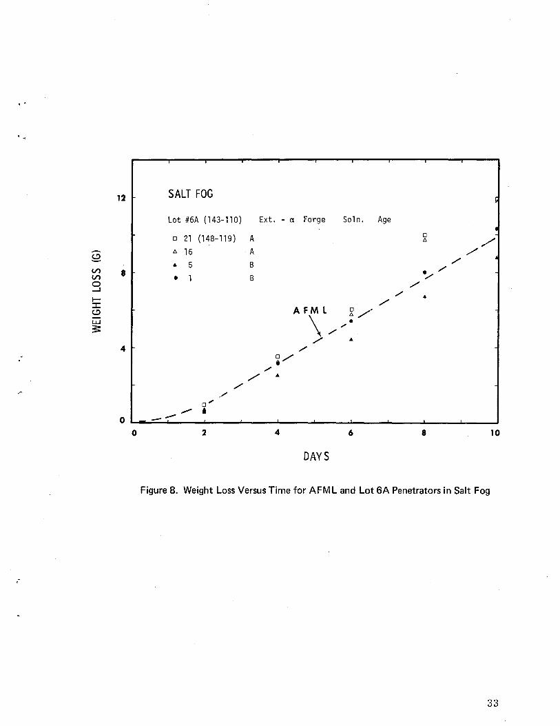
Figure 8 compares the corrosion response of penetrators from Lot 6A with the AFML material. It can be seen that the results from Lot 6A bracket the AFML curve. Again this result was expected in that material from Lot 6A was made similarily to the AFML material with only the ingot supplier being different. An analogous comparison is made in Figure 9 for penetrators from Lots 2 and 10e. These penetrators differ in metal processing from those discussed previously in that Lot 2 was j3-extruded and Lot 10e was 'V-extruded. They all were subsequently cold worked (swaged or forged), solutionized, aged, and ground. As seen in Figure 9, the corrosion response again bracketed the AFML standard. Figure 10 is a compilation of the test results from all the penetrators salt fog tested in Test Series II. The bracket obtained for Test Series II is almost identical to that obtained and previously described for Test Series I. The total spread from the least to the most corroded samples was only a factor of two. The penetrators manufactured by the various routes in this production plan all exhibited essentially the same corrosion response, and thus no selection of procedure can be made using corrosion response from salt fog tests as a guideline.
The good reproducibility of the corrosion response for penetrators from a given lot as tested in moist nitrogen is shown in Figure 11. These five penetrators represented the largest number tested from anyone lot. The highest and lowest weight loss varied from the average by only eight percent; a very small variation in response of uranium alloy material to corrosion in moist nitrogen. As discussed in the moist nitrogen testing of Series I penetrators, the shape of the curve suggests the formation of an inner, protective layer which retards the corrosion reaction with time.
30

.-
TABLE V
PRODUCTION PLAN: TEST SERIES II
NMI
(1) Extrude 1310°F, swage, and grind
(2) Extrude 1310°F, swage, solution treat, a age, b grind to Rc 44/48
(3A) Extrude 1310°F, solution treat, swage to Rc 41/48, and grind
(3B)C Extrude 1310°F, solution treat, swage to Rc 41/48, and grind
(3C) Extrude 1310°F, solution treat, swage to Rc 41/48, and grind; Omark thermal age and O. Q. d to Rc 44-51, and grind
(4A) Extrude high-carbon material (NMIB-1, -2), swage, solution treat, age to Rc 44/48. and grind
(4B)c Extrude high-carbon material (NMIB-1, -2), swage, solution treat, age to Rc 44/48, and grind
Omark a-extruded ELO-CVC (No.4. 3 inch c/»
(5) Forge and grind
(6A) Forge, solution treat, age to Rc 44/48, and grind
(6B)c Forge, solution treat, age to Rc 44/48, and grind
(7) Forge Rod 128, solution treat, age to Rc 44/48, and grind
(8) Solution treat, forge, age to Rc 44/48 (or maximum), and grind
(9) Forge bar ends (front and back), solution treat, age to Rc 44/48, and grind
Y-extruded ELO-CVC - Use rod from 7. 95 inch billets
(lOA) Forge and grind
(10B)C Forge and grind
(10C) Y-extrude; forge, solution treat, age to Rc 44/48, and grind
NLO a-extruded material
(11) Forge, solution treat, age to Rc 44/48, and grind
aSolution treat: minimum 5 minutes at 1475 to 1550°F
b Age: 700 to 850°F - higher temperature, shorter time preferred
cSeries B are for encapsulation, corrosion testing, and fire testing
dO. Q. - oil quench
31

12 SALT FOG
Lot 11 (150-121) Ext. - CI. Forge Soln. Age ~
• 5 A I
,/ • 6 B ,/
(.!) o 11 A ,,/' • V) 8
0/ • V)
"'" 0 /' -' /' I- / ::c A FM L ./ (.!)
~,/ I...L.J ~ $:
4 /' /'
/ /~ /
/' /
..-/ . ----0 --
0 2 4 6 8 10
DAYS
Figure 7. Weight Loss Versus Time for AFM L and Lot 11 Penetrators in Salt Fog
-.
32
..
Vl Vl g I:::c c.!)
LLJ
s:
12
8
4
SALT FOG
Lot #6A (143-110)
o 21 (148-119) t:. 16
.. 5
• 1
/'"
o --o 2
Ext. - ct Forge
A
A
B
B
~,/ ,/
,/ ..
4
,/
DAYS
So1n. Age
/'"
6
. ,/ /'
8 10
Figure 8. Weight Loss Versus Time for AFML and Lot 6A Penetrators in Salt Fog
33

, ,
(
12 SALT FOG ~
Lot #2 Lot #10C (151 - 122) • Ext. - R· Swage Ext. - ex Forge
• 27 A • 13 A i /' ~ /' [
& 33 B D. 16 A C.!) /' ( o 2362 A • 6 B ./' V) 8 V) 0 40 B 0 11 A ,/' 0 ......J
/' 0 D. 0 l- e /' :c
C.!) A FM L /' L.LJ
~ :s: /" 8
4 t/ /8
/ ./'
......... /t/
0 -~
0 2 4 6 8 10 ..
DAYS
. Figure 9. Weight Loss Versus Time for AFM L and Lots 2 and 1 DC Penetrators in Salt Fog
-.
34

· .
,-
12
V') 8 V')
g I:::c <.!)
l.LJ
s: 4
o
SALT FOG
olot with highest rate
.lot with lowest rate
2 4 6 8 10
DAYS
Figure 10. Compilation of Weight Loss Data for Penetrators in Test Series' II
35

, .
150 MO 1ST N ITROG EN • • § • Q ! 0 el 0 • • •
0 ! • 0 • D.
<.!) ~ • :2i: 0 D.
(./') 100 !!! (./')
g I-:J: <.!)
LOT #5 Ext. - a Forge l..LJ
:s: 50 0 143 - 111 1Q B
0 145 - 115 6 B D. 145 - 115 12 A
• P1
• P2
0
0 8 16 24 32
DAYS
Figure 11. Weight Loss Versus Time for Lot 5, Test Series II, in Moist Nitrogen
-.
36

:
The corrosion response from this Lot 5 in Test Series II was similar to that observed for the analogous material tested in Test Series 1.
The final weight lost for each of the penetrators tested in moist nitrogen in Test Series II is tabulated in Table VI. There are some similarities between the data taken in Test Series I and II. First. material which had been either a- or f3-extruded. cold worked by either forging or swaging with no subsequent solutionizing nor aging treatment exhibited the largest weight losses. Thus penetrators from Lots 1 and 5 had final weight losses which were five to ten times larger than those of other penetrators. In contrast. the corrosion response of penetrators in Lot 10A. which had been v-extruded and forged with no subsequent heat treatments. was the smallest of any in Test Series II.
Secondly. the penetrators with a history similar to the AFML material (i. e.. a-extruded. forged or swaged. solutionized and aged) such as Lots 11 and 6A. gave very similar responses to Test Series I material. The corrosion response data for Lot 6A. shown in Figure 12. is additionally interesting in that while three penetrators made from one piece of bar stock showed identical corrosion behavior. their behavior differed from that of a fourth penetrator in this lot made from another piece of bar stock. This result suggests that there are metallurgical differences from bar to bar within the same lot.
Thirdly. the remaining lots within Test Series II had a corrosion response similar to each other and bracketing Lot 11. This result was expected in that these materials underwent a solution treatment and some an additional aging treatment. Thus differences in processing treatment in this category resulted in no difference in corrosion response. In summary. except for V-extruded material. solutionizing the material either before or after the cold working process does improve the resistance of the material toa moist nitrogen environment.
No stress corrosion cracking was observed in any of the Test Series II penetrators.
The encapsulated penetrators showed no signs that any swelling reaction took place. The changed appearance of the tarnish film on the penetrators was analogous to that discussed for the Test Series I penetrators. The penetrators that had been salt fog tested showed a darkened but adherent film. whereas those which had been tested in moist nitrogen had a film that was appreciably thicker and partially nonadherent. These results prove again that the encapsulation does not provide a hermetic seal.
37

TABLE VI
TEST SERIES II PENETRA TORS - MOIST NITROGEN RESULTS .. Lot SIN Condition WL * (g) Lot SIN Condition WL*,(g)
1 5 A 0.1929 6A 4 B 0.0100
1 6 A 0.1999 6A 24 A 0.0207
1 13 B 0.1810 6A 26 A 0.0207
6A 28 B 0.0208
2 7 A 0.0206
2 10 B 0.0352 7/9 6 A 0.0282
2 19 B 0.0183 7/9 18 A 0.0287
2 26 A 0.0055
8A 4 B 0.0305
3A 30 A 0.0464 8A 7 A 0.0279
3A 33 B 0.0278 8A 9 A 0.0236
3C 8 A 0.1967 9 15 A 0.0155
3C 18 B 0.0180 9 17 B 0.0087
4A 7 A 0.0088 lOA 14 A 0.0041
4A 10 B 0.0078 lOA 54 B +0.0006**
5 6 B 0.1489 10C 20 A 0.0252
5 10 B 0.1446 10C 23 B 0.0264
5 12 A 0.1252
5 P1 B 0.1467 11 8 B 0.0219
5 P2 B 0.1448 11 9 B 0.0216
11 12 A 0.0243
,', ','
WL - final weight loss -. ":<>:<
+ - weight gain
*A - Acceptable surface condition
*B - Unacceptable surface condition
38

30 MOl ST NITROGEN 0 143 - 110 24A
0 143 - 110 26A Lot #6A .. 143 - 11 0 28B Ext. - y Forge Soln . Age
~ • 148 - 119 4B
• V) 20 0 V) ~
.. 0 0 ~ 0 ....J ..
0
t- o :J: 0
c.!:)
l..L.J ~
10 • • • • • •
.
0 "
0 8 16 24 32
DAYS
Figure 12. Weight Loss Versus Time for Lot 6A, Test Series II, in Moist Nitrogen
39

e oated Penetrators
A few penetrators were selected from each lot of Test Series II and coated with electroplated nickel plus electroplated zinc and zinc chromate finishes. (See appendix for plating details.) No difficulty was encountered in applying the coating. The only corrosion observed on the coated units, which was barely measurable. was the slight oxidation of the zinc overlayer to a powdery. white zinc oxide tarnish film. Therefore, the coating protected all the penetrators very well.
Rod Samples
The primary purpose in testing pieces of rod in the as-extruded condition was to observe the material for any propensity to see in this nonstress relieved state. The possibility for see in the manufacturing process, if the material is susceptible to see, is high in that long delays between· extrusion and cold working. and! or cold working and solutionizing are possible.
Tables VII and VIII list the material processors. the billet sizes. and the extrusion conditions used for obtaining the rods tested in both salt fog and moist nitrogen. The four-inch lengths of rod were tested in the asreceived condition. There was no indication of see in any of the rods after either salt fog or moist nitrogen testing. Figure 13 shows a compilation of the weight loss data for the rods tested in salt fog. In agreement with the results from Test Series I and II. the total spread in corrosion response was less than a factor of two. Table VII shows that the primary reason for this spread was the difference in corrosion response between a- and '(extruded rod. One interesting point extracted from the data of Table VII is that NLO material which is subsequently extruded at RMI is more cor-· rosion resistant than analogously extruded material made at ELO. This pattern holds true for both a- and ,(-extruded material. The /3-extruded material from NMI corroded similarily to the best '( -extruded material from NLO. Increasing the carbon content did have a significant detrimental effect on the corrosion resistance of this material. as seen in Lot 5B.
Examining the results listed in Table VIII for moist nitrogen testing of this rod material indicates an almost complete reversal of the patterns just described. The a-extruded material is more corrosion resistant than the '( -extruded material. and the ELO material is more corrosion resistant than the analogous NLO material. Also. increasing the carbon content in NMI material did not change the corrosion response. The best conclusion from these observations is that the rank order of material by corrosion response is a strong function of the test environment when the corrosion response is very similar.
40
",

TABLE VII
ROD SAMPLES - SALT FOG TEST
SIN Processor Extrusion Condition Billet Size WL *(g)
. , 27-1 NMI [3 - extru d ed Standard product 15.47
27-2 " " " 16.71
5B-l NMI [3-extruded High-carbon 21. 75
5B-2 " " " 21. 37
158-3 ELO a-extruded 5.1 eve 19.01
158-4 " " " 19.98
138-1 ELO a-extruded 5.1 DF 25.07
138-2 If If If
22.63
239-1 ELO V-extruded 7.95 eve 20.16
239-2 If If If
19.94
247-1 ELO V-extruded 7.95 DF 20.48
247-2 If If " 19.85
149-1 NLO a-extruded 5. 1 19. 13
149-2 " If " 18.67 .' 244-1 NLO V-extruded 7.95 14.88
244-2 If " " 16.20
* W L - final weight los s
-.
41

TABLE VIII
ROD SAMPLES - MOIST NITROGEN TEST
SiN Processor Extrusion Condition Billet Size WL *(g)
27-3 NMI {3-extruded Standard product 0.061
27-4 " " " 0.087
5B-3 NMI {3-extruded High carbon. 0.064
5B-4 " " " 0.088
158-1 ELO a-extruded 5.1 eve 0.027
158-2 " " " 0.032
138-3 ELO a-extruded 5.1 DF 0,041
138-4 " " " 0.057
239-3 ELO 'V-extruded 7.95 eve 0.034
239-4 " " " 0.047
247-3 ELO 'V -extruded 7.95 DF 0.062
247-4 " " " 0.084
149-3 NLO a-extruded 5.1 0.072
149-4 " " " 0.067
244-3 NLO 'V-extruded 7.95 0.111
244-4 " " " 0.058
):<W L - final weight loss
42

.. ,
g V') V')
0 .....J
I-::c C,!)
~ 5:
30 SALT FOG
20
10
o ~.~ 0
o
Extruded Rod
• 138 #1 • 138 #2
l> 244 #24-1 o 244 #24-2
4
Ext. - Cl •
Ext. - y
8 12 16
DAYS
Figure 13. Compilation of Weight Loss Data for Rod Samples in Salt Fog
43

Cold Straightened Penetrators
The primary purpose in testing penetrators which had been cold straightened to meet inspection specifications was to observe any propensity to SCC in this nonstress relieved material. Twelve penetrators were produced per Lot 6 requirements of Test ·Series II which·were significantly out of specification before cold straightening. Six were selected for moist nitrogen testing and six for salt fog. No evidence of SCC was seen on any of these penetrators after testing. Figure 14 is a plot of weight loss versus time for the six tested in salt fog. This data is given to primarily show the good reproducibility in corrosion response when the penetrators are "identical." The variation in the highest and lowest rate from the average is only five percent. which is a very small variation for response to corrosion.
Encapsulated. Corrosion Tested. and Fire Tested
Twenty penetrators each were taken from Lots 3B. 4B. 6B. and lOB (Table V). encapsulated at AOMC. corrosion tested in a salt fog environment at SLL. and fire tested at AOMC. The ballistic results from these penetrators were no different than the results from similarly prepared penetrators which had not undergone the exposure to a corrosive environment. Thus. the slight increase in the oxide tarnish film thickness due to the environmental exposure had no effect on ballistic performance.
Summary
The most important result from this study was that no penetrator tested showed any evidence of SCC. Thus no chemistry nor metal processing variable examined caused the uranium-titanium alloy to be more susceptible to stress corrosion cracking than "standard" material. Secondly. the largest difference in corrosion response to the salt fog environment between any two lots of material was a factor of two. The material with the highest corrosion rate had been a-extruded and forged with no subsequent solutionizing nor aging treatment. and it also had an extremely high carbon content. The material with the lowest corrosion rate had been {3-extruded and swaged, solutionized but not aged, and composed of nominal chemistry.
Somewhat different results were obtained from moist nitrogen testing. In this case the most corrosion susceptible material had been either a- or {3-extruded. cold worked by either forging or swaging, no subsequent solutionizing nor aging treatment. and composed of nominal chemistry. The analogously prepared material with high carbon content was significantly more corrosion resistant. The material with the lowest corrosion rate in
44

lS SALT FOG Cold Straightened Penetrators Lot #6 Ext. - a Forge Soln. Age ~ 0 25
i
6 29 S2
0 Ii V')
10 V') • 21 ~ 0 • -' • 1 6
I-:c • 20 C,!)
~ I.LJ
:5: • S
.- o ~ __ ~~ __ ~~ __ ~ ____ ~ ____ ~ ____ ~ ____ ~ ____ ~ ____ ~ ____ ~ o 2 4 6 8 10
DAYS
Figure 14. Response to Salt Fog of Cold Straightened Penetrators
45
moist nitrogen had been y-extruded and forged with no subsequent heat treatments. The difference in the final weight lost between the most and least corroded material was a factor of ten. In that the weight loss for even the most susceptible was very small, these differences are indeed small. The differences in the corrosion rates from lot to lot are even smaller than the final weight loss projects, since the weight loss curves versus time approach flatness after a few days of test time.
The coating of electroplated nickel plus electroplated zinc with a zinc chromate finish performed extremely well on all the penetrators coated and corrosion tested.
Cold straightened penetrators did not show any evidence of SCC after corrosion testing, and their corrosion response was analogous to those previously tested from the same lot.
Pieces of rod tested in the as -extruded conditions had corrosion responses similar to the analogously treated penetrators. They' also did not show any signs of a propensity to SCC.
Encapsulation did provide some protection of the penetrator from the test environment. However, the encapsulation does not provide a hermetic seal, and thus the external environment does communicate with the penetrator. The communication of the salt fog with the penetrator in the encapsulant with subsequent thickening of the oxide tarnish film did not produce a change in the ballistic response of the penetrator.
Conclusions
The primary conclusion from this study is that no variations in the uranium-titanium chemistry nor in the route or technique of metal processing examined caused a change of practical significance in the corrosion response of the material as tested in either salt fog or moist nitrogen. Therefore, the data assembled for corrosion response of the various lots cannot be used in selecting one lot over another. In the context of this study, all the material performed in an identical manner.
Secondly, the penetrators could be coated without difficulty in spite of changes in material chemistry and the metal processing route.
The combined encapsulation, corrosion, and fire tests indicated that a coating system to protect the penetrators during long-term storage is not necessary.
46
'.

· .
l.
2.
3.
4.
5.
6.
7.
B.
u 9.
10.
ll.
12.
13.
14.
15.
16.
17.
lB.
APPENDIX
ETCHING AND PLATING PROCEDURES
Vapor degrease in trichloroethylene
Caustic soak for 5 minutes at 70° to BO°C
Water rinse
Scrub surfaces with pumice
Water rinse
Pickle in 35 percent (by weight) solution of nitric acid at room temperature for 2 minutes
Water rinse
Etch in 1400 gIl ferric chloride solution for 10-15 minutes at 49°C
Water rinse
Pickle in 35 percent (by weight) solution of nitric acid at room temperature for 2 minutes
Water rinse
Caustic soak for 5 minutes at 70° to BO°C
Water rinse
Pickle in 35 percent (by weight) solution of nitric acid at room temperature for 2 minutes
Water rinse
Plate in nickel sulfamate solution
Plate in zinc cyanide solution
Chromate in Granodine 90
47

(Solution Composition and Operating Conditions)
Nickel Sulfamate Solution
Nickel sulfamate
Boric Acid
Surface Tension
pH
Temperature
Anodes
Filtration
Current Density
450 gil
30 gil
34-38 dyneslcm
3.8-4.0
48 to 50°C
sulfur depolarized nickel
continuous
270 A/m2
(Solution Composition and Operating Conditions for Zinc Plating and Chromating)
Cyanide Zinc Solution
Zinc
Sodium Cyanide
Sodium Hydroxide
Cyanide I Zinc Ratio
Temperature
Current Density
Chromate
Granodine 90*
>'.<
22.5 gil
56.5 g/1
80.0 gil
2. 5/1
22°C
270 A/m2
10% by volume
Product of Amchem Products, Inc., Ambler, PA.
48
,.

REFERENCES
1. S. Orman, "Oxidation of Uranium and Uranium Alloys, " Physical Metallurgy of Uranium Alloys·, J. J. Burke, D. A. Colling, A. E. Gorum, and J. Greenspan (eds.), Brook Hill Publishing Company, Chestnut Hill, MA, 1976.
2. L. J. Weirick, H. R. Johnson, and J. W. Dini, Corrosion and Protection of Uranium Alloy Penetrators, Sandia Laboratories, Livermore, SAND75-8243, June 1975.
3. L. J. Weirick, "Protective Coatings for Uranium Alloys, " Physical Metallurgy of Uranium Alloys, J. J. Burke, D. A. Colling, A. E. Gorum, and J. Greenspan, (eds.), Brook Hill Publishing Company, Chestnut Hill, MA, 1976.
4. L. J. Weirick, Evaluation of Metallic Coatin s for the Corrosion Protection of a Uranium-3 4 Weight Percent Titanium Alloy, Sandia Laboratories, Livermore, SLL-73-5024, January 1974.
5. H. R. Johnson and J. W. Dini, Protective Coating Studies for the W75 Program, Sandia Laboratories, Livermore, SLL-73-0058, October 1973.
6. L. J. Weirick and D. L. Douglass, "The Effect of Thin Electrodeposited Nickel Coatings on the Corrosion Behavior of U-O. 75 Ti, " CORROSION, 32, No.6, June 1976, pp. 209-216.
7. A. L. Hoffmanner and G. H. Meyer, Chemistry and Metal Processin Study for the General Electric Manufacturing Technology GAU 8 A Penetrator Program, Battelle Memorial Institute, Columbus, Ohio, to be published.
8. N. M. Weare, Extrusion and Swaging Processes for the General Electric Manufacturing Technology GAU 8/ A Penetrator Program, Nuclear Metals, Inc., Concord, MA, to be published.
9. N. F. Brewer, Extrusion Parameters for the General Electric Manufacturing Technology GAU 8/ A Penetrator Program, Reactive Metals, Inc., Ashtabula, Ohio, to be published.
49

10. D. G. Spring, Forging and Grindin Processes for the General Electric Manufacturing Technology GAU 8 A Penetrator Program, Omark Industries, El Segundo, California, to be published.
11. N. J. Magnani, "Stress Corrosion Cracking of Uranium Alloys, " Physical Metallurgy of Uranium Alloys, J. J. Burke, D. A. Colling, A. E. Gorum, and J. Greenspan (eds. ), Brook Hill Publishing Company, Chestnut Hill, MA, 1976.
12. C. A. Colmenares, D. R. McKenzie, and T. E. Shell, "MultipleSpecimen Thermogravimetric Gas - Flow Apparatus for Oxidation Studies, "J. of PHYSICS E: SCIENTIFIC INSTRUMENTS, 6, p. 1121, 1973.
13. L. A. West, "Relative Sputtering Yields and Quantitative Surface Analysis by Auger Spectroscopy, " J. VAC. SCI. TECHNOL, 13, No.1, January/February 1976.
14. M. McD. Baker, L. N. Less, and S. Orman, "Uranium + Water Reaction: Part 1. Kinetics, Products, and Mechanism, " TRANS. FARADAY SOC, 62, pp. 2513-54, 1966.
15. L. J. Weirick, unpublished research work, 1976.
50

< '
••
('
UNLIMITED RELEASE
INITIAL DISTRIBUTION
U. S. Energy Research & Development Administration Albuquerque Operations Office Branch Special Programs Division Reimbursable Activities Albuquerque, NM 87115 Attn: J. R. Cotton, Chief
H. N. Hill, Director R. R. Malone, Chief
Wright-Patterson Air Force Base Ohio 45433 Attn: S. Inouye
F. H. Meyer Dr. C. T. Lynch
Eglin Air Force Base Florida 32542 Attn: J. Jenus, Jr.
A. Lopez
Headquarters U. S. Air Force Washington, D. C. 20330 Attn: Major D. E. Spongberg
Andrews Air Force Base Washington, D. C. 20334 Attn: R. W. Hartmeyer
Air University Library Maxwell Air Force Base Alabama 36112
Deputy Chief of Staff for Operations U. S. Army Washington. D. C. 20330 Attn: Major Ramsey
Army Materiel Command 5001 Eisenhower Avenue Alexandria, VA 22333 Attn: Capt. G. Tonn
ERDA-SAO ERDA-ALO ERDA-SAO
AFML/LTM AFML/MXA AFML/LLN
AFATL/DLDA AFATL/DLOU
ASAF/RDRI
AFSC/SDW
DAMO-RQD
AMCRD-EA
51

Army Materials and Mechanics Research Center
Watertown. MA 02172 Attn: Dr. F. Larson
M. Levy
Frankford Arsenal Bridge and Tacony Street Philadelphia. PA 19137 Attn: R. E. Edelman
Pica tinny Arsenal Dover, NJ 07801 Attn: R. P. Davitt (2)
Lake City Army Ammunition Plant Independence, MI 64056 Attn: E. Knight
Naval Ordnance System Command Washington, D. C. 20360 Attn: Mr. B. Tabb
SEA Systems Command Washington, D. C. 20362 Attn: B. B. Rosenbaum
Naval Weapons Laboratory Dahlgren, VA 22448 Attn: Dr. S. G. Fishman
Defense Documentation Center Alexandria, VA 22314 (2)
AAI Corporation Cockeysville, MD 21030 Attn: M. M. Rottenberg
Aeroj et Ordnance & Manufacturing Company 9236 East Hall Road Downey, CA 90241 Attn: J. J. Joyce
A erospace Corporation 2350 East El Segundo El Segundo. CA 90245 Attn: Dr. E. G. Kendall
52
AMMRC-Bldg. 312 Metals Research Division
Pitman-Dunn Laboratory
SARPA-AD-D-A-2
Army Technology Division Remington Arms Company
ORD 55-20B
Code 03523
GWR

..
, ..
•
Amron Corporation P. O. Box 47 525 Progress Avenue Waukesha, WI 53186
Battelle Northwest Richland. WA 99352 Attn: R. S. Kemper
G. E. Zima
Battelle Columbus Laboratories 505 King Avenue Columbus. OH 43201 Attn: Dr. A. Hoffmanner
Dr. G. A. Meyer
Eldorado Nuclear Limited 215 John Street Port Hope. Ontario, Canada LIA 3A1 Attn: Dr. R. Barclay
General Electric Company Lakeside Avenue Burlington. VT 05401 Attn: R. A. Schell (5)
F. Adamske
Honeywell. Inc. Government & Aeronautical Division New Birghton, MN 55112 Attn: A. M. House
M. Williams F. Lerner
National Lead Company of Ohio P. O. Box 39158 Cincinnati, OH 45239 Attn: L. M. Levy
C. E. Polson
N. L. Industries 1130 Central Avenue Albany, NY 12205 Attn: H. M. Drucker
N2540 N2540 N2540
53

Nuclear Metals, Inc. 2229 Main Street Concord, MA 01742 Attn: P. Loewnstein
N. E. Weare
Omark Industries 1415 East Grand Avenue El Segundo, CA 90245 Attn: D. G. Spring
R MI Company Extrusion Plant P. O. Box 579 Astabula, OR 44004 Attn: N. F. Brewer
Atomic Weapons Research Establishment Building A2. 2 Aldermaston, Reading RG7 4PR ENGLAND Attn: C. Calow
S. Antony G. Picton B. Ward A. Kay
Los Alamos Scientific Laboratory P. O. Box 1663 Los Alamos, NM 87544 Attn: D. J. Sandstrom
Union Carbide Corporation Nuclear Division Y-12 Plant Records Dept., Bldg. 9711-5 P. O. Box Y Oak Ridge. TN 37830 Attn: J. Koger
G. L. Powell J. S. Bullock, IV W. Tewes
Rockwell International Atomic International Division R ocky Flats Plant Golden, CO 80401 Attn: R. Krenzer
R. Mah
54
..

.. t •
• •
•
C. A. Colmenares. LLL. L460 L. W. Roberts. LLL. L426 D.H. Wood. LLL. L426
R. S. Claassen. 5800: Attn:. R. G. Kepler. 5810
M. J. Davis. 5830 N. J. Magnani. 5831 S. L. Pohlman. 5831
R. L. Schwoebel. 5820 H. J. Saxton. 5840
T. B. Cook. Jr •• 8000; Attn: C. H. DeSelm. 8200 W. C. Scrivner. 8400
L. Gutierrez, 8100 D. E. Gregson. 8150 G. N. Beeler. 8157; Attn: H. Hanser R. D. Cozine. 8160 D. J. Bohrer. 8167 B. F. Murphey. 8300; Attn: T. S. Gold. 8320
D. M. Schuster, 8310 D. R. Adolphson, 8312 J. W. Dini, 8312 H. R. Johnson. 8312 M. W. Mote. 8312 K. A. Pashman. 8312 L. J. Weirick. 8312 (15) R. W. Mar. 8313 C. W. Schoenfelder. 8313 D. B. Dawson. 8314 A. J. West. 8314 W. R. Hoover. 8314
G. W. Anderson. 8330 J. L. Wirth, 8340 J. F. Barham. 8360
Technical Publications and Art Division. 8265. for TIC (2) F. J. CuPps. 8265/Technical Library Processes Division. 3141 Technical Library Processes Division. 3141 (2) Library and Security Classification Division. 8266 -2 (3)
55/56