counting scale - aandd.jp · fc-i counting scale: 1/1,000,000 fc-si counting scale: up to...
TRANSCRIPT

ふ
Counting Scale FC-50Ki FC-5000Si FC-20Ki FC-500Si FC-10Ki FC-5000i FC-2000i FC-1000i FC-500i
WM+PD4000541B

This manual and Marks All safety messages are identified by the following, “WARNING” or “CAUTION”, of ANSI
Z535.4 (American National Standard Institute: Product Safety Signs and Labels). The meanings are as follows:
WARNING A potentially hazardous situation which, if not avoided, could result in death or serious injury.
CAUTION A potentially hazardous situation which, if not avoided, may result in minor or moderate injury.
This is a hazard alert mark. This mark informs you about the operation of the product. The information mark of other operations. Note This manual is subject to change without notice at any time to improve the product. No
part of this manual may be photocopied, reproduced, or translated into another language without the prior written consent of the A&D Company.
Product specifications are subject to change without any obligation on the part of the
manufacture. Compliance with FCC rules Please note that this equipment generates, uses and can radiate radio frequency energy.
This equipment has been tested and has been found to comply with the limits of a Class A computing device pursuant to Subpart J of Part 15 of FCC rules. These rules are designed to provide reasonable protection against interference when this equipment is operated in a commercial environment. If this unit is operated in a residential area it might cause some interference and under these circumstances the user would be required to take, at his own expense, whatever measures are necessary to eliminate the interference.
(FCC = Federal Communications Commission in the U.S.A.)
Copyright 2003
Contents
1. INTRODUCTION ...........................................................................................................3 1-1. Introduction.............................................................................................................................. 3 1-2. Unpacking ............................................................................................................................... 4 1-3. Setting Up Your Scale ............................................................................................................. 5 1-4. Standby and Operating Mode.................................................................................................. 7 1-5. Simple Operation Mode........................................................................................................... 7 1-6. kg or lb Weighing Units ........................................................................................................... 7 1-7. Last Unit Weight Used Feature ............................................................................................... 8
2. FRONT PANEL OVERVIEW .........................................................................................9
3. BASIC OPERATIONS .................................................................................................10 3-1. Basic Operations ................................................................................................................... 10 3-2. To Start Counting................................................................................................................... 12 3-3. Unit Weight By Samples........................................................................................................ 13 3-4. Unit Weight By KEYBOARD.................................................................................................. 17 3-5. Unit Weight By ID Number .................................................................................................... 18
4. ENTERING A TARE WEIGHT .....................................................................................19 4-1. Using the KEYBOARD TARE Key......................................................................................... 19 4-2. To Clear TARE....................................................................................................................... 20
5. STORE UNIT WEIGHT................................................................................................21 5-1. Store Unit Weight by ID Number ........................................................................................... 21 5-2. Clearing A Stored Unit Weight ............................................................................................... 22 5-3. Store Item Code by ID Number ............................................................................................. 23 5-4. Unit Weight, Tare, Comparator Limits & Total Count Stored ........................................................... 25
6. USING THE M+ MEMORY ..........................................................................................26 6-1. The M+ Memory Function ..................................................................................................... 26 6-2. Viewing the M+ Total ............................................................................................................. 27 6-3. Clearing the M+ Total ............................................................................................................ 27 6-4. The M- Function .................................................................................................................... 27
7. COMPARATOR FUNCTION........................................................................................28
8. TIME AND DATE FUNCTION......................................................................................30
9. CALIBRATION ............................................................................................................31
1 ©A&D Co.ltd., FC-i Instruction manual International version 23783AIE0309

9-1. Calibration Procedure Using a Weight .................................................................................. 31 9-2. Gravity Compensation........................................................................................................... 33
10. F-FUNCTION PARAMETERS....................................................................................34 10-1. To Change or View F-Function Settings............................................................................. 34 10-2. F-Functions ........................................................................................................................ 36
11. ACAI FUNCTION .......................................................................................................44 11-1. ACAI Automatic Counting Accuracy Improvement ........................................................ 44 11-2. ACAI Automatic Operation ................................................................................................. 44 11-3. ACAI Manual Operation ..................................................................................................... 45
12. RS-232C SERIAL INTERFACE .................................................................................46 12-1. RS-232C Specifications ..................................................................................................... 46 12-2. Data Output Mode.............................................................................................................. 47 12-3. Connecting the AD-8121 Printer / MODE 1 or MODE 2..................................................... 48 12-4. Connecting the AD-8121 Printer / MODE 3........................................................................ 49 12-5. Command Mode ................................................................................................................ 50 12-6. Using a Bar Code Reader.................................................................................................. 55 12-7. Using UFC (Universal Flex Coms) Function ...................................................................... 59
13. OPTIONS ...................................................................................................................62 13-1. OP-01 Bar Code Reader.................................................................................................... 62 13-2. OP-02 Ni-MH Battery Pack ................................................................................................ 65 13-3. OP-03 2 Ch. RS-232C ....................................................................................................... 67 13-4. OP-04 RS-232C and Comparator Relay Output ................................................................ 68 13-5. OP-05 Remote Scale Interface .......................................................................................... 69
14. SPECIFICATIONS .....................................................................................................73 14-1. Dimensions ........................................................................................................................ 75
15. GRAVITY ACCELERATION MAP..............................................................................76
16. INDEX ........................................................................................................................78
2

1. INTRODUCTION
1-1. Introduction
Thank you for your Purchase!
This manual describes the functions of your counting scale and how to get the most out of it. Read this manual carefully before use.
Features
The FC-i / FC-Si counting scales have the following features:
The scales have the following high internal resolution for a wider range of counting applications.
FC-i counting scale: 1/1,000,000 FC-Si counting scale: Up to 1/10,000,000
There are the following ways to enter a unit weight (of the sample piece).
The way to weigh a fixed number of samples like 5 pieces, 10 pieces and so on. The way to weigh the desired number of samples. The way to store the desired unit weight directly using the 10-key pad. The way to recall the stored unit weight from ID memory. The way to send the desired unit weight from a personal computer. The way to use a bar code reader to designate an ID number to enter the unit weight directly.
Three UNIT WEIGHT BY LED's will navigate you to store a unit weight easily.
ACAI (Automatic Counting Accuracy Improvement) supports counting by recalculating the unit weight when a sample is added. Therefore it is possible to reduce the counting error.
The scale has a large bright vacuum fluorescent display and can show information for piece count, weight, unit weight, ID number, item code and comparator result at the same time.
UP to 500 ID memories can store 6 digits ID numbers, consisting of 12 digit item code (alphanumeric), unit weight, tare weight and comparator limits.
Comparator function:
Compare a count or weight Comparator limits can be changed temporarily using the 10-key pad. Comparator relay output is also available using an optional interface.
Accumulation function for counting.
Standard RS-232C interface and optional interfaces (up to 3 ch. RS-232C available) to communicate with a personal computer, printer and bar code reader expanding the counting application.
A two-scale counting system can be constructed using the optional a remote scale interface and remote platform.
3
It is possible to send the time and date to a computer connected to the RS-232C interface using the scale's built-in clock.
The optional rechargeable battery pack (Ni-MH) is useful for portable operation.
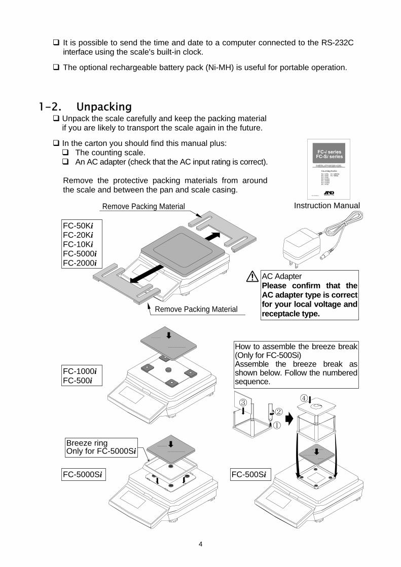
1-2. Unpacking Unpack the scale carefully and keep the packing material if you are likely to transport the scale again in the future.
In the carton you should find this manual plus:
The counting scale. An AC adapter (check that the AC input rating is correct).
Remove the protective packing materials from around the scale and between the pan and scale casing.
Remove Packing Material
Instruction Manual
AC Adapter Please confirm that the AC adapter type is correct for your local voltage and receptacle type.
FC-500Si
FC-1000i FC-500i
FC-50Ki FC-20Ki FC-10Ki FC-5000i FC-2000i
FC-5000Si
Remove Packing Material
Breeze ring Only for FC-5000Si
How to assemble the breeze break (Only for FC-500Si) Assemble the breeze break as shown below. Follow the numbered sequence.
4
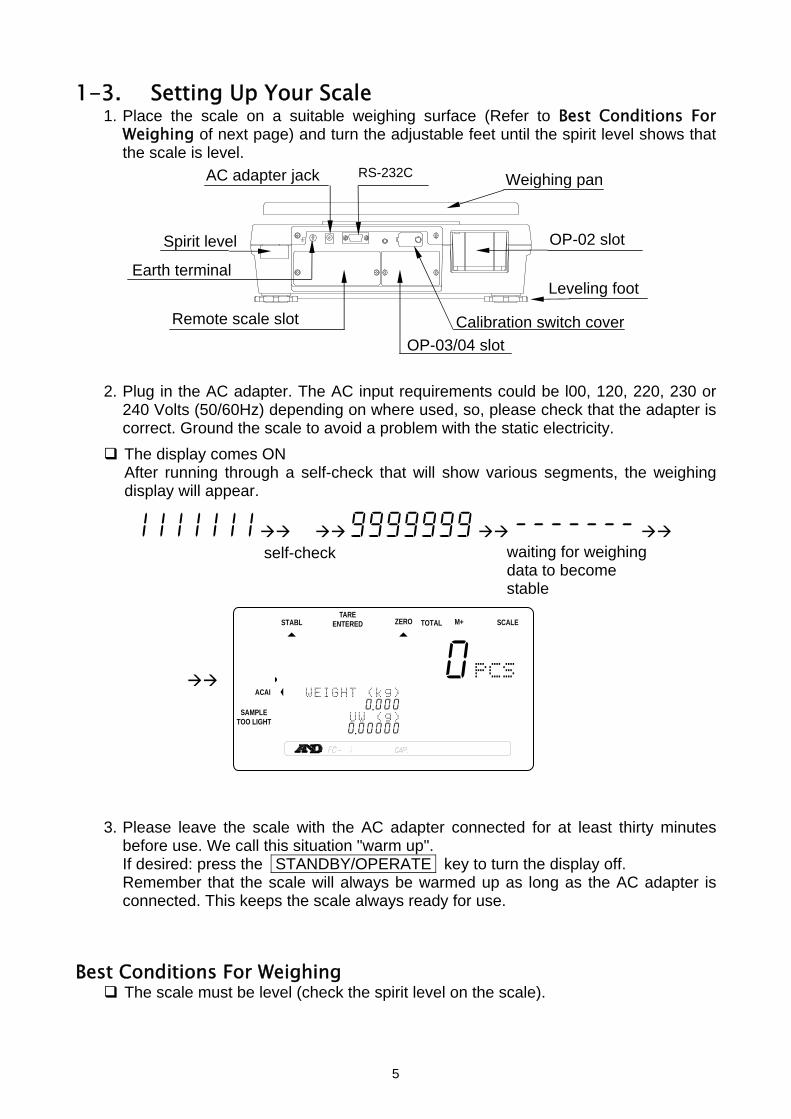
1-3. Setting Up Your Scale 1. Place the scale on a suitable weighing surface (Refer to Best Conditions For
Weighing of next page) and turn the adjustable feet until the spirit level shows that the scale is level.
2. Plug in the AC adapter. The AC input requirements could be l00, 120, 220, 230 or 240 Volts (50/60Hz) depending on where used, so, please check that the adapter is correct. Ground the scale to avoid a problem with the static electricity.
The display comes ON After running through a self-check that will show various segments, the weighing
display will appear.
1111111 9999999 ------- self-check
3. Please leave the scale with the AC adapter connected for at least thirty minutes before use. We call this situation "warm up". If desired: press the STANDBY/OPERATE key to turn the display off. Remember that the scale will always be warmed up as long as the AC adapter is connected. This keeps the scale always ready for use.
Best Conditions For Weighing
The scale must be level (check the spirit level on the scale).
waiting for weighing data to become stable
STABL
.8888880881pcs
W WEIGHT (kg) 12134567890 .000 234A56UUW (g)
123145670 .00000
ZERO TOTAL M+ TARE
ENTERED SCALE
ACAI
SAMPLE TOO LIGHT
Spirit level
Leveling foot Earth terminal
Weighing pan
Remote scale slot
AC adapter jack
OP-02 slot
OP-03/04 slotCalibration switch cover
RS-232C
5

Best operating temperature is between 20°C~25°C / 68°F~77°F at about 50%~60% relative humidity. There shouldn’t be large temperature fluctuations.
The weighing room should be kept clean and dry.
The weighing table must be of a solid construction.
Corners of rooms are best as they are less prone to vibrations.
Don’t install the scale near heaters or air conditioners.
Don’t install the scale in direct sunshine.
Try to ensure a stable AC power supply when using the AC adapter.
Keep equipment containing magnets away from the scale.
Warm up the scale before use or leave it on standby overnight.
Ground the scale chassis for electrostatic discharge if the weighing conditions warrant.
Calibration
Calibration of the scale is required when the scale is initially installed, or if a remote scale is added. Please refer to “9. CALIBRATION” for more calibration information.
6
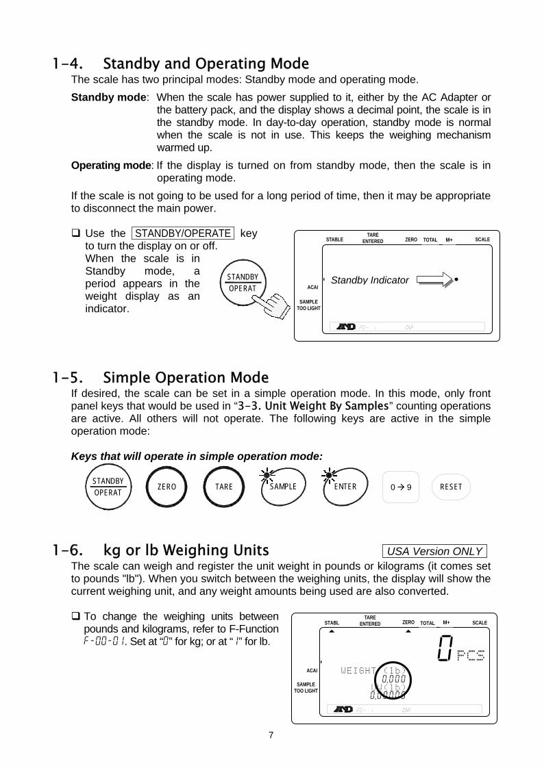
1-4. Standby and Operating Mode The scale has two principal modes: Standby mode and operating mode.
Standby mode: When the scale has power supplied to it, either by the AC Adapter or the battery pack, and the display shows a decimal point, the scale is in the standby mode. In day-to-day operation, standby mode is normal when the scale is not in use. This keeps the weighing mechanism warmed up.
Operating mode: If the display is turned on from standby mode, then the scale is in operating mode.
If the scale is not going to be used for a long period of time, then it may be appropriate to disconnect the main power.
Use the STANDBY/OPERATE key to turn the display on or off.
When the scale is in Standby mode, a period appears in the weight display as an indicator.
1-5.
1-6.
Simple Operation Mode If desired, the scale can be set in a simple operation mode. In this mode, only front panel keys that would be used in “3-3. Unit Weight By Samples” counting operations are active. All others will not operate. The following keys are active in the simple operation mode: Keys that will operate in simple operation mode:
kg or lb Weighing Units The scale can weigh and register the unit weight in pounds or kto pounds "lb"). When you switch between the weighing units, thecurrent weighing unit, and any weight amounts being used are al
To change the weighing units between pounds and kilograms, refer to F-Function f-00-01. Set at “0” for kg; or at “1” for lb.
STABL
.8888W WEIGHT
112345678902A3456UUW
123145670 .0
TARE ENTERED
ACAI
SAMPLE TOO LIGHT
OPERATSTANDBY ZERO TARE SAMPLE ENTER RESET 0 9
OPERATSTANDBY
STABLE
.888888 .881pcs23456789012345678901234567
12345678901234567890123456723456789012345678901234567
123456789012345678901234567
TARE ENTERED ZERO SCALETOTAL M+
ACAI
SAMPLE TOO LIGHT
Standby Indicator
7
USA Version ONLY
ilograms (it comes set display will show theso converted.
880881pcs
(lb) . 000 (lb) 0000
ZERO TOTAL M+ SCALE

1-7. Last Unit Weight Used Feature There are a number of ways to register a unit weight to count. The scale has a feature to keep the last unit weight used in memory. This can be handy if you turn the scale display off and then want to return to the same unit weight, or you accidentally clear the unit weight by pressing the RESET key. When a unit weight is registered it is automatically placed in the ID “id-000000” and remains there until a new unit weight is entered, or the power is disconnected. It can be recalled by the following: 1. When three UNIT WEIGHT BY LED’s are
blinking at display ON, or if the RESET key has been pressed;
2. Press the ID key. "id-000000" will be displayed
with 000000 blinking. 3. Press the ENTER key. The scale will recall the previous
unit weight.
Automatic Last Unit Weight Used
When you turn the display on, the scale can automatically recall the last unit weight used from memory, if desired.
Set the F-Function f-01-04 at “1”. The scale will recall the last unit weight used, when the display is turned ON.
ID.
STABL
.8888810881pcs
W2WEIGHT (kg) 12345617890 .0004578id-00000023SAMUUW (g)
12345670 .00000
ZERO TOTAL M+ TARE
ENTERED SCALE
.------0 881pcs
W2WEIGHT (kg) 1234516---0 .0004568id-00000023SAMAUUW (g)
1234561712 .0000
ENTER
UNIT WEIGHT BY
8

2. FRONT PANEL OVERVIEW
2. F
ront
Pan
el O
verv
iew
Th
e
ke
y di
spla
ys
com
para
tor l
imits
and
tim
e &
date
, or w
orks
as
M
- k
ey.
The
TAin
dica
tor c
omRE
ENTE
RED
es
wei
ght
on w
hen
the
tare
is
sub
tract
ed.
The
STAB
LE
indi
cato
r com
es o
n w
hen
the
wei
ghin
g da
ta is
sta
ble.
Cou
nt (p
cs) d
ispl
ay.
Com
para
tor r
esul
ts.
The
ACAI
indi
cato
r co
mes
on
whe
n w
eigh
t is
with
in th
e AC
AI ra
nge.
Whe
n m
eetin
g th
e AC
AI
addi
tion
rang
e, it
will
blin
k.
The
SAM
PLE
TOO
LIG
HT
indi
cato
r com
es o
n w
hen
the
unit
wei
ght i
s to
o lig
ht.
Uni
t wei
ght d
ispl
ay.
The
TOTA
L in
dica
tor c
omes
on
whe
n th
e co
unt d
ispla
y is
show
ing
the
tota
l l
The
ZER
O in
dica
tor
com
es o
n w
hen
the
scal
e is
at t
he c
ente
r of
zer
o.
The
STA
NDBY
/OPE
RATE
key
turn
s th
e di
spla
y on
and
off.
The
ZER
O
key
re
turn
s th
e sc
ale
to
the
cent
er o
f zer
o.
SCAL
E 1:
mai
n sc
ale
is us
ed.
2: re
mot
e sc
ale
is __
used
.
The
M+
indi
cato
r co
mes
on
whe
n co
unt d
ata
is b
eing
ac
cum
ulat
ed.
The
REM
OTE
SCAL
E ke
y sw
itche
s be
twee
n th
e m
ain
and
a re
mot
e sc
ale
(if u
sed)
.
The
PRI
NT k
ey
send
s co
unt,
wei
ght
or u
nit w
eigh
t dat
a.
The
KEYB
OAR
D TA
RE
key
allo
ws
ente
ring
a kn
own
tare
wei
ght
from
the
10-k
ey p
ad.
The
TAR
E k
ey
subt
ract
s th
e ta
re
wei
ght.
ID n
umbe
r dis
play
(6
dig
it).
Item
cod
e st
ored
in
the
ID m
emor
y (1
2 di
git).
The
TO
TAL
key
di
spla
ys th
e ac
cum
ulat
ed d
ata
on th
e co
unt
disp
lay
and
also
ba
ck a
gain
. Th
e P
RIN
T
key
send
s co
unt,
wei
ght o
r uni
t w
eigh
t dat
a.
The
S
TORE
UNI
T W
EIG
HT
key
stor
es th
e un
it
wei
ght o
n di
spla
y,
item
cod
e da
ta to
ID
mem
ory.
The
RES
ET
key
cl
ears
the
Uni
t Wei
ght
data
in m
emor
y (b
ut
not i
n ID
mem
ory)
.
The
0 ~
9
& .
10
-key
s se
nd n
umbe
rs
to th
e di
spla
y.
The
C
key
clear
s th
e di
spla
y 10
-key
inpu
t.
The
SAM
PLE
key
is
used
whe
n en
terin
g sa
mpl
e si
ze.
The
KEY
BOAR
D
key
is u
sed
whe
n un
it
wei
ght i
s to
be
ente
red
via
the
10-k
ey
d
The
ENT
ER
key
ente
rs u
nit w
eigh
t, sa
mpl
e si
ze, I
D o
r ot
her d
ata
into
the
scal
e fro
m th
e 10
-key
The
ID
key
is u
sed
whe
n re
callin
g un
it w
eigh
t dat
a fro
m ID
m
emor
y.
pad.
Wei
ght d
ispl
ay
9

3. BASIC OPERATIONS
3-1. Basic Operations Turn The Display ON and OFF
1. Press the STANDBY/OPERATE key to turn the scale on when displaying the standby indicator. The display will show all the display segments first and show “-------” while the weighing data becomes stable.
2. The scale will automatically assume zero
(power-on zero) and the display will show zero.
The range for power-on zero is ±10% of the weighing capacity around the calibrated zero point.
If there is something more than 10% of the capacity on the weighing pan, the display will show “err 1”. Remove everything from the weighing pan or press the RESET key. When you press the RESET key, the power-on zero doesn’t work.
3. Press the STANDBY/OPERATE key again,
and the scale returns to the standby mode. ZERO
The ZERO key will bring the weight display back to zero as long as the weighing pan is empty or within 2% of capacity.
1. Remove everything from the weighing pan and press the ZERO key. Then the
display shows “-------” and waits for the weighing data to become stable. 2. The scale will zero and the ZERO indicator will
come on to indicate that the scale is ready to start weighing or counting.
There is an automatic zeroing function called “zero tracking”. The scale initially comes with this function enabled to take care of normal zero drift caused by changes in temperature, humidity, air pressure etc. (F-Function f-04-01).
STABL
.8888810881pcs
W2WEIGHT (kg) 12345167890 .000 23SAMAPUW (g)
123415670 .0000045678901234567
ZERO TOTAL M+ TARE
ENTERED
STABL
.8888888.881
SCALE
pcs8888888888888888888888888888888888888888888888888888888 88888888888888888888888888888888888888888888888888888
TARE ZERO M+ TOTAL ENTERED SCALE
OPERATSTANDBY
STABL
.8888810881pcs
W2WEIGHT (kg) 12134567890 .000 23ASAMPUW (g)
123415670 .00000
ZERO TOTAL M+ TARE
ENTERED SCALE
.8888888
.-------
Standby indicator
10

TARE The TARE key will subtract the displayed container weight.
1. Remove everything from the weighing pan and
press the ZERO key to zero the scale. 2. Place a tare container on the
weighing pan. The weight display will show the weight of the container.
3. Press TARE key. Then the
display shows “-------” and waits for the weighing data to become stable.
4. The scale will subtract the weight
of the container and the weight display changes to net weight.
The TARE ENTERED indicator will be displayed.
STABL
.8888810881pcs
W2WEIGHT (kg) 12134567890 .000 23ASAMPUW (g)
123415670 .0000045678901234567
TARE ENTERED ZERO TOTAL M+ SCALE
STABL
.8888810881pcs
W2WEIGHT (kg) 12314567890 .650 23SAMAPUW (g)
123451670 .00000
TARE ENTERED ZERO M+ SCALETOTAL
Container weight
STABL
.8888810881pcs
W2WEIGHT (kg) 12134567890 .000 23ASAMPUW (g)
123415670 .0000045678901234567
TARE ENTERED ZERO M+ SCALETOTAL
TARE
11
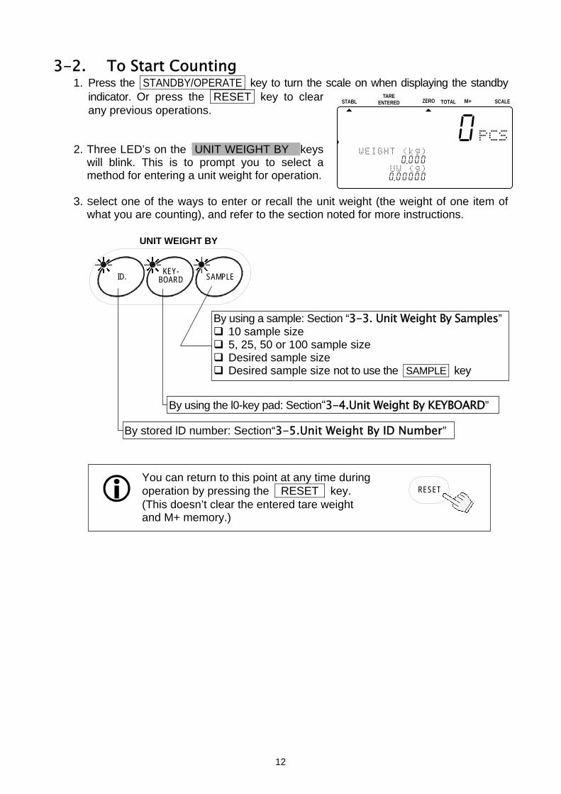
3-2. To Start Counting 1. Press the STANDBY/OPERATE key to turn the scale on when displaying the standby
indicator. Or press the RESET key to clear any previous operations.
2. Three LED’s on the UNIT WEIGHT BY keys will blink. This is to prompt you to select a method for entering a unit weight for operation.
3. Select one of the ways to enter or recall the unit weight (the weight of one item of
what you are counting), and refer to the section noted for more instructions.
STABL
.8888810881pcs
W2WEIGHT (kg) 12134567890 .000 23ASAMPUW (g)
123415670 .0000045678901234567
TARE ENTERED ZERO M+ SCALETOTAL
UNIT WEIGHT BY
KEY- BOARD
You can return to this point at any time during operation by pressing the RESET key. (This doesn’t clear the entered tare weight and M+ memory.)
RESET
SAMPLE ID.
By using a sample: Section “3-3. Unit Weight By Samples” 10 sample size 5, 25, 50 or 100 sample size Desired sample size Desired sample size not to use the SAMPLE key
By using the l0-key pad: Section“3-4.Unit Weight By KEYBOARD”
By stored lD number: Section“3-5.Unit Weight By ID Number”
12
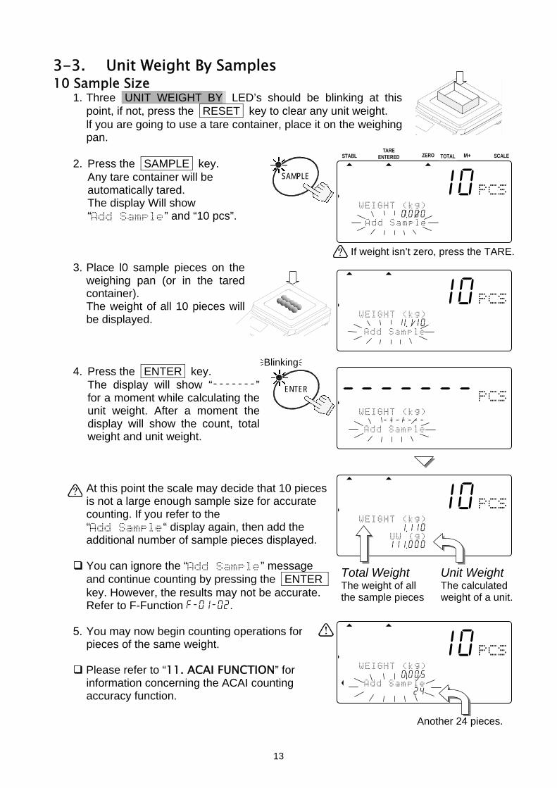
3-3. Unit Weight By Samples 10 Sample Size
1. Three UNIT WEIGHT BY LED’s should be blinking at this point, if not, press the RESET key to clear any unit weight. lf you are going to use a tare container, place it on the weighing pan.
2. Press the SAMPLE key. Any tare container will be
automatically tared. The display Will show “Add Sample” and “10 pcs”.
3. Place l0 sample pieces on the
weighing pan (or in the tared container). The weight of all 10 pieces will be displayed.
4. Press the ENTER key. The display will show “-------”
for a moment while calculating the unit weight. After a moment the display will show the count, total weight and unit weight. At this point the scale may decide that 10 pieces is not a large enough sample size for accurate counting. If you refer to the “Add Sample“ display again, then add the additional number of sample pieces displayed.
You can ignore the “Add Sample” message and continue counting by pressing the ENTER key. However, the results may not be accurate. Refer to F-Function f-01-02.
5. You may now begin counting operations for
pieces of the same weight.
Please refer to “11. ACAI FUNCTION” for information concerning the ACAI counting accuracy function.
Another 24 pieces.
If weight isn’t zero, press the TARE.
.8888810881pcs
W2WEIGHT (kg) 12134567891 .110 23ASAMUUW (g)
12341567111 .000
Total Weight Unit Weight The weight of all The calculated the sample pieces weight of a unit.
SAMPLE
STABL
.8888810881pcs
W2WEIGHT (kg) 12134567890 .000 2A3Add Sample
123456789012345678901234567
TARE ENTERED ZERO M+ SCALETOTAL
.8888810881pcs
W2WEIGHT (kg) 1234567 891 .110
A23Add Sample 123456789012345678901234567
Blinking
.------- 881pcs
W2WEIGHT (kg) 1123456-------
A23Add Sample 123456789012345678901234567
ENTER
.8888810881pcs
W2WEIGHT (kg) 12134567890 .005
A23Add Sample 12134567890124
13
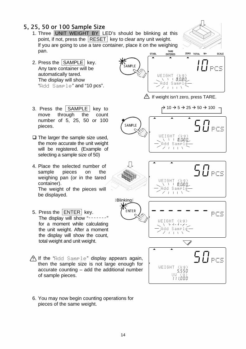
5, 25, 50 or 100 Sample Size 1. Three UNIT WEIGHT BY LED’s should be blinking at this
point, if not, press the RESET key to clear any unit weight. lf you are going to use a tare container, place it on the weighing pan.
2. Press the SAMPLE key. Any tare container will be
automatically tared. The display will show
“Add Sample” and “10 pcs”. 3. Press the SAMPLE key to
move through the count number of 5, 25, 50 or 100 pieces.
The larger the sample size used, the more accurate the unit weight will be registered. (Example of selecting a sample size of 50)
4. Place the selected number of
sample pieces on the weighing pan (or in the tared container). The weight of the pieces will be displayed.
5. Press the ENTER key. The display will show “-------”
for a moment while calculating the unit weight. After a moment the display will show the count, total weight and unit weight. If the “Add Sample” display appears again, then the sample size is not large enough for accurate counting – add the additional number of sample pieces.
6. You may now begin counting operations for
pieces of the same weight.
.8888850881pcs
W2WEIGHT (kg) 11234567895 .550
A23SAMUUW (g) 12341567111 .000
Blinking
SAMPLE
STABL
.8888810881pcs
W2WEIGHT (kg) 12134567890 .000 2A3Add Sample
123456789012345678901234567
ZERO TOTAL M+ TARE
ENTERED SCALE
10 5 25 50 100
SAMPLE
.8888850881pcs
W2WEIGHT (kg) 11234567890 .000
A23Add Sample 123456789012345678901234567
.------- 881pcs
A2WEIGHT (kg) 1213456-------
A23Add Sample 123456789012345678901234567
ENTER
.8888850881pcs
W2WEIGHT (kg) 11234567890 .000
A23Add Sample 123456789012345678901234567
If weight isn’t zero, press TARE.
14

Desired Sample Size 1. Three UNIT WEIGHT BY LED’s should be blinking at this
point, if not, press the RESET key to clear any unit weight. lf you are going to use a tare container, place it on the weighing pan.
2. Press the SAMPLE key.
Any tare container will be automatically tared. The display will show “Add Sample” and “10 pcs”.
3. Use the 0 9 10-key pad to
display the sample size desired.
If you hit the wrong key, press the C key to clear and start again. (Example of selecting a sample size of 20)
4. Place the selected number of
sample pieces on the weighing pan (or in the tared container). The weight of the pieces will be displayed.
5. Press the ENTER key. The display will show “-------”
for a moment while calculating the unit weight.
After a moment the display will show the count, total weight and unit weight. If the “Add Sample” display appears again, then the sample size is not large enough for accurate counting – add the additional number of sample pieces.
.8888820881
6. You may now begin counting operations for
pieces of the same weight.
pcsW2WEIGHT (kg)
12134567892 .220 2A3SAMUUW (g)
12314567111 .000
Blinking
0 9
.8888820881pcs
W2WEIGHT (kg) 11234567890 .000
A23Add Sample 123456789012345678901234567
TUV
DEFABC
MNO
6
1
7 8PQRS
2 3JKLGHI
09WXYZ
4
#
5
C
.
.8888820881pcs
W2WEIGHT (kg) 11234567892 .220
A23Add Sample 123456789012345678901234567
SAMPLE
.8888810881pcs
W2WEIGHT (kg) 11234567890 .000
A23Add Sample 12345678901234567
.------- 881pcs
W2WEIGHT (kg) 1213456-------
A23Add Sample 123456789012345678901234567
ENTER
If weight isn’t zero, press TARE.
15

Desired Sample Size Not Using The SAMPLE Key 1. Three UNIT WEIGHT BY LED’s should be blinking at this
point, if not, press the RESET key to clear any unit weight. lf you are going to use a tare container, place it on the weighing pan and press the TARE key. Be sure the weight display is “0”.
2. Place sample pieces on the
weighing pan (or in the tared container). The weight of the pieces will be displayed.
3. Use the 0 9 10-key pad
to enter the sample size of the pieces you placed.
If you hit the wrong key, press the C key to clear and enter again. (Example of setting a sample size of 20)
4. Press the ENTER key. The display will show dashes for
a moment while calculating the unit weight. After a moment the display will show the count, total weight and unit weight. If the "Add Sample" displays again, then the sample size is not enough for accurate counting - add the additional number of sample pieces.
5. You may now begin counting operations for
pieces of the same weight.
.8888820881pcs
W2WEIGHT (kg) 11234567892 .220 2A3SAMUUW (g)
12345167111 .000
.8888820881pcs
W2WEIGHT (kg) 11234567892 .220
A23Add UW (g) 121345670 .00000
STABL
.8888810881pcs
W2WEIGHT (kg) 12134567890 .000 23ASAMPUW (g)
123415670 .0000045678901234567
TARE ZERO M+ SCALETOTAL ENTERED
Blinking
If weight isn’t zero, press the TARE.
0 9
.8888820881pcs
W2WEIGHT (kg) 11234567890 .000
A23Add Sample 123456789012345678901234567
TUV
DEFABC
MNO
6
1
7 8PQRS
2 3JKLGHI
09WXYZ
4
#
5
C
.
.------- 881pcs
W2WEIGHT (kg) 1213456-------
A23Add Sample 123456789012345678901234567
ENTER
TARE
16
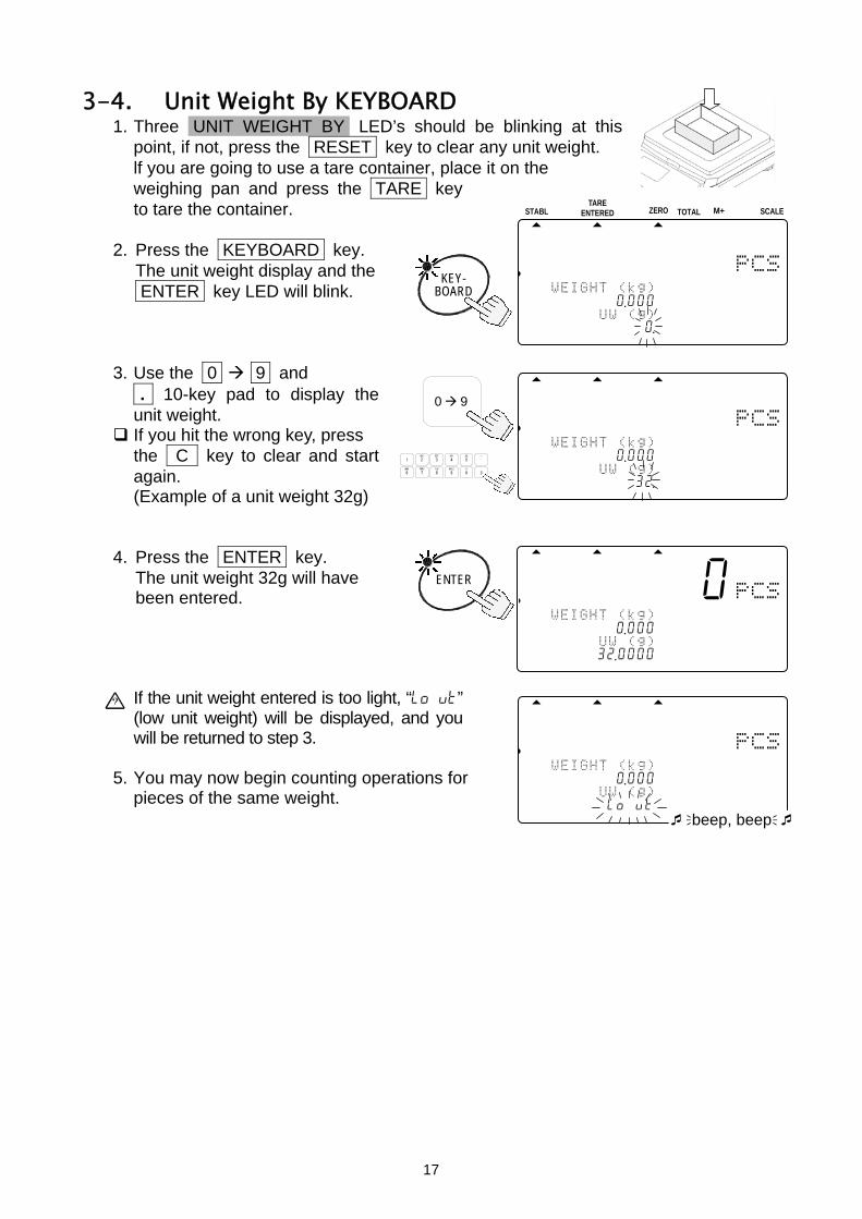
3-4. Unit Weight By KEYBOARD 1. Three UNIT WEIGHT BY LED’s should be blinking at this
point, if not, press the RESET key to clear any unit weight. lf you are going to use a tare container, place it on the weighing pan and press the TARE key to tare the container.
2. Press the KEYBOARD key. The unit weight display and the
ENTER key LED will blink. 3. Use the 0 9 and
. 10-key pad to display the unit weight.
If you hit the wrong key, press the C key to clear and start again. (Example of a unit weight 32g)
4. Press the ENTER key. The unit weight 32g will have
been entered. If the unit weight entered is too light, “lo ut” (low unit weight) will be displayed, and you will be returned to step 3.
5. You may now begin counting operations for
pieces of the same weight.
KEY- BOARD
STABL
.8888810881pcs
W2WEIGHT (kg) 11234567890 .000 2A3SAMUUW (g)
12314567890120 .45678901234567
TARE ZERO M+ SCALETOTAL ENTERED
.------0 881pcs
W2WEIGHT (kg) 1213456---0 .000 23ASAMUUW (g)
1234156732 .0000
ENTER
.------0 881pcs
W2WEIGHT (kg) 123456-0--0 .000 2A3SAMUUW (g)
12314567llo ut beep, beep
0 9
.8888850881pcs
W2WEIGHT (kg) 12134567890 .000 23ASAMUUW (g)
12341567890132 .45678901234567
TUV
DEFABC
MNO
6
1
7 8PQRS
2 3JKLGHI
09WXYZ
4
#
5
C
.
17

3-5. Unit Weight By ID Number 1. If there are no unit weight’s stored in memory, refer to “5-1. Store Unit Weight by
ID Number”. Three UNIT WEIGHT BY LED’s should be blinking at this point, if not, press the RESET key to clear any unit weight.
2. Press the ID key. "id-000000" will be displayed with
000000 blinking.
If you have been using the unit weight by ID number, its ID number stays displayed and blinks.
3. Use the 0 9 10-key pad to
display the ID number.
If you hit the wrong key, press the C key to clear and start again. (Example of ID number "123456")
4. Press the ENTER key. The count display will show "0" and
the scale will recall "12g" previously entered as the unit weight of ID 123456. If there is no unit weight entered for the ID number you tried to recall, “no id” will be displayed, and you will be returned to step 3.
5. You may now begin counting operations for
pieces of the same weight.
.------0 881pcs
W2WEIGHT (kg) 1234561---0 .0004568id-12345623SAAMUUW (g)
1234561712 .0000
ENTER
.------0 881pcs
W2WEIGHT (kg) 1234561---0 .0004568id-no id 23SAMUUW (g)
1234567l0 .0000 beep, beep
ID.
STABLE
.8888810881pcs
W2WEIGHT (kg) 12345167890 .0004578id-00000023SAMUUW (g)
12345670 .00000
TAR SCALEZERO TOTAL M+ ENTERED
0 9
.8888850881pcs
W2WEIGHT (kg) 12134561890 .0004578id-12345623ASAAUUW (g)
123415610 .00000
TUV
DEFABC
MNO
6
1
7 8PQRS
2 3JKLGHI
09WXYZ
4
#
5
C
.
“id-00000” is a special memory area. It always holds the last Unit Weight entered.
When you register a unit weight , it is automatically placed in the ID “id-00000”.
If you clear the unit weight by pressing the RESET key, it can be recalled by recalling the ID “id-00000”.
18

4. ENTERING A TARE WEIGHT
There are two methods of tare operations. Using the TARE key to subtract the displayed container weight directly. Please refer to “3-1. Basic Operations”.
Using the KEYBOARD TARE key to enter a tare weight via the 10-key pad.
4-1. Using the KEYBOARD TARE Key 1. Remove everything from the weighing pan and press the ZERO key to zero the
scale. 2. Press the KEYBOARD TARE key. The weight display will blink
(display is any tare weight previously entered).
3. Use the 0 9 and . 10-key pad
to display the desired TARE weight.
If you hit the wrong key, press the C key to clear and start again. (Example of a tare weight 615g)
4. Press the ENTER key. The weight display changes to
net weight.
The TARE ENTERED indicator will light.
STABL
.8888810881pcs
2AWEIGHT (kg) 121345678-0 .615 23ASAMPUW (g)
123415670 .0000045678901234567
ZERO TOTAL M+TARE
ENTERED SCALE
0 9
STABL
.8888810881pcs
2AWETARE (kg) 12314567890 .000 23SAAMUUW (g)
123451670 .0000045678901234567
TARE ZERO M+ SCALETOTAL ENTERED
.8888850881pcs
2AWETARE (kg) 12314567890 .615 23SAAMUUW (g)
123451670 .00000
TUV
DEFABC
MNO
6
1
7 8PQRS
2 3JKLGHI
09WXYZ
4
#
5
C
.
ENTER
KEY-
TARE BOARD
19

4-2. To Clear TARE Either:
1. Have nothing on the weighing pan. If the ZERO indicator is not displayed, press the ZERO key to zero the scale.
2. Press the TARE key. The weight display will go to “0”,
and the TARE ENTERED indicator will be turned off (tare cleared).
Or: 1. Press the KEYBOARD TARE key. The weight display will blink
(display is any tare weight previously entered).
2. Press the 0 key and press the
ENTER key. 3. The tare weight is cleared and
the TARE ENTERED indicator will be turned off.
STABL
.888-554881pcs
2AAWEIGHT (kg) 1234105678-0 .615 23SAaaMPUW (g)
1234151671 .1100045678901234567
TARE ZERO M+ SCALETOTAL ENTERED
STABL
.888-510881pcs
A2WEIGHT (kg) 12134567890 .000 23SAAMPUW (g)
123456171 .1100045678901234567
TARE ZERO M+ SCALETOTAL ENTERED
TARE
STABL
.8888810881pcs
2AWEIGHT (kg) 123415678-0 .000 23SAAMPUW (g)
123456171 .1100045678901234567
ZERO TOTAL M+TARE
ENTERED SCALE
0
TARE
KEY- BOARD
STABL
.888-554881pcs
2WAETARE (kg) 12341567890 .615 23SAAMUUW (g)
123456171 .1100045678901234567
TARE ZERO M+ SCALETOTAL ENTERED
ENTER
.888-554881pcs
2AWETARE (kg) 12314567890 .000 23SAAMUUW (g)
123451671 .11000
Enter TARE weight ‘0’.
20

5. STORE UNIT WEIGHT
5-1. Store Unit Weight by ID Number The scale can store up to 500 unit weights by 6 digit ID numbers, from 000001 to 999999. To recall, refer to “3-5. Unit Weight By ID Number”.
The scale is initially set to store the ID numbers with a unit weight and an item code only. However, it can be set to store a tare weight, comparator limits and total count by setting F-Function f-01-05.
1. First register a unit weight by any method
– using a sample or via the 10-key pad – and have it displayed.
2. Press the STORE UNIT WEIGHT key.
“id-000000” will appear with 000000 blinking.
If you have been using the unit weight by ID number, its ID number stays displayed and blinks.
3. Use the 0 9 10-key pad to display the new ID number. (Example of ID number “123456”)
If you hit the wrong key, press the C key to clear and start again.
4. Press the ENTER key. The ID number is stored and the display
returns to normal. If the same ID number was previously stored, the scale beeps twice and the ID number display blinks. id-123456 You must then select one of two options: either (a) Overwrite the old ID unit weight, or (b) Select a different ID number:
Press the ENTER key to overwrite the old ID number.
ENTER Press the C key to clear and go to step 3.
C
OR
.888-510881pcs
W2WEIGHT (kg) 12345167891 .110 23SAMAUUW (g)
12345671111 .000
.8888810881pcs
2AWEIGHT (kg) 12304567891 .1104578id-00000023SAMAUUW (g)
12345671111 .000
STORE
WEIGHT UNIT
0 9
.8888810881pcs
WAWEIGHT (kg) 12345671891 .1104678id-12345623SAAMUUW (g)
12314567111 .00045678901234567
TUV
DEFABC
MNO
6
1
7 8PQRS
2 3JKLGHI
09WXYZ
4
#
5
C
.
.-----10 881pcs
WaWEIGHT (kg) 1234516---1 .1104578id-12345623SAaMUUW (g)
12345617111 .000 ENTER
.------0 881pcs
WaWEIGHT (kg) 1231456---1 .1104568id-12345623SAaMUUW (g)
1234561l111 .000 beep, beep
21
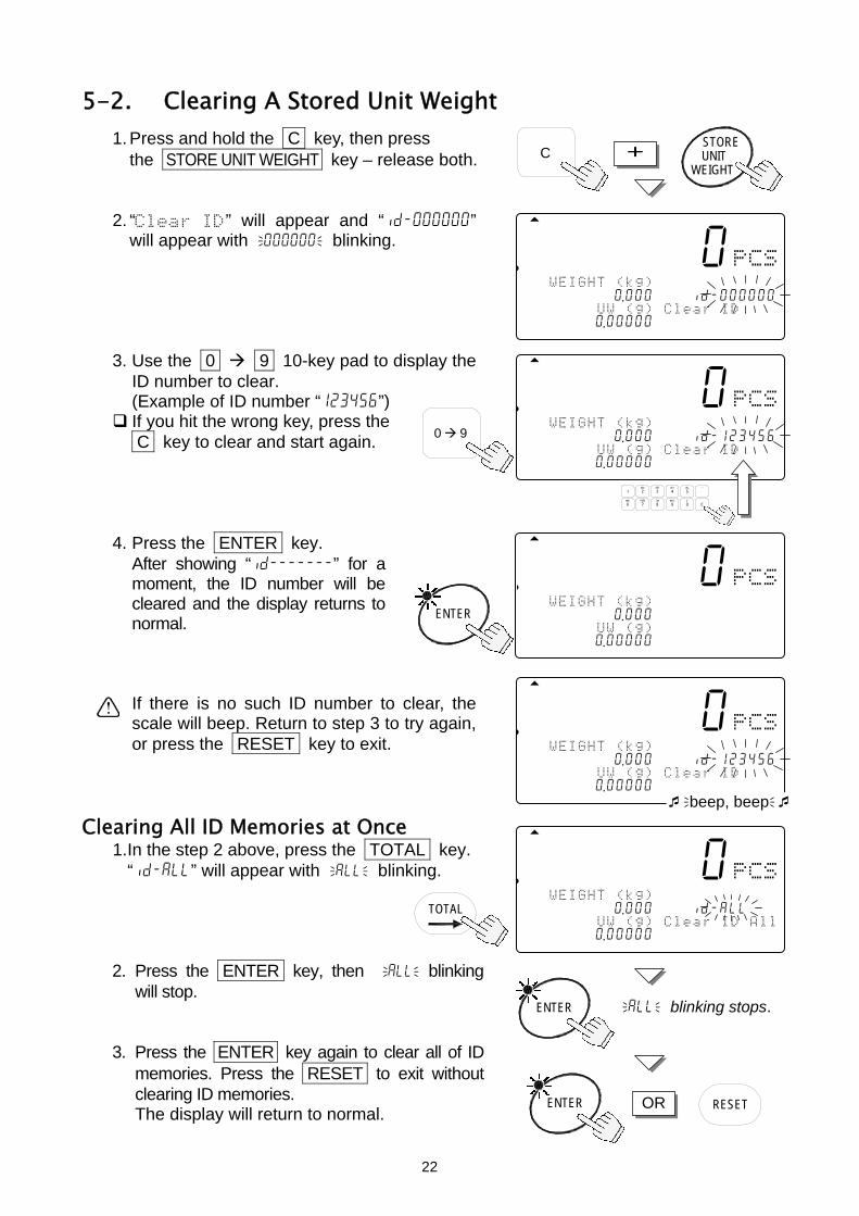
5-2. Clearing A Stored Unit Weight
1. Press and hold the C key, then press the STORE UNIT WEIGHT key – release both.
2. “Clear ID” will appear and “id-000000”
will appear with 000000 blinking. 3. Use the 0 9 10-key pad to display the
ID number to clear. (Example of ID number “123456”)
If you hit the wrong key, press the C key to clear and start again.
4. Press the ENTER key. After showing “id-------” for a
moment, the ID number will be cleared and the display returns to normal.
If there is no such ID number to clear, the
scale will beep. Return to step 3 to try again, or press the RESET key to exit.
STORE
Clearing All ID Memories at Once 1. In the step 2 above, press the TOTAL key. “id-all” will appear with all blinking. 2. Press the ENTER key, then all blinking
will stop. 3. Press the ENTER key again to clear all of ID
memories. Press the RESET to exit without clearing ID memories.
The display will return to normal.
CWEIGHT
UNIT +
881.8888810pcs
2AWEIGHT (kg) 123145678C0 .0004578id-00000023SAMAUUW (g)1Clear ID
123451670 .0000045678901234567
0 9
.8888810881pcs
2AWEIGHT (kg) 123456178C0 .0004578id-12345623SAMAUUW (g)1Clear ID
123451670 .0000045678901234567
TUV
DEFABC
MNO
6
1
7 8PQRS
2 3JKLGHI
09WXYZ
4
#
5
C
.
881.-----10 pcs
2AWEIGHT (kg) 1234516---0 .000 23ASAMUUW (g)
123415670 .00000
ENTER
881.8888810pcs
2AWEIGHT (kg) 123451678-0 .0004578id-12345623SAMUAUW (g)1Clear ID
123451670 .0000045678901234567 beep, beep
.8888810881pcs
2AWEIGHT (kg) 123145678C0 .0005678id-all 23SAMAUUW (g)2Clear ID All
123451670 .00000
TOTAL
ENTER all blinking stops.
ENTER OR RESET
22

5-3. Store Item Code by ID Number
An item code of up to 12 alphanumeric characters can be set using the 10-key pad, and it will be stored with the ID number. 1. Press the STORE UNIT WEIGHT
key. “id-000000” will appear with 000000 blinking.
2. Enter the ID number desired using
the 0 9 10-key pad. 3. Press the STORE UNIT WEIGHT
key again. The symbol “A” with blinking cursor _ will appear.
To return to step 2, press the STORE UNIT WEIGHT key.
To select the symbol “A”, “a” or “1”, press the M+ (A/a) key. Example of entering “A&D Co., Ltd.”: Select the symbol “A” first.
4. Press the 2 (ABC) key to place “A”. “A” A 5. Press the 0 (#) key several times to place “&”. “A” A& 6. Press the 3 (DEF) key to place “D”. “A” A&D 7. Press the TOTAL ( ) key twice to shift the cursor. “A” A&D _ 8. Press the 2 (ABC) key several times to place “C”. “A” A&D C 9. Press the M+ (A/a) key to change the symbol “A” to “a”. “a” A&D C_ 10. Press the 6 (MNO) key several times to place “o”. “a” A&D Co
Repeat these procedures to the last letter. “a” A&D Co.,Ltd.
.8888810881pcs
2AWEIGHT (kg) 12345671891 .1104567id-00000023SAMAUUW (g)
12345617111 .000
STORE
WEIGHT UNIT
STORE
WEIGHT
.8888810881pcs
2AWEIGHT (kg)aA UNIT 12345617891 .1104568id-12345623SAMAUUW (g)A_
12345617111 .00045
Cursor can bemoved using and keys.
0 9
.8888810881pcs
2AWEIGHT (kg) 12345617891 .1104578id-12345623SAMAUUW (g)
12345617111 .000434567
TUV
DEFABC
MNO
6
1
7 8PQRS
2 3JKLGHI
09WXYZ
4
#
5
C
.
This shows which type of character will be entered. A: Capital letter a: Lowercase letter 1: Numeric character
23
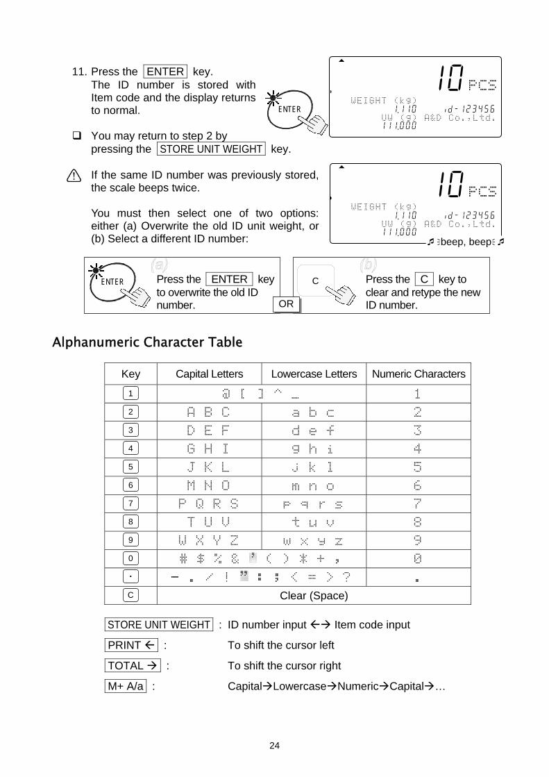
11. Press the ENTER key. The ID number is stored with
Item code and the display returns to normal.
You may return to step 2 by
pressing the STORE UNIT WEIGHT key. If the same ID number was previously stored,
the scale beeps twice. You must then select one of two options:
either (a) Overwrite the old ID unit weight, or (b) Select a different ID number:
Alphanumeric Character Table
Key Capital Letters Lowercase Letters Numeric Characters
@ [ ] ^ _ 1
A B C a b c 2
D E F d e f 3
G H I g h i 4
J K L j k l 5
M N O m n o 6
P Q R S p q r s 7
T U V t u v 8
W X Y Z w x y z 9
# $ % & ( ) * + , 0
- . / ! : ; < = > ? .
Clear (Space)
STORE UNIT WEIGHT : ID number input Item code input
PRINT : To shift the cursor left
TOTAL : To shift the cursor right
M+ A/a : Capital Lowercase Numeric Capital …
.-----10 881pcs
2AWEIGHT (kg) 123516-1--1 .11056 8id-12345623S1AAUUW (g) A&D Co.,Ltd.
12341567111 .000
ENTER
.-----10 881pcs
2AWEIGHT (kg) 123456--1-1 .1105678id-12345623S1AMUUW (g) A&D Co.,Ltd.
1234567l111 .000 beep, beep
Press the ENTER key to overwrite the old ID number.
ENTER Press the C key to clear and retype the new ID number.
C
OR
1
2
3
4
5
6
7
8
9
0
.
C
24

5-4. Unit Weight, Tare, Comparator Limits & Total Count Stored
The scale is initially set to store the ID numbers with a unit weight and an item code only. However, it can be set to store a tare weight, comparator limits and/or total count also by setting F-Function f-01-05. 1. First register a unit weight and a tare weight by
any method. If necessary, set the comparator limits and use the M+ accumulation.
2. Go to step 2 of section “5-1. Store Unit
Weight By ID Numbers”.
When you recall a unit weight by the ID key, the tare, comparator limits and/or total count are also recalled along with the unit weight.
.888-510881pcs
2AWEIGHT (kg) 12345617890 .0004678id-12345623SAMAUUW (g)1ABCDEFGHIJKL
12345617111 .000
“id-00000”, the special memory area, does not store a tare weight, comparator limits and total count along with unit weight.
25

6. USING THE M+ MEMORY
6-1. The M+ Memory Function The scale can accumulate count data by pressing the M+ key, or automatically (refer to the next page). It also keeps track of the number of times you add to the total.
When you view the total by pressing the TOTAL key, you view the number of pieces accumulated and the number of additions (how many times the total was added to). Please refer to “6-2.” and “6-3.” to view or clear the total count.
Adding Using the M+ Key
When stable count data is displayed: 1. Press the M+ key. The M+ indicator will blink for a few seconds.
If the scale beeps 4 times, or the M+ indicator did not blink, then refer to the note below. The M+ indicator will stay ON while there is count in memory.
2. Press the M+ key every time you want to add
to the count. Remember that you may only add the count data once – the scale must return to near zero before it will let you add again.
To Erase the L
1. Press and hthe M+ ke
.888-123881pcs
2AWEIGHT (kg) 12345617813 .6554 23SAAMUUW (g)12
12345617111 .000
STABLE
123M+
M+ A/a
The M+ key is accepted only once for every stable count data.Once accepted, the M+ key is prohibited until the displayreturns to less than +5d (1d = 1 weighing division).
If f-03-02 is set at “1”, then the M+ key can accumulatenegative data. Once the M+ key is accepted, weight data mustreturn within ±5d before the next accumulation.
To store the total count in the ID number, refer to “5-4. UnitWeight, Tare, Comparator Limits & Total Count Stored”.
The total count is not stored in the ID memories automaticallyeven if it was recalled by ID number.
ast M+ Addition old the C key, then press y – release.
C + M+ A/a
26

2. The scale will clear the last M+ addition. If the scale beeps 4 times, there is no M+ addition to erase.
Automatic M+ Accumulation Mode M+ Accumulation can also be done automatically each time you count a different batch, As soon as you have a stable count, it will be added to the M+ memory and the scale will beep . The weight display will have to return to near zero before another count can be added.
Automatic M+ accumulation is set by F-Function f-03-01 at “1”. Only positive counts can be added. If F-Function f-03-02 is set at “1” (to accept negative count data), it will be ignored. Once there is an automatic M+ accumulation, the display must return to less than +5d before another count can be accumulated.
6-2. Viewing the M+ Total 1. Press the TOTAL key. The count display will show the
total count and the TOTAL indicator will come ON.
The number of additions to the M+ memory is also shown.
2. Press the TOTAL key again. The display will return to normal.
TOTAL
TOTAL indicator comes ON.
TOTALCount
Number of additions to M+ memory
STABL
.8888678881pcs
2AWEIGHT (kg) 123456718-0 .000 23SAAMTotal N
12345167111007
ZERO TOTAL M+TARE
ENTERED SCALE
6-3. Clearing the M+ Total 1. Press and hold the C key, then press
the TOTAL key – release both. 2. The scale will clear the M+ memory, and the TOTAL indicator and the M+
indicator will go OFF.
TOTAL C +
The RESET key does not clear the total data.
The total data is held in memory, but if AC/Battery power to scale is interrupted, the total data will be lost.
6-4. The M- Function The scale can subtract count data from M+ memory by using the key. Set the F-Function f-09-01="1" to use the key as M- key.
27
This function is not to clear the last M+ addition, but to subtract count data instead of addition. The number of additions is increased. There is no automatic M- function.
7. COMPARATOR FUNCTION
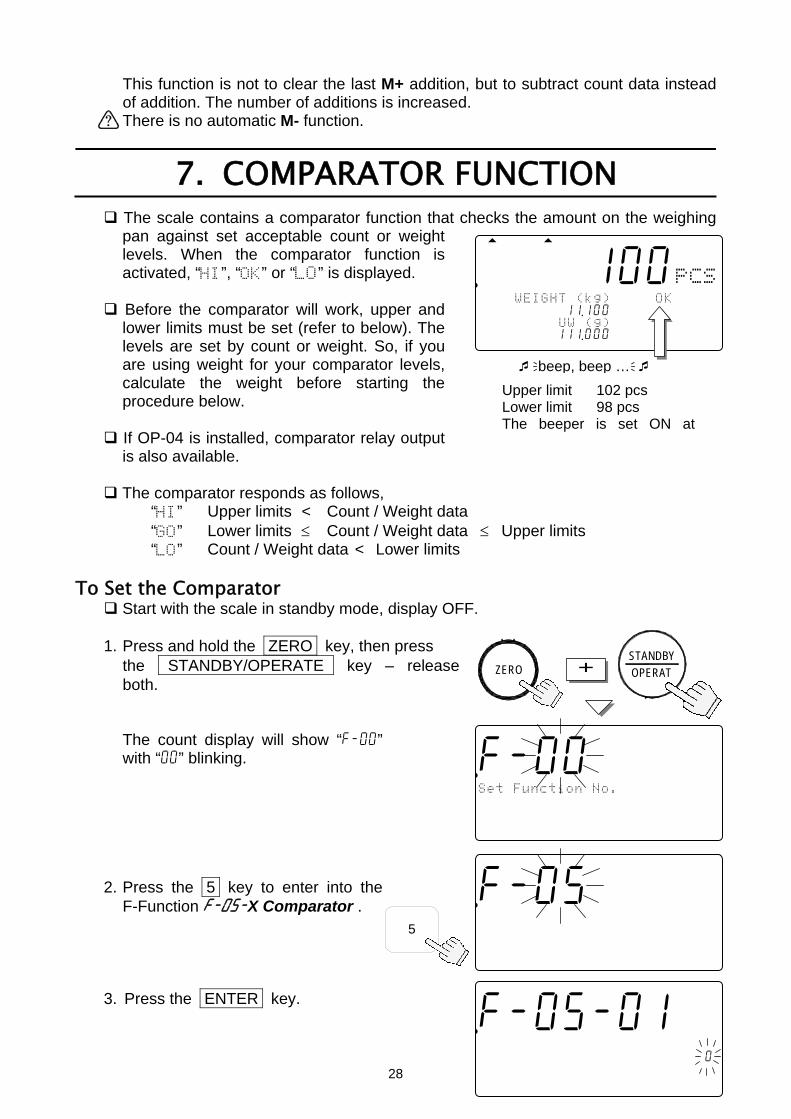
The scale contains a comparator function that checks the amount on the weighing pan against set acceptable count or weight levels. When the comparator function is activated, “HI”, “OK” or “LO” is displayed.
Before the comparator will work, upper and lower limits must be set (refer to below). The levels are set by count or weight. So, if you are using weight for your comparator levels, calculate the weight before starting the procedure below.
If OP-04 is installed, comparator relay output is also available.
The comparator responds as follows,
“HI” Upper limits < Count / Weight data “GO” Lower limits ≤ Count / Weight data ≤ Upper limits “LO” Count / Weight data < Lower limits
.888-100881pcs
2AAWEIGHT (kg)ABDEHOKLOaa 121341567811 .100578id-1234562A3SAAMUUW (g)2BCDEFGHIJKL
123451167111 .000
beep, beep … Upper limit 102 pcs Lower limit 98 pcs The beeper is set ON at
To Set the Comparator Start with the scale in standby mode, display OFF.
1. Press and hold the ZERO key, then press
28
the STANDBY/OPERATE key – release both. The count display will show “f-00” with “00” blinking.
2. Press the 5 key to enter into the
F-Function f-05-X Comparator .
ZERO + OPERATSTANDBY
5
.f-05-01881pcs
Comparator 12345678C000045678id-00000023SAMUUW (g)12Clear ID
12345670 .0000045678901234567
.f-000 881pcs
Set Function No. 12345678C000045678id-00000023SAMUUW (g)12Clear ID
12345670 .0000045678901234567
.f-05-00881pcs
Comparator 12345678C000045678id-00000023SAMUUW (g)12Clear ID
12345670 .0000045678901234567
3. Press the ENTER key.

The count display will show the F-Function and its present setting will blink.
4. Use the 0 6 keys to display the
number of the desired setting.
29
For example, let’s select “1” compare all
data. 5. Press the ENTER key to save the setting
and move to next F-Function, f-05-02. 6. Continue to enter f-05
comparator settings – refer to “10-2. F-Functions” for a listing. If there are no changes to a F-Function, press the ENTER key to move to the next.
7. When finished: press the STANDBY/OPERATE key
to exit. Then, press it to turn the display back ON. Comparator functions will now operate as set.
Viewing Comparator Limits
The comparator limits you are using will be shown by pressing the key. Set f-09-01="0" to use this mode.
1. Press the key, then upper
and lower limits will be shown. 2. Press the key twice, the
display will return to normal.
Changing Comparator Limits Temporarily Set f-09-01="0" to use this mode.
1. In step 1 above, press the ENTER key, the
upper limit value will blink. 2. Change the upper limit using
the 10-key pad and press the ENTER key. The upper limit will stop blinking and the lower limit blinks.
3. Change the lower limit using the 10-key pad and
press the ENTER key. Then the display will return to normal with the new limits.
.f-05-01881pcs
Comparator 12345678C000045678id-00000123SAMUUW (g)12Clear ID
12345670 .0000045678901234567
TUV
DEFABC
MNO
6
1
7 8PQRS
2 3JKLGHI
09WXYZ
4
#
5
C
.
ENTER
.f-05-02881pcs
Comparator 12345678C000045678id-00000023SAMUUW (g)12Clear ID
12345670 .0000045678901234567
ENTER To ENTER
or MOVE to next
.888-100881pcs
2AAWEIGHT (kg)ABDEHi Limit121341567811 .100578id-1231022A3SAAMUUW (g)2BCDLo Limit
123451167111 .000123456789098
.888-100881pcs
2AAWEIGHT (kg)ABDEHi Limit121341567811 .100578id-1231052A3SAAMUUW (g)2BCDLo Limit
123451167111 .000123456789098
ENTER
.888-100881pcs
2AAWEIGHT (kg)ABDEHi Limit121341567811 .100578id-1231022A3SAAMUUW (g)2BCDLo Limit
123451167111 .000123456789098
Upper limit Lower limit

These temporary limits will disappear when the display is turned off.
8. TIME AND DATE FUNCTION
The scale has a time and date function and that data can be sent through the RS-232C interface. There are two ways to set time and date.
To Set in the F-Function Settings
Start with the scale in standby mode, with the display is turned off. 1. Press and hold the ZERO key, then press the STANDBY/OPERATE key
– release both to enter the F-Function setting mode. The count display will show “f-00” with “00” blinking. 2. Key in 1 1 and press the ENTER key
30
to display the setting value, time and date. If you want to change the order of year,
month and date, use the 0 2 to change the setting.
3. Press the C . The first digit of time
and date will blink. Use the 10-key pad to set the time
and date. The "seconds" value” is fixed to “00”.
4. Press the ENTER key to return to the step 2
and the clock will start from “00” seconds. 5. Press the STANDBY/OPERATE key to exit,
and press it again to turn the display back ON. Using the Key to Set the Time and Date
Set the F-Function f-09-01="0" to use the key as this function. 1. Press the key twice to
display the time and date. 2. Press the ENTER key, then
the first digit of date will blink. 3. Use the 10-key pad to set the date and press the
ENTER key. Then the first digit of time will blink. The “seconds” value is fixed to “00”.
.f-11-01881pcs
Comparator 12345678901234567890123456123SAMUUWMAADAAAAYAAhAAmAAs
12345670 .0201202003012034056
C
.f-11-01881pcs
Comparator 12345678901234567890123456123SAMUUWMAADAAAAYAAhAAmAAs
12345670 .0201202003012034000
The second display is fixed to
TUV
DEFABC
MNO
6
1
7 8PQRS
2 3JKLGHI
09WXYZ
4
#
5
C
.
.888-100881pcs
2AAWEIGHT (kg)ABDE Y M D121341567811 .100572003 2 122A3SAAMUUW (g)2BCD h m s
123451167111 .000123412 34 56
.888-100881pcs
2AAWEIGHT (kg)ABDE Y M D121341567811 .100572003 2 122A3SAAMUUW (g)2BCD h m s
123451167111 .000123412 34 00
ENTER
Twice
TUV
DEFABC
MNO
6
1
7 8PQRS
2 3JKLGHI
09WXYZ
4
#
5
C
.
ENTER
4. Use the 10-key pad to set the time and press the ENTER key to return to normal. The clock will start from “00” seconds.
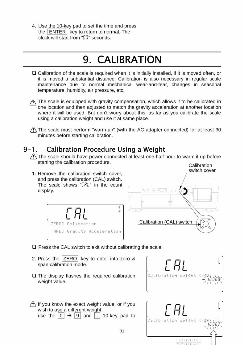
9. CALIBRATION
Calibration of the scale is required when it is initially installed, if it is moved often, or it is moved a substantial distance. Calibration is also necessary in regular scale maintenance due to normal mechanical wear-and-tear, changes in seasonal temperature, humidity, air pressure, etc.
The scale is equipped with gravity compensation, which allows it to be calibrated in one location and then adjusted to match the gravity acceleration at another location where it will be used. But don’t worry about this, as far as you calibrate the scale using a calibration weight and use it at same place.
The scale must perform "warm up" (with the AC adapter connected) for at least 30 minutes before starting calibration.
9-1. Calibration Procedure Using a Weight The scale should have power connected at least one-half hour to warm it up before starting the calibration procedure.
1. Remove the calibration switch cover, and press the calibration (CAL) switch.
The scale shows “Cal” in the count display.
Press the CAL switch to exit without calibrating the scale. 2. Press the ZERO key to enter into zero &
span calibration mode.
The display flashes the required calibration weight value. If you know the exact weight value, or if you wish to use a different weight, use the 0 9 and . 10-key pad to
.88Cal10881pcs
[ZERO] Calibration 1234567890123 [TARE] Gravity Acceleration1234567890123
Calibrationswitch cover
Calibration (CAL) switch
.88Cal10881pcs
Calibration weight (kg) Cal4567890123aaaaaaaaa10 .000[TARE] Gravity Acceleration
.88Cal10881pcs
Calibration weight (kg) Cal4567890123aaaaaaaaa10 .002[TARE] Gravity Acceleration1234567890123
TUV
DEFABC
MNO
6
1
7 8PQRS
2 3JKLGHI
09WXYZ
4
#
5
C
.
31
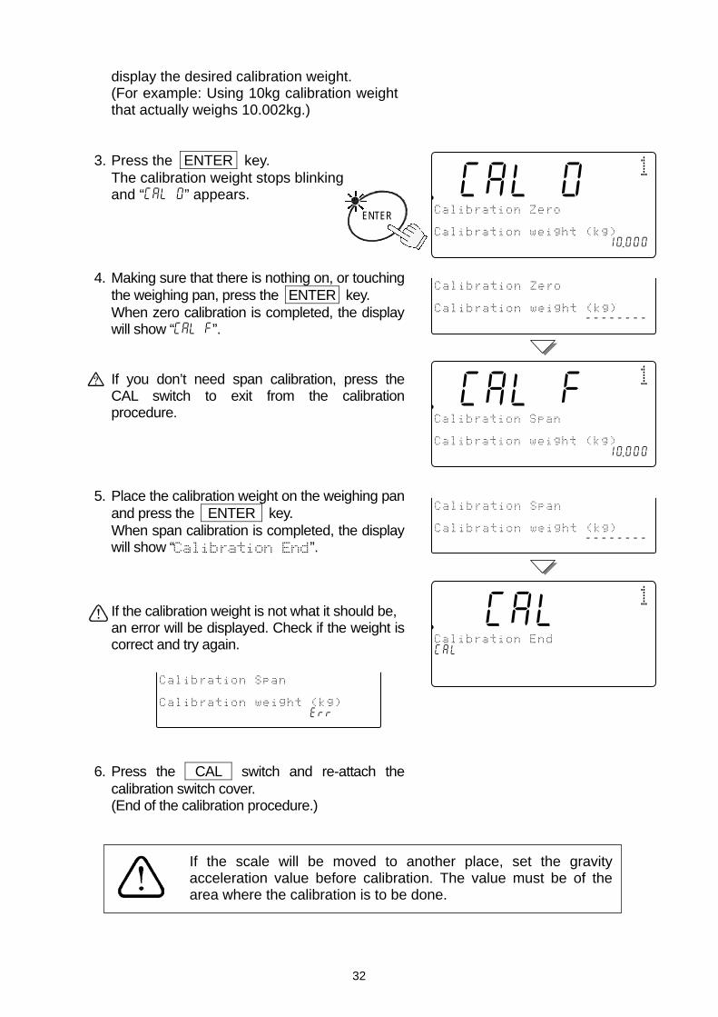
display the desired calibration weight. (For example: Using 10kg calibration weight that actually weighs 10.002kg.)
3. Press the ENTER key.
The calibration weight stops blinking and “Cal 0” appears.
4. Making sure that there is nothing on, or touching
the weighing pan, press the ENTER key. When zero calibration is completed, the display will show “Cal f”.
If you don’t need span calibration, press the CAL switch to exit from the calibration procedure.
5. Place the calibration weight on the weighing pan
and press the ENTER key. When span calibration is completed, the display will show “Calibration End”. If the calibration weight is not what it should be, an error will be displayed. Check if the weight is correct and try again.
6. Press the CAL switch and re-attach the
calibration switch cover. (End of the calibration procedure.)
ENTER
.8Call00881pcs
Calibration Zero Cala0 Calibration weight (kg) 123456789012345678901210 .000
.8Callf0881pcs
Calibration Span Calaf Calibration weight (kg) 123456789012345678901210 .000
Calibration Zero Cala0 Calibration weight (kg) 1234567890123456789--------
Calibration Span Calaf Calibration weight (kg) 1234567890123456789--------
.88Cal10881pcs
Calibration End Cala Calibration weight (kg) 123456789012345678901210 .000
Calibration Span Calaf Calibration weight (kg) 1234567890123456789err
If the scale will be moved to another place, set the gravity acceleration value before calibration. The value must be of the area where the calibration is to be done.
32

9-2. Gravity Compensation
When the scale is first used or has been moved to different place, it should be calibrated using a calibration weight. But if the calibration weight cannot be prepared, the gravity acceleration correction will compensate the scale. Change the gravity acceleration value of the scale to the value of the area where it will be used. Refer to the gravity acceleration map appended to the end of this manual.
1. In step 1 of the previous procedure, press the TARE key.
The display flashes the gravity acceleration value stored in the scale.
2. Use the 0 9 and . 10-key pad to
display the desired gravity acceleration value. (Example of the value 9.800 m/s2.) 3. Press the ENTER key.
The scale will store the new value. If necessary to calibrate the scale using a weight, go to step 2 of the previous section.
4. Press the CAL switch and re-attach the calibration switch cover. (End of the calibration procedure.)
.88Cal10881pcs
Gravity Acceleration Cal45678g0123aaaaaaaaaa9 .798Memory Gravity Acceleration1234567890123
ENTER
.88Cal10881pcs
Gravity Acceleration Cal45678g0123aaaaaaaaa19 .800[TARE] Gravity Acceleration1234567890123
TUV
DEFABC
MNO
6
1
7 8PQRS
2 3JKLGHI
09WXYZ
4
#
5
C
.
.88Cal10881pcs
[ZERO] Calibration 1234567890123 [TARE] Gravity Acceleration1234567890123
33

10. F-FUNCTION PARAMETERS
10-1. To Change or View F-Function Settings Start with the scale in standby mode, with the display is turned off.
1. Press and hold the ZERO key, then press
the STANDBY/OPERATE key. The count display will show “f-00” with “00” blinking. Then release the both keys.
2. Press the 0 9 keys to display the
number of the F-Function.
For example: the 5 key to enter into the F-Function f-05-X Comparator. 3. Press the ENTER key.
The count display will show the F-Function and its present setting will blink.
4. You may now either change the setting (step 5)
or move to the next F-Function (step 6). 5. Use the 0 9 keys to change the setting.
The C key clears the input setting if you press the wrong key and want to re-enter.
If you make a mistake and want to escape without saving any changes made after the last time the ENTER key was pressed – press the STANDBY/OPERATE key to exit.
After the ENTER key is pressed, the data is entered.
.f-05-00881pcs
Comparator 12345678C000045678id-00000023SAMUUW (g)12Clear ID
12345670 .0000045678901234567
TUV
DEFABC
MNO
6
1
7 8PQRS
2 3JKLGHI
09WXYZ
4
#
5
C
.
ZERO + OPERATSTANDBY
.f-05-01881pcs
Comparator 12345678C000045678id-00000023SAMUUW (g)12Clear ID
12345670 .0000045678901234567
.f-05-01881pcs
Comparator 12345678C000045678id-00000123SAMUUW (g)12Clear ID
12345670 .0000045678901234567
TUV
DEFABC
MNO
6
1
7 8PQRS
2 3JKLGHI
09WXYZ
4
#
5
C
.
.f-000 881pcs
Set Funtion No. 12345678C000045678id-00000023SAMUUW (g)12Clear ID
12345670 .0000045678901234567
34

6. Press the ENTER key to save any changes and/or move to the next item.
7. When finished: Press the STANDBY/OPERATE
key to exit. Then, press it to turn the display back on. The new settings will operate as set.
ENTER
.f-05-02881pcs
Comparator 12345678C000045678id-00000023SAMUUW (g)12Clear ID
12345670 .0000045678901234567
OPERATSTANDBY
35

10-2. F-Functions “ ” designates factory settings.
F-00-X Weighing Unit
Weight Display.
0 kg (kilograms, FC-i series), g (grams,
13 lb (pounds).
Unit Weight (when “lb” is selected).
0 lb as piece weight.
13 lb as 1,000 piece weight. F-01-X Operations
Operation Mode.
03 Normal operation. All features and key
1 Simplified operation. The unit weigsample only. All other keys are disable
“Add” Sample Request Override.
If the sample weight is too light and thmore sample pieces, using this F-Funcan be entered without adding the reqOr disable the “Add” sample request fu
0 “Add” sample request function is disacan be accepted without “Add” more s
13 The unit weight can be entered witsample pieces (via the ENTER key)
2 The unit weight cannot be entered wsample pieces (via the ENTER key)
Auto REMOTE SCALE After Unit WeigThe scale can be set to the remote scaregistration, instead of having to manua REMOTE SCALE key. Please note tany other use of the REMOTE SCALE
03 No automatic switching.
1 Automatic switching to the remote sca
2 Automatic switching to the main scale.
f-01-01
f-01-02
f-01-03
F-01-03 requires OP-05 and a remote scale
f-00-01
f-00-02
36
USA Version ONLY
FC-Si series)
s available. ht registration is by d.
e scale asks to “Add”ction, the unit weight
uested sample pieces. nction. bled. Light unit weight ample request. hout requested “Add”. ithout requested “Add”. ht Registration. le after the unit weight lly press the
hat this does not affect key.
le.
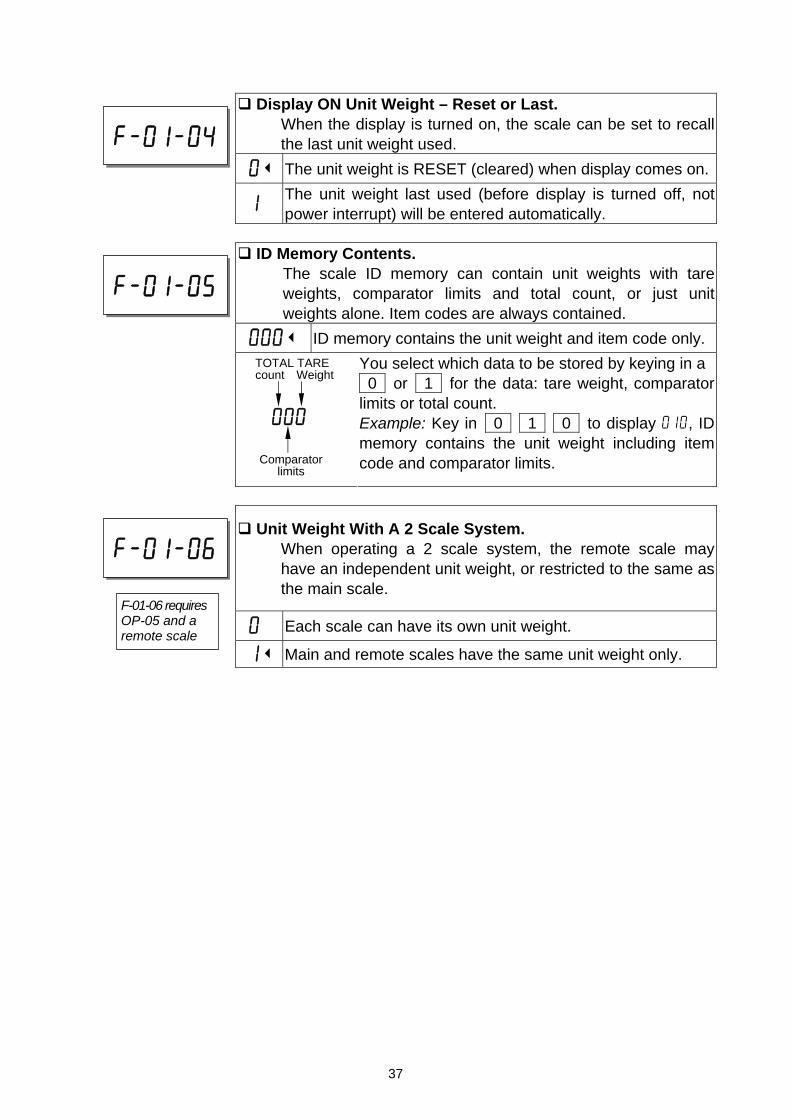
Display ON Unit Weight – Reset or Last.
When the display is turned on, the scale can be set to recall the last unit weight used.
03 The unit weight is RESET (cleared) when display comes on.
1 The unit weight last used (before display is turned off, not power interrupt) will be entered automatically.
ID Memory Contents.
The scale ID memory can contain unit weights with tare weights, comparator limits and total count, or just unit weights alone. Item codes are always contained.
0003 ID memory contains the unit weight and item code only.
You select which data to be stored by keying in a 0 or 1 for the data: tare weight, comparator limits or total count. Example: Key in 0 1 0 to display 010, ID memory contains the unit weight including item code and comparator limits.
Unit Weight With A 2 Scale System. When operating a 2 scale system, the remote scale may have an independent unit weight, or restricted to the same as the main scale.
0 Each scale can have its own unit weight.
13 Main and remote scales have the same unit weight only.
f-01-04
f-01-06
F-01-06 requires OP-05 and a remote scale
f-01-05
000
Comparator limits
TOTAL TARE count Weight
37
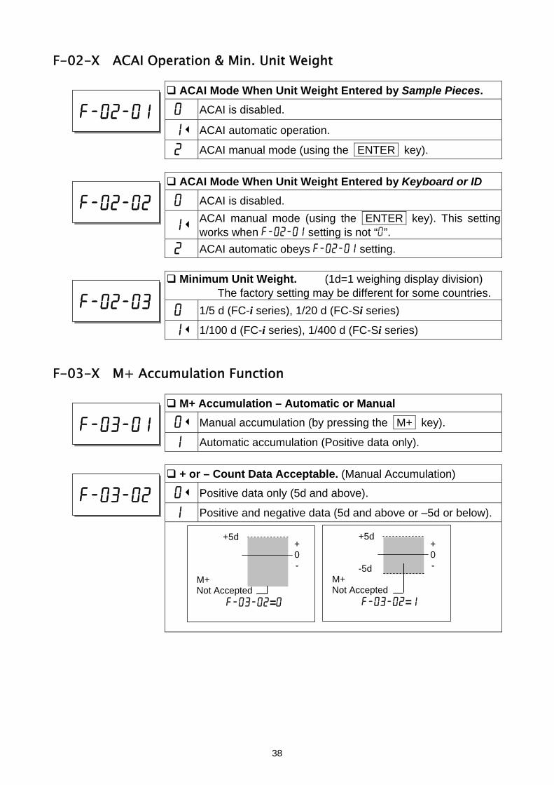
F-02-X ACAI Operation & Min. Unit Weight
ACAI Mode When Unit Weight Entered by Sample Pieces.
0 ACAI is disabled.
13 ACAI automatic operation.
2 ACAI manual mode (using the ENTER key).
ACAI Mode When Unit Weight Entered by Keyboard or ID
0 ACAI is disabled.
13 ACAI manual mode (using the ENTER key). This setting works when f-02-01 setting is not “0”.
2 ACAI automatic obeys f-02-01 setting.
Minimum Unit Weight. (1d=1 weighing display division) The factory setting may be different for some countries.
0 1/5 d (FC-i series), 1/20 d (FC-Si series)
13 1/100 d (FC-i series), 1/400 d (FC-Si series)
F-03-X M+ Accumulation Function
M+ Accumulation – Automatic or Manual
03 Manual accumulation (by pressing the M+ key).
1 Automatic accumulation (Positive data only).
+ or – Count Data Acceptable. (Manual Accumulation)
03 Positive data only (5d and above).
1 Positive and negative data (5d and above or –5d or below).
f-02-01
f-02-02
f-02-03
f-03-01
f-03-02
+5d M+ Not Accepted
f-03-02=0
+0-
+5d
-5d M+ Not Accepted
f-03-02=1
+ 0 -
38
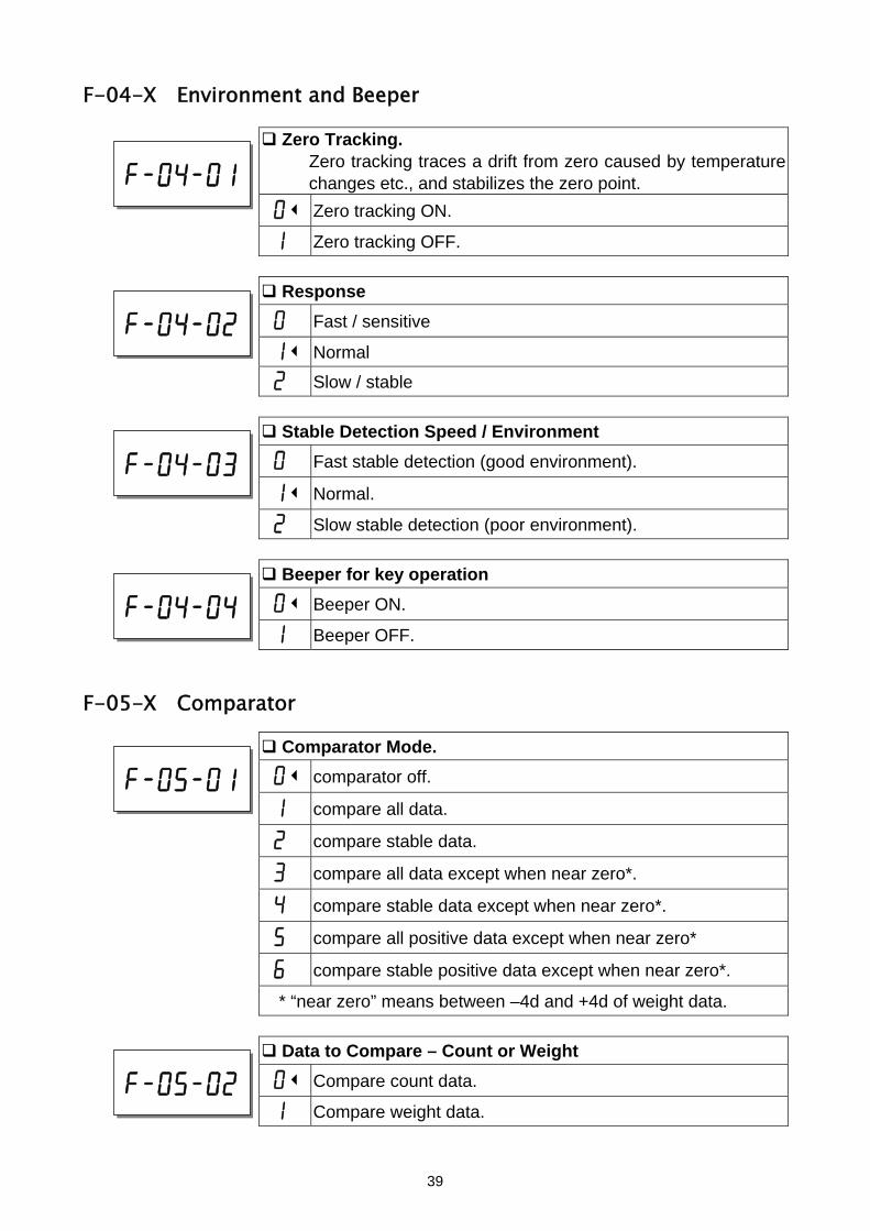
F-04-X Environment and Beeper
Zero Tracking. Zero tracking traces a drift from zero caused by temperature changes etc., and stabilizes the zero point.
03 Zero tracking ON.
1 Zero tracking OFF.
Response
0 Fast / sensitive
13 Normal
2 Slow / stable
Stable Detection Speed / Environment
0 Fast stable detection (good environment).
13 Normal.
2 Slow stable detection (poor environment).
Beeper for key operation
03 Beeper ON.
1 Beeper OFF.
F-05-X Comparator
Comparator Mode.
03 comparator off.
1 compare all data.
2 compare stable data.
3 compare all data except when near zero*.
4 compare stable data except when near zero*.
5 compare all positive data except when near zero*
6 compare stable positive data except when near zero*.
* “near zero” means between –4d and +4d of weight data.
Data to Compare – Count or Weight
03 Compare count data.
1 Compare weight data.
f-04-01
f-04-02
f-04-03
f-04-04
f-05-01
f-05-02
39
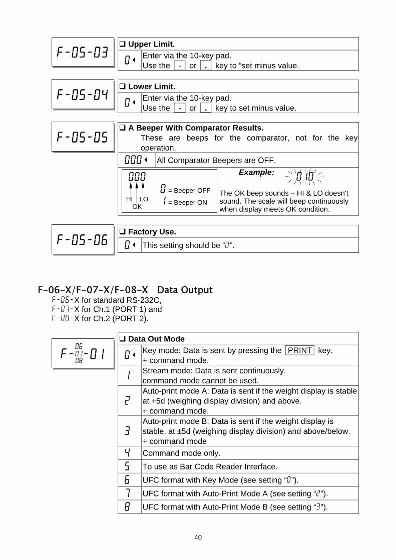
Upper Limit.
03 Enter via the 10-key pad. Use the - or . key to “set minus value.
010
Lower Limit.
03 Enter via the 10-key pad. Use the - or . key to set minus value.
f-05-03
f-05-04
A Beeper With Comparator Results.
These are beeps for the comparator, not for the key operation.
0003 All Comparator Beepers are OFF.
Example: The OK beep sounds – HI & LO doesn't sound. The scale will beep continuously when display meets OK condition.
f-05-05
000 0 = Beeper OFF
1 = Beeper ON HI LO OK
Factory Use.
03 This setting should be “0”.
f-05-06
F-06-X/F-07-X/F-08-X Data Output f-06-X for standard RS-232C, f-07-X for Ch.1 (PORT 1) and f-08-X for Ch.2 (PORT 2).
Data Out Mode
03 Key mode: Data is sent by pressing the PRINT key. + command mode.
1 Stream mode: Data is sent continuously. command mode cannot be used.
2 Auto-print mode A: Data is sent if the weight display is stable at +5d (weighing display division) and above. + command mode.
3 Auto-print mode B: Data is sent if the weight display is stable, at ±5d (weighing display division) and above/below. + command mode
4 Command mode only.
5 To use as Bar Code Reader Interface.
6 UFC format with Key Mode (see setting “0”).
7 UFC format with Auto-Print Mode A (see setting “2”).
8 UFC format with Auto-Print Mode B (see setting “3”).
f-X-01 0607 08
40

Data to be Sent.
001003 Count data sent.
You select which data to be sent by keying in a 0 or 1 for the data: Date, ID no., PCS (count), weight or unit weight. Example: Key in 0 1 1 0 0 to display 01100, this setting would send only the ID number and the count.
f-X-02 0607 08
00000
WeightPCS(count)
Date/Time Unit ID Weight
Data Format
03 Format for AD-8121 MODE 1.
1 Format for AD-8121 MODE 3.
No difference between “0” and ”1” when used with the UFC format.
2 Format for general apparatuses, computers, etc.
f-X-03 0607 08
Baud Rate
03 2400 bps.
1 4800 bps.
2 9600 bps.
f-X-04 0607 08
Data Length and Parity
03 7 bits, even parity.
1 7 bits, odd parity.
2 8 bits, non parity.
f-X-05 0607 08
41
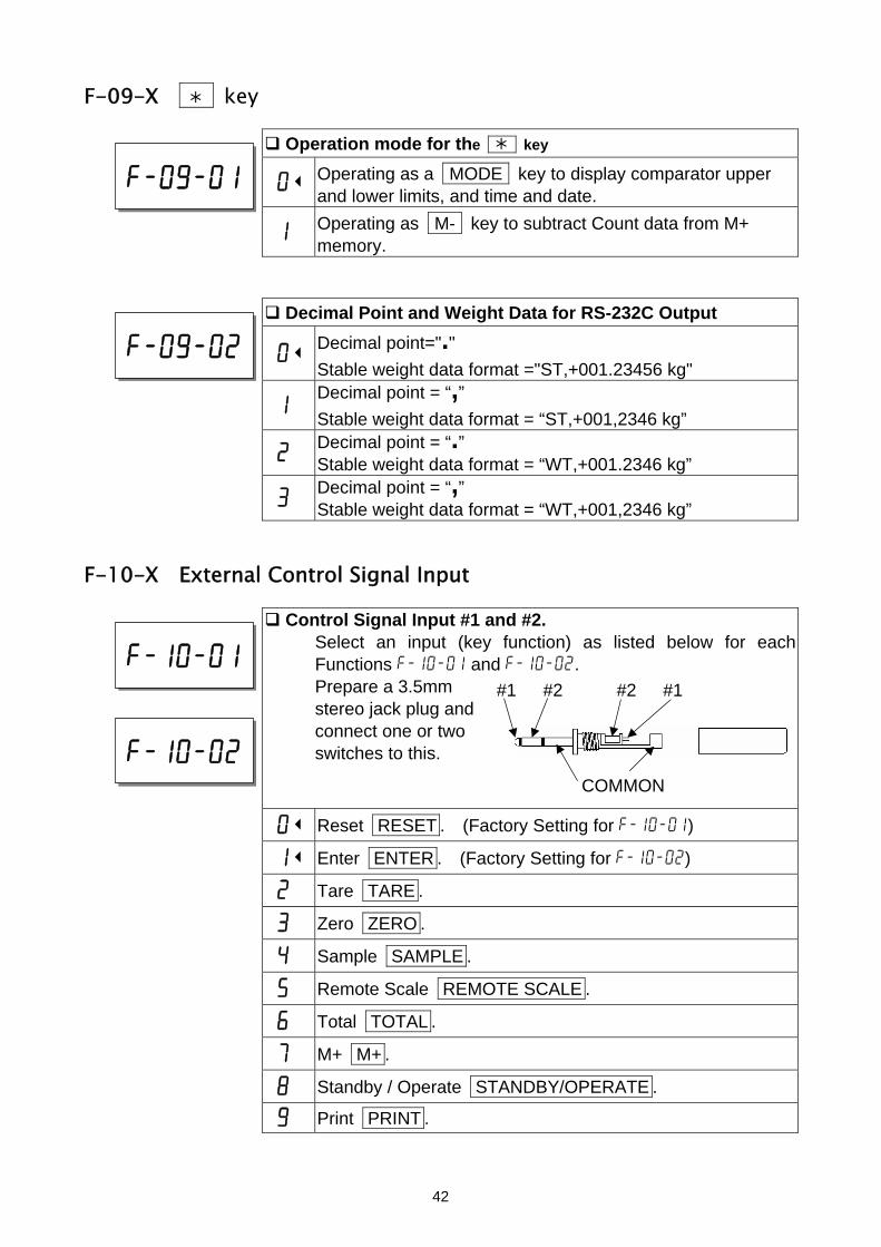
F-09-X key
Operation mode for the key
03 Operating as a MODE key to display comparator upper and lower limits, and time and date.
1 Operating as M- key to subtract Count data from M+ memory.
Decimal Point and Weight Data for RS-232C Output
03 Decimal point="." Stable weight data format ="ST,+001.23456 kg"
1 Decimal point = “,” Stable weight data format = “ST,+001,2346 kg”
2 Decimal point = “.” Stable weight data format = “WT,+001.2346 kg”
3 Decimal point = “,” Stable weight data format = “WT,+001,2346 kg”
F-10-X External Control Signal Input
Control Signal Input #1 and #2. Select an input (key function) as listed below for each Functions f-10-01 and f-10-02. Prepare a 3.5mm stereo jack plug and connect one or two switches to this.
03 Reset RESET . (Factory Setting for f-10-01)
13 Enter ENTER . (Factory Setting for f-10-02)
2 Tare TARE .
3 Zero ZERO .
4 Sample SAMPLE .
5 Remote Scale REMOTE SCALE .
6 Total TOTAL .
7 M+ M+ .
8 Standby / Operate STANDBY/OPERATE .
9 Print PRINT .
f-10-01
f-10-02
f-09-01
f-09-02
#1 #2
COMMON
#2 #1
42

F-11-X Time & Date
Time and Date Display. Select the order of date display.
0 Year-Month-Date.
13 Month-Date-Year.
2 Date-Month-Year.
f-11-01
43

11. ACAI FUNCTION
11-1.
11-2.
ACAI Automatic Counting Accuracy Improvement
The ACAITM (Automatic Counting Accuracy Improvement) function recalculates the unit weight as more pieces are added to improve count accuracy. When the scale calculates the unit weight from sample pieces, the more sample pieces that are used, the higher the accuracy.
STABL
.8888828881pcs
AAWEIGHT (kg) 12134567893 .108 234A56UUW (g)
12314567111 .000
ZERO TOTAL M+ TARE
ENTERED SCALE
ACAI
SAMPLE TOO LIGHT
ACAI Notes You must do the ACAI procedure just after you set the unit weight. The samples must be still on the weighing pan.
Do not take the samples off until the end of the ACAI procedure.
You don’t have to count out the pieces when you add, just stay within the ACAI range.
Continue the ACAI procedure to reach the largest amount that you will be counting.
If you want the most precise counting results for every different batch of the same items, use ACAI every time you start counting the next batch.
The ACAI does not work when you use a remote scale if the unit weight was set on the main scale and vice versa.
The ACAI function is initially set to manual operation when the unit weight is set digitally by the keyboard, by ID memory or using computer via the serial interface. This can be set to the automatic mode. The ACAI mode when the unit weight is entered by ID or digital input is controlled by F-Function f-02-02. It is initially set at “0”, ACAI manual operation mode. Set to “1” for automatic operation mode.
.8888810881pcs
A2WEIGHT (kg) 12134567891 .110 23ASAMUUW (g)
12341567111 .000
.8888821881pcs
A2WEIGHT (kg) 12134567892 .331 23ASAMUUW (g)
12341567111 .000
ACAI
ACAI Automatic Operation
1. To start ACAI automatic operation, the unit weight must be registered and the samples still on the weighing pan.
2. Add pieces within the nearest
ACAI range (refer to table below). A good rule of thumb is to roughly double the amount on the weighing pan.
44

Pcs On the ACAI Weighing Pan Addition Range 60 63~123
10 13~27 70 73~139 20 23~50 80 83~153 30 33~71 90 93~167 40 43~90 100 103~300 50 53~107 over 200 203~493
STABLE
ACAI
STABLE
ACAI
STABLE
ACAI
As you add, the ACAI indicator will be ON
as long as you are in range.
When you stop adding and the display
becomes STABLE, the ACAI indicator will blink.
After the new unit weight is calculated,
the indicator will disappear,
3. Continue adding pieces within the ACAI range until you have reached a sample size
as large as the largest number of pieces that you will be counting.
When you have added the maximum number of pieces required, remove the sample pieces and start your counting job.
11-3. ACAI Manual Operation
The ACAI procedure can also be controlled manually. The ACAI will not recalculate the unit weight until the ENTER key is pressed (as long as it is at the proper time and the guidelines in the ACAI notes have been followed).
The ACAI manual mode is controlled by F-Function f-02-01, set at “2”.
To start ACAI manual operation, the unit weight must be registered and the samples still on the weighing pan.
1. Add pieces within the nearest ACAI range
(refer to table in the previous section). The ACAI indicator will stay ON as long as you are within the ACAI range.
2. Wait until the display becomes stable and press the ENTER key.
When the new unit weight is calculated, the indicator will blink for a moment and disappear.
3. Continue adding pieces within the ACAI range until you have reached a sample size
as large as the largest number of pieces that you will be counting.
When you have added the maximum number of pieces required, remove the sample pieces and start your counting job.
.8888821881pcs
A2WEIGHT (kg) 12134567892 .331 23ASAMUUW (g)
12341567111 .000
ACAI
45

12. RS-232C SERIAL INTERFACE
The scale has not only a standard RS-232C interface but also optional interfaces, Ch.1 and Ch.2.
The specifications described in this section are common to all of the RS-232C interfaces.
12-1. RS-232C Specifications
Transmission system EIA RS-232C Transmission form Asynchronous, bi-directional, half-duplex Data format Baud rate: 2400, 4800, 9600 bps Data: 7 bits + parity 1bit (even or odd)
or 8 bits (non-parity) Start bit: 1 bit Stop bit: 1 bit Code: ASCII Terminator: Data Send / CRLF (CR: 0Dh, LF: 0Ah) Data Receive / CR or CRLF
LSB0
1
2
3
4
5
MSB6
1 (-15V~-5V) 0 (5V~15V)
Stop bit Parity bit Data bit Start bit
Pin connections D-sub 9pin male connector
1 N.C. 2 Transmit data 3 Receive data 4 N.C. 5 Signal ground 6 Data set ready 7 Request to send 8 Clear to send 9 N.C. Inside of the Scale
The scales are designated as DCE (Data Communication Equipment).
46

12-2. Data Output Mode
The data output modes and parameters are set by F-Functions in f-06 / 07 / 08-X as described in the F-Function parameters, section 9.
To control the scale using commands from an external device, refer to “12-5. Command Mode”.
Refer to “12-5. Command Mode” about the output data format.
Data Out Mode (f-06/07/08-01)
Key Mode (f-06/07/08-01="0") When the weight display is stable, data is sent by pressing the PRINT key. The count display will blink when the data has been sent.
Stream Mode (f-06/07/08-01="1") Data is sent continuously. The data-update rate is approximately 5 times per second for f-06/07/08-03="2". For f-06/07/08-3="0" or "1", the interval between continuous data is approximately 2 seconds.
Auto-print Mode A (f-06/07/08-01="2") Data is sent if the WEIGHT display is stable at +5d (weighing display division) and above. The next transmission can not occur until after the weight display falls below +5d.
Auto-print Mode B (f-06/07/08-01="3") Data is sent if the WEIGHT display is stable at ±5d (weighing display division) and above/below. The next transmission can not occur until after the weight display falls between –5d and +5d.
To use with the UFC format. Refer to "12-7. Using UFC (Universal Flex Coms) Function"
Data to be Sent (f-06/07/08-02)
Select which data is o be sent by keying in a 0 or 1 for the data: Date / time, ID Number, PCS (count), weight or unit weight. Example: Key in 0 1 1 0 0 to display 01100, this setting would send only the ID number and the count. Unit weight Weight PCS (count) ID Date / time
.f-06-02881pcs
Comparator 12345678C000045678id-00110023SAMUUW (g)12Clear ID
12345670 .0000045678901234567
‘0’ not to send data‘1’ to send data
47

Data Format (f-06/07/08-03) Format for AD-8121 MODE 1 or 2. (f-06/07/08-03="0")
Format for AD-8121 MODE 3. (f-06/07/08-03="1")
Format for general apparatuses, computers, etc. (f-06/07/08-03="2")
Baud Rate (f-06/07/08-04)
Select the baud rate according to the device to be connected. 2400 bps (f-06/07/08-04="0") Select 2400 bps to connect with an AD-8121. 4800 bps (f-06/07/08-04="1") 9600 bps (f-06/07/08-04="2")
12-3. Connecting the AD-8121 Printer / MODE 1 or MODE 2
When using the AD-8121 printer (MODE1 or MODE 2), you will be able to get data: Number of data items, total, maximum, minimum, mean value, range of data (max. - min. data) and standard deviation.
When using the AD-8121 with MODE 2, set f-06/07/08-02 to print pcs (count) data only or weight data only.
To print date and time, use the AD-8121’s calendar / clock function and set f-06/07/08-2 to print pcs (count) data only or weight data only.
Print Operations Settings
Print By: F-Function f-06/07/08-01 Printer MODE FC PRINT key 0 MODE 1
Auto Print 2 or 3 MODE 1 Printer DATA key 1 MODE 2
Example of f-06/07/08-02 settings
To print pcs (count) data only: set f-06/07/08-02 at "00100"
To print weight data only: set f-06/07/08-02 at "00010"
To print pcs (count) and weight data: set f-06/07/08-02 at "00110"
To print pcs, weight and Unit Weight data: set f-06/07/08-02 at "00111"
To print total data (accumulated by the M+ key), press the TOTAL key so the Count display shows the total, then press the PRINT key.
If you are using the AD-8121’s statistic functions, then set f-06/07/08-02 at "001#0" (# = 0 or 1) for pcs (count) data or "00010" for weight data.
MODE 1 and 2 of the AD-8121 can not print ID numbers.
48
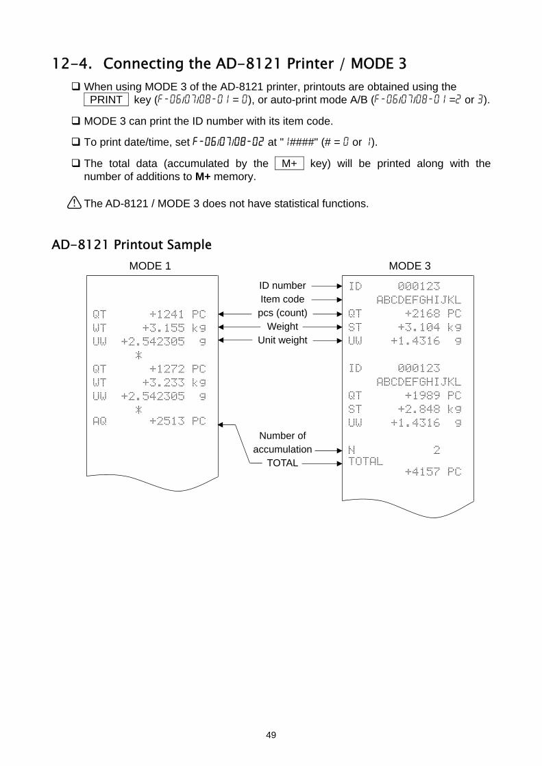
12-4. Connecting the AD-8121 Printer / MODE 3
When using MODE 3 of the AD-8121 printer, printouts are obtained using the PRINT key (f-06/07/08-01 = 0), or auto-print mode A/B (f-06/07/08-01 =2 or 3).
MODE 3 can print the ID number with its item code.
To print date/time, set f-06/07/08-02 at "1####" (# = 0 or 1).
The total data (accumulated by the M+ key) will be printed along with the number of additions to M+ memory.
The AD-8121 / MODE 3 does not have statistical functions.
AD-8121 Printout Sample
MODE 1 MODE 3
ID number Item code
pcs (count) Weight
Unit weight
Number of accumulation
TOTAL
QT +1241 PC
WT +3.155 kg
UW +2.542305 g
*
QT +1272 PC
WT +3.233 kg
UW +2.542305 g
* AQ +2513 PC
ID 000123
ABCDEFGHIJKL
QT +2168 PC
ST +3.104 kg
UW +1.4316 g
ID 000123
ABCDEFGHIJKL
QT +1989 PC
ST +2.848 kg
UW +1.4316 g
N 2 TOTAL +4157 PC
49

12-5. Command Mode
In the command mode, the scale is controlled by commands that come from an external device, computer etc.
Do not set f-06/07/08-01="1" (stream mode) to use with the command mode. if you don’t want to use command mode together with key mode or auto-print mode, set f-06/07/08-01="4" (command mode only).
Use a D-sub 9 pin cable (straight type) to connect with a computer.
Option cable: AX-KO2466-200, D-sub 9 pin, 2m Command List Command Definition Notes
@ Start / stop continuous data transmission. A Same as RESET key. Key command
D Set a known tare weight. “D,1.23CRLF” sets the tare weight as "1.23kg".
E Store the unit weight in use, other values and specified item code to ID memory.
Refer to the data format. Refer f-01-05
F Recall a unit weight from ID memory. “F123CRLF” recalls from ID000123.
G Set a known unit weight. “G,0.123CRLF” sets the unit weight as "0.123g" (or "0.123 lb").
I Same as the REMOTE SCALE key. J Same as the TOTAL key.
Key command
K Same as the M+ key. P Same as the STANDBY/OPERATE key.
Key command
Q Send data immediately. S Send stable data after accepting command.
Data depends on f-06/07/08-02
T Same as the TARE key. Key command X Request a list of the F-Function parameters. Y Request a list of the ID memory contents.
The last data terminates with <EOT> (04H)
Z Same as the ZERO key. Key command ON Turn the display ON. OFF Turn the display OFF. ?ID Send the ID number and item code in use. ?QT Send the pcs (count) data. ?WT Send the weight data. ?UW Send the unit weight in use. ?AQ Send the total (accumulated) M+ memory count
d t?AN Send the number of additions to M+ memory. ?TR Send the tare weight in use. ?MR Send the specified ID memory contents.
Refer to the data format for the reply.
50

Command Definition Notes
MR Store the unit weight and tare weight into the specified ID memory.
MI Store the item code into the specified ID memory. ML Store the comparator limits into the specified ID memory.
MA Store the total count and number of additions into the specified ID memory.
Refer to the data format for the reply.
CM Clear the specified ID memory contents “CM,1.23CRLF” clears content of id000123.
?FC Send the specified F-Function setting. FC Store the specified F-Function setting value.
Refer to the data format for the reply.
Acknowledgment and Error Codes
When the scale receives an external command, it reacts as follows:
If the command requests a data reply, the scale will send the data. For other commands, the scale will send an acknowledgment <AK> (06H) upon
acceptance of the command.
If the command is I , S , T or Z , the scale will send a second acknowledgment <AK> (06H) when the command operation is completed.
If an error occurs, the scale will send an error code.
The error format is E C , E n CR LF , "n" being the error number.
En Definition Notes E0 Communication error Parity error, framing error, etc. E1 Undefined command error The command does not exist for the scale.
E2 Scale not ready error. The scale is not in a state where a command could be expected.
E4 Too many characters error The command contains too many characters. E6 Format error The command contains invalid characters.
E7 Out of range error Value is out of range. The tare weight is more than the capacity, etc.
51

Data Format
Store the unit weight in use, other values (according to f-01-05) and specified item code
Command E , 1 2 3 C LF Stores into id000123 with no item code. E , 1 2 3 , a b c C LF Stores into id000123 with item code
" b ” Reply AK
ID number and item code Command ? I D C LF
Reply I D , 0 0 0 1 2 3 C LF A B C D E F G H I J K L C LF
I Item code (These are “space” for no item code.)
PCS (Count ) data Command ? Q T C L
Reply Q T , +
U S , - O L , +
Weight data Command ? W T C L
Reply S T , + S T , - U S , - U S , + O L , + O L , -
Unit weight Command ? U W C L
Reply U W , + U W , +
Total count Command ? A Q C L
Reply A Q , +
Accumulation number Command ? A N C L
D number
“ [ ” in examples below shows “Space” (20H).
F
0 0 0 0 1 2 3 4 [ P C C LF Stable positive data 0 0 0 0 5 6 7 8 [ P C C LF Unstable negative data9 9 9 9 9 9 9 9 [ P C C LF "E" display
F
0 0 1 . 2 3 4 6 [ k g C LF Stable positive data 0 0 2 . 7 2 5 5 [ l b C LF Stable negative data 0 0 1 2 . 3 4 6 [ l b C LF Unstable negative data0 0 0 5 . 5 9 3 [ k g C LF Unstable positive data 9 9 9 9 . 9 9 9 [ k g C LF "E" display 9 9 9 9 . 9 9 9 [ l b C LF "-E" display
F
1 . 2 3 4 5 6 7 [ [ g C LF
0 . 2 7 2 5 3 1 [ l b C LF
F
0 0 9 9 9 9 9 9 [ P C C LF
F
52

Reply A N , 0 0 0 0 1 2 3 4 C LF Tare weight Command ? T R C LF Reply T R , + 0 0 1 . 2 3 4 6 [ k g C LF
Request the scale to reply with the contents of ID memory. Command ? M R , 1 2 3 C LF Request the contents of id000123.
Reply M R , 0 0 0 1 2 3 , a b c d e f g h i j k l , 1 2 . 3 4 5 6 7 , + 0 0 0 . 2 3 4 5 , + 0 0 0 0 1 3 5 7 , + 0 0 0 0 1 2 4 6 , + 0 1 2 3 4 5 6 7 , 0 0 0 0 1 2 3 4 C LF
MR, ID number (6 digit), item code (12 digits), unit weight (8 digits including decimal point), tare weight (9 digits including sign and decimal point), upper limit (9 digits including sign), lower limit (9 digits including sign), total count (9 digits including sign), number of additions (8 digit) CR LF .
Command ? M R C LF Request the contents of the next ID.
Reply M R , 0 0 0 1 2 4 , A B C D E F G H I J K L , 2 3 . 4 5 6 7 8 , + 0 0 0 . 2 3 4 5 , + 0 0 0 0 1 3 5 7 , + 0 0 0 0 1 2 4 6 , + 0 2 3 4 5 6 7 8 , 0 0 0 0 2 3 4 5 C LF
Store the unit weight and tare weight into a specified ID memory. Command M R , 1 2 3 , 1 . 2 3 , 0 . 3 4 5 C LF
Reply AK ID number: Maximum 6 digit Unit weight: Maximum 8 digit including decimal point Tare weight: Maximum 8 digit including decimal point ("kg" or "lb"
depends on f-00 setting).
Store the item code into a specified ID memory. Command M I , 1 2 3 , a b c d C LF
Reply AK
ID Number: Maximum 6 digit Item Code: Maximum 12 digit The example above is stored as
ID # Unit weight Tare weight
ID # Item code
53
“ a b c d [ [ [ [ [ [ [ [ ”

Store the comparator limits into a specified ID memory. Command M L , 1 2 3 , + 1 0 1 0 , + 9 9 0 C LF
Reply AK ID number: Maximum 6 digit Upper limit: Maximum 9 digit including sign Lower limit: Maximum 9 digit including sign
Store the total count and number of additions into a specified ID memory. Command M A , 1 2 3 , + 6 7 8 9 , 1 2 3 C LF
Reply AK
ID # Upper Limit Lowe Limit
ID # Total Count # of Additions
ID number: Maximum 6 digits Total count: Maximum 9 digits including sign Number of addition: Maximum 8 digits Request the scale to reply with the F-Function settings. Command ? F C , 0 5 0 1 C LF Request the setting of f-05-01.
Reply F C , 0 5 0 1 , 0 C LF f-05-01 = 0
Command ? F C C LF Request to reply with the setting of the next F-Function.
Reply F C , 0 5 0 2 , 0 C LF f-05-02 = 0
Store the specified F-Function setting value Command F C , 0 5 0 3 , + 1 2 3 4 C LF Set “1234” as the Upper limit.
F-# Setting value
F-# Setting value F-Function number: 4 digits Setting value: Maximum 8 digits including sign.
Reply AK
Command O N C LF Start with new settings.
Reply AK
Having finished the "FC" command, send the "ON" command to start the scale with new settings. The scale replies <AK> (06H) and starts.
54

12-6. Using a Bar Code Reader The bar code reader can be connected to the RS-232C interface on the scale. It can read bar codes for the ID number, unit weight, tare weight and comparator limits.
Any of the RS-232C interfaces can be used for the bar code reader.
Set the F-Function f-06/07/08-01="5" to use a bar code reader. For example, to use Ch.1 (PORT 1), set f-07-01="5".
Refer to “13-1. OP-01 Bar Code Reader” about the optional bar code reader.
Requirement for the Bar Code Reader
Interface EIA RS-232C Baud rate 2400, 4800, 9600 bps Character code ASCII Terminator CR or CRLFBar code EAN/JAN, UPC, Codabar (NW-7), Interleaved 2 of 5, Code39 etc., depending on the bar code reader. Connector D-Sub 9pin connector (recommended)
In most cases, a bar code reader with an RS-232C interface is to connect directly with a personal computer. The signals must be converted to connect this kind of bar code reader with the scale. Refer to the diagram below.
RS-232C adapter or cable D-Sub 9 pin D-Sub 9 pin female connector male connector
1 1 2 2 3 3 4 4 5 5 6 6 7 7 8 8 9 9
Bar Code ReaderD-Sub 9pin
Female connector
Do not use RS-232C adapter/cable to connect the bar cod reader (OP-01) to the
RS-232C interface on the scale.
Some bar codes will have start and stop characters. But, set your bar code reader not to send those characters to the scale. The scale doesn’t accept such data.
EAN/JAN/UPC bar codes usually have a check digit and other bar codes may have either. But, set your bar code reader not to send the check digit. The scale doesn’t accept such data. If sent, the scale cannot tell the difference between data and the check digit.
55

Read the instruction/technical manual of your bar code reader to connect it with the scale.
Bar Code Data and Format
The bar code data that the scale accepts are ID number, unit weight, tare weight and comparator limits.
The bar code has "2 digit identification code + 6 digit numbers" for the ID number and "2 digit identification code + maximum 10 digit numbers including sign and decimal point" for the other data.
The unit weight and tare weight must be within 6 digits, except insignificant zeros.
Unit weight 123.456 g: “12+123.456” acceptable “12+00123.456” acceptable “12+0123.4560” not acceptable Tare weight 10 kg: “15+10” acceptable “15+0000010.0” acceptable “15+010.00000” not acceptable
The comparator limits must be within 7 digits, except insignificant zeros.
Upper limit: “17+123” acceptable “17+000000123” acceptable “17+012345670” not acceptable
Bar Code Data
Identification Code Numbers Function
ID Number 01 6 digits ID number. Recall the unit weight by ID number. Similar function to “3-5. Unit Weight By ID Number”.
Unit Weight (g) 12 10 digits including sign
and decimal point.
Enter a unit weight in “g” directly. Similar to “3-4. Unit Weight by KEYBOARD”
Unit Weight (lb) 13 10 digits including sign
and decimal point.
Enter a unit weight in “lb” directly. Similar to “3-4. Unit Weight by KEYBOARD”
Unit Weight (lb/1000pcs) 14 10 digits including sign
and decimal point.
Enter a unit weight in “lb/1000pcs” directly. Similar to “3-4. Unit Weight by KEYBOARD”.
Tare Weight (kg) 15 10 digits including sign
and decimal point.
Enter a tare weight in “kg” directly. Similar to “4-1. Using the KEYBOARD TARE key”.
Tare Weight (lb) 16 10 digits including sign
and decimal point.
Enter a tare weight in “lb” directly. Similar to “4-1. Using the KEYBOARD TARE key”.
Comparator Upper limit 17 10 digits including sign. Change comparator upper limit
temporarily.
Comparator Lower limit 18 10 digits including sign. Change comparator lower limit
temporarily.
56
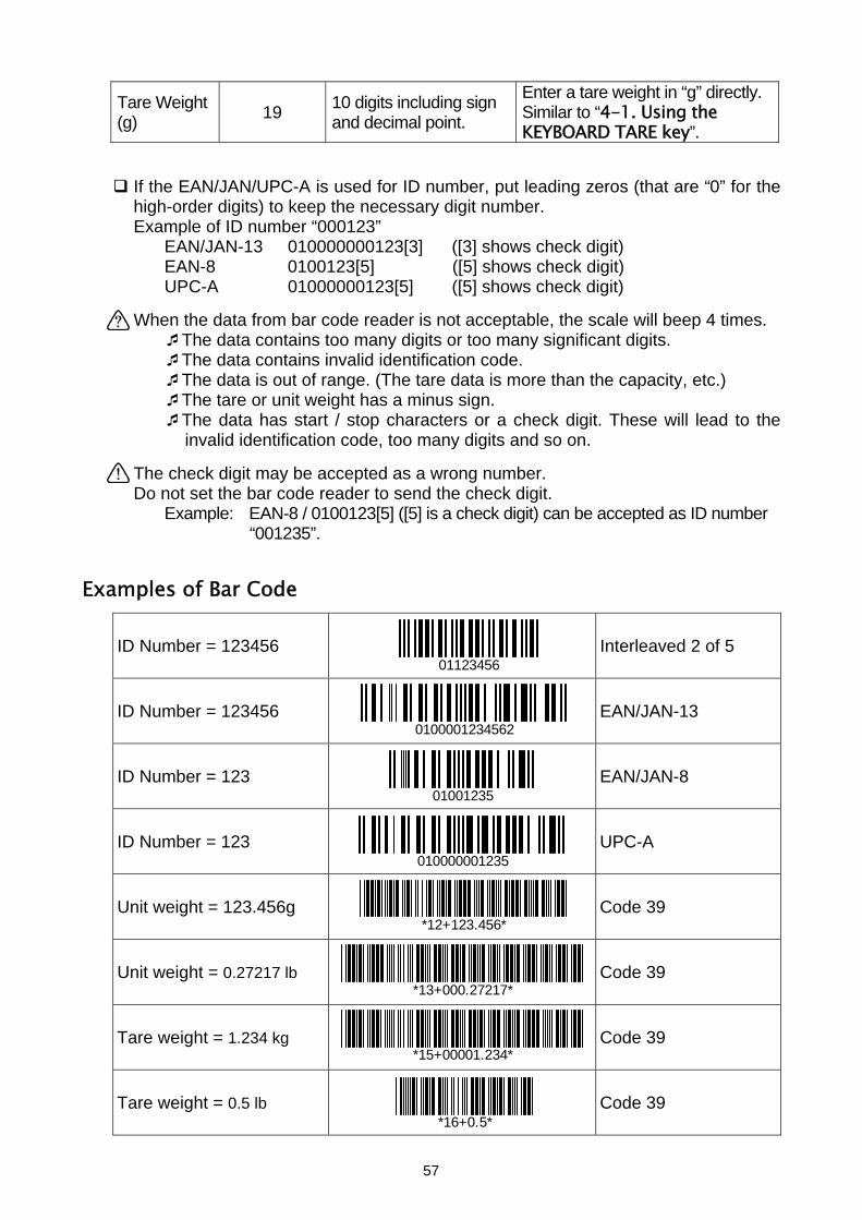
Tare Weight (g) 19 10 digits including sign
and decimal point.
Enter a tare weight in “g” directly. Similar to “4-1. Using the KEYBOARD TARE key”.
If the EAN/JAN/UPC-A is used for ID number, put leading zeros (that are “0” for the high-order digits) to keep the necessary digit number.
Example of ID number “000123” EAN/JAN-13 010000000123[3] ([3] shows check digit) EAN-8 0100123[5] ([5] shows check digit) UPC-A 01000000123[5] ([5] shows check digit)
When the data from bar code reader is not acceptable, the scale will beep 4 times.
The data contains too many digits or too many significant digits. The data contains invalid identification code. The data is out of range. (The tare data is more than the capacity, etc.) The tare or unit weight has a minus sign. The data has start / stop characters or a check digit. These will lead to the invalid identification code, too many digits and so on.
The check digit may be accepted as a wrong number. Do not set the bar code reader to send the check digit.
Example: EAN-8 / 0100123[5] ([5] is a check digit) can be accepted as ID number “001235”.
Examples of Bar Code
ID Number = 123456 Interleaved 2 of 5
ID Number = 123456 EAN/JAN-13
ID Number = 123 EAN/JAN-8
ID Number = 123 UPC-A
Unit weight = 123.456g Code 39
Unit weight = 0.27217 lb Code 39
Tare weight = 1.234 kg Code 39
Tare weight = 0.5 lb Code 39
01123456
0100001234562
01001235
010000001235
*12+123.456*
*13+000.27217*
*15+00001.234*
*16+0.5*
57

Comparator upper limit =12345 Codabar (NW-7)
A17+000012345A
58

12-7. Using UFC (Universal Flex Coms) Function
The UFC function allows you to print out as you format the printer (UFC format).
The scale can store the UFC format as text data. It will include parameters to replace with the count data, weight data and so on.
The maximum number of text data is 384 characters.
Using “PF” command, the text data has to be sent to the scale in advance. When the PRINT key is pressed or by auto-print mode A/B, the scale will send the stored text data with the parameters replaced by the original data.
Terminator for the “PF” command is "CR" or "CRLF".
The UFC format data can be sent through one RS-232C interface only. Set one of f-06/07/08-01 at "6", "7" or "8" to send the data. The others must be set at "0" ~"5" ("4" will be recommended if the other format data is not necessary to send).
Store Text Data into the Scale Memory
Command P F , $ P C , ‘ T E X T ‘ , # 2 0 , $ S P 2 , & $ C R , $ L F , $ W T , $ C R , $ L F C LF
Terminator Reply AK
The “PF” command sends text data that will include:
Parameters for the scale data and control codes
Parameter Data & Code Parameter Data & Code $PC Count $CP Comparator result $WT Weight $DT Date $UW Unit weight in use $TM Time $TR Tare weight in use $CM Comma $TL Total count $SP Space $AN Accumulation numbers $CR Carriage Return $CD ID number in use $LF Line Feed $NM Item code in use
These parameters must be used capital letters.
ASCII text string Text string is described in single quote marks as ‘Data’. The single quote itself is written as ’’(2 single quotes).
Example: Text ‘ABC’ is described as ‘’’ABC’’’.
The ASCII hexadecimal code The ASCII hexadecimal codes are written in the form “#" + 2 hexadecimal digits. This will mainly be used to send control codes that can’t be described as a text string.
59
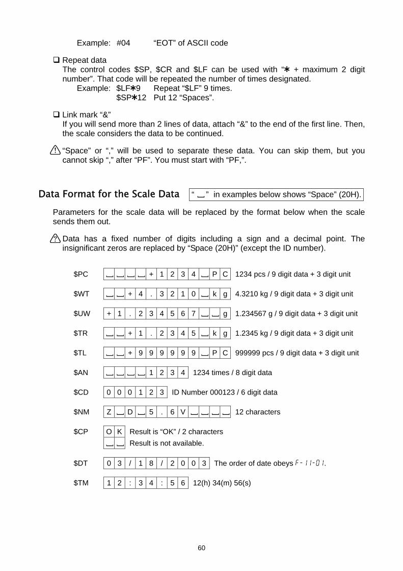
Example: #04 “EOT” of ASCII code
Repeat data The control codes $SP, $CR and $LF can be used with “ + maximum 2 digit number”. That code will be repeated the number of times designated.
Example: $LF 9 Repeat “$LF” 9 times. $SP 12 Put 12 “Spaces”.
Link mark “&” If you will send more than 2 lines of data, attach “&” to the end of the first line. Then, the scale considers the data to be continued.
“Space” or “,” will be used to separate these data. You can skip them, but you cannot skip “,” after “PF”. You must start with “PF,”.
Data Format for the Scale Data
Parameters for the scale data will besends them out.
Data has a fixed number of digitinsignificant zeros are replaced by “S
$PC [ [ [ [ + 1 2 3
$WT [ [ + 4 . 3 2 1
$UW + 1 . 2 3 4 5 6
$TR [ [ + 1 . 2 3 4
$TL [ [ + 9 9 9 9 9
$AN [ [ [ [ 1 2 3 4
$CD 0 0 0 1 2 3 ID Num
$NM Z [ D [ 5 . 6 V
$CP O K Result is “OK” / 2 c [ [ Result is not availa
$DT 0 3 / 1 8 / 2 0
$TM 1 2 : 3 4 : 5 6
“ ” in examples below shows “Space” (20H).
[ replaced by the format below when the scales including a sign and a decimal point. The pace (20H)” (except the ID number).
4 [ P C 1234 pcs / 9 digit data + 3 digit unit
0 [ k g 4.3210 kg / 9 digit data + 3 digit unit
7 [ [ g 1.234567 g / 9 digit data + 3 digit unit
5 [ k g 1.2345 kg / 9 digit data + 3 digit unit
9 [ P C 999999 pcs / 9 digit data + 3 digit unit
1234 times / 8 digit data
ber 000123 / 6 digit data
[ [ [ [ 12 characters
haracters ble.
0 3 The order of date obeys f-11-01.
12(h) 34(m) 56(s)
60

PF,‘ID~’,$CD,$CR,$LF,& ‘PN~’,$NM,$CR,$LF,& ‘Count’,$CR,$LF,&
$SP 4,$PC,$CR,$LF,&
‘Unit~Weight’,$CR,$LF,& $SP 4,$UW,$CR,$LF,&
‘Weight’,$CR,$LF,&
$SP 4,$WT,$CR,$LF,&
$CR,$LF,&
$SP 3,$DT,$CR,$LF,&
$SP 3,$TM,$CR,$LF,&
$CR,$LF,&
‘~~A&D~FC-5000i’,$CR,$LF
Terminator codes
Examples of PF command and AD-8121 Printout Sample
AD-8121 Printout “PF” Command (f-06/07/08-03=” 0” or “1”)
ID 000123
"~" shows "Space.".
Normally the printer needs to receive the terminator, and do not forget to add the terminator code(s) to the end of text data.
PN Z D 5.6V
Count
+1234 PC
Unit Weight
+1.234567 g
Weight
+1.5235 kg
03/18/2003
12:34:56
A&D FC-5000i
61

13. OPTIONS
13-1. OP-01 Bar Code Reader
The OP-01 includes a bar code reader, RS-232C cable, AC adapter (100V~240V), power plug adapter (US to European plug) and a setting-up bar code sheet.
The OP-01 bar code reader can be connected to one of the RS-232C interfaces. It can read bar codes for the ID number, unit weight, tare weight and comparator limits.
When the bar code reader reads the ID number, the scale will recall unit weight from ID memory instead of by using the ID key.
Set the F-Function f-06/07/08-01="5" to use a bar code reader. For example, to use Ch.1 (PORT 1), set f-07-01="5".
Refer to “12-6. Using a Bar Code Reader” about the bar code data and prepare bar
code labels.
The OP-01 bar code reader can be connected to one of the RS-232C interfaces. It can read bar codes for the ID number, unit weight, tare weight and comparator limits.
TRIGGER switch Triggers the bar code scanner.
Buzzer Beeps on successful read and decode.
Cable interface port for cable connecting.
LED Indicates RED as standby position. Indicates GREEN on successful read.
Scanner Window Emits light to read bar code.
• Aim the scanner at the barcode and press the trigger. • Ensure the scan line crosses every bar and space. • Do not hold the scanner directly over the barcode. • Maximum reading distance is approx. 15 mm (6 inches). WRONG
01123456
01123456RIGHT
62

Using OP-01 Bar Code Reader
1. Plug the modular connector of RS-232C cable into the port on the bottom of bar code reader, and twist the lock to the right to lock it.
2. Connect the other end of the RS-232C cable to
the RS-232C interface of the scale.
3. Plug in the AC adapter for OP-01. AC adapter jack is located at the side of the RS-232C cable connector.
Lock
RS-232C cable 4. Set the F-Function f-06/07/08-01="5"
according to the interface you connected. For example, to use Ch.1 (PORT 1), set f-07-01="5".
AC adapter plug 5. Read the next bar codes step by step, then the
bar code reader will be set to work with the scale.
This sets the RS-232C to be 9600 bps and 8 bits data / non parity. Set the F-Function f-06/07/08-04="2" and f-06/07/08-05="2". For example, to use Ch.1 (PORT 1), set f-07-04="2" and f-07-05="2".
By this set-up, the FC-i / FC-Si can accept bar codes of EAN-13/8, JAN-13/8, UPC-A/E, Codabar (NW-7), Interleaved 2 of 5 and Code 39.
The UPC-A bar code can not be used together with EAN/JAN-13. Refer to "Note 1" at "Step 4".
Note 1: When using UPC-A bar code, skip "Step 4".
STEP Set-up Bar Code Definition
Step 1 Start of configuration
Step 2 Rest to default settings
Step 3 Select RS-232C interface
Step 4 Refer to Note 1 Force UPC-A to EAN-13
Step 5 Disable transmitting UPC-A check digit
63

Step 6 Disable transmitting UPC-E check digit
Step 7 Disable transmitting EAN-13 check digit
Step 8 Disable transmitting EAN-8 check digit
Step 9 Disable transmitting CODABAR Start/Stop character
Step 10 Disable transmitting CODE 39 check digit
Step 11 Disable transmitting Interleaved 2 of 5 check digit
Step 12 End of configuration
64
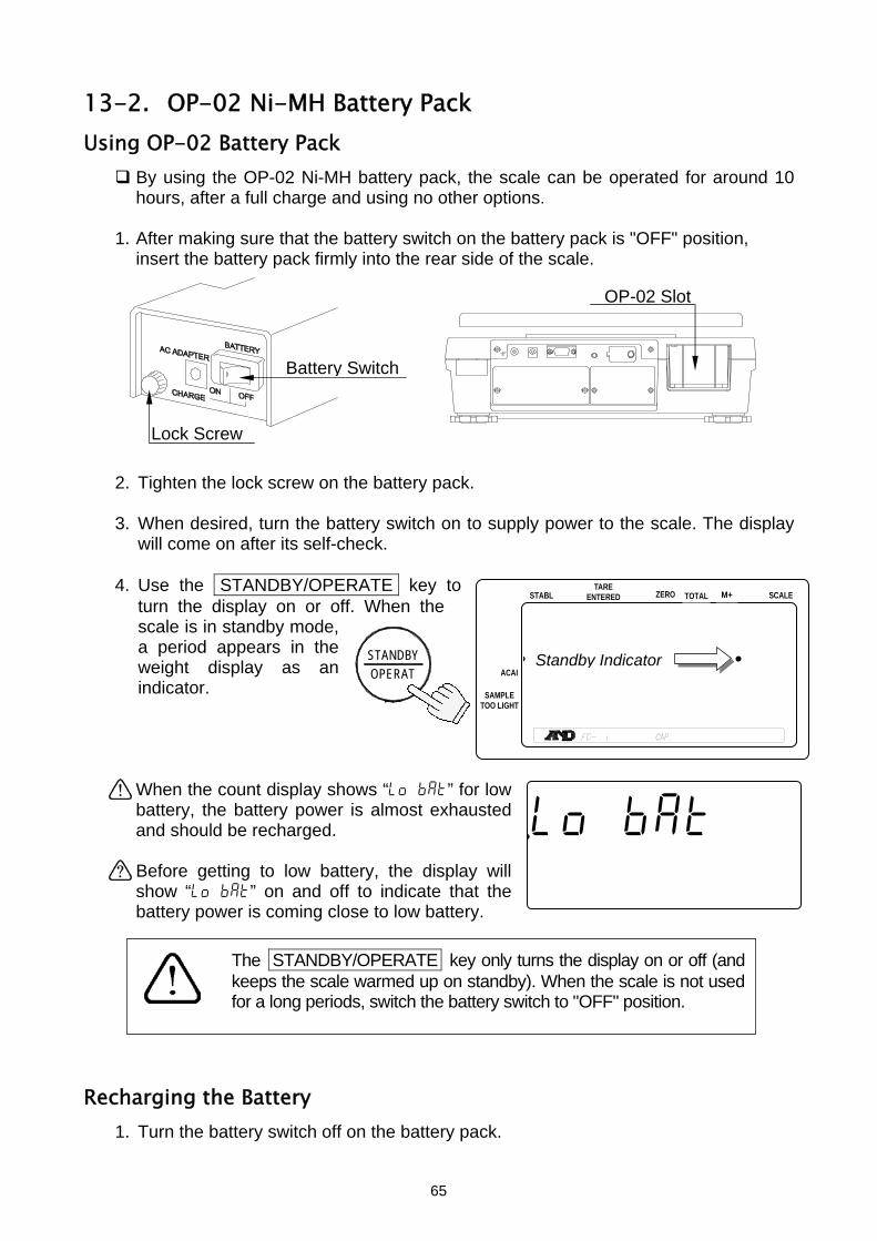
STABL
.888888 .881pcs23456789012345678901234567
12345678901234567890123456723456789012345678901234567
123456789012345678901234567
ZERO TOTAL M+TARE
ENTERED SCALE
ACAI
SAMPLE TOO LIGHT
OPERATSTANDBY Standby Indicator
.lo bat 881pcs
Calibration End Calibration weight (kg) 123456789012345678901210 .000
13-2. OP-02 Ni-MH Battery Pack Using OP-02 Battery Pack
By using the OP-02 Ni-MH battery pack, the scale can be operated for around 10 hours, after a full charge and using no other options.
1. After making sure that the battery switch on the battery pack is "OFF" position, insert the battery pack firmly into the rear side of the scale. Battery Switch
Lock Screw
OP-02 Slot
2. Tighten the lock screw on the battery pack. 3. When desired, turn the battery switch on to supply power to the scale. The display
will come on after its self-check.
4. Use the STANDBY/OPERATE key to turn the display on or off. When the scale is in standby mode, a period appears in the weight display as an indicator.
When the count display shows “lo bat” for low battery, the battery power is almost exhausted and should be recharged.
Before getting to low battery, the display will show “lo bat” on and off to indicate that the battery power is coming close to low battery.
The STANDBY/OPERATE key only turns the display on or off (and
keeps the scale warmed up on standby). When the scale is not used for a long periods, switch the battery switch to "OFF" position.
Recharging the Battery
1. Turn the battery switch off on the battery pack.
65

2. Fully loosen the lock screw and remove the battery.
If you want to recharge the battery while it is still in the scale, you may do so. In that case, disregard step 2 – but do not turn the battery switch on. If you wish to use the scale, connect another AC adapter.
3. Connect the AC adapter to the battery pack.
The battery pack will take about 15 hours to fully charge.
Charge the battery pack at a temperature between 0°C (32°F) and 40°C (104°F).
Do not charge too long as overcharging will reduce the life of batteries.
Be sure to charge the battery pack when using for the first time or if it was not used for long time (more than one month). Two or three times of recharging may be needed to reach full charge.
Be sure to use the AC adapter that is provided with the scale.
Battery switch
AC Adapter to battery pack
AC Adapter to scale Charge Scale operation
ON or OFF Connected Connected Yes Operational ON or OFF Not connected Connected No Operational
OFF Connected Not connected Yes Not operational ON Connected Not connected No Not recommended (See note)
Note The scale will be operational. After connecting the AC adapter to the battery pack, you may have to turn the battery switch OFF once and turn it ON to operate the scale.
66
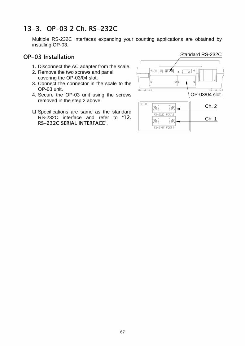
13-3. OP-03 2 Ch. RS-232C
Multiple RS-232C interfaces expanding your counting applications are obtained by installing OP-03.
OP-03 Installation Standard RS-232C
1. Disconnect the AC adapter from the scale. 2. Remove the two screws and panel
covering the OP-03/04 slot. 3. Connect the connector in the scale to the
OP-03 unit. OP-03/04 slot4. Secure the OP-03 unit using the screws
removed in the step 2 above. Ch. 2
Specifications are same as the standard RS-232C interface and refer to “12. RS-232C SERIAL INTERFACE”.
Ch. 1
67

13-4. OP-04 RS-232C and Comparator Relay Output
Multiple RS-232C interfaces and relay output for the comparator results are obtained by installing OP-04.
OP-04 Installation
See the OP-03 installation.
OP-04 is installed to the same slot as option OP-03.
The RS-232C specifications are same as the standard RS-232C interface. Refer to “12. RS-232C SERIAL INTERFACE”.
Comparator Relay Output RS-232C Ch. 1
Comparator Relay Output Circuit
Maximu
The m
M
M
M
Output connector MSTB 2.5/4-GF-5.08
Solid state relay Mating connector MSTB 2.5/4-STF-5.08 (Attached to the OP-04)L
O
H
1 COM O
2 LO 3 OK
1 2 3 4
7 mm
K 4 HI
m rating of the Relay Output aximum rating of the replay output is as follows.
aximum voltage: 50V DC
aximum current: 100mA DC
aximum ON resistance: 8Ω
Inside of the Scale
I
68
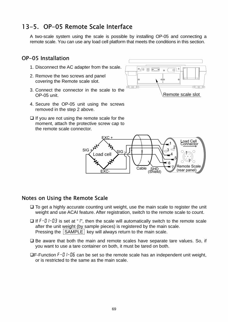
13-5. OP-05 Remote Scale Interface
A two-scale system using the scale is possible by installing OP-05 and connecting a remote scale. You can use any load cell platform that meets the conditions in this section.
OP-05 Installation
1. Disconnect the AC adapter from the scale.
2. Remove the two screws and panel covering the Remote scale slot.
3. Connect the connector in the scale to the
OP-05 unit. Remote scale slot
4. Secure the OP-05 unit using the screws removed in the step 2 above.
If you are not using the remote scale for the moment, attach the protective screw cap to the remote scale connector.
Load cell Notes on Using the Remote Scale
To get a highly accurate counting unit weight, use the main scale to register the unit weight and use ACAI feature. After registration, switch to the remote scale to count.
If f-01-03 is set at “1”, then the scale will automatically switch to the remote scale after the unit weight (by sample pieces) is registered by the main scale. Pressing the SAMPLE key will always return to the main scale.
Be aware that both the main and remote scales have separate tare values. So, if you want to use a tare container on both, it must be tared on both.
F-Function f-01-06 can be set so the remote scale has an independent unit weight, or is restricted to the same as the main scale.
69
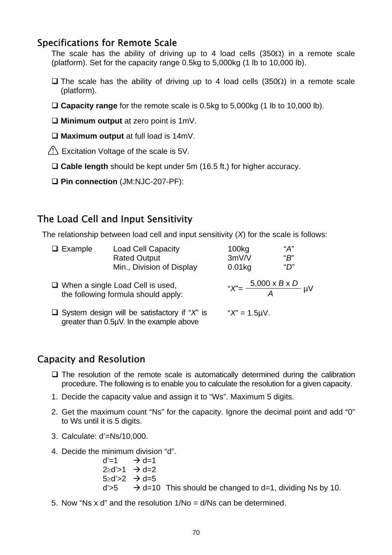
Specifications for Remote Scale The scale has the ability of driving up to 4 load cells (350Ω) in a remote scale (platform). Set for the capacity range 0.5kg to 5,000kg (1 lb to 10,000 lb).
The scale has the ability of driving up to 4 load cells (350Ω) in a remote scale (platform).
Capacity range for the remote scale is 0.5kg to 5,000kg (1 lb to 10,000 lb).
Minimum output at zero point is 1mV.
Maximum output at full load is 14mV.
Excitation Voltage of the scale is 5V.
Cable length should be kept under 5m (16.5 ft.) for higher accuracy.
Pin connection (JM:NJC-207-PF):
The Load Cell and Input Sensitivity
The relationship between load cell and input sensitivity (X) for the scale is follows:
Example Load Cell Capacity 100kg “A” Rated Output 3mV/V “B” Min., Division of Display 0.01kg “D”
5,000 x x B D
A“X”= µV When a single Load Cell is used, the following formula should apply:
System design will be satisfactory if “X” is greater than 0.5µV. In the example above
“X” = 1.5µV.
Capacity and Resolution
The resolution of the remote scale is automatically determined during the calibration procedure. The following is to enable you to calculate the resolution for a given capacity.
1. Decide the capacity value and assign it to “Ws”. Maximum 5 digits.
2. Get the maximum count “Ns” for the capacity. Ignore the decimal point and add “0” to Ws until it is 5 digits.
3. Calculate: d’=Ns/10,000.
4. Decide the minimum division “d”.
d’=1 d=1 2≥d’>1 d=2 5≥d’>2 d=5 d’>5 d=10 This should be changed to d=1, dividing Ns by 10.
5. Now “Ns x d” and the resolution 1/No = d/Ns can be determined.
70

Step Parameters Example 1 Example 2 Example 3 1 Ws 200kg 30.0kg 600kg 2 Ns 20,000 30,000 60,000 3 d’ 2 3 6 4 d 2 (=0.02kg) 5 (=0.005kg) 10 (=0.1kg)
Ns x d 20,000 x 2 30,000 x 5 6,000 x 1 5 1/No (=d/Ns) 1/10,000 1/6,000 1/6,000
6. Calculate the voltage sensitivity “Es”. Es = (As-Ao) x 5,000 x 1/No (µV) [5,000 means excitation voltage 5V] Ao: Load cell output at zero point (mV/V) As: Load cell output at full capacity (mV/V)
7. Check the voltage sensitivity “Es”.
Es≥0.5µV Calculated “Ns x d” is fixed. In example 3 in the step 5, a 600kg x 0.1kg scale will be obtained.
Es<0.5µV Change “d” for new resolution 1/No. d=1 2 d=2 5 d=5 10 1 (dividing “Ns” by 10)
In example 1, the new d=5: 1/No=d/Ns=5/20,000=1/4,000 (200kg x 0.05kg)
In example 2, the new d=1 and Ns=3,000: 1/No=d/Ns=1/3,000 (30kg x 0.01kg)
Using the new 1/No, go to step 6 and repeat it until Es≥0.5µV in step 7.
Remote Scale kg/lb relationship
When the capacity was set by “kg”: Let capacity x minimum division = Ws x Wd (kg) When:
d = 1, then Wd (lb) = Wd (kg) x 2 d = 2, then Wd (lb) = Wd (kg) x 5/2 d = 5, then Wd (lb) = Wd (kg) x 2
And: Ws (lb) = Wd (kg) x No
Example: 15kg x 0.002kg, No = 15kg/0.002kg =7,500 Wd (lb) = 0.002 x 5/2 = 0.005 (lb) Ws (lb) = 0.005 (lb) x 7,500 = 37.5 (lb)
When the capacity was set by “lb”:
Let capacity x minimum division = Ws x Wd (lb) When:
d = 1, then Wd (kg) = Wd (lb) x 1/2 d = 2, then Wd (kg) = Wd (lb) x 1/2 d = 5, then Wd (kg) = Wd (lb) x 2/5
And: Ws (kg) = Wd (lb) x No
Example: 30lb x 0.005lb, No = 30lb/0.005lb =6,000
71
USA Version ONLY

Wd (kg) = 0.005 x 2/5 = 0.002 (kg) Ws (kg) = 0.002 (kg) x 6,000 = 12 (kg)
Calibrating the Remote Scale
When a remote scale is newly connected, set the capacity and calibrate the scale using a weight.
The scale must be warmed up (plugged in) for at least 30 minutes before starting calibration.
1. Remove the calibration switch cover, and
press the calibration CAL switch. The scale shows “CAL” in the count display.
Press the CAL switch to exit without calibrating the scale.
2. Press the REMOTE SCALE key to display SCALE “2”.
When SCALE “1” is displayed, press the REMOTE SCALE key again.
Once the remote scale has been calibrated, the display will go to step 4.
3. Use the 0 9 and . 10-key pad to display the desired capacity. (Example of capacity 2000kg)
4. Press the ENTER key. The capacity value stops blinking.
When the remote scale has been changed or to change capacity, go back to step 3.
5. Press the ENTER key again to store the capacity entered and the remote scale is ready to be calibrated.
.88Cal10881pcs
[ZERO] Calibration 1234567890123 [TARE] Gravity Acceleration1234567890123
.88Cal10882pcs
Maximum Capacity (kg) Cal4567890123aaaaaaaaa10 .000[TARE] Gravity Acceleration1234567890123
SCALE “1”: Main Scale SCALE “2”: Remote Scale
ENTER
.88Cal10882pcs
Maximum Capacity (kg) Cal4567890123aaaaaaaaa12000[TARE] Gravity Acceleration1234567890123
TUV
DEFABC
MNO
6
1
7 8PQRS
2 3JKLGHI
09WXYZ
4
#
5
C
.
.88Cal10882pcs
Maximum Capacity (kg) Cal4567890123aaaaaaaaa2000 .0[TARE] Gravity Acceleration1234567890123
ENTER
.88Cal10882pcs
[ZERO] Calibration 1234567890123 [TARE] Gravity Acceleration1234567890123
72

6. Go to step 2 in section “9-1. Calibration Procedure Using a Weight” to calibrate the remote scale.
14. SPECIFICATIONS MODEL FC-500i FC-1000i FC-2000i FC-5000i FC-10Ki FC-20Ki FC-50KiCapacity (k)g 500 g 1 kg 2 kg 5000 g 10 kg 20 kg 50 kgResolution (k)g 0.05 g 0.1 g 0.2 g 0.5 g 1 g 2 g 5 gCapacity lb 1 lb 2 lb 5 lb 10 lb 20 lb 50 lb 100 lbResolution lb 0.0001 lb 0.0002 lb 0.0005 lb 0.001 lb 0.002 lb 0.005 lb 0.01 lbSample Size 10 pieces normal – 5, 25, 50, 100 or random number, user selectable Min. Unit Weight (Normal mode) 0.01 g 0.02 g 0.04 g 0.1 g 0.2 g 0.4 g 1 g
Min. Unit Weight (Fine mode) 0.0005 g 0.001 g 0.002 g 0.005 g 0.01 g 0.02 g 0.05 g
Non-linearity ±0.05 g ±0.1 g ±0.2 g ±0.5 g ±1 g ±2 g ±5 g Repeatability 0.05 g 0.1 g 0.2 g 0.5 g 1 g 2 g 5 g Span Drift 0.002%/°C (5°C~35°C) typ. Operating Temp. -10°C to 40°C/14°F to 104°F, less than 85%R.H. (No Condensation) Display 7 segment / 5x7 dot VFD Display Update Approximately 10 times per second Interface RS-232C (1ch.) standard, Maximum 3 ch. with optional interface
Power AC adapter or Optional Ni-MH Battery Pack Battery Operating Time: Approx. 10 hours (main scale only)
Platform Size 205 x 152 (mm) 8.1 x 6.0 (inches)
315 x 270 (mm) 12.4 x 10.6 (inches)
Dimensions (W) x (D) x (H)
330 x 462 x 107 mm 13.0 x 18.2 x 4.2 inches
330 x 462 x 117 mm 13.0 x 18.2 x 4.6 inches
Weight (approx.) 5.5 kg 5.5 kg 6.5 kg 6.7 kg 6.7 kg 6.7 kg 7.5 kg
Calibration Weight 500 g ± 0.01 g
1 kg ± 0.02 g
2 kg ± 0.05 g 5kg±0.1g 10kg±0.2g 20kg±0.5g 50kg±1g
Accessories This manual, AC adapter
73
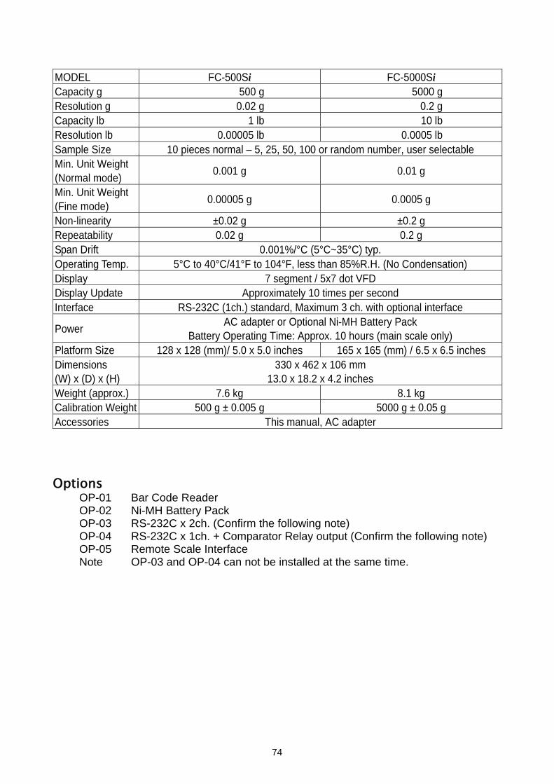
MODEL FC-500Si FC-5000Si Capacity g 500 g 5000 g Resolution g 0.02 g 0.2 g Capacity lb 1 lb 10 lb Resolution lb 0.00005 lb 0.0005 lb Sample Size 10 pieces normal – 5, 25, 50, 100 or random number, user selectable Min. Unit Weight (Normal mode) 0.001 g 0.01 g
Min. Unit Weight (Fine mode) 0.00005 g 0.0005 g
Non-linearity ±0.02 g ±0.2 g Repeatability 0.02 g 0.2 g Span Drift 0.001%/°C (5°C~35°C) typ. Operating Temp. 5°C to 40°C/41°F to 104°F, less than 85%R.H. (No Condensation) Display 7 segment / 5x7 dot VFD Display Update Approximately 10 times per second Interface RS-232C (1ch.) standard, Maximum 3 ch. with optional interface
Power AC adapter or Optional Ni-MH Battery Pack Battery Operating Time: Approx. 10 hours (main scale only)
Platform Size 128 x 128 (mm)/ 5.0 x 5.0 inches 165 x 165 (mm) / 6.5 x 6.5 inches Dimensions (W) x (D) x (H)
330 x 462 x 106 mm 13.0 x 18.2 x 4.2 inches
Weight (approx.) 7.6 kg 8.1 kg Calibration Weight 500 g ± 0.005 g 5000 g ± 0.05 g Accessories This manual, AC adapter Options
OP-01 Bar Code Reader OP-02 Ni-MH Battery Pack OP-03 RS-232C x 2ch. (Confirm the following note) OP-04 RS-232C x 1ch. + Comparator Relay output (Confirm the following note) OP-05 Remote Scale Interface Note OP-03 and OP-04 can not be installed at the same time.
74
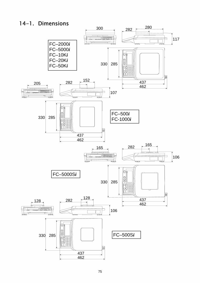
14-1. Dimensions
280 300 282
117FC–2000i FC–5000i FC–10Ki FC–20Ki FC–50Ki 285330
152462 437 282 205
107
FC–500i FC-1000i 285 330
462437
165 282165
106
FC–5000Si 285330
128
FC–500Si
462 437 282 128
106
285 330
462437
75

15. GRAVITY ACCELERATION MAP Values of gravity at various locations
Amsterdam 9.813 m/s2 Manila 9.784 m/s2
Athens 9.807 m/s2 Melbourne 9.800 m/s2
Auckland, NZ 9.799 m/s2 Mexico City 9.779 m/s2
Bangkok 9.783 m/s2 Milan 9.806 m/s2
Birmingham 9.813 m/s2 New York 9.802 m/s2
Brussels 9.811 m/s2 Oslo 9.819 m/s2
Buenos Aires 9.797 m/s2 Ottawa 9.806 m/s2
Calcutta 9.788 m/s2 Paris 9.809 m/s2
Cape Town 9.796 m/s2 Rio de Janeiro 9.788 m/s2
Chicago 9.803 m/s2 Rome 9.803 m/s2
Copenhagen 9.815 m/s2 San Francisco 9.800 m/s2
Cyprus 9.797 m/s2 Singapore 9.781 m/s2
Djakarta 9.781 m/s2 Stockholm 9.818 m/s2
Frankfurt 9.810 m/s2 Sydney 9.797 m/s2
Glasgow 9.816 m/s2 Taichung 9.789 m/s2
Havana 9.788 m/s2 Taiwan 9.788 m/s2
Helsinki 9.819 m/s2 Taipei 9.790 m/s2
Kuwait 9.793 m/s2 Tokyo 9.798 m/s2
Lisbon 9.801 m/s2 Vancouver, BC 9.809 m/s2
London (Greenwich) 9.812 m/s2 Washington, DC 9.801 m/s2
Los Angeles 9.796 m/s2 Wellington, NZ 9.803 m/s2
Madrid 9.800 m/s2 Zurich 9.807 m/s2
76

World map
77
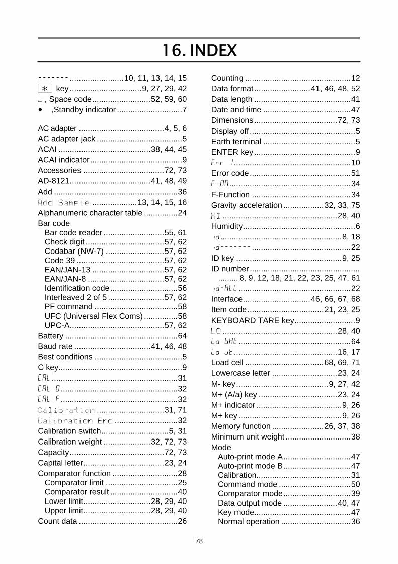
16. INDEX -------........................10, 11, 13, 14, 15 key ................................9, 27, 29, 42 ~ , Space code..........................52, 59, 60
,Standby indicator .............................7 AC adapter ......................................4, 5, 6 AC adapter jack ......................................5 ACAI .........................................38, 44, 45 ACAI indicator.........................................9 Accessories ....................................72, 73 AD-8121....................................41, 48, 49 Add .......................................................36 Add Sample ....................13, 14, 15, 16 Alphanumeric character table ...............24 Bar code
Bar code reader ...........................55, 61 Check digit ...................................57, 62 Codabar (NW-7) ..........................57, 62 Code 39 .......................................57, 62 EAN/JAN-13 ................................57, 62 EAN/JAN-8 ..................................57, 62 Identification code..............................56 Interleaved 2 of 5 .........................57, 62 PF command .....................................58 UFC (Universal Flex Coms) ...............58 UPC-A..........................................57, 62
Battery ..................................................64 Baud rate ..................................41, 46, 48 Best conditions .......................................5 C key.......................................................9 Cal........................................................31 Cal 0....................................................32 Cal f....................................................32 Calibration ..............................31, 71 Calibration End ............................32 Calibration switch..............................5, 31 Calibration weight .....................32, 72, 73 Capacity..........................................72, 73 Capital letter....................................23, 24 Comparator function .............................28
Comparator limit ................................25 Comparator result ..............................40 Lower limit..............................28, 29, 40 Upper limit..............................28, 29, 40
Count data ............................................26
Counting ...............................................12 Data format .........................41, 46, 48, 52 Data length ...........................................41 Date and time .......................................47 Dimensions.....................................72, 73 Display off ...............................................5 Earth terminal .........................................5 ENTER key.............................................9 err 1....................................................10 Error code.............................................51 f-00......................................................34 F-Function ............................................34 Gravity acceleration ..................32, 33, 75 HI ...................................................28, 40 Humidity..................................................6 id......................................................8, 18 id-------............................................22 ID key ...............................................9, 25 ID number.................................................
......... 8, 9, 12, 18, 21, 22, 23, 25, 47, 61 id-all..................................................22 Interface..............................46, 66, 67, 68 Item code..................................21, 23, 25 KEYBOARD TARE key...........................9 LO ...................................................28, 40 lo bat..................................................64 lo ut..............................................16, 17 Load cell ...................................68, 69, 71 Lowercase letter .............................23, 24 M- key.........................................9, 27, 42 M+ (A/a) key ...................................23, 24 M+ indicator ......................................9, 26 M+ key ..............................................9, 26 Memory function .......................26, 37, 38 Minimum unit weight .............................38 Mode
Auto-print mode A..............................47 Auto-print mode B..............................47 Calibration..........................................31 Command mode ................................50 Comparator mode..............................39 Data output mode ........................40, 47 Key mode...........................................47 Normal operation ...............................36
78

Operating mode .............................7, 36 Simple operation................................36 Simple operation mode........................7 Standby mode......................................7 Stream mode .....................................47
Net weight.............................................19 no id....................................................18 Numerical keys ...........................9, 23, 24 OK ..................................................28, 40 OP-01 ...................................................61 OP-02 ...................................................64 OP-03 ...................................................66 OP-04 ...................................................67 OP-05....................................................68 Operating mode ....................................36 Operating temperature................6, 72, 73 Parity...............................................41, 46 pcs...................13, 14, 15, 16, 44, 45, 47 Power..............................................72, 73 PRINT key ........................................9, 24 Printer .............................................48, 49 Remote scale......5, 36, 37, 44, 68, 69, 70 REMOTE SCALE key .............................9 RESET key .......................................9, 12 Resolution.......................................72, 73 RS-232C...................5, 46, 55, 61, 66, 67 SAMPLE key.............9, 13, 14, 15, 16, 17 Sample size ......13, 14, 15, 16, 17, 72, 73 SAMPLE TOO LIGHT indicator ..............9 Second..................................................30 Self-check ...............................................5 Signal input ...........................................42 Slot
OP-02 ............................................5, 64 OP-03/04 .......................................5, 66 Remote scale......................................68
Span calibration ....................................32 Spirit level ...............................................5
Stable detection speed .........................39 STABLE indicator ...................................9 Standby indicator ..............................7, 10 STANDBY/OPERATE key ........5, 7, 9, 64 Start bit .................................................46 Stop bit .................................................46 STORE UNIT WEIGHT key ......................
.....................................9, 21, 22, 23, 24 TARE ENTERED indicator .........9, 11, 19 TARE key ...................................9, 11, 19 Tare operation ......................................19 Tare weight ...........................................25 Terminator ............................................46 Time and date.................................30, 43 Total count ......................................25, 27 TOTAL indicator................................9, 27 TOTAL key............................9, 24, 26, 27 Total weight ..........................................13 Unit .....................................................7, 8
kg...................................................7, 36 Kilogram ........................................7, 36 lb ....................................................7, 36 Pounds ..........................................7, 36 Weighting unit ................................7, 36
Unit weight ................................................8, 12, 13, 14, 15, 16, 17, 18, 21, 22, 25, 37, 44, 45, 47, 72, 73 Minimum unit weight ..........................38 UW(g) .........8, 9, 13, 14, 18, 21, 44, 45 UW(lb)...............................................7
Warm up .......................................5, 6, 31 Weighing pan..........................................5 Weight ............................................72, 73 Zero calibration .....................................32 ZERO indicator .................................9, 10 ZERO key .........................................9, 10 Zero tracking...................................10, 39
79

MEMO
80

MEMO
81

------- key ~ , Space code
,Standby indicator
82

