coupled thermal-mechanical-hydrological behaviour of ... · nguyen and selvadurai: tmh study of...
TRANSCRIPT

hr. .I. Rock MecA. Min. Sci. & Geomeclt. Ahsfr. Vol. 32. No. 5. DD. 465479. 1995
> Pergamon 0148-9062(95)00036-4
. . . Copyright ,Q 1995 Elsevier Science Ltd
Printed in Great Britain. All rights reserved 014%9062195~S9.50 + 0.00
Coupled Thermal-Mechanical-Hydrological Behaviour of Sparsely Fractured Rock: Implications for Nuclear Fuel Waste Disposal T. S. NGUYEN? A. P. S. SELVADURAIS
This paper summarizes research activities on thermal-mechanical-hydrological (TMH) coupling and its implications on nuclear fuel waste disposal in sparsely
fractured plutonic rocks. These research activities include the development of aJinite element computer code, FRACON, its vertjication against analytical solutions, its calibration against laboratory and field experiments initiated by the Atomic Energy Control Board (AECB) and performed at Carleton and McGill Universities, and the AECB’s participation in the DECOVALEX international project. The FRACON code was used in the preliminary analysis of the coupled TMH response of a sparsely fractured rock mass around a hypothetical nuclear fuel waste repository. It was found that the flow and structural characteristics of this rock mass could be sign@cantly perturbed by the thermal pulse generated by the wastes. The implications of these pertur- bations on the safety of the disposal system have to be further quantijied.
1. INTRODUCTION
In Canada, nuclear fuel waste (NFW) disposal in sparsely fractured plutonic rocks is being currently pro- posed by Atomic Energy of Canada Ltd (AECL) [I]. The geological barrier is a major one in that proposal [2]. The performance of the geological barrier ultimately depends on its groundwater regime. Since the wastes will generate heat for hundreds to thousands of years, the stability, deformation and water flow characteristics of the rock mass will be influenced by the introduced thermal pulse. To develop plausible models of coupled thermal- hydrological-mechanical (THM) processes in geological media, it is desirable to consider the characteristics of both the intact rock and discontinuities such as fracture zones that are usually present in massive geological formations. An extensive literature review has shown that the study of coupled THM processes in porous, sparsely fractured geological media, such as granitic rock of the Canadian Shield are still in a relatively early stage of theoretical and experimental development. Specific questions of interest could include the following aspects:
(i) The progress in code development of THM coupled processes has been hindered by the scarcity of both available analytical solutions to perform verification, and experimental data to
tAtomic Energy Control Board, Wastes and Impacts Division, 280 Slater, Ottawa, Ontario, Canada KIP 59.
SMcGill University, Montreal, Canada H3A 2K6.
(ii)
(iii)
(iv)
perform calibration/validation. This fact has been widely recognized by many researchers [3-81. Conversely, the design of laboratory of in situ experiments and the interpretation of the results are problematic without adequate mathematical models capable of simulating the experiments. Thus, computational modelling and experimental modelling should be regarded as complementary endeavours. Although Terzaghi’s and Biot’s [9, lo] theories of isothermal consolidation have been successfully used to predict certain aspects of the consoli- dation behaviour of soils, more studies are needed in order to extend these theories to sparsely jointed rocks, especially in the non- isothermal range. In order to handle complex geometries and boundary conditions, numerical methods, such as the finite element, boundary integral element or discrete element methods, need to be developed. The finite element method is the computational modelling procedure that is most widely used by engineers. With finite element modelling of non- isothermal consolidation problems, numerical difficulties, in the form of spatial and temporal oscillations of the solutions, could be experienced.
The Atomic Energy Control Board (AECB) is the Canadian agency responsible for the regulation of the
465

466 NGUYEN and SELVADURAI: TMH STUDY OF SPARSELY FRACTURED ROCK
nuclear industry in Canada. In order to independently assess the implications of THM coupling on NFW disposal in sparsely fractured plutonic rocks, as being currently proposed by AECL, the AECB has initiated a research program, in cooperation with Carleton University and McGill University which consists of two main phases:
0)
(ii)
Develop a finite element code, FRACON, with a variety of element capabilities which can examine THM processes in both solid media and in dis- continuities. Verify the code against analytical solutions and calibrate/validate the code against laboratory and field experiments. Simulate the coupled THM behaviour of a hypo- thetical NFW repository. Perform parametric studies to examine the influences of jointing, stress-dependence of permeability, nonlinear stress-strain behaviour (particularly for fractures and joints), etc. on the performance of the hypo- thetical NFW repository.
In this paper, we will present the progress achieved to date in the above research programme.
2. GOVERNING EQUATIONS OF COUPLED THM PROCESSES IN SATURATED GEOLOGICAL MEDIA-
FINITE ELEMENT FORMULATION
By generalizing Biot’s theory of consolidation to include thermal effects, we can obtain the following equations governing the non-isothermal consolidation of saturated porous media [l 11:
(1) a -
aXi
+[(l -a)B -(l -n)/3,-nBr]~=0 (3)
where the unknowns are the displacement ui (m), tem- perature T (“C) and pore pressure p (Pa), “ij is the thermal conductivity tensor of the bulk medium (W/m/C), p is the density of the bulk medium (kg/m3), C is the specific heat per unit mass of the bulk medium (J/kg/C), G and I are the Lame’s constants (Pa), a = 1 - KD JK,, K,, KS and Kf are, respectively, the bulk modulii of the drained material, the solid phase and the fluid phase (Pa), 4 is the volumetric body force (N/m3), @, /?I and pf are, respectively, the coefficient of thermal expansion of the drained material, the solid phase and the fluid phase (“C-‘), n is the porosity of the medium
(dimensionless), pf is the density of the fluid (kg/m3), p is the viscosity of the fluid (kg/m/set), k, is the intrinsic permeability tensor (m’) and gi is the ith component corresponding to the acceleration due to gravity (m/set’).
In the above equations, the Cartesian tensor notation, with Einstein’s summation convention on repeated indices is adopted. In addition, the sign convention for stress and fluid pressure is considered positive for tension fields. In developing these equations, we invoke the basic principles of continuum mechanics (namely conservation of mass, momentum and energy). These principles are universally applicable, independent of the nature of the medium being considered. Also, in order to arrive at a set of equations in which the number of unknowns equals the number of equations, the following additional assumptions are necessary:
(i) Darcy’s law governing pore fluid flow. Darcy’s law is applicable with reasonable accuracy to almost all types of geological materials [ 121 including soils and rocks, provided that the hydraulic gradients are within the laminar flow range, and above a threshold gradient within which the pore fluid is virtually immobile.
For most geotechnical applications, the pore fluid is water at a constant temperature, and the original form of Darcy’s law is appropriate. Where thermal effects are important, and/or the pore fluid is not water, Darcy’s law has to be modified [13], i.e.:
Vif, vi, are the velocities, respectively, of the fluid and the solid (m/s).
The use of the generalized Darcy’s law (4) is essential when one deals with fluids other than water. It is thus necessary to separate the expression for the hydraulic conductivity Kij (loosely referred to as the permeability in most geotechnical applications) into a fluid indepen- dent component k,, and a fluid dependent component characterized by its viscosity and density, i.e.:
K. =pfgk. D
P “’ (5)
The viscosity and density of a particular fluid are also strongly temperature-dependent. When thermal effects are considered, appropriate experimentally derived func- tions of temperature should be used for these two properties.
(ii) A generalized principle of effective stress is adopted. Several forms of this principle exist [14,15]. We adopt the form of generalized prin- ciple of effective stress formulated by Zienkiewicz et al. [15]. In contrast to Terzaghi’s principle of effective stress [9], this generalized principle takes into consideration the compressibility of the pore fluid and the solid phases. Omission of the com- pressibility of the pore fluid and the solid phase could lead to an overprediction of pore pressures in competent rocks [I 11.

NGUYEN and SELVADURAI: TMH STUDY OF SPARSELY FRACTURED ROCK 461
(iii)
(iv)
Hooke’s law for linear isotropic elastic behaviour of the porous skeleton is adopted. This is a useful first approximation for the study of intact com- petent rocks which are subjected to stress states below those which could initiate fracture, failure or damage. More sophisticated constitutive relationships could be introduced and these will be considered in the future developments of this work. Heat conduction is assumed to be the predomi- nant mechanism of heat transfer. In a geological medium, there are two dominant mechanisms of heat transfer-heat conduction and heat convec- tion. Heat conduction is the transfer of heat by the activation of solid and fluid particles, without their bulk movement. The conduction of heat is governed by Fourier’s law, which states that the rate of heat flow is proportional to the tempera- ture gradient. Heat convection on the other hand is due to the bulk motion of the particles. In a poro-elastic medium, the movement or displace- ment of the solid particles could be neglected; thus it is the fluid flow which is primarily respon- sible for the convective heat transfer. The rate of heat transfer by convection is proportional to the rate of fluid flow. It could be shown that for low permeability geological media, such as granitic rock masses, since the rate of fluid flow is sufficiently slow, heat transfer by convection is usually negligible in comparison to heat transfer by conduction.
We assume that conduction is the main mechanism of heat transfer, and that Fourier’s law applies. We also assume that a state of thermal equilibrium always exists between the fluid and the solid (i.e. at any point, the temperature of the solid equals the temperature of the fluid).
The governing equations are approximated by matrix equations via a standard Galerkin finite element pro- cedure [13]. Let us consider a domain R with boundary B where the above equations apply. Considering standard finite element procedures, the domain R is
n
L k+k i
X
X
Fig. 2. Joint element.
discretized in N, elements. Two types of elements are considered:
Plane isoparametric elements. This element (Fig. 1) is used to represent the unfractured rock mass. Displace- ments within the element are interpolated as functions of the displacements at all eight nodes, while the pore pressure and temperature are interpolated as functions of the same values at only the four corner nodes i, k, m and o. A detailed description of this element is given, for example, by Smith and Griffiths [16].
Joint element. This element (Fig. 2) is used to simulate discontinuities in the rock mass such as joints, fracture zones, and fault zones. In finite element terminology [17-211, it is a very thin element, characterized by a thickness b and length L. Nodal displacements are obtained at all six nodes (Fig. 2) while nodal pore pressures and temperatures are obtained only at the corner nodes i, k, 1 and n. The mechanical behaviour of the element is dictated by its shear and normal stiffnesses D,,,, and D,,,, , respectively, and its hydraulic and thermal behaviour are governed by the transverse and longi- tudinal permeabilities k,.,. and k,,., and the transverse and longitudinal thermal conductivities k,,,, and k,,. , respectively.
Free draining
l’r Impermeable
Fig. 3. Finite element mesh for one-dimensional isothermal consolidation. Fig. 1. Solid isoparametric element.

468 NGUYEN and SELVADURAI: TMH STUDY OF SPARSELY FRACTURED ROCK
With the above two types of elements being fully defined, a Galerkin procedure is applied to the differen- tial equations (lH3) of non-isothermal consolidation. One then obtains the matrix equations of the form:
P[KHl + WIW[CMlI{T)’ = iFHI + {FQ) +W - 1)[KKl+ WIW~CMII~T~” (6)
Fl a PI w a [CP]’ -fIAt[KP] - c,[CM] II I {p}’ = if1
(1 - tI)At[KP] - c,[CM]
where the unknown are the nodal displacements {d}‘, the nodal temperatures {T}’ and the nodal pore pressures {p}’ at the current time step, {a}‘, {T}’ and {p}” are the nodal displacements, nodal temperatures, and nodal pore pressures at the previous time step, {f} is the “force” vector, {FQ} and {FH} are heat flux vectors, 8 is a time integration constant all the other matrices, p], [CP], etc. are assembled from element matrices, which are dependent on thermal, mechanical and hydrological properties of the individual elements and the inter- polation functions used. Also
c, = n/Kf- n/K, + a/KS
The time integration constant 8 varies between 0 and 1. Using a value of 8 = 0.75, we observe that after the first few three or four time steps, stability of the solution is generally reliably achieved [22].
1.5
1.0
,g a
0.5
0.0
3. CODE VERIFICATION
For isothermal cases, analytical solutions for one- dimensional consolidation are given by Terzaghi [9], for two-dimensional plane strain or axisymmetric iso- thermal consolidation results are given by McNamee and Gibson [23]. References to further studies are given by Selvadurai and Yue [24]. To our knowledge, the only analytical solution under transient conditions and in- cluding thermal effects is that given by Booker and Savvidou [25] for the consolidation of an infinite porous medium due to a volumetric heat source. In this chapter we will perform verification of the FRACON code by means of comparison with the above analytical sol- utions. It is considered that the problems that follow would constitute a useful set of benchmark problems for testing the accuracy of computer codes similar to FRACON.
3.1. One-dimensional isothermal consolidation Terzaghi [9] provided an analytical solution for the
problem of one-dimensional consolidation of a soil column of thickness H, with an impermeable base and loaded at the surface with a constant pressure po. The finite element mesh and the boundary conditions for this problem is shown in Fig. 3. The following material parameters are used in the finite element analysis:
E=35x 1O’Pa
v = 0.2
K = lo-” m/set.
The load at the surface is assumed to be:
p,=3Ox 106Pa
FE - z/H =0.579
FE-z/H=O.1@4
Analytic - z/H 4.579
Analytic - z/H =0.104
Fig. 4. Pore pressure evolution at different depths.

NGUYEN and SELVADURAI: TMH STUDY OF SPARSELY FRACTURED ROCK 469
0.4
0.3
5 5 0.2 c3
Fig. 5. Vertical settlement of the surface.
Node 15 *
Node91 /
a J-
0 FE
Analytical result
, I , ,
Impermeable
Impermeable b
x or r
Finite element mesh dimension 50000 mx50000 m Node 9 : x=0 z=45071 Node 15: x=0 z=37776 Node 91: x=5669 2~36776
Fig. 6. Finite element mesh for consolidation of a half-space under plane strain or axisymmetric conditions.

470 NGUYEN and SELVADURAI:
and the thickness H is:
H = 5000 m.
TMH STUDY OF SPARSELY FRACTURED ROCK
and c, is the coefficient of consolidation, which is related to the hydraulic conductivity K and the elastic constants by:
KE(1 -v)
The normalized pore pressure p/p0 vs the normalized c, =
P&(1 - 2v)(l + v) (9)
time T at two different depths z, is shown in Fig. 4, where:
where g is the acceleration of gravity and pr is the density of the pore fluid.
Except for some initial oscillations for the first three
T=$ (8) of four time steps, Fig. 4 shows that the finite element results agree very accurately with the analytical solution.
a) plane strain
Node 9(anaIytic result) 0.6
---.~~~~ Node 15(analy& result)
& ------- Nude 9l(analytic result)
0.4 QI A Node 9 (FE)
??0.2
Nude 15 (FE)
0 Node 91 (FE)
0
T
b) Axisymmetric
0.1 Node 9l(analytical result)
& ----... Node lS(analytical result)
\ a Node 15 (FE)
0.05 Node 9 1 (FE)
0
5 B s G e $ g !3
H 8 ?
c g i% g CI c( 2 i i
T
Fig. 7. Plane strain and axisymmetric conditions-pore pressure evolution.
NGUYEN and SELVADURAI: TMH STUDY OF SPARSELY FRACTURED ROCK 471
The normalized surface settlement Gw/po/H (where G is the shear modulus and w is the absolute settlement) is shown as a function of time in Fig. 5. The agreement between the finite element and the analytical solutions is excellent.
T = Etla’with E = 2KGlp,/g and K is the hydraulic conductivity. Also,
3.2. Isothermal consolidation of a semi-infinite medium under plane strain and axisymmetric conditions
McNamee and Gibson [23] derived analytical sol- utions for both plans strain and axisymmetric problems of isothermal consolidation of a half-space subject to a load p,, at the free surface. Under plane strain conditions, the loaded area is a strip of width 2a, while under axisymmetric conditions, the loaded area is a circular region of diameter 2a (see Fig. 6). Expressions for displacements, stresses and pore pressure given by McNamee and Gibson are quite complicated and in- clude integrals which have to be numerically evaluated. Simplifications can be made for the integral expression for the pore pressure in the particular case when the Poisson’s ratio is zero i.e.:
erf is the error function, Jo and J, are Bessel functions of order 0 and 1, respectively.
The finite element mesh and the boundary conditions for this problem are shown in Fig. 6. The material parameters used as input data are as follows:
s
3t P(X Z, TYPO = K(X, t)ePtZ
0
Z x erf(cT”*)+er ~-
1( 27-112 " Ii2 d5 (10)
where:
X = x/a, Z = z/a and:
5
The numerical and analytical results are compared in Fig. 7(a) for plane strain conditions, and in Fig. 7(b) for axisymmetric conditions. The agreement is quite good, considering the fact that in the finite element analysis, artificial boundaries are introduced at finite distances from the loaded area; consequently, the finite element results are strictly valid only for a finite region. The FRACON code tends to slightly overpredict the values of pore pressure with the boundary conditions shown in Fig. 6. A second analysis, with a zero pore pressure
Impermeable
cos(Xt)sin 5 for plane strain
for axisymmetry
a = 5869 m
p,=3Ox 1O”Pa
E=35x 109Pa
v=o
K = 5 x lo-” mjsec.
Impermeable ,I I t
impermeable
node 65 +
Heat source + r
node5
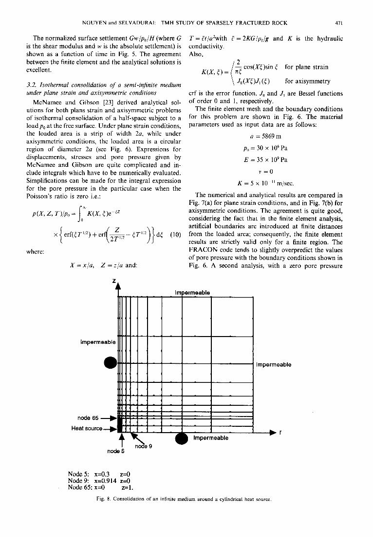
Node 5: x=0.3 z=o Node 9: x=0.914 z=O Node 65: x=0 z=l.
Fig. 8. Consolidation of an infinite medium around a cylindrical heat source.

412 NGUYEN and SELVADURAI: TMH STUDY OF SPARSELY FRACTURED ROCK
condition specified at the right hand side boundary, was performed with the FRACON code. That resulted in a slight underprediction of the results by the finite element method. For both plane strain and axisymmetric con- ditions, the Mandel-Cryer effect (i.e. the increase in pore pressure after the immediate increase and before the gradual decrease due to drainage) is manifested at all nodes being considered. The integration of equation (10) is performed numerically with the aid of the mathemati- cal manipulations code MATHEMATICA [26]. For the axisymmetric case, the numerical integration did not converge for node 9. Thus the results for that node are not shown in Fig. 7(b).
3.3. Consolidation of an injinite medium with an embedded cylindrical heat source
An analytical solution was provided by Booker and Savvidou [25] for the consolidation of an infinite homo- geneous saturated porous medium, with an embedded volumetric heat source V of constant heat output q(W/m3). The expressions for the temperature and pore pressure are, respectively:
5.OE-01
4.OE-01
3.OE-01
a
2.OE-01
l.OE-01
Node 5(FE)
Node 9(FE)
Node 65(FE)
Node S(analytical result)
Node 9(analytical result)
Node 65(analytical result)
Node S(analytica1 result)
Node 9(analytical result)
Node 65(analytical result)
Node 5(FE)
Node 9(FE)
Node 65(FE)
time Fig. 9. Cylindrical heat source-temperature and pore pressure evolution at different points.

NGUYEN and SELVADURAI: TMH STUDY OF SPARSELY FRACTURED ROCK 473
P(X, Y, z, t) = s x 4 1 - ~CC,/K &KR
where:
X = [/I,(1 -n> + n/If]@ + 2G) - (A + 2G/3)B’
R = [(x - x,)’ + (y - y,)’ + (z - z,)~]“~
xs, y,, z, are the coordinates of a point inside the volume V.
We consider here a cylindrical heat source. The same problem has been examined by Lewis and Schrefler [22] using the finite element code PLASCON, using an unspecified but presumably consistent system of units. For comparison purposes, we use here input data similar to those used by Lewis and Schrefler’s: radius of cylindrical source: 0.3, height of cylindrical source: 2, q = 1768.39, E =6000, v =0.4, K =0.4 x 10p5, u = 1.02857, pC =40, n =0.5, B =&=0.9 x 10⁻⁶, /?r= 0.63 x lo-‘.
The finite element mesh along with the boundary conditions for this problem are shown in Fig. 8. Axi- symmetric conditions are specified. The results for tem- perature and pore pressure at three different nodes are shown in Fig. 9. The FRACON results compare very well with the analytical solutions. It could be seen that at all points, the pore pressure increases due to thermal expansion of the pore fluid, and then gradually dissipates as the medium is allowed to consolidate.
3.4. Consolidation of an infinite medium with an embedded line heat source
We consider here a line source of 1 m length emitting heat at a rate of q = 40 W/m. The finite element mesh and the boundary conditions for this problem are shown in Fig. 10. Plane strain conditions are assumed. The line source runs through node 1 shown in Fig. 10. The following properties, typical of an artificial rock used in an experiment performed at Carleton University (cf. Section 4) were used in the analysis: n = 0.001, E = 27 GPa, v = 0.24, K = 1 x IO-l2 m/set, K = 0.563 J/m/s/C, pC = 2 x lo6 J/m’/“C, fi = & = 0.2 x lo-4”C-‘, pr= 0.4 x lo-3”C-1.
The temperature and pore pressure at nodes 3 and 9 are shown in Fig. 11. The finite element results are compared with the analytical solutions from Booker and Savvidou 1251. Considering that plane strain assump- tions are assumed to simulate a truly three-dimensional problem, the FRACON results are considered to be satisfactory and indicate trends which are consistent with the analytical results.
4. CALIBRATION WITH LABORATORY EXPERIMENT OF AN INTACT SYNTHETIC ROCK
An experiment was performed at Carleton University, Ottawa, Canada to investigate TMH coupling in intact rock. Cementious material was used to simulate hard rock. A cylinder, 50 cm in dia and 47 cm in height was cast with a special mixture of SIKA grout. Thermistors and pore pressure transducers are embedded in the
Impermeable, adiabatic
Node 3: x=0.014213 z=O Node 9: x=0.1 Z=O
Fig. 10. Consolidation around a line heat source.

474 NGUYEN and SELVADURAI: TMH STUDY OF SPARSELY FRACTURED ROCK
a) temperature
0 N&3@)
4 Nd9(FE)
Node 3(analytical result)
. . . . . . . Node 9(analytical result)
b) pore pressure
4.OE+OS
3.OE+OS
g 2.OE+OS a
1 .OE+OS
O.OE+OO
0 Node 3 (FE)
A Node 9 (FE)
Node 3(analytical solution)
--- Node 9(analytical solution)
the (s)
Fig. 11. Line heat source-temperature and pore pressure evolution.
cylinder. The cylinder was vacuum saturated after a 28-day curing period. The cylinder was then immersed in water and a heat source was applied at the surface. Temperatures and pore pressures were continuously recorded by a computerized data acquisition system during the experiment. The properties of the grout material were measured as follows: thermal heat conductivity: K = 0.563 J/m/sec/“C, heat capacity: pC = 2 x lo6 J/m3/“C, Poisson ratio: v = 0.24, Young’s modulus: E = 26.65 GPa, coefficient of volumetric ther-
mal expansion of the dry grout: 2 x 10-s/“C, hydraulic conductivity: 10-‘4-10-‘2 m/set.
Further details of the experimental procedures are given in [27]. The laboratory experiment was simulated with the FRACON code, using the above values as input data. The axisymmetric finite element mesh and the relevant boundary conditions are shown in Fig. 12. Since the hydraulic conductivity was very low, undrained conditions were assumed in the analysis. The calculated temperature values agree well with the experimental ones

NGUYEN and SELVADURAI: TMH STUDY OF SPARSELY FRACTURED ROCK 47.5
(Fig. 13). In order to match the calculated pore pressure with the experimental ones, the assumption of slightly imperfect saturation, has to be made. This assumption will result in a modified value of compressibility of the air/water mixture in the pores, as described below.
When the degree of saturation Sr is high (80% < Sr < 100%) one can neglect capillary and sur- face tension effects [28]. The porewater/air mixture could then be considered as a homogeneous single phase fluid, albeit with a higher compressibility than pure water. The relation between the compressibility of the equivalent single phase pore fluid and the degree of saturation could be derived as follows.
Consider a vacuum V of the porous medium, with a volume V, of voids. The void space is occupied partially with water and partially with air. By definition:
V,= V,Sr (13)
V, = V”(1 - Sr) (14)
where V, and V.. are, respectively, the water and air volumes.
When a pressure dp is applied to the water/air mix- ture, a volumetric compression in the voids dV, results, such that:
dV, dV, V=VSr +F(l -Sr).
” w a (15)
The compressibility of the air/water mixture is, by definition:
c,, = -A- dV, Vv dp
and from (15):
C,,=C,Sr+C,(l-Sr) (17)
where C,,, C,, C, are the compressibilities of, respect- ively, the air/water mixture, water and air.
Let us assume that the law of ideal gas is valid for air:
pabs If, = mRT (18)
where m is the number of moles, R is the universal gas constant, T is the absolute temperature (K) and pPbs is the absolute pressure:
Pabs = Palm + P (19)
where pat,,, is the atmospheric pressure and p is the relative pressure.
Differentiating equation (18) with respect to p, one obtains:
c,=ldV”_ Va dp
1 . Pabs
Defining compression as positive, and substituting the value of p&s from equation (19) into (20) we obtain:
1 c,=-. Patm + P
(21)
dT imposed 4 ) Y fly
Point 2 - Point 4 +
Point 5 -%++
Impermeible, adiabatic
Fig. 12. Heated cylinder-finite element mesh.
Equation (17) then becomes:
1 - Sr &,=C,Sr +----.
Patm + P (22)
In the governing equation (3) the bulk modulus of the pore fluid would be:
K,= l/C,, (23)
and would depend on the unknown p, making the equation nonlinear. A direct iteration method was incor- porated in the FRACON code to handle this nonlinear behaviour. We assumed that the degree of saturation of the cylindrical block varies from 94 to 99%, with a higher degree of saturation near the outer surface. With these modifications to the degree of saturation, a good match is obtained between the calculated and measured pore pressure values as shown in Fig. 13. Figure 14 shows that the absolute value of the pore pressure is sensitive to Sr, while the time transient is not much affected.
5. SIMULATION OF ROCK MASS RESPONSE TO A NUCLEAR FUEL WASTE REPOSITORY
The FRACON code was used in a preliminary analy- sis of the performance of a hypothetical repository situated at a depth of 1OOOm in a typical pluton of the Canadian Shield. The repository occupies an area of 2000 by 2000 m. It generates heat at an initial rate of 10.4 W/m’. Due to the decay in radioactivity of the

476 NGUYEN and SELVADURAI: TMH STUDY OF SPARSELY FRACTURED ROCK
3 .OE+O5-
2 .OE+O5
8 a
1 .OE+O5
O.OE+OO
time (min)
T2-exp
T4-exp
TS-exp
T2-PE
T4-FE
TS-FE
A p2 - S&8.9%
p2 - experimental
0 p4&=97.5%
_ -.---.---_. ___.____ @+xperimental
0 p5&=94%
_----_ -_-- p$experimental
Fig. 13. Heated cylinder-temperature and pore pressure evolution.
wastes, this heat production rate decays to 95% after 1 yr, 80% after 1000 yr and less than 10% after 10,000 yr. It is assumed that two vertical fracture zones, 20 m thick, exists at 100 m from two opposite edges of the repository. Assuming plane strain conditions, the rock mass response was simulated with the FRACON code. The finite element mesh is shown in Fig. 15, along with the boundary conditions. Due to symmetry, only half of the repository was considered. The following thermal-mechanical-hydrological properties of the rock mass are typically applicable to the Canadian Shield [l], and are used in the analysis: Young’s modulus and Poisson’s ratio: E = 35 GPa, v = 0.2, porosity n = 0.005, k = 3 W/m/C, C = 900 J/kg”C, density of
solids and fluid: ps = 2700 kg/m’, pr = 1000 kg/m’, coefficient of thermal expansion of solid and fluid: j?, = 0.24 x 10p4, br= 0.4 x lo-‘, hydraulic conduc- tivity: K = 1 x lo-” m/set.
The fracture zone is assumed to have axial and transverse hydraulic conductivities which are three orders of magnitude higher than those applicable to the competent rock mass. Its shear stiffness is assumed to be: D,,,, = 0.035 GPa (i.e. three orders of magnitude lower than the Young’s modulus of the competent rock mass). Its normal stiffness is assumed to be: Dyzy, = 3.5 GPa (i.e. one order of magnitude lower than the Young’s modulus of the competent rock mass). The thermal conductivity of the fracture zone in both axial and transverse direc-

NGUYEN and SELVADURAI: TMH STUDY OF SPARSELY FRACTURED ROCK 417
2.OE+OS
1 SE+05
‘;;i 6 1 .OE+05 CL
5 .OE+04
O.OE+OC
Pore Pressure at Point 4
* 8 m z
d
Time(min)
c3 p4-Sr=99%
0 p4-Sr=98.5%
0 p4-Sr=97.5%
- p4-experimental
Fig. 14. Heated cylinder--effect of degree of saturation on pore pressure.
tions are assumed to be equal to the one of the rock mass.
The temperature and the pore pressure increases at the center of the repository are shown in Fig. 16. The temperature increase shows two peaks, 50°C at 70 yr and 55°C at 5000 yr; this is consistent with results of others [I]. The pore pressure increase shows a peak of approx. 2.5 MPa at 40 yr. This pore pressure increase is due to the fact that the thermal expansion coefficient of the water is higher than the one of the solid matrix. Due to the low permeability of the medium, drainage is slow and the pore water expansion is impeded, resulting in pore pressure increases in early times. At later times, drainage of water away from the heat source gradually takes place resulting in pore pressure dissipation. Typical contours of pore pressure increases are shown in Fig. 17 (at 40 yr). These gradients can attain values of up to 100% (i.e. several orders of magnitude higher than typical regional
Fracture zone
Fig. 15. Finite element mesh for waste repository.
gradients in the Canadian Shield which are in the order of 0.1 “A) resulting in increased groundwater velocities diverging from the repository. Thus, the existing ground- water regimes will be significantly modified by the thermal pulse. One can also see that the fracture zone acts as a drainage feature and would constitute a prefer- ential pathway for groundwater exit to the surface area above the repository. Another implication of these high pore pressures is that effective stresses will be reduced, possibly resulting in a reduction of the strength of both the competent rock mass and the fracture zones.
A typical deformed configuration of the rock mass is shown in Fig. 18. Figure 18 shows that shear movements are induced in the fracture zone, an uplift of the ground surface is induced above the repository and thermal expansion of the rock matrix takes place around the repository. These displacements are only of the order of
10 100 1000 10000
time (yr)
Fig. 16. Pore pressure and temperature at centre of repository.

418 NGUYEN and SELVADURAI: TMH STUDY OF SPARSELY FRACTURED ROCK
2 to 2.5 1.5 to 2 1 to 1.5 0.5 to 1 MPa Fig. 17. Typical pore pressure contours at 40 yr after disposal.
centimetres, but they indicate significant disturbances in the stress regime and the structural integrity of the rock mass in the vicinity of the repository. Efforts will be devoted by the authors in the near future to further quantify the above hydrological and mechanical pertur- bations and their implications on the safety of the repository.
6. CONCLUSION
This paper described the current progress of the AECB’s research programme on TMH coupling in sparsely fractured rocks and its implications on Nuclear Fuel waste disposal. As part of this program, a computer code FRACON was developed, tested against analytical solutions, calibrated against a laboratory experiment, and used in the preliminary assessment of the TMH response of a rock mass around a repository. To gain more confidence in the validity of the conceptual model integrated in the FRACON code, laboratory exper- iments of TMH processes on intact and fractured granitic blocks are in progress at McGill University
??** Deformation scale is highly exaggerated Fig. 18. Deformed mesh.
for calibration/validation purposes. The code is also being currently used to simulate some test cases of DECOVALEX. A detailed analysis to quantify the implications of THM coupling on the safety of a NFW repository will also be performed in the near future.
Acknowledgements-The authors sincerely thank the Atomic Energy Control Board for its financial support, our colleagues at the AECB (D. Bottomley, K. Bragg, P. Flavelle, S. Lei, D. Metcalfe, V. Poliscuk, R. Stenson and J. Wallach) for reviewing this paper, and the labora- tory personnel (K. K. Kouloufakos, P. Carnaffan and R. Weidelich) at Carleton University for performing the heated block experiment.
Accepted for publication I February 1995.
REFERENCES
1. Atomic Energy of Canada Ltd. Used fuel disposal centre-a reference concept. Report TRM-3, AECL Whiteshell, Pinawa, Manitoba, Canada (1992).
2. Nguyen T. S. Canadian concept of nuclear fuel waste disposal- effectiveness of container, buffer and host rock as contaminant barriers. Proceedings of the 1992 Canadian Geotechnical Confer- ence, Paper 91 (1992).”
3. Cook N. G. W. Coupled processes in geomechanics. In Coupled Processes Associated with Nuclear Waste Repositories (Edited by Tsang C. F.), pp. 3946. Academic Press, New York (1987).
4. Chan T., Reid J. A. K. and Guvanasen V. Numerical modelling of coupled fluid, heat, and solute transport in deformable fractured rock. In Coupled Processes Associated with Nuclear Waste Reposi- tories (Edited by Tsang C. F.), pp. 605626. Academic Press, New York (1987).
5. Norrishad J. and Tsang C. F. Simulation of coupled thermal- hydraulic-mechanical interactions in fluid injection into fractured rocks. In Coupled Processes Associated with Nuclear Waste Reposi- tories (Edited by Tsang C. F.), pp. 6733678. Academic Press, New York (1987).
6. Onishi Y., Shibata H. and Kobayashi A. Development of finite element code for the analysis of coupled thermo-hydro-mechanical behaviors of a saturated-unsaturated medium. In Coupled Pro- cesses Associated with Nuclear Waste Repositories (Edited by Tsang C. F.), pp. 679698. Academic Press, New York (1987).
7. Witherspoon P. A. The need for field research in coupled processes. In Coupled Processes Associated with Nuclear Waste Repositories (Edited by Tsang C. F.), pp. 775-780. Academic Press, New York (1987).
8. SKI (Swedish Nuclear Power Inspectorate). DECOVALEX- Mathematical models of coupled THM processes for nuclear waste repositories. Report of Phase 1. Report SKI TR 93:41, Stockholm, Sweden (1993).
10.
11.
12. 13.
14.
9. Terzaghi K. Die Berechnung der Durchlassigkeitsziffer des Tones aus dem Verlauf der hydrodynamischen Spannungsers- cheinungen’. Ak. der Wissenschaften in Wien, Sitzungsberichte mathematisch-naturwissenschaftliche Klasse, Part lla, 132,12538, (1923). Biot M. A. General theory in three dimensional consolidation. J. Appl. Phys. 12, 155-164 (1941). Selvadurai A. P. S. and Nguyen T. S. Finite element modelling of consolidation of fractured porous media. Proceedings of the 1993 Canadian Geotechnical Conference, pp. 79-88 (1993). Freeze R. A. and Cherry J. A. Groundwater. Prentice-Hall (1979). Huyakom P. S. and Pinder G. F. Computational Methoa?s in Subsurface Flow. Academic Press, New York (1983). Rice J. R. and Cleary M. P. Some basic stress diffusion solutions for fluid-saturated elastic porous media with compressible con- stituents. Rev. Geophys. Space Phys. 14, 221-241 (1976). Zienkiewicz 0. C., Hympheson C. and Lewis R. W. A unified approach to soil mechanics problems (including plasticity and viscoplasticity). In Finite Element in Geomechanics (Edited by Gudehus G.), pp. 151-178. Wiley, New York (1977). Smith I. M. and Griffiths D. V. Programming the Finite Element Method. Wiley, New York (1988). Goodman R. E.. Tavlor R. L. and Brekke T. L. A model for the mechanics of jointed-rock. J. Soil Mech. Fdn Div. Proc. ASCE 94, 637659 (1968). Zienkiewicz 0. C., Best B., Dullage C. and Stagg K. Analysis of non-linear problems in rock mechanics with particular reference to
15.
16.
17.
18.

19.
20.
21.
22.
jointed rock systems. Proc. ad Congr. I~I. Sot. Rock Mech., Belgrade, Yugoslavia, 3, 501-509 (1970). Noorishad J., Witherspoon P. A. and Brekke T. L. A method for 24. coupled stress and flow analysis of fractured rock masses. Geo- technical Engineering Publication No. 716, Univ. of California, Berkeley (1971). 25. Ghaboussi J., Wilson E. L. and Isenberg J. Finite elements for rock joints and interfaces. J. Soil Mech. Fdn Div. Proc. ASCE 99, 833-848 (1973). 26. Desai C. S. and Nagaraj B. K. Constitutive modelling for inter- faces under cyclic loading. In Mechanics of Material Interfaces 27. (Edited by Selvadurai A. P. S. and Voyiadjis G. Z.), Vol. II, pp. 97-108. Elsevier, Amsterdam (1986). Lewis R. W. and Schrefler B. A. TheJinite element method in the 28. deformation and consolidation of porous media. Wiley, New York (1987).
23. McNamee J. and Gibson R. E. Plane strain and axially symmetric
NGUYEN and SELVADURAI: TMH STUDY OF SPARSELY FRACTURED ROCK 479
problems of the consolidation of a semi-infinite clay stratum. Q. J. Mech. Applied Math. XIII, Pt 2 (1960). Selvadurai A. P. S. and Yue Z. Q. On the indentation of a poroelastic layer. InI. J. Numerical Analytical Meth. Geomech. 18, 161-175 (1994). Booker J. R. and Savvidou C. Consolidation around a point heat source. Int. J. Numerical Analytical Meth. Geomech. 9, 173-184 (1985). Wolfram Research Inc. MATHEMATICA, version 2.2, Champaign, Ill., U.S.A. (1993). Selvadurai A. P. S. Experimental modelhng of thermal consoh- dation around a high level waste repository. AECB INFO dot., Atomic Energy Control Board, Ottawa, Canada. In Press. Vaziri H., Christian H. A. and Pitman T. Generalized form of Terzaghi’s consolidation solution. Proceedings of the 1992 Canadian Geotechnical Conference, Paper 65 (1992).