coupled thm problems in geotechnical engineering using ... · 4rd gid conference, ibiza, 2008 1...
TRANSCRIPT

4rd GiD Conference, Ibiza, 2008
1
Coupled THM problems in geotechnical engineering using CODE_BRIGHT-GiD
Sebastià Olivella, Jean Vaunat, Benoit Garitte and Nuria M. Pinyol
Department of Geotechnical Engineering and Geosciences, ETSECCPB, UPC
Abstract CODE_BRIGHT is a finite element program that solves coupled THM problems in geological materials. There are a number of questions involved when a module has to be developed to use it as a problem-type in GiD. The variety of constitutive laws that can be used in such a program and the variety of boundary and initial conditions require a development of pre-process and post-process with a sufficient degree of generality. The paper shows examples of applications that cover different types of geotechnical and environmental engineering problems. 1. INTRODUCTION The program CODE_BRIGHT solves the coupled THM problems in geological materials using the finite element method. Customization to use GiD as pre- and post-process of CODE_BRIGHT was performed and this permits to tackle a number of problems in the field of geotechnical and environmental engineering. The program CODE_BRIGHT couples the thermal (multiphase heat transport in porous media), hydraulic (two phase flow of liquid and gas in porous media including vapour), mechanical (unsaturated soil mechanics under isothermal conditions) problems and the solute transport. These problems require a number of constitutive laws and these have been organized accordingly in the interface. Since the number of material properties and parameters is large, it is useful to import sets of parameters if they are similar in other applications, so this is a convenient utility in GiD.
A number of improvements have been done in the code since its early development (Olivella et al 1996). One of them is the construction/excavation which is handled by activating and deactivating sub domains. For construction, an intermediate state is considered during which the weight of the layer under construction is applied linearly. While construction permits the described smooth process, excavation is more complicated as removing a layer causes changes of variables (stresses, pressures) in the remaining material which are fast and strongly coupled.
The examples shown in this paper are in 2D and 3D. The highly nonlinear coupled problems handled by the program are sometimes the limiting factor as the number of time steps to be solved is very large (for instance: small time steps during heating periods, after excavation, after fluid injection or pressure changes). So, one has to think in the space and time dimensions.

4rd GiD Conference, Ibiza, 2008
2
2. GENERAL DESCRIPTION OF CODE_BRIGHT
A porous medium composed by solid grains, water and gas is considered. Thermal, Hydraulic and Mechanical aspects are taken into account, including coupling between them in all possible directions. As illustrated in Figure 1, the problem is formulated in a multiphase and multispecies approach.
Gas phase: dry air +
water vapour
Solid phase
Liquid phase: water + dissolved air
The three phases are: • solid phase (s): • liquid phase (l): water + air
dissolved + solute • gas phase (g): mixture of dry
air and water vapour The three species are:
• solid (-): mineral • water (w): as liquid or
evaporated in the gas phase • air (a): dry air, as gas or
dissolved in the liquid phase • solute (c): in the liquid phase
Figure 1. Schematic representation of an unsaturated porous material
Figure 2. a) Customized window where the equations to be solved are selected. Solution strategy and Output sections contain default values (e.g. for tolerances that
control convergence of nonlinear iterations). b) Customized window for material parameter input. ITYCL is used to decide types of laws inside a constitutive law (e.g.
Viscoplasticity for granular materials may have different options of flow rules).
The program CODE_BRIGHT solves the following equations:
Equation: mechanical equilibrium equations (1, 2 or 3 dimensions):
∇ ⋅ + =b 0σσσσ Unknown: displace-ments, u=(ux,uy,uz)
Equation: water mass balance:
( ) ( )w w w w wl l l g g g l gS S f
t
∂ ρ ω φ + ρ ω φ + ∇ ⋅ + =∂
j j Unknown: liquid pressure, Pl (MPa)

4rd GiD Conference, Ibiza, 2008
3
Equation: air mass balance:
( ) ( )a a a a al l l g g g l gS S f
t
∂ ρ ω φ + ρ ω φ + ∇ ⋅ + =∂
j j Unknown: gas pressure, Pg (MPa)
Equation: internal energy balance:
( )( )1 ( ) Qs s l l l g g g c Es El EgE E S E S f
t
∂ ρ − φ + ρ φ + ρ φ + ∇ ⋅ + + + =∂
i j j j Unknown:
temperature, T (oC)
Equation: solid mass balance:
( )( )1 ( ) 0s st
∂ ρ − φ + ∇ ⋅ =∂
j Unknown: porosity, φ(-)
Equation: solute mass balance:
( ) ( )s s sl l l lS f
t
∂ ρ ω φ + ∇ ⋅ =∂
j Unknown: solute concentration, slω (-)
The resulting system of PDE's (Partial Differential Equations) is solved numerically. The numerical approach can be viewed as divided into two parts: spatial and temporal discretizations. Finite element method is used for the spatial discretization while finite differences are used for the temporal discretization. The discretization in time is linear and the implicit scheme uses two intermediate points, tk+ε (for nonlinear terms) and tk+θ (for gradient terms) between the initial tk and final tk+1 times. Finally, since the problems are non-linear, the Newton-Raphson method was adopted to find an iterative scheme.
Figure 3. a) Customized window for layer/material construction. b) Customized window for hydraulic boundary condition application. For 2D problems the
condition can be applied to node/line/surface. Parameter list contains several items as the thermo hydraulic boundary condition equations are complex
(evaporation/radiation/rain/…) Figure 2 and 3 show the aspect of the interface with different windows customized and incorporated in GiD. Figure 2a shows the Problem data window. The equations to be solved are chosen here. There is no restriction on the combination of equations to be solved. The number of degrees of freedom ranges from one to seven depending on the dimensions and equations chosen. Figure 2b shows the customized Materials window. Once in the window the mechanical, hydraulic and thermal, the phase properties and the

4rd GiD Conference, Ibiza, 2008
4
construction/excavation sections are displayed. This part is continuously growing and changing as research activity in this field requires new modifications. Figure 3a shows the construction of a given layer at the time interval number 6 (the layer is inactive during the preceding 5 intervals i.e. with a value of -1). The time intervals in CODE_BRIGHT are sequential time periods defined by an initial time a final time and a given time discretization parameters (initial time step and upper bound time step). Finally, figure 3b shows the customized window for the hydraulic and thermal boundary conditions (Conditions). These are intimately related with the construction/excavation as some contours which are exposed to atmosphere at some time intervals become internal in some others. Hydraulic and thermal boundary conditions are defined in a comprehensive way to account for evaporation, heat radiation, convection, infiltration, constant pressure and constant temperature.
3. APPLICATION OF CODE_BRIGHT TO GEOTECHNICAL ENGIN EERING PROBLEMS.
In this section some examples that have been solved with CODE_BRIGHT are briefly described. These examples are related to different research activities at the Department of Geotechnical Engineering and Geosciences (UPC).
Figure 4 refers to an analysis of an experiment simulating radioactive waste disposal in an unsaturated rock. Heating up to 200 oC implies water evaporation around the drift and this manages to dry the rock. The different properties of the rock matrix and the rock fractures produce different desaturation of the pores and consequently different permeability. The heating also produces volumetric (compressive and dilatative) and shear deformation in the rock. These deformations induce changes in the intrinsic permeability. Both hydraulic and mechanical processes induce changes in permeability. This affects the flow of water and gas which in turn influences the heat transport and the temperature (Olivella and Gens, 2005).
Figure 5 shows a series of calculations related to behaviour of a 50 m high earth dam. These geotechnical structures should be analyzed using coupled hydro-mechanical equations. There are aspects related to unsaturated soils (unsaturated flow and collapse deformations) which are not considered in engineering practice. Figure 5 shows the pressure distribution in the natural ground and the clay core after construction. Construction is a process which should be necessarily modeled in order to obtain in a realistic way the water content, the stresses and the density of the materials. Deformability and strength are a function of these variables. Pore water pressure distribution and displacements at the end of the impoundment are also indicated in the figure.
Rapid drawdown may induce failure of earth dams due to high pore pressures in the upstream shoulder (Figure 6). However, pore pressure calculation requires the solution of a coupled problem as both pore pressure and stresses change on the upstream earth dam boundary. In some classical methods, the pore pressure is determined considering only the flow problem but this implies an overestimation of pressures which is not realistic (Alonso and Pinyol, 2008; Pinyol et al, 2008).

4rd GiD Conference, Ibiza, 2008
5
Figure 7 is another example related to radioactive waste disposal. Gas generated in wastes may migrate by diffusion and advection. In the case of two phase flow, the pore pressure generated may be high enough to induce discontinuity opening. This produces permeability variations which can only be properly determined by solving coupled hydro-mechanical problem. Figure 7 shows an experiment of gas migration in a scheme that contains a barrier made of sand-bentonite. The complex protocol of construction / water pressurization / gas injection requires several steps of modeling. For this type of problems the restart option is very convenient, otherwise the complete simulation of the problem requires long term calculations as time steps are relatively small (time step is controlled by the worse equation in terms of error). See more details in Olivella and Alonso (2004).
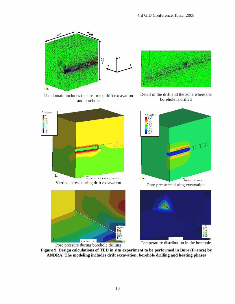
Simulation of coupled problems is also carried out at the level of laboratory experiments. Figure 8 shows the modelling of gas injection in a soil (initially saturated) with permeability variations induced by changes in degree of saturation (water content) and deformations. In this case the Experimental set up and laboratory investigations have been performed by Harrington and Horseman (2003). Similar tests are currently performed in the Geotechnical Laboratory of the UPC. Figure 9 shows the analyses that are currently performed (Garitte et al, 2008) as desing calculations for the future TED experiment. The experiment will be launched after the excavation of the GED gallery (foreseen in October-November 2008), an extension of an existing GMR gallery. The excavation of a small niche is planned in the GED drift, from which the heater boreholes and the instrumentation boreholes will be drilled. One of the objectives of the design work is also the determination of the optimal instrumentation pattern.
4. CONCLUSIONS
This paper reviews a number of applications of CODE_BRIGHT-GiD. Although most of the problems are related to waste disposal, which in fact was the original field of work, problems related to civil engineering geotechnical problems appear and should also be considered and analyzed.
5. REFERENCES
Alonso E.E. & N. M. Pinyol (2008) Unsaturated Soil Mechanics in Earth and Rockfill Dam Engineering. First European Conference on Unsaturated Soils. Durham. United Kingdon. In print.
Garitte, B. Vaunat, J. and A. Gens (2008). Thermo-Hydro-Mechanical Design Calculations for the TED Experiment, Internal Report for ANDRA (France), Department of Geotechnical Engineering and Geosciences.
Harrington, J.F., and S.T. Horseman (2003) Gas Migration in KBS-3 Buffer Bentonite: Sensitivity of Test Parameters to Experimental Boundary Conditions, SKB Technical Report TR 03–02, 2003.
Olivella, S., A. Gens, J. Carrera & E. E. Alonso (1996) Numerical formulation for simulator (CODE_BRIGHT) for coupled analysis of saline media. Engineering computations, 13(7): 87-112.
Olivella, S. & E. E. Alonso (2004). Modelling the hydro-mechanical behaviour of GMT in situ test including interface elements, GMT Report. UPC-NAGRA.
Olivella, S. & A. Gens (2005). Double structure THM analysis of a heating test in a fractured tuff incorporating intrinsic permeability variations. Int. J. Numer. Anal. Met. Geomech. 42, 667–669.
Pinyol, N.M., E.E. Alonso & S. Olivella (2008) Rapid drawdown in slopes and embankments. Water resources research. In print.

4rd GiD Conference, Ibiza, 2008
6
Heating experiment
Idealization of the repository
Finite element mesh duplicated to represent the rock matrix and the fractures
Degree of saturation at the rock matrix and fracture after 4 years of heating up to 200 oC
Figure 4. Modelling THM response of a fractured rock (Yucca Mountain, Nevada) using a doble structure approach. A total of 5 dof/node are solved in a monolithic way (u, pl, pg, T).

4rd GiD Conference, Ibiza, 2008
7
Pore pressure distribution after construction (only positive)
Water pressure (only positive) and deformed mesh after reservoir impoundment
Figure 5. Modelling earth dams. Construction generates pore pressure, stress increments and accumulated plastic strains.
Concret core wall
Morainic fill
Rock fill
Water pressure after rapid drawdown (only positive)
300
400
500
600
700
800
0 400 800 1200 1600 2000Time (days)
Wat
er P
ress
ure
(kP
a)
Coupled Mod. Uncoupled Mod.
Drawdown completed
Start drawdown
Pore pressure evolution for coupled and uncoupled analyses
Figure 6. Modelling rapid drawdown in earth dams.

4rd GiD Conference, Ibiza, 2008
8
Gas pressure
Irreversible deformations
Underground radioactive waste
repository
Interface contact with rock
1.E-18
1.E-17
1.E-16
1.E-15
1.E-14
1.E-13
1.E-12
1.E-11
1.E-10
1.E-09
1.E-08
820
910
1000
1090
1180
1270
1360
1450
1540
1630
1720
1810
1900
1990
2080
2170
2260
Time (days)
Intr
insi
c pe
rmea
bilit
y (m
2) .
327 369 370
378 394 569RGI1 RGI2
RGI3CAVERN PRESSURIZATION
RGI4
K v is plotted
Permeability evolution
0
100
200
300
400
500
600
700
800
1-s
ep-0
0
30-n
ov-0
0
28-f
eb-0
1
29-m
ay-0
1
27-a
go-0
1
25-n
ov-0
1
23-f
eb-0
2
24-m
ay-0
2
22-a
go-0
2
20-n
ov-0
2
18-f
eb-0
3
19-m
ay-0
3
17-a
go-0
3
15-n
ov-0
3
13-f
eb-0
4
13-m
ay-0
4
11-a
go-0
4
Time (d)
Pre
ssur
e (M
Pa)
0
0.1
0.2
0.3
0.4
0.5
0.6
0.7
0.8PE/9/7/0
node 457 Layer 9 (Pliq)
node 457 Layer 9 (Pgas)
RGI1 RGI2
RGI3
CAVERN PRESSURIZATION RGI4
Pressure evolution
Figure 7. Modelling gas generation (due to waste degradation) and flow through geological materials

4rd GiD Conference, Ibiza, 2008
9
Injection assembly
Cap screw
Stainless steel filters
End closure
Axial stress sensor
Pressure vesselRadial sink arrays
Push-rod
Viton ‘O’ ring
Annular tube
Bentonite
Radial stress sensor
Remote porewater pressure sensor
Experimental set up to investigate gas migration
in cylindrical samples
Gas fluxes induced by gas injection
in the centre of the sample. Sinks are located on the external surface.
Degree of saturation in the
sample
Gas pressure induced by gas
injection
0.E+00
1.E-08
2.E-08
3.E-08
4.E-08
5.E-08
0 1000 2000 3000 4000 5000 6000
Time (h)
Gas
flow
rat
e (k
g/s)
Injected gasSinkCentral sinkSink
Figure 8. Gas flow is simulated using a coupled formulation to account for permeability variations induced by deformations (Experiments from Harrington
and Horseman, 2003)
4rd GiD Conference, Ibiza, 2008
10
The domain includes the host rock, drift excavation
and borehole
Detail of the drift and the zone where the borehole is drilled
Vertical stress during drift excavation
Pore pressures during excavation
Pore pressure during borehole drilling
Temperature distribution in the borehole
Figure 9. Design calculations of TED in situ experiment to be performed in Bure (France) by ANDRA. The modeling includes drift excavation, borehole drilling and heating phases