coupler operation manual · manual and signs (decals) on the equipment. follow warnings and...
TRANSCRIPT

www.geith.com PT No. 823000028858AReleased 03-2014
EN
COUPLER OPERATION MANUAL


Contact us:Ireland - Geith International
Grangegeeth, Slane, Co. Meath, IrelandT: +353 (0)41 982 4143 F: +353 (0)41 982 4478
UK - Geith International UK LtdUnit 6, Hoel - Y - Gamlas, Parc Nantgarw, Nantgarw, Cardiff, CF15 7QU, UK
T: +44 (0)1443 845 666 F: +44 (0)1443 844 [email protected]
US - Geith Inc2905 Shawnee Industrial Way, Shawnee, GA 30024T: +1 866 472 4373 (Toll Free) F: +1 866 472 4950
France - Agent Commercial France de Geith International Ltd203 route de Grenoble, 69800 Saint Priest, France
No Vert: 0800916626 F: +33 (0)4 72 79 32 [email protected]
www.geith.com

ContentsIntroduction
TO THE CUSTOMER . . . . . . . . . . . . . . . . . . . . . . . . . . . . . . . . . . . . . . . . . . . . . . . .3
Safety
SAFETY INSTRUCTIONS . . . . . . . . . . . . . . . . . . . . . . . . . . . . . . . . . . . . . . . . . . . .5
Operation
OPERATING INSTRUCTIONS . . . . . . . . . . . . . . . . . . . . . . . . . . . . . . . . . . . . . . . .13Engaging Attachments . . . . . . . . . . . . . . . . . . . . . . . . . . . . . . . . . . . . . . . . . . .13Releasing Attachments . . . . . . . . . . . . . . . . . . . . . . . . . . . . . . . . . . . . . . . . . . .15Releasing Attachment Using The Pressure Signal Bypass . . . . . . . . . . . . . . . .16
Servicing
SAFETY INSTRUCTIONS . . . . . . . . . . . . . . . . . . . . . . . . . . . . . . . . . . . . . . . . . . .21QUICK COUPLER COMPONENT IDENTIFICATION (HYDRAULIC). . . . . . . . . . . . .22QUICK COUPLER COMPONENT IDENTIFICATION (MECHANICAL) . . . . . . . . . . .23QUICK COUPLER INSPECTION . . . . . . . . . . . . . . . . . . . . . . . . . . . . . . . . . . . . . .26TROUBLESHOOTING . . . . . . . . . . . . . . . . . . . . . . . . . . . . . . . . . . . . . . . . . . . . . .24
After Installation / Operation . . . . . . . . . . . . . . . . . . . . . . . . . . . . . . . . . . . . . . .26Daily Inspection . . . . . . . . . . . . . . . . . . . . . . . . . . . . . . . . . . . . . . . . . . . . . . . .26Weekly Inspection. . . . . . . . . . . . . . . . . . . . . . . . . . . . . . . . . . . . . . . . . . . . . . .26Electrical System . . . . . . . . . . . . . . . . . . . . . . . . . . . . . . . . . . . . . . . . . . . . . . .24Hydraulic System . . . . . . . . . . . . . . . . . . . . . . . . . . . . . . . . . . . . . . . . . . . . . . .24Mechanical System. . . . . . . . . . . . . . . . . . . . . . . . . . . . . . . . . . . . . . . . . . . . . .25
PART REPLACEMENT. . . . . . . . . . . . . . . . . . . . . . . . . . . . . . . . . . . . . . . . . . . . . .27Required Tools . . . . . . . . . . . . . . . . . . . . . . . . . . . . . . . . . . . . . . . . . . . . . . . . .27Removing The Quick Coupler . . . . . . . . . . . . . . . . . . . . . . . . . . . . . . . . . . . . . .27Disassembly (QC60 - QC140) . . . . . . . . . . . . . . . . . . . . . . . . . . . . . . . . . . . . . .28Disassembly (QC35 - QC55) . . . . . . . . . . . . . . . . . . . . . . . . . . . . . . . . . . . . . . .28Disassembly (Mechanical Coupler QC45 - QC90) . . . . . . . . . . . . . . . . . . . . . . .29
Specifications
SPECIFICATIONS . . . . . . . . . . . . . . . . . . . . . . . . . . . . . . . . . . . . . . . . . . . . . . . . .33
Warranty
WARRANTY PROGRAM . . . . . . . . . . . . . . . . . . . . . . . . . . . . . . . . . . . . . . . . . . . .35
www.geith.com 1

Visit us on www.Geith.com and learn more about operations, servicing and
installation on our Geith.TV menu.
2 www.geith.com

INTRODUCTION
TO THE CUSTOMERThank you for purchasing a Geith Quick Coupler. Geith attachments are designedand manufactured to the highest quality standards and backed up by the Geithcommitment to service and parts support. Learn more at www.geith.com
Instructions are necessary before operating or servicing the equipment.All personnel must read and understand the Operation Manual and signs(decals) on the equipment. Follow warnings and instructions in themanual when making adjustments, repairs or servicing. Check for correctfunction after making adjustments, repairs or servicing. Failure to followinstructions can cause injury or death.
IDENTIFICATION
REARSAFETY LOCK
INFORMATION PLATE
LIFTING EYE
FRONT SAFETY LOCK
FIXED HOOK
www.geith.com 3

INTRODUCTION
APPLICATION RECOMMENDATIONSThe Geith range of quick couplers are designed for use with all makes ofexcavators, combined with a wide range of attachments, to suit a wide range ofwork applications.
It is the responsibility of the owner and operators of the quick coupler to ensurethat the quick coupler is used and maintained in a safe and appropriate mannerthat will not cause damage to or make unsafe in any way, the operation of thequick coupler or equipment being used.
4 www.geith.com

SAFETY
SAFETY INSTRUCTIONSThis symbol is used to call attention toinstructions concerning personalsafety. Be sure to observe and followthese instructions.
The signal word DANGER on theequipment and in the manualidentifies a hazardous situation which,if not avoided, WILL result in death orserious injury.
The signal word WARNING on themachine and in the manual indicates apotentially hazardous situation which,if not avoided, COULD result in deathor serious injury.
The signal word CAUTION on themachine and in the manual indicates apotentially hazardous situation which,if not avoided, MAY result in minor ormoderate injury. It may also be used toalert against unsafe practices.
This notice identifies procedureswhich must be followed to avoiddamage to the machine.
Instructions are necessary beforeoperating or servicing theequipment. All personnel must readand understand the OperationManual and signs (decals) on theequipment. Follow warnings andinstructions in the manual whenmaking adjustments, repairs orservicing. Check for correctfunction after making adjustments,repairs or servicing. Failure tofollow instructions can cause injuryor death.
www.geith.com 5

SAFETY
Operating SafetyAVOID SERIOUS INJURY OR DEATH
Failure to fully engage front and rearsafety locks before operating canallow the attachment to come off.
• All users / operators must beproperly trained in the use of thespecific model of quick couplerintending to be used.
• It is the responsibility of themachine owner to ensure onlyproperly trained operators use thequick coupler.
• Failure to operate and maintainequipment correctly can result inserious injury or death.
• Do not allow bystanders orpersonnel in maximum reach andswing area while operatingequipment.
• Never move a load abovepersonnel.
• Never allow riders on quickcoupler or attachments.
Servicing Safety
• Always place the quick couplerand attachment on a flat, levelsurface before servicing.
• Stop engine and remove machinekey.
• Always depressurise hydraulicsystem before servicing.
• Collect and retain all oil releasedfrom system during manitenance.
6 www.geith.com
SAFETY
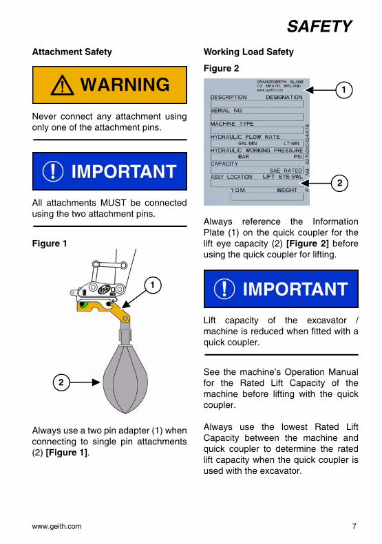
Attachment SafetyNever connect any attachment usingonly one of the attachment pins.
All attachments MUST be connectedusing the two attachment pins.
Figure 1
Always use a two pin adapter (1) whenconnecting to single pin attachments(2) [Figure 1].
Working Load Safety
Figure 2
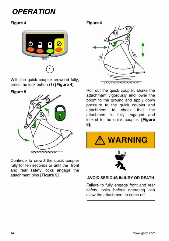
Always reference the InformationPlate (1) on the quick coupler for thelift eye capacity (2) [Figure 2] beforeusing the quick coupler for lifting.
Lift capacity of the excavator /machine is reduced when fitted with aquick coupler.
See the machine’s Operation Manualfor the Rated Lift Capacity of themachine before lifting with the quickcoupler.
Always use the lowest Rated LiftCapacity between the machine andquick coupler to determine the ratedlift capacity when the quick coupler isused with the excavator.
1
2
1
2
www.geith.com 7

SAFETY
Quick Coupler Lifting SafetyTIPPING CAN CAUSE SERIOUS INJURY OR DEATH
Do not exceed the machine’s RatedLift Capacity.
Only use the quick coupler lift eye forlifting if the machine it is installed on israted and equipped for liftingoperations.
Before using the quick coupler lift eye,remove attachment that is connectedto the quick coupler.
Use of an appropriate shackle isrecommended when using the quickcoupler for lifting.
Figure 3
Never use the attachment pinconnection hooks of the quick couplerfor lifting [Figure 3].
Figure 4
Always lift with the quick couplervertical, allowing the load and liftingaccessories to hang free withoutcontacting the coupler body [Figure4].
Failure to follow the suggested liftingprocedure may result in equipmentfailure and the loss of the supportedload.
8 www.geith.com

SAFETY
DECAL INSTALLATIONInstruction and warning decals aresupplied with this quick coupler.
Figure 5
Install the two decals inside of the cabwindow [Figure 5].
NOTE: Replace any damagedinstruction and warningdecals.
Operating Instructions decal (Item 1)[Figure 5].
Operating Instructions decal (Item 2)[Figure 5].
1
2
827000028754B
827000087399
www.geith.com 9

SAFETY
DECAL IDENTIFICATION827000087398
827000087399
10 www.geith.com

SAFETY
Figure 6Interference with machine, quickcoupler and attachment [Figure 6].
Operate the quick coupler andattachment through its full range ofmotion to check interference betweenattachment and machine that coulddamage machine, quick coupler andattachment [Figure 6].
NOTE: Replace any damagedinstruction and warningdecals.
Figure 7
Pinch Hazard [Figure 7].
WARNINGMOVING PARTS CAN CAUSE
SERIOUS INJURY
Keep hands and fingers away frommoving parts [Figure 7].
NOTE: Replace any damagedinstruction and warningdecals.
827000087399
827000087398
www.geith.com 11

SAFETY
12 www.geith.com

OPERATION
OPERATING INSTRUCTIONSEngaging Attachments
AVOID INJURY OR DEATH
Keep bystanders away whenengaging and releasing attachment.
Figure 1
Press power button (1) [Figure 1].
Press unlock button (2) [Figure 1]within six seconds of pressing powerbutton, curl to build the pressure toopen the front (3) and rear (4) safetylocks.
Figure 2
Lower the quick coupler and engagethe front pin (1) [Figure 2] of theattachment.
Figure 3
Always lift with the quick couplervertical, allowing the attachment linkpin to contact the coupler body[Figure 3].
1 2
3
4
1
www.geith.com 13
OPERATION
Figure 4With the quick coupler crowded fully,press the lock button (1) [Figure 4].
Figure 5
Continue to crowd the quick couplerfully for ten seconds or until the frontand rear safety locks engage theattachment pins [Figure 5].
Figure 6
Roll out the quick coupler, shake theattachment vigorously and lower theboom to the ground and apply downpressure to the quick coupler andattachment to check that theattachment is fully engaged andlocked to the quick coupler. [Figure6].
AVOID SERIOUS INJURY OR DEATH
Failure to fully engage front and rearsafety locks before operating canallow the attachment to come off.
1
14 www.geith.com

OPERATION
Releasing AttachmentsAVOID INJURY OR DEATH
Keep bystanders away whenengaging and releasing attachment.
Park the machine on flat, levelsurface.
Figure 7
Lower quick coupler and attachmentto the ground [Figure 7].
Figure 8
Fully crowd the quick coupler inward[Figure 8].
Figure 9
Press power button (1) [Figure 9].
Press unlock button (2) [Figure 9]within six seconds of pressing powerbutton.
Continue to crowd the quick coupleruntil the pressure signal LED (3)[Figure 9] illuminates.
Figure 10
Lower the attachment to the ground.
Move the quick coupler away from theattachment [Figure 10].
1 2
3
www.geith.com 15

OPERATION
Releasing Attachment Using The Pressure Signal BypassPRESSURE SIGNAL BYPASS
To open the coupler, the standardGeith control system requires theoperator to fully crowd the coupler toobtain a pressure signal. With largeattachments or specific attachments(such as pallet forks, ....) this may notbe possible. By following a differentopening sequence we can bypass thepressure signal and still maintain asafe opening procedure.
AVOID INJURY OR DEATH
Keep bystanders away whenengaging and releasing attachment.
Park the machine on flat, levelsurface.
Figure 11
Lower quick coupler and attachmentto the ground [Figure 11].
Figure 12
Press power button (1) [Figure 12].
Press unlock button (2) [Figure 12]within six seconds of pressing powerbutton.
1 2
16 www.geith.com

OPERATION
Figure 13Press and HOLD pressure bypass (1)[Figure 12] (six seconds) until thepressure signal illuminates.
With the safety locks released, movethe quick coupler away from theattachment.
NOTE: The locks will open at aslower rate. To speed up theopening rate, make smalladjustments to the bucketcurl lever (open andclosing).
1
6s
www.geith.com 17

OPERATION
MECHANICAL AUTO-LOCK QUICK COUPLEREngaging Attachments
Figure 14
With the Auto-Lock (1) open, Lowerthe quick coupler and engage the frontpin (2) [Figure 14] of the attachment.
Figure 15
Always lift with the quick couplervertical, allowing the attachment linkpin to contact the coupler body[Figure 15].
Figure 16
Install the drive bar (1) onto thecylinder drive shaft at the back of theengaging plate. While tightening, theAuto-Lock clasp (2) [Figure 16] willclose over the front pin securing theattachment to the Quick-Coupler.
Continue tightening until the engagingplate (3) [Figure 16] is under theattachment link pin.
Do not extend drive bar (by use ofextension tube etc.) over tighteningmay result in difficulty releasing theattachment, or damage to themechanism.
Remove the drive bar and store inexcavator cab.
2
1
1
2
3
18 www.geith.com

OPERATION
Figure 17Roll out the quick coupler, shake theattachment vigorously and lower theboom to the ground and apply downpressure to the quick coupler andattachment to check that theattachment is fully engaged andlocked to the quick coupler [Figure17].
AVOID SERIOUS INJURY OR DEATH
Failure to fully engage front and rearsafety locks before operating canallow the attachment to come off.
Releasing Attachments
AVOID INJURY OR DEATH
Keep bystanders away whenengaging and releasing attachment.
Park the machine on flat, levelsurface.
Figure 18
Install the drive bar (1) [Figure 18]onto the cylinder drive shaft at back ofengaging. Turn the drive bar anti-clockwise to release the back pin lock.
Continued loosening to open the Auto-Lock (2) [Figure 18].
Remove drive bar from the quickhitch.
1
2
www.geith.com 19
OPERATION
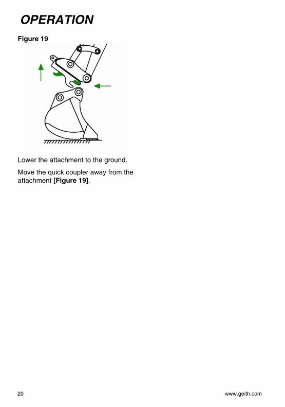
Figure 19Lower the attachment to the ground.
Move the quick coupler away from theattachment [Figure 19].
20 www.geith.com
SERVICING
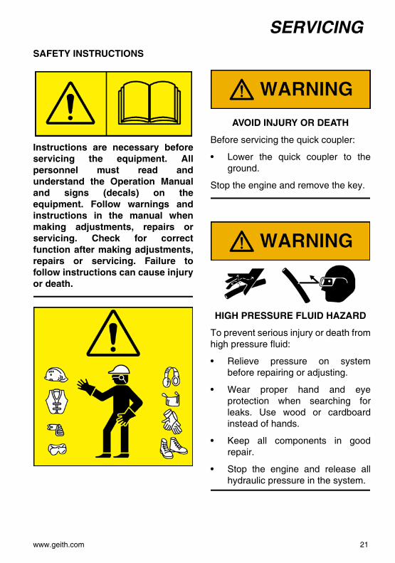
SAFETY INSTRUCTIONSInstructions are necessary beforeservicing the equipment. Allpersonnel must read andunderstand the Operation Manualand signs (decals) on theequipment. Follow warnings andinstructions in the manual whenmaking adjustments, repairs orservicing. Check for correctfunction after making adjustments,repairs or servicing. Failure tofollow instructions can cause injuryor death.
AVOID INJURY OR DEATH
Before servicing the quick coupler:
• Lower the quick coupler to theground.
Stop the engine and remove the key.
HIGH PRESSURE FLUID HAZARD
To prevent serious injury or death fromhigh pressure fluid:
• Relieve pressure on systembefore repairing or adjusting.
• Wear proper hand and eyeprotection when searching forleaks. Use wood or cardboardinstead of hands.
• Keep all components in goodrepair.
• Stop the engine and release allhydraulic pressure in the system.
www.geith.com 21

SERVICING
QUICK COUPLER COMPONENT IDENTIFICATION (HYDRAULIC)ITEM DESCRIPTION ITEM DESCRIPTION
1 CAST WEDGE 11 DIE-SPRING
2 GUIDE PIN SUB-ASSEMBLY 12 SLIDING BLOCK
3 CHECK VALVE 13 BUNG
4 LINK 14 HYDRAULIC CYLINDER
5 LOCK PIN 15 ROLL PIN
6 LOCK LINK PIN 16 ROLL PIN
7 DIE SPRING 17 SPLIT PIN
8 DIE SPRING BUSHING 18 NYLON LOCKNUT
9 BOLT, W / HOLE 19 SEAL KIT
10 CAST-LOCK
3
4
2
1
11
18 87
9
14
13
10
15
6
5
16
12
17
22 www.geith.com

SERVICING
QUICK COUPLER COMPONENT IDENTIFICATION (MECHANICAL)ITEM DESCRIPTION ITEM DESCRIPTION
1 MANUAL CYLINDER ASSEMBLY 15 EXTENSION BAR2 CAST WEDGE 16 GUARD3 POWER BAR 17 CAST-LOCK4 LINK 18 FRAME ASSEMBLY5 LOCK PIN 19 BUNG6 LOCK LINK PIN 20 CAP SCREW7 DIE SPRING 21 ROLL PIN8 DIE SPRING BUSHING 22 ROLL PIN9 BOLT, W / HOLE 23 ROLL PIN10 COMPRESSION SPRING 24 ROLL PIN11 FIXED LOCK BUSHING 25 SPLIT PIN12 LOCK NUT 26 GREASE NIPPLE13 MOVING LOCK BUSHING 27 LOCKNUT14 DEEP SOCKET 28 ROLL PIN
14
3 15
1220
16 22 13
11
10
24
28
9 1
19
4
17
18
521
6
2
23
26
25 27 87
www.geith.com 23

SERVICING
TROUBLESHOOTINGElectrical System
Hydraulic System
PROBLEM CAUSE CORRECTION
Control panel notworking.
Loose / faulty wires. Check wires.Faulty machine fuse. Replace machine fuse.Faulty ground wire. Check ground wire.Faulty control box. Replace control box.
PROBLEM CAUSE CORRECTION
Safety locks notreleasing.
Low hydraulic pressure. Check hydraulic pressure.Faulty pressure switch. Replace pressure switch.Faulty check valve. Clean or replace check
valve.Faulty cylinder. Replace cylinder.
Safety locks releasingduring operation.
Faulty seals in cylinder. Replace seals.Faulty check valve. Clean or replace check
valve.Faulty cylinder. Replace cylinder.
Safety locks closing whenchanging attachments.
Faulty check valve or pilotvalve.
Clean or replace checkvalve or pilot valve.
Faulty cylinder. Replace cylinder.
24 www.geith.com

SERVICING
Mechanical SystemPROBLEM CAUSE CORRECTION
Safety locks not engagingor releasing.
Faulty cylinder. Replace cylinder.Drive bar retaining collarloose or missing.
Tighten or replaceretaining collar.
Worn drive bar. Replace drive bar.Worn internal discsprings.
Replace internal discsprings.
www.geith.com 25
SERVICING
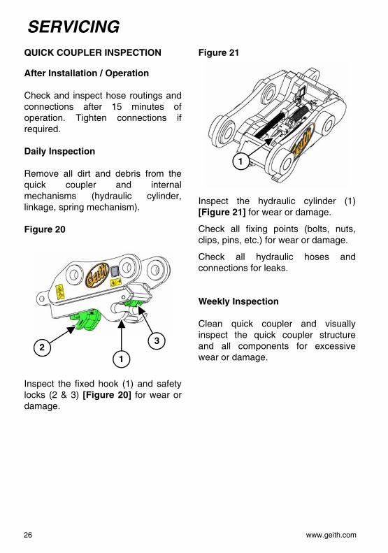
QUICK COUPLER INSPECTIONAfter Installation / Operation
Check and inspect hose routings andconnections after 15 minutes ofoperation. Tighten connections ifrequired.
Daily Inspection
Remove all dirt and debris from thequick coupler and internalmechanisms (hydraulic cylinder,linkage, spring mechanism).
Figure 20
Inspect the fixed hook (1) and safetylocks (2 & 3) [Figure 20] for wear ordamage.
Figure 21
Inspect the hydraulic cylinder (1)[Figure 21] for wear or damage.
Check all fixing points (bolts, nuts,clips, pins, etc.) for wear or damage.
Check all hydraulic hoses andconnections for leaks.
Weekly Inspection
Clean quick coupler and visuallyinspect the quick coupler structureand all components for excessivewear or damage.1
23
1
26 www.geith.com

SERVICING
PART REPLACEMENTRequired Tools
Figure 22
Hammer (1) [Figure 22].
Two Wrenches (2) [Figure 22] (Checkquick coupler for correct size).
Flat-head Screwdriver (3) [Figure 22].
Large Bolt / Punch (4) [Figure 22](10mm or 20mm).
Small Bolt / Punch (5) [Figure 22](Check quick coupler for correct size).
Removing The Quick Coupler
Partially curl in the Quick Coupler (linkpin lower than dipper pin).
Retract the quick coupler cylinder.
Figure 23
Using a small bolt / punch, remove thesafety clasp roll pin (1) [Figure 23].
Lower the quick coupler to the ground.
Figure 24
Remove machine link pin (1) [Figure24] from the quick coupler.
Retract the bucket cylinder and movethe machine linkage away from thequick coupler.
12
34
5
1
1
www.geith.com 27

SERVICING
Stop the engine and release anyhydraulic pressure in the system.Remove the hydraulic hoses from thecylinder.
Disassembly (QC60 - QC140)
Figure 25
Tighten the retaining bolt (1) [Figure25] until Guide pin end retracts fromslot..
Figure 26
Remove spring retaining boltassembly (1) [Figure 26].
Disassembly (QC35 - QC55)
Figure 27
Insert a flat head screwdriver (1)[Figure 27] at the end of the springassembly, pull back on thescrewdriver and remove the springassembly.
Figure 28
Tighten the spring retaining bolt (1)[Figure 28] until free from housing.
NOTE: Make sure the flats of thespring retainers are in linewith retaining brackets sothat it will fit into place.Some models may varyslightly in design.
1
1
1
1
28 www.geith.com

SERVICING
Figure 29Remove spring assembly (1) [Figure29].
Figure 30
Remove the locking clasp main pivotpin (1) [Figure 30].
Remove the locking clasp from thequick coupler.
Figure 31
Using a punch tool and hammer,remove the sliding hook retaining rollpins (1) [Figure 31].
Disassembly (Mechanical Coupler QC45 - QC90)
Figure 32
Remove four allen head cap screwsand bolt on guard (1) [Figure 32].
1
1
1
1
www.geith.com 29

SERVICING
Figure 33Using a punch tool and hammer,remove roll pin (1) [Figure 33].
Figure 34
Remove the nut with hole (1) [Figure34].
Figure 35
Remove the manual cylinder lock nut(1) [Figure 35].
Figure 36
Pull sliding hook out the back ofcoupler (1) [Figure 36].
1
1
1
1
30 www.geith.com

SERVICING
Figure 37Using a punch tool and hammer,remove the retaining roll pins (1)[Figure 37].
Figure 38
Remove the fixed lock bushing (1)[Figure 38].
Figure 39
Remove the moving lock bushing (1)[Figure 39].
Figure 40
Remove the compression spring (1)[Figure 40].
1
1
1
1
www.geith.com 31

SERVICING
Figure 41Using flat head screw driver removethe rubber bungs (1) [Figure 41].
Figure 42
Fully rotate the cylinder (1) [Figure42] up, then lift and remove cylinder.
NOTE: To assemble parts, repeatsteps in reverse.
1
1
32 www.geith.com

SPECIFICATIONS
SPECIFICATIONSEXCAVATOR WEIGHT(TONS)
PIN DIAMETER
(MM)
COUPLER MODEL
(H) HYDRAULIC(M) MANUAL
MIN - MAX**CENTRES
(MM)
BASE WIDTH(MM)
COUPLER WEIGHT***KG (LBS)
2-4 35/40 QC35-40 H* 130-214 122 35 (77)
3-5 40 QH40 H/M 220-355 150 65 (143)
5-7 45 QC45 H 218-394 144/150 63 (139)
5-7 45 QH45 M 220-395 150 65 (143)
6-9 50 QC50 H 235/375 160/180 72 (159)
6-9 50 QH50 M 234-385 150/180 65 (143)
7-11 55 QC55 H 315-358 160 72 (159)
7-11 55 QH55 H/M 275-316 160/180 82 (180)
11-17 60 QC60 H 280-480 210/250 150 (330)
11-17 60 QH60 M 280-480 168/250 172 (379)
11-17 65 QC65 H 355-430 220/250 171 (379)
11-17 65 QH65 M 355-430 220-250 177 (379)
15-22 70 QH70 H/M 365-490 250/280 186 (410)
16-29 80 QC80 H 385-530 280/300 285 (628)
16-29 80 QC80 M 390-525 280/300 240 (529)
24-35 90 QH90 H/M 380-610 320/325 420 (924)
30-40 100 QH100 H 500-630 370 436 (961)
33-46 110 QH110 H 535-645 390 721 (1589)
45-60 115 QH115 H 608-685 438 721 (1589)
50-65 120 QH120 H 570-635 428/468 1090 (2402)
65-70 130 QC130 H 615-790 487/527 1090 (2402)
70-87 140 QC140 H 667-785 527 1460 (3217)
* Lifting eye is optional.
** Range of centres is for combined coupler models and cannot be achieved by one coupler model.
*** Weight refers to smallest coupler in range.
www.geith.com 33

SPECIFICATIONS
34 www.geith.com

WARRANTY
WARRANTY PROGRAMThe Company warrants the Equipment (except for parts) sold by it to thePurchaser to be:
• Free of defects in material and workmanship for a period of twelve (12)months from the date of shipment or 2000 hours of use, whichever first occursunless formal documentation can be produced when the product has been putinto use. A period of six (6) months shelf life will be accepted on all products.Any product not put into use before the six (6) months stocking and twelve(12) warranty period will forfeit any warranty given on the product. The Geithgeneric installation/hose assemblies will be covered for a period of six (6)months from the date of shipment (installation kit covered only in Europe).
• The applicable warranty time period for parts shall be six (6) months from thedate of shipment and for reconditioned parts or products shall be three (3)months from the date of shipment. At the discretion of the company a longerthirty six (36) month warranty period may be offered to selected customers.This warranty period only covers the frame/chassis of the product andexcludes all other components attached to the frame/chassis.
• No warranty will be accepted for wear/damage on products or componentsthereof.
The Company will provide a new part or repaired part, at its election, in place ofany part which is found upon its inspection to be defective in material orworkmanship during the periods described above. Such part will be repaired orreplaced without charge to the Purchaser providing the warranty cost does notexceed the standard cost which has been set out by the company in the standardcost table (this cost is available upon request). The company will accept maximumwarranty costs not exceeding the original sale value.
The replacement or repair must be carried out during normal working hours at theplace of business of a distributor of the Company authorised to sell the type ofEquipment involved or other establishment authorized by the Company. Thepurchaser must report failures within a maximum time of 30 days of occurrenceand file a warranty claim within a maximum of 30 days thereafter. Warranty claimsoutside this period of time will forfeit the warranty cover.
www.geith.com 35
WARRANTY
Purchaser must present proof of purchase (and purchase date) at the time ofmaking a claim under this warranty. Warranty claims do not apply to failuresoccurring as a result of abuse, misuse, negligent repairs, corrosion, erosion,normal wear and tear, alterations or modifications (which includes use of nonGeith control systems) made to the Equipment without express written consent ofthe Company, or failure to follow the recommended operating practices, or serviceand maintenance procedures as provided in the Equipment's operating andmaintenance publications. All maintenance, service and repair work must becompleted by an authorised Company distributor or establishment and onlygenuine Company parts shall be used in such work. Failure to comply strictly withthese requirements shall invalidate this warranty. The warranty provided hereindoes not apply to any components which are not supplied by the company (thisincludes engines, hydraulic systems, boom, dipper, etc) which are manufacturedby others as they are warranted by their respective manufacturers directly to thePurchaser.THE COMPANY DISCLAIMS AND EXCLUDES ALL OTHER CONDITIONS,WARRANTIES OR REPRESENTATIONS OF ALL KINDS, EXPRESS ORIMPLIED, STATUTORY OR OTHERWISE (EXCEPT THAT OF TITLE),INCLUDING ALL IMPLIED WARRANTIES AND CONDITIONS RELATING TOMERCHANTABILITY, SATISFACTORY QUALITY AND FITNESS FOR APARTICULAR PURPOSE. Corrections by the Company of nonconformitieswhether patent or latent, in the manner and for the period of time provided aboveshall constitute fulfillment of all liabilities of the Company for such nonconformities,whether based on contract, warranty, tort, negligence, indemnity, strict liability orotherwise with respect to or arising out of such Equipment.
LIMITATION OF LIABILITY
THE REMEDIES OF THE PURCHASER SET FORTH HEREIN ARE EXCLUSIVEAND THE TOTAL LIABILITY OF THE COMPANY WITH RESPECT TO THECONTRACT OR THE EQUIPMENT AND SERVICES FURNISHEDHEREUNDER, IN CONNECTION WITH THE PERFORMANCE OR BREACHTHEREOF OR FROM THE MANUFACTURE, SALE, DELIVERY,INSTALLATION, REPAIR OR TECHNICAL DIRECTION COVERED BY ORFURNISHED UNDER THE CONTRACT, WHETHER BASED ON CONTRACT,WARRANTY, TORT, NEGLIGENCE, INDEMNITY, STRICT LIABILITY OROTHERWISE, SHALL NOT EXCEED THE PURCHASE PRICE OF THE UNIT OFEQUIPMENT UPON WHICH SUCH LIABILITY IS BASED. THE COMPANYAND ITS SUPPLIERS SHALL IN NO EVENT BE LIABLE TO THE PURCHASER,ANY SUCCESSORS IN INTEREST OR ANY BENEFICIARY OR ASSIGNEE OFTHE CONTRACT FOR ANY CONSEQUENTIAL INCIDENTAL, INDIRECT,
36 www.geith.com

WARRANTY
SPECIAL OR PUNITIVE DAMAGES ARISING OUT OF THE CONTRACT, ORANY BREACH HEREOF, OR ANY DEFECT IN, OR FAILURE OF, ORMALFUNCTION OF THE EUQIPMENT SUPPLIED HEREUNDER WHETHERBASED UPON LOSS OF USE, LOST PROFITS, REVENUE OR INTEREST,LOST GOODWILL, WORK STOPPAGE, IMPAIRMENT OF OTHER GOODS,LOSS BY REASON OF SHUTDOWN OR NON-OPERATION, INCREASEDEXPENSES OF OPERATION, COST OF PURCHASE OF REPLACEMENTPOWER OR CLAIMS OF THE PURCHASER OR CUSTOMERS OF THEPURCHASER FOR SERVICE INTERRUPTION, WHETHER OR NOT SUCHLOSS OR DAMAGE IS BASED ON CONTRACT, WARRANTY, TORT,NEGLIGENCE, INDEMNITY, STRICT LIABILITY OR OTHERWISE.VIOLATIONS OF LAW
The Company shall not be bound by or required to adhere to any term or provisionof a purchase order, quotation, bid, letter of credit or like document or anyprovision of law, regulation or custom, which would cause the Company, its parentor any of its affiliates to be in violation of or fail to comply with the export laws,taxing statutes or regulations of the country wherein the Equipment ismanufactured or from which it is exported or is otherwise subject to jurisdiction.
GOVERNING LAW
The rights and obligations of the Purchaser and the Company shall be governedand construed in accordance with the laws of the Republic of Ireland and thePurchaser submits to the exclusive jurisdiction of the Irish Courts.
MODIFICATIONS, SEVERABILITY AND ENTIRE AGREEMENT
The Company shall not be bound by any amendment or any modification to theContract until approved in writing by an officer of the Company. The Contractwhen so approved, shall supersede all previous communications, either oral orwritten. If any clause of the Contract is held by any competent authority to beinvalid or unenforceable in whole or in part, the other clauses of the Contract andthe remainder of the clause in question shall not be affected thereby.
TA detailed description of terms and conditions of sale can be found on QR39Geith terms and conditions of sale which was attached to your orderacknowledgement. If you do not have a copy you can contact your nearest GeithDistributor.
www.geith.com 37

WARRANTY
38 www.geith.com


www.geith.com
Contact us:Ireland - Geith InternationalGrangegeeth, Slane, CO. Meath, IrelandT: +353 (0)41 982 4183 F: +353 (0)41 982 [email protected]
UK - Geith International UK LtdUnit 6, Hoel - Y - Gamlas, Parc Nantgarw, Nantgarw, Cardi�, CF15 7QU, UKT: +44 (0)1443 845 666 F: +44 (0)1443 844 [email protected]
US - Geith Inc2905 Shawnee Industrial Way, Shawnee, GA 30024T: +1 866 472 4373 (Toll Free) F: +1 866 472 [email protected]
France - Agent Commercial France de Geith International Ltd203 route de Grenoble, 69800 Saint Priest, FranceNo Vert: 0800916626 F: +33 (0)4 72 79 32 [email protected]