coupling sae 2 - geislinger · design sb+bf coupling-combination the geislinger sb-coupling design...
TRANSCRIPT

GeislinGer sAe-CouplinG
CompaCt Design

Advanced com-posite membrane for oil volume expansion
New integrated skeleton for more compactness and less weight (patented).
Standardized interfac-es for SAE- Standard J620 (outside) spline connections (inside) and VSTI-plugs for quick oil exchange.
D e s c r i p t i o n
The Geislinger SAE-Coupling with its modular con-cept, enlarged oil volume and the renowned fatigue resistant steel springs permits a short lead time and attractive pricing.The SAE-Coupling is available in four different stiff-ness levels, and adapts perfectly to the stiffness and torque required by specific applications. To meet all installation situations, customized adapt-ers with splined interfaces are available to connect to the coupling inner part and allow for axial movement.The composite membrane enables thermal expan-sion of the oil and allows for a rapid oil exchange by flushing. Resistant to heat and oil, the Geislinger SAE-Coupling is the perfect solution for installation in harsh envi-ronments, such as bell or bearing carrier housings with low air ventilation.
A D vA n tA g e s
Minimal weight and slim, low profile design Compact, high power density Reduction of lead time Superior reliability is achieved using original
Geislinger-made steel springs Rapid oil exchange via VSTI-plugs Simple calculation using linear and constant parameters Longevity of coupling is unaffected
by harsh environmental stresses Low life-cycle cost Geislinger Worldwide After Sales Service
A p p l i c At i o n s
Marine Power generation Rail Mining Oil and gas
t e c h n i c A l D AtA
Torque range: 2.4 - 20 kNm Twist at nominal torque: 30, 60, 90 and 120 mrad Dimensionless damping factor: 0.07 – 0.154 Ambient temperature: -10°C to 120°C SAE-Standard J620 outer connections:
14, 18, 21 and 24 Inner connection: Spline, blind-assembly Multiple adapter options: flange, keyway or conical taper
The technology behind the Geislinger steel spring coupling with its extraordinary reliability has been proven for more than 50 years. This successful design has now been further developed and optimized, resulting in the SAE-Coupling. In circumstances where reliability and cost of ownership are decisive factors, the Geislinger SAE-Coupling is the first choice for a wide variety of applications.
GeislinGer sAe-CouplinG

Geislinger GmbH, 5300 Hallwang, Austria
Preamble
This catalog replaces all old catalog versions.
The content of this catalog is indicative and ‐ based on new developments ‐ Geislinger reserves
the right to change the content without prior notice.
All duplication, reprinting and translation rights are reserved.
Should you have questions, remarks or inquiries please contact us per e‐mail
([email protected]) or telephone (+43 662 66999‐0).
The latest version of all Geislinger catalogs can be found on our website Geislinger.com.

Geislinger SAE-Coupling
Geislinger GmbH, 5300 Hallwang, Austria SAE-Coupling Catalog Version 2.0 1 / 46 August 2018
Index
Description .................................................................................................................. 2
Designation ................................................................................................................. 8
Selection .................................................................................................................... 10
Technical Data SE-Coupling ........................................................................................ 27
SE-Couplings Series 41 ....................................................................................... 27
SE-Couplings Series 50 ....................................................................................... 28
SE-Couplings Series 60 ....................................................................................... 29
Dimensions SE-Coupling ............................................................................................ 30
Standard-Coupling Series 41 .............................................................................. 30
Standard-Coupling Series 50 .............................................................................. 31
Standard-Coupling Series 60 .............................................................................. 32
Technical Data & Dimensions SB + BF – Coupling-Combination .................................. 33
SB + BF – Coupling-Combination Series 50 ......................................................... 33
SB + BF – Coupling-Combination Series 58 ......................................................... 36
Examples ................................................................................................................... 39

Geislinger SAE-Coupling
Geislinger GmbH, 5300 Hallwang, Austria SAE-Coupling Catalog Version 2.0 2 / 46 August 2018
Description
Application
Geislinger SAE-Couplings are torsional elastic steel spring couplings with the following advantages:
Modular concept for SAE-flywheel sizes
High torsional elasticity
Torsional damping
Longest life time
Low weight, small size
No aging, easy to service
Low wear and maintenance
Indifferent to high temperatures, dirt and oil
Constant stiffness and damping over coupling life
Suitable for high rotational speeds
Due to the increased power density of today’s diesel and gas engines, more attention must be paid to torsional vibration issues. In many cases it is necessary to dampen torsional vibrations and to move damaging natural frequencies out of the operating speed range of the driven system. The Geislinger SAE-Coupling is capable of solving both of these tasks. The stiffness of the coupling leaf springs can be precisely tuned to isolate or move harmful natural frequencies. In addition the Geislinger SAE-Coupling provides a certain damping which dampens torsional vibrations. Without a SAE-Coupling these torsional vibrations create stresses in the driven system, dramatically shortening component life and reliability. The Geislinger SAE-Coupling allows for continuous operation within the operating speed range of the driven system, obtaining lower stresses in shafts and gears.
Geislinger SAE-Couplings do not only meet the demands of any type and size of internal combustion engine, but also the demands of all sorts of other machinery. Applications such as marine and pumps are typical examples. Data collection from many research tests have enabled precise torsional damping and torsional spring stiffness data to be established. This guarantees correct calculation of critical speeds, amplitudes and loads in all parts of the system. Torsional stiffness is available in narrow steps within a wide range to meet the needs of any installation.
Due to the fact that the Geislinger SE-Coupling has no axial stiffness it can easily absorb thermal expansion of the driving and driven system parts. The SE-Coupling also permits radial and angular misalignments in a small range.
For high misalignment needs in radial and axial direction the Geislinger SB-Coupling with
internal axial/radial fixation of the driven flange is combined with a Gesilco BF-Coupling. This coupling combination allows for very low reaction forces and homo-kinetic torque transmission. Adapters are tailor-made.
Geislinger SAE-Coupling
Geislinger GmbH, 5300 Hallwang, Austria SAE-Coupling Catalog Version 2.0 3 / 46 August 2018
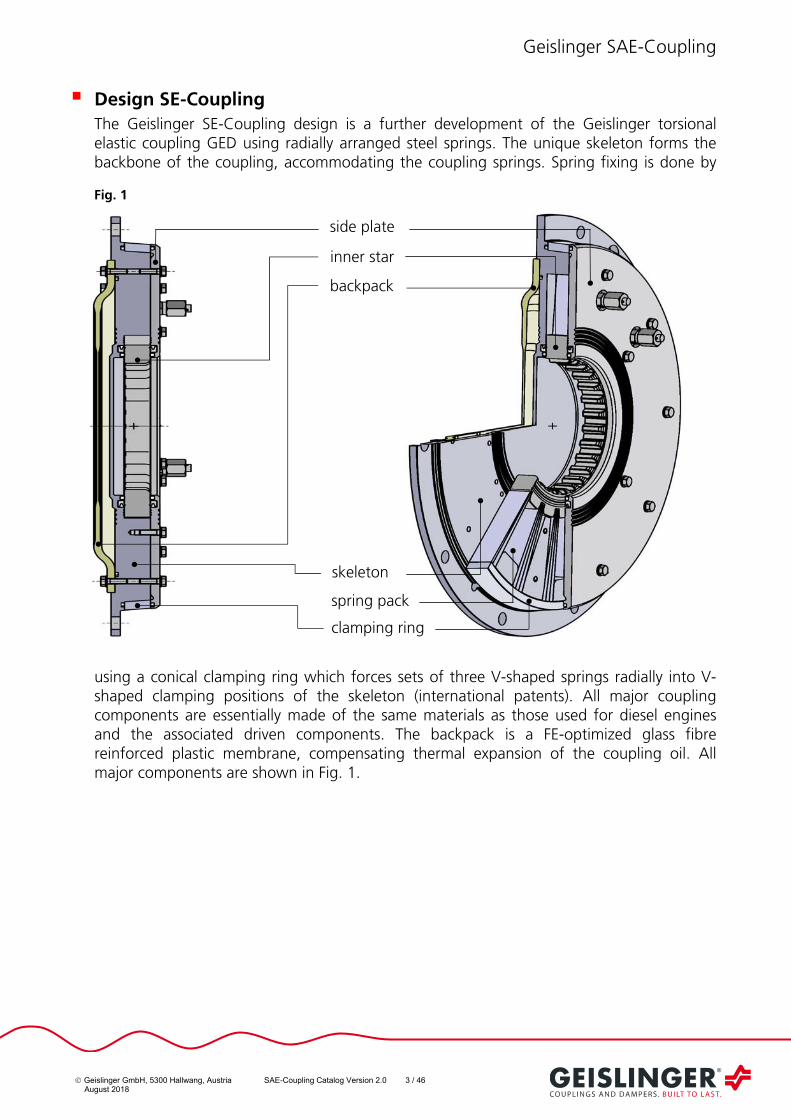
Design SE-Coupling
The Geislinger SE-Coupling design is a further development of the Geislinger torsional elastic coupling GED using radially arranged steel springs. The unique skeleton forms the backbone of the coupling, accommodating the coupling springs. Spring fixing is done by
using a conical clamping ring which forces sets of three V-shaped springs radially into V-shaped clamping positions of the skeleton (international patents). All major coupling components are essentially made of the same materials as those used for diesel engines and the associated driven components. The backpack is a FE-optimized glass fibre reinforced plastic membrane, compensating thermal expansion of the coupling oil. All major components are shown in Fig. 1.
skeleton
backpack
inner star
clamping ring
spring pack
Fig. 1
side plate

Geislinger SAE-Coupling
Geislinger GmbH, 5300 Hallwang, Austria SAE-Coupling Catalog Version 2.0 4 / 46 August 2018
Design SB+BF Coupling-Combination
The Geislinger SB-Coupling design is a further development of the Geislinger SE- Coupling using radially arranged steel springs. The unique skeleton forms the backbone of the coupling with its flange part taking over the function of the clamping ring. Spring fixation
is done by forcing sets of three V-shaped springs radially into V-shaped clamping positions of the skeleton (international patents). All major coupling components are essentially made of the same materials as those used for diesel engines and the associated driven components. The backpack is a FE-optimized glass fibre reinforced plastic membrane, compensating thermal expansion of the coupling oil.
The SB-Coupling is combined with the Gesilco BF-Coupling as a standard. The patented
Gesilco BF-Coupling consists of two membranes, an intermediate shaft with openings for assembly of fitted steel inserts and pre-stressed screws and two flanges. Membranes, intermediate shafts and flanges are manufactured as a single piece advanced composite structure.
The halves of the coupling are bolted together at the outer flanges with fitted bolts. By use of variable thickness spacers, installation tolerances and centering recesses can be compensated. At the inner flanges fitted steel inserts combined with pre-stressed screws are used to connect the BF-Coupling to the driving and driven components. All major components are shown in Fig. 2.
BF-Coupling
spring pack
Fig. 2
flange hub side plate
backpack
inner star
skeleton
flange

Geislinger SAE-Coupling
Geislinger GmbH, 5300 Hallwang, Austria SAE-Coupling Catalog Version 2.0 5 / 46 August 2018
It is possible to adjust the Gesilco BF-Coupling installation length (i.e. 3 washer thicknesses can be installed in 3 different combinations to change the overall length of the BF-Coupling. See Fig. 3):
Fig. 3
The BF-Coupling inner flange bolts are mounted through the openings with a torque spanner. See fig.4. Afterwards the coupling halves are turned into the operating position and bolted together. See fig. 5.
Fig. 4 Fig. 5
Torsional Stiffness
The steel springs represent the core components of a Geislinger SAE-Coupling. Three V-shaped springs distanced by shims create a spring pack. They are produced in four basic stiffness series and develop by using several numbers of spring packs (6, 8, 10, 12, 14, 15, 16, 18, 20) a fine graded stiffness range. The stiffness series, listed in this catalogue, form standard determinations based on the requirements of most applications.
The Gesilco BF-Coupling can be considered as more or less torsional stiff.
Openings for mounting of inner flange bolts

Geislinger SAE-Coupling
Geislinger GmbH, 5300 Hallwang, Austria SAE-Coupling Catalog Version 2.0 6 / 46 August 2018
Torsional Damping
The torsional damping of the oil filled Geislinger SAE-Coupling is mainly influenced by damping due to friction between the springs and between springs and inner star grooves, as the effect of hydrodynamic damping is set very low.
Misalignment
Axial Misalignment
The Geislinger SE-Coupling provides axial displacement capacity due to a splined connection between innerstar and the driven part. It enables absorption of axial thermal expansion of drive shaft components. In addition, the coupling’s axial displacement capacity allows blind assembly and removal of any driven arrangement without disassembly of surrounding components.
The Geislinger SB+BF-Coupling-Combination provides axial displacement capacity due to
the properties of the Gesilco BF-Coupling. Each Gesilco membrane is able to compensate for axial misalignments. Reaction forces caused by axial deflections are nearly linear within a wide range.
The values for axial displacement are mentioned in the Technical Data tables.
Radial and Angular Misalignment
For the Geislinger SE-Coupling radial and angular misalignment capacity of the coupling is
determined by the size of gap rK . Resulting reaction forces are determined by the
stiffness of the coupling springs and are relatively small. Most importantly, no permanent deformation is occurring during misalignment compensation. This is due to the fact that loads are absorbed elastically by the spring packs.
For the Geislinger SB+BF-Coupling-Combination radial and angular misalignment capacity
are determined by the properties of the Gesilco BF-Coupling. In radial direction, a single
Gesilco membrane is relatively stiff.
The combination of two membranes, coupled by a given length, allows for compensation of radial, angular and axial misalignments. Reaction forces caused by axial and angular deflections are nearly linear within a wide range.
Misalignment values can be seen in the Technical Data tables.
Assembly
The SAE-Coupling is designed for standard connection of SAE-flywheel size 14, size 18, size 21 and size 24. In the same configuration there are also connection solutions available for nonstandard metric connecting bolts and/or for a different number of connecting bolts.
Geislinger SAE-Coupling
Geislinger GmbH, 5300 Hallwang, Austria SAE-Coupling Catalog Version 2.0 7 / 46 August 2018
The driven part of the SE-Coupling can connect directly to the coupling’s inner spline or an adapter can be used for connecting a tapered shaft, a keyway shaft or a flange shaft. Even in the most difficult situations, assembly is possible through design optimization of an adapter.
The driven part of the SB+BF-Coupling -Combination can connect directly to the BF-flange or a tapered hub, a keyway hub or a flange hub can be provided with customized dimensions.
Overload Capability
Due to the SAE-Coupling’s design, half or all of the spring packs come in contact with the spring bending limitation at 1.4 times of the nominal torque. This is referred to as torque on buffer. The coupling’s standard design enables it to transmit transient shock torques up to 3.25 times of the nominal torque. With respect to marine applications, the spring bending limitations can help the coupling to act as a rigid coupling or as "homecoming device" if some spring packs are damaged.
Oil Supply
The Geislinger SAE-Coupling is oil filled directly after the assembly process. There are 2 connections for a quick oil change available on the sideplate or the skeleton of the coupling. Oil change is done by flushing a certain oil volume through the coupling. Oil change intervals and a detailed description of the oil change process are mentioned in the coupling’s manual.
Approval
All couplings are produced and certified in accordance with quality assurance requirements of DIN/ISO 9001 and DIN/ISO 14001. Geislinger’s Quality Assurance System has been certified by all major classification societies.
All couplings can be supplied with approvals of major classification societies. Those classification society approvals do not require design alterations or compulsory spare parts.
For survey by a classification society, the following information is requested:
Name of Classification Society
Shipyard
Hull number
Geislinger SAE-Coupling
Geislinger GmbH, 5300 Hallwang, Austria SAE-Coupling Catalog Version 2.0 8 / 46 August 2018
Designation
Designation Code
In order to produce the Geislinger SAE-couplings as small and cost effective as possible, very soft couplings are designed as non-reversible couplings.
Non-Reversible Type NC3
This design is used with non-reversible engines. It has asymmetric bending capacity in forward and reverse direction.
Reversible Type UC3
This design has a symmetric spring bending capacity in the forward and reverse direction.
It can be used for reversible engines. In reverse direction, this coupling can transmit the
same torque as in forward direction ( KNT. 01 ).
The SE-Coupling designation has the following meaning:
SE 41/2.2/120NC3/1/L/20/S14
SE: SAE-type of engine flywheel. Inner connection of the SE-Coupling is a standardized spline connection. Different adaptors fitting to the spline connection are available on request.
41: Outer diameter of centre part in cm 2.2: Spring pack width in cm 120: Stiffness series and the approximate twist in mrad at nominal torque.
Standard series are 30, 60, 90 and 120. Torsional stiffness and nominal torque can be varied by different number of spring packs.
NC3, UC3: Directionality code for coupling type with 3-spring design NC3 non-reversible UC3 reversible
L: Left hand coupling rotation when looking to the side plate, if torque input from coupling outer part.
R: Right hand coupling rotation when looking to the side plate, if torque input from inner star.
1/L: Left hand coupling rotation when looking to the side plate, if torque input from inner star.
1/R: Right hand coupling rotation when looking to the side plate, if torque input from coupling outer part.
20: Number of spring packs per coupling (8, 10, 12, 14, 15, 16, 18 or 20) S14: Connection fitting for SAE-flywheel S14 : fitting for SAE-flywheel size 14 (flange drillings for SAE- inch bolts) M14/..: fitting for SAE-flywheel size 14 (with customized drillings)
Geislinger SAE-Coupling
Geislinger GmbH, 5300 Hallwang, Austria SAE-Coupling Catalog Version 2.0 9 / 46 August 2018
The SB+BF-Coupling-Combination designation has the following meaning:
SB 50/2.2/120NC3/1/L/20/S14 + BF 50/50/2USO
SB: SAE-type of engine flywheel. The SB-Coupling with its innerstar fixation is
always combined with the Gesilco BF-Coupling connecting to a customized flange hub.
50: Outer diameter of centre part in cm 2.2: Spring pack width in cm 120: Stiffness series and the approximate twist in mrad at nominal torque.
Standard series are 60, 90 and 120. Torsional stiffness and nominal torque can be varied by different number of spring packs.
NC3, UC3: Directionality code for coupling type with 3-spring design NC3 non-reversible UC3 reversible
L: Left hand coupling rotation when looking to the side plate if torque input from coupling outer part.
R: Right hand coupling rotation when looking to the side plate if torque input from inner star.
1/L: Left hand coupling rotation when looking to the side plate if torque input from inner star.
1/R: Right hand coupling rotation when looking to the side plate if torque input from coupling outer part.
20: Number of spring packs per coupling (8, 10, 12, 14, 15, 16, 18 or 20) S14: Connection fitting for SAE-flywheel S14 : fitting for SAE-flywheel size 14 (flange drillings for SAE- inch bolts) M14/..: fitting for SAE-flywheel size 14 (with customized drillings)
BF 50/50/2USO
BF Gesilco BF-Coupling consisting of 2 symmetrical coupling halves 50 nominal outside diameter of the coupling in cm 50 stiffness series 2 number of membranes U reversible S manufacturing technique O 3 openings between the 2 coupling halves for assembly of inner flange bolts

Geislinger SAE-Coupling
Geislinger GmbH, 5300 Hallwang, Austria SAE-Coupling Catalog Version 2.0 10 / 46 August 2018
Selection
Technical data for each SAE-Coupling, depending on the outer diameter of the centre part, width of the spring packs, stiffness of the spring packs and directionality code for the coupling type, can be selected from the technical data sheets.
Type NC3, UC3
Based on the application, it is necessary to determine whether a reversible or non-reversible coupling is required.
Torsional stiffer reversible coupling series (series 30UC3, series 60UC3) are selected as a first approach for generating sets, pump drives or other industrial applications, whereas torsional softer non reversible coupling series (series 90NC3, series 120NC3) are mainly considered for marine applications.
Nominal Torque KNT
The mean torque T is calculated from the engine power P and rotational speed n
n
PT 55.9
T mean torque kNm P engine power kW n rotational speed min-1
The coupling size should be selected in order that the coupling's nominal torque KNT is
greater or equal to the maximum mean torque T in the engine operating speed range specified by the prime mover or application.
TTKN >
Stiffness Series
Four different basic torsional stiffness series are listed in this catalog (series 30, 60, 90 and 120). In order to transmit the same nominal torque
KNT a wider coupling is required for a
torsional softer coupling (series 120) than for a stiffer coupling (series 90).
In addition the number of spring packs (6, 8, 10, 12, 14, 15, 16, 18 and 20) can be varied in narrow steps for each stiffness series. By that a fine graded stiffness range is achieved.

Geislinger SAE-Coupling
Geislinger GmbH, 5300 Hallwang, Austria SAE-Coupling Catalog Version 2.0 11 / 46 August 2018
The following comparison illustrates the dependence of the coupling width on choice of stiffness for the same nominal torque KNT .
SE 41/1.4/90NC3/20/.. KNT = 6 kNm
SE 41/2.2/120NC3/20/.. KNT = 6 kNm
For an initial calculation it is recommended that a torsional stiffer coupling is selected. The torsional stiffer reversible coupling series 30UC3 or 60UC3 are selected as a first approach for generating sets, pump drives or other industrial applications, whereas the torsional softer non reversible coupling series 90NC3 or 120NC3 are mainly used for marine applications.
A torsional vibration calculation must be performed to confirm that a selected stiffness is suitable for a given application. The calculation must use the excitations of the total system and must be performed for all possible operating conditions (normal operation, misfiring of one cylinder, etc.) and speeds.
For these calculations, it is necessary to use the damping factor .
From the analyses results, for instance the vibratory torques can be determined. These consist of damping and elastic components and must be checked against the permitted values as described in the following chapters.
Stiffness:
This is the torsional stiffness value at a static nominal torque. It is shown in the Technical Data sheets as C . For a Geislinger SAE-Coupling the static stiffness is practically constant.
Geislinger SAE-Coupling
Geislinger GmbH, 5300 Hallwang, Austria SAE-Coupling Catalog Version 2.0 12 / 46 August 2018
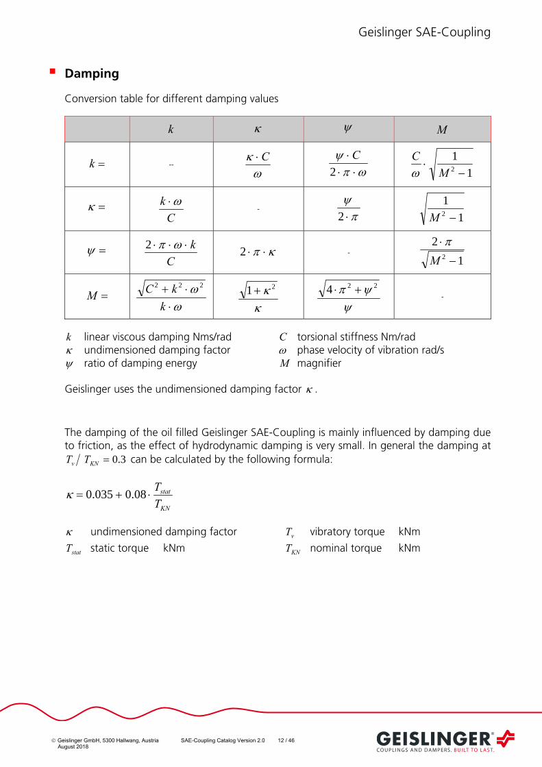
Damping
Conversion table for different damping values
k M
k --
C
2
C
1
12
M
C
C
k -
2
1
12 M
C
k 2 2 -
1
22
M
M
k
kC 222
21
224
-
k linear viscous damping Nms/rad C torsional stiffness Nm/rad undimensioned damping factor phase velocity of vibration rad/s ratio of damping energy M magnifier
Geislinger uses the undimensioned damping factor .
The damping of the oil filled Geislinger SAE-Coupling is mainly influenced by damping due to friction, as the effect of hydrodynamic damping is very small. In general the damping at
3.0KNv TT can be calculated by the following formula:
KN
stat
T
T 08.0035.0
undimensioned damping factor vT vibratory torque kNm
statT static torque kNm KNT nominal torque kNm
Geislinger SAE-Coupling
Geislinger GmbH, 5300 Hallwang, Austria SAE-Coupling Catalog Version 2.0 13 / 46 August 2018
Permissible Elastic Vibratory Torque elT
From a total vibratory torque vT , which is transmitted by the coupling only the elastic
component elT is important to be considered.
21
1
vel TT
elT elastic vibratory torque kNm vT vibratory torque kNm
undimensioned damping factor
This calculation has to be made for each harmonic order and the synthesis value has to be derived.
Permissible elastic vibratory torques, for each coupling directionality type can be seen in the following diagrams. The diagrams show:
- the limits for elastic vibratory torques, which momentarily occur (e.g. transient condition),
- the limits for continuous permissible elastic vibratory torques and
- the vibratory torque on buffer (not valid for Gesilco BF-Coupling).
Geislinger SAE-Coupling
Geislinger GmbH, 5300 Hallwang, Austria SAE-Coupling Catalog Version 2.0 14 / 46 August 2018
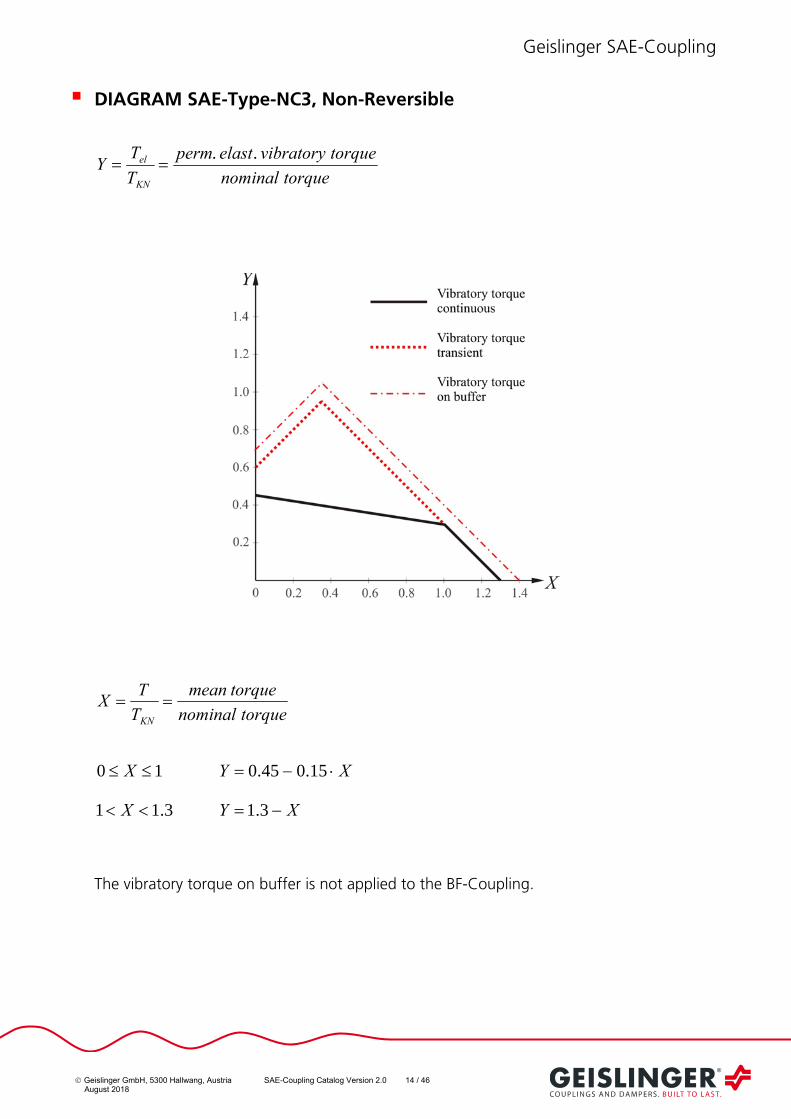
DIAGRAM SAE-Type-NC3, Non-Reversible
torqueinalnom
torquevibratoryelastperm
T
TY
KN
el ..
torqueinalnom
torquemean
T
TX
KN
10 X XY 15.045.0
3.11 X XY 3.1
The vibratory torque on buffer is not applied to the BF-Coupling.

Geislinger SAE-Coupling
Geislinger GmbH, 5300 Hallwang, Austria SAE-Coupling Catalog Version 2.0 15 / 46 August 2018
DIAGRAM SAE-Type-UC3, BF-Type-USO, Reversible
torqueinalnom
torquevibratoryelastperm
T
TY
KN
el ..
torqueinalnom
torquemean
T
TX
KN
Reverse 10 X 32 07209.004432.008354.05.0 XXXY
3.11 X XY 3.1
Forward 10 X 32 07209.004432.008354.05.0 XXXY
3.11 X XY 3.1
The vibratory torque on buffer is not applied to the BF-Coupling.
Geislinger SAE-Coupling
Geislinger GmbH, 5300 Hallwang, Austria SAE-Coupling Catalog Version 2.0 16 / 46 August 2018
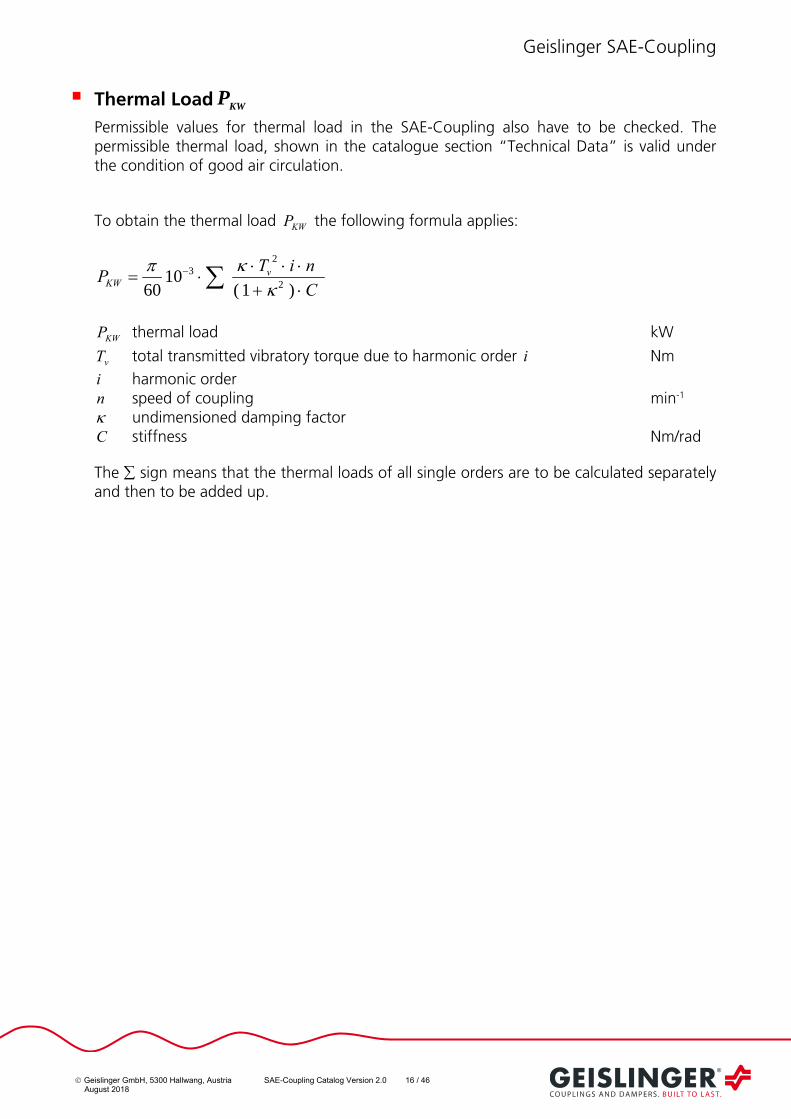
Thermal Load KWP
Permissible values for thermal load in the SAE-Coupling also have to be checked. The permissible thermal load, shown in the catalogue section “Technical Data” is valid under the condition of good air circulation.
To obtain the thermal load KWP the following formula applies:
C
niTP v
KW )1(10
60 2
23
KWP thermal load kW
vT total transmitted vibratory torque due to harmonic order i Nm
i harmonic order n speed of coupling min-1 undimensioned damping factor C stiffness Nm/rad
The sign means that the thermal loads of all single orders are to be calculated separately and then to be added up.

Geislinger SAE-Coupling
Geislinger GmbH, 5300 Hallwang, Austria SAE-Coupling Catalog Version 2.0 17 / 46 August 2018
Permissible Transient Shock Torques
The coupling can transmit transient shock torques up to the maximum torque. It should be noted that if the nominal torque of the SAE-Coupling is exceeded by more than 1.4 times the coupling is approximately 10 times torsional stiffer. The maximum transient torque for the SAE-Coupling is at least 3.25 times of the nominal torque, and 2.5 times of the
nominal torque for the Gesilco BF-Coupling.
Fig. 6 shows the relationship between SAE-Coupling twist (in mrad) and torque.
Fig. 6

Geislinger SAE-Coupling
Geislinger GmbH, 5300 Hallwang, Austria SAE-Coupling Catalog Version 2.0 18 / 46 August 2018
Permissible Misalignment Values of SE-Couplings
It is also necessary to ensure that the permissible radial, axial and angular misalignment capabilities of the coupling are not exceeded during operation.
Axial Misalignment: aW
An axial misalignment aW is the deviation from the theoretical nominal length of the
coupling. This deviation in length is caused by axial displacements of the adjoining shafts. Reasons for axial displacements include: errors in assembly distances, shaft movements or thermal expansion.
aK is the maximum permissible axial misalignment capacity of the coupling and must not
be exceeded during operation. aK is determined by the sum of static and dynamic
misalignments.
Radial Misalignment: rW
Radial misalignment rW is the misalignment of the driving side to the driven side in a
direction perpendicular to the axis of rotation. The reasons for radial misalignment include: errors in assembly alignment, shaft movements or thermal expansion.
rK is the maximum permissible radial misalignment capacity of the coupling and must
not be exceeded during operation. rK is determined by the sum of static and dynamic
misalignments.
Radial misalignments are independent of rotational speed. The relationship between radial misalignment and angular misalignment is described below in the section titled “Angular Misalignment”.
Angular Misalignment: wW
An angular misalignment wW is the inclination of the axis of rotation of the driving and
the driven side of the coupling. wK is the maximum permissible angular misalignment
capacity of the coupling and is only valid when used in conjunction with the given values for the maximum axial misalignment. The following equation should be noted in the case
of simultaneous radial misalignment rW and angular misalignment wW .
rww
rr KW
K
KW
rW actual radial misalignment mm
wW actual angular misalignment mrad
wK max. angular misalignment in accordance with the Technical Data sheet mrad
rK max. radial misalignment in accordance with the Technical Data sheet mm

Geislinger SAE-Coupling
Geislinger GmbH, 5300 Hallwang, Austria SAE-Coupling Catalog Version 2.0 19 / 46 August 2018
Axial Reaction Force aF of SE-Couplings
The axial reaction force aF is a reaction force, which occurs during axial movement of the
coupling under nominal torque. After the coupling has moved in response to an axial force, the coupling’s reaction force returns to zero. The axial reaction force does not depend on the magnitude of the axial movement.
Radial Stiffness rC of SE-Couplings
As a result of radial misalignments, radial reaction forces rF are produced. These forces
affect the driving and the driven side of the coupling.
rrr WCF
rF radial reaction force kN
rC radial stiffness kN/mm
rW radial misalignment mm
Bending Stiffness wC of SE-Couplings
Angular misalignments produce a reaction torque wM that affects the driving and driven
side of the coupling.
www WCM
wM reaction torque Nm
wC bending stiffness kNm/rad
wW angular misalignment mrad

Geislinger SAE-Coupling
Geislinger GmbH, 5300 Hallwang, Austria SAE-Coupling Catalog Version 2.0 20 / 46 August 2018
Permissible Misalignment Values of SB+BF-Coupling-Combinations
The SB-Coupling of these coupling combinations is equipped with innerstar fixations, thus all misalignment compensation is handled by the BF-Coupling. The BF- coupling’s lifetime can be theoretically determined by analyzing application load spectrum data (magnitudes and frequencies). In fact, misalignment capacities of the BF-Coupling are defined by predetermined load cycle values. Therefore, the following data tables show angular deflection capacities (transient and continuous) along with their corresponding load cycles. Since the correct coupling selection is predominately influenced by the expected lifetime or load cycles, it is very important to determine accurate values for the required transient and continuous deflections. Permissible combinations of angular and axial deformation of the coupling can be calculated using the formulas in the chapter “Calculation of the Maximum Misalignment Capacity”.
Axial Misalignment
An axial misalignment Wa is the deviation from the theoretical nominal length of the coupling. This deviation in length is caused by axial displacements of the adjoining shafts. Reasons for axial displacements include: errors in assembly distances, shaft movements,
variations in foundations (i.e. resiliently mounted engines), or thermal expansion. Ka, max
(transient) is the maximum permissible axial misalignment capacity of one membrane and must not be exceeded during operation. Using the formula given in the selection
guidelines, Ka, max can be calculated from the maximum permissible angular deflection
capacity Kw, max (transient) and the geometry parameter i of the membrane.
Radial Misalignment
Radial misalignment Wr is the movement between driving and the driven shafts in a
perpendicular direction (radial) to the axis of rotation. Radial misalignments can only be
accommodated by use of two membranes with angular deflection capacity Kw. Causes
for radial misalignment are: assembly errors, shaft displacements, thermal expansions or elastically mounted driving or driven shafts.
Kw, max (transient) is the maximum permissible angular deflection capacity of one
membrane and must not be exceeded by static and dynamic misalignments during operation. The maximum permissible radial misalignment capacity of the coupling depends on the bending length Lb (distance between the planes of the membranes). Based on the
bending length Lb , Kw, max (transient) and the following formulas, the maximum
permissible misalignment capacity can be determined.
Angular Misalignment
The angular misalignment Ww is defined as the inclination of the axis of rotation between
the driving- and the driven-side of the coupling. Angular misalignment Ww can be
compensated by using one membrane with a given angular deflection capacity Kw.
Kw, max (transient) is defined as the maximum permissible angular deflection of one
membrane and should not be exceeded during operation. The relationship between axial and angular misalignments is shown in the formulae of the following chapter.
Geislinger SAE-Coupling
Geislinger GmbH, 5300 Hallwang, Austria SAE-Coupling Catalog Version 2.0 21 / 46 August 2018
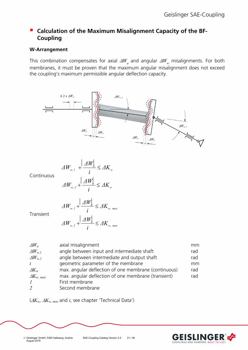
Calculation of the Maximum Misalignment Capacity of the BF-Coupling
W-Arrangement
This combination compensates for axial Wa and angular W
w misalignments. For both
membranes, it must be proven that the maximum angular misalignment does not exceed the coupling’s maximum permissible angular deflection capacity.
Continuous
wa
2w,
wa
1w,
ΔKi
ΔWΔW
ΔKi
ΔWΔW
Transient
max ,wa
2w,
max ,wa
1w,
ΔKi
ΔWΔW
ΔKi
ΔWΔW
Wa axial misalignment mm Ww,1 angle between input and intermediate shaft rad Ww,2 angle between intermediate and output shaft rad i geometric parameter of the membrane mm Kw max. angular deflection of one membrane (continuous) rad Kw, max max. angular deflection of one membrane (transient) rad 1 First membrane 2 Second membrane (Kw, Kw, max and i, see chapter ‘Technical Data’)
Wa Ww, 2
2 x Wa Ww, 1
Wa
Wa Wa

Geislinger SAE-Coupling
Geislinger GmbH, 5300 Hallwang, Austria SAE-Coupling Catalog Version 2.0 22 / 46 August 2018
Z-Arrangement
This combination compensates axial Wa and radial W
r misalignments
Continuous wa
b
r ΔKi
ΔW
L
ΔW
Transient max ,wa
b
r ΔKi
ΔW
L
ΔW
Wa axial misalignment mm Ww angular misalignment rad Wr radial misalignment mm i geometric parameter of the membrane mm Kw max. angular deflection of one membrane (continuous) rad Kw, max max. angular deflection of one membrane (transient) rad Lb bending length of the coupling mm
2 x Wa Ww
Wa
Wr
Wa Wa Wa
Lb
Geislinger SAE-Coupling
Geislinger GmbH, 5300 Hallwang, Austria SAE-Coupling Catalog Version 2.0 23 / 46 August 2018
Membrane`s Spring Rates
Torsional Stiffness CT
The BF-Coupling can be considered as torsional stiff. Values for the torsional stiffness of membranes and intermediate shafts are given in the ‘Technical Data’ section.
Bending Stiffness Cw
The angular deflection Ww of one BF-membrane produces a reaction moment M
b which
acts as a bending moment on the driving and driven shafts. The bending moment is proportional to the bending stiffness C
w of the membrane.
The reaction moment Mb can be calculated as follows:
Mb = C
w W
w
Mb reaction moment kNm Cw bending stiffness kNm/rad Ww angular deflection rad
Axial Stiffness Ca
The axial deflection Wa of the BF-membrane produces a reaction force F
a which acts as an
axial force on the driving and driven shafts. The axial force is proportional to the axial stiffness C
a of the membrane.
Fa = C
a W
a
Fa axial reaction force N Ca axial stiffness N/mm Wa axial deflection mm

Geislinger SAE-Coupling
Geislinger GmbH, 5300 Hallwang, Austria SAE-Coupling Catalog Version 2.0 24 / 46 August 2018
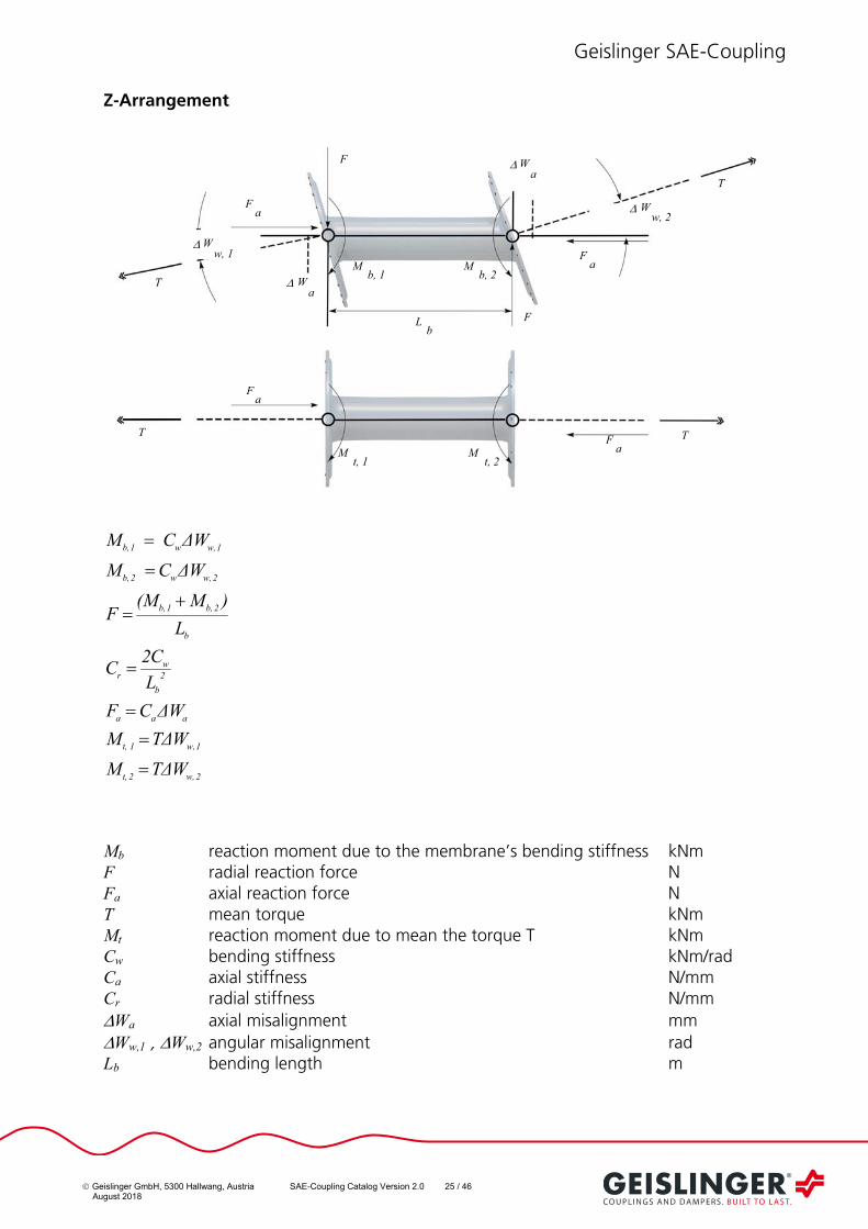
Reaction Forces of Different BF-Coupling Deflection Arrangements
In the following chapter, the calculation of membrane reaction forces, due to torque and elastic deflection, are shown for different BF-Coupling deflection arrangements.
W-Arrangement
2w,2t,
1w,1t,
aaa
b
2b,1b,
2w,w2b,
1w,w1b,
WTΔM
WTΔM
ΔWCF
L
)M(MF
ΔWC M
ΔW C M
Mb reaction moment due to the membrane`s bending stiffness kNm F radial reaction force N F
a axial reaction force N
T mean torque kNm M
t reaction moment due to the mean torque T kNm
Cw bending stiffness kNm/rad
Ca axial stiffness N/mm
Wa axial misalignment mm
Ww,1 , Ww,2 angular misalignment rad
Lb bending length m
F
Mb1
Lb
Ww2
Wa
Mb2
F W a
F a
W w1
Fa
T
T
Mt1
Mt2
F a
Fa
T
F
Mb, 1
Lb
W w, 2
Wa
Mb, 2
F
W a
F a
W w, 1
F a
T
T
Mt, 1
Mt, 2
F a
F a
T
T
Geislinger SAE-Coupling
Geislinger GmbH, 5300 Hallwang, Austria SAE-Coupling Catalog Version 2.0 25 / 46 August 2018
Z-Arrangement
2w,2t,
1w,1t,
aaa
2
b
wr
b
2b,1b,
2w,w2b,
1w,w1b,
WTΔM
WTΔM
ΔWCF
L
C2C
L
)M(MF
ΔWC M
ΔW C M
Mb reaction moment due to the membrane’s bending stiffness kNm F radial reaction force N Fa axial reaction force N T mean torque kNm Mt reaction moment due to mean the torque T kNm Cw bending stiffness kNm/rad Ca axial stiffness N/mm Cr radial stiffness N/mm Wa axial misalignment mm
Ww,1 , Ww,2 angular misalignment rad Lb bending length m
Mb, 1
Lb
W w, 2
Wa
Mb, 2
W a
F a
W w, 1 F
a
T
T
M t, 1
Mt, 2
F a
T F
a T
F
F

Geislinger SAE-Coupling
Geislinger GmbH, 5300 Hallwang, Austria SAE-Coupling Catalog Version 2.0 26 / 46 August 2018
Maximum Rotational Speed nmax
The maximum permissible speed is given in the ‘Technical Data’ section.
Temperature and Humidity
Proper selection of raw materials for the couplings depends on the desired service temperature and humidity. Normally, the couplings are designed for an ambient temperature of 80°C continuous engine room operation and 100°C for short term engine room environment. Higher temperature resistant raw materials can be delivered upon request.
Connections
Connection to flywheel:
The Geislinger standard SAE-coupling (designation…/S..) is designed with a standard flange and drillings used for inch-bolts fitting to the standardized SAE-flywheels.
If metric bolts are used instead of inch bolts or the bolt size or the number of connecting bolts is differing from the SAE-standard then a Geislinger SAE-coupling can be ordered with customized drillings for the bolts (designation …/M../.).
In any case the customer has the responsibility for the bolt connection. The sum of the maximum static torque, the maximum vibratory torque according to the torsional vibration calculation, other maximum eventually occurring peak torques like arising from gearbox clutch engagement, reaction forces and static and dynamic forces when an additional mass moment of inertia is attached to the flywheel bolt connection have to be considered multiplied with a certain safety factor. When required by classification societies the connection must be designed to meet the respective classification rules.
Connection to driving side:
The spline connection of the SE-Coupling to the driven part is standardized and cannot be changed. If a connection differing from the standard spline is needed, please contact Geislinger for offering a customized adapter.
In order to connect the BF-Coupling to a flange or shaft by the best possible method, predefined flange designs are available. In addition, Geislinger is always prepared to manufacture other connections, if economically and technically feasible. Should other assembly dimensions be required, please contact Geislinger. The type of the adapter will have an effect on the torsional vibration behaviour of the system.

Geislinger SAE-Coupling
Geislinger GmbH, 5300 Hallwang, Austria SAE-Coupling Catalog Version 2.0 27 / 46 August 2018
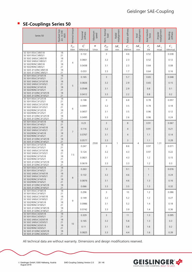
Technical Data SE-Coupling
SE-Couplings Series 41
Series 41
Flyw
heel S
ize
acc
. to
SA
E J
62
0
Nom
inal
torq
ue
To
rsio
nal
stiffn
ess
Maxi
mu
m s
peed
Perm
. th
erm
al
load
Rad
ial
mis
alig
nm
en
t
Rad
ial s
tiff
nes
s
Axi
al
mis
alig
nm
en
t
Axi
al r
eact
ion
forc
e
Angula
r m
isalig
nm
en
t
Ben
din
g
stiffn
ess
KNT C n
KWP rK
rC aK
aF wK
wC
kNm MNm/rad 1/min kW mm kN/mm mm kN mrad kNm/rad
SE 41/1/30UC3/8/S14 SE 41/1/30UC3/8/S18
14 18
2.4
0.074
2500
2
1
4.2
3
0.38
1.31
0.035
SE 41/2/60UC3/8/S14 SE 41/2/60UC3/8/S18
14 18
0.0395 2.1 2.1 0.39 0.068
SE 41/1.4/90NC3/8/S14 SE 41/1.4/90NC3/8/S18
14 18
0.0264 2.1 2.4 0.5 0.038
SE 41/2.2/120NC3/8/S14 SE 41/2.2/120NC3/8/S18
14 18
0.0198 2.1 1.9 0.51 0.076
SE 41/1/30UC3/10/S14 SE 41/1/30UC3/10/S18
14 18
3
0.0988 2 5.2 0.48 0.044
SE 41/2/60UC3/10/S14 SE 41/2/60UC3/10/S18
14 18
0.0493 2.1 2.6 0.48 0.085
SE 41/1.4/90NC3/10/S14 SE 41/1.4/90NC3/10/S18
14 18
0.033 2.1 3 0.63 0.047
SE 41/2.2/120NC3/10/S14 SE 41/2.2/120NC3/10/S18
14 18
0.0247 2.1 2.4 0.64 0.095
SE 41/1/30UC3/12/S14 SE 41/1/30UC3/12/S18
14 18
3.6
0.119 2 6.3 0.58 0.052
SE 41/2/60UC3/12/S14 SE 41/2/60UC3/12/S18
14 18
0.0592 2.1 3.2 0.58 0.1
SE 41/1.4/90NC3/12/S14 SE 41/1.4/90NC3/12/S18
14 18
0.0397 2.1 3.6 0.76 0.057
SE 41/2.2/120NC3/12/S14 SE 41/2.2/120NC3/12/S18
14 18
0.0297 2.1 2.8 0.77 0.11
SE 41/1/30UC3/14/S14 SE 41/1/30UC3/14/S18
14 18
4.2
0.138 2 7.3 0.67 0.061
SE 41/2/60UC3/14/S14 SE 41/2/60UC3/14/S18
14 18
0.069 2.1 3.7 0.67 0.12
SE 41/1.4/90NC3/14/S14 SE 41/1.4/90NC3/14/S18
14 18
0.0463 2.1 4.3 0.88 0.066
SE 41/2.2/120NC3/14/S14 SE 41/2.2/120NC3/14/S18
14 18
0.0346 2.1 3.3 0.9 0.13
SE 41/1/30UC3/15/S14 SE 41/1/30UC3/15/S18
14 18
4.5
0.148 2 7.9 0.72 0.065
SE 41/2/60UC3/15/S14 SE 41/2/60UC3/15/S18
14 18
0.074 2.1 4 0.72 0.13
SE 41/1.4/90NC3/15/S14 SE 41/1.4/90NC3/15/S18
14 18
0.0496 2.1 4.6 0.95 0.071
SE 41/2.2/120NC3/15/S14 SE 41/2.2/120NC3/15/S18
14 18
0.0371 2.1 3.5 0.96 0.14
SE 41/1/30UC3/16/S14 SE 41/1/30UC3/16/S18
14 18
4.8
0.158 2 8.4 0.77 0.07
SE 41/2/60UC3/16/S14 SE 41/2/60UC3/16/S18
14 18
0.0789 2.1 4.2 0.77 0.14
SE 41/1.4/90NC3/16/S14 SE 41/1.4/90NC3/16/S18
14 18
0.0529 2.1 4.9 1 0.076
SE 41/2.2/120NC3/16/S14 SE 41/2.2/120NC3/16/S18
14 18
0.0396 2.1 3.8 1 0.15
SE 41/1/30UC3/18/S14 SE 41/1/30UC3/18/S18
14 18
5.4
0.178 2 9.4 0.86 0.079
SE 41/2/60UC3/18/S14 SE 41/2/60UC3/18/S18
14 18
0.0888 2.1 4.8 0.87 0.15
SE 41/1.4/90NC3/18/S14 SE 41/1.4/90NC3/18/S18
14 18
0.0595 2.1 5.5 1.1 0.085
SE 41/2.2/120NC3/18/S14 SE 41/2.2/120NC3/18/S18
14 18
0.0445 2.1 4.2 1.2 0.17
SE 41/1/30UC3/20/S14 SE 41/1/30UC3/20/S18
14 18
6
0.198 2 10 0.96 0.087
SE 41/2/60UC3/20/S14 SE 41/2/60UC3/20/S18
14 18
0.0986 2.1 5.3 0.96 0.17
SE 41/1.4/90NC3/20/S14 SE 41/1.4/90NC3/20/S18
14 18
0.0661 2.1 6.1 1.3 0.094
SE 41/2.2/120NC3/20/S14 SE 41/2.2/120NC3/20/S18
14 18
0.0494 2.1 4.7 1.3 0.19
All technical data are without warranty. Dimensions and design modifications reserved.
Geislinger SAE-Coupling
Geislinger GmbH, 5300 Hallwang, Austria SAE-Coupling Catalog Version 2.0 28 / 46 August 2018
SE-Couplings Series 50
Series 50
Flyw
heel S
ize
acc
. to
SA
E
J620
Nom
inal
torq
ue
To
rsio
nal
stiffn
ess
Maxi
mu
m
spee
d
Perm
. th
erm
al
load
Rad
ial
mis
alig
nm
ent
Radia
l stiff
nes
s
Axi
al
mis
alig
nm
ent
Axi
al r
eact
ion
forc
e
Angula
r m
isalig
nm
ent
Ben
din
g
stiffn
ess
KNT C n
KWP rK
rC aK
aF wK
wC
kNm MNm/rad 1/min kW mm kN/mm mm kN mrad kNm/rad
SE 50/1/30UC3/8/S18 SE 50/1/30UC3/8/S21
18 21
4
0.132
2500
3
1
4.6
4
0.52
1.31
0.038
SE 50/2.5/60UC3/8/S18 SE 50/2.5/60UC3/8/S21
18 21
0.0661 3.2 2.3 0.52 0.12
SE 50/2/90NC3/8/S18 SE 50/2/90NC3/8/S21
18 21
0.0438 3.1 2.3 0.64 0.08
SE 50/3.3/120NC3/8/S18 SE 50/3.3/120NC3/8/S21
18 21
0.033 3.3 1.7 0.64 0.16
SE 50/1/30UC3/10/S18 SE 50/1/30UC3/10/S21
18 21
5
0.165 3 5.7 0.65 0.048
SE 50/2.5/60UC3/10/S18 SE 50/2.5/60UC3/10/S21
18 21
0.0826 3.2 2.9 0.65 0.15
SE 50/2/90NC3/10/S18 SE 50/2/90NC3/10/S21
18 21
0.0548 3.1 2.9 0.8 0.1
SE 50/3.3/120NC3/10/S18 SE 50/3.3/120NC3/10/S21
18 21
0.0412 3.3 2.2 0.8 0.2
SE 50/1/30UC3/12/S18 SE 50/1/30UC3/12/S21
18 21
6
0.198 3 6.8 0.78 0.057
SE 50/2.5/60UC3/12/S18 SE 50/2.5/60UC3/12/S21
18 21
0.0991 3.2 3.5 0.78 0.18
SE 50/2/90NC3/12/S18 SE 50/2/90NC3/12/S21
18 21
0.0657 3.1 3.5 0.96 0.12
SE 50/3.3/120NC3/12/S18 SE 50/3.3/120NC3/12/S21
18 21
0.0495 3.3 2.6 0.96 0.24
SE 50/1/30UC3/14/S18 SE 50/1/30UC3/14/S21
18 21
7
0.23 3 8 0.91 0.067
SE 50/2.5/60UC3/14/S18 SE 50/2.5/60UC3/14/S21
18 21
0.116 3.2 4 0.91 0.21
SE 50/2/90NC3/14/S18 SE 50/2/90NC3/14/S21
18 21
0.0767 3.1 4 1.1 0.14
SE 50/3.3/120NC3/14/S18 SE 50/3.3/120NC3/14/S21
18 21
0.0577 3.3 3 1.1 0.28
SE 50/1/30UC3/15/S18 SE 50/1/30UC3/15/S21
18 21
7.5
0.247 3 8.6 0.97 0.071
SE 50/2.5/60UC3/15/S18 SE 50/2.5/60UC3/15/S21
18 21
0.124 3.2 4.3 0.97 0.22
SE 50/2/90NC3/15/S18 SE 50/2/90NC3/15/S21
18 21
0.0821 3.1 4.3 1.2 0.15
SE 50/3.3/120NC3/15/S18 SE 50/3.3/120NC3/15/S21
18 21
0.0619 3.3 3.3 1.2 0.3
SE 50/1/30UC3/16/S18 SE 50/1/30UC3/16/S21
18 21
8
0.263 3 9.1 1 0.076
SE 50/2.5/60UC3/16/S18 SE 50/2.5/60UC3/16/S21
18 21
0.132 3.2 4.6 1 0.24
SE 50/2/90NC3/16/S18 SE 50/2/90NC3/16/S21
18 21
0.0876 3.1 4.6 1.3 0.16
SE 50/3.3/120NC3/16/S18 SE 50/3.3/120NC3/16/S21
18 21
0.066 3.3 3.5 1.3 0.32
SE 50/1/30UC3/18/S18 SE 50/1/30UC3/18/S21
18 21
9
0.296 3 10 1.2 0.086
SE 50/2.5/60UC3/18/S18 SE 50/2.5/60UC3/18/S21
18 21
0.149 3.2 5.2 1.2 0.27
SE 50/2/90NC3/18/S18 SE 50/2/90NC3/18/S21
18 21
0.0986 3.1 5.2 1.4 0.18
SE 50/3.3/120NC3/18/S18 SE 50/3.3/120NC3/18/S21
18 21
0.0742 3.3 3.9 1.4 0.36
SE 50/1/30UC3/20/S18 SE 50/1/30UC3/20/S21
18 21
10
0.329 3 11 1.3 0.095
SE 50/2.5/60UC3/20/S18 SE 50/2.5/60UC3/20/S21
18 21
0.165 3.2 5.8 1.3 0.3
SE 50/2/90NC3/20/S18 SE 50/2/90NC3/20/S21
18 21
0.11 3.1 5.8 1.6 0.2
SE 50/3.3/120NC3/20/S18 SE 50/3.3/120NC3/20/S21
18 21
0.0825 3.3 4.4 1.6 0.39
All technical data are without warranty. Dimensions and design modifications reserved.

Geislinger SAE-Coupling
Geislinger GmbH, 5300 Hallwang, Austria SAE-Coupling Catalog Version 2.0 29 / 46 August 2018
SE-Couplings Series 60
Series 60
Flyw
heel S
ize
acc
. to
SA
E
J620
Nom
inal
torq
ue
To
rsio
nal
stiffn
ess
Maxi
mu
m
spee
d
Perm
. th
erm
al
load
Rad
ial
mis
alig
nm
ent
Radia
l stiff
nes
s
Axi
al
mis
alig
nm
ent
Axi
al r
eact
ion
forc
e
Angula
r m
isalig
nm
ent
Ben
din
g
stiffn
ess
KNT C n
KWP rK
rC aK
aF wK
wC
kNm MNm/rad 1/min kW mm kN/mm mm kN mrad kNm/rad
SE 60/1.1/30UC3/8/S21 SE 60/1.1/30UC3/8/S24
21 24
8
0.266
2000
4.3
1
6.9
5
0.89
1.05
0.069
SE 60/3.1/60UC3/8/S21 SE 60/3.1/60UC3/8/S24
21 24
0.131 4.6 3.6 0.92 0.29
SE 60/3.2/90NC3/8/S21 SE 60/3.2/90NC3/8/S24
21 24
0.0874 4.6 3 1 0.26
SE 60/5/120NC3/8/S21 SE 60/5/120NC3/8/S24
21 24
0.0661 4.9 2.3 1 0.48
SE 60/1.1/30UC3/10/S21 SE 60/1.1/30UC3/10/S24
21 24
10
0.332 4.3 8.6 1.1 0.087
SE 60/3.1/60UC3/10/S21 SE 60/3.1/60UC3/10/S24
21 24
0.163 4.6 4.5 1.1 0.36
SE 60/3.2/90NC3/10/S21 SE 60/3.2/90NC3/10/S24
21 24
0.109 4.6 3.8 1.3 0.32
SE 60/5/120NC3/10/S21 SE 60/5/120NC3/10/S24
21 24
0.0826 4.9 2.9 1.3 0.6
SE 60/1.1/30UC3/12/S21 SE 60/1.1/30UC3/12/S24
21 24
12
0.399 4.3 10 1.3 0.1
SE 60/3.1/60UC3/12/S21 SE 60/3.1/60UC3/12/S24
21 24
0.196 4.6 5.3 1.4 0.43
SE 60/3.2/90NC3/12/S21 SE 60/3.2/90NC3/12/S24
21 24
0.131 4.6 4.5 1.5 0.39
SE 60/5/120NC3/12/S21 SE 60/5/120NC3/12/S24
21 24
0.0991 4.9 3.4 1.6 0.72
SE 60/1.1/30UC3/14/S21 SE 60/1.1/30UC3/14/S24
21 24
14
0.465 4.3 12 1.6 0.12
SE 60/3.1/60UC3/14/S21 SE 60/3.1/60UC3/14/S24
21 24
0.228 4.6 6.2 1.6 0.5
SE 60/3.2/90NC3/14/S21 SE 60/3.2/90NC3/14/S24
21 24
0.153 4.6 5.3 1.8 0.45
SE 60/5/120NC3/14/S21 SE 60/5/120NC3/14/S24
21 24
0.116 4.9 4 1.8 0.84
SE 60/1.1/30UC3/15/S21 SE 60/1.1/30UC3/15/S24
21 24
15
0.498 4.3 13 1.7 0.13
SE 60/3.1/60UC3/15/S21 SE 60/3.1/60UC3/15/S24
21 24
0.245 4.6 6.7 1.7 0.54
SE 60/3.2/90NC3/15/S21 SE 60/3.2/90NC3/15/S24
21 24
0.164 4.6 5.7 1.9 0.48
SE 60/5/120NC3/15/S21 SE 60/5/120NC3/15/S24
21 24
0.124 4.9 4.3 1.9 0.9
SE 60/1.1/30UC3/16/S21 SE 60/1.1/30UC3/16/S24
21 24
16
0.532 4.3 14 1.8 0.14
SE 60/3.1/60UC3/16/S21 SE 60/3.1/60UC3/16/S24
21 24
0.261 4.6 7.1 1.8 0.57
SE 60/3.2/90NC3/16/S21 SE 60/3.2/90NC3/16/S24
21 24
0.175 4.6 6 2.1 0.51
SE 60/5/120NC3/16/S21 SE 60/5/120NC3/16/S24
21 24
0.132 4.9 4.6 2.1 0.96
SE 60/1.1/30UC3/18/S21 SE 60/1.1/30UC3/18/S24
21 24
18
0.598 4.3 15 2 0.16
SE 60/3.1/60UC3/18/S21 SE 60/3.1/60UC3/18/S24
21 24
0.294 4.6 8 2.1 0.64
SE 60/3.2/90NC3/18/S21 SE 60/3.2/90NC3/18/S24
21 24
0.197 4.6 6.8 2.3 0.58
SE 60/5/120NC3/18/S21 SE 60/5/120NC3/18/S24
21 24
0.149 4.9 5.2 2.3 1.1
SE 60/1.1/30UC3/20/S21 SE 60/1.1/30UC3/20/S24
21 24
20
0.664 4.3 17 2.2 0.17
SE 60/3.1/60UC3/20/S21 SE 60/3.1/60UC3/20/S24
21 24
0.326 4.6 8.9 2.3 0.71
SE 60/3.2/90NC3/20/S21 SE 60/3.2/90NC3/20/S24
21 24
0.218 4.6 7.5 2.6 0.64
SE 60/5/120NC3/20/S21 SE 60/5/120NC3/20/S24
21 24
0.165 4.9 5.7 2.6 1.2
All technical data are without warranty. Dimensions and design modifications reserved.

Geislinger SAE-Coupling
Geislinger GmbH, 5300 Hallwang, Austria SAE-Coupling Catalog Version 2.0 30 / 46 August 2018
Dimensions SE-Coupling
Standard-Coupling Series 41 All technical data are without warranty. Technical data have to be seen as a guideline, detailed data are available as tabular drawing on request. Modifications of dimensions and design reserved.
Series 41
Dimensions Inertia Weight
B C D E F H I K L M N x A
inner outer inner outer total
mm in kgm2 kg
SE 41/1/30UC3/..
S14
45
3 410
20
16 7
140
360 438.15 466.68 8 x
1/2"
0.01 0.57 1 21 23
SE 41/2/60UC3/.. 53 0.02 0.73 2 27 29
SE 41/1.4/90NC3/.. 48 40 90
0.006 0.65 2 25 27
SE 41/2.2/120NC3/.. 57 0.007 0.81 2 31 33
SE 41/1/30UC3/..
S18
45
3 410
20
16 7
140
360 542.92 571.50 6 x
5/8"
0.01 0.89 1 25 26
SE 41/2/60UC3/.. 53 0.02 1.05 2 31 33
SE 41/1.4/90NC3/.. 48 40 90
0.006 0.97 2 29 31
SE 41/2.2/120NC3/.. 57 0.007 1.13 2 35 37
Geislinger SAE-Coupling
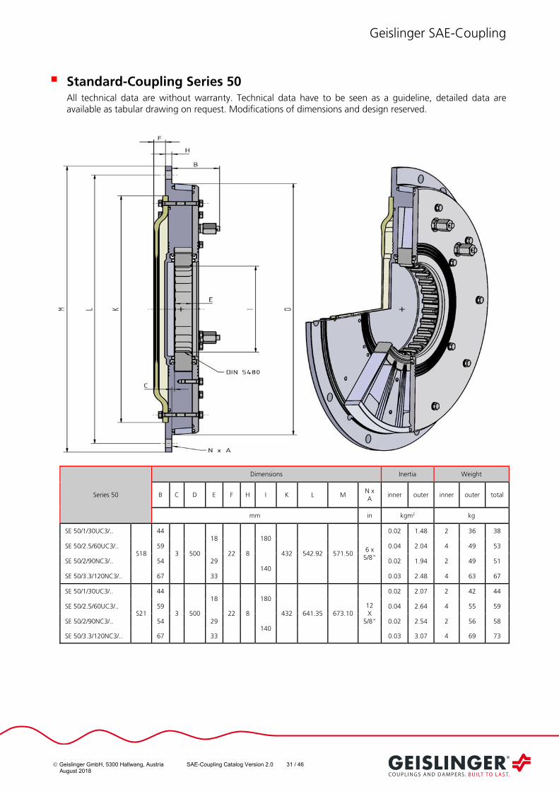
Geislinger GmbH, 5300 Hallwang, Austria SAE-Coupling Catalog Version 2.0 31 / 46 August 2018
Standard-Coupling Series 50 All technical data are without warranty. Technical data have to be seen as a guideline, detailed data are available as tabular drawing on request. Modifications of dimensions and design reserved.
Series 50
Dimensions Inertia Weight
B C D E F H I K L M N x A
inner outer inner outer total
mm in kgm2 kg
SE 50/1/30UC3/..
S18
44
3 500
18
22 8
180
432 542.92 571.50 6 x
5/8"
0.02 1.48 2 36 38
SE 50/2.5/60UC3/.. 59 0.04 2.04 4 49 53
SE 50/2/90NC3/.. 54 29 140
0.02 1.94 2 49 51
SE 50/3.3/120NC3/.. 67 33 0.03 2.48 4 63 67
SE 50/1/30UC3/..
S21
44
3 500
18
22 8
180
432 641.35 673.10 12 X
5/8"
0.02 2.07 2 42 44
SE 50/2.5/60UC3/.. 59 0.04 2.64 4 55 59
SE 50/2/90NC3/.. 54 29 140
0.02 2.54 2 56 58
SE 50/3.3/120NC3/.. 67 33 0.03 3.07 4 69 73
Geislinger SAE-Coupling
Geislinger GmbH, 5300 Hallwang, Austria SAE-Coupling Catalog Version 2.0 32 / 46 August 2018
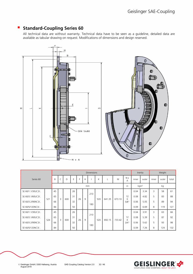
Standard-Coupling Series 60 All technical data are without warranty. Technical data have to be seen as a guideline, detailed data are available as tabular drawing on request. Modifications of dimensions and design reserved.
Series 60
Dimensions Inertia Weight
B C D E F H I K L M N x A
inner outer inner outer total
mm in kgm2 kg
SE 60/1.1/30UC3/..
S21
45
3 600
26
26 9
210
520 641.35 673.10 12 X
5/8"
0.04 3.34 3 58 61
SE 60/3.1/60UC3/.. 65 31 0.08 4.82 5 83 88
SE 60/3.2/90NC3/.. 66 32 180
0.06 5.05 5 89 94
SE 60/5/120NC3/.. 84 50 0.09 6.69 8 119 127
SE 60/1.1/30UC3/..
S24
45
3 600
26
26 9
210
520 692.15 733.42 12 X
3/4"
0.04 3.91 3 63 66
SE 60/3.1/60UC3/.. 65 31 0.08 5.39 5 87 92
SE 60/3.2/90NC3/.. 66 32 180
0.06 5.62 5 93 98
SE 60/5/120NC3/.. 84 50 0.09 7.26 8 124 132
Geislinger SAE-Coupling
Geislinger GmbH, 5300 Hallwang, Austria SAE-Coupling Catalog Version 2.0 33 / 46 August 2018
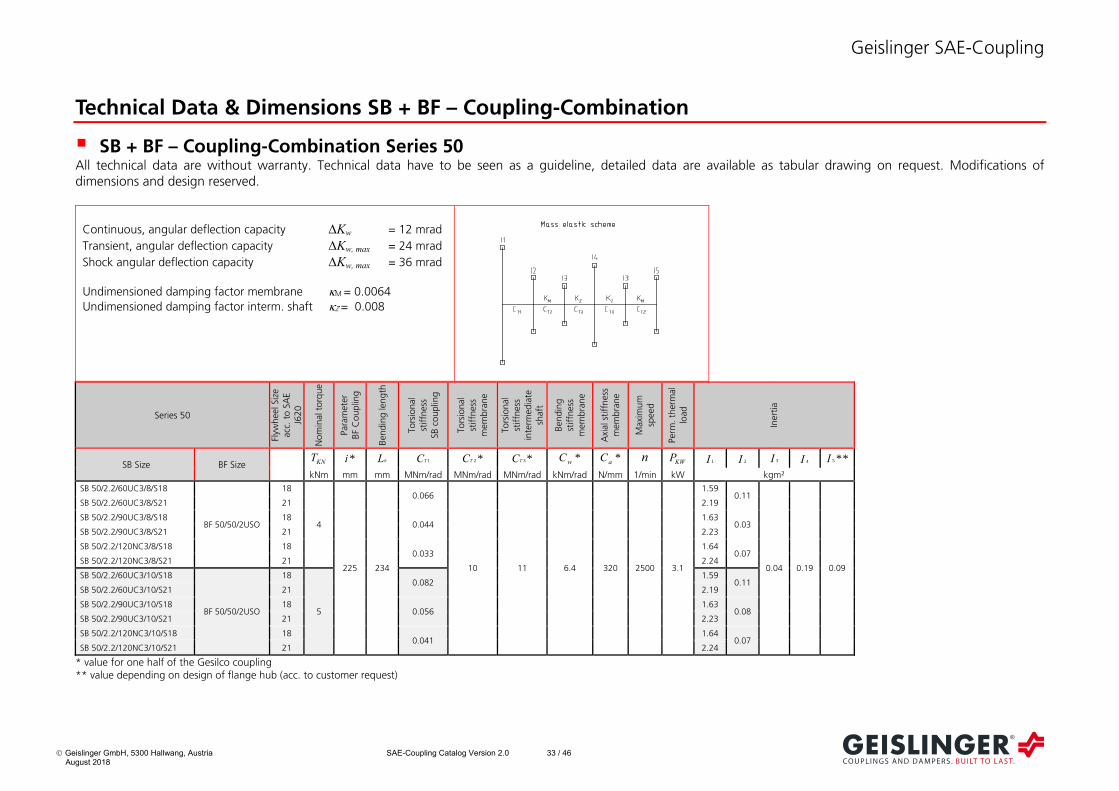
Technical Data & Dimensions SB + BF – Coupling-Combination
SB + BF – Coupling-Combination Series 50 All technical data are without warranty. Technical data have to be seen as a guideline, detailed data are available as tabular drawing on request. Modifications of dimensions and design reserved.
Series 50
Flyw
heel S
ize
acc
. to
SA
E
J620
Nom
inal
torq
ue
Para
mete
r
B
F C
oup
ling
Ben
din
g le
ng
th
To
rsio
nal
stiffn
ess
SB
couplin
g
To
rsio
nal
stiffn
ess
mem
bra
ne
To
rsio
nal
stiffn
ess
inte
rmed
iate
sh
aft
Ben
din
g
stiffn
ess
mem
bra
ne
Axi
al st
iffn
ess
m
em
bra
ne
Maxi
mu
m
spee
d
Perm
. th
erm
al
load
Iner
tia
SB Size BF Size KNT *i bL 1TC *2TC *3TC *wC *aC n
KWP 1I 2I 3I 4I **5I
kNm mm mm MNm/rad MNm/rad MNm/rad kNm/rad N/mm 1/min kW kgm²
SB 50/2.2/60UC3/8/S18
BF 50/50/2USO
18
4
225 234
0.066
10 11 6.4 320 2500 3.1
1.59 0.11
0.04 0.19 0.09
SB 50/2.2/60UC3/8/S21 21 2.19
SB 50/2.2/90UC3/8/S18 18 0.044
1.63 0.03
SB 50/2.2/90UC3/8/S21 21 2.23
SB 50/2.2/120NC3/8/S18 18 0.033
1.64 0.07
SB 50/2.2/120NC3/8/S21 21 2.24
SB 50/2.2/60UC3/10/S18
BF 50/50/2USO
18
5
0.082 1.59
0.11 SB 50/2.2/60UC3/10/S21 21 2.19
SB 50/2.2/90UC3/10/S18 18 0.056
1.63 0.08
SB 50/2.2/90UC3/10/S21 21 2.23
SB 50/2.2/120NC3/10/S18 18 0.041
1.64 0.07
SB 50/2.2/120NC3/10/S21 21 2.24
* value for one half of the Gesilco coupling ** value depending on design of flange hub (acc. to customer request)
Continuous, angular deflection capacity Kw = 12 mrad
Transient, angular deflection capacity Kw, max = 24 mrad
Shock angular deflection capacity Kw, max = 36 mrad
Undimensioned damping factor membrane M = 0.0064
Undimensioned damping factor interm. shaft Z = 0.008
Geislinger SAE-Coupling
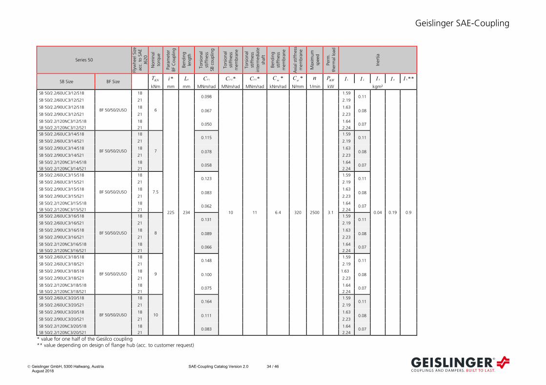
Geislinger GmbH, 5300 Hallwang, Austria SAE-Coupling Catalog Version 2.0 34 / 46 August 2018
Series 50
Flyw
heel S
ize
acc
. to
SA
E
J620
Nom
inal
to
rque
Para
mete
r
BF
Co
up
ling
Ben
din
g
len
gth
To
rsio
nal
stiffn
ess
SB c
ouplin
g
To
rsio
nal
stiffn
ess
mem
bra
ne
To
rsio
nal
stiffn
ess
inte
rmed
iate
sh
aft
Ben
din
g
stiffn
ess
mem
bra
ne
Axi
al st
iffn
ess
m
em
bra
ne
Maxi
mu
m
spee
d
Perm
. th
erm
al lo
ad
Iner
tia
SB Size BF Size KNT *i bL 1TC *2TC *3TC *wC *aC n
KWP 1I 2I 3I 4I **5I
kNm mm mm MNm/rad MNm/rad MNm/rad kNm/rad N/mm 1/min kW kgm²
SB 50/2.2/60UC3/12/S18
BF 50/50/2USO
18
6
225 234
0.098
10 11 6.4 320 2500 3.1
1.59 0.11
0.04 0.19 0.9
SB 50/2.2/60UC3/12/S21 21 2.19
SB 50/2.2/90UC3/12/S18 18 0.067
1.63 0.08
SB 50/2.2/90UC3/12/S21 21 2.23
SB 50/2.2/120NC3/12/S18 18 0.050
1.64 0.07
SB 50/2.2/120NC3/12/S21 21 2.24
SB 50/2.2/60UC3/14/S18
BF 50/50/2USO
18
7
0.115 1.59
0.11 SB 50/2.2/60UC3/14/S21 21 2.19
SB 50/2.2/90UC3/14/S18 18 0.078
1.63 0.08
SB 50/2.2/90UC3/14/S21 21 2.23
SB 50/2.2/120NC3/14/S18 18 0.058
1.64 0.07
SB 50/2.2/120NC3/14/S21 21 2.24
SB 50/2.2/60UC3/15/S18
BF 50/50/2USO
18
7.5
0.123 1.59
0.11 SB 50/2.2/60UC3/15/S21 21 2.19
SB 50/2.2/90UC3/15/S18 18 0.083
1.63 0.08
SB 50/2.2/90UC3/15/S21 21 2.23
SB 50/2.2/120NC3/15/S18 18 0.062
1.64 0.07
SB 50/2.2/120NC3/15/S21 21 2.24
SB 50/2.2/60UC3/16/S18
BF 50/50/2USO
18
8
0.131 1.59
0.11 SB 50/2.2/60UC3/16/S21 21 2.19
SB 50/2.2/90UC3/16/S18 18 0.089
1.63 0.08
SB 50/2.2/90UC3/16/S21 21 2.23
SB 50/2.2/120NC3/16/S18 18 0.066
1.64 0.07
SB 50/2.2/120NC3/16/S21 21 2.24
SB 50/2.2/60UC3/18/S18
BF 50/50/2USO
18
9
0.148 1.59
0.11 SB 50/2.2/60UC3/18/S21 21 2.19
SB 50/2.2/90UC3/18/S18 18 0.100
1.63 0.08
SB 50/2.2/90UC3/18/S21 21 2.23
SB 50/2.2/120NC3/18/S18 18 0.075
1.64 0.07
SB 50/2.2/120NC3/18/S21 21 2.24
SB 50/2.2/60UC3/20/S18
BF 50/50/2USO
18
10
0.164 1.59
0.11 SB 50/2.2/60UC3/20/S21 21 2.19
SB 50/2.2/90UC3/20/S18 18 0.111
1.63 0.08
SB 50/2.2/90UC3/20/S21 21 2.23
SB 50/2.2/120NC3/20/S18 18 0.083
1.64 0.07
SB 50/2.2/120NC3/20/S21 21 2.24
* value for one half of the Gesilco coupling ** value depending on design of flange hub (acc. to customer request)

Geislinger SAE-Coupling
Geislinger GmbH, 5300 Hallwang, Austria SAE-Coupling Catalog Version 2.0 35 / 46 August 2018
** value depending on design of flange hub (acc. to customer request)
Series 50
Dimensions Weight
B C D E F H I K L M N x A
O P R S outer
SB inner
SB BF
Flange Hub**
total**
SB Size BF Size mm in mm kg
SB 50/2.2/60UC3/…
S18 BF 50/50/2USO 24.5 34 500 294 25 8 250 496 542.92 571.50 6x
5/8” 252 max.120 92 154
40.7 10.1
9.5 12.6
72.9
SB 50/2.2/90UC3/... 42.6 7.6 72.3
SB 50/2.2/120NC3/… 43.4 6.8 72.3
SB 50/2.2/60UC3/…
S21 BF 50/50/2USO 24.5 34 500 294 25 8 250 496 641.35 673.10 12x 5/8”
252 max.120 92 154
46.9 10.1
9.5 12.6
79.1
SB 50/2.2/90UC3/... 48.8 7.6 78.5
SB 50/2.2/120NC3/… 49.6 6.8 78.5

Geislinger SAE-Coupling
Geislinger GmbH, 5300 Hallwang, Austria SAE-Coupling Catalog Version 2.0 36 / 46 August 2018
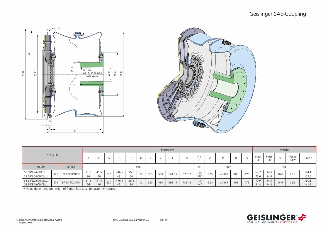
SB + BF – Coupling-Combination Series 58 All technical data are without warranty. Technical data have to be seen as a guideline, detailed data are available as tabular drawing on request. Modifications of dimensions and design reserved.
Continuous, angular deflection capacity Kw = 12 mrad
Transient, angular deflection capacity Kw, max = 24 mrad
Shock angular deflection capacity Kw, max = 36 mrad
Undimensioned damping factor membrane M = 0.0064
Undimensioned damping factor interm. shaft Z = 0.008
Series 58
Flyw
heel S
ize
acc
. to
SA
E
J620
Nom
inal
to
rque
Para
mete
r
BF
Co
up
ling
Ben
din
g le
ng
th
To
rsio
nal
stiffn
ess
SB c
ouplin
g
To
rsio
nal
stiffn
ess
mem
bra
ne
To
rsio
nal
stiffn
ess
inte
rmed
iate
sh
aft
Ben
din
g
stiffn
ess
mem
bra
ne
Axi
al st
iffn
ess
m
em
bra
ne
Maxi
mu
m
spee
d
Perm
. th
erm
al
load
Iner
tia
SB Size BF Size KNT *i bL 1TC *2TC *3TC *wC *aC n
KWP 1I 2I 3I 4I **5I
kNm mm mm MNm/rad MNm/rad MNm/rad kNm/rad N/mm 1/min kW kgm²
SB 58/2.2/60UC3/8/S21
BF 63/50/2USO
21
8
283.5 347
0.133
20 22 12.2 304 2000
4.2 3.52
0.23
0.13 0.65 0.27
SB 58/2.2/60UC3/8/S24 24 4.28
SB 58/3.1/90NC3/8/S21 21 0.088 4.3
4.13 0.24
SB 58/3.1/90NC3/8/S24 24 4.89
SB 58/2.2/60UC3/10/S21
BF 63/50/2USO
21
10
0.167 4.2 3.52
0.23 SB 58/2.2/60UC3/10/S24 24 4.28
SB 58/3.1/90NC3/10/S21 21 0.110 4.3
4.13 0.24
SB 58/3.1/90NC3/10/S24 24 4.89
SB 58/2.2/60UC3/12/S21
BF 63/50/2USO
21
12
0.200 4.2 3.52
0.23 SB 58/2.2/60UC3/12/S24 24 4.28
SB 58/3.1/90NC3/12/S21 21 0.132 4.3
4.13 0.24
SB 58/3.1/90NC3/12/S24 24 4.89
* value for one half of the Gesilco coupling ** value depending on design of flange hub (acc. to customer request)

Geislinger SAE-Coupling
Geislinger GmbH, 5300 Hallwang, Austria SAE-Coupling Catalog Version 2.0 37 / 46 August 2018
Series 58
Flyw
heel S
ize
acc
. to
SA
E
J620
Nom
inal
torq
ue
Para
mete
r
B
F C
oup
ling
Ben
din
g le
ng
th
To
rsio
nal
stiffn
ess
SB
couplin
g
To
rsio
nal
stiffn
ess
mem
bra
ne
To
rsio
nal
stiffn
ess
inte
rmed
iate
sh
aft
Ben
din
g
stiffn
ess
mem
bra
ne
Axi
al st
iffn
ess
m
em
bra
ne
Maxi
mu
m
spee
d
Perm
. th
erm
al
load
Iner
tia
SB Size BF Size KNT *i bL 1TC *2TC *3TC *wC *aC n
KWP 1I 2I 3I 4I **5I
kNm mm mm MNm/rad MNm/rad MNm/rad kNm/rad N/mm 1/min kW kgm²
SB 58/2.2/60UC3/14/S21
BF 63/50/2USO
21
14
283.5 347
0.233
20 22 12.2 304 2000
4.2 3.52
0.23
0.13 0.65 0.27
SB 58/2.2/60UC3/14/S24 24 4.28
SB 58/3.1/90NC3/14/S21 21 0.154 4.3
4.13 0.24
SB 58/3.1/90NC3/14/S24 24 4.89
SB 58/2.2/60UC3/15/S21
BF 63/50/2USO
21
15
0.250 4.2 3.52
0.23 SB 58/2.2/60UC3/15/S24 24 4.28
SB 58/3.1/90NC3/15/S21 21 0.165 4.3
4.13 0.24
SB 58/3.1/90NC3/15/S24 24 4.89
SB 58/2.2/60UC3/16/S21
BF 63/50/2USO
21
16
0.266 4.2 3.52
0.23 SB 58/2.2/60UC3/16/S24 24 4.28
SB 58/3.1/90NC3/16/S21 21 0.176 4.3
4.13 0.24
SB 58/3.1/90NC3/16/S24 24 4.89
SB 58/2.2/60UC3/18/S21
BF 63/50/2USO
21
18
0.300 4.2 3.52
0.23 SB 58/2.2/60UC3/18/S24 24 4.28
SB 58/3.1/90NC3/18/S21 21 0.198 4.3
4.13 0.24
SB 58/3.1/90NC3/18/S24 24 4.89
SB 58/2.2/60UC3/20/S21
BF 63/50/2USO
21
20
0.333 4.2 3.52
0.23 SB 58/2.2/60UC3/20/S24 24 4.28
SB 58/3.1/90NC3/20/S21 21 0.220 4.3
4.13 0.24
SB 58/3.1/90NC3/20/S24 24 4.89
* value for one half of the Gesilco coupling ** value depending on design of flange hub (acc. to customer request)
Geislinger SAE-Coupling
Geislinger GmbH, 5300 Hallwang, Austria SAE-Coupling Catalog Version 2.0 38 / 46 August 2018
** value depending on design of flange hub (acc. to customer request)
Series 58
Dimensions Weight
B C D E F H I K L M N x A
O P R S outer
SB inner
SB BF
Flange Hub**
total**
SB Size BF Size mm in mm kg
SB 58/2.2/60UC3/… S21 BF 63/50/2USO
21.5 41.5 630
416.5 25.5 12 363 580 641.35 673.10
12x 5/8”
320 max.185 105 175 64.7 14.5
18.6 26.3 124.1
SB 58/3.1/90NC3/… 26 46 421 30 75.6 14.8 135.3
SB 58/2.2/60UC3/… S24 BF 63/50/2USO
21.5 41.5 630
416.5 25.5 12 363 580 692.15 733.42
12x 3/4”
320 max.185 105 175 70.9 14.5
18.6 26.3 130.3
SB 58/3.1/90NC3/… 26 46 421 30 81.8 14.8 141.5
Geislinger SAE-Coupling
Geislinger GmbH, 5300 Hallwang, Austria SAE-Coupling Catalog Version 2.0 39 / 46 August 2018
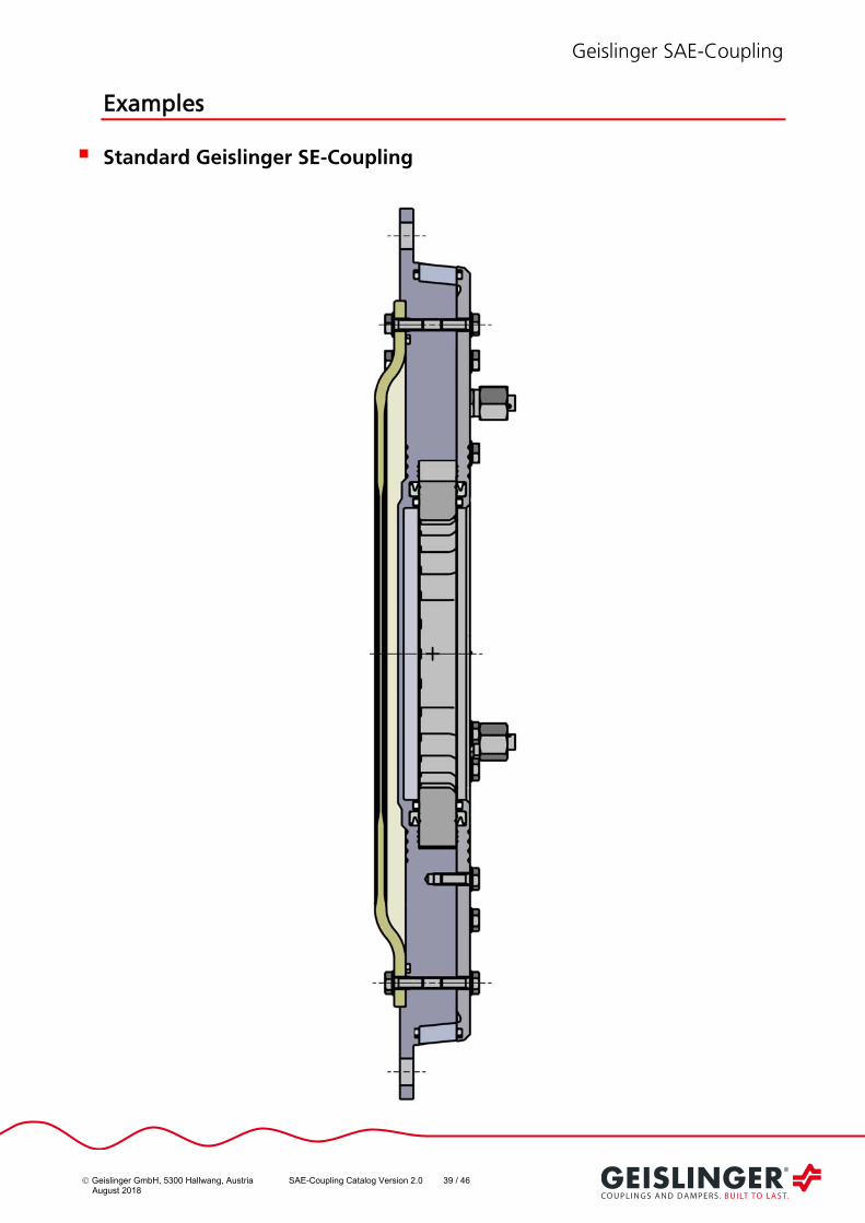
Examples
Standard Geislinger SE-Coupling
Geislinger SAE-Coupling
Geislinger GmbH, 5300 Hallwang, Austria SAE-Coupling Catalog Version 2.0 40 / 46 August 2018
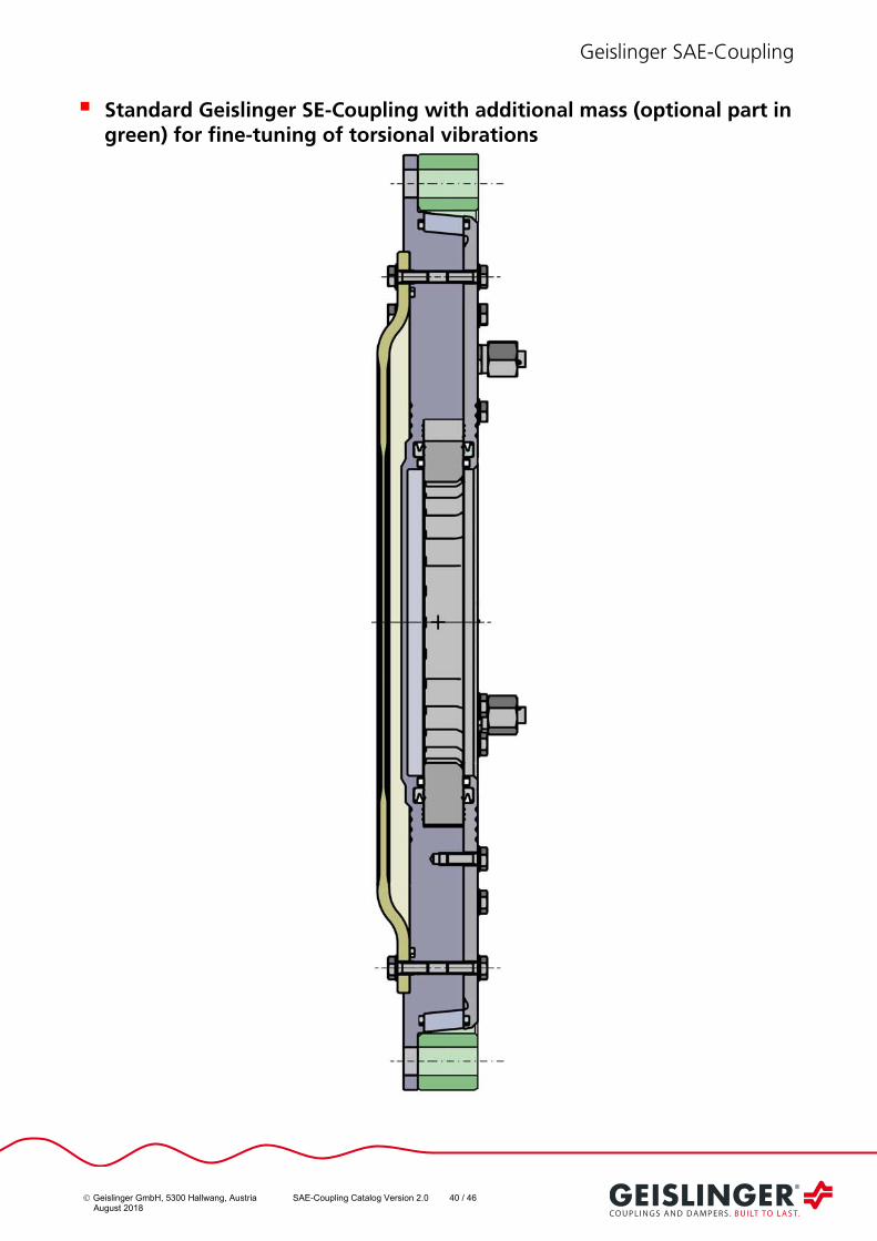
Standard Geislinger SE-Coupling with additional mass (optional part in green) for fine-tuning of torsional vibrations
Geislinger SAE-Coupling
Geislinger GmbH, 5300 Hallwang, Austria SAE-Coupling Catalog Version 2.0 41 / 46 August 2018
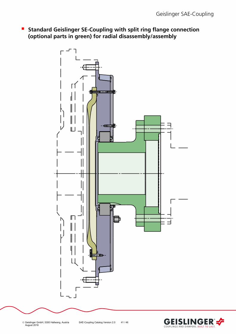
Standard Geislinger SE-Coupling with split ring flange connection (optional parts in green) for radial disassembly/assembly
Geislinger SAE-Coupling
Geislinger GmbH, 5300 Hallwang, Austria SAE-Coupling Catalog Version 2.0 42 / 46 August 2018
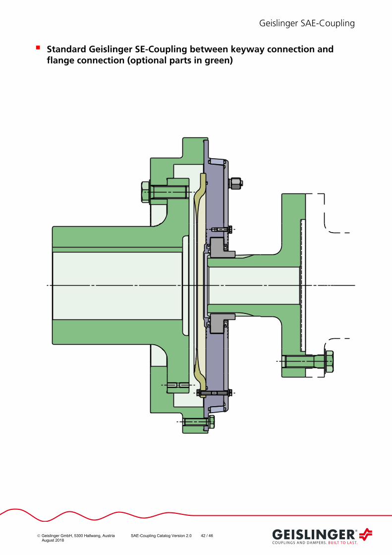
Standard Geislinger SE-Coupling between keyway connection and flange connection (optional parts in green)

Geislinger SAE-Coupling
Geislinger GmbH, 5300 Hallwang, Austria SAE-Coupling Catalog Version 2.0 43 / 46 August 2018
Standard Geislinger SE-Coupling with flange connection (optional part in green)

Geislinger SAE-Coupling
Geislinger GmbH, 5300 Hallwang, Austria SAE-Coupling Catalog Version 2.0 44 / 46 August 2018
Standard Geislinger SE-Coupling with conical connection (optional part in green)

Geislinger SAE-Coupling
Geislinger GmbH, 5300 Hallwang, Austria SAE-Coupling Catalog Version 2.0 45 / 46 August 2018
Standard Geislinger SE-Coupling with conical connection (optional part in green) for flange mounted gearbox

Geislinger SAE-Coupling
Geislinger GmbH, 5300 Hallwang, Austria SAE-Coupling Catalog Version 2.0 46 / 46 August 2018
Standard Geislinger SB + BF – Coupling-Combination with conical flange hub connection (optional part in green)
Geislinger GmbH, Hallwanger Landesstrasse 3, 5300 Hallwang/Salzburg, Austria, Tel. +43 662 669 99-0, Fax +43 662 669 99-40, [email protected]
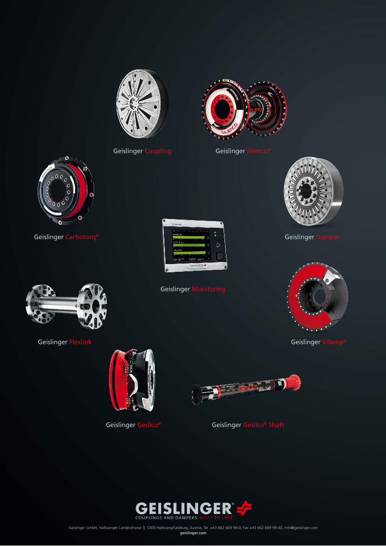
Geislinger Damper
Geislinger Vdamp®Geislinger Flexlink
Geislinger Carbotorq®
Geislinger Gesilco®
Geislinger Monitoring
Geislinger Coupling
Geislinger Gesilco® Shaft
Geislinger Silenco®