coupling the system analysis module to sas4a/sassys-1 · coupling the system analysis module with...
TRANSCRIPT
ANL/NE-16/22 (ANL-ART-74)
Coupling the System Analysis Module with SAS4A/SASSYS-1
Nuclear Engineering Division
About Argonne National Laboratory Argonne is a U.S. Department of Energy laboratory managed by UChicago Argonne, LLC under contract DE-AC02-06CH11357. The Laboratory’s main facility is outside Chicago, at 9700 South Cass Avenue, Argonne, Illinois 60439. For information about Argonne and its pioneering science and technology programs, see www.anl.gov.
DOCUMENT AVAILABILITY
Online Access: U.S. Department of Energy (DOE) reports produced after 1991 and a growing number of pre-1991 documents are available free via DOE’s SciTech Connect (http://www.osti.gov/scitech/)
Reports not in digital format may be purchased by the public from the National Technical Information Service (NTIS):
U.S. Department of Commerce National Technical Information Service 5301 Shawnee Rd Alexandra, VA 22312 www.ntis.gov Phone: (800) 553-NTIS (6847) or (703) 605-6000 Fax: (703) 605-6900 Email: [email protected]
Reports not in digital format are available to DOE and DOE contractors from the Office of Scientific and Technical Information (OSTI):
U.S. Department of Energy Office of Scientific and Technical Information P.O. Box 62 Oak Ridge, TN 37831-0062 www.osti.gov Phone: (865) 576-8401 Fax: (865) 576-5728 Email: [email protected]
Disclaimer This report was prepared as an account of work sponsored by an agency of the United States Government. Neither the United States Government nor any agency thereof, nor UChicago Argonne, LLC, nor any of their employees or officers, makes any warranty, express or implied, or assumes any legal liability or responsibility for the accuracy, completeness, or usefulness of any information, apparatus, product, or process disclosed, or represents that its use would not infringe privately owned rights. Reference herein to any specific commercial product, process, or service by trade name, trademark, manufacturer, or otherwise, does not necessarily constitute or imply its endorsement, recommendation, or favoring by the United States Government or any agency thereof. The views and opinions of document authors expressed herein do not necessarily state or reflect those of the United States Government or any agency thereof, Argonne National Laboratory, or UChicago Argonne, LLC.
ANL/NE-16/22 (ANL-ART-74)
Coupling the System Analysis Module with SAS4A/SASSYS-1
prepared by T. H. Fanning and R. Hu Nuclear Engineering Division, Argonne National Laboratory September 30, 2016

CouplingtheSystemAnalysisModulewithSAS4A/SASSYS-1 September30,2016
i ANL/NE-16/22
ABSTRACT
SAS4A/SASSYS-1isasimulationtoolusedtoperformdeterministicanalysisofanticipatedeventsaswellasdesignbasisandbeyonddesignbasisaccidentsforadvancedreactors,withanemphasisonsodiumfastreactors.SAS4A/SASSYS-1hasbeenunderdevelopmentandinactiveusefornearlyforty-fiveyearsandiscurrentlymaintainedbytheU.S.DepartmentofEnergyundertheOfficeofAdvancedReactorTechnology.AlthoughSAS4A/SASSYS-1containsaverycapableprimaryandintermediatesystemmodelingcomponent,PRIMAR-4,italsohassomeshortcomings:outdateddatamanagementandcodestructuremakesextensionofthePRIMAR-4modulesomewhatdifficult.TheuserinputformatforPRIMAR-4alsolimitsthenumberofvolumesandsegmentsthatcanbeusedtodescribeagivensystem.
TheSystemAnalysisModule(SAM)isafairlynewcodedevelopmenteffortbeingcarriedoutundertheU.S.DOENuclearEnergyAdvancedModelingandSimulation(NEAMS)program.SAMisbeingdevelopedwithadvancedphysicalmodels,numericalmethods,andsoftwareengineeringpractices,howeveritiscurrentlysomewhatlimitedinthesystemcomponentsandphenomenathatcanberepresented.Forexample,componentmodelsforelectromagneticpumpsandmulti-layerstratifiedvolumeshavenotyetbeendeveloped.Noristheresupportforabalanceofplantmodel.Similarly,system-levelphenomenasuchascontrol-roddrivelineexpansionandvesselelongationarenotrepresented.
Thisreportdocumentsfiscalyear2016workthatwascarriedouttocouplethetransientsafetyanalysiscapabilitiesofSAS4A/SASSYS-1withthesystemmodelingcapabilitiesofSAMunderthejointsupportoftheARTandNEAMSprograms.ThecouplingeffortwassuccessfulandisdemonstratedbyevaluatinganunprotectedlossofflowtransientfortheAdvancedBurnerTestReactor(ABTR)design.Therearedifferencesbetweenthestand-aloneSAS4A/SASSYS-1simulationsandthecoupledSAS/SAMsimulations,butthesearemainlyattributedtothelimitedmaturityoftheSAMdevelopmenteffort.
ThesevereaccidentmodelingcapabilitiesinSAS4A/SASSYS-1(sodiumboiling,fuelmeltingandrelocation)willcontinuetoplayavitalroleforalongtime.Therefore,theSAS4A/SASSYS-1modernizationeffortshouldremainahighprioritytaskundertheARTprogramtoensurecontinuedparticipationindomesticandinternationalSFRsafetycollaborationsanddesignoptimizations.Ontheotherhand,SAMprovidesanadvancedsystemanalysistool,withimprovednumericalsolutionschemes,datamanagement,codeflexibility,andaccuracy.SAMisstillinearlystagesofdevelopmentandwillrequirecontinuedsupportfromNEAMStofulfillitspotentialandtomatureintoaproductiontoolforadvancedreactorsafetyanalysis.TheefforttocoupleSAS4A/SASSYS-1andSAMisthefirststepontheintegrationofthesemodelingcapabilities.

CouplingtheSystemAnalysisModulewithSAS4A/SASSYS-1September30,2016
ANL/NE-16/22 ii
CouplingtheSystemAnalysisModulewithSAS4A/SASSYS-1 September30,2016
iii ANL/NE-16/22
TABLEOFCONTENTS
Abstract....................................................................................................................................................................iTableofContents................................................................................................................................................iiiListofFigures.......................................................................................................................................................ivListofTables........................................................................................................................................................iv1 Introduction...................................................................................................................................................52 SAS/SAMCoupling......................................................................................................................................6
2.1 Strategy.................................................................................................................................................62.2 DataExchangeRequirements.....................................................................................................8
3 CodeModifications......................................................................................................................................93.1 SASCodeModifications..................................................................................................................93.2 SAMCodeModifications.............................................................................................................13
4 CouplingResults........................................................................................................................................174.1 ABTRReferenceModel...............................................................................................................174.2 SAMSystemModel........................................................................................................................224.3 VerificationofCouplingInterface...........................................................................................234.4 UnprotectedLossofFlowTransientSequence................................................................254.5 TransientSimulationResultsofUnprotectedLossofFlow........................................25
5 PathForward..............................................................................................................................................326 References....................................................................................................................................................33
CouplingtheSystemAnalysisModulewithSAS4A/SASSYS-1September30,2016
ANL/NE-16/22 iv
LISTOFFIGURES
Figure1:TightCouplingSchemeforaGenericTimeStep................................................................7Figure 2:SAS4A/SASSYS Time Step Hierarchy........................................................................................7Figure3:SequentialTwo-WayCouplingSchemeduringaTransient..........................................8Figure4:RelationshipbetweenPRIMAR-4andtheSAS4A/SASSYS-1
Thermal-HydraulicsSolvers....................................................................................................10Figure5:SummaryofSAS4A/SASSYS-1InputRequiredforSAS/SAM
Coupling...........................................................................................................................................12Figure6:ExampleofSAStoSAM.datfileforSAS/SAMCoupling..................................................15Figure7:ExampleofSAMtoSAS.datfileforSAS/SAMCoupling..................................................16Figure8:ExecutionProcessFlowChartofCoupledSASSteadyExecutioner.........................16Figure9:ExecutionProcessFlowChartofCoupledSASTransientExecutioner....................17Figure10:ReferenceABTRCoreConfiguration.................................................................................18Figure11:ChannelAssignmentsfortheSAS4A/SASSYS-1CoreModel..................................19Figure12:ElevationviewoftheABTRPrimarySystem.................................................................20Figure13:PRIMAR-4RepresentationofthePrimary,Intermediate,and
DecayHeatCoolantSystems...................................................................................................21Figure14:SchematicsoftheABTRmodelforcoupledSAS/SAMsimulations.....................23Figure15:CoupledSAS/SAMsimulationresultsofABTRnulltransient................................24Figure16:NormalizedpowerandcoreflowduringtheABTRULOFtransient...................27Figure17:Pooltemperaturesduringthetransient..........................................................................27Figure18:TransienttemperaturesforChannel5.............................................................................28Figure19:Corechannelflowvelocitiesduringthetransient.......................................................28Figure20:TotalcoreflowdifferencesbetweenSAMsurrogatemodeland
SAS4A/SASSYS-1corechannelsimulationresults........................................................29Figure21:Transientreactivityfeedback...............................................................................................29Figure22:Normalizedpowerandcoreflow,comparisonbetweenstand-
aloneSASandcoupledSAS/SAMsimulationresults....................................................31Figure23:TransienttemperaturesforChannel5,stand-aloneSASsimulation..................31Figure24:Transientreactivityfeedback,stand-aloneSASsimulation....................................32
LISTOFTABLES
Table1:DataexchangeflowforSAS/SAMcouplingatthecouplinginterface........................9
CouplingtheSystemAnalysisModulewithSAS4A/SASSYS-1 September30,2016
5 ANL/NE-16/22
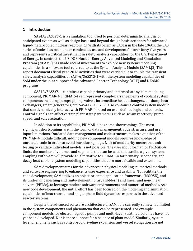
1 IntroductionSAS4A/SASSYS-1isasimulationtoolusedtoperformdeterministicanalysisof
anticipatedeventsaswellasdesignbasisandbeyonddesignbasisaccidentsforadvancedliquid-metal-coolednuclearreactors.[1]WithitsoriginasSAS1Ainthelate1960s,theSASseriesofcodeshasbeenundercontinuoususeanddevelopmentforoverforty-fiveyearsandrepresentsacriticalinvestmentinsafetyanalysiscapabilitiesfortheU.S.DepartmentofEnergy.Incontrast,theUSDOENuclearEnergyAdvancedModelingandSimulationProgram(NEAMS)hasmaderecentinvestmentstoexplorenewsystemsmodelingcapabilitiesinasoftwaretoolreferredtoastheSystemAnalysisModule(SAM).[2]Thisreportdocumentsfiscalyear2016activitiesthatwerecarriedouttocouplethetransientsafetyanalysiscapabilitiesofSAS4A/SASSYS-1withthesystemmodelingcapabilitiesofSAMunderthejointsupportoftheAdvancedReactorTechnology(ART)andNEAMSprograms.
SAS4A/SASSYS-1containsacapableprimaryandintermediatesystemmodelingcomponent,PRIMAR-4.PRIMAR-4canrepresentcomplexarrangementsofcoolantsystemcomponentsincludingpumps,piping,valves,intermediateheatexchangers,airdumpheatexchangers,steamgenerators,etc.SAS4A/SASSYS-1alsocontainsacontrolsystemmodulethatcandynamicallyinteractwithPRIMAR-4basedonuser-definedlogicandcontrols.Controlsignalscanaffectcertainplantstateparameterssuchasscramreactivity,pumpspeed,andvalveactuation.
Inadditiontoitscapabilities,PRIMAR-4hassomeshortcomings.Themostsignificantshortcomingsareintheformofdatamanagement,codestructure,anduserinputlimitations.OutdateddatamanagementandcodestructuremakesextensionofthePRIMAR-4moduledifficult.Addingnewcomponentmodelsrequiresknowledgeofunrelatedcodeinordertoavoidintroducingbugs.Lackofmodularitymeansthatunittestingtovalidateindividualmodelsisnotpossible.TheuserinputformatforPRIMAR-4limitsthenumberofvolumesandsegmentsthatcanbeusedtodescribeagivensystem.CouplingwithSAMwillprovideanalternativetoPRIMAR-4forprimary,secondary,anddecayheatcoolantsystemmodelingcapabilitiesthataremoreflexibleandextensible.
SAMdevelopmentaimsfortheadvancesinphysicalmodeling,numericalmethods,andsoftwareengineeringtoenhanceitsuserexperienceandusability.Tofacilitatethecodedevelopment,SAMutilizesanobject-orientedapplicationframework(MOOSE),anditsunderlyingmeshingandfinite-elementlibrary(libMesh)andlinearandnon-linearsolvers(PETSc),toleveragemodernsoftwareenvironmentsandnumericalmethods.Asanewcodedevelopment,theinitialefforthasbeenfocusedonthemodelingandsimulationcapabilitiesofheattransferandsingle-phasefluiddynamicsresponsesintheadvancedreactorsystems.
DespitetheadvancedsoftwarearchitectureofSAM,itiscurrentlysomewhatlimitedinthesystemcomponentsandphenomenathatcanberepresented.Forexample,componentmodelsforelectromagneticpumpsandmulti-layerstratifiedvolumeshavenotyetbeendeveloped.Noristheresupportforabalanceofplantmodel.Similarly,system-levelphenomenasuchascontrol-roddrivelineexpansionandvesselelongationarenot
CouplingtheSystemAnalysisModulewithSAS4A/SASSYS-1September30,2016
ANL/NE-16/22 6
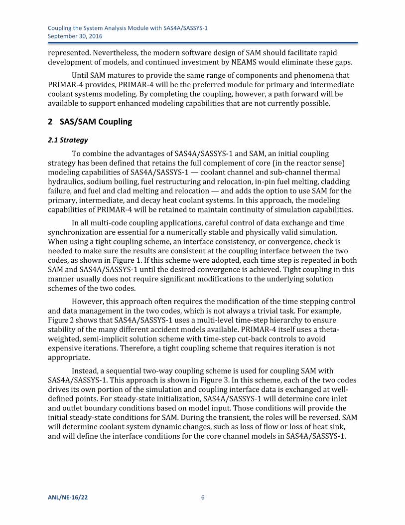
represented.Nevertheless,themodernsoftwaredesignofSAMshouldfacilitaterapiddevelopmentofmodels,andcontinuedinvestmentbyNEAMSwouldeliminatethesegaps.
UntilSAMmaturestoprovidethesamerangeofcomponentsandphenomenathatPRIMAR-4provides,PRIMAR-4willbethepreferredmoduleforprimaryandintermediatecoolantsystemsmodeling.Bycompletingthecoupling,however,apathforwardwillbeavailabletosupportenhancedmodelingcapabilitiesthatarenotcurrentlypossible.
2 SAS/SAMCoupling
2.1 StrategyTocombinetheadvantagesofSAS4A/SASSYS-1andSAM,aninitialcoupling
strategyhasbeendefinedthatretainsthefullcomplementofcore(inthereactorsense)modelingcapabilitiesofSAS4A/SASSYS-1—coolantchannelandsub-channelthermalhydraulics,sodiumboiling,fuelrestructuringandrelocation,in-pinfuelmelting,claddingfailure,andfuelandcladmeltingandrelocation—andaddstheoptiontouseSAMfortheprimary,intermediate,anddecayheatcoolantsystems.Inthisapproach,themodelingcapabilitiesofPRIMAR-4willberetainedtomaintaincontinuityofsimulationcapabilities.
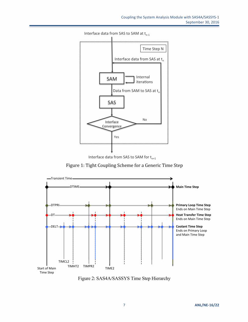
Inallmulti-codecouplingapplications,carefulcontrolofdataexchangeandtimesynchronizationareessentialforanumericallystableandphysicallyvalidsimulation.Whenusingatightcouplingscheme,aninterfaceconsistency,orconvergence,checkisneededtomakesuretheresultsareconsistentatthecouplinginterfacebetweenthetwocodes,asshowninFigure1.Ifthisschemewereadopted,eachtimestepisrepeatedinbothSAMandSAS4A/SASSYS-1untilthedesiredconvergenceisachieved.Tightcouplinginthismannerusuallydoesnotrequiresignificantmodificationstotheunderlyingsolutionschemesofthetwocodes.
However,thisapproachoftenrequiresthemodificationofthetimesteppingcontrolanddatamanagementinthetwocodes,whichisnotalwaysatrivialtask.Forexample,Figure 2showsthatSAS4A/SASSYS-1usesamulti-leveltime-stephierarchytoensurestabilityofthemanydifferentaccidentmodelsavailable.PRIMAR-4itselfusesatheta-weighted,semi-implicitsolutionschemewithtime-stepcut-backcontrolstoavoidexpensiveiterations.Therefore,atightcouplingschemethatrequiresiterationisnotappropriate.
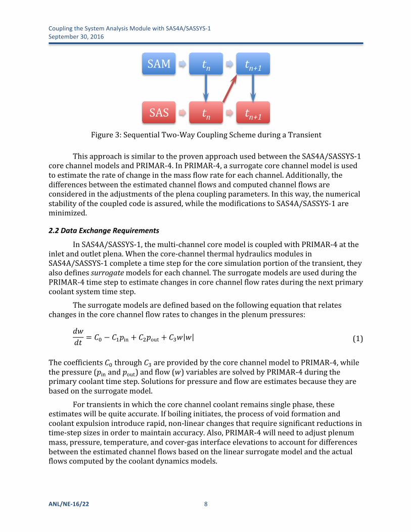
Instead,asequentialtwo-waycouplingschemeisusedforcouplingSAMwithSAS4A/SASSYS-1.ThisapproachisshowninFigure3.Inthisscheme,eachofthetwocodesdrivesitsownportionofthesimulationandcouplinginterfacedataisexchangedatwell-definedpoints.Forsteady-stateinitialization,SAS4A/SASSYS-1willdeterminecoreinletandoutletboundaryconditionsbasedonmodelinput.Thoseconditionswillprovidetheinitialsteady-stateconditionsforSAM.Duringthetransient,theroleswillbereversed.SAMwilldeterminecoolantsystemdynamicchanges,suchaslossoffloworlossofheatsink,andwilldefinetheinterfaceconditionsforthecorechannelmodelsinSAS4A/SASSYS-1.
CouplingtheSystemAnalysisModulewithSAS4A/SASSYS-1 September30,2016
7 ANL/NE-16/22
Figure1:TightCouplingSchemeforaGenericTimeStep
Figure 2:SAS4A/SASSYS Time Step Hierarchy
SAM$
SAS$
Interface$data$from$SAS$to$SAM$at$tn01$
Interface$data$from$SAS$to$SAM$for$tn+1$
Internal$itera5ons$
Time$Step$N$
Interface$Convergence$
Yes$
No$
Data$from$SAM$to$SAS$at$tn$
Interface$data$from$SAS$at$tn$
DELT%
DT%
DTPRI%
DTIME%
Transient%Time%
Start%of%Main%Time%Step%
TIMCL2%TIMHT2% TIMPR2% TIME2%
Main%Time%Step%
Primary%Loop%Time%Step%Ends%on%Main%Time%Step%
Heat%Transfer%Time%Step%Ends%on%Main%Time%Step%
Coolant%Time%Step%Ends%on%Primary%Loop%and%Main%Time%Step%
CouplingtheSystemAnalysisModulewithSAS4A/SASSYS-1September30,2016
ANL/NE-16/22 8
Figure3:SequentialTwo-WayCouplingSchemeduringaTransient
ThisapproachissimilartotheprovenapproachusedbetweentheSAS4A/SASSYS-1corechannelmodelsandPRIMAR-4.InPRIMAR-4,asurrogatecorechannelmodelisusedtoestimatetherateofchangeinthemassflowrateforeachchannel.Additionally,thedifferencesbetweentheestimatedchannelflowsandcomputedchannelflowsareconsideredintheadjustmentsoftheplenacouplingparameters.Inthisway,thenumericalstabilityofthecoupledcodeisassured,whilethemodificationstoSAS4A/SASSYS-1areminimized.
2.2 DataExchangeRequirements
InSAS4A/SASSYS-1,themulti-channelcoremodeliscoupledwithPRIMAR-4attheinletandoutletplena.Whenthecore-channelthermalhydraulicsmodulesinSAS4A/SASSYS-1completeatimestepforthecoresimulationportionofthetransient,theyalsodefinessurrogatemodelsforeachchannel.ThesurrogatemodelsareusedduringthePRIMAR-4timesteptoestimatechangesincorechannelflowratesduringthenextprimarycoolantsystemtimestep.
Thesurrogatemodelsaredefinedbasedonthefollowingequationthatrelateschangesinthecorechannelflowratestochangesintheplenumpressures:
𝑑𝑤𝑑𝑡 = 𝐶! − 𝐶!𝑝in + 𝐶!𝑝out + 𝐶!𝑤 𝑤 (1)
Thecoefficients𝐶!through𝐶!areprovidedbythecorechannelmodeltoPRIMAR-4,whilethepressure(𝑝inand𝑝out)andflow(𝑤)variablesaresolvedbyPRIMAR-4duringtheprimarycoolanttimestep.Solutionsforpressureandflowareestimatesbecausetheyarebasedonthesurrogatemodel.
Fortransientsinwhichthecorechannelcoolantremainssinglephase,theseestimateswillbequiteaccurate.Ifboilinginitiates,theprocessofvoidformationandcoolantexpulsionintroducerapid,non-linearchangesthatrequiresignificantreductionsintime-stepsizesinordertomaintainaccuracy.Also,PRIMAR-4willneedtoadjustplenummass,pressure,temperature,andcover-gasinterfaceelevationstoaccountfordifferencesbetweentheestimatedchannelflowsbasedonthelinearsurrogatemodelandtheactualflowscomputedbythecoolantdynamicsmodels.
! 4!
&Figure 2: Sequential Two-Way Coupling Scheme for a Generic Time Step
This& approach& is& similar& to& the& proven& approach& used& between& the& SAS4A/SASSYSP1&core&channel&models&and&PRIMARP4.&In&PRIMARP4,&a&surrogate&core&channel&model&is&used&to& estimate& the& rate& of& change& in& the&mass& flow& rate& for& each& channel.& Additionally,& the&differences& between& the& estimated& channel& flows& and& computed& channel& flows& are&considered&in&the&adjustments&of&the&plena&coupling¶meters.&In&this&way,&the&numerical&stability& of& the& coupled& code& is& assured,&while& the&modifications& of& SAS4A/SASSYSP1& are&minimized.&
Data*Exchange*Requirements*
In& SAS4A/SASSYSP1,& the& multiPchannel& core& model& is& coupled& with& PRIMARP4& at& the&inlet& and& outlet& plenums.& When& the& corePchannel& thermal& hydraulics& module& in&SAS4A/SASSYSP1&completes&a&time&step&for&the&core&simulation&portion&of&the&transient,&it&also&defines&surrogate&models&for&each&channel.&The&surrogate&models&are&used&during&the&PRIMARP4& time& step& to& approximate& changes& in& core& channel& flow& rates& during& the& next&primary&coolant&system&time&step.&
The&surrogate&models&are&defined&based&on&the&following&equation&that&relates&changes&in&the&core&channel&flow&rates&to&changes&in&the&plenum&pressures:&
!"!" = !! − !!!in + !!!out + !!! ! & (1)&
The&coefficients&!!&through&!!&are&provided&by&the&core&channel&model&to&PRIMARP4,&while&the&pressure&and&flow&variables&are&solved&by&PRIMARP4&during&the&primary&coolant&time&step.&Solutions&for&pressure&and&flow&are&estimates&because&they&are&based&on&the&surrogate&model.&
For&transients&in&which&the&core&channel&coolant&remains&single&phase,&these&estimates&will& be& quite& accurate.& If& boiling& initiates,& the& process& of& void& formation& and& coolant&expulsion& introduce&rapid,&nonPlinear&changes& that&require&significant&reductions& in& timePstep&sizes&in&order&to&maintain&accuracy.&Also,&PRIMARP4&will&need&to&adjust&plenum&mass,&pressure,& temperature,& and& coverPgas& interface& elevations& to& account& for& differences&between&the&estimated&channel& flows&based&on&the& linear&surrogate&model&and&the&actual&flows&computed&by&the&coolant&dynamics&models.&&
SAM& tn* tn+1*
SAS& tn* tn+1*
CouplingtheSystemAnalysisModulewithSAS4A/SASSYS-1 September30,2016
9 ANL/NE-16/22
Followingcompletionofatimestepfortheprimaryandintermediatecoolantloops,PRIMAR-4providesthefollowinginformationbacktothecorechannelcoolantdynamicsroutinesinSAS4A/SASSYS-1:
𝑝in 𝑡! =inletplenumpressureatthebeginningofthePRIMAR-4timestep
𝑝out 𝑡! =outletplenumpressureatthebeginningofthePRIMAR-4timestep
𝑑𝑝in𝑑𝑡 ,
𝑑𝑝out𝑑𝑡 =timederivativesoftheinletandoutletplenumpressures
𝑇in,𝑇out =inletandoutletplenumtemperatures
Theseparametersprovidetheboundaryconditionsneededtoupdatethecorechannelsolution.
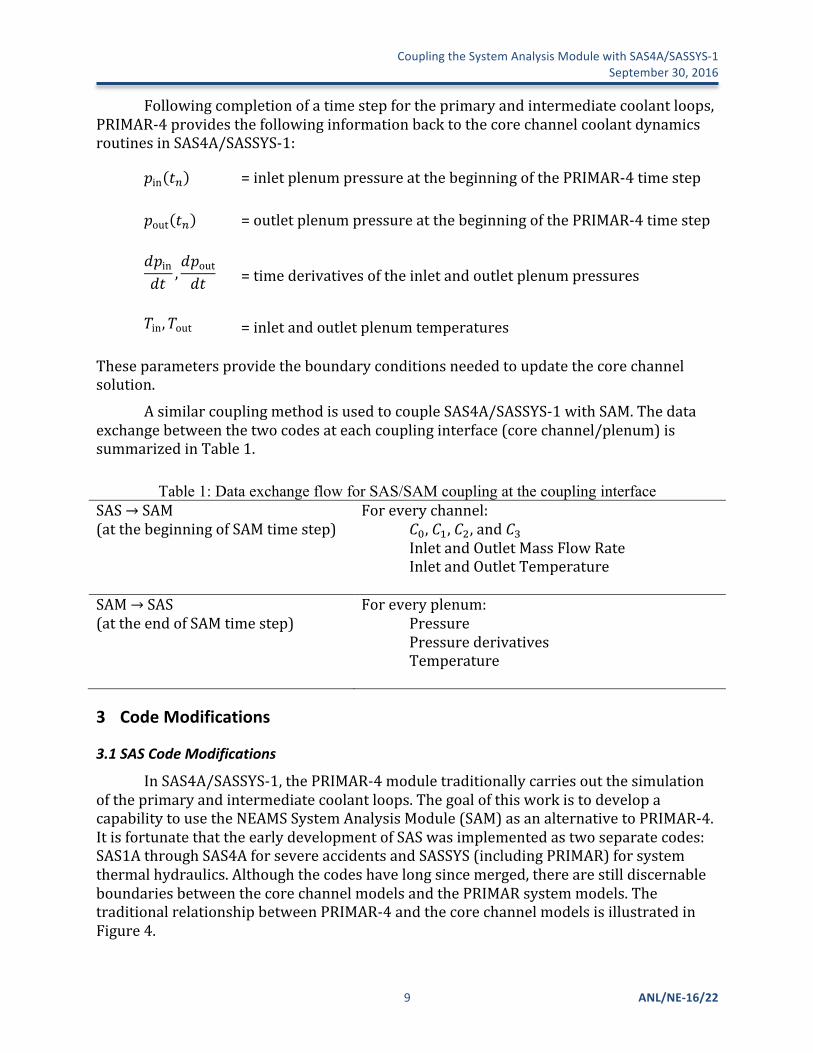
AsimilarcouplingmethodisusedtocoupleSAS4A/SASSYS-1withSAM.Thedataexchangebetweenthetwocodesateachcouplinginterface(corechannel/plenum)issummarizedinTable1.
Table 1: Data exchange flow for SAS/SAM coupling at the coupling interface SAS→SAM(atthebeginningofSAMtimestep)
Foreverychannel: 𝐶!,𝐶!,𝐶!,and𝐶! InletandOutletMassFlowRate InletandOutletTemperature
SAM→SAS(attheendofSAMtimestep)
Foreveryplenum: Pressure Pressurederivatives Temperature
3 CodeModifications
3.1 SASCodeModifications
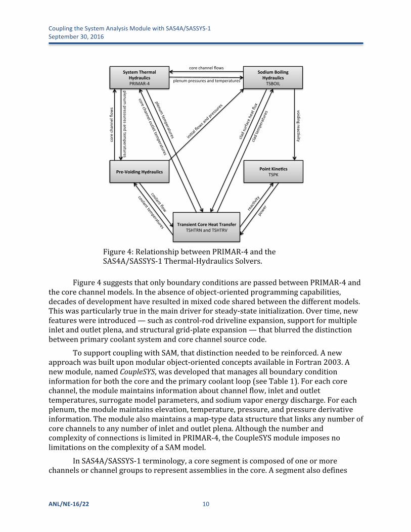
InSAS4A/SASSYS-1,thePRIMAR-4moduletraditionallycarriesoutthesimulationoftheprimaryandintermediatecoolantloops.ThegoalofthisworkistodevelopacapabilitytousetheNEAMSSystemAnalysisModule(SAM)asanalternativetoPRIMAR-4.ItisfortunatethattheearlydevelopmentofSASwasimplementedastwoseparatecodes:SAS1AthroughSAS4AforsevereaccidentsandSASSYS(includingPRIMAR)forsystemthermalhydraulics.Althoughthecodeshavelongsincemerged,therearestilldiscernableboundariesbetweenthecorechannelmodelsandthePRIMARsystemmodels.ThetraditionalrelationshipbetweenPRIMAR-4andthecorechannelmodelsisillustratedinFigure4.
CouplingtheSystemAnalysisModulewithSAS4A/SASSYS-1September30,2016
ANL/NE-16/22 10
Figure4:RelationshipbetweenPRIMAR-4andtheSAS4A/SASSYS-1Thermal-HydraulicsSolvers.
Figure4suggeststhatonlyboundaryconditionsarepassedbetweenPRIMAR-4andthecorechannelmodels.Intheabsenceofobject-orientedprogrammingcapabilities,decadesofdevelopmenthaveresultedinmixedcodesharedbetweenthedifferentmodels.Thiswasparticularlytrueinthemaindriverforsteady-stateinitialization.Overtime,newfeatureswereintroduced—suchascontrol-roddrivelineexpansion,supportformultipleinletandoutletplena,andstructuralgrid-plateexpansion—thatblurredthedistinctionbetweenprimarycoolantsystemandcorechannelsourcecode.
TosupportcouplingwithSAM,thatdistinctionneededtobereinforced.Anewapproachwasbuiltuponmodularobject-orientedconceptsavailableinFortran2003.Anewmodule,namedCoupleSYS,wasdevelopedthatmanagesallboundaryconditioninformationforboththecoreandtheprimarycoolantloop(seeTable1).Foreachcorechannel,themodulemaintainsinformationaboutchannelflow,inletandoutlettemperatures,surrogatemodelparameters,andsodiumvaporenergydischarge.Foreachplenum,themodulemaintainselevation,temperature,pressure,andpressurederivativeinformation.Themodulealsomaintainsamap-typedatastructurethatlinksanynumberofcorechannelstoanynumberofinletandoutletplena.AlthoughthenumberandcomplexityofconnectionsislimitedinPRIMAR-4,theCoupleSYSmoduleimposesnolimitationsonthecomplexityofaSAMmodel.
InSAS4A/SASSYS-1terminology,acoresegmentiscomposedofoneormorechannelsorchannelgroupstorepresentassembliesinthecore.Asegmentalsodefines
SystemThermalHydraulicsPRIMAR-4
Pre-VoidingHydraulics
SodiumBoilingHydraulicsTSBOIL
PointKine:csTSPK
TransientCoreHeatTransferTSHTRNandTSHTRV
corechann
elflow
s
plenumpressuresandtemperatures
corechannelflows
plenumpressuresandtem
peratures
voidingreacEvity
reacEvity
power
iniEalflowsandpressures
coolantflow
coolanttemperatures
cladsurfa
ceheatflux
cladtemperatures
plenumtem
peratures
corechanneloutlettemperatures
CouplingtheSystemAnalysisModulewithSAS4A/SASSYS-1 September30,2016
11 ANL/NE-16/22
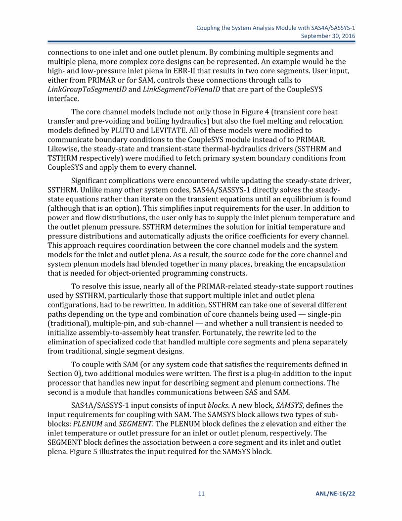
connectionstooneinletandoneoutletplenum.Bycombiningmultiplesegmentsandmultipleplena,morecomplexcoredesignscanberepresented.Anexamplewouldbethehigh-andlow-pressureinletplenainEBR-IIthatresultsintwocoresegments.Userinput,eitherfromPRIMARorforSAM,controlstheseconnectionsthroughcallstoLinkGroupToSegmentIDandLinkSegmentToPlenaIDthatarepartoftheCoupleSYSinterface.
ThecorechannelmodelsincludenotonlythoseinFigure4(transientcoreheattransferandpre-voidingandboilinghydraulics)butalsothefuelmeltingandrelocationmodelsdefinedbyPLUTOandLEVITATE.AllofthesemodelsweremodifiedtocommunicateboundaryconditionstotheCoupleSYSmoduleinsteadoftoPRIMAR.Likewise,thesteady-stateandtransient-statethermal-hydraulicsdrivers(SSTHRMandTSTHRMrespectively)weremodifiedtofetchprimarysystemboundaryconditionsfromCoupleSYSandapplythemtoeverychannel.
Significantcomplicationswereencounteredwhileupdatingthesteady-statedriver,SSTHRM.Unlikemanyothersystemcodes,SAS4A/SASSYS-1directlysolvesthesteady-stateequationsratherthaniterateonthetransientequationsuntilanequilibriumisfound(althoughthatisanoption).Thissimplifiesinputrequirementsfortheuser.Inadditiontopowerandflowdistributions,theuseronlyhastosupplytheinletplenumtemperatureandtheoutletplenumpressure.SSTHRMdeterminesthesolutionforinitialtemperatureandpressuredistributionsandautomaticallyadjuststheorificecoefficientsforeverychannel.Thisapproachrequirescoordinationbetweenthecorechannelmodelsandthesystemmodelsfortheinletandoutletplena.Asaresult,thesourcecodeforthecorechannelandsystemplenummodelshadblendedtogetherinmanyplaces,breakingtheencapsulationthatisneededforobject-orientedprogrammingconstructs.
Toresolvethisissue,nearlyallofthePRIMAR-relatedsteady-statesupportroutinesusedbySSTHRM,particularlythosethatsupportmultipleinletandoutletplenaconfigurations,hadtoberewritten.Inaddition,SSTHRMcantakeoneofseveraldifferentpathsdependingonthetypeandcombinationofcorechannelsbeingused—single-pin(traditional),multiple-pin,andsub-channel—andwhetheranulltransientisneededtoinitializeassembly-to-assemblyheattransfer.Fortunately,therewriteledtotheeliminationofspecializedcodethathandledmultiplecoresegmentsandplenaseparatelyfromtraditional,singlesegmentdesigns.
TocouplewithSAM(oranysystemcodethatsatisfiestherequirementsdefinedinSection0),twoadditionalmoduleswerewritten.Thefirstisaplug-inadditiontotheinputprocessorthathandlesnewinputfordescribingsegmentandplenumconnections.ThesecondisamodulethathandlescommunicationsbetweenSASandSAM.
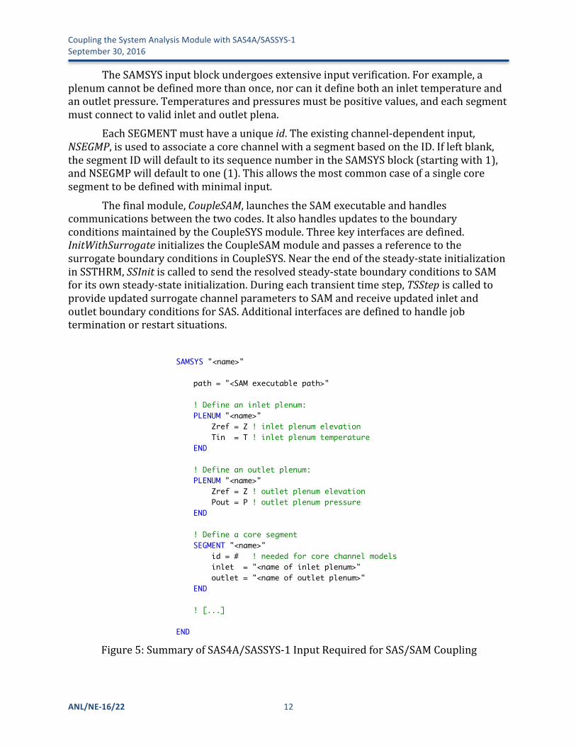
SAS4A/SASSYS-1inputconsistsofinputblocks.Anewblock,SAMSYS,definestheinputrequirementsforcouplingwithSAM.TheSAMSYSblockallowstwotypesofsub-blocks:PLENUMandSEGMENT.ThePLENUMblockdefinesthezelevationandeithertheinlettemperatureoroutletpressureforaninletoroutletplenum,respectively.TheSEGMENTblockdefinestheassociationbetweenacoresegmentanditsinletandoutletplena.Figure5illustratestheinputrequiredfortheSAMSYSblock.
CouplingtheSystemAnalysisModulewithSAS4A/SASSYS-1September30,2016
ANL/NE-16/22 12
TheSAMSYSinputblockundergoesextensiveinputverification.Forexample,aplenumcannotbedefinedmorethanonce,norcanitdefinebothaninlettemperatureandanoutletpressure.Temperaturesandpressuresmustbepositivevalues,andeachsegmentmustconnecttovalidinletandoutletplena.
EachSEGMENTmusthaveauniqueid.Theexistingchannel-dependentinput,NSEGMP,isusedtoassociateacorechannelwithasegmentbasedontheID.Ifleftblank,thesegmentIDwilldefaulttoitssequencenumberintheSAMSYSblock(startingwith1),andNSEGMPwilldefaulttoone(1).Thisallowsthemostcommoncaseofasinglecoresegmenttobedefinedwithminimalinput.
Thefinalmodule,CoupleSAM,launchestheSAMexecutableandhandlescommunicationsbetweenthetwocodes.ItalsohandlesupdatestotheboundaryconditionsmaintainedbytheCoupleSYSmodule.Threekeyinterfacesaredefined.InitWithSurrogateinitializestheCoupleSAMmoduleandpassesareferencetothesurrogateboundaryconditionsinCoupleSYS.Neartheendofthesteady-stateinitializationinSSTHRM,SSInitiscalledtosendtheresolvedsteady-stateboundaryconditionstoSAMforitsownsteady-stateinitialization.Duringeachtransienttimestep,TSStepiscalledtoprovideupdatedsurrogatechannelparameterstoSAMandreceiveupdatedinletandoutletboundaryconditionsforSAS.Additionalinterfacesaredefinedtohandlejobterminationorrestartsituations.
Figure5:SummaryofSAS4A/SASSYS-1InputRequiredforSAS/SAMCoupling
Page 1/1SampleInput.inpSaved: 9/15/16, 10:06:31 PM Printed for: Thomas H. Fanning
SAMSYS "<name>"1
2
path = "<SAM executable path>"3
4
! Define an inlet plenum:5
PLENUM "<name>"6
Zref = Z ! inlet plenum elevation7
Tin = T ! inlet plenum temperature8
END9
10
! Define an outlet plenum:11
PLENUM "<name>"12
Zref = Z ! outlet plenum elevation13
Pout = P ! outlet plenum pressure14
END15
16
! Define a core segment17
SEGMENT "<name>"18
id = # ! needed for core channel models19
inlet = "<name of inlet plenum>"20
outlet = "<name of outlet plenum>"21
END22
23
! [...]24
25
END26
27
28
29
CouplingtheSystemAnalysisModulewithSAS4A/SASSYS-1 September30,2016
13 ANL/NE-16/22
3.2 SAMCodeModifications
SignificantcodeupdateshavebeenmadefortheimplementationoftheSAS/SAMcouplingstrategyanddataexchangediscussedintheaboveSections.Majorcodeupdatesinclude:
• Implementationofsurrogatecore-channelflowmodelsinSAM;
• Developmentofnewcouplingboundarycomponents,CoupledVolumeBranchandCoupledLiquidVolume,includingadditionalphysicsmodelingassociatedwiththenewComponents;
• DataexchangeandfileI/O;
• DevelopmentofCoupledSASSteadyExecutionerandsteady-stateinitialization;
• DevelopmentofCoupledSASTransientExecutioner.Asurrogatemodel,asdescribedinEq.(1),isimplementedinSAMtoapproximate
theSAScorechannelflowratebasedoncoefficientsC!throughC!providedbySAS,andthestatevariablesintheSAMprimaryloop.
NewcomponentsweredevelopedinSAMtomodelavolumewithadditionalmasssourcesorsinks,whichrepresenttheconnectingpipesmodeledintheothercodessuchasSAS4A/SASSYS-1.ThegoverningequationsofmassandenergyconservationfortheCoupledVolumeBranchandCoupledLiquidVolumeComponentsare
−𝑑 𝜌𝑉𝑑𝑡 + 𝜌𝑢𝐴𝑛 !
!
!!!
+ 𝑚coupled
!
!!!
+𝑚!"# = 0(1)
−𝑑 𝜌𝑉ℎ𝑑𝑡 + 𝜌𝑢𝐴ℎ𝑛 !
!
!!!
+ 𝑚coupledℎcoupled
!
!!!
+𝑚!"#ℎ = 0(2)
where𝜌 = density of the volume component
𝑉 = volume of the volume component
𝑡 = time
𝜌𝑢 = mass flux at the connecting nodes
𝑢 = flow velocity at the connecting nodes
𝐴 = flow area of the connecting components
ℎ = fluid enthalpy of the volume component
𝑚coupled = coupled pipe flow rate
ℎcoupled = coupled pipe flow enthalpy.
CouplingtheSystemAnalysisModulewithSAS4A/SASSYS-1September30,2016
ANL/NE-16/22 14
WhencoupledwithSAS4A/SASSYS-1,thecorechannelflowratecalculatedfromthesurrogatemodelwillbeusedas𝑚coupledinthecoupledvolumecomponentmodel.Amassadjustmentterm𝑚!"# isalsoincludedtoaccountforthedifferencesbetweentheSAMsurrogatemodelandtheSAS4A/SASSYS-1corechannelmodelresults.
BecauseSAMisdevelopedinanobject-orientedprograminglanguage,mostofthetermsinthecoupledvolumegoverningequationswereavailablefromthedevelopmentoftheoriginalPBVolumeBranchandPBLiquidVolumecomponents.Onlythenewterms,
m!"#$%&'!!!! and m!"#$%&'h!"#$%&'!
!!! ,areimplementedasnewNodalScalarKernelsinSAM.
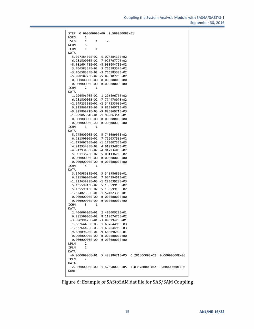
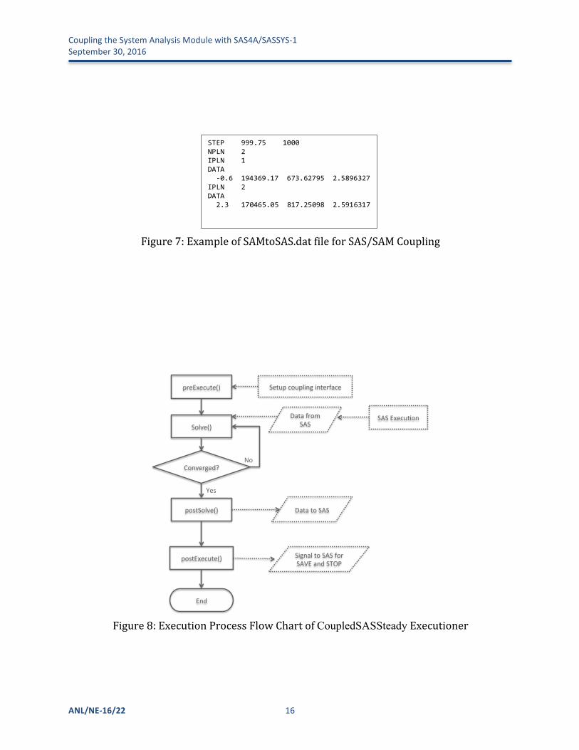
ThedataexchangerequirementsdefinedinSection2.2arecurrentlyimplementedinbothSAS4A/SASSYS-1andSAMthroughfileinputsandoutputs.Directdataexchangethroughmemorycouldbeimplementedinthefuturetoimprovethecouplinginterface.Theexamplesofthedatatransferfiles“SAStoSAM.dat”and“SAMtoSAS.dat”areshowninFigure6andFigure7.Afterthedataisexchanged,itwillbepropagatedintoallrelatedMOOSEobjectsinSAM,includingScalarKernelsandAuxScalarKernelstocalculatethesurrogatecorechannelflowratesandtheflowrateadjustments.
AspecialMOOSEExecutioner,CoupledSASSteady,wasdevelopedtoimplementthecouplingstrategybetweenSAMandSASforsteadystateinitialization.ItinheritsmethodsfromtheregularSteadyExecutioner,butaddssimplifiedmodelsforcouplingboundarycomponentsandadditionalprocessesforcommunicatingwiththeSAScode.ItsprocessflowchartisdepictedinFigure8,wheretheregularprocessesinaSteadyExecutionerareontheleft,andthedashedlinesandblocksontherightareadditionalprocessesforthecoupledcodeexecution.
SpecialmodelingoptionsarealsousedintheCoupledVolumeBranchandCoupledLiquidVolumecomponentsforsteady-stateinitialization.Insteadofusingthesurrogatemodeltocalculatethecorechannelflowrates,constantcorechannelflowratesfromSASareused.Additionally,constantpressureandtemperatureareassumedfortheoutletplenum,whilethepressureandtemperatureoftheinletplenumwillbecalculatedbythecode.Onceaconvergedsimulationisobtained,theinletplenumconditionswillbecheckedwithSASresultsforconsistency.
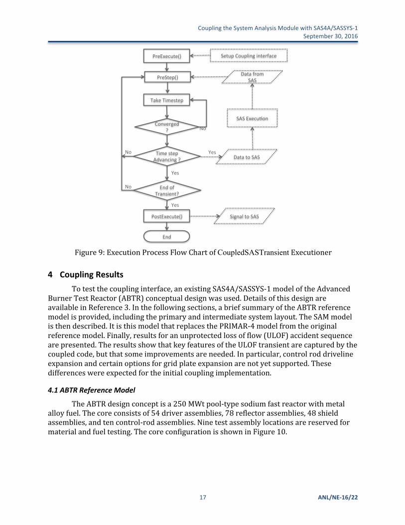
Similarly,atransientExecutioner,CoupledSASTransient,wasdevelopedforcoupledSAM/SAStransientsimulation.ItinheritsmethodsfromtheregularMOOSETransientExecutioner,butaddsadditionalprocessesforcommunicatingwiththeSAScode,asdepictedinFigure9.Ateachtime-step,SAMwillreadintheSASsimulationresults(fromtheprevioustimestep)andcompleteitsowninneriterationsforthetime-step.Itwillalsocheckifthesimulationtimeissynchronizedinthetwocodes.WhentheSAMtimestepisconverged,SAMwillsendtheresultsatthecouplinginterfaces(inletandoutletplenum)toSAS.ThisisthesameprocessasdepictedinFigure3.
CouplingtheSystemAnalysisModulewithSAS4A/SASSYS-1 September30,2016
15 ANL/NE-16/22
Figure6:ExampleofSAStoSAM.datfileforSAS/SAMCoupling
STEP0.00000000E+002.50000000E-01NSEG1ISEG112NCHN5ICHN11DATA5.02738439E+025.02738439E+026.28150000E+027.92070772E+02-8.98160471E+02-8.98160471E+023.76658339E-023.76658339E-02-3.76658339E-02-3.76658339E-02-5.09810775E-02-5.09810775E-020.00000000E+000.00000000E+000.00000000E+000.00000000E+00ICHN21DATA1.29659670E+021.29659670E+026.28150000E+027.77447007E+02-2.34923308E+02-2.34923308E+029.82586971E-039.82586971E-03-9.82586971E-03-9.82586971E-03-1.99906354E-01-1.99906354E-010.00000000E+000.00000000E+000.00000000E+000.00000000E+00ICHN31DATA5.74500990E+025.74500990E+026.28150000E+027.75603758E+02-1.17500736E+03-1.17500736E+034.91293485E-024.91293485E-02-4.91293485E-02-4.91293485E-02-5.09113676E-02-5.09113676E-020.00000000E+000.00000000E+000.00000000E+000.00000000E+00ICHN41DATA3.34098683E+013.34098683E+016.28150000E+027.96439451E+02-1.22363928E+03-1.22363928E+035.13559913E-025.13559913E-02-5.13559913E-02-5.13559913E-02-1.57402335E+01-1.57402335E+010.00000000E+000.00000000E+000.00000000E+000.00000000E+00ICHN51DATA2.40600920E+012.40600920E+016.28150000E+028.11907475E+02-3.89099428E+01-3.89099428E+011.63764495E-031.63764495E-03-1.63764495E-03-1.63764495E-03-9.68009690E-01-9.68009690E-010.00000000E+000.00000000E+000.00000000E+000.00000000E+00NPLN2IPLN1DATA-6.00000000E-015.48818671E+056.28150000E+020.00000000E+00IPLN2DATA2.30000000E+001.62850000E+057.83578000E+020.00000000E+00DONE
CouplingtheSystemAnalysisModulewithSAS4A/SASSYS-1September30,2016
ANL/NE-16/22 16
Figure7:ExampleofSAMtoSAS.datfileforSAS/SAMCoupling
Figure8:ExecutionProcessFlowChartofCoupledSASSteadyExecutioner
preExecute()+
Converged?+
Data+from+SAS+
End+
Solve()+
postSolve()+
postExecute()+
No+
Yes+
Setup+coupling+interface+
Data+to+SAS+
SAS+Execu>on+
Signal+to+SAS+for+SAVE+and+STOP+
STEP999.751000NPLN2IPLN1DATA-0.6194369.17673.627952.5896327IPLN2DATA2.3170465.05817.250982.5916317
CouplingtheSystemAnalysisModulewithSAS4A/SASSYS-1 September30,2016
17 ANL/NE-16/22
Figure9:ExecutionProcessFlowChartofCoupledSASTransientExecutioner
4 CouplingResultsTotestthecouplinginterface,anexistingSAS4A/SASSYS-1modeloftheAdvanced
BurnerTestReactor(ABTR)conceptualdesignwasused.DetailsofthisdesignareavailableinReference3.Inthefollowingsections,abriefsummaryoftheABTRreferencemodelisprovided,includingtheprimaryandintermediatesystemlayout.TheSAMmodelisthendescribed.ItisthismodelthatreplacesthePRIMAR-4modelfromtheoriginalreferencemodel.Finally,resultsforanunprotectedlossofflow(ULOF)accidentsequencearepresented.TheresultsshowthatkeyfeaturesoftheULOFtransientarecapturedbythecoupledcode,butthatsomeimprovementsareneeded.Inparticular,controlroddrivelineexpansionandcertainoptionsforgridplateexpansionarenotyetsupported.Thesedifferenceswereexpectedfortheinitialcouplingimplementation.
4.1 ABTRReferenceModel
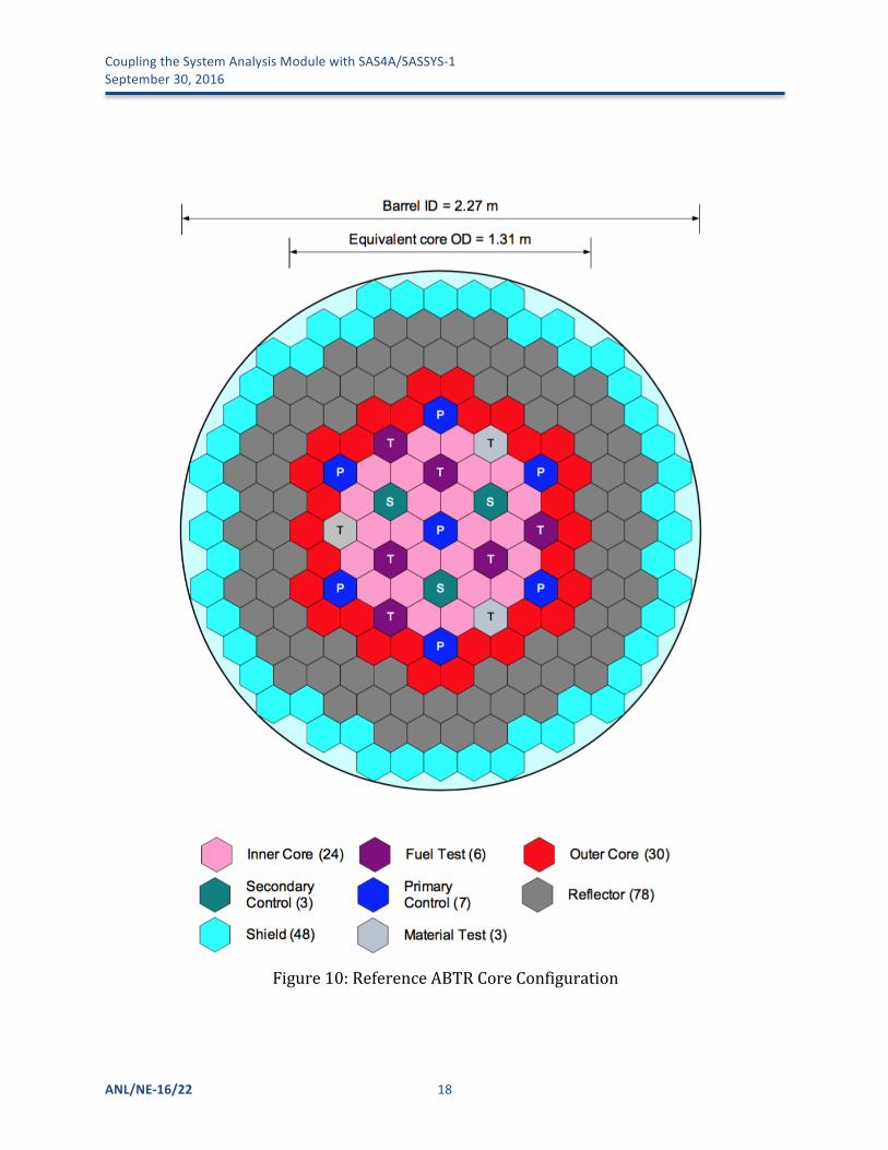
TheABTRdesignconceptisa250MWtpool-typesodiumfastreactorwithmetalalloyfuel.Thecoreconsistsof54driverassemblies,78reflectorassemblies,48shieldassemblies,andtencontrol-rodassemblies.Ninetestassemblylocationsarereservedformaterialandfueltesting.ThecoreconfigurationisshowninFigure10.
PreExecute()+
Converged?+
Data+from+SAS+
End+
Take+Timestep+
PostExecute()+
No+
End+of+Transient?+
Yes+
Yes+
No+
Setup+Coupling+interface+
Data+to+SAS+
SAS+ExecuAon+
Signal+to+SAS+
PreStep()+
Time+step+Advancing+?+
No+
Yes+
CouplingtheSystemAnalysisModulewithSAS4A/SASSYS-1September30,2016
ANL/NE-16/22 18
Figure10:ReferenceABTRCoreConfiguration
CouplingtheSystemAnalysisModulewithSAS4A/SASSYS-1 September30,2016
19 ANL/NE-16/22
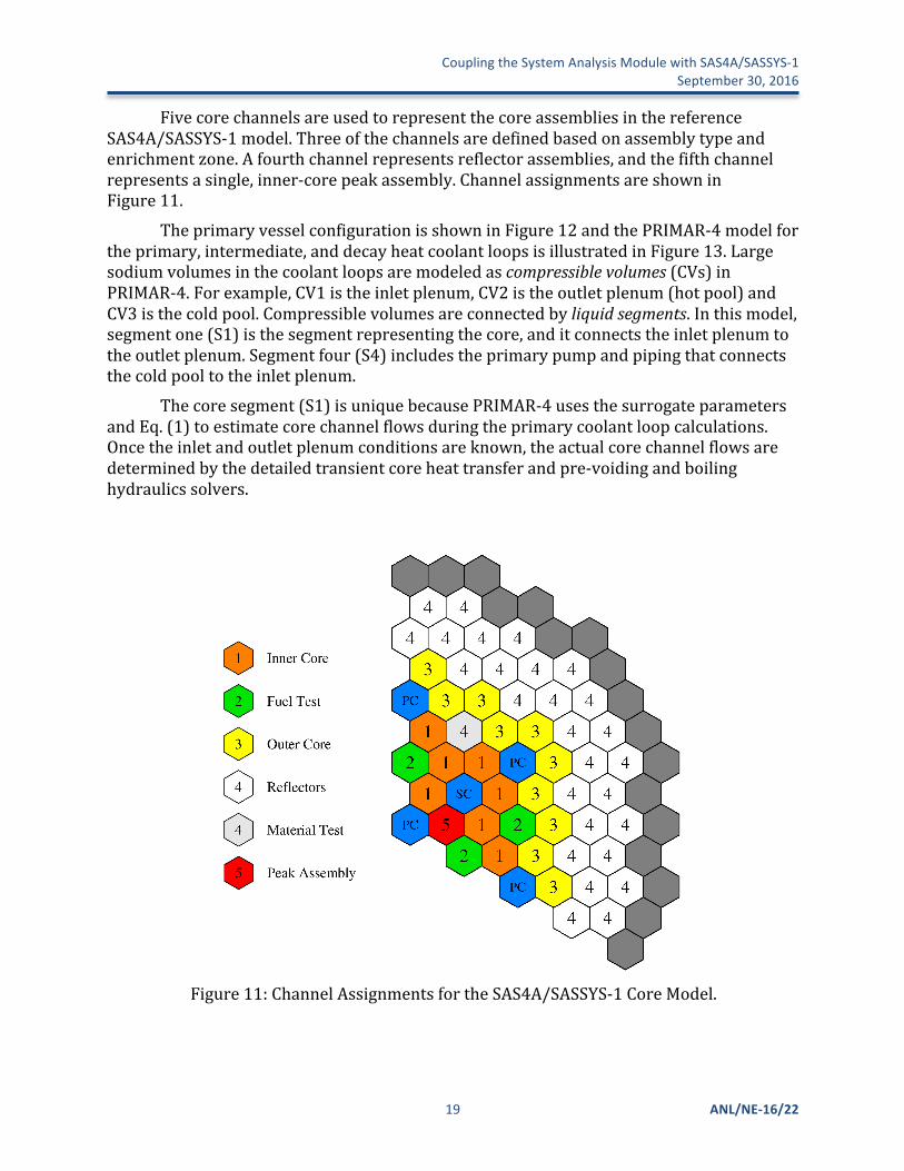
FivecorechannelsareusedtorepresentthecoreassembliesinthereferenceSAS4A/SASSYS-1model.Threeofthechannelsaredefinedbasedonassemblytypeandenrichmentzone.Afourthchannelrepresentsreflectorassemblies,andthefifthchannelrepresentsasingle,inner-corepeakassembly.ChannelassignmentsareshowninFigure11.
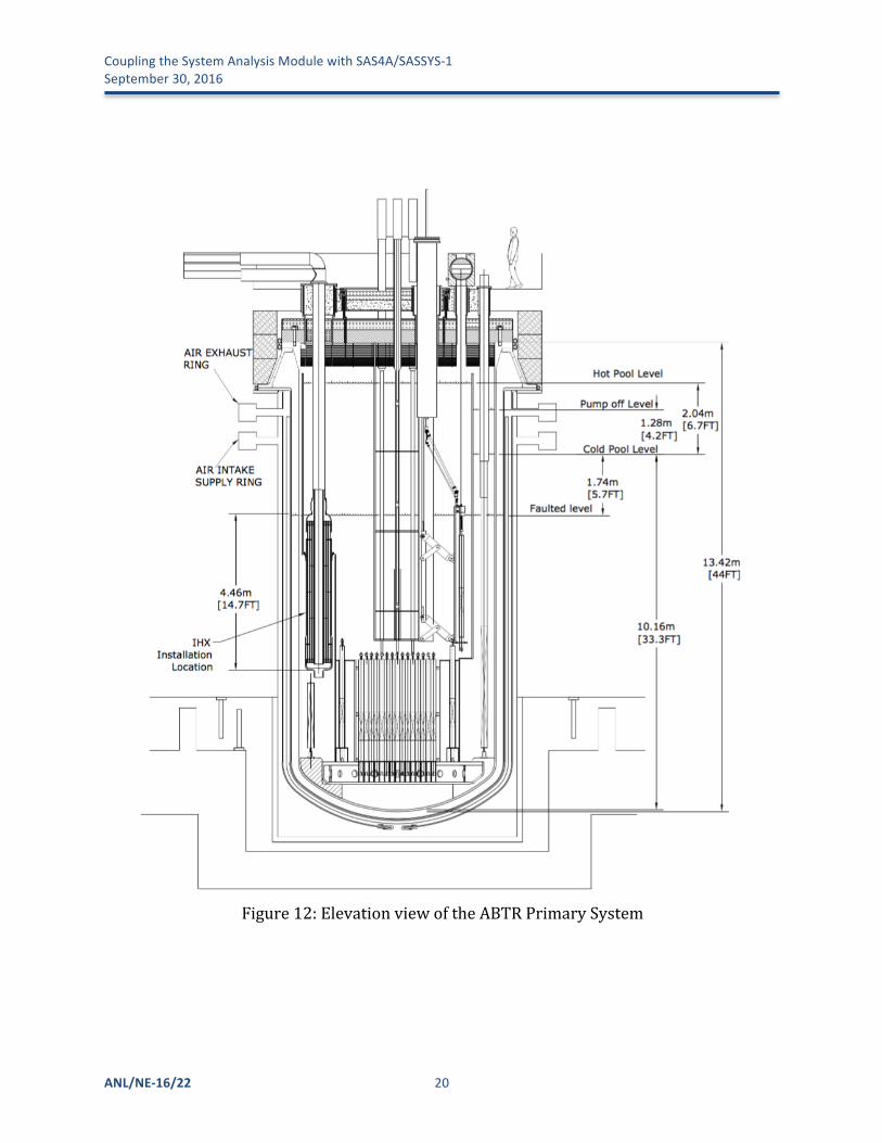
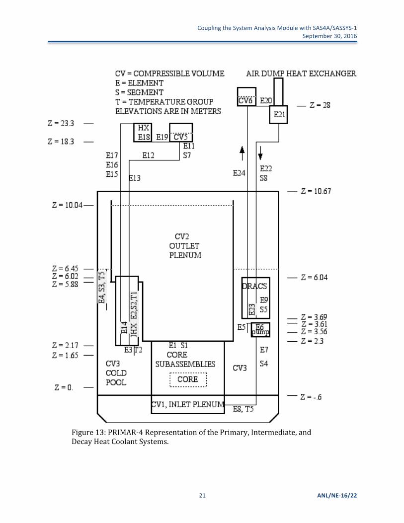
TheprimaryvesselconfigurationisshowninFigure12andthePRIMAR-4modelfortheprimary,intermediate,anddecayheatcoolantloopsisillustratedinFigure13.Largesodiumvolumesinthecoolantloopsaremodeledascompressiblevolumes(CVs)inPRIMAR-4.Forexample,CV1istheinletplenum,CV2istheoutletplenum(hotpool)andCV3isthecoldpool.Compressiblevolumesareconnectedbyliquidsegments.Inthismodel,segmentone(S1)isthesegmentrepresentingthecore,anditconnectstheinletplenumtotheoutletplenum.Segmentfour(S4)includestheprimarypumpandpipingthatconnectsthecoldpooltotheinletplenum.
Thecoresegment(S1)isuniquebecausePRIMAR-4usesthesurrogateparametersandEq.(1)toestimatecorechannelflowsduringtheprimarycoolantloopcalculations.Oncetheinletandoutletplenumconditionsareknown,theactualcorechannelflowsaredeterminedbythedetailedtransientcoreheattransferandpre-voidingandboilinghydraulicssolvers.
Figure11:ChannelAssignmentsfortheSAS4A/SASSYS-1CoreModel.
CouplingtheSystemAnalysisModulewithSAS4A/SASSYS-1September30,2016
ANL/NE-16/22 20
Figure12:ElevationviewoftheABTRPrimarySystem
CouplingtheSystemAnalysisModulewithSAS4A/SASSYS-1 September30,2016
21 ANL/NE-16/22
Figure13:PRIMAR-4RepresentationofthePrimary,Intermediate,andDecayHeatCoolantSystems.
CouplingtheSystemAnalysisModulewithSAS4A/SASSYS-1September30,2016
ANL/NE-16/22 22
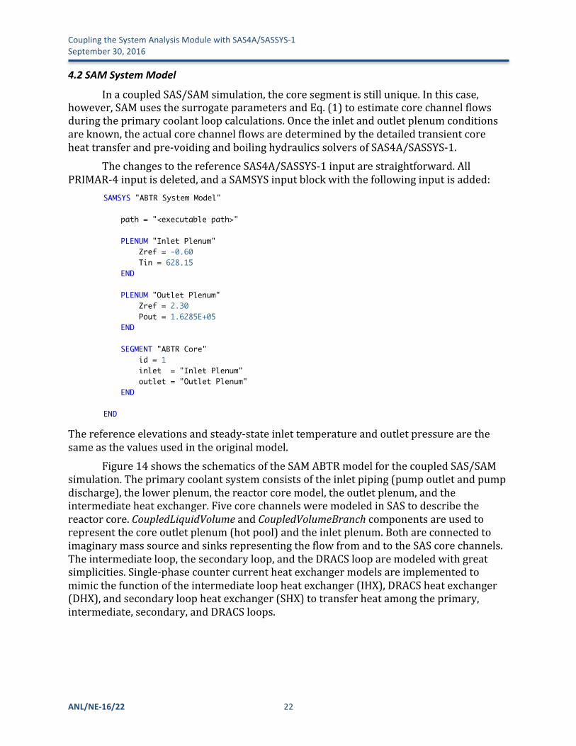
4.2 SAMSystemModel
InacoupledSAS/SAMsimulation,thecoresegmentisstillunique.Inthiscase,however,SAMusesthesurrogateparametersandEq.(1)toestimatecorechannelflowsduringtheprimarycoolantloopcalculations.Oncetheinletandoutletplenumconditionsareknown,theactualcorechannelflowsaredeterminedbythedetailedtransientcoreheattransferandpre-voidingandboilinghydraulicssolversofSAS4A/SASSYS-1.
ThechangestothereferenceSAS4A/SASSYS-1inputarestraightforward.AllPRIMAR-4inputisdeleted,andaSAMSYSinputblockwiththefollowinginputisadded:
Thereferenceelevationsandsteady-stateinlettemperatureandoutletpressurearethesameasthevaluesusedintheoriginalmodel.
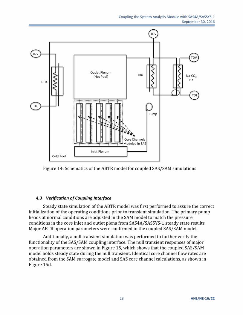
Figure14showstheschematicsoftheSAMABTRmodelforthecoupledSAS/SAMsimulation.Theprimarycoolantsystemconsistsoftheinletpiping(pumpoutletandpumpdischarge),thelowerplenum,thereactorcoremodel,theoutletplenum,andtheintermediateheatexchanger.FivecorechannelsweremodeledinSAStodescribethereactorcore.CoupledLiquidVolumeandCoupledVolumeBranchcomponentsareusedtorepresentthecoreoutletplenum(hotpool)andtheinletplenum.BothareconnectedtoimaginarymasssourceandsinksrepresentingtheflowfromandtotheSAScorechannels.Theintermediateloop,thesecondaryloop,andtheDRACSlooparemodeledwithgreatsimplicities.Single-phasecountercurrentheatexchangermodelsareimplementedtomimicthefunctionoftheintermediateloopheatexchanger(IHX),DRACSheatexchanger(DHX),andsecondaryloopheatexchanger(SHX)totransferheatamongtheprimary,intermediate,secondary,andDRACSloops.
Page 1/1untitled text
SAMSYS "ABTR System Model"1
2
path = "<executable path>"3
4
PLENUM "Inlet Plenum"5
Zref = -0.606
Tin = 628.157
END8
9
PLENUM "Outlet Plenum"10
Zref = 2.3011
Pout = 1.6285E+0512
END13
14
SEGMENT "ABTR Core"15
id = 116
inlet = "Inlet Plenum"17
outlet = "Outlet Plenum"18
END19
20
END21
22
23
24
CouplingtheSystemAnalysisModulewithSAS4A/SASSYS-1 September30,2016
23 ANL/NE-16/22
Figure14:SchematicsoftheABTRmodelforcoupledSAS/SAMsimulations
4.3 VerificationofCouplingInterface
SteadystatesimulationoftheABTRmodelwasfirstperformedtoassurethecorrectinitializationoftheoperatingconditionspriortotransientsimulation.TheprimarypumpheadsatnormalconditionsareadjustedintheSAMmodeltomatchthepressureconditionsinthecoreinletandoutletplenafromSAS4A/SASSYS-1steadystateresults.MajorABTRoperationparameterswereconfirmedinthecoupledSAS/SAMmodel.
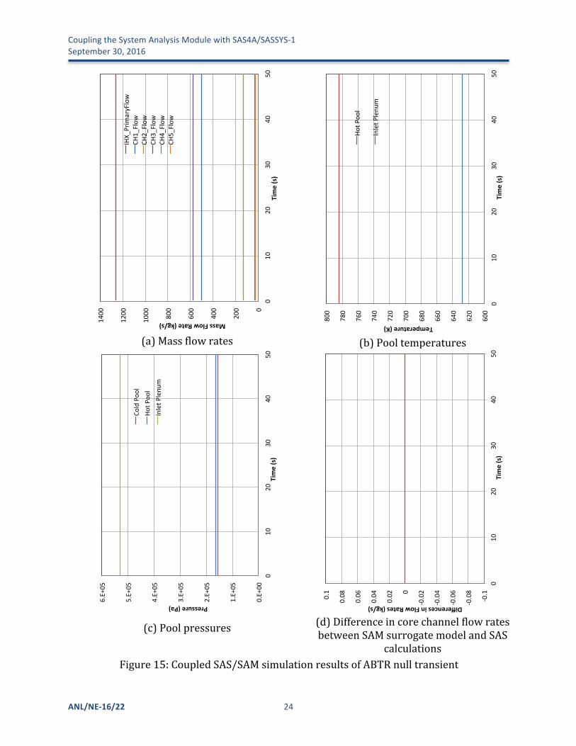
Additionally,anulltransientsimulationwasperformedtofurtherverifythefunctionalityoftheSAS/SAMcouplinginterface.ThenulltransientresponsesofmajoroperationparametersareshowninFigure15,whichshowsthatthecoupledSAS/SAMmodelholdssteadystateduringthenulltransient.IdenticalcorechannelflowratesareobtainedfromtheSAMsurrogatemodelandSAScorechannelcalculations,asshowninFigure15d.
TDV$
TDJ$
DHX$
Cold$Pool$Inlet$Plenum$
Outlet$Plenum$(Hot$Pool)$
TDV$
TDJ$
Pump$
IHX$ Na9CO2$HX$
Core$Channels$Modeled$in$SAS$
TDV$
CouplingtheSystemAnalysisModulewithSAS4A/SASSYS-1September30,2016
ANL/NE-16/22 24
(a)Massflowrates
(b)Pooltemperatures
(c)Poolpressures
(d)DifferenceincorechannelflowratesbetweenSAMsurrogatemodelandSAS
calculationsFigure15:CoupledSAS/SAMsimulationresultsofABTRnulltransient
0"
200"
400"
600"
800"
1000"
1200"
1400"
0"10"
20"
30"
40"
50"
Mass$Flow$Rate$(kg/s)$
Time$(s)$
IHX_
Prim
aryFlow"
CH1_Flow
"CH
2_Flow
"CH
3_Flow
"CH
4_Flow
"CH
5_Flow
"
600#
620#
640#
660#
680#
700#
720#
740#
760#
780#
800#
0#10#
20#
30#
40#
50#
Temperature)(K))
Time)(s))
Hot#P
ool#
Inlet#P
lenu
m#
0.E+00%
1.E+05%
2.E+05%
3.E+05%
4.E+05%
5.E+05%
6.E+05%
0%10%
20%
30%
40%
50%
Pressure&(Pa)&
Time&(s)&
Cold%Poo
l%Ho
t%Poo
l%Inlet%P
lenu
m%
!0.1%
!0.08%
!0.06%
!0.04%
!0.02%0%
0.02%
0.04%
0.06%
0.08%
0.1%
0%10%
20%
30%
40%
50%
Differences)in)Flow)Rates)(kg/s))
Time)(s))
CouplingtheSystemAnalysisModulewithSAS4A/SASSYS-1 September30,2016
25 ANL/NE-16/22
4.4 UnprotectedLossofFlowTransientSequence
Thebasicaccidentsequenceanalyzedisthelossofnormalpowertothereactorandintermediatecoolantpumpswithfailureoftheemergencypowersupplies.Theresultisalossofforcedflowintheprimaryandintermediatecoolantcircuits.Inaddition,itisassumedthattheflowrateinthepowercycleloopisreducetozeroimmediatelyfollowingtheaccidentsothattheonlyheatremovalpathisthroughtheemergencydirectreactorauxiliarycoolingsystem(DRACS).Itisalsoassumedthatthereactorsafetysystemisnotactivated,i.e.controlrodsarenotinsertedtoreducereactorpowerimmediately.Thissequenceisanunprotectedloss-of-flow(ULOF)accident.
ThenaturalcirculationDRACSismodeledasasimpleheatexchangerinthisdemonstrationproblem.Inletflowrate,inlettemperature,andoutletpressurearefixedonthesecondarysideasboundaryconditions.TheDRACSisdesignedtoremove0.5%offullpower(1250kW)atnormaloperatingtemperaturesassumingfailureofoneDRACSunit.Initialconditionsfortheaccidentsequencearenormaloperationsatfullpowerandflow.Withthelossofpumpingpower,flowintheprimarycircuitcoastsdownaccordingtothespinninginertiaofthepumpsandmotors.Followingflowcoastdown,naturalcirculationflowisestablished.Withthelossofpower,forcedflowintheintermediatecoolantsystemisalsolost,andcoastsdownaccordingtothecharacteristicsoftheintermediatepumps,whichisassumedtobesimilartotheprimarypumps.
IntheULOFsequence,thereactorsafetysystemfailstoscramthereactor,thusthereactorremainsatfullpowerinitially.Immediatelyfollowingtheaccident,reactortemperaturesincreaseasthecoolantflowratedecreases,andvariousreactivityfeedbackmechanismsreducethereactorpower.Ascoolantflowcontinuestodecrease,asecondtemperaturepeakoccursafterthefullstopofprimarypumpsandbeforefullnaturalcirculationisestablished.Oncenaturalcirculationisestablishedintheprimaryloop,thetemperaturescontinueincreasingslowlybecausetheDRACShasinsufficientheatremovalcapacitytoovercomeboththeearlydecayheatproductionandthestoredheatintheprimarycoolantsystem.Eventually,thedecayheatfallsbelowtheDRACScapacity,andthesystemtemperaturesdecline.
4.5 TransientSimulationResultsofUnprotectedLossofFlow
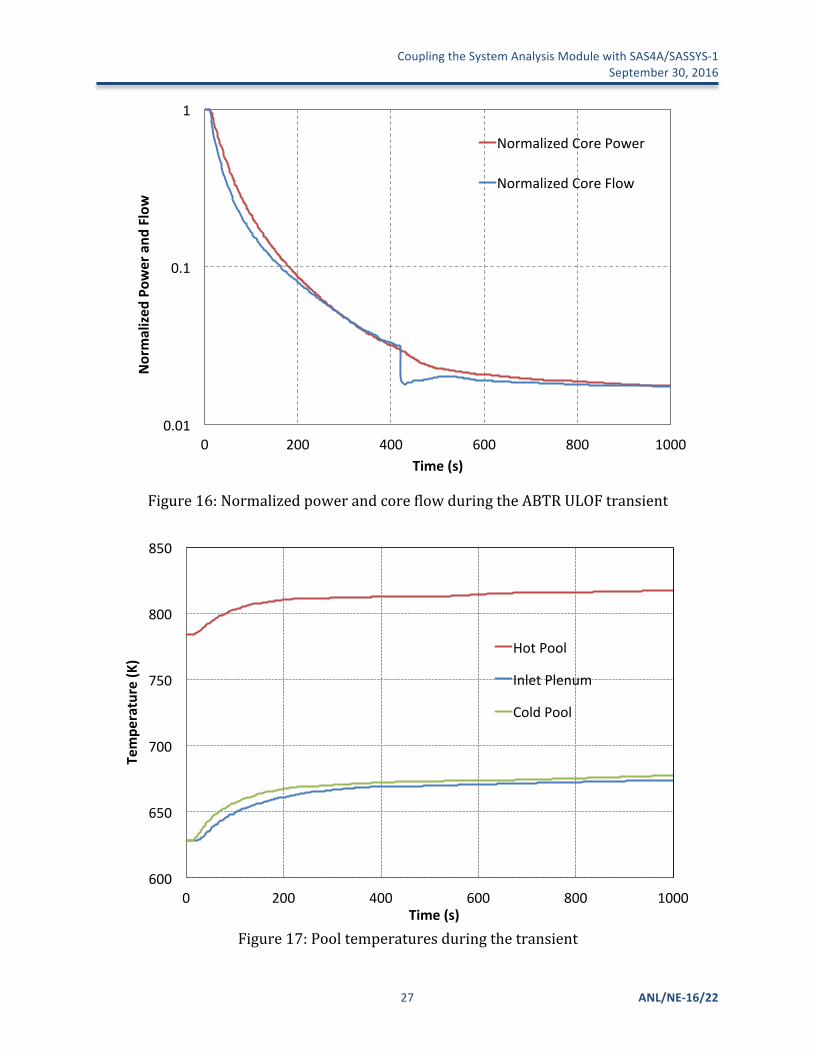
ResultsfromanalysisoftheearlypartoftheULOFtransient,duringthepumpcoastdownandtransitiontonaturalcirculation,areshowninFigure16–Figure21.ThenormalizedcorepowerandflowrateareshowninFigure16.Thistransientisinitiatedbyacompletelossofforcedcoolantflowintheprimaryandintermediateloops.Boththeprimaryandintermediatepumpsaredesignedwithsufficientflowinertiaanddonotceaseoperationuntilabout420secondsafterthestartofthetransient,followedbyatransitiontonaturalcirculation.Thepower-to-flowimbalanceresultsinsignificanttransientreactorheatingduringthefirst200seconds.
Thetemperaturesatthecoreinletplenum,outletplenum,andthecoldpoolareshowninFigure17.Shortlyafterthetransient,theonlyheatremovalisthroughtheDRACS.Therapidcoreflowreductionduetothepumptripleadstoarapidincreaseofthecoolantandfuelrodtemperaturesinthecoreandthentheoutletplenum.Thedropin
CouplingtheSystemAnalysisModulewithSAS4A/SASSYS-1September30,2016
ANL/NE-16/22 26
reactorpowerduetoinherentreactivityfeedbackstabilizesthehotpooltemperature.ColdpooltemperaturescontinuerisingduringthewholetransientbecausethehotcoolantcontinuesenteringthecoldpoolfromtheIHXoutlet.ThiswillcontinueuntiltheDRACSheatremovalcapabilitybecomesequaltothedecayheatproduction,whichwilloccuratabout5hours.Afterthat,thecoldpooltemperaturewilldecreaseasthewholesystemcools.Theinletplenumtemperatureresponsefollowsthesimilartrendofthecoldpooltemperatureresponse,butwithsomedelay.
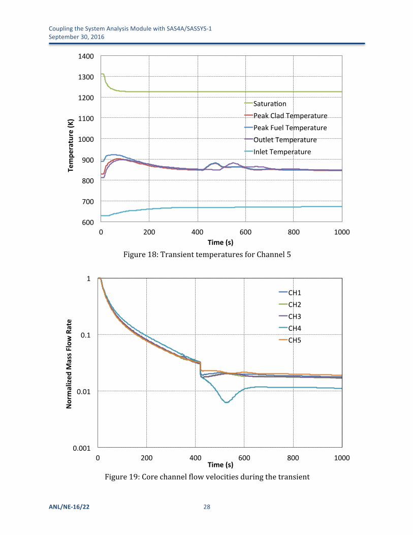
Peakfuel,peakclad,andcoolantoutlettemperaturesforchannel5(innercorepeakfuelassembly)areshowninFigure18.Thepeakfuel,cladding,andcoolanttemperaturesremainwellbelowthecoolantsaturation(boiling)temperature,withaminimummargintocoolantboilingofnearly300°C.Thissuggeststhatthecorewouldsurviveanunprotectedloss-of-flowaccidentwithoutpinfailuresorfueldamage.Figure19showsthemassflowrateinallcorechannelsduringthetransient.Similarbehaviorsarefound,andtheestablishmentsofthenaturalcirculationflowsoccuratthesametimeforallchannels.
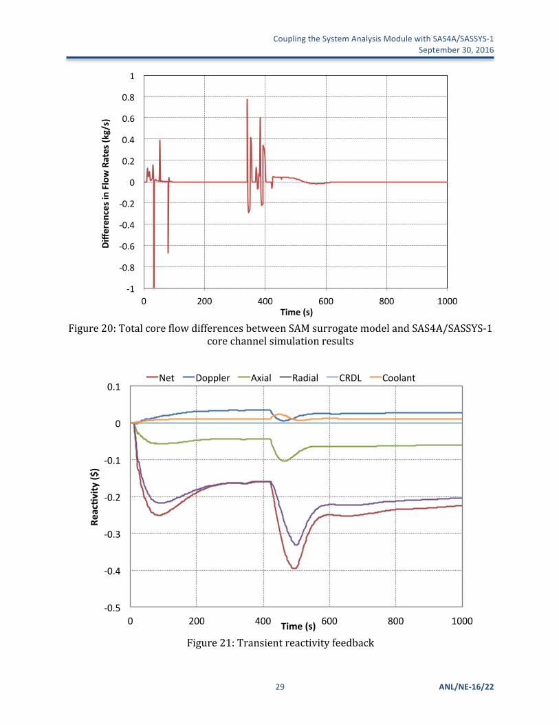
ThetotalcoreflowdifferencesbetweentheresultsfromtheSAMsurrogatemodelandSAS4A/SASSYS-1corechannelmodelareshowninFigure20.Differencesbetweenthetwomodelsareverysmallthroughoutthetransientandarelessthan0.1kg/smostofthetime.Thisdemonstratesthatthesurrogatemodelisabletoaccuratelyestimatethecorechannelflowrate,whichiscrucialfortheconvergencespeedandtheconsistencyinthecoupledSAS/SAMsimulationusingasequentialtwo-waycouplingscheme(asdiscussedinSection2).
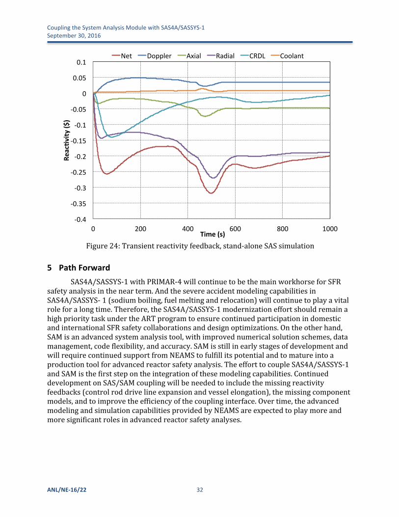
ThereactivityfeedbacksduringthetransientareshowninFigure21.AxialandRadialexpansionarethemaincontributorstotheinitialnegativereactivityfeedback,whichcausespowerandfueltemperaturestodecline.ReducedfueltemperaturesprovideapositiveDopplerfeedback,althoughthemagnitudeismodestduetothehighthermalconductivityandrelativelylowoperatingtemperaturesofmetallicfuel.Notethatthereactivityfeedbackduetothecontrol-roddrivelineexpansionarealwayszerointhecoupledSAS/SAMsimulationasthecontrolroddrivelineexpansionisnotsupportedthecurrentcoupling.Negativereactivityduetocontrol-roddrivelineexpansionwouldbeexpectedasthecontrol-roddrivelinesareheatedbyhighertemperaturecoolantshortlyaftertheonsetofthetransient.
CouplingtheSystemAnalysisModulewithSAS4A/SASSYS-1 September30,2016
27 ANL/NE-16/22
Figure16:NormalizedpowerandcoreflowduringtheABTRULOFtransient
Figure17:Pooltemperaturesduringthetransient
0.01$
0.1$
1$
0$ 200$ 400$ 600$ 800$ 1000$
Normalized
+Pow
er+and
+Flow+
Time+(s)+
Normalized$Core$Power$
Normalized$Core$Flow$
600#
650#
700#
750#
800#
850#
0# 200# 400# 600# 800# 1000#
Tempe
rature)(K
))
Time)(s))
Hot#Pool#
Inlet#Plenum#
Cold#Pool#
CouplingtheSystemAnalysisModulewithSAS4A/SASSYS-1September30,2016
ANL/NE-16/22 28
Figure18:TransienttemperaturesforChannel5
Figure19:Corechannelflowvelocitiesduringthetransient
600#
700#
800#
900#
1000#
1100#
1200#
1300#
1400#
0# 200# 400# 600# 800# 1000#
Tempe
rature)(K
))
Time)(s))
Satura0on#Peak#Clad#Temperature#Peak#Fuel#Temperature#Outlet#Temperature#Inlet#Temperature#
0.001$
0.01$
0.1$
1$
0$ 200$ 400$ 600$ 800$ 1000$
Normalized
+Mass+F
low+Rate++
Time+(s)+
CH1$CH2$CH3$CH4$CH5$
CouplingtheSystemAnalysisModulewithSAS4A/SASSYS-1 September30,2016
29 ANL/NE-16/22
Figure20:TotalcoreflowdifferencesbetweenSAMsurrogatemodelandSAS4A/SASSYS-1
corechannelsimulationresults
Figure21:Transientreactivityfeedback
!1#
!0.8#
!0.6#
!0.4#
!0.2#
0#
0.2#
0.4#
0.6#
0.8#
1#
0# 200# 400# 600# 800# 1000#
Diffe
rences)in)Flow)Rates)(k
g/s))
Time)(s))
!0.5%
!0.4%
!0.3%
!0.2%
!0.1%
0%
0.1%
0% 200% 400% 600% 800% 1000%
Reac%v
ity*($
)*
Time*(s)*
Net% Doppler% Axial% Radial% CRDL% Coolant%
CouplingtheSystemAnalysisModulewithSAS4A/SASSYS-1September30,2016
ANL/NE-16/22 30
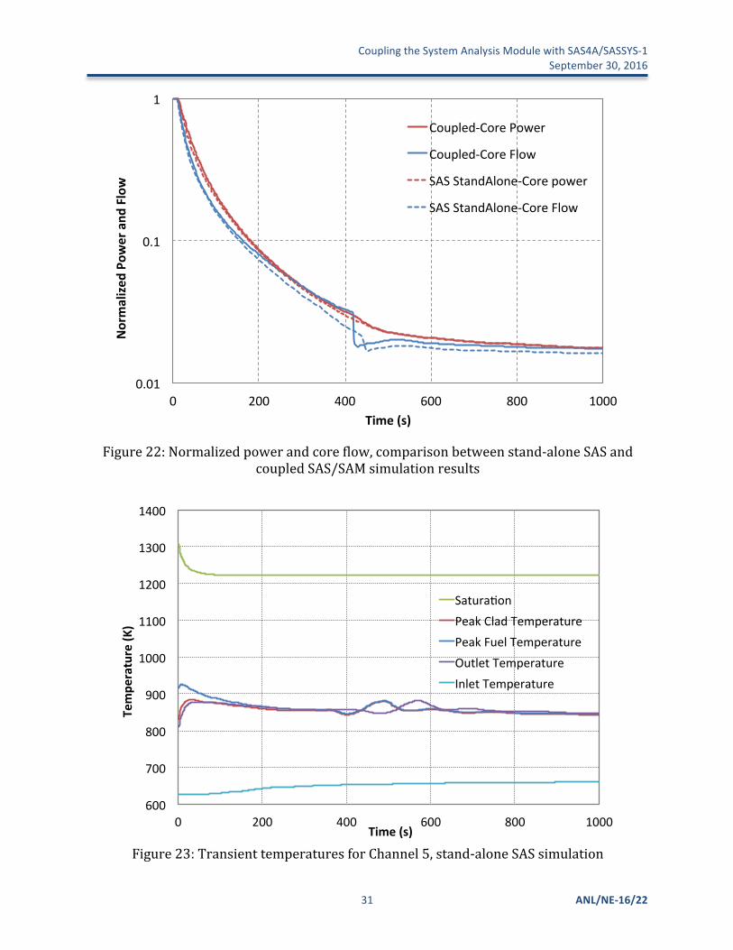
Thestand-aloneSAS4A/SASSYS-1simulationresultsoftheABTRULOFtransientarealsocomparedwiththecoupledSAS/SAMresults.ForconsistencywiththeSAMprimaryloopmodeling,theperfectmixingpoolmodelsareusedinthestand-aloneSAS4A/SASSYS-1simulation.
NormalizedcorepowerandflowratearecomparedinFigure22.Verysimilarcorepowersandflowrateswerepredictedthroughoutthetransientinthetwosimulations.Verysmalldifferencesinreactorpowerwerefoundintheinitial50sduetodifferencesinreactivityfeedbackduetocontrol-roddrivelineexpansion,andbetween390and410softhetransientduetodifferencesincoreflowratesandtemperatures.Thecoreflowrateswerealmostidenticalforthefirst150seconds,butdeviateslightlyfromeachotherlaterduetothedifferencesinpumpandloopfrictionmodeling.Thelargerdifferencesinflowratesbetween390and410sareattributedtodifferencesinmodelingthepumpresistanceafterthefullstopofthepumpimpeller.
Peakfuel,peakclad,andcoolantoutlettemperaturesforchannel5inthestand-aloneSAS4A/SASSYS-1simulationareshowninFigure23,andthereactivityfeedbacksareshowninFigure24.Notethatthereactivityfeedbacksduetocontrol-roddrivelineexpansionwereincludedinthestand-aloneSASsimulation.ComparingtheseresultstothecoupledSAS/SAMsimulation(Figure18andFigure21),thetransientresponse(bothtrendsandmagnitudes)areverysimilarbetweenthetwosimulations.
ThisdemonstrationsimulationfocusesontheearlystageoftheULOFtransient.ItshowsthatmajorphysicsphenomenaintheprimarycoolantloopcanbecapturedbythecoupledSAS4A/SASSYS-1andSAMsimulations.SomedifferenceswerefoundinthecoupledSAS/SAMsimulationresults.Thesecanbereducedbyaddressingtheknownmodelingdifferencesbetweenthetwosimulations.
CouplingtheSystemAnalysisModulewithSAS4A/SASSYS-1 September30,2016
31 ANL/NE-16/22
Figure22:Normalizedpowerandcoreflow,comparisonbetweenstand-aloneSASand
coupledSAS/SAMsimulationresults
Figure23:TransienttemperaturesforChannel5,stand-aloneSASsimulation
0.01$
0.1$
1$
0$ 200$ 400$ 600$ 800$ 1000$
Normalized
+Pow
er+and
+Flow+
Time+(s)+
Coupled0Core$Power$
Coupled0Core$Flow$
SAS$StandAlone0Core$power$
SAS$StandAlone0Core$Flow$
600#
700#
800#
900#
1000#
1100#
1200#
1300#
1400#
0# 200# 400# 600# 800# 1000#
Tempe
rature)(K
))
Time)(s))
Satura0on##Peak#Clad#Temperature#Peak#Fuel#Temperature#Outlet#Temperature#Inlet#Temperature#
CouplingtheSystemAnalysisModulewithSAS4A/SASSYS-1September30,2016
ANL/NE-16/22 32
Figure24:Transientreactivityfeedback,stand-aloneSASsimulation
5 PathForwardSAS4A/SASSYS-1withPRIMAR-4willcontinuetobethemainworkhorseforSFR
safetyanalysisinthenearterm.AndthesevereaccidentmodelingcapabilitiesinSAS4A/SASSYS-1(sodiumboiling,fuelmeltingandrelocation)willcontinuetoplayavitalroleforalongtime.Therefore,theSAS4A/SASSYS-1modernizationeffortshouldremainahighprioritytaskundertheARTprogramtoensurecontinuedparticipationindomesticandinternationalSFRsafetycollaborationsanddesignoptimizations.Ontheotherhand,SAMisanadvancedsystemanalysistool,withimprovednumericalsolutionschemes,datamanagement,codeflexibility,andaccuracy.SAMisstillinearlystagesofdevelopmentandwillrequirecontinuedsupportfromNEAMStofulfillitspotentialandtomatureintoaproductiontoolforadvancedreactorsafetyanalysis.TheefforttocoupleSAS4A/SASSYS-1andSAMisthefirststepontheintegrationofthesemodelingcapabilities.ContinueddevelopmentonSAS/SAMcouplingwillbeneededtoincludethemissingreactivityfeedbacks(controlroddrivelineexpansionandvesselelongation),themissingcomponentmodels,andtoimprovetheefficiencyofthecouplinginterface.Overtime,theadvancedmodelingandsimulationcapabilitiesprovidedbyNEAMSareexpectedtoplaymoreandmoresignificantrolesinadvancedreactorsafetyanalyses.
!0.4%
!0.35%
!0.3%
!0.25%
!0.2%
!0.15%
!0.1%
!0.05%
0%
0.05%
0.1%
0% 200% 400% 600% 800% 1000%
Reac%v
ity*($
)*
Time*(s)*
Net% Doppler% Axial% Radial% CRDL% Coolant%
CouplingtheSystemAnalysisModulewithSAS4A/SASSYS-1 September30,2016
33 ANL/NE-16/22
6 References1. T.H.Fanning,ed.,TheSAS4A/SASSYS-1SafetyAnalysisCodeSystem,ANL/NE-12/4,
NuclearEngineeringDivision,ArgonneNationalLaboratory,January31,2012.2. R.Hu,T.H.Fanning,T.Sumner,Y.Yu,“StatusReportonNEAMSSystemAnalysisModule
Development,”ANL/NE-15/41,ArgonneNationalLaboratory,December2015.
3. Y.Chang,P.Finck,andC.Grandy,“AdvancedBurnerTestReactorPreconceptualDesignReport,”ANL-ABR-1,ArgonneNationalLaboratory,Sept.5,2006.
Argonne National Laboratory is a U.S. Department of Energy laboratory managed by UChicago Argonne, LLC
Nuclear Engineering Division Argonne National Laboratory 9700 South Cass Avenue, Bldg. 208 Argonne, IL 60439-4842 www.anl.gov