course books - koyapete - petrolem...
TRANSCRIPT

Kurdistan Region - IRAQ Ministry of Higher Education & Scientific Research Koya University – Faculty of Engineering Petroleum Engineering Department
1
COURSE BOOKS
Electrical Engineering Technology
Second Stage
Academic Year: 2013-2014
Assistant Teacher: Caroline Daniel
E-mail: [email protected]
Kurdistan Region - IRAQ Ministry of Higher Education & Scientific Research Koya University – Faculty of Engineering Petroleum Engineering Department
2
Course Name Electrical Engineering Technology
Code PETE 208
Academic Year 2013-2014
Teacher in Charge Assistant Lecturer, Caroline Y. Daniel
Faculty / School /
Department Faculty of Engineering / petroleum Dept.
Contact details
Email: [email protected]
Class website:
https://sites.google.com/a/koyauniversity.org
Coordinator Name Dr.Nawzat Rashed Ismaeel
Coordinator Contact
Details [email protected]
Time Table
Grading
The students are required to do two closed book exams two times during
the academic year
besides the laboratory assignment;
1st Mid-term Exam: 30%
2nd
Mid-term Exam: 30%
Final Exam: 40%
Course Overview
Classes Wednesday : 01:30 – 3:30 PM ( Practical)
Monday: 08:30 – 10:30 PM ( Theory)
Electrical Engineering is introduced to understand the fundamentals of
electrical engineering. The aim of subject is to make familiar the
students with the basic terms, laws and theorems related to electrical
engineering. The subject also gives the little idea about electrical power
system, circuit theory and instrumentation. The subject also deals with
the electrical machines like transformer, motor and generator.

Kurdistan Region - IRAQ Ministry of Higher Education & Scientific Research Koya University – Faculty of Engineering Petroleum Engineering Department
3
Course Reading List:
1. Electricity, Priciples and Applications, Fowler, 6th Edition, copy
right 2003.
2. Principles of Electric Circuits, Floyd, 8th
Edition, copy right 2003.
3. Electrical Engineering, U. A. Bakshi and V. U. Bakshi, copy right
2008.
4. Basic Electrical Engineering, Pankaj Swarnkar, copy right 2009.
Weekly Course Outlines (3 hrs weekly)
Lecture Topic
1 Introduction, basic electrical quantities, elements and definitions.
2 Electrical Engineering Materials (conductors, semiconductors and insulators).
3 Resistors (resistance and resistivity), types of resistors, Ohm’s law, Temp effects.
4 DC power electrical cells and batteries (types and construction).
5 Electrical Energy, Power, and Efficiency.
6 Series circuits and KVL. Parallel circuits and KCL.
7 Star-Delta conversion, Electrical networks simplification.
8 Electrical networks simplification (cont.).
9 Network theorems (Mesh analysis, Nodal analysis).
10 Network theorems (Superposition theorem).
11 Network theorems (Thevenin’s theorem, Norton’s theorem).
12 Network theorems (Maximum power transfer theorem).
13 Capacitors and capacitance, Capacitors in series and in parallel.
14 Inductors and inductance, Inductors in series and in parallel.
15 AC fundamentals, Resistor, Capacitor and inductor in AC circuits.
16 Series AC circuits, Parallel AC circuits.
17 DC machines principles, construction and applications (DC generators).
18 DC machines principles, construction and applications (DC motors).
19 AC machines principles, construction and applications (AC generators).
20 AC machines principles, construction and applications (AC motors).
21 AC machines principles, construction and applications (transformers).
22 3-Phase principles.
23 3-Phase machines. (Introduction). 24 Electrical power transmission and distribution, Average power, Power Factor.
25 Electrical Cables and wires (types and sizes), Circuit breakers and Relays.
26 Industrial applications of electric machines in petroleum engineering
27 Industrial applications of electric machines in petroleum engineering (cont.)
28 Introduction of Renewable energy.
Kurdistan Region - IRAQ Ministry of Higher Education & Scientific Research Koya University – Faculty of Engineering Petroleum Engineering Department
4
1.Basic Definition:
Goal of lecture: Through this subject the student recognize the meaning
of the electrical engineering elements and theirs symbols.
Energy: is the capacity of doing any work, the unit of Energy is Joule (J).
Current: Electric current is defined as the time rate of net motion of
electric charge in any conductor and its unit is Ampere (A).
Potential: the work done to transfer unit positive charge from infinity to
any point in electric field and its unit is Volt (v).
Power: is defined as the time rate of change of energy.
Resistance: is the circuit constant which was introduced in 1826 by Ohm.
According to Ohms Law, the voltage across any branch is directly
proportional to the current passing through it and its unit is Ohm (Ω).
2. Ohms law of linear electrical resistors:
Ohms Law: this is the most fundamental law which was given by
ohm in 1825. According to this law, voltage in directly proportional
to current across any element when the physical conditions remain
constant. So the potential difference across any resistance is
Kurdistan Region - IRAQ Ministry of Higher Education & Scientific Research Koya University – Faculty of Engineering Petroleum Engineering Department
5
directly proportional to the current passing in it on condition
that the temperature is kept constant.
vαI
v=RI
Current Divider:
Voltage Divider:
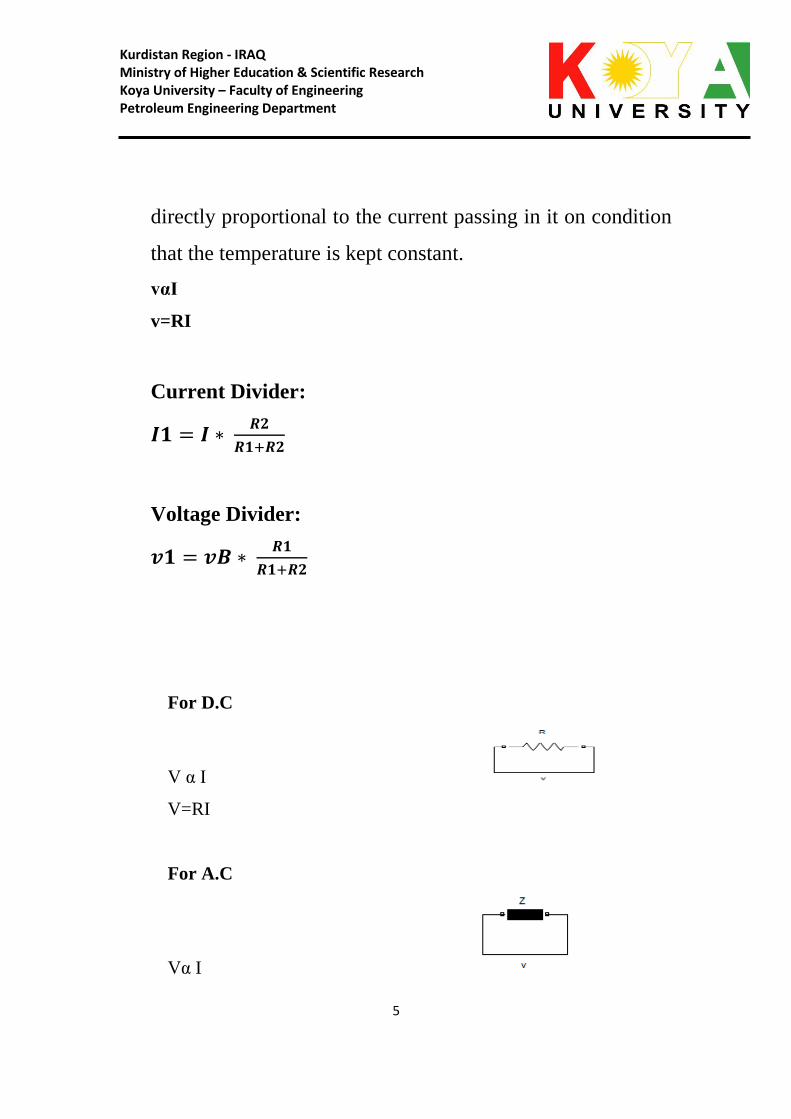
For D.C
V α I
V=RI
For A.C
Vα I
Kurdistan Region - IRAQ Ministry of Higher Education & Scientific Research Koya University – Faculty of Engineering Petroleum Engineering Department
6
V=Zi
Z=R+jX
3. Resistors Connections:
1.series connection:
Req=R1+R2
2. parallel connection:
Req=
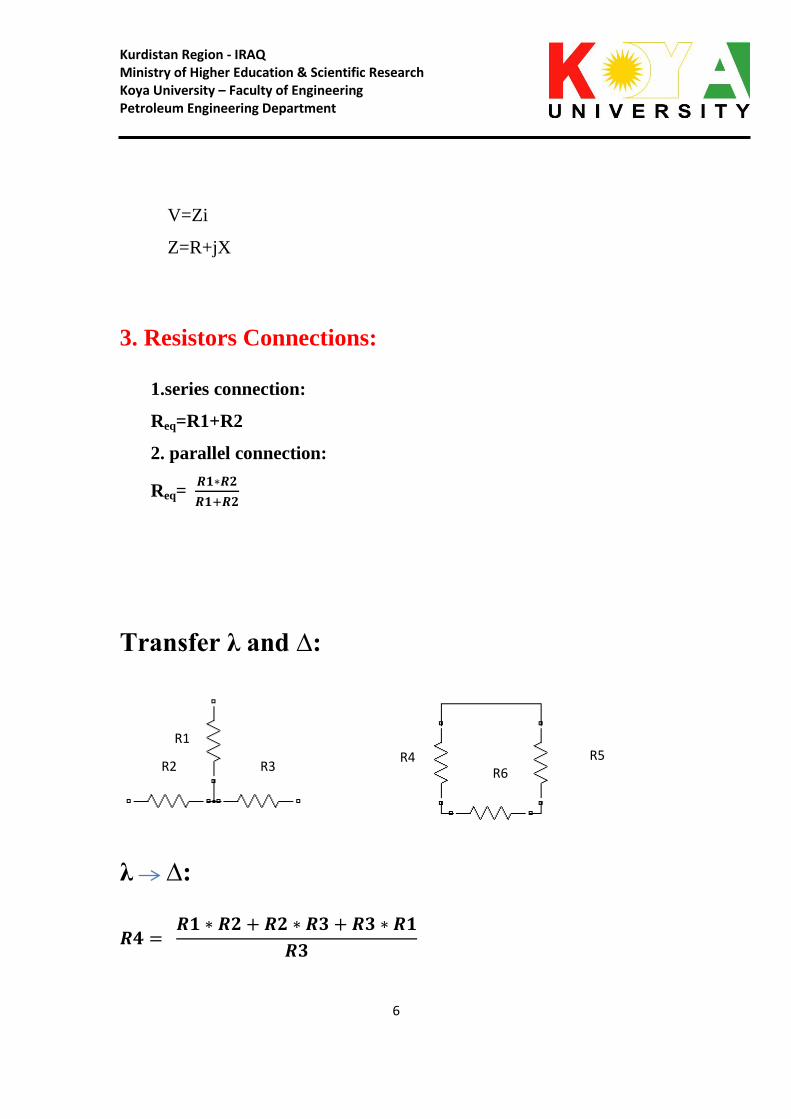
Transfer λ and ∆:
λ ∆:
R1
R2 R3 R4 R5
R6

Kurdistan Region - IRAQ Ministry of Higher Education & Scientific Research Koya University – Faculty of Engineering Petroleum Engineering Department
7
∆ λ :
4. Electrical networks theorems: 4.1 Kirchhoffs Law:
Kurdistan Region - IRAQ Ministry of Higher Education & Scientific Research Koya University – Faculty of Engineering Petroleum Engineering Department
8
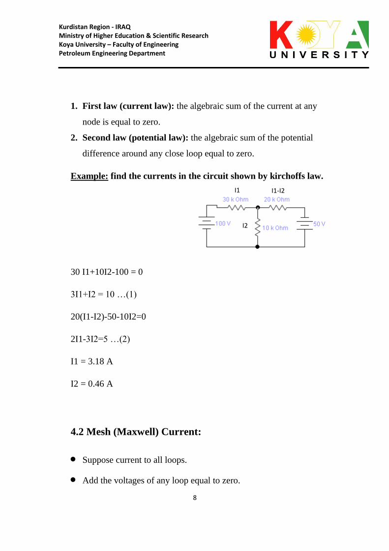
1. First law (current law): the algebraic sum of the current at any
node is equal to zero.
2. Second law (potential law): the algebraic sum of the potential
difference around any close loop equal to zero.
Example: find the currents in the circuit shown by kirchoffs law.
30 I1+10I2-100 = 0
3I1+I2 = 10 …(1)
20(I1-I2)-50-10I2=0
2I1-3I2=5 …(2)
I1 = 3.18 A
I2 = 0.46 A
4.2 Mesh (Maxwell) Current:
Suppose current to all loops.
Add the voltages of any loop equal to zero.
I1 I1-I2
I2

Kurdistan Region - IRAQ Ministry of Higher Education & Scientific Research Koya University – Faculty of Engineering Petroleum Engineering Department
9
Example. Find the current in each resistor using mesh method.
10 I1+20(I1 – I2) – 40 = 0
3I1 – 2I2 = 10 …(1)
30I2+70+40+20 (I2 – I1) = 0
5I2 – 2I1 = -11 …(2)
4.3 Nodal Analysis: in this method we select nodes and one
reference (ground) node. Since voltage is not the absolute quantity and
is always defined with respect to some reference or ground so we have
to choose one node as the reference whose voltage is zero.
Example. Find the current in each resistor using nodal analysis.
I1 I2
V1

Kurdistan Region - IRAQ Ministry of Higher Education & Scientific Research Koya University – Faculty of Engineering Petroleum Engineering Department
11
V1=42.85 volt
4.4 Super position Theorem: super position theorem states that in
any linear, active, bilateral network, having more than one source
response across any element is the sum of response obtained by each
source considered separately and all other sources are replaced by their
internal resistances.
Kurdistan Region - IRAQ Ministry of Higher Education & Scientific Research Koya University – Faculty of Engineering Petroleum Engineering Department
11
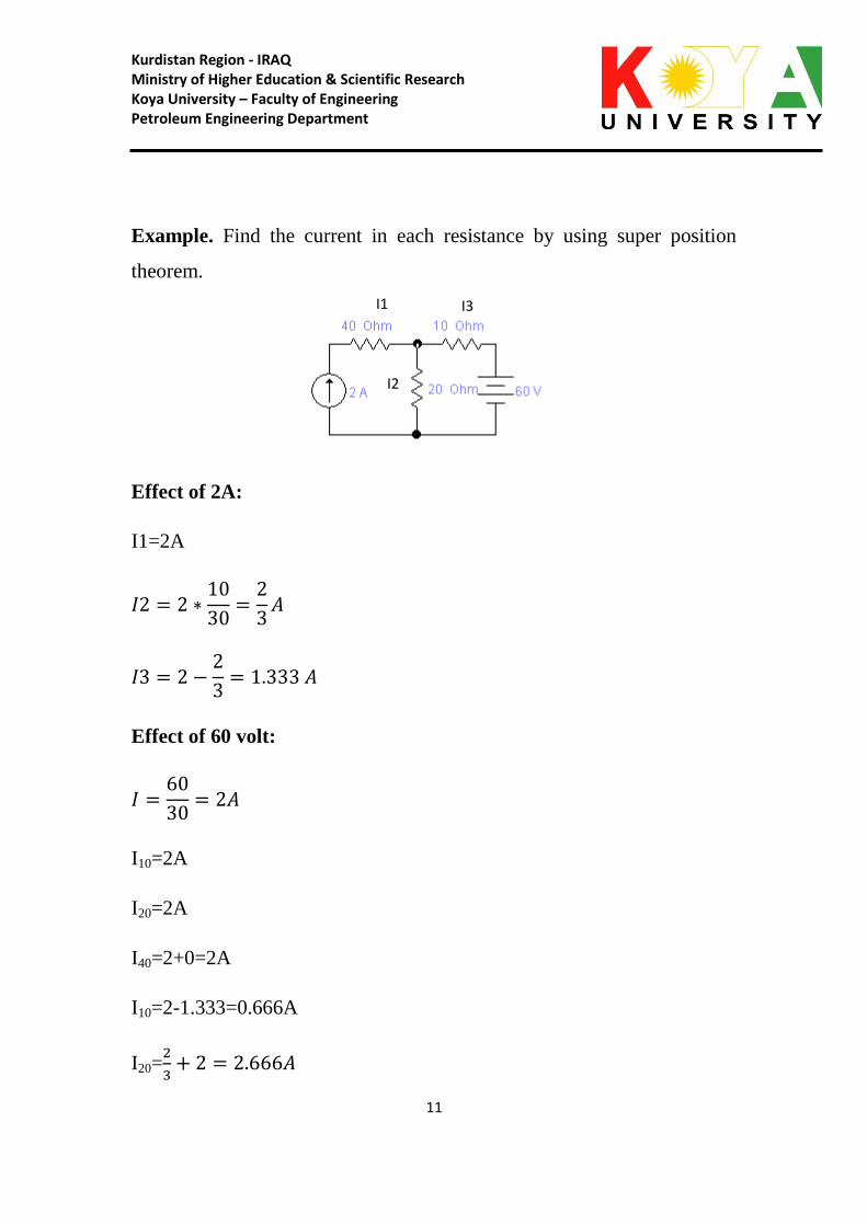
Example. Find the current in each resistance by using super position
theorem.
Effect of 2A:
I1=2A
Effect of 60 volt:
I10=2A
I20=2A
I40=2+0=2A
I10=2-1.333=0.666A
I20=
I1 I3
I2

Kurdistan Region - IRAQ Ministry of Higher Education & Scientific Research Koya University – Faculty of Engineering Petroleum Engineering Department
12
4.5 Thevenin Theorem: this theorem was proposed to solve the
complicated networks in 1883 by the French telegraph engineer Leon
Thevenin.
Any linear, active, bilateral complicated network across its load terminals
can replaced by single voltage source and one series resistance.
Example. Find the current in 60 ohm by using thevenin.
Vth=40*4=160 volt
Rth=30+10 // 40 =38ohm
4.6 Norton Theorem: the dual of thevenin theorem was given by E.
L. Norton of the Bell Telephone Laboratories. According to Norton
theorem: “any linear, active, bilateral complicated network across its load
terminals can be replaced by single current source and one parallel
resistance.

Kurdistan Region - IRAQ Ministry of Higher Education & Scientific Research Koya University – Faculty of Engineering Petroleum Engineering Department
13
Example. Find the current in 5ohm using Norton method.
Effect of 100 volt:
Rth=(15 // 30) // 60=8.57 ohm
5.Capacitors and Inductance:
5.1 Capacitors: Example:
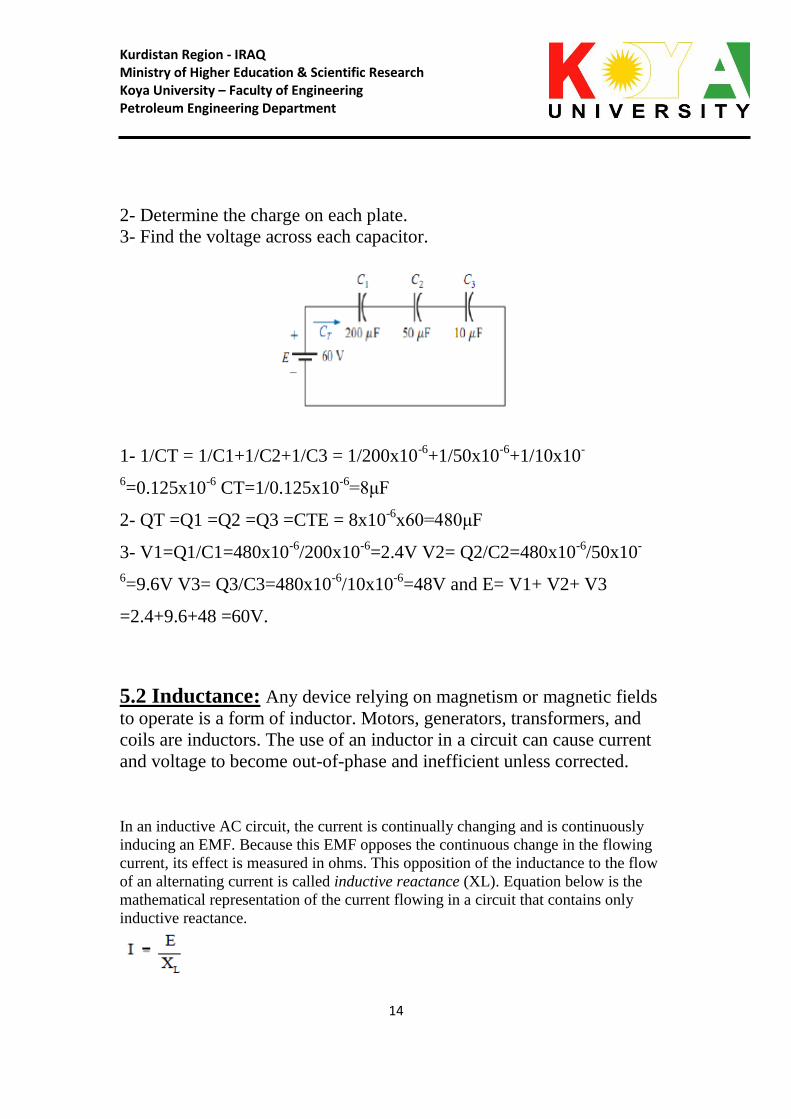
For the circuit in the figure:
1- Find the total capacitance.
Kurdistan Region - IRAQ Ministry of Higher Education & Scientific Research Koya University – Faculty of Engineering Petroleum Engineering Department
14
2- Determine the charge on each plate.
3- Find the voltage across each capacitor.
1- 1/CT = 1/C1+1/C2+1/C3 = 1/200x10-6
+1/50x10-6
+1/10x10-
6=0.125x10
-6 CT=1/0.125x10
-6=8μF
2- QT =Q1 =Q2 =Q3 =CTE = 8x10-6
x60=480μF
3- V1=Q1/C1=480x10-6
/200x10-6
=2.4V V2= Q2/C2=480x10-6
/50x10-
6=9.6V V3= Q3/C3=480x10
-6/10x10
-6=48V and E= V1+ V2+ V3
=2.4+9.6+48 =60V.
5.2 Inductance: Any device relying on magnetism or magnetic fields
to operate is a form of inductor. Motors, generators, transformers, and
coils are inductors. The use of an inductor in a circuit can cause current
and voltage to become out-of-phase and inefficient unless corrected.
In an inductive AC circuit, the current is continually changing and is continuously
inducing an EMF. Because this EMF opposes the continuous change in the flowing
current, its effect is measured in ohms. This opposition of the inductance to the flow
of an alternating current is called inductive reactance (XL). Equation below is the
mathematical representation of the current flowing in a circuit that contains only
inductive reactance.
Kurdistan Region - IRAQ Ministry of Higher Education & Scientific Research Koya University – Faculty of Engineering Petroleum Engineering Department
15
where
I = effective current (A)
XL = inductive reactance ()
E = effective voltage across the reactance (V)
The value of XL in any circuit is dependent on the inductance of the circuit and on the
rate at which the current is changing through the circuit. This rate of change depends
on the frequency of the applied voltage. Equation below is the mathematical
representation for XL.
= ~3.14
f = frequency (Hertz)
L = inductance (Henries)
6. AC fundamentals: No circuit is without some resistance, whether desired or not. Resistive
and reactive components in an AC circuit oppose current flow. The total
opposition to current flow in a circuit depends on its resistance, its
reactance, and the phase relationships between them. Impedance is
defined as the total opposition to current flow in a circuit. Equation below
is the mathematical representation for the magnitude of impedance in an
AC circuit.
where
Z = impedance ()
R = resistance ()
X = net reactance ()
Kurdistan Region - IRAQ Ministry of Higher Education & Scientific Research Koya University – Faculty of Engineering Petroleum Engineering Department
16
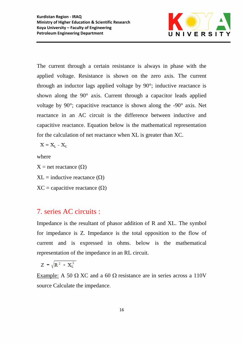
The current through a certain resistance is always in phase with the
applied voltage. Resistance is shown on the zero axis. The current
through an inductor lags applied voltage by 90°; inductive reactance is
shown along the 90° axis. Current through a capacitor leads applied
voltage by 90°; capacitive reactance is shown along the -90° axis. Net
reactance in an AC circuit is the difference between inductive and
capacitive reactance. Equation below is the mathematical representation
for the calculation of net reactance when XL is greater than XC.
where
X = net reactance ()
XL = inductive reactance ()
XC = capacitive reactance ()
7. series AC circuits :
Impedance is the resultant of phasor addition of R and XL. The symbol
for impedance is Z. Impedance is the total opposition to the flow of
current and is expressed in ohms. below is the mathematical
representation of the impedance in an RL circuit.
Example: A 50 XC and a 60 resistance are in series across a 110V
source Calculate the impedance.

Kurdistan Region - IRAQ Ministry of Higher Education & Scientific Research Koya University – Faculty of Engineering Petroleum Engineering Department
17
8. parallel AC circuits:
Total current in a parallel R-C-L circuit is equal to the square root of the
sum of the squares of the current flows through the resistance, inductive
reactance, and capacitive reactance branches of the circuit. Equations
below are the mathematical representations of total current in a parallel
R-C-L circuit. Because the difference between IL and IC is squared, the
order in which the quantities are subtracted does not affect the answer.
where
IT = total current (A)
IR = current through resistance leg of circuit (A)
IC = current through capacitive reactance leg of circuit (A)
IL = current through inductive reactance leg of circuit (A)
Example: A 200 resistor, a 100 XL, and an 80 XC are placed in
parallel across a

Kurdistan Region - IRAQ Ministry of Higher Education & Scientific Research Koya University – Faculty of Engineering Petroleum Engineering Department
18
120V AC source .Find: (1) the branch currents, (2) the total current,
and (3) the impedance.
Kurdistan Region - IRAQ Ministry of Higher Education & Scientific Research Koya University – Faculty of Engineering Petroleum Engineering Department
19
9. DC machines fundamentals:
9.1 DC Generator:
DC generators are widely used to produce a DC voltage. The amount of
voltage produced depends on a variety of factors.
There are three conditions necessary to induce a voltage into a conductor:
1. A magnetic field
2. A conductor
3. Relative motion between the two
A DC generator provides these three conditions to produce a DC voltage
output. A basic DC generator has four basic parts: (1) a magnetic field;
(2) a single conductor, or loop; -(3) a commutator; and (4) brushes
(Figure 7-1). The magnetic field may be supplied by either a permanent
magnet or an electromagnet. For now, we will use a permanent magnet to
describe a basic DC generator.
9.2 DC Motors:
DC motors are widely used to drive various equipment. The speed and
torque produced in a DC motor depends on a variety of factors. There are
two conditions which are necessary to produce a force on a conductor.
The conductor must be carrying current. The conductor must be within a

Kurdistan Region - IRAQ Ministry of Higher Education & Scientific Research Koya University – Faculty of Engineering Petroleum Engineering Department
21
magnetic field. When these two conditions exist, a force will be applied
to the conductor, which will attempt to move the conductor in a direction
perpendicular to the magnetic field. This is the basic theory by which all
DC motors operate.
10. AC machines fundamentals:
10.1AC Motors:
AC motors are widely used to drive machinery for a wide variety of
applications. To understand how these motors operate, a knowledge of
the basic theory of operation of AC motors is necessary.
The principle of operation for all AC motors relies on the interaction of a
revolving magnetic field created in the stator by AC current, with an
opposing magnetic field either induced on the rotor or provided by a
separate DC current source. The resulting interaction produces usable
torque, which can be coupled to desired loads throughout the facility in a
convenient manner. Prior to the discussion of specific types of AC
motors, some common terms and principles must be introduced.
10.2Induction Motors:
Various types of AC motors are used for specific applications. By
matching the type of motor to the appropriate application, increased
equipment performance can be obtained.
Kurdistan Region - IRAQ Ministry of Higher Education & Scientific Research Koya University – Faculty of Engineering Petroleum Engineering Department
21
Previous explanations of the operation of an AC motor dealt with
induction motors. The induction motor is the most commonly used AC
motor in industrial applications because of its simplicity, rugged
construction, and relatively low manufacturing costs. The reason that the
induction motor has these characteristics is because the rotor is a self-
contained unit, with no external connections. This type of motor derives
its name from the fact that AC currents are induced into the rotor by a
rotating magnetic field.
10.3Transformer:
Transformers are used extensively for AC power transmissions and for
various control and indication circuits. Knowledge of the basic theory of
how these components operate is necessary to understand the role
transformers play in today’s nuclear facilities.
11. 3Φ phase analysis:
A three- -phase
balanced
generator that produces three separate and equal voltages, each of which
is 120° out of phase with the other voltages.

Kurdistan Region - IRAQ Ministry of Higher Education & Scientific Research Koya University – Faculty of Engineering Petroleum Engineering Department
22
Three-phase equipment (motors, transformers, etc.) weighs less than
single-phase equipment of the same power rating. They have a wide
range of voltages and can be used for single-phase loads. Three-phase
equipment is smaller in size, weighs less, and is more efficient than
single-phase equipment.
Three-phase systems can be connected in two different ways. If the three
common ends of each phase are connected at a common point and the
other three ends are connected to a 3line, it is called a wye, or Y-. If the
three phases are connected in series to form a closed loop, it is called a
delta, or -, connection.
12. Instruments:
D’Arsonval - A DC moving coil movement where the moving coil is
suspended between the poles of a permanent magnet restrained by helical
springs, and the measured current flowing through the moving coil
produces a torque on the attached pointer proportional to the current.

Kurdistan Region - IRAQ Ministry of Higher Education & Scientific Research Koya University – Faculty of Engineering Petroleum Engineering Department
23
Electrodynamometer - The moving coil and attached pointer are
suspended between and connected in series with the two stationary field
coils so that the same current flows through each. A measured current
flowing through the three coils in either direction causes a magnetic
repulsion between the field coils and the moving coil. The magnetic
repulsion exerts a force against the spring and provides a measurement of
either DC or AC current.
Moving iron vane - The moving iron vane meter operates on the
principle of magnetic repulsion between like poles. The measured current
flows through a field coil which induces a like magnetic field into a fixed
and moving vane causing the moving vane to deflect a pointer in
proportion to the current or voltage applied to the coil.
Diodes:
• Diodes are essentially one-way current gates
• Symbolized by:
• Current vs. voltage graphs:
• Diodes are made of semiconductors (usually silicon)
• Essentially a stack of p-doped and n-doped silicon to form a p-n
junction
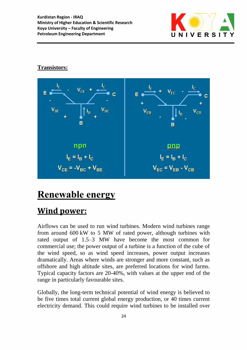
• Transistors are n-p-n or p-n-p arrangements of semiconductors
Kurdistan Region - IRAQ Ministry of Higher Education & Scientific Research Koya University – Faculty of Engineering Petroleum Engineering Department
24
Transistors:
Renewable energy
Wind power:
Airflows can be used to run wind turbines. Modern wind turbines range
from around 600 kW to 5 MW of rated power, although turbines with
rated output of 1.5–3 MW have become the most common for
commercial use; the power output of a turbine is a function of the cube of
the wind speed, so as wind speed increases, power output increases
dramatically. Areas where winds are stronger and more constant, such as
offshore and high altitude sites, are preferred locations for wind farms.
Typical capacity factors are 20-40%, with values at the upper end of the
range in particularly favourable sites.
Globally, the long-term technical potential of wind energy is believed to
be five times total current global energy production, or 40 times current
electricity demand. This could require wind turbines to be installed over
Kurdistan Region - IRAQ Ministry of Higher Education & Scientific Research Koya University – Faculty of Engineering Petroleum Engineering Department
25
large areas, particularly in areas of higher wind resources. Offshore
resources experience average wind speeds of ~90% greater than that of
land, so offshore resources could contribute substantially more energy.
Solar Energy:
Solar energy is the energy derived from the sun through the form of solar
radiation. Solar powered electrical generation relies on photovoltaics and
heat engines. A partial list of other solar applications includes space
heating and cooling through solar architecture, day lighting, solar hot
water, solar cooking, and high temperature process heat for industrial
purposes.
Solar technologies are broadly characterized as either passive solar or
active solar depending on the way they capture, convert and distribute
solar energy. Active solar techniques include the use of photovoltaic
panels and solar thermal collectors to harness the energy. Passive solar
techniques include orienting a building to the Sun, selecting materials
with favorable thermal mass or light dispersing properties, and designing
spaces that naturally circulate air.
Geothermal energy:
Geothermal energy is energy obtained by trapping the heat of the earth
itself, both from kilometers deep into the Earth's crust in volcanically
active locations of the globe or from shallow depths, as in geothermal
heat pumps in most locations of the planet. It is expensive to build a
power station but operating costs are low resulting in low energy costs for
suitable sites. Ultimately, this energy derives from heat in the Earth's
core.

Kurdistan Region - IRAQ Ministry of Higher Education & Scientific Research Koya University – Faculty of Engineering Petroleum Engineering Department
26
Kurdistan Region - IRAQ Ministry of Higher Education & Scientific Research Koya University – Faculty of Engineering Petroleum Engineering Department
27
Kurdistan Region - IRAQ Ministry of Higher Education & Scientific Research Koya University – Faculty of Engineering Petroleum Engineering Department
28

Kurdistan Region - IRAQ Ministry of Higher Education & Scientific Research Koya University – Faculty of Engineering Petroleum Engineering Department
29

Kurdistan Region - IRAQ Ministry of Higher Education & Scientific Research Koya University – Faculty of Engineering Petroleum Engineering Department
31
Kurdistan Region - IRAQ Ministry of Higher Education & Scientific Research Koya University – Faculty of Engineering Petroleum Engineering Department
31

Kurdistan Region - IRAQ Ministry of Higher Education & Scientific Research Koya University – Faculty of Engineering Petroleum Engineering Department
32