course introduction - renesas e-learning · course introduction ... magnitude comparators tgruu...
TRANSCRIPT

1© 2008, Renesas Technology America, Inc., All Rights Reserved
Course Introduction
� Purpose:
� This course provides an overview of the timer peripherals built into popular SH-2and SH-2A families of 32-bit RISC microcontrollers, which are members of theSuperH® series
� Objectives:
� Gain a basic knowledge of the capabilities, modes and applications of the multi-function timer pulse unit (MTU)
� Learn about the enhanced capabilities of the MTU2 and MTU2S peripherals innewer SH-2 and SH-2A devices
� Get details on the motor management timer, watchdog timer and compare-matchtimer
� Content:� 24 pages� 3 questions
� Learning Time:� 35 minutes

© 2008, Renesas Technology America, Inc., All Rights Reserved
SuperH Peripheral Functions
� Microcontrollers for embedded
system applications require
extensive on-chip peripherals to
� Minimize system chip count
� Reduce overall system cost
� Facilitate small system size, etc.
� Built-in peripheral functions must
� Provide required capabilities
� Deliver needed performance levels
� Offer design flexibility
� Maintain a basic commonality
within product family, if possible
� Offer an acceptable cost-benefit
compromise, etc.
SH-2 SuperH32-bit RISC CPU
MAC32/DSP Function
SH7047 SuperH Series Microcontroller
Multi-function TimerPulse Unit
Compare-MatchTimer
Watchdog Timer
Advanced User Debugger
Bus Interface
FLASH
Bus StateController
High-performanceUser Debug Interface
Clock PulseGenerator
RAM
Data TransferController
Interrupt Controller
User BreakController
I/O Ports
Motor Management Timer
Serial CommunicationInterface
Controller AreaNetwork Function
A/D Converter

© 2008, Renesas Technology America, Inc., All Rights Reserved
Multi-function Timer Pulse Unit
MTU:
� Provides multiple 16-bit timer channels
� Processes 16 pulse inputs/outputs
� Provides 8 clock inputs for each channel
� Offers standard and application-specific functions
(input capture, output compare sets/toggles output, counter clearing, etc.)
� Has 8 operating modes
� Provides 2-phase encoder up/down count
� Delivers 15mA output current
(can drive opto isolators directly)
� Is supported by a port-output-
enable function
� Has an A/D converter trigger
(with optional delay)
� Supports Module Stop mode
Vcc
MTUOutputPin
IOL=15mA
SH704x MCU
OptoIsolator
MTU Driving Opto Isolator

© 2008, Renesas Technology America, Inc., All Rights Reserved
MTU Operating Modes
� Ordinary Timer mode
� Each channel uses a counter and general register to create timing
events or measure timing signals
� Synchronized Timer mode
� Counters for multiple channels are synchronously preset
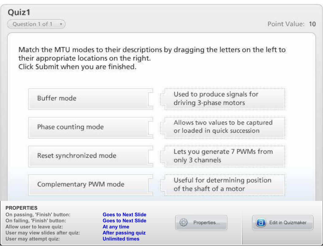
� Buffer mode
� For output-compare, next compare value is buffered
� For input-capture, previous capture value is buffered
� Two values can be captured or loaded in quick succession
� Cascade mode
� Channels 1 and 2 are combined in a cascade connection to form a
32-bit counter
- Overflow for channel 1 serves as the clock for channel 2

© 2008, Renesas Technology America, Inc., All Rights Reserved
MTU Operating Modes (cont’d)
� Phase Counting
� TCNT operates as up/down counter, depending on phase of
the external clock inputs for channels 1 and 2
� PWM (mode 1)
� Output of PWM signal can vary between 0% and
100% duty cycle
� Reset Synchronized PWM (mode 2)
� Outputs up to 8 PWM signals
� Waveforms share transition point on one side of signal repetition
� Complementary PWM
� Outputs three positive and three negative PWM waveforms
� Waveforms are centered and have no overlap
- Deadtime is inserted between signal switching operations

© 2008, Renesas Technology America, Inc., All Rights Reserved
MTU Block Diagram

© 2008, Renesas Technology America, Inc., All Rights Reserved
Buffer Mode
Output-compare operation
Input-capture operation
BufferRegister
TimerGeneral Register TCNT
Input-capturesignal
BufferRegister
TimerGeneralRegister
TCNT
Comparator generates signal when match occurs
Comparator

© 2008, Renesas Technology America, Inc., All Rights Reserved
Phase Counting Mode
Time
TCLKA (channel 1)
TCLKC (channel 2)
TCLKB (channel 1)
TCLKD (channel 2)
TCNT value
Increment Decrement
� Performs quadratureencoding
� Used to measure rotary displacement of motor armature, etc.
Phase Count Mode 1 — Up/Down Counting Conditions
TCLKA (channel 1) TCLKB (channel 1)
Operation TCLKC (channel 2) TCLKD (channel 2)
Increment 1 (high level) Rising edge
0 (low level) Falling edge
Rising edge 0 (low level)
Falling edge 1 (high level)
Decrement 1 (high level) Falling edge
0 (low level) Rising edge
Rising edge 1 (high level)
Falling edge 0 (low level)

© 2008, Renesas Technology America, Inc., All Rights Reserved
PWM Modes
Basic PWM (Mode 1)
� Each edge defined by a compare-match
� 1 output per pair of general registers
Reset synchronized (Mode 2)
� 1 output per general register
� 7 PWMs from only 3 channels!
� Channels 0, 1, 2: MTU2 only
MTU can generate up to
a 12-channel PWM
MTU can generate up to
a 12-channel PWM
TCNT Value
0xFFFF
TIOCA
Counter clear by TGRA compare match
Free-running Counter
TGRB
TGRA
0x0000
TCNT Value
0xFFFF
TGR1B
TGR1A
TGR0D
TGR0C
TGR0B
TGR0A
0x0000
TIOC0A
TIOC0B
TIOC0C
TIOC0D
TIOC1A
Counter clear by TGR1B compare match
Free-runningCounter

© 2008, Renesas Technology America, Inc., All Rights Reserved
Complementary PWM Mode
Output
0x0000
TGR3A
TCNT value
TCDR
TGR4A
TGR4C
TDDR
/Output
TCNT3
TCNT4
Deadtime Deadtime

© 2008, Renesas Technology America, Inc., All Rights Reserved
Data Updates
Data update timing: counter crest and trough
Countervalue
TGR3A
TGR4C
TGR4A
H’0000
BR
Temp_R
GR
data1
data1
data2
data2
data3
data3
data4
data4
data5
data5
data4
data6
data6
data6data1 data2 data3
Compare register
Buffer register
TCNTS
Transfers from temporary register to compare register
PROPERTIES
On passing, 'Finish' button: Goes to Next Slide
On failing, 'Finish' button: Goes to Next Slide
Allow user to leave quiz: At any time
User may view slides after quiz: After passing quiz
User may attempt quiz: Unlimited times

13© 2008, Renesas Technology America, Inc., All Rights Reserved
MTU2: 6-channel Timer
Extra timer (channel 5) supports:
� External pulse width measurement of 3 inputs
– Using input-capture capabilities, the actual delay between the complementary outputs can be measured in real time
� Deadtime compensation
– Channel 5 maintains safety margin by adding extra delay if normal deadtime won’t accommodate slow response of switching devices

14© 2008, Renesas Technology America, Inc., All Rights Reserved
The MTU2S Peripheral
Multi-function Timer pulse Unit 2S:
� Provides three 16-bit timers:
duplicates of MTU2 channels 3, 4
and 5
� Can operate at up to 100MHz
when generating complimentary
PWM waveforms, and at up to
33MHz when being used for other
functions
� Allows a microcontroller that
also has a MTU2 peripheral to
control two 3-phase motors
simultaneously
M2
M1
MTU2S
MTU2
SH7206

15© 2008, Renesas Technology America, Inc., All Rights Reserved
MTU Interrupts
� Interrupts can be generated at crests and troughs of the
triangular counting waveform
�MTU2 offers an interrupt skipping feature:
� Interrupts TGI3A (crest) and TCI4 (trough) in channels 3 and 4 can beskipped up to 7 times
� Transfers from a buffer register to a temporary register or compareregister can also be skipped
� A/D converter start requests can be skipped, as well

© 2008, Renesas Technology America, Inc., All Rights Reserved
Sources of MTU Interrupts
Channel 0
7 sources
• Compare match or
Input capture 0A
• Compare match or
Input capture 0B
• Compare match or
Input capture 0C
• Compare match or
Input capture 0D
• Compare match 0E
• Compare match 0F
• Overflow
Channel 1
4 sources
• Compare match or
Input capture 1A
• Compare match or
Input capture 1B
• Overflow
• Underflow
Channel 2
4 sources
• Compare match or
Input capture 2A
• Compare match or
Input capture 2B
• Overflow
• Underflow
Channel 3
5 sources
• Compare match or
Input capture 3A
• Compare match or
Input capture 3B
• Compare match or
Input capture 3C
• Compare match or
Input capture 3D
• Overflow
Channel 4
5 sources
• Compare match or
Input capture 4A
• Compare match or
Input capture 4B
• Compare match or
Input capture 4C
• Compare match or
Input capture 4D
• Overflow or
underflow
Channel 5*
3 sources
• Compare match
5U
• Compare match
5V
• Compare match
5W
* MTU2
Interrupt Sources

© 2008, Renesas Technology America, Inc., All Rights Reserved
Output Shutdown by POE2
Port Output Enable circuit (POE2):
� Provides a key safety feature, eliminates some external components
� Implements a protection circuit for inverters that shuts down
the power drive
� Is triggered by an external input signal (9 channels available)
� Accepts a falling-edge or low-level signal an an input
� Places the high-current pins in a high-impedance state (tri-state
condition) when their output levels are compared and a simultaneous low-
level output continues for one cycle or more
� Provides detection flags on each input pin
� Can request an interrupt to alert the application
� Operates independent of the main clock (works even when
clock fails)

© 2008, Renesas Technology America, Inc., All Rights Reserved
3-Phase AC Motor Control
SH-2 or SH-2A CPU
Ch 4
Ch 3
Ch 2
Ch 1
Ch 0
Watchdog Timer
10-bit A/D
SCI
I/O
ROM RAM
SCI
Amp
Current Detect (U and V phases)
Control Panel
EEPROM
QuadratureEncoder Inputs
3-Phase Output
15mA Sink Drive
MTU or MTU2
H Bridge
Typical Motor Drive Application
M

19© 2008, Renesas Technology America, Inc., All Rights Reserved
Motor Management Timer
MMT:
� Is a dedicated peripheral for driving motors included in some SH-2 series devices (SH7047, etc.)
� Outputs 6-phase PWM waveforms with non-overlap times
TBRU
Magnitude Comparators
TGRUU
TGRUU
TGRUU
TGRUU
TGRUU
TGRUU
TGRUU
TGRUU
TGRUU
TBRV TBRW MMT_TSR
TCNR
MMT_TMDR
Comparators
MMT_TCNT
Comparators
TPDR
TPBR MMT_TDDR
TDCNT0
PUOA
PUOB
PVOA
PVOB
PWOA
PWOB
PCIO
Clock
A/D startconversion
Control Circuit

PROPERTIES
On passing, 'Finish' button: Goes to Next Slide
On failing, 'Finish' button: Goes to Next Slide
Allow user to leave quiz: At any time
User may view slides after quiz: After passing quiz
User may attempt quiz: Unlimited times

21© 2008, Renesas Technology America, Inc., All Rights Reserved
Watchdog: Key Safety Feature
WDT:
� Can be used to detect/correct internal problems by restarting device
and applications if software runaways, etc., occur
� Must be periodically ‘tickled’ (set back to zero) to prevent an overflow that would generate an inadvertent reset signal
� Outputs a signal useful for resetting external devices
� Is driven by a choice of clocks
� Can also be used� as an interval timer to generate a periodic interrupt
� to ensure clock settling times are met when changing CPG frequency of SH-2A device in CPG and when leaving software standby mode
ResetControl
Internal Reset Signal
ITI (interruptrequest signal)
WDTOVFClock
Internal Clock Sources
WTCNTOverflow
Clock Select
WTSCR
BusI/F Module bus
Internal bus
InterruptControl
WRCSR

© 2008, Renesas Technology America, Inc., All Rights Reserved
Compare-Match Timer
CMT:
� Provides 2 channels of 16-bit compare-match timers and operates from 4 selectable internal clock sources
� Can generate interrupts at programmed intervals (software schedulers, etc.) and trigger DMAC
� Can be stopped when not needed to reduce power
Internal bus
Module bus
CMCSR_0
Comparator
Channel 0
CMCOR_0
CMCNT_0
CMI1
CMCSR_1
Comparator
CMCOR_1
CMCNT_1
Control Circuit
CMSTR
CMI0
Clock Selection Clock SelectionControl Circuit
BusI/F
Channel 1
Counter
Value
0x0000
Compareconstant register value
Counter cleared bycompare-match,status / interrupt set.

PROPERTIES
On passing, 'Finish' button: Goes to Next Slide
On failing, 'Finish' button: Goes to Next Slide
Allow user to leave quiz: At any time
User may view slides after quiz: After passing quiz
User may attempt quiz: Unlimited times

24© 2008, Renesas Technology America, Inc., All Rights Reserved
Course Summary
� MTU features and modes
� MTU2 and MTU2S
� Motor control application
� MMT
� WDT
� CMT