course no: m06-023 credit: 6 pdh of...this course is adapted from the u.s. department of health and...
TRANSCRIPT
Fundamentals of Fire Protection
Course No: M06-023 Credit: 6 PDH
Elie Tawil, P.E., LEED AP
Continuing Education and Development, Inc. 9 Greyridge Farm Court Stony Point, NY 10980
P: (877) 322-5800 F: (877) 322-4774

This course is adapted from the U.S. Department of Health and Human Services Public Health Service,
Centers for Disease Control and Prevention (CDC), National Institute for Occupational Safety and Health
(NIOSH) “Fire Protection” publication NIOSH Order No. 9637770 authored by James R. Mehaffey, PH.D.,
& Joel L. Bert PH.D.; which is in the public domain, is authorized for unlimited distribution and is not
copyrighted.

CONTENTS
UNIT I - BACKGROUND Purpose; Objectives; Special Terms ............................................ 1-1 FIRE LOSS STATISTICS .................................................. 1-2 REGULATORY FRAMEWORK .............................................. I-2
Building codes; Fire prevention codes . . . . . . . . . . . . . . . . . . . . . . . . . . . . . . . . . . . . . . I-2 National Fire Protection Association; Occupational Safety and Health Administration; Testing laboratories; Consumer protection; Insurance carriers . . . . . . . . . . . . . . . . . . . . . . . . I-3
FIRE PROTECTION ENGINEERING . . . . . . . . . . . . . . . . . . . . . . . . . . . . . . . . . . . . . . . . . . 1-3 ORGANIZATION OF MODULE ............................................. 1-4 REFERENCES . . . . . . . . . . . . . . . . . . . . . . . . . . . . . . . . . . . . . . . . . . . . . . . . . . . . . . . . 1-5
UNIT II - INTRODUCTION Purpose; Objectives; Special Terms ............................................ II-I FIRE SAFETY OBJECTIVES ............................................... 11-2 FIRE HAZARDS ....................................................... 11-2 FIRE PERFORMANCE OF MATERIALS ....................................... 11-3
UNIT III - FUNDAMENTALS OF FIRE SCIENCE Purpose; Objectives; Special Terms . . . . . . . . . . . . . . . . . . . . . . . . . . . . . . . . . . . . . . . . . . . 111-1 INTRODUCTION . . . . . . . . . . . . . . . . . . . . . . . . . . . . . . . . . . . . . . . . . . . . . . . . . . . . . . 111-2 FIRE TETRAHEDRON . . . . . . . . . . . . . . . . . . . . . . . . . . . . . . . . . . . . . . . . . . . . . . . . . . 111-2 FIRE AS A CHEMICAL REACTION . . . . . . . . . . . . . . . . . . . . . . . . . . . . . . . . . . . . . . . . . III-3 TYPE OF FUEL ...................................................... 111-4
Vapor ........................................................ 111-4 Liquid . . . . . . . . . . . . . . . . . . . . . . . . . . . . . . . . . . . . . . . . . . . . . . . . . . . . . . . . 111-5 Solid . . . . . . . . . . . . . . . . . . . . . . . . . . . . . . . . . . . . . . . . . . . . . . . . . . . . . . . . . 111-6
FLAMING COMBUSTION ................................................ III-7 Oxidant . . . . . . . . . . . . . . . . . . . . . . . . . . . . . . . . . . . . . . . . . . . . . . . . . . . . . . . III-9
IGNITION SOURCES . . . . . . . . . . . . . . . . . . . . . . . . . . . . . . . . . . . . . . . . . . . . . . . . . . . III-9 REFERENCES ..................................................... III-10 SAMPLE QUIZ QUESTIONS . . . . . . . . . . . . . . . . . . . . . . . . . . . . . . . . . . . . . . . . . . . . . III-11
UNIT IV - DYNAMICS OF FIRE Purpose; Objectives; Special Terms ........................................... IV-1 INTRODUCTION ...................................................... IV-2 HEAT TRANSFER IN FIRES .............................................. IV-2
Conductive heat transfer; Convective heat transfer .............................. IV-2 Radiative heat transfer . . . . . . . . . . . . . . . . . . . . . . . . . . . . . . . . . . . . . . . . . . . . . . . IV-3
ROOM FIRE DYNAMICS ................................................ IV-4 PREFLASHOVER FIRES ................................................. IV-5 POSTFLASHOVER FIRES ................................................ IV-6 SMOKE PRODUCTION .................................................. IV-7
Smoke toxicity; Toxic fire gases . . . . . . . . . . . . . . . . . . . . . . . . . . . . . . . . . . . . . . . . . IV-8 Toxic potency . . . . . . . . . . . . . . . . . . . . . . . . . . . . . . . . . . . . . . . . . . . . . . . . . . . . IV-9
REFERENCES ....................................................... IV-9 SAMPLE QUIZ QUESTIONS ............................................. IV-10
UNIT V - PRINCIPLES OF FIRE PROTECTION Purpose; Objectives; Special Tenns ............................................ V-1 INTRODUCTION ....................................................... V-2 FIRE SAFETY CONCEPTS TREE ............................................ V-2
Fire safety objectives ................................................. V-2 Prevent fire ignition . . . . . . . . . . . . . . . . . . . . . . . . . . . . . . . . . . . . . . . . . . . . . . . . . V -3 Manage fire impact . . . . . . . . . . . . . . . . . . . . . . . . . . . . . . . . . . . . . . . . . . . . . . . . . . V-4
THE PROVISION OF FIRE SAFETY .........................................• V-8 REFERENCES ........................................................ V-8 SAMPLE QUIZ QUESTIONS ...........................•.•.• , . , ............ V-9
UNIT VI - FIRE DETECTION Purpose; Objectives; Special Tenns ........................•...........•...... VI-1 INTRODUCTION ................................. , . . . • . . . . . . . . . . . . . . . . VI-2 FIRE ALARM SYSTEMS . . . . . . . . . . . . . . . . . . . . . . . . . . . . . . . . . . . . . . . . . . . . . . . . . VI-2 DETECTION DEVICES . . . . . . . . • . . . . . . . . . . . . . . . . . . . . . . . . . . . . . • . . . . . . . . . . . VI-2
Fire signature .•............... , . . . . . . . . . . . . . . . . . . • . . . • . . . . . . . . . . . VI-2 Aerosol detectors ......•........ , ................•.................. VI-3 Heat detectors . . . . . . . . . . . . . . • . . . . . . . . . . . . . . . . . . . . . . . . . . • , . . . . . . . . . VI-4 Infrared and ultraviolet flame detectors . . . . . . . . . . . . . . . . . . . . . . . . . . . . . . . . . . • . . VI-7 Gas sensing detectors . . . . . . . . . . . . . . . . . . . . . . . . . . . . . . . . • , . . . . . . • . . . . . . VI-8
FIRE DETECTION SYSTEM CONCERNS . . . . . . . . . . . . . . . . . . . . . . . . . . . . . . . . . . . . . . VI-9 Fire alarm system details . . . . . . . . . . . . . . . . . . . . . . . . . . . . . . . . . . . . . . . • . . . . . VI-9
REFERENCES ...................................... , ........•....... VI-9 SAMPLE QUIZ QUESTIONS ............................. , , . . . . • . . • . . . . . . . VI-9
UNIT VII - FIRE SUPRESSION Purpose; Objectives; Special Tenns . • . . . . . . . . . . . . . . . . . . . . . • . . . . , . • . . . . . . • . . . . . VII-1 INTRODUCTION................................... , .................. VII-2 THEORY OF SUPPRESSION .................•..........•.........•.•..... VII-2
Water • . . • . . . . . . . . • . . • . . . . . . . . . . . . . . . . . . • . . • . . . . . . . . . . . . • . . . . . VII-2 Foams; Carbon dioxide. • . . . . . . . . . . • . . . . . . . . . . . . . . . . . , • • . • . . . . . . • . . • . VII-3 Halon; Dry chemicals .•............................... · ......... , .... VII-4
AUTOMATIC SUPPRESSION SYSTEMS ................. , ............•.•.•... VII-4 Automatic water sprinkler systems . . . . . . . . . . . . . . . . . . . . , . . . • . . . . . . . . . . . . . . VII-4 Foam extinguishing systems ...............................•........... VII-5 Carbon dioxide systems; Halon extinguishing systems; Dry chemical systems ............. VII-6
SUPPRESSION BY THE FIRE SERVICES ...................................... VII-6 In-house fire brigades ..•............................•.•............. VII-6 Public fire departments ......................... , ............•....... VII-7
PORTABLE FIRE EXTINGUISHERS ......................................... VII-7 Water based extinguishers ............................................ VII-8 Foam extinguishers; Carbon dioxide extinguishers; Dry chemical extinguishers; Class D extinguishers .............................. VII-9
REFERENCES ............•... · ....................................... VII-10 SAMPLE QUIZ QUESTIONS ..............•.............................. VII-10
GLOSSARY. . . . • . . . . . . . . • . . . . . . .· . . . . . . . . . . . . , . . . . . . : .. . , . . . . . . . . . . • . VIII-1

Unit I
BACKGROUND
PURPOSE:
OBJECTIVES:
SPECIAL TERMS:
To provide an overview of the losses that result from fire and the regulations that are
adopted to prevent and abate this threat.
To provide an overview of:
1. Fire loss statistics related to injury and death
2. Fire loss statistics related to property damage and business interruption
3. The regulatory framework intended to ensure fire safety
4. The organization of this module
1. Fire loss statistics
2. National Fire Protection Association (NFPA)
3. Occupational Safety and Health Administration (OSHA)
4. Building codes
5. Fire prevention codes
6. Fire standards
7. Fire performance
8. Prescriptive codes
9. Performance-based codes
10. Fire protection engineering
I -1
FIRE LOSS
STATISTICS
REGULATORY
FRAMEWORK
Building codes
Fire prevention
codes
Fires extract a high toll in injuries and in loss of human life. In the United States,
occupational fatalities account for more than 3% of all deaths related to fires1• This
figure translates into about 40 deaths per year associated with industrial and
manufacturing fires in addition to the approximately 750 injuries from these fires2•
Statistics generated by the National Fire Protection Association show that during the
period 1988-1993 industrial and manufacturing fires accounted for annual property losses
of about $1.0 billion2• More recently, 1995 direct property losses due to all fires in the
United States have been estimated to be nearly $8 billion3. Although residential fires
accounted for approximately 60 % of these losses, industrial property damage was also
high and estimated to be $1.3 billion. This figure represents a significant increase from
the previous year. Losses associated with storage in structures also increased
dramatically in 1995 to more than $700 million.
Although the causes of industrial and manufacturing fires are often difficult to determine,
the major sources of ignition appear to be: manufacturing, electrical or heating
equipment; open flames; and incendiary sources. Because of the diverse nature of the
causes of industrial fires, protective measures must be carefully engineered for specific
industrial processes and their hazards.
Although these fire statistics are significant, they represent an improvement in fire safety
compared with past experience. Much of this improvement results from the regulatory
framework that has been established to ensure that fire safety objectives are met
throughout the United States. Although this regulatory framework is multi-layered and
complex, the simplified picture that follows shows how it is structured and how it works.
Three private organizations have developed and maintain three model building codes in
the United States: the International Conference of Building Officials (ICBO), the Southern
Building Code Congress International (SBCCI), and the Building Officials and Code
Administrators (BOCA). Among other functions, these codes provide a set of fire safety
provisions intended to ensure that an acceptable level of life safety is incorporated into
buildings at the time of their construction. The codes use fire safety standards developed
by the National Fire Protection Association (NFPA) and the American Society for Testing
and Materials (ASTM).
States and municipalities adopt one of these model codes to form the basis of local
building regulations. Enforcement of these regulations is the responsibility of local (and
sometimes State) building inspectors. As a consequence both the letter of the law and
its enforcement may vary somewhat from place to place.
The NFPA has developed and maintains NFPA 1, a model fire prevention code4
• The
code offers provisions intended to ensure that, following construction, buildings are
equipped, operated and maintained to provide an acceptable level of life safety and
property protection from potential hazards created by fires or explosions. NFPA 1 makes
reference to 97 other codes and standards developed by the NFPA to address various
specific fire safety concerns.
State and local jurisdictions have adopted NFPA 1 as the basis of their fire prevention
regulations. Again, enforcement of these regulations is the responsibility of local and
State officials including fire service personnel.
I-2
National Fire
Protection
Association
Occupational
Safety and Health
Administration
Testing
laboratories
Consumer
protection
Insurance carriers
FIRE
PROTECTION
ENGINEERING
The National Fire Protection Association (NFPA) is a nonprofit organization that
develops and publishes codes and standards intended to minimize the occurrence and
effects of fire in all aspects of contemporary activity. The more than 290 codes and
standards of the NFPA are developed by committees comprised of expert volunteers from
various backgrounds. Some of these codes and standards delineate standard practices for
designing facilities, installing equipment or undertaking inspections. Others describe
standardized methods for conducting fire tests on personal protective equipment, building
products and fire protection equipment. These codes and standards are widely used as
the basis of legislation and regulation at all levels of government, from local to Federal.
Many are referenced by agencies of the Federal government, such as the Occupational
Safety and Health Administration (OSHA). NFPA codes and standards are also used by
insurance authorities for risk evaluation and premium rating.
The provision of workplace safety is the purview of the Occupational Safety and Health
Administration (OSHA), an agency of the U.S. Department of Labor. OSHA has a
mandate to provide workplace fire protection and explosion prevention standards and
regulations to ensure safe working conditions. To achieve its mandate, OSHA generates
its own standards and also often adopts standards developed by the NFPA.
The provision of fire safety relies heavily on NFPA standard fire tests. Several
accredited testing laboratories are available to undertake such testing and, hence, to
document the fire performance of personal protective equipment, building products, and
fire protection equipment.
Consumer protection departments of Federal and State governments are concerned with
the fire performance of commercial products such as furnishings, which may not be
regulated by building codes or fire prevention codes. These departments have
implemented programs that limit the consumer's choice to products with acceptable fire
performance.
Although not strictly part of the regulatory framework, insurance carriers play an
important role in fire safety provision. Insurance carriers are concerned with the
potential for loss of life and property damage resulting from fires. Insurance companies
have developed methods for assessing the fire risk in a facility to levy appropriate
premiums. For large facilities, such as in industry, assessment methods can involve
advanced engineering analysis. The Factory Mutual System and Underwriters
Laboratories Inc. provide engineering services to support insurance carriers. These
include development of insurance-industry fire standards, testing of the fire performance
of products and inspection of industrial facilities.
The multi-layered structure of the regulatory framework provides checks and balances
to ensure an acceptable level of fire safety in a facility. At the same time, the various
layers of codes and standards and the large number of participants in the policing of
regulations make the framework appear complex. As a result, it is common practice to
engage a fire protection engineer with wide ranging expertise in fire-related codes and
standards to formulate designs or strategies that ensure compliance with regulations in an
economical and efficient manner.
Traditionally, fire safety regulations have been prescriptive; that is, detailed and often
rigid solutions are mandated in codes and standards as the means to ensure fire safety.
Such regulations are based on collective experience of what works and what does not,
along with technological analysis and professional judgment. Statistics reveal that these
I-3

regulations work well for conventional buildings. Nonetheless, prescriptive fire safety
solutions are often cumbersome and expensive when applied to the design of modem
buildings.
A better understanding of the behavior of building fires is evolving through research.
Computer software is available to model the spread and severity of a fire in a building
as well as the response of building occupants, building components, and fire protection
systems. Codes and standards are being revised to encourage performance-based design
whereby the solution is tailored to address the hazard. These developments are opening
the door for engineered fire safety solutions as an alternative to prescriptive regulations.
Clearly, such design can only be undertaken by a well-trained fire protection engineer.
Fire protection engineering requires practical and fundamental training in the behavior of
fires, fire protection systems, human behavior and risk assessment, as well as in basic
engineering subjects such as thermodynamics, fluid mechanics and heat transfer. The
fire protection engineer must also be aware of pertinent codes and standards, and the
legal implications of the work. Mastery of the discipline requires a considerable
commitment of time and effort.
Fire protection engineers interact with a wide variety of professionals in their daily
activities including architects, structural engineers, building service engineers,
construction personnel and regulatory authorities. Additionally, a client's or insurer's
concerns may determine how the fire protection engineer provides solutions. Training
presents a challenging task5, but employment opportunities abound with consulting
groups, government agencies, industry, insurance companies and fire protection
equipment manufacturers.
This module introduces basic fire protection issues related to the safeguarding of life and
property against fire losses. It is intended to develop an engineering appreciation of
standard practices and regulations related to the prevention, detection and suppression of
fires.
ORGANIZATION
OF MODULE
To meet this objective, the module is divided into seven Units.
This section, Unit I, gives general background material. It presents U.S. fire loss
statistics - particularly as they relate to the workplace. Most important, it provides an
overview of the sometimes daunting regulatory framework intended to ensure fire safety.
Unit II provides an introduction to fire protection issues. The need is stressed for an
understanding of the relationship between the scientific principles underlying fire science
and effective fire protection measures. It is emphasized that a clear statement of the
objectives of a fire safety analysis is necessary before effective solutions can be sought.
Unit III describes the fundamental principles of fire science. Unit IV introduces the study
of room fire dynamics to stress the interrelationship between fire growth and the
enclosure where the fire burns.
Unit V describes the practice of fire protection, including the role of codes and standards.
I-4

Guidance is provided on the selection of effective solutions to reduce fire hazards and to
achieve pertinent fire safety objectives.
Units VI and VII provide overviews of two central components of fire safety design: fire
detection and fire suppression.
REFERENCES
1. OSHA [1993]. OSHA Fact Sheet 93-41. Washington, DC: U.S. Department of
Labor, Occupational Safety and Health Administration.
2. Hall JR [1996]. The U.S. fire problem overview report through 1994: leading
causes and other patterns and trends; industrial and manufacturing facilities.
Quincy, MA: National Fire Protection Association.
3. Karter M [1996]. NFPA's latest fire loss figures. NFPA J Sept-Oct:52-59.
4. NFPA [1992]. NFPA 1, Fire prevention code. Quincy, MA: National Fire
Protection Association.
5. Magnusson S, Drysdale D, Fitzgerald R, et al. [1995]. A proposal for a model
curriculum in fire safety engineering. Fire Saf J 25: 1-88.
I -5
Unit II
INTRODUCTION
PURPOSE:
OBJECTIVES:
SPECIAL TERMS:
To introduce the basic principles of fire protection engineering.
To establish the relationship between the scientific principles underlying fire science and
effective fire protection measures through:
1. Identification of pertinent fire safety objectives
2. Recognition of the range of hazards presented by fire
3. Identification of factors affecting the fire performance of materials
4. Development of effective design solutions to reduce hazards
1. Fire safety objectives
2. Building services
3. Fire hazards
4. Fire performance
5. Fire science
6. Fire dynamics
7. Detection
8. Suppression
II-1

FIRE SAFETY
OBJECTIVES
FIRE
HAZARDS
In general terms, the purpose of the regulatory framework discussed in Unit I is to
mitigate fire hazards by mandating specific measures to achieve particular fire safety
objectives. For example, specific objectives may be to ensure:
1. life safety,
2. property protection, and
3. minimal disruption to business.
When undertaking a fire safety analysis, the objectives must be clearly delineated at the
outset. The objectives should be expressed in specific terms whenever possible.
Although it is common practice, simply stating that the objective is to ensure life safety
is not helpful. It would be more helpful to state that if fire occurs, the objective is to
provide sufficient fire protection measures to ensure that occupants have sufficient time
to escape to the outdoors (or at least to an area of refuge) before they are overcome by
hazardous conditions. An objective stated in this fashion makes recommending various
acceptable solutions possible. A choice among those solutions that meet the objective
could then be made on the basis of other considerations such as aesthetics, economics or
constraints related to other building services.
Given the complexity of the regulatory framework, a given requirement cannot always
be directly linked with a single objective. Strategies that appear directed to life safety
often serve the interest of property protection. For example, fire alarm systems, which
are intended to provide early warning to occupants, may also alert the fire services to the
presence of fire. Suppression activities may then begin early enough that property
damage is reduced. On the other hand, the provision of sprinklers for property
protection in a warehouse may mean that fire spread is held in check and hazards to
employees are greatly reduced.
Fire safety objectives must be established in the context of the regulations at hand, the
concerns of the insurance carrier, and the needs of the building occupants and owner.
Fire safety objectives will be discussed further in Unit V.
Once fire safety objectives have been identified, effective solutions can be selected.
Many solutions have been devised to address fire safety. For any application, part of the
overall solution may be mandated by regulation, part requested by an insurance agent and
part dictated by the functions performed in the facility. Ultimately, the purpose of this
module is to provide insight on the selection of effective solutions to reduce fire hazards.
As suggested by the statistics reported in Unit I, the hazardous environment generated
by a fire is a threat to life as well as to property. Although protection of occupants
(including workers) from death and injury is a central fire safety issue, it is important to
appreciate the range of hazards associated with fire.
In fire environments, respiratory system injury may result from breathing hot gases.
Skin may be burned because of direct contact with hot gases or objects, or exposure to
radiant heat. The threshold exposures that cause damage to property are different from
those that represent hazards to humans, but the mechanisms are the same: direct contact
with hot gases or exposure to radiant heat.
Smoke may obscure visibility and thereby impede both evacuation of a building and fire
fighting efforts. Smoke also represents a toxic hazard to occupants and fire fighters.
Property is potentially affected by smoke, as deposition of the products of combustion on
electronic or other sensitive equipment can cause damage.
II-2
Of course, if a fire grows large enough it will cause damage to the contents and structure
of a building. There is ultimately the threat that fire will spread to neighboring buildings
and thereby increase the sphere of damage.
FIRE PERFORMANCE OF MATERIALS
A central issue in the provision of fire safety often relates to the selection of materials.
Making the appropriate selection is challenging, since a large number of factors affect
the fire performance of materials. A short description of some these factors follows.
More detailed examples are found in later Units of this module.
The basic chemical composition of a material is of great significance in determining its
fire performance. Some materials, such as organic compounds, are combustible (in air),
whereas most inorganic compounds are not. Within the class of combustible materials
much variability exists in "degree of combustibility". Some materials are easily ignited
or have a high propensity to spread flames while others do not. A great deal of energy
is released during the combustion of some materials and relatively little from others.
Availability of air can be as important as the chemical composition of the fuel in
determining the nature of a fire. For example, the rate of burning of materials and the
nature of the products of combustion depend on the availability of oxygen (air).
The physical properties of a material also impact its involvement in fire. For example,
gaseous, liquid and solid fuels exhibit quite different behaviors in a fire. The physical
size and density of a solid fuel influence its burning characteristics. For example, while
igniting a thin strip of wood is easy, igniting a log is difficult even though the chemical
composition of the two is identical. Likewise, while igniting some foamed plastics is
easy, the high density form of the same plastic is more difficult to ignite.
Even materials that are noncombustible may have other properties that have an impact
on the development of fire, and the safety of life and property. Glass windows may
break when exposed to high temperatures and suddenly admit fresh air to an otherwise
poorly ventilated fire. Unprotected steel structural elements may undergo thermal
expansion early in a fire and thereby induce instability in the building structure. Upon
further heating, such elements can lose a significant fraction of their strength and cause
structural collapse.
As the above examples suggest, a large number of factors affect the development and
severity of fire. Fire involves a sensitive interplay of chemical, heat transfer and fluid
mechanical phenomena. As the fire scenario changes so does this interplay. Developing
sound fire safety strategies entails much more than just the selection of materials.
II-3
/
Unit III
FUNDAMENTALS OF FIRE SCIENCE
PURPOSE:
OBJECTIVES:
SPECIAL TERMS:
To introduce the fundamental principles of fire science.
To acquaint the reader with:
1. The chemical reactions associated with fire
2. The impact of fuel properties on fire performance
3. The structure and dynamics of flames
4. Products of combustion
1. Fire tetrahedron
2. Gaseous fuel
3. Liquid fuel
4. Solid fuel
5. Pyrolysis
6. Thermoplastic
7. Thermoset
8. Diffusion flames
9. Premixed flames
10. Flammability limits
11. Flash point
/
III -1
INTRODUCTION
FIRE TETRAHEDRON
This Unit introduces fundamental science and engineering related to fires to develop an
appreciation of the principles on which fire regulations and fire protection systems are
based.
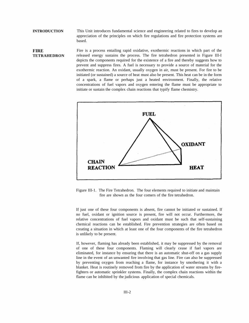
Fire is a process entailing rapid oxidative, exothermic reactions in which part of the
released energy sustains the process. The fire tetrahedron presented in Figure III-I
depicts the components required for the existence of a fire and thereby suggests how to
prevent and suppress fires. A fuel is necessary to provide a source of material for the
exothermic reaction. An oxidant, usually oxygen in air, must be present. For fire to be
initiated (or sustained) a source of heat must also be present. This heat can be in the form
of a spark, a flame or perhaps just a heated environment. Finally, the relative
concentrations of fuel vapors and oxygen entering the flame must be appropriate to
initiate or sustain the complex chain reactions that typify flame chemistry.
Figure III-1. The Fire Tetrahedron. The four elements required to initiate and maintain
fire are shown as the four comers of the fire tetrahedron.
If just one of these four components is absent, fire cannot be initiated or sustained. If
no fuel, oxidant or ignition source is present, fire will not occur. Furthermore, the
relative concentrations of fuel vapors and oxidant must be such that self-sustaining
chemical reactions can be established. Fire prevention strategies are often based on
creating a situation in which at least one of the four components of the fire tetrahedron
is unlikely to be present.
If, however, flaming has already been established, it may be suppressed by the removal
of one of these four components. Flaming will clearly cease if fuel vapors are
eliminated, for instance by ensuring that there is an automatic shut-off on a gas supply
line in the event of an unwanted fire involving that gas line. Fire can also be suppressed
by preventing oxygen from reaching a flame, for instance by smothering it with a
blanket. Heat is routinely removed from fire by the application of water streams by fire
fighters or automatic sprinkler systems. Finally, the complex chain reactions within the
flame can be inhibited by the judicious application of special chemicals.
III-2
FIRE AS A
CHEMICAL
REACTION
As noted earlier, fire is a process entailing rapid oxidative, exothermic reactions in
which part of the released energy sustains the process. In simple terms, fire can be
represented according to the following word equation:
Fuel + Oxidizing Agent Oxidation Products + Heat
If the fuel is a hydrocarbon, CxHY, and the oxidizing agent is oxygen, O2, combustion of
the fuel is described by the chemical equation:
CxHy +(x + y/4)O2 x CO2 + y/2 H2O + ΔHc
This equation assumes complete combustion; that is, the fuel is entirely consumed and
the products of combustion include only carbon dioxide, CO2, water vapor, H2O, plus
heat. The heat released in an oxidative reaction, ΔHc is referred to as the heat of
combustion.
In a fire, water comes off as a vapor, so common use is made of the net heat of
combustion, which automatically accounts for the latent heat of vaporization of water.
For simple fuels, the heat of combustion can be determined directly from basic
thermodynamic parameters (i.e. heats of formation) and the influence of ambient
temperature and pressure conditions can be accounted for.
With more complex fuels (in particular solids), for which the molecular formula may not
be known with precision, the heat of combustion must be measured experimentally. A
common means for measuring heat release during combustion reactions is to combust the
fuel in a pure oxygen atmosphere within an oxygen bomb calorimeter. The concentration
of fuel within the apparatus is adjusted to ensure complete combustion. A table of net
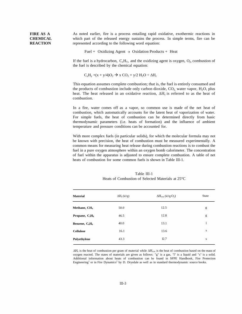
heats of combustion for some common fuels is shown in Table IIl-1.
Table III-1
Heats of Combustion of Selected Materials at 25°C
Material ΔHc (kJ/g) ∆Hcox (kJ/g O2)
Methane, CH4 50.0 12.5
Propane, C3H8 46.5 12.8
Benzene, C6H6 40.0 13.1
Cellulose 16.1 13.6
Polyethylene 43.3 12.7
State
g
g
l
s
s
∆Hc is the heat of combustion per gram of material while ∆Hcox is the heat of combustion based on the mass of
oxygen reacted. The states of materials are given as follows: "g" is a gas, "l" is a liquid and "s" is a solid.
Additional information about heats of combustion can be found in SFPE Handbook, Fire Protection
Engineering1 or in Fire Dynamics2 by D. Drysdale as well as in standard thermodynamic source books.
III-3

The heat liberation in a fire can be related to the amount of oxygen consumed (see Table
III-1). The heat of combustion per gram of oxygen consumed for most organic liquids
is about 12.7 kJ and the heat of combustion per gram of oxygen consumed for most
combustible solids is about 13.0 kJ. These findings can be quite useful in characterizing
heat release when the availability of oxygen is restricted.
The discussion above assumes complete combustion of the fuel. This situation is
generally not the case. The combustion of vapors, liquids and solids in air usually results
in the evolution of some carbon monoxide (CO), soot (mostly carbon, C), and other
chemical species in addition to CO2 and H2O. Visible smoke and the appearance of a
flame can both be attributed to incomplete combustion and, in particular, to the
generation of soot. Moreover, the appearance of a visible flame is due to thermal
radiation emitted by the incandescent soot particles. Well-ventilated flaming combustion
does not generate sufficient CO to be an immediate threat to occupants; however, the less
well ventilated a fire is, the larger the yield of CO and soot.
TYPE OF
FUEL
Vapor
Vapors, liquids or solids can provide the fuel for a flame. However, since flaming
combustion is a gas phase phenomenon, liquids and solids must first be vaporized to
generate vapors for the flame. As the combustion of vapors is common to flames
associated with the burning of vapors liquids and solids, the flaming combustion of
vapors should be discussed first.
Two scenarios exist in which the fuel for flames is in the form of a vapor. If the vapor
and the oxidant are intimately mixed before combustion, the flame is referred to as a
premixed flame. Not all concentrations of vapor in air will ignite. A vapor of a
specified material will ignite with air within upper and lower flammability limits (UFL
and LFL). Above the UFL the mixture is too rich in fuel to sustain combustion and
below the LFL too little fuel is present to maintain heat generation at a level high enough
to sustain the reaction. Because a vapor mixture cannot be ignited if it remains below
its LFL, a common fire prevention measure is to provide adequate mechanical ventilation
in areas where combustible vapors may be present. This measure ensures that the vapor
concentration never reaches the LFL. Tables of UFLs and LFLs are available in the
literature3, 4
.
The LFL of a vapor decreases with increasing temperature, and the UFL increases.
Therefore, as temperature increases, the range in which vapors are flammable also
increases. The LFL is generally insensitive to changes in pressure above atmospheric but
the UFL increases with pressure. The flammability range of a material is therefore
broadened as pressure increases above atmospheric.
A mixture within its flammability limits can be ignited by a small ignition source. This
process is referred to as piloted ignition. Following ignition, a deflagration ensues in
which chemical reactions (and hence a flame) propagate rapidly through the mixture. In
the absence of a localized ignition source (or pilot), a mixture within its flammability
limits will "self-ignite" if heated to temperatures above its auto-ignition temperature.
Again a deflagration follows ignition.
As the deflagration propagates, the temperature of the flame and combustion products is
very high. If the mixture is confined, the pressure also rises rapidly. If no means of
relieving pressure is available, the walls of the confining structure may explode.
III-4
The second type of flame associated with gas phase fuels is a diffusion flame. In a
diffusion flame, the gaseous material and the oxidant come from spatially separated
sources and must mix before combustion can occur. Chemical reaction occurs when the
mixture is between its flammability limits. For small flames, mixing takes place by
molecular diffusion; whereas for larger flames (diameter > 0.5 m), turbulent eddies
cause mixing. Because mixing must occur before combustion begins, the rate of heat
release is slower for diffusion flames than for premixed flames. The usually luminous
flame defines the region where the reaction occurs.
Liquid Fires involving liquids are different from those involving gases because vaporization of
the liquid must occur before fire can begin. The thermodynamic properties of the liquid
(e.g., equilibrium vapor pressure as a function of temperature) as well as the heat and
mass transfer characteristics of the situation determine the potential for combustion. A
liquid can only be ignited by a pilot if its vaporization rate is sufficient to ensure that the
vapor/air mixture at the liquid surface is within the flammability limits of the fuel.
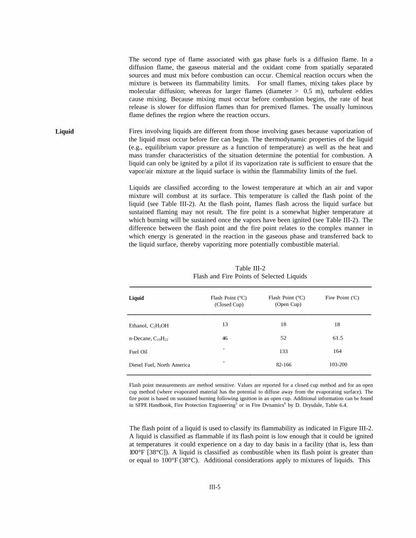
Liquids are classified according to the lowest temperature at which an air and vapor
mixture will combust at its surface. This temperature is called the flash point of the
liquid (see Table III-2). At the flash point, flames flash across the liquid surface but
sustained flaming may not result. The fire point is a somewhat higher temperature at
which burning will be sustained once the vapors have been ignited (see Table III-2). The
difference between the flash point and the fire point relates to the complex manner in
which energy is generated in the reaction in the gaseous phase and transferred back to
the liquid surface, thereby vaporizing more potentially combustible material.
Table III-2
Flash and Fire Points of Selected Liquids
Liquid Flash Point (°C)
(Closed Cup)
Flash Point (°C)
(Open Cup)
Fire Point ('C)
Ethanol, C2H5OH
13
18
18
n-Decane, C10H22 4 6 52 61.5
Fuel Oil - 133 164
Diesel Fuel, North America - 82-166 103-200
Flash point measurements are method sensitive. Values are reported for a closed cup method and for an open
cup method (where evaporated material has the potential to diffuse away from the evaporating surface). The
fire point is based on sustained burning following ignition in an open cup. Additional information can be found
in SFPE Handbook, Fire Protection Engineering5 or in Fire Dvnamics6 by D. Drysdale, Table 6.4.
The flash point of a liquid is used to classify its flammability as indicated in Figure III-2.
A liquid is classified as flammable if its flash point is low enough that it could be ignited
at temperatures it could experience on a day to day basis in a facility (that is, less than
100°F [38°C]). A liquid is classified as combustible when its flash point is greater than
or equal to 100°F (38°C). Additional considerations apply to mixtures of liquids. This
III-5

classification is a convenient way to characterize the fire hazard of a liquid. Fire safety
measures regulating the storage of flammable liquids are very strict, but more leeway is
granted for the storage of combustible liquids if they will not be unduly heated.
Figure III-2. Combustible Liquid Flammability Classification. Classification of a liquid
as flammable or combustible based on OSHA 1910.1067 is shown in this
figure. Flammable liquids (IA, IB and IC) are defined as those with a
closed cup flash point of less than 100°F, whereas combustible liquids (II,
IIIA and IIIB) have a flash point at or above 100°F. Additionally, the
liquid boiling point is used to classify liquids with low flash points (IA and
IB). This classification system is used, for example, to determine the
allowable container type and volume for storage of liquids.
Solid
The mechanisms involved with burning of solids are more varied and more complex than
those for gas phase or liquid fuels. As with liquids, flaming combustion involves
conversion of the solid to a vapor which then becomes involved in the exothermic
reaction that is characteristic of the flame. In addition, some solids can undergo
smoldering in which the solid material is oxidized directly. Our focus is on flaming of
solids.
Combustible solids are generally polymeric (i.e. composed of macromolecules).
Macromolecules are too large to be vaporized directly, so as heat is transferred to a solid
surface from a flame, vapors can only be generated if chemical bonds within the
macromolecules are broken and smaller molecular species are generated. This process
of thermal decomposition (or pyrolysis) requires much more energy than simple
evaporation, which dominates vapor generation for liquids. As a consequence, the
surface temperature of a solid must usually be raised to a much higher level than a liquid
before significant amounts of vapor are released and ignition is achieved. The
temperature at the surface of burning solids is usually > 350°C.
III-6
Some plastic materials, referred to as thermoplastics, melt at a temperature lower than
their ignition temperature. Examples include polyethylene, polypropylene and.
polystyrene. Other materials, referred to as thermosets, do not melt but decompose to
generate vapors and a carbonaceous char. Only thermosets are susceptible to smoldering;
examples include wood, wool and polyurethane. Whether a solid is thermoplastic or
thermosetting depends on its basic molecular structure.
For thermosets, char development on the solid surface may impede heat transfer from the
flame to the unburnt solid material and thereby reduce burning rates. The burning of
wood demonstrates the complexities involved with heat and mass transfer in a
combustible solid. As wood is heated to temperatures around 100°C, water vapor is
driven off. At higher temperatures (200-250°C) the wood begins to discolor as pyrolysis
begins. However, combustible vapors are not generated in sufficient quantity to cause
the wood to be ignited until wood reaches a temperature of 350-390°C. Although the
combustible vapors reach the diffusion flame where reaction generating heat takes place,
the carbonaceous char is left in place. As the wood continues to burn, the pyrolysis zone
recedes deeper into the solid and the char thickens. The char layer insulates the interior
of the wood and thereby impedes the generation of vapors. If not enough combustible
vapor is given off, the flame will cease allowing oxygen to contact the hot char, and
smoldering may begin.
The types and amounts of polymeric materials used in industry, offices, and residences
have increased very rapidly. Many of these materials have unique combustion properties.
Although the combustion of all fuels generates toxic gases, some fuels produce more
toxic substances than others. A wide range also exists in the burning rates of polymeric
materials. An important characteristic of burning rates of liquids and solids is the ratio
of the heat of combustion of the material to the heat required to generate vapors. In
general this ratio is much higher for liquids and hence liquids burn more vigorously than
solids.
To reduce the potential and consequence (hence the risk) of solid fires, fire retardants are
used. Retardant action can range from chemically altering polymeric materials, to
impregnating materials with fire retardant chemicals or to coating the surface of solids
with materials that may interfere with flame spread or pyrolysis. Fire retardant coatings
include paints that expand to form insulating coatings when exposed to fires, impervious
noncombustible materials such as ceramics, coatings that release noncombustible gases
at elevated temperatures and thereby reduce the oxidant concentration surrounding the
solid environment, and cement-like or fibrous coatings that improve the fire-resistance
properties of the composite-solid material.
FLAMING
COMBUSTION
Sustained flaming combustion is a complex, interrelated heat and mass transfer
phenomenon that depends on heat produced through chemical reaction. Figure III-3
depicts a typical flame associated with the burning of a liquid or solid surface. Fuel
vapors generated at the surface are swept into the flame because of buoyant forces.
These buoyant forces also give rise to turbulent eddies that draw fresh air into the flame.
The fuel vapors and oxygen from air mix and undergo chemical reactions. A great deal
of heat is released making the flame hot and buoyant. Products of combustion are
carried upward in the plume rising above the flame. At the same time, some of the heat
released by chemical reactions is transferred back to the liquid or solid surface causing
more fuel vapors to be liberated and the cycle continues.
III-7
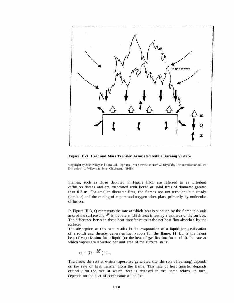
Figure III-3. Heat and Mass Transfer Associated with a Burning Surface.
Copyright by John Wiley and Sons Ltd. Reprinted with permission from D. Drysdale, "An Introduction to Fire
Dynamics" , J. Wiley and Sons, Chichester, (1985).
Flames, such as those depicted in Figure III-3, are referred to as turbulent
diffusion flames and are associated with liquid or solid fires of diameter greater
than 0.3 m. For smaller diameter fires, the flames are not turbulent but steady
(laminar) and the mixing of vapors and oxygen takes place primarily by molecular
diffusion.
In Figure III-3, Q represents the rate at which heat is supplied by the flame to a unit
area of the surface and is the rate at which heat is lost by a unit area of the surface.
The difference between these heat transfer rates is the net heat flux absorbed by the
surface.
The absorption of this heat results in the evaporation of a liquid (or gasification
of a solid) and thereby generates fuel vapors for the flame. I f L v is the latent
heat of vaporization for a liquid (or the heat of gasification for a solid), the rate at
which vapors are liberated per unit area of the surface, m is:
m = (Q - )/ L v
Therefore, the rate at which vapors are generated (i.e. the rate of burning) depends
on the rate of heat transfer from the flame. This rate of heat transfer depends
critically on the rate at which heat is released in the flame which, in turn,
depends on the heat of combustion of the fuel.
III-8

For well-ventilated fires the rate of burning is particularly rapid for materials for which
the heat of combustion is much larger than the heat required to generate gases.
Oxidant Flame chemistry, flame temperature and heat release rates depend on the amount of
oxidant available for the chemical reaction. Poorly ventilated (air starved) flames tend
toward incomplete combustion with both reduced temperatures and heat release rates.
In most fires, oxygen is the oxidizing agent, and it is usually derived from air.
However, halogenated compounds, peroxides, acids, and nitrites (among others) can also
serve as oxidizers in an exothermic reaction with a fuel. Explosives and highly reactive
fuels owe their intense reactivity to the presence of molecular components with oxidizing
capacity within their makeup. The following discussion is restricted to consideration of
air as the oxidizer in combustion processes.
As has been mentioned, in diffusion flames, oxygen and fuel are supplied to the
combustion zone, usually from different directions. Buoyancy (based on temperature
gradients) and physical aspects of the fire scenario play important roles in determining
how oxygen reaches the combustion zone. Flames are not usually stationary, but rather
the reaction zone moves about in a complex manner depending on the availability of both
fuel and oxygen. Flames usually behave in a turbulent manner. A large amount of
oxygen can be entrained into the combustion zone as shown in Figure III-3. The size of
the surface from which fuel is being generated for combustion also plays a role in oxygen
delivery to the reaction interface. If the surface is small, the flames tend to be elongated
and oxygen is supplied to the flame by molecular diffusion through the large flame front
area. At the other extreme, if the surface is large, then the flame will be relatively short
with a relatively smaller flame front area through which oxygen is supplied by turbulent
mixing.
The inability to deliver oxygen to flames emanating from a surface limits the burning rate
of that surface. This situation can be of practical significance in the case of a fire in an
enclosure (i.e. room) that is initially limited by the availability of oxygen through vents
or other openings. If an enclosure fire that is limited by oxygen delivery to the reaction
zone receives sufficient oxygen (for example after windows break) the combustion
reaction will increase dramatically leading to events that increase the severity of the fire.
The dynamics of such fires will be discussed in greater detail in Unit IV.
IGNITION
SOURCES
The common ways fuels are ignited into fires are through piloted ignition, spontaneous
ignition (auto-ignition) or through self heating of the fuel. The first source of ignition
is the most common and can result from flames or sparks. Auto-ignition can result if
materials are externally heated to the auto-ignition temperature causing the material to
burn spontaneously. The last means of ignition discussed is the least likely to occur and
relates to internal heating of the fuel through scenarios such as biological reactivity or
drying.
Ignition of a gas can only occur when the vapor mixture is within the upper and lower
flammability limits (UFL and LFL). Additionally, a minimum ignition energy is required
for combustion to be initiated. For example, simple hydrocarbons require approximately
0.25 mJ to ignite stoichiometric mixtures at 1 atmosphere and 25°C. A typical electrical
spark has about 25 mJ of discharge energy and the static electrical energy generated in
a spark from walking across a rug is approximately 20 mJ 8.
III-9
Because a vapor mixture above its LFL can be ignited easily by electrical sparks, a sound
fire prevention measure is to require only well designed electrical equipment with proper
grounding for use in areas where combustible vapors may collect.
As has been mentioned earlier, the initiation of flaming combustion of a liquid or a solid
fuel is slightly more complex. A flammable vapor/air mixture must first be generated
at the fuel surface by either evaporation (liquid) or gasification (solid). Once the mixture
reaches the LFL an ignition source can initiate flaming combustion as discussed earlier.
REFERENCES
1. Drysdale D [1995). Thermochemistry. In: SFPE handbook of fire protection
engineering. 2nd ed. Ed by DiNenno PJ, Beyler CL, Custer RLP, Walton WD,
Watts JM Jr, Drysdale D and Hall JR Jr. Quincy, MA: National Fire Protection
Association, p. l-83, Chapter 1-5, Table 1-5.3.
2. Drysdale D [1985). Table 1.13. In:An introduction to fire dynamics. Chichester,
UK:John Wiley and Sons, p. 21.
3. Drysdale D [1985]. Table 3.1. In: An introduction.to fire dynamics. Chichester,
UK: John Wiley and Sons, p. 80.
4. Beyler C [1995]. Flammability limits of premixed and diffusion flames. In:SFPE
handbook of fire protection engineering. 2nd ed. Ed by DiNenno PJ, Beyler CL,
Custer RLP, Walton WD, Watts JM Jr, Drysdale D and Hall JR Jr. Quincy, MA:
National Fire Protection Association, p. 2-150, Chapter 2-9, Table 2-9.1.
5. Kanury AM [1995]. Ignition of liquid fuels. In: SFPE handbook of fire protection
engineering. 2nd ed. Ed by DiNenno PJ, Beyler CL, Custer RLP, Walton WD,
Watts JM Jr, Drysdale D and Hall JR Jr. Quincy, MA: National Fire Protection
Association, p. 2-164, Chapter 2-10, Table 2-10.4.
6. Drysdale D [1985]. Table 6.4. In : An introduction to fire dynamics.
Chichester, UK: John Wiley and Sons, p. 197.
7. CPR. Code of Federal regulations. Washington, DC: U.S. Government Printing
Office, Office of the Federal Register.
8. Crowl D, Louvar J [1990]. Chemical process safety: fundamentals with
applications. Englewood Cliffs, NJ: Prentice Hall, p. 201.
III-10
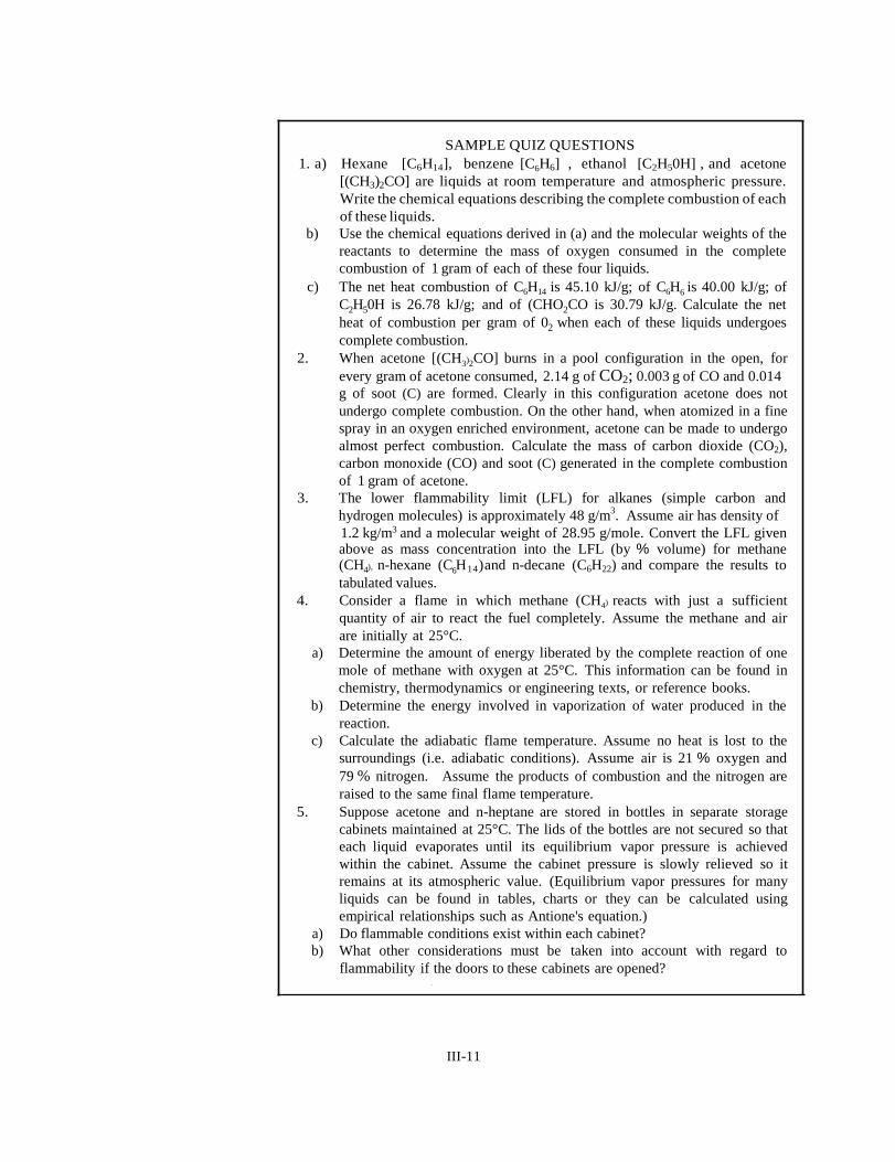
SAMPLE QUIZ QUESTIONS
1. a) Hexane [C6H14], benzene [C6H6] , ethanol [C2H50H] , and acetone
[(CH3)2CO] are liquids at room temperature and atmospheric pressure.
Write the chemical equations describing the complete combustion of each
of these liquids.
b) Use the chemical equations derived in (a) and the molecular weights of the
reactants to determine the mass of oxygen consumed in the complete
combustion of 1 gram of each of these four liquids.
c) The net heat combustion of C6H14 is 45.10 kJ/g; of C6H6 is 40.00 kJ/g; of
C2H50H is 26.78 kJ/g; and of (CHO2CO is 30.79 kJ/g. Calculate the net
heat of combustion per gram of 02 when each of these liquids undergoes
complete combustion.
2. When acetone [(CH3)2CO] burns in a pool configuration in the open, for
every gram of acetone consumed, 2.14 g of CO2; 0.003 g of CO and 0.014
g of soot (C) are formed. Clearly in this configuration acetone does not
undergo complete combustion. On the other hand, when atomized in a fine
spray in an oxygen enriched environment, acetone can be made to undergo
almost perfect combustion. Calculate the mass of carbon dioxide (CO2),
carbon monoxide (CO) and soot (C) generated in the complete combustion
of 1 gram of acetone.
3. The lower flammability limit (LFL) for alkanes (simple carbon and
hydrogen molecules) is approximately 48 g/m3. Assume air has density of
1.2 kg/m3 and a molecular weight of 28.95 g/mole. Convert the LFL given above as mass concentration into the LFL (by % volume) for methane (CH4), n-hexane (C6H14)and n-decane (C6H22) and compare the results to
tabulated values.
4. Consider a flame in which methane (CH4) reacts with just a sufficient
quantity of air to react the fuel completely. Assume the methane and air
are initially at 25°C.
a) Determine the amount of energy liberated by the complete reaction of one
mole of methane with oxygen at 25°C. This information can be found in
chemistry, thermodynamics or engineering texts, or reference books.
b) Determine the energy involved in vaporization of water produced in the
reaction.
c) Calculate the adiabatic flame temperature. Assume no heat is lost to the
surroundings (i.e. adiabatic conditions). Assume air is 21 % oxygen and
79 % nitrogen. Assume the products of combustion and the nitrogen are
raised to the same final flame temperature.
5. Suppose acetone and n-heptane are stored in bottles in separate storage
cabinets maintained at 25°C. The lids of the bottles are not secured so that
each liquid evaporates until its equilibrium vapor pressure is achieved
within the cabinet. Assume the cabinet pressure is slowly relieved so it
remains at its atmospheric value. (Equilibrium vapor pressures for many
liquids can be found in tables, charts or they can be calculated using
empirical relationships such as Antione's equation.)
a) Do flammable conditions exist within each cabinet?
b) What other considerations must be taken into account with regard to
flammability if the doors to these cabinets are opened? .
III-11
Unit IV
DYNAMICS OF FIRE
PURPOSE:
OBJECTIVES:
SPECIAL TERMS:
To familiarize the reader with the determinants of the growth and severity of fire.
To acquaint the reader with:
1. The role of heat transfer in enclosure fires
2. The role of reduced air supply in enclosure fires
3. The stages of fire growth within enclosures
4. Measures of fire severity
5. The threat to life and property
1. Radiant heat transfer
2. Convective heat transfer
3. Conductive heat transfer
4. Entrainment of air
5. Products of combustion
6. Fire growth rates
7. Flame spread
8. Flashover
9. Smoke production
10. Smoke toxicity
IV-1
INTRODUCTION
HEAT TRANSFER
IN FIRES
In Unit III, fundamental scientific and engineering principles were presented to impart
an understanding of the basic characteristics of fire. The impact that an enclosure or
room may have on the course of a fire was not addressed. In this Unit, the relationship
between fire growth and the enclosure within which the fire burns is highlighted.
In fire environments, heat is transferred from regions at high temperature to regions at
lower temperature by the three traditional modes: conduction, convection and radiation.
To understand the dynamics of fire growth within an enclosure, the roles played by each
of these modes in fire-related phenomena must be studied.
Conductive heat
transfer
Convective
heat transfer
Heat transfer by conduction refers to the transfer of heat between solid materials in direct
contact with each other and to the transfer of heat within solid materials1 . (Although heat
conduction also occurs in liquids and gases, its effect is generally masked by convection
in fires.) Conductive heat transfer is governed by the thermal conductivity of a material
and the presence of temperature gradients. For most building elements (excluding steel
and aluminum) heat conduction is a slow process. It can take 20 minutes for the effects of
heating on one side of a 50 mm slab of concrete to become noticeable on the other side.
Solids with low thermal conductivity are considered thermal insulators. For a limited
time, they can be useful for protecting materials that are adversely affected by direct fire
contact. On the other hand, as a consequence of being poor conductors, their surface
temperature rises very quickly when exposed to fire. Hence good thermal insulators that
are combustible are often easy to ignite.
Conductive heat transfer plays a major role in the ignition and spread of a flame over
combustible solids. Conduction is also responsible for the transmission of heat through
building elements, such as floors and walls. Floors and walls that inhibit the transmission
of heat for some time impede the spread of fire to other rooms, and are hence referred
to as fire resistant.
Convection involves the transfer of heat as a result of the movement of a gas (or liquid).
In fire scenarios, the portion of the heat released within flames that is carried away by
the hot products of combustion is referred to as convected heat. Because of buoyant
forces, convection of hot gases usually occurs upward. Convection is the process
whereby fire gases are transported throughout a building and therefore pose risks to
occupants far from a fire.
The term "convective heat transfer" is used in fire safety engineering to denote heat
transfer between a fluid and a solid surface that are at different temperatures2. When a
flame impinges on a solid, heat is transferred by convection from the hot flame to the
cooler solid. On the other hand, if a hot solid is in contact with cool air, heat is
transferred from the solid to the air. In a fire scenario a solid may be heated or cooled
by convective heat transfer.
In fire safety engineering analyses, it is commonly assumed that human survival would
be impossible in a space within a building if the temperature of the air (or smoke) in it
exceeds l20°C. Under such circumstances, convective heat transfer from the hot gas
would cause serious burns to the skin and respiratory systems of humans.
IV-2

Radiative heat
transfer
Hot objects emit thermal radiation in the form of electromagnetic waves, which can travel
across space or through materials3. A significant fraction of the thermal radiation emitted
by flames lies in the infrared region. In Table IV-1, the emissive power of a hot object
or smoky gas is listed as a function of its temperature. Emissive power is the rate at
which radiant energy is emitted per unit surface area of the object. The emissive power
of an object climbs dramatically as it is heated. For hot gases in contact with a solid
object, radiative heat transfer is much greater than convective heat transfer when the gas
temperature exceeds 200-300°C.
Table IV-1
Emissive Power of Hot Objects or Smoke
Temperature (0 C) Emissive Power (kW m-2)
20 200
400
600
800
1000
0.4
2.6
10.5
29.6
67.6
134.0
In small fires, hot products of combustion transport most of the heat released away from
the combustion zone by convection. In larger fires (fuel diameter > 0.3 m), approximately 30% of the heat released is radiated away by soot particles in the flame.
A hot upper layer in a room can emit sufficient radiant energy to cause combustible items
on the floor that are not in direct contact with the flames or hot layer to be heated and
possibly even ignited. In fact, thermal radiation emitted by flames issuing from the
windows of a burning building have caused ignition of combustible elements of
neighboring buildings.
Although a flame has significant emissive power, as one moves further from the flame
the radiant heat impinging on objects decreases. Models are available to calculate the
radiation received by an object remote from a source of known emissive power. Table
IV-2 provides a rough guide to the effects of radiant energy impinging on various
objects4.
Table IV-2
The Effect of Radiant Energy Impinging on Various Objects
Radiation Level (kW. m-2) Effect on Objects
1.0
6.4
10.4
12.5
30.0
Minimal injury for prolonged skin exposure
Pain after 8 second skin exposure
Pain after 3 second skin exposure
Wood can be ignited by a pilot after 15 minute exposure
Most combustibles can be ignited by a pilot after 2 minute exposure
IV-3
ROOM FIRE
DYNAMICS
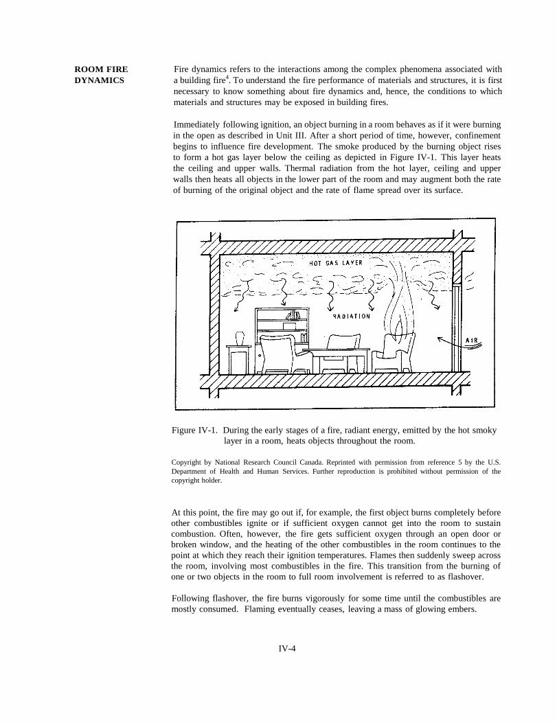
Fire dynamics refers to the interactions among the complex phenomena associated with
a building fire4. To understand the fire performance of materials and structures, it is first
necessary to know something about fire dynamics and, hence, the conditions to which
materials and structures may be exposed in building fires.
Immediately following ignition, an object burning in a room behaves as if it were burning
in the open as described in Unit III. After a short period of time, however, confinement
begins to influence fire development. The smoke produced by the burning object rises
to form a hot gas layer below the ceiling as depicted in Figure IV-1. This layer heats
the ceiling and upper walls. Thermal radiation from the hot layer, ceiling and upper
walls then heats all objects in the lower part of the room and may augment both the rate
of burning of the original object and the rate of flame spread over its surface.
Figure IV-1. During the early stages of a fire, radiant energy, emitted by the hot smoky
layer in a room, heats objects throughout the room.
Copyright by National Research Council Canada. Reprinted with permission from reference 5 by the U.S.
Department of Health and Human Services. Further reproduction is prohibited without permission of the
copyright holder.
At this point, the fire may go out if, for example, the first object burns completely before
other combustibles ignite or if sufficient oxygen cannot get into the room to sustain
combustion. Often, however, the fire gets sufficient oxygen through an open door or
broken window, and the heating of the other combustibles in the room continues to the
point at which they reach their ignition temperatures. Flames then suddenly sweep across
the room, involving most combustibles in the fire. This transition from the burning of
one or two objects in the room to full room involvement is referred to as flashover.
Following flashover, the fire burns vigorously for some time until the combustibles are
mostly consumed. Flaming eventually ceases, leaving a mass of glowing embers.
IV-4

This description of fire growth applies even if the walls and ceiling are noncombustible.
In a different scenario, the preflashover stage may entail ignition of a wall or ceiling.
For example, a fire may start in a wastepaper basket in a comer of a room lined with
combustible wall covering. If the wall is sufficiently flammable, it will catch fire and
flames may spread above the wastepaper basket along the comer. If flames reach the
ceiling and spread along the upper wall, thermal radiation levels at the floor will likely
be sufficient for flashover to occur.
The temperature of the upper gas layer in a room indicates the progression of a room
fire; flashover occurs when the temperature of the upper layer reaches 500 to 600°C.
Figure IV-2 illustrates the three stages of a room fire. The preflashover stage may last
from 5 to 20 minutes, the postflashover stage may last 20 to 40 minutes and the decay
stage for more than an hour. (The dashed curve represents fires in which either the first
item burns out or the fire becomes starved for oxygen before flashover occurs.) In
unsprinklered residential buildings approximately 22 % of fires proceed to flashover5.
Figure IV-2. The course of a room fire is often monitored based on the upper gas layer
temperature in the room.
Copyright by John Wiley and Sons Ltd. Reprinted with permission from D. Drysdale, "An Introduction to Fire Dynamics" , J. Wiley and Sons, Chichester, (1985).
PREFLASHOVER
FIRES
Following ignition and during the early stages of fire growth, occupants have an
opportunity to take action. They may sound the alarm, evacuate the area or begin
suppressing the fire. This opportunity may not last long as conditions within the room
deteriorate rapidly. Occupants unable to leave the room of fire origin will perish before
flashover occurs, usually as a result of severe thermal exposure.
IV-5

Temperatures and heat fluxes that are sufficient to ignite combustible solids are
too extreme for humans to endure. Consequently, slowing down fire growth or
preventing flashover altogether become important fire safety considerations.
In recent years, a great deal of effort has been expended in developing
mathematical models to predict the rate of fire growth in rooms and to assess
whether (and when) flashover occurs6. Such models can also be used to predict the
time available to escape before untenable conditions develop. These models offer
a cost-effective method for analyzing the impact of material selection or building
design on fire safety. A review of such models and a discussion of their strengths,
limitations, and availability has been published recently7.
Fire models have been used to corroborate and to identify the following factors as
significant contributors to preflashover fire growth:
1. The flammability of room contents. The rate at which products release heat as
they burn influences the rate of temperature increase of the hot upper layer
and hence the time needed for untenable conditions and flashover to develop.
2. The distribution of combustibles within the room. If combustible contents are
placed close to one another, fire may spread easily from object to object with
a resultant increase in heat release rate until the upper layer temperature
becomes hot enough that flashover occurs.
3. The flammability of room linings. The rate at which flames spread across the
room linings impacts heat build-up in the room.
4. The thermal properties (thermal conductivity and specific heat) of room
linings. A room lining that is a very good thermal insulator causes heat loss
from the upper layer to be low and the layer's temperature to climb
dramatically, resulting in earlier flashover.
5. The supply of air. In the absence of an open door or window a fire may be smothered in its early stage. Often during a room fire, temperature development is sufficient to break windows and thereby to provide a fresh supply of air.
6. The size and shape of the room. For very large rooms, flashover is an
unlikely event as the large surface area of the walls and ceiling extract heat from
the upper layer very efficiently. Nonetheless, untenable conditions or reduced
visibility may still be experienced early in a fire in a large room.
A number of fire-safety strategies are commonly used to slow down fire growth
or to prevent flashover in a room. Examples include the provision of automatic
sprinklers, restrictions on the flammability of upholstered furniture, requirements
for self-closing doors, and restrictions on the flammability of room lining materials.
A complementary strategy is to provide for efficient occupant response by
providing early fire detection devices and alarms, and by providing adequate
means of egress. Provisions for such strategies are most commonly found in
building codes.
POSTFLASHOVE
R FIRES
Following flashover, a fire generates a great deal of heat and smoke. These can
migrate through the building to threaten the lives of occupants far from the room of
fire origin. Statistics indicate that, in the United States, most fatalities in fires occur
away from the room of fire origin and are the result of smoke inhalation8.
Postflashover fires also pose a threat to compartment boundaries and to structural
elements. Should either of these fail, fire can spread quickly throughout a
building. Consequently, inhibiting fire spread through compartment boundaries
and preventing structural collapse in fire are important fire safety considerations.
IV-6

The severity of a postflashover fire can be quantified in terms of the temperature history
of the compartment gases or in terms of the rate at which toxic products of combustion
are generated. Much research has been conducted to develop mathematical models topredict the severity of postflashover fires
6. These models offer a cost-effective method
for analyzing both the performance of structural elements in the building and the
adequacy of protection provided for escape routes.
Fire models have identified the following factors as contributing most significantly to
postflashover fire severity:
1. The flammability of room contents and interior finish. The rate at which room
contents or interior finish release heat as they burn influences the rate at which the
hot gas temperature rises in the room.
2. The quantity of combustibles. In the absence of suppression activities, the
quantity of combustibles in the room and the rate of fuel consumption determine
the duration of the postflashover stage of the fire. The longer the fire lasts, the
more severe is the attack on structural elements in the room.
3. The thermal properties (thermal conductivity and specific heat) of room linings.
Lining a room with a good thermal insulator causes heat loss from the hot gases
to be low. A room lined with a good insulator experiences a hotter fire than a
room lined with a poor insulator. Consequently, a structural element (such as a
column) in the center of the room lined with a good insulator experiences a more
severe fire than a column in the center of a room lined with a poor insulator.
4. The supply of air (size of openings). Following flashover, windows and doors
that are not fire-rated break or collapse. If the openings are small, the rate of
reaction (and hence rate of heat release) is governed by the rate that air is supplied
and the fire is referred to as ventilation-controlled.
5. The size and shape of the room. In very large rooms, the surface area of the
walls and ceiling are large so a great deal of heat can be extracted from the fire
gases. Therefore, in principle, such fires are not among the hottest. Nonetheless,
because of the sheer volume of flame, they can be difficult to extinguish.
Fortunately, flashover is rare in large rooms.
Several fire safety strategies are commonly used to reduce the impact of postflashover
fires. Examples include the provision of the following: automatic sprinklers; highly fire
resistant room boundaries and structural elements; wired glass; and smoke-control
strategies to deal with the large quantities of smoke generated during a fire. Such
provisions are most commonly found in building codes. A complementary, though less
common strategy is to reduce the quantity of combustibles in rooms.
SMOKE
PRODUCTION
Smoke is defined as the airborne solid and liquid particulates, and fire gases produced
when a material undergoes pyrolysis or combustion. The molecular structure of the fuel
influences the yield of components such as carbon dioxide, carbon monoxide and soot
(carbon) in smoke. For example, for every gram of ethanol consumed in a well
ventilated fire 1.77 grams of CO2, 0.001 grams of CO, and 0.008 grams of soot (carbon)
are generated. On the other hand, for every gram of polystyrene consumed in a well
ventilated fire 2.33 grams of CO2, 0.060 grams of CO, and 0. 164 grams of soot (carbon)
are generated10
.
Smoke may obscure visibility and thereby impede evacuation of a building. It also
represents a toxic hazard to building occupants. (Toxicity is discussed below.)
IV-7
During much of the preflashover stage of a fire, the flames are well-ventilated and
toxicity is generally not a severe problem. Reduced visibility and burns are, however,
serious concerns. Statistics suggest that fatalities associated with preflashover fires are
typically in the room of fire origin and result from burns8.
Postflashover fires are poorly ventilated. The rates of CO and soot generation can be
very high and these products are often transported throughout a building. This may lead
to seriously reduced visibility and the possibility of inhalation of toxic products of
combustion. Statistics suggest that fatalities associated with postflashover fires typically
occur outside the room of fire origin and result from smoke inhalation.8
Smoke toxicity
Toxic fire
gases
A wide variety of fire gases are present in smoke with the toxicants usually
classified as chemical asphyxiants or irritants11
.
Chemical asphyxiants depress the central nervous system, causing loss of
consciousness and ultimately death. Effects of asphyxiants depend on exposure
concentration and duration. Asphyxiants of most concern in fire are carbon
monoxide (CO) and hydrogen cyanide (HCN).
Irritant effects are produced by essentially all fire atmospheres and are of two
major types: (1) sensory (eyes and upper respiratory tract) and (2) pulmonary
(lungs). Sensory effects, which may impede evacuation, are primarily related to the
concentration of the irritant and normally do not increase in severity with time.
Pulmonary irritants may cause lung edema and ultimately death, and are determined
by species concentration and exposure duration.
Extensive investigations of human fire fatalities with respect to exposure to toxic
atmospheres have shown CO to be the primary toxicant. Although CO is not the
most toxic gas at low concentrations, it is always one of the most abundant toxic
gases produced by fires. Recent research has suggested that, for postflashover fires,
the yield of CO may depend not so much on the chemical nature of the fuel as
on the oxygen available for combustion and the thermal conditions in the flames.
Postflashover fires are poorly ventilated and as a general rule, for every gram of
fuel consumed as much as 0.20 grams of CO are generated12
. This is a very high
yield.
HCN is produced from the burning of materials containing nitrogen; for example,
wool and polyurethane. HCN is about 20 times as toxic as CO but is generally
produced in much smaller quantities. Documented cases in which HCN alone is the
primary toxicant are rare.
Fire usually produces carbon dioxide, CO2, in large quantities in fires. Although it is not particularly toxic, it displaces O2 and thereby causes the rate and depth of breathing to increase. This often causes an accelerated inhalation of other toxicants and irritants.
Oxygen, O2, is consumed during a fire. When it drops from its usual level of 21 % in
air to 17%, motor coordination is impaired. When it drops into the 10%-14% range, a
person may exercise faulty judgment and be fatigued quickly. When it drops into the
6%-10% range, a person loses consciousness and must be revived with fresh air or O2
within a few minutes to prevent death.
Acrolein is a potent irritant, both in terms of sensory and pulmonary functions. It
is formed during the smoldering of cellulosics and the pyrolysis of some plastics.
IV-8
Hydrogen chloride (HCl), formed from the combustion of chlorine-containing materials
such as polyvinyl chloride (PVC), is a potent sensory irritant and a strong pulmonary
irritant.
Toxic potency Smoke contains several toxicants. The lethal toxic potency of smoke produced by a
burning material is expressed in terms of its LC50• The LC50 is the concentration that
causes the death of 50% of test rodents within a specified exposure (usually 30 minutes)
and post-exposure time (usually 14 days).
Several small-scale tests have been devised to determine toxic potencies. No single test
is appropriate for all materials under all fire exposures. Unfortunately, small-scale tests
often generate less CO per unit mass of material consumed than that found in real fires.
Thus the LC50 must often be adjusted for use in hazard calculations. Much research is
still required before a validated method is available to predict the toxic hazard in real
world fires on the basis of toxic potencies determined in small-scale tests.
REFERENCES
1. Rockett JA, Milke JA [1995]. Conduction of heat in solids. In: SFPE handbook
of fire protection engineering. 2nd ed. Ed by DiNenno PJ, Beyler CL, Custer
RLP, Walton WD, Watts JM Jr, Drysdale D and Hall JR Jr. Quincy, MA:
National Fire Protection Association, p. 1-25, Chapter 1-3.
2. Atreya A [1995]. Convection heat transfer. In: SFPE handbook of fire protection
engineering. 2nd ed. Ed by DiNenno PJ, Beyler CL, Custer RLP, Walton WD,
Watts JM Jr, Drysdale D and Hall JR Jr. Quincy, MA: National Fire Protection
Association, p. 1-39, Chapter 1-3.
3. Tien CL, Lee KY, Stretton AJ [1995]. Radiation heat transfer. In: SFPE
handbook of fire protection engineering. 2nd ed. Ed by DiNenno PJ, Beyler CL,
Custer RLP, Walton WD, Watts JM Jr, Drysdale D and Hall JR Jr. Quincy, MA:
National Fire Protection Association, p. 1-65, Chapter 1-4.
4. Drysdale D [1985]. An introduction to fire dynamics. Chichester, UK: John Wiley
and Sons.
5. Mehaffey JR [1987]. Flammability of building materials and fire growth. In:
Designing for fire safety: the science and its application to building codes.
Canada: National Research Council Canada, NRCC 28277, pp. 21-33.
6. Walton WD [1995]. Zone computer fire models for enclosures. In: SFPE
handbook of fire protection engineering. 2 nd ed. Ed by DiNenno PJ, Beyler CL,
Custer RLP, Walton WD, Watts JM Jr, Drysdale D and Hall JR Jr. Quincy, MA:
National Fire Protection Association, p. 3-148, Chapter 3-7.
7. Friedman R [1992]. An international survey of computer models for fire and
smoke. J Fire Prot Eng 4:83-92.
8. Hall JR [1996]. Whatever happened to combustion toxicity. NFPA J
Nov-Dec:91-101.
9. Walton WD, Thomas PH [1995]. Estimating temperatures in compartment fires.
In: SFPE handbook of fire protection engineering. 2nd ed. Ed by DiNenno PJ,
Beyler CL, Custer RLP, Walton WD, Watts JM Jr, Drysdale D and Hall JR Jr.
Quincy, MA: National Fire Protection Association, p. 3-134, Chapter 3-6.
10. Tewarson A [1995]. Generation of heat and chemical species in fires. In: SFPE
handbook of fire protection engineering. 2nd ed. Ed by DiNenno PJ, Beyler CL,
Custer RLP, Walton WD, Watts JM Jr, Drysdale D and Hall JR Jr. Quincy, MA:
National Fire Protection Association, p. 3-53, Chapter 3-4.
IV-9

11. Hartzell G [1992]. Combustion products and their effects on life safety. In: Fire
protection handbook. 17th ed. Ed by Cote A and LinvilleJ. Quincy, MA: National
Fire Protection Association, p. 3-3, Chapter 3-1.
12. Babrauskas V [1992]. The generation of CO in bench-scale fire tests and the
prediction for real-scale files. In: Proceedings of the 1st International Fire and
Materials Conference, September 24-25. Ed by Grayson SJ. Washington, DC: pp.
155-178.
SAMPLE QUIZ QUESTIONS 1. Suppose a gasoline spill, that has been contained within a circular dyke of
diameter 2.0 m, is accidentally set on fire. The rate at which heat is
released within the flames is about 6,800 kW. The height of the flames is
about 6.0 m. For gasoline fires, roughly 30% of the total heat released is
radiated away from the flames.
a) Calculate the radiant heat flux (kW m-2
arriving at a point 6.0 m from the
center of the flame. Assume by the time you are 6.0 m away from the
flame that the flame can be pictured as a point source of radiation and that
radiation is emitted uniformly in all directions.
b) Using data presented in Table IV-2, determine whether wood stored 6.0 m
from the flame center will be ignited if the fire is allowed to burn for 15
min or more.
2. Glass typically begins cracking and breaking when exposed to fire gases at
temperature 300°C. Pure aluminium melts at 660°C.
a) Would you expect the glass in windows to break before or after a room fire
experiences flashover?
b) Would you expect the aluminium window frames to melt before or after a
room fire experiences flashover?
3. Consider a short massive wooden column of cross section 300 mm by 300
mm. When exposed in a post-flashover fire, wood typically chars at a rate
of about 0.6 mm/min. Assume that before the fire, the column was loaded
to 1/3 of its ultimate (compressive) strength. As the fire proceeds, the
cross-sectional area of the column is reduced so that its compressive
strength is also reduced. At what point in the fire will the cross-sectional
area of the column have been reduced to 1/3 of its original area so that the
column will fail?
4. A computer monitor containing 1 kg of polypropylene (PP) burns in an
airtight room with dimensions 10 m x 10 m x 3 m. Assume the smoke and
air are mechanically mixed by a fan. Under these conditions, ample air is
in the room to completely burn the PP, and for every gram of PP
consumed, 0.024 grams of CO are generated.
a) Estimate the volumetric fraction of CO in the room. Assume the molecular
weight of a typical air molecule is 28.95. Assume that before the fire, the
air was at temperature 20°C and had density 1.2 kgm-3.
b) Calculate the maximum time occupants can remain in the room without
becoming incapacitated. The time is given by t = 35,000/Vco where t is
time in minutes and Vco is volumetric fraction of CO in ppm (parts per
million).
IV-10

Unit V
PRINCIPLES OF FIRE PROTECTION
PURPOSE:
OBJECTIVES:
SPECIAL TERMS:
To describe the practice of fire protection including the role of codes and standards.
To acquaint the reader with:
1. The scope of fire protection issues
2. Integrated fire safety design
1. Fire Safety Concepts Tree (NFPA 550)
2. Fire safety objectives
3. Fire prevention codes
4. Building codes
5. Compartmentation
6. Structural protection
7. Fire detection
8. Fire suppression
9. Escape routes
V-1

INTRODUCTION
F1RE SAFETY
CONCEPTS TREE
Fire safety
objectives
As mentioned in Unit I, two basic types of codes address fire safety: building codes and
fire prevention codes. Building codes provide a set of fire safety provisions intended to
ensure that an acceptable level of life safety is incorporated into buildings at the time of
their construction. Fire prevention codes spell out a set of provisions intended to ensure
that, following construction, buildings are equipped, operated and maintained to provide
an acceptable level of life safety and property protection from potential hazards created
by fires or explosions. Both building codes and fire prevention codes make reference to
numerous other fire safety codes and standards.
Regulations entail a "hierarchy" of codes and standards. The provision of fire safety can
be viewed as an effort to comply with regulations. Strict adherence to regulations
without an understanding of relationships among fire safety measures and their roles in
meeting fire safety objectives can yield a fragmented approach to design. A facility in
which the escape routes, structural components, alarm system, sprinkler system, smoke
control system, etc. have been designed independently of one another may comply with
regulations, but this arrangement is unlikely to be operationally or economically efficient.
In this Unit, an integrated method for delivering fire safety is presented based on NFPA' s
Fire Safety Concepts Tree (FSCT)1. The FSCT provides a conceptual framework by
which the various fire safety requirements found in regulations work together to achieve
fire safety objectives. Application of the framework can identify options, gaps and
redundancies in fire protection strategies. A discussion of how the FSCT is structured
is presented below, followed by practical examples of its use.
As mentioned in Unit II, when undertaking a fire safety analysis of a facility it must be
clear whether the objective of the analysis is to ensure life safety, property protection,
minimal disruption to business or some combination of these. The uppermost level of
the FSCT depicted in Figure V-1 acknowledges that the ultimate purpose of the exercise
is not just to comply with regulations, but to meet specific fire safety objectives.
Figure V-1. The Fire Safety Concepts Tree identifies two ways to achieve fire safety
objectives: PREVENT FIRE IGNITION or MANAGE FIRE IMPACT.
Reprinted with permission from NFPA 550, Fire Safety Concepts Tree, Copyright c 1995, National Fire
Protection Association, Quincy, MA 02269. This reprinted material is not the complete and official position
of the National Fire Protection Association, on the referenced subject which is represented only by the standard
in its entirety.
V-2

Two strategies are identified in Figure V-1 for achieving fire safety objectives:
PREVENT FIRE IGNITION or MANAGE FIRE IMPACT. These strategies are
connected to the fire safety objectives by an "or gate" (a plus sign within a circle).
Fire safety objectives can be met by preventing ignition or by managing the impact
of fire. To provide an extra measure of security, both strategies are commonly
used.
Prevent fire
ignition The PREVENT FIRE IGNITION branch of the tree (see Figure V-2) includes
measures that are most typically found in fire prevention codes such as NFPA 12.
In general; the branch puts forward provisions related to how facilities are
equipped, operated and maintained following construction.
Figure V-2. PREVENT FIRE IGNITION Branch of the Fire Safety Concepts Tree.
Reprinted with permission from NFPA 550, Fire Safety Concepts Tree, Copyright " 1995, National Fire
Protection Association, Quincy, MA 02269. This reprinted material is not the complete and official position
of the National Fire Protection Association, on the referenced subject which is represented only by the standard
in its entirety.
Suppose that a commercial laboratory proposes to use small quantities of an organic
solvent during chemical analysis tests. The laboratory would like to take appropriate
steps to ensure that the organic solvent is unlikely to be ignited so its use would not pose
an undue risk to laboratory technicians. Figure V-2 presents three strategies to
PREVENT FIRE IGNITION.
1). CONTROL FUEL by the following methods:
a. ELIMINATE FUEL by selecting a nonorganic solvent such as water if such a
choice is compatible with the chemical analysis
b. CONTROL FUEL IGNITABILITY
i. CONTROL FUEL PROPERTIES by choosing the least flammable
organic solvent compatible with the chemical analysis. For example,
V-3
suppose three organic solvents are acceptable for the application: acetone
(C3H6O), benzene (C 6H 6) or monoclorobenzene ( C 6 H 5 C l ) . Acetone
has a flash point of -18°C ,and a boiling point of 56°C, so according to
Figure III-2 it is a Class IB flammable liquid. Benzene has a flash point of
-11°C and a boiling point of 80°C so it is only moderately better than
acetone with respect to its ignitability. Monoclorobenzene which has a
flash point of 32°C and a boiling point of 132°C is a Class IC flammable
liquid and hence it is the least hazardous of the three.
ii. CONTROL THE ENVIRONMENT by carrying out the whole
procedure in a fume hood or in a compartmented area. Fans could remove
the solvent vapors rapidly enough so that the vapor/air mixture always
remains below its lower flammability limit.
2). CONTROL HEAT-ENERGY SOURCES by the following methods:
a. ELIMINATE HEAT-ENERGY SOURCES from the area in which the tests are
conducted. For example, if the most likely ignition source is sparks generated by
electrical equipment, such equipment could be prohibited near the test area.
b. CONTROL RATE OF HEAT RELEASE (or the intensity of electrical sparks)
by choosing properly grounded electrical equipment that has been approved for
areas where combustible vapor/air mixtures may be found.
3). CONTROL SOURCE-FUEL INTERACTIONS by the following methods:
a. CONTROL HEAT-ENERGY SOURCE TRANSPORT
b. CONTROL HEAT-ENERGY TRANSFER PROCESSES
c. CONTROL FUEL TRANSPORT
These strategies are connected through an “and gate” (a dot within a circle). Thus
the decision tree implies that all three strategies must be applied simultaneously
to control source-fuel interactions: Methods to ensure that these three strategies
are achieved are identified in lower levels of the tree (Figure V-2).
At the lowest level of the tree, it is indicated that it may be possible to PROVIDE
SEPARATION between the fuel and ignition sources by ensuring that the solvent
is stored in a cabinet that is isolated from all potential ignition sources.
This example demonstrates how the FSCT can be used to generate several options for
minimizing the fire risk posed by the use of an organic solvent in a commercial
laboratory setting. Many of the provisions developed in this example are specified in the
NFPA's Flammable and Combustible Liquid Code, NFPA 303. ·
Manage fire impact FIRE and MANAGE EXPOSED.
V-4
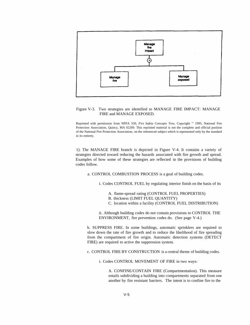
Figure V-3. Two strategies are identified to MANAGE FIRE IMPACT: MANAGE
FIRE and MANAGE EXPOSED.
Reprinted with permission from NFPA 550, Fire Safety Concepts Tree, Copyright "' 1995, National Fire
Protection Association, Quincy, MA 02269. This reprinted material is not the complete and official position
of the National Fire Protection Association, on the referenced subject which is represented only by the standard
in its entirety.
1). The MANAGE FIRE branch is depicted in Figure V-4. It contains a variety of
strategies directed toward reducing the hazards associated with fire growth and spread.
Examples of how some of these strategies are reflected in the provisions of building
codes follow.
a. CONTROL COMBUSTION PROCESS is a goal of building codes.
i. Codes CONTROL FUEL by regulating interior finish on the basis of its
A. flame-spread rating (CONTROL FUEL PROPERTIES)
B. thickness (LIMIT FUEL QUANTITY)
C. location within a facility (CONTROL FUEL DISTRIBUTION)
ii. Although building codes do not contain provisions to CONTROL THE
ENVIRONMENT, fire prevention codes do. (See page V-4.)
b. SUPPRESS FIRE. In some buildings, automatic sprinklers are required to
slow down the rate of fire growth and to reduce the likelihood of fire spreading
from the compartment of fire origin. Automatic detection systems (DETECT
FIRE) are required to active the suppression system.
c. CONTROL FIRE BY CONSTRUCTION is a central theme of building codes.
i. Codes CONTROL MOVEMENT OF FIRE in two ways:
A. CONFINE/CONTAIN FIRE (Compartmentation). This measure
entails subdividing a building into compartments separated from one
another by fire resistant barriers. The intent is to confine fire to the
V-5

compartment of origin and to keep fire from entering escape routes.
B. VENT FIRE. This measure is intended to exhaust the heat and
smoke produced in a fire from the building.
ii. Codes PROVIDE STRUCTURAL STABILITY. Structural fire
protection requirements are intended to prevent collapse of buildings
exposed to fire. In most buildings, structural elements must exhibit
prescribed levels of fire resistance. In addition, in many large buildings,
structural elements must be constructed of noncombustible materials.
Figure V-4. The MANAGE FIRE branch of the FSCT.
Reprinted with permission from NFPA 550, Fire Safety Concepts Tree, Copyright " 1995, National Fire
Protection Association, Quincy. MA 02269. This reprinted material is not the complete and official position
of the National Fire Protection Association, on the referenced subject which is represented only by the standard
in its entirety.
2). The MANAGE EXPOSED branch of the tree shown in Figure V-3 is depicted in
detail in Figure V-5. For applications where life safety is the primary objective, this
branch is particularly important as it contains strategies directed towards protecting
people. Examples are provided below of how these strategies are reflected in building
codes and how more specific details are given in the lower levels of the tree.
V-6
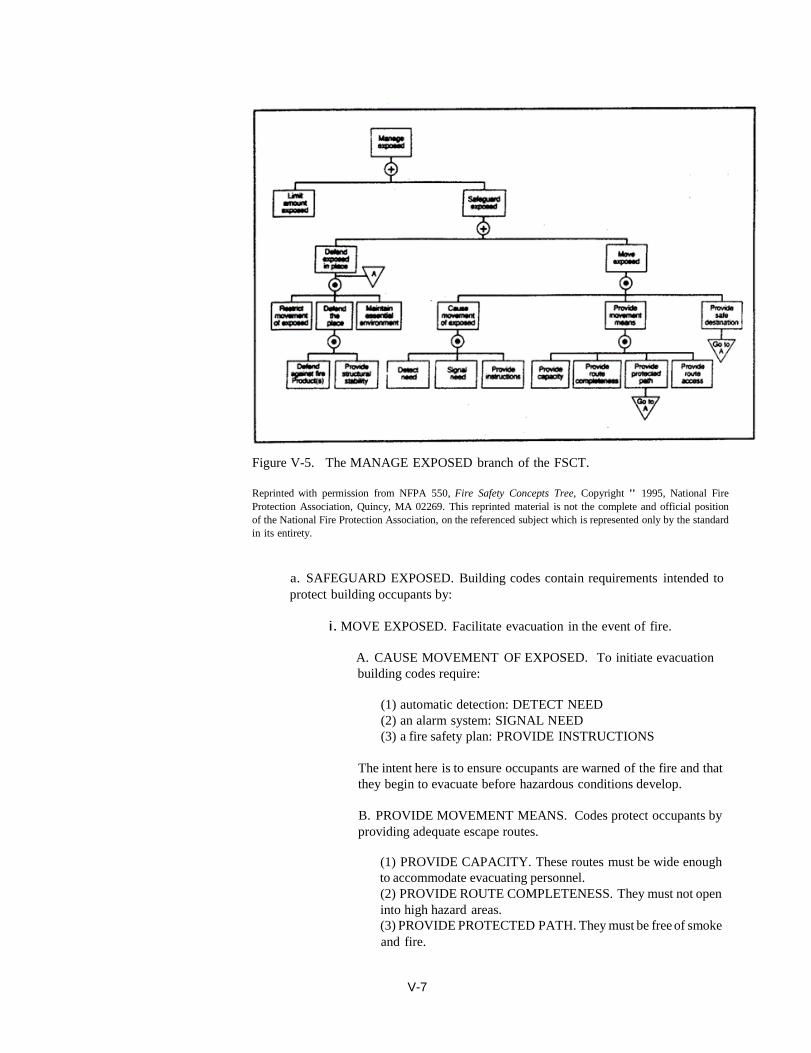
Figure V-5. The MANAGE EXPOSED branch of the FSCT.
Reprinted with permission from NFPA 550, Fire Safety Concepts Tree, Copyright " 1995, National Fire
Protection Association, Quincy, MA 02269. This reprinted material is not the complete and official position
of the National Fire Protection Association, on the referenced subject which is represented only by the standard
in its entirety.
a. SAFEGUARD EXPOSED. Building codes contain requirements intended to
protect building occupants by:
i. MOVE EXPOSED. Facilitate evacuation in the event of fire.
A. CAUSE MOVEMENT OF EXPOSED. To initiate evacuation
building codes require:
(1) automatic detection: DETECT NEED
(2) an alarm system: SIGNAL NEED
(3) a fire safety plan: PROVIDE INSTRUCTIONS
The intent here is to ensure occupants are warned of the fire and that
they begin to evacuate before hazardous conditions develop.
B. PROVIDE MOVEMENT MEANS. Codes protect occupants by
providing adequate escape routes.
(1) PROVIDE CAPACITY. These routes must be wide enough
to accommodate evacuating personnel.
(2) PROVIDE ROUTE COMPLETENESS. They must not open
into high hazard areas.
(3) PROVIDE PROTECTED PATH. They must be free of smoke
and fire.
V-7

(4) PROVIDE ROUTE ACCESS. They must be accessible from
all areas of the building.
The intent is to ensure that occupants have safe routes to evacuate a
building involved in fire.
C. PROVIDE SAFE DESTINATION
ii. DEFEND IN PLACE. For some buildings, such as hospitals,
building codes include requirements that ensure patients are safe from the
effects of fire even if they cannot be moved.
b. LIMIT AMOUNT EXPOSED. Building codes contain requirements that restrict
the number of occupants present in various sections a building to ensure that
escape routes are not overwhelmed.
A discussion of the utility of the FSCT as a design tool follows in the next section.
THE PROVISION
OF FIRE SAFETY
Fire protection engineers commonly address fire (life) safety concerns by demonstrating
compliance with fire prevention and building code requirements. These requirements are
prescriptive and structured to make design and enforcement simple yet effective.
Prescriptive requirements tend to provide detailed descriptions of how to undertake fire
safety design, but they do not spell out the specific objectives of each requirement. The
Fire Safety Concepts Tree provides the fire protection engineer with a simple method for
appreciating how these assorted requirements work together to ensure fire safety.
Information gained from the FSCT may also be used to conceptualize and provide an
overall structure to the design process itself.
As stated in Unit I, codes and standards are being revised to encourage performance
based design in which fire safety is provided by matching the solution to the hazard. The
use of computer software will soon become common to model the spread and severity of
fire in a building as well as the response of building occupants, building components and
fire protection systems. Such developments are opening the door for engineered fire
safety solutions as an alternative to prescriptive solutions. Engineered solutions may
yield more cost-effective and flexible design alternatives than prescriptive solutions.
Clearly, such design can only be undertaken by a well trained fire protection engineer.
The Fire Safety Concept Tree provides a means by which the fire protection engineer can
identify options, gaps and redundancies in alternative fire protection strategies under
consideration.
REFERENCES
1. NFPA [1995]. NFPA 550, Guide to the fire safety concepts tree. Quincy, MA:
National Fire Protection Association, 16 p.
2. NFPA [1992]. NFPA 1, Fire prevention code. Quincy, MA: National Fire
Protection Association, 130 p.
3. NFPA [1993]. NFPA 30, Flammable and combustible liquid code. Quincy, MA:
National Fire Protection Association, 75 p.
V-8
V-9
A building products manufacturer wishes to construct a new 2-storey office
building. The company wishes to use one of its new products as the
interior finish in a small meeting room in the proposed building. This
product is moderately more flammable than building regulations permit. As
currently designed, the room will meet all exiting requirements and will be
equipped with a heat detector as required. The only noncompliant feature
would be the interior finish. Use the Fire Safety Concepts Tree to
recommend other design choices that might yield an equivalent level of
safety as that required by regulations.
Suppose you have been asked to design the fire protection features for a
high-security prison. In the event of fire, you have been told that it is not
feasible to simply allow prisoners the freedom to escape along unsecured
exit routes. Use the MANAGE EXPOSED branch of the Fire Safety
Concepts Tree to devise a strategy which may be used to ensure safety of
prisoners, but without causing a security risk.

Unit VI
FIRE DETECTION
PURPOSE:
OBJECTIVES:
SPECIAL TERMS:
To familiarize the reader with the basics of fire detection.
To present aspects of fire detection including:
1. The theory of detection
2. Compatibility of the detection system with the hazard
1. Fire alarm systems
2. Fire signatures
3. Aerosol detectors
4. Heat detectors
5. Flame detectors
6. Gas sensing detectors
7. Fire alarm code
VI-1
INTRODUCTION
FIRE ALARM
SYSTEMS
DETECTION
DEVICES
Fire signature
The sooner that occupants of a building are warned about the presence of a fire, the more
time they have to escape and take action to protect life or property. Likewise, fire
departments should be notified as quickly as possible so that they can begin their rescue
and suppression activities. As discussed in Unit IV, if a room fire reaches flashover,
evacuation and fire fighting become much more difficult with a higher degree of danger.
In this unit, the basis of fire detection and some general functions of fire alarm systems
are presented. Only general principles are introduced, as a detailed discussion of the
issues related to fire detection and alarm systems is beyond the scope of this module.
Nonetheless, specific references are cited that contain detailed information.
Building codes, occupational standards, insurance carriers, and the specific needs of
building owners may require fire alarm systems to perform diverse functions such as:
1. warning occupants of the presence of a fire
2. alerting fire departments of the presence of a fire
3. indicating the location of a fire by means of a control panel
4. automatically closing fire doors or dampers to ensure good compartmentation
5. automatically closing electrical circuits or gas lines
6. initiating automatic suppression or smoke-control systems
7. activating emergency lighting.
In a large or specialized facility, a fire alarm system may be complex with several basic
components including:
1. detection devices (including manual devices)
2. alarms (these sound within the building but may also communicate remotely with
fire departments)
3. alarm indicating devices to direct the fire services to the location of the fire within
the building
4. a control panel to allow fire services to activate, deactivate or monitor devices
connected to the overall system.
Because of the complexity of fire alarm systems, stringent requirements must be met to
ensure proper design, installation, commissioning, inspection, maintenance and testing
of the entire system.
The sequence of events in fire alarm signaling begins with detection. Therefore,
detection devices must be properly installed, inspected, maintained and tested. Detection
devices must first be selected to be compatible with the anticipated fire hazard; that is,
the selected device must be able to detect the presence of fire before untenable conditions
develop. Detection devices can be categorized according to the "fire signature" that the
device senses.
A "fire signature" is an identifiable change in the local environment caused by a fire.
Examples of fire signatures are the appearance of specific amounts and types of aerosols,
the presence of convected and radiated heat, and the appearance of gases evolved by a
fire. Detection systems are designed to identify one or more of these changes in the
environment. As fires involving different fuels may generate different fire signatures,
a detection device must be chosen to response to the expected hazard (fire). An effective
operational choice of detection devices depends on the expected fire signatures, the
response times of appropriate devices and the minimization (or elimination) of false
alarms.
VI-2

A discussion follows of fire signatures commonly used in detection systems and an
overview of devices used to detect these signatures. Following that is a discussion of
practical considerations associated with operation and maintenance of detection systems.
Aerosol detectors Aerosols include both solid and liquid particulates present in smoke. The size of aerosols
associated with combustion ranges from < 0.001 µm to 10 µm and depends on the
materials being heated, the rate of heating, the agglomeration of small airborne particles,
and the settling characteristics of the aerosols. The range of most aerosols in fires is
between 0.1 µm and 1.0 µm. Size of aerosols plays an important role in the choice of
detection systems. For example, if light scattering is used as a means by which to
measure aerosols, then particles with diameters >0.3 µm would be detected since these
particulates have the ability to scatter light whereas smaller particles are usually referred
to as "invisible" because of their inability to scatter light.
The most common types of aerosol or smoke detectors are based on light obscuration,
light scattering or electrical conductivity of ionized air. These devices are characterized
by rapid detection of aerosols; therefore, they are useful for life-safety concerns.
Light obscuration devices use a light source collimated to fall on a photosensitive device
(see Figure VI-1). The signal detected on the sensing device is reduced when aerosols
interfere with light transmission between the light source and detector. When a preset
level of reduction is sensed, an alarm can be sounded. With these devices, the possibility
exists that dusts as well as products of combustion can cause light intensity reductions at
the sensing device. Light obscuration devices can be contained within a small unit or
they can operate using beams of light projected over large distances.
In light scattering devices used to detect aerosols, the photosensing devices are placed so
that they receive no incident light when no aerosols are present in the air. However,
when aerosols of appropriate size are present, light will be scattered, fall on the
photosensing device, and set off warning systems.
Figure VI-1. Light obscuration detector.
Reprinted with permission from Fire Alarm Signaling Systems, 2nd Ed., Copyright " 1994, National Fire
Protection Association, Quincy, MA 02269 .1
VI-3

Ionization smoke detectors use radioactive materials to ionize the air between electrically
charged electrodes (see Figure VI-2). Ionized molecules of air migrate to the oppositely
charged electrodes thereby creating an electrical current. Aerosols attach to ionized air
molecules slowing their movement with a subsequent diminution of the electrical
conductivity between the electrodes. When the current is reduced below a preset value,
the detection device initiates alarms. New models of ionization smoke detectors have
dual chambers. One chamber is sealed off from the external environment and the other
is exposed to air that may contain products of combustion. The first chamber acts as a
reference and imbalances between the current in the two chambers become the electrical
signal that activates alarms or other devices. Typical application of these detectors is in
areas where fast response is required. However, problems related to dusty conditions or
normal operations such as cooking or industrial operations may interfere with smoke
detection and render this type of device unsuitable.
Figure VI-2. Ionization smoke detector.
Reprinted with permission from Fire Alarm Signaling Systems, 2nd Ed., Copyright " 1994, National Fire
Protection Association, Quincy, MA 02269.1
Heat detectors
Heat detectors are the most frequently used automatic fire detection devices. Typically
they are located under the ceiling in a room and are often the triggering devices for
sprinklers. While heat detectors are generally inexpensive, they rely on convected heat
for activation. Consequently, their response is slower than aerosol detectors. Activation
occurs when a critical component of the device reaches a specific temperature or a
specific rate-of-change of temperature. Fixed temperature heat detectors experience
thermal lag between the environmental temperature and the detector. Even though the
air temperature may have reached a preset value at which device activation is anticipated,
a time delay is associated with heating the detector to that temperature.
The most commonly used heat detector is the soldered link in a levered automatic water
sprinkler as shown in Figure VI-3. As long as the solder remains solid it maintains the
pressurized water in a sealed, nonflow condition. When exposed to high temperatures,
the solder liquefies, the links are no longer held together, the levers that maintain the cap
and gasket arrangement in position are blown away and the pressurized water escapes
VI-4
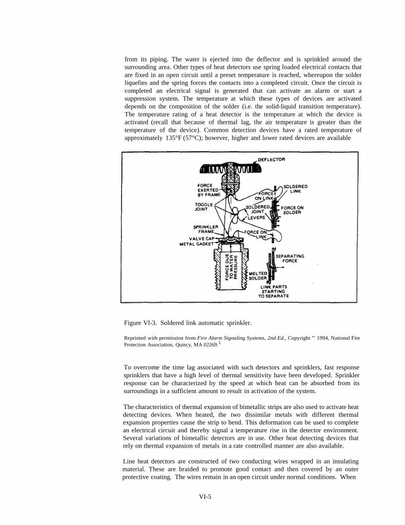
from its piping. The water is ejected into the deflector and is sprinkled around the
surrounding area. Other types of heat detectors use spring loaded electrical contacts that
are fixed in an open circuit until a preset temperature is reached, whereupon the solder
liquefies and the spring forces the contacts into a completed circuit. Once the circuit is
completed an electrical signal is generated that can activate an alarm or start a
suppression system. The temperature at which these types of devices are activated
depends on the composition of the solder (i.e. the solid-liquid transition temperature).
The temperature rating of a heat detector is the temperature at which the device is
activated (recall that because of thermal lag, the air temperature is greater than the
temperature of the device). Common detection devices have a rated temperature of
approximately 135°F (57°C); however, higher and lower rated devices are available
Figure Vl-3. Soldered link automatic sprinkler.
Reprinted with permission from Fire Alarm Signaling Systems, 2nd Ed., Copyright " 1994, National Fire
Protection Association, Quincy, MA 02269.1
To overcome the time lag associated with such detectors and sprinklers, fast response
sprinklers that have a high level of thermal sensitivity have been developed. Sprinkler
response can be characterized by the speed at which heat can be absorbed from its
surroundings in a sufficient amount to result in activation of the system.
The characteristics of thermal expansion of bimetallic strips are also used to activate heat
detecting devices. When heated, the two dissimilar metals with different thermal
expansion properties cause the strip to bend. This deformation can be used to complete
an electrical circuit and thereby signal a temperature rise in the detector environment.
Several variations of bimetallic detectors are in use. Other heat detecting devices that
rely on thermal expansion of metals in a rate controlled manner are also available.
Line heat detectors are constructed of two conducting wires wrapped in an insulating
material. These are braided to promote good contact and then covered by an outer
protective coating. The wires remain in an open circuit under normal conditions. When
VI-5

the temperature around this device is raised, a preset point is reached at which the heat
sensitive insulating material melts allowing the two conducting wires to make contact and
initiate a signal.
To take advantage of the rapid temperature increase associated with flaming fires that
cannot be sensed by these devices, rate-of-temperature rise detectors have been
developed. With these devices, fires can be sensed more rapidly than with devices that
monitor only the absolute value of temperature. Figure VI-4 shows a line rate-of-rise
detector. Under normal conditions and normal fluctuations in temperature, air transfer
through the orifices compensates for expansion of the air in the tubing and air chamber.
However, these orifices are sized so that for temperature rises of approximately 7°C/min,
release of air through these vents is restricted and the volume of the air expands in the
tubing and air chamber. This expansion forces diaphragms to contact and complete an
electrical circuit thereby initiating alarms.
Figure VI-4. Line rate-of-rise heat detector.
Reprinted with permission from Fire Alarm Signaling Systems, 2nd Ed., Copyright " 1994, National Fire
Protection Association, Quincy, MA 02269.1
Using a heat detection device that incorporates more than one of these detection strategies
has become common. A combined fixed temperature and rate-of-rise device is shown
in Figure VI-5. The device senses temperature by deflection of a bimetallic strip and the
rate-of-rise of temperature by the rate of gas expansion in the air chamber. Such devices
can be set to respond to "either" or "and" commands. That is, they can initiate further
VI-6
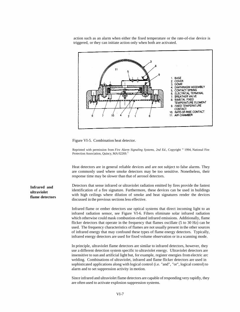
action such as an alarm when either the fixed temperature or the rate-of-rise device is triggered, or they can initiate action only when both are activated.
Figure VI-5. Combination heat detector.
Reprinted with permission from Fire Alarm Signaling Systems, 2nd Ed., Copyright " 1994, National Fire
Protection Association, Quincy, MA 02269.1
Infrared and
ultraviolet
flame detectors
Heat detectors are in general reliable devices and are not subject to false alarms. They
are commonly used where smoke detectors may be too sensitive. Nonetheless, their
response time may be slower than that of aerosol detectors.
Detectors that sense infrared or ultraviolet radiation emitted by fires provide the fastest
identification of a fire signature. Furthermore, these devices can be used in buildings
with high ceilings where dilution of smoke and heat signatures render the devices
discussed in the previous sections less effective.
Infrared flame or ember detectors use optical systems that direct incoming light to an
infrared radiation sensor, see Figure VI-6. Filters eliminate solar infrared radiation
which otherwise could mask combustion-related infrared emissions. Additionally, flame
flicker detectors that operate in the frequency that flames oscillate (5 to 30 Hz) can be
used. The frequency characteristics of flames are not usually present in the other sources
of infrared energy that may confound these types of flame energy detectors. Typically,
infrared energy detectors are used for fixed volume observation or in a scanning mode.
In principle, ultraviolet flame detectors are similar to infrared detectors, however, they
use a different detection system specific to ultraviolet energy. Ultraviolet detectors are
insensitive to sun and artificial light but, for example, register energies from electric arc
welding. Combinations of ultraviolet, infrared and flame flicker detectors are used in
sophisticated applications along with logical control (i.e. "and", "or", logical control) to
alarm and to set suppression activity in motion.
Since infrared and ultraviolet flame detectors are capable of responding very rapidly, they
are often used to activate explosion suppression systems.
VI-7

Figure VI-6. Infrared radiation detector. A light sensitive element attached to a
frequency discriminating device is used to sense infrared radiation.
Reprinted with permission from Fire Alarm Signaling Systems, 2nd Ed., Copyright " 1994, National Fire
Protection Association, Quincy, MA 02269.1
Gas sensing detectors
The equipment developed to sense atmospheric levels of many gaseous contaminants of
air has improved dramatically in recent years, in terms of reliability, the range of
materials that can be sensed, the size of the equipment, and the costs of buying,
installation and using it. Gas sensing detectors are used not only to detect fire signatures
on the basis of the levels of materials usually not found in air, but also to monitor
occupational environments to protect workers from harmful exposures.
Modem construction and office supply materials include a host of different polymeric
materials that, when involved in fire, may produce very hazardous materials. Some of
these products of combustion are fuel specific and thus detection devices can be selected
based on specific gaseous contaminants with specificity for particular locations. For
example, materials such as HCl, HCN, NH3 and oxides of nitrogen may result from
combustion of some polymers. A wide range of sensing mechanisms can be used for
quantitative analysis of specific gases. Several different strategies are used with these
devices with regard to monitoring the air for the presence of these materials (at
appropriate levels to indicate combustion).
These devices may be appropriately used in property protection from fire in a control
room. These gas detection devices are used and tuned to detect low levels of the specific
products of combustion because electronic equipment is susceptible to damage as a result
of exposure to products of combustion of even small or smoldering fires. In this manner,
rapid response with minimal damage is ensured. For this scenario, life safety is served
in two ways: first, early detection warns occupants of the control room, and second,
critical functions directed from the control room are preserved.
VI-8

•
FIRE DETECTION
SYSTEM
CONCERNS
Fire alarm
system
details
As described in OSHA 1910.1642, some concerns are associated with the selection,
installation, maintenance and operation of detection systems. The number, spacing and
location of devices must be in accordance with the nature of the devices. Following
initiation of a signal by a detection device, the device must be restored promptly.
Detection devices must be maintained, tested and adjusted by trained personnel to
maintain proper reliability. Devices must be protected and the response time of a device
should ensure the objectives of its installation.
This unit has presented a general discussion. Details concerning the design, installation,
commissioning, maintenance and testing of fire alarm systems can be found in the
references listed below. NFPA 723 (National Fire Alarm Code) as well as OSHA
1910.1642 and OSHA 1910.169 set the requirements for detection and alarm systems.
In a joint project, NFPA and Society of Fire Protection Engineers have published "Fire
Alarm Signaling Systems" 1 as a resource to help users apply the codes and standards and
to act as a utilitarian guide for basic operational requirements.
REFERENCES
1. Bukowski R, O'Laughlin R, Zimmerman CE [1994]. Fire alarm signaling
systems. 2nd ed. Quincy, MA: National Fire Protection Association, Inc., 430 p.
2. CFR. Code of Federal regulations. Washington, DC: U.S. Government Printing
Office, Office of the Federal Register.
3. NFPA [1993]. NFPA 72, National fire alarm code. Quincy, MA: National Fire
Protection Association, 269 p.
SAMPLE QUIZ QUESTIONS
1. A warehouse, 20 m x 20 m x 6 m (high), has sprinkler heads below the
ceiling on a 4 m square grid. A gasoline fire (diameter 1.2 m) is ignited
equidistant from 4 heads. The nearest heads are immersed in fire gas of
temperature Tg = 109°C and velocity u = 2.53 m s-1 Calculate the time
to activation of the heads assuming t = - RTI u-1/2 ℓn {l – ΔTs/ΔTg}:
where t is time to activation (s); RTI is the response time index of a head
(m1/2s1/2); u is the velocity of the fire gas (m s-1); ∆T, is temperature (above
ambient) at which the head activates (°C); and ΔTg is temperature (above
ambient) of the fire gas. Assume the ambient temperature is 20°C; the RTI
is 150 m1/2·s1 /2 and the activation temperature is 74°C.
2. Flaming combustion of cellulosics (wood, paper, etc.) generates a high
concentration of small smoke particles; whereas smoldering fires produce
a low concentration of large smoke particles.
a) An ionization detector is sensitive to the number of particles in an aerosol
as activation depends on collisions between particles and ions. Is an
ionization detector more sensitive to a flaming or smoldering fire?
b) A photosensitive device is sensitive to the presence of large particles which
scatter much light. Is a photosensitive detector more sensitive to a flaming
or smoldering fire?
VI-9

Unit VII
FIRE SUPPRESSION
PURPOSE:
OBJECTIVES:
S PECIAL TERMS:
To familiarize the reader with the basics of fire suppression.
To present aspects of fire suppression including:
1. The theory of suppression
2. Compatibility of the suppression system with the hazard
1. Water-based suppression
2. Foam-based suppression
3. Chemical-based suppression
4. Automatic suppression systems
5. Fire services
6. Portable fire extinguishers
VII-1
INTRODUCTION
THEORY OF
SUPPRESSION
Water
This Unit presents the issues related to the suppression of fires. Although the term fire
suppression is common and in general is taken to mean checking or stopping a fire, the
techniques described in this Unit may not only suppress a fire, but may often extinguish
it.
This Unit discusses the three major means of suppressing fires: automatic suppression
systems, fire services, and extinguishers. Automatic suppression systems, such as
sprinklers, were originally developed and introduced by the insurance industry more than
a century ago for the purpose of property protection. The design of such systems has
evolved, and they are also now used to achieve life safety objectives.
Unit III introduced the fire tetrahedron and mentioned four mechanisms to suppress a
fire: elimination of oxidant, fuel or heat from the fire zone; and interference with the
combustion chain reaction. The following discussion demonstrates that these four
mechanisms are used often and in combination to suppress fires.
Water is by far the most commonly used fire suppression agent. Although limitations are
associated with the use of water for this purpose, water has many strong advantages. In
addition to its widespread availability and low cost, water has a number of physical
properties that make it a good choice to suppress or extinguish fires.
Water is a stable, relatively dense and inviscid liquid at room temperature and it has
favorable thermal properties for the purposes under consideration here. In particular, the
latent heat of vaporization of water is approximately 2250 kJ/kg at normal conditions.
That is, a large amount of heat is involved in the vaporization of water. If the rate of
heat release from a fire is taken up in vaporization of a noncombustible material such as
water, then the fire can be controlled. If the rate at which heat is absorbed in the
vaporization of water is greater than the fire heat release rate, then the fire is being
extinguished.
The objective in suppressing fires with water is to deliver water to the fire in such a state
that the fire can be quenched by cooling. With its reasonably high surface tension, water
can be delivered as small droplets that improve heat transfer by dramatically increasing
the area of contact between the flame and the mass of water used to suppress the fire.
To aid in the heat transfer process, water is sprayed onto burning surfaces. In addition
to the cooling effect, the conversion of liquid to gas involves a volume increase of about
1,500 times. This rapid expansion in the fire zone serves to exclude air from the fire
thereby smothering it. Although this method is often a secondary effect with respect to
extinguishing fires, it does inhibit continuation of the combustion.
The use of water for fire suppression has some drawbacks. Most important is that water
cannot be left in pipes subject to temperatures at which freezing may occur. This
problem has several solutions: (1) use additives in the water, (2) do not allow the water
to reside in areas where freezing is a possibility, and (3) circulate heated water in the
suppression systems.
Other problems with water relate to: (1) viscosity, (2) surface tension, (3) electrical
conductivity, and (4) density. From one point of view, increasing the viscosity of water
is beneficial because it adheres more easily and forms a thicker covering on solid
materials. However, when viscosity is increased, the pumping requirements for delivery
of water also increases. Wetting agents can be added to water to ensure that it can
penetrate into the interstices of porous materials that may be involved in combustion.
VII-2
Impurities normally found in water render it electrically conductive, and therefore
a potential problem when used to suppress electrical equipment fires. One solution
to this problem is to shut off automatically the power to electric equipment when
water is used to suppress fires. Finally, water should not be used to extinguish
liquid fires in which the combustible material has a density less than that of water
because the lighter liquid will float on the water and continue to burn.
Foams
Some situations involve specialized materials for which water is not the
suppressant of choice. Examples of these are: combustible metals, materials that
react with water and result in hazardous conditions, and gas fires.
Foams are created when air (or some other gas) is trapped because of surface
tension effects in a liquid. Water is the most commonly used liquid in foam
systems. I f water containing additives is mixed with air, a foam may result. With
regard to fire suppression, the additives could be synthetic materials, detergents,
and proteins, among others. Foaming agents are usually added at concentrations of
a few percent. Some foam producing additives are specific for particular
applications. The advantages of using a foam include: increased water surface area
exposed to the combustion material, thicker and more stable coating of suppressant
on a solid surface, and prevention of access of oxidizing agent to the combustion
surface. Foams extinguish fires because of their cooling effect and their ability
to smother the fire. Additionally, foams are of low density and therefore they can
float on liquid surfaces and extinguish fires there. Foams also can suppress vapor
production by completely covering of a liquid surface.
Foams are classified according to their relative volume compared with an equal mass
of water. Low expansion foams occupy up to 20 times the volume of an equal mass
of liquid water while high expansion foams can be generated with up to 1,000 times
the volume of an equal mass of liquid water.
Foams can be produced by several methods including foam induction, proportioning,
and pressure generation. Induction methods involve suction of the foam concentrate
into a flowing stream of water, while the proportioning methods use pumps to
deliver the foaming agent into the water supply. In pressure foam generation, water
and the foaming agent are mixed with air under pressure before delivery to the
discharge nozzle.
Foams are usually not used to flood a large area completely. Foam extinguishing
systems are designed to be used in association with a specified process or material;
that is, foams are usually used in a local application. Hand lines (fire hoses) are
often the method of directing foams to the combustion area.
Aqueous-based foams are electrically conductive and therefore care should be
taken if they are used to suppress fires involving, or in the vicinity of, electrical
equipment. Generally, foams are not recommended for gaseous fires, cryogenic
materials, flowing liquids, and with metals or other materials that react strongly
with water.
Standards associated with the use of foams are NFPA 111 NFPA 11A2
, NFPA 163 and
Carbon
dioxide
OSHA 1910.163.4
Carbon dioxide is used to suppress fires because of its ability to displace the oxidizing
agent from the combustion zone. When the oxygen content of air is reduced from its
normal value of about 21% to below 15%, many fires will not be able to react
sufficiently to sustain combustion. CO2 is usually used in enclosed spaces or for specific
VII-3

area applications. CO2 has an advantage over other means of suppression because it is
not electrically conductive and does not contaminate the area or products within the area of use. As an extinguishing agent, CO2 leaves little residue and is easy to clean up. This
property may be important in industries in which cleanliness is imperative, such as those related to foodstuffs, pharmaceuticals, and computer processing. Details related to the
use of CO2 extinguishing systems can be found in NFPA 125.
Halon
Dry chemicals
AUTOMATIC
SUPPRESSION
SYSTEMS
Automatic water sprinkler systems
Halons are a family of halogenated hydrocarbons, in which some or all of the hydrogen
atoms are replaced by fluorine, chlorine or bromine. The hydrocarbon most commonly
used for this application is methane; however, ethane is sometimes used. These materials
suppress fires by interfering with the combustion reaction. Unfortunately, these very
effective fire suppression agents have deleterious effects on the environment (destruction
of the ozone layer) and they are toxic to humans in high concentrations. The use of
halons is being phased out. The fire suppression industry is working to find replacements
for halons. Halon fire extinguishing systems are discussed in NFPA 12A.6
Powders of dry chemicals when sprayed on a fire can suppress combustion. The
materials typically used in this application are: sodium, potassium or urea-potassium
bicarbonates as well as potassium chloride or mono-ammonium phosphate. Although
these materials may smother the fire, exert a cooling effect, or even reduce radiation to
the fuel, the primary action of these fire suppression materials is believed to be their
ability to interfere with the combustion reaction required to sustain the fire. These
materials are notorious for the rapidity with which they can extinguish fires.
Dry chemical can be used to suppress fires in both a total system flooding mode or local
application. These materials are basically nontoxic and can be used for electrical fires.
Their primary use is associated with fire suppression of flammable liquids. Additives are
sometimes used to improve the storage and handling properties of these dry materials.
NFPA 177 describes the use of dry chemicals in extinguishing systems.
Automatic suppression systems are often used to ensure rapid application of suppression
agents in the event of fire. The earlier fire suppression commences the less likely it is
that there will be loss of life or serious property damage. Several automatic suppression
systems are described in the next sections.
Automatic water sprinkler systems are cost effective and are the most widely used
automatic fire suppression systems. In addition to the numerous standards involved with
sprinkler systems (most notably the relevant sections of NFPA 138 and OSHA Standards
1910.15514, 1910.1604, and 1910.1634), several specific references (e.g. Solomon 19949)
and general references (e.g. SFPE Handbook 199510 Fire Protection Handbook 1992u)
serve as resource materials for the design, engineering and testing of these systems.
The basic elements of an automatic water sprinkler system are as follows:
1. a detection system that is either part of the sprinklers or an entirely separate
system,
2. a control unit that responds to the detection system,
3. a water supply that meets the requirements of the suppression system; these
include adequate volume and pressure as well as reliability,
4. hydraulically designed piping system that is compatible with the water supply and
that can deliver a specified amount of water when sprinklers are activated,
5. sprinkler heads with rated discharges positioned in appropriate areas and numbers
to suppress fire. If the sprinklers heads are open, a separate detection system
VII-4

must be used to actuate water flow. If the sprinkler heads have closed orifices,
which is more common, the heads open automatically when fire is detected by the
heads (i.e., the links open).
6. an automatic alarm system that can warn people in the area that the sprinkler
system is activated and water flow has begun to suppress the fire.
In addition to these considerations, automatic sprinkler system design includes false alarm
protection devices, shut-off valves (usually at the point of entry into the building),
external alarming, water removal capabilities, the potential for auxiliary action (e.g. door
closure, shut-off of specified electrical services including process equipment and exhaust
fans) and a manual means of initiating the system.
Wet pipe water sprinkler systems use automatic sprinklers (discussed briefly in Unit VI)
attached to a piping system full of water that is connected to the water supply. When the
sprinklers detect heat from the fire and open, water is discharged in the area of detection.
Dry pipe systems operate in a similar fashion except that the piping system contains
pressurized gas (air or nitrogen). When a sprinkler detects a fire, it opens and this
pressurized gas is released which actuates a valve allowing water to flow into the piping
system and through the sprinklers. This type of system has an obvious advantage over
the wet pipe system when the possibility exists of water freezing in the piping system.
Preaction systems can contain air (not necessarily under pressure) in the piping system
but also have additional detection devices in the areas covered by the sprinklers. When
these detection devices are activated, water is permitted to flow into the piping system
and through any sprinklers that are open.
A deluge system has open sprinklers and a detection system that controls the water
supply. When activated, water is permitted to flow and be discharged through the open
sprinklers.
Sprinklers come in a variety of types including, as mentioned earlier, those with and
without detection capabilities. Sprinklers can be mounted in rooms either from the
ceiling (upright sprinklers are intended for use in the upright position, while pendent
sprinklers are installed under water supply pipes) or walls (sidewall sprinklers). They
can be concealed or exposed. Considerable engineering efforts have gone into
development of sprinklers so that patterns of discharge of water as well as the amount
of water delivered are sufficient for suppression. For further details concerning the types
of calculations required to meet suppression needs, the reader is directed to the references
cited in this unit.
Dry pipe sprinkler systems considerations are similar to those described earlier.
Although these systems can be used in areas where freezing may be a problem, they have
an additional time delay associated with the delivery of water compared with wet pipe
systems. The manner in which the control valves operate also requires considerations
different from those needed for wet pipe systems. Regardless of which type of system
is used, periodic testing is required to ensure that the water supply and the remainder of
the automatic sprinkler system can operate as intended.
Foam extinguishing
systems
Most of the same general considerations as described earlier apply to automatic foam
extinguishing systems that generate foam at the time of use. Because of the nature of
foams and how they are formed from water and the foaming agent, care must be taken
VII-5

to ensure that the mechanisms associated with generating the foam are not compromised
during a fire. Additionally, nozzles that are specific to foams are required for proper
delivery of the foam to the fire. In some applications, foams are used to cover
completely a liquid surface that is engulfed in flames. Under these circumstances the
foam is sometimes applied from the edges of the liquid container from where the foam
spreads across the entire liquid surface. Specific details about standards for foam
extinguishing systems can be found in various sections of NFPA 111 and 163 as well as
in OSHA 1910.163.4
Carbon dioxide
systems
Halon extinguishing
systems
Dry chemical
systems
SUPP RESSION BY
THE FIRE
SERVICES
In-house fire
brigades
Carbon dioxide extinguishing systems can be used to flood an area totally, but they are
usually used for relatively small enclosed areas or for a local application, particularly for
gas fires. NFPA 125 and OSHA 1910.1624 contain the standards relevant to the use of
CO2 extinguishing systems. In the event of a gas fire, the supply of gas should be shut off
automatically once the fire is detected and the CO2 extinguishing system is activated.
With regard to fire in an enclosure in which humans are not present, room openings such
as vents, windows and doors should be closed automatically so that the CO2 can be
effective in reducing the oxygen content near the fire. In addition to the extinguishing
system components, storage of the CO2 must be considered. Piping design, discharge
nozzles and valves, and other operating devices are specific to the use of this agent,
which is usually stored as a liquid under pressure. This latter condition creates the
potential for safety hazards.
Many of the same considerations for the use of CO2 also apply for halon. This material,
which is usually a gas at normal conditions, is also stored under pressure as a liquid
when used as an extinguishing agent. Standards covering halon extinguishing systems
can be found in the subsections of NFPA 125 or OSHA 1910.162.4 A high level of noise
as well as fogging or clouding is usually associated with discharge of halons. In addition,
special piping system design is required. However, the use of halons is being phased out
and materials with similar properties as halons are being researched.
Dry chemical extinguishing systems deliver solid materials to suppress the fire. The solid
materials are usually in the form of a powder that can be propelled to the fire by
pressurized gas. The solids and gas (usually nitrogen) can be premixed or mixed from
separate containers as they are expelled onto the fire. Additives are often used to ensure
that no clumping occurs and that the solid entrainment and delivery via a pressurized gas
proceeds smoothly. Specialized piping designs, nozzles and_ control systems are required
for the two-phase flow form of fire suppression. The relevant standards are NFPA 177
and OSHA 1910.1614
Fire services can include both in-house fire brigades and public fire departments. No
simple formula exists for both the determination of the need for in-house services and for
the specific interaction and distribution of responsibilities between local facility services
and the public services. A need exists for a local emergency plan that may involve
various levels of government.
If a facility-specific fire brigade is required, then a number of issues related to its
effective operation must be addressed. Individuals must be selected and trained for duties
in the fire brigade. Their education should be both wide ranging with regard to fire
suppression and specific concerning the probable nature of fire suppression at that
facility. The members of the brigade must be physically fit and trained in the proper use
of fire fighting equipment. Additionally, they must have proper personal protective
equipment including proper respirators for the situations that they may encounter.
VIl-6
Services must be secured that relate to fire protection, such as the availability of water
supplies and access to all sites. An emergency action plan and pre-fire planning is
required. These may involve risk management studies and must include information
describing building occupancy, construction and contents. The fire protection features
of the building or areas must be known including the location and availability of water
supplies. Unusual environmental features that may affect fire fighting must be
considered. The fire brigade must know the facility so that critical concerns relating to
the spread of the fire can be identified. Pre-fire fighting plans must involve other fire
fighting agencies, who may be called on to cooperate. To assist in suppression activities,
information relating to materials and equipment on site must be pre-recorded in special
forms to avoid delays in decisions concerning fire fighting procedures.
Public fire
departments
PORTABLE FIRE
EXTINGUISHERS
The size and capabilities of public fire departments vary significantly depending on
location (city versus rural) and population. As described earlier, an in-house fire brigade
must devise plans with local fire authorities to ensure effective fire suppression. In the
absence of a facility-run brigade, open communications should be maintained with local
fire departments who would be summoned via the fire alarm system at the industrial site.
Pre-fire planning would ensure compatibility between public equipment and site services
(e.g. water main connections), and inform the public fire fighting agency of the materials
and equipment that are likely to be involved in a fire. In this spirit of cooperation, public
fire department personnel would be notified beforehand of procedures that must be used
in fighting specific fires. Additionally, they would be aware of hazardous conditions
associated with those fires. These issues may be critical if the public fire fighters are not
pre-trained in specific industrial fire fighting techniques. Also, the response times and
the expected levels of support from the public agencies can be anticipated; both of these
concerns can have a significant influence on how suppression of a fire is managed.
Portable fire extinguishers are mandatory in all buildings, except residences, and are
intended for use in the early stage of fire development. Persons using these devices
should be trained. A critical feature of these devices is that they have a limited capacity.
Suppression agents discussed in automatic sprinkler systems are also used in portable fire
extinguishers. Fire extinguishers must be suitable for the class of fire that they are used
to suppress. Fires are characterized into the following classes based on the burning
material, see also Figure VII-1:
Class A: common solid materials including wood, paper, some plastics and textiles.
Class B: liquids or solids that produce combustible liquids when involved in fire.
Class C: Class A or Class B materials with the involvement of electrical equipment.
Class D: combustible metals.
Considerations for selection, placement, and use of portable fire extinguishers include:
1. symbols (and color coding) fixed to extinguishers designating the type (or types)
of fires that the extinguisher can be used on,
2. a designation of the rating of the extinguisher (i.e. a reference to the volume or
applicable area for the extinguishing material; these designations are not available
for all extinguishers),
3. distribution of extinguishers based on the hazard classification of the area to be
protected (more than one type of extinguisher may be appropriate),
4. maximum travel distance of the extinguishing material for Class B fires,
fires, extinguishers
5. inspection, maintenance, and testing of fire extinguishers, and
6. training and education programs.
VII-7

Figure VII-1 Fire extinguisher classification labels. Geometric and lettered labels are
shown. When color coded, Class A fire extinguishers have green labels,
Class B - red labels, Class C - blue labels and Class D - yellow labels.
Reprinted with permission from NFPA 10, Portable Fire Extinguishers, Copyright " 1994, National Fire
Protection Association, Quincy, MA 02269. This reprinted material is not the complete and official position
of the National Fire Protection Association, on the referenced subject which is represented only by the standard
in its entirety.
Water based
extinguishers
Standards for portable fire extinguishers are found in NFPA 1012 and OSHA 1910.1574 •
Water-based extinguishers intended for use on Class A fires are the most common type.
A schematic of a pressurized water extinguisher is shown in Figure VII-2. In addition
to water, other materials such as antifreeze may be added. A pressure gauge can be
viewed to ensure that the unit is operational. In general the 2 to 2.5 gal units weighing
approximately 30 lb are charged to approximately 100 psi and are capable of discharging
water to a distance of about 30 ft for a period of 1 min. These fire extinguishers can be
recharged. To use this unit, a ring pin placed through the handle must be removed. The
nozzle is then directed toward the fire and the levers are squeezed.
Figure VII-2 A pressurized water fire extinguisher.
Reprinted with permission from NFPA IO, Portable Fire Extinguishers, Copyright " 1994, National Fire
Protection Association, Quincy, MA 02269. This reprinted material is not the complete and official position
of the National Fire Protection Association, on the referenced subject which is represented only by the standard
in its entirety.
VII-8
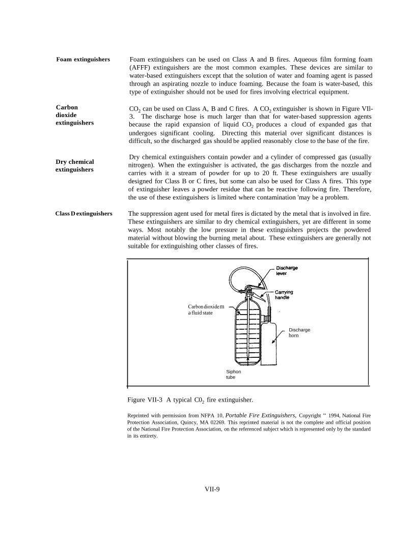
a fluid state
Discharge
horn
Siphon tube
Foam extinguishers
Carbon
dioxide
extinguishers
Dry chemical
extinguishers
Foam extinguishers can be used on Class A and B fires. Aqueous film forming foam
(AFFF) extinguishers are the most common examples. These devices are similar to
water-based extinguishers except that the solution of water and foaming agent is passed
through an aspirating nozzle to induce foaming. Because the foam is water-based, this
type of extinguisher should not be used for fires involving electrical equipment.
CO2 can be used on Class A, B and C fires. A CO2 extinguisher is shown in Figure VIl-
3. The discharge hose is much larger than that for water-based suppression agents
because the rapid expansion of liquid CO2 produces a cloud of expanded gas that
undergoes significant cooling. Directing this material over significant distances is
difficult, so the discharged gas should be applied reasonably close to the base of the fire.
Dry chemical extinguishers contain powder and a cylinder of compressed gas (usually
nitrogen). When the extinguisher is activated, the gas discharges from the nozzle and
carries with it a stream of powder for up to 20 ft. These extinguishers are usually
designed for Class B or C fires, but some can also be used for Class A fires. This type
of extinguisher leaves a powder residue that can be reactive following fire. Therefore,
the use of these extinguishers is limited where contamination 'may be a problem.
Class D extinguishers The suppression agent used for metal fires is dictated by the metal that is involved in fire.
These extinguishers are similar to dry chemical extinguishers, yet are different in some
ways. Most notably the low pressure in these extinguishers projects the powdered
material without blowing the burning metal about. These extinguishers are generally not
suitable for extinguishing other classes of fires.
Figure VII-3 A typical C02 fire extinguisher.
Reprinted with permission from NFPA 10, Portable Fire Extinguishers, Copyright " 1994, National Fire
Protection Association, Quincy, MA 02269. This reprinted material is not the complete and official position
of the National Fire Protection Association, on the referenced subject which is represented only by the standard
in its entirety.
VII-9
REFERENCES 1. NFPA [1994]. NFPA 11, Standards for low expansion foam and combined agent
systems. Quincy, MA: National Fire Protection Association, 51 p.
2. NFPA (1994]. NFPA llA, Standards for medium and high expansion foam
systems. Quincy, MA: National Fire Protection Association, 23 p.
3. NFPA [1995]. NFPA 16, Standard on deluge foam-water sprinkler and foam
water spray systems. Quincy, MA: National Fire Protection Association, 20 p.
4. Code of Federal Regulations (CFR) Title 29, Part 1910 [1997]. Washington, DC:
U.S. Government Printing Office, Office of the Federal Register.
5. NFPA (1993]. NFPA 12, Standards for carbon dioxide extinguishing systems.
Quincy, MA: National Fire Protection Association, 46 p.
6. NFPA [1992]. NFPA 12A, Standards for halon 1301 fire extinguishing agent
systems. Quincy, MA: National Fire Protection Association, 64 p.
7. NFPA [1994]. NFPA 17, Standard for dry chemical extinguishing systems.
Quincy, MA: National Fire Protection Association, 22 p.
8. NFPA [1994]. NFPA 13, Standards for the installation of sprinkler systems.
Quincy, MA: National Fire Protection Association, 124 p.
9. Solomon R, ed. [1994]. Automatic sprinkler systems handbook. 6th ed. Quincy,
MA: National Fire Protection Association, 790 p.
10. Fleming RP [1995]. Automatic sprinkler calculations. In: SFPE handbook of fire
protection engineering. 2nd ed. Ed by DiNenno PJ, Beyler CL, Custer RLP,
Walton WD, Watts JM Jr, Drysdale D and Hall JR Jr. Quincy, MA: National
Fire Protection Association, p. 4-56, Chapter 4-3.
11. Cote A, Linville J, eds. [1992]. Fire protection handbook. 17th ed. Quincy, MA:
National Fire Protection Association.
12. NFPA [1994]. NFPA 10, Standards for portable fire extinguishers. Quincy, MA:
National Fire Protection Association, 50 p.
VII-10
SAMPLE QUIZ QUESTIONS
a) A post-flashover fire is burning in a room. The window (width w =2.0 m:
height h = l.5 m) is broken but the door to the inside of the building is
closed and intact. The fire is ventilation-controlled and the rate at which
heat is released by the fire can be approximated as Q = 1100 w h3/2 {where
Q is in kW, and w and h are in m}. Calculate the rate at which heat is
released in the fire.
b) Suppose that water mist is applied to the fire. At what rate (ℒ /min) must
the mist be applied to absorb the heat being released by the fire? Assume
perfect efficiency; that is, the rate of heat release = rate of heat absorption
by water with no excess water mist applied. Assume the mist starts as
liquid droplets at 20°C. Account for the energy required to heat the
droplets to l00°C and then vaporize them to steam at 100°C. Assume the
density of water is 1000 kg/m3, the specific heat of water in the range 20-
100°C is 4.182 x 10³ (kg °C) and the heat of vaporization or water is
2.26 x 10⁶ J/kg.
Suppose 1 kg of water is sprayed on a fire and is vaporized to form water
vapor at temperature 100°C. Use the ideal gas law to compute the resultant
increase in volume of the vapor compared to the original water.

GLOSSARY
AEROSOL: the liquid and solid particulates in smoke.
AEROSOL DETECTOR: a detector designed to be
activated by the liquid and solid particulates in
smoke.
AUTO-IGNITION TEMPERATURE: the lowest
temperature at which a vapor/air mixture
within its flammability limits can undergo
spontaneous ignition.
AUTOMATIC SUPPRESSION SYSTEM: a fire
suppression system that activates upon
detection of a fire without the need for human
intervention.
BUILDING CODE: a set of requirements intended
to ensure that an acceptable level of safety
(including fire safety) is incorporated into a
building at the time of construction.
BUILDING SERVICES: provisions, such as
heating, plumbing, electrical and air handling
systems, that render a building habitable.
CHEMICAL ASPHYXIANTS: toxicants that
depress the central nervous system causing
loss of unconsciousness and ultimately death.
CLASS A FIRE: fire involving common solids such
as wood, paper, and some plastics and
textiles.
CLASS B FIRE: fire involving liquids or solids
(such as thermoplastics) that produce
combustible liquids when they burn. ·
CLASS C FIRE: fire involving Class A or Class B
materials as well as electrical equipment.
CLASS D FIRE: fire involving combustible metals.
CODE: comprehensive set of requirements intended to
address fire safety in a facility. Codes may
reference numerous standards.
COMBUSTIBLE LIQUID: a liquid with flash point
equal to or greater than l00°F (38°C).
COMPARTMENTATION: a fire protection
strategy whereby a building is subdivided
into compartments that are separated from
one another by fire resistant barriers.
CONDUCTIVE HEAT TRANSFER: the transfer of
heat within solid materials or between solid
materials in contact.
CONVECTED HEAT: the portion of heat released
in a fire that is carried away by the hot
products of combustion.
CONVECTIVE HEAT TRANSFER: the transfer of
heat between a gas and a solid surface at
different temperatures.
DEFLAGRATION: the rapid propagation of a flame
through a vapor/air mixture following
ignition.
DIFFUSION FLAME: a flame for which
combustible vapor and oxidant come from
spatially separated sources and must mix
before combustion can occur.
EMISSIVE POWER: the rate at which radiant
energy is emitted by unit surface area of an
object.
EXTINGUISH: completely put out a fire.
FIRE: a process entailing rapid oxidative, exothermic
reactions in which part of the released energy
sustains the process.
FIRE ALARM SYSTEM: fire protection equipment
that can detect a fire, warn occupants, alert
the fire department and initiate other fire
protection activities such as automatic
suppression, smoke control, etc.
VIII-1
FIRE DYNAMICS: the interaction among the
complex phenomena involved in a building
fire.
FIRE FIGHTING FOAM: a fire fighting medium
that is created by adding a foaming agent to a
liquid (usually water).
FIRE PERFORMANCE: the response of a material
or product to a source of heat or flame
under controlled fire conditions. Fire
performance includes: ease of ignition,
flame spread, smoke generation, fire
resistance and toxicity of smoke.
FIRE POINT: the lowest temperature at which
flaming can be sustained at the liquid's
surface.
FIRE PREVENTION CODE: a set of requirements
intended to ensure that, following
construction, buildings are equipped, operated
and maintained to provide an acceptable level
of protection from potential hazards created by
fires or explosions.
FIRE RESISTANCE: ability of a building assembly
to withstand the passage of flame and the
transmission of excessive heat, and to stay in
place when exposed to fire.
FIRE SAFETY CONCEPTS TREE: a decision tree
that depicts how various fire safety strategies
can work together to achieve fire safety
objectives.
FIRE SIGNATURE: a property of fire (temperature,
smoke concentration, etc.) that is used to
detect the presence of fire.
FIRE SUPPRESSION: action taken with the intend
to control the growth of a fire.
FIRE TETRAHEDRON: a schematic
representation of fire in which the four
elements required to initiate and maintain
fire (fuel, oxidant, heat and chain reactions)
are depicted as the four comers of a
tetrahedron.
FLAME DETECTOR: a detector that is activated
by electromagnetic radiation emitted by
flames.
FLAME-SPREAD RATING: a measure of the
flame-spreading propensity of a material.
FLAMMABLE LIQUID: a liquid whose flash
point is less than l00°F (38°C).
FLASHOVER: the very sudden transition from the
burning of a few objects in a room to full
involvement of all combustibles in the room.
FLASH POINT: the lowest temperature at which
flames will flash across a liquid's surface.
The measurement of a flash point is usually
done in a loosely sealed vessel referred to as
a closed cup.
GAS SENSING DETECTOR: a detector that
activates when a critical concentration of some
gaseous product of combustion is reached.
HALON: a hydrocarbon in which some or all of the
hydrogen atoms are replaced by fluorine,
chlorine or bromine atoms.
HEAT DETECTOR: a detector that activates when
its sensing element reaches a critical
temperature or rate-of-rise of temperature.
HEAT OF COMBUSTION: the heat released when
a combustible material undergoes complete
combustion.
HEAT TRANSFER: the flow of heat from regions
of high temperatures to regions of low
temperature.
IRRITANTS: toxicants that irritate the eyes, upper
respiratory tract and/or lungs.
LOWER FLAMMABILITY LIMIT: the lowest
concentration of a vapor/air mixture which
can be ignited by a pilot.
PERFORMANCE-BASED REQUIREMENTS: codes
and standards that require design solutions be
engineered to address the expected hazard in
such a fashion that an acceptable level of
safety (performance) is ensured.
VIII-2
PILOTED IGNITION: ignition of a vapor/air mixture
by a small ignition source.
PLUME: the column of smoke which, due to
buoyancy, rises above a fire.
PREMIXED FLAME: a flame for which combustible
vapor and oxidant are well mixed before
combustion occurs.
PRESCRIPTIVE REQUIREMENTS: detailed and
often rigid measures mandated in codes and
standards as the means to ensure fire safety.
RADIATIVE HEAT TRANSFER: the emission (by
hot objects) of thermal radiation in the form of
electromagnetic waves which propagate across
open spaces.
SMOKE: the airborne particulates (solid and liquid)
and gases produced when a material undergoes
pyrolysis or combustion.
STANDARD: document that addresses a specific fire
safety issue. There are standard practices for
installing and inspecting fire protection
equipment; and standard methods for testing
personal protective equipment, building
products and fire protection equipment.
THERMAL DECOMPOSITION (PYROLYSIS): a
process whereby chemical bonds within
macromolecules forming a solid are broken by
heat and flammable vapors are released.
THERMOPLASTIC: a polymeric solid which melts at
a temperature lower than its ignition
temperature.
THERMOSET: a polymeric solid which does not melt
but decomposes to generate vapors and char.
UPPER FLAMMABILITY LIMIT: the highest
concentration of a vapor/air mixture which
can be ignited by a pilot.
VIII-3